EP2032073B2 - Ease of use tissue repair patch - Google Patents
Ease of use tissue repair patch Download PDFInfo
- Publication number
- EP2032073B2 EP2032073B2 EP07809885.2A EP07809885A EP2032073B2 EP 2032073 B2 EP2032073 B2 EP 2032073B2 EP 07809885 A EP07809885 A EP 07809885A EP 2032073 B2 EP2032073 B2 EP 2032073B2
- Authority
- EP
- European Patent Office
- Prior art keywords
- cuff
- tissue repair
- repair material
- medical device
- implantable medical
- Prior art date
- Legal status (The legal status is an assumption and is not a legal conclusion. Google has not performed a legal analysis and makes no representation as to the accuracy of the status listed.)
- Active
Links
- 230000017423 tissue regeneration Effects 0.000 title claims description 70
- 239000000463 material Substances 0.000 claims description 103
- 229920000295 expanded polytetrafluoroethylene Polymers 0.000 claims description 6
- 239000002131 composite material Substances 0.000 claims description 5
- 238000005304 joining Methods 0.000 claims description 3
- 239000000203 mixture Substances 0.000 claims description 2
- 239000004820 Pressure-sensitive adhesive Substances 0.000 claims 1
- 210000001519 tissue Anatomy 0.000 description 18
- 206010019909 Hernia Diseases 0.000 description 12
- 230000015572 biosynthetic process Effects 0.000 description 8
- 230000007547 defect Effects 0.000 description 8
- 238000003780 insertion Methods 0.000 description 8
- 230000037431 insertion Effects 0.000 description 8
- 230000004888 barrier function Effects 0.000 description 7
- 230000008439 repair process Effects 0.000 description 7
- 230000002093 peripheral effect Effects 0.000 description 6
- 238000000034 method Methods 0.000 description 5
- 230000002787 reinforcement Effects 0.000 description 5
- 239000007943 implant Substances 0.000 description 4
- 238000002513 implantation Methods 0.000 description 4
- 229920000544 Gore-Tex Polymers 0.000 description 3
- 208000031737 Tissue Adhesions Diseases 0.000 description 3
- 239000012620 biological material Substances 0.000 description 3
- 210000003205 muscle Anatomy 0.000 description 3
- 239000004599 antimicrobial Substances 0.000 description 2
- 238000010276 construction Methods 0.000 description 2
- 239000004744 fabric Substances 0.000 description 2
- 208000015181 infectious disease Diseases 0.000 description 2
- 230000014759 maintenance of location Effects 0.000 description 2
- 238000004519 manufacturing process Methods 0.000 description 2
- 239000011159 matrix material Substances 0.000 description 2
- 229940127554 medical product Drugs 0.000 description 2
- 229920000642 polymer Polymers 0.000 description 2
- 229920001343 polytetrafluoroethylene Polymers 0.000 description 2
- 230000003014 reinforcing effect Effects 0.000 description 2
- 238000009958 sewing Methods 0.000 description 2
- NFGXHKASABOEEW-GYMWBFJFSA-N (S)-methoprene Chemical compound COC(C)(C)CCC[C@H](C)C\C=C\C(\C)=C\C(=O)OC(C)C NFGXHKASABOEEW-GYMWBFJFSA-N 0.000 description 1
- GHXZTYHSJHQHIJ-UHFFFAOYSA-N Chlorhexidine Chemical compound C=1C=C(Cl)C=CC=1NC(N)=NC(N)=NCCCCCCN=C(N)N=C(N)NC1=CC=C(Cl)C=C1 GHXZTYHSJHQHIJ-UHFFFAOYSA-N 0.000 description 1
- 208000029836 Inguinal Hernia Diseases 0.000 description 1
- 238000004873 anchoring Methods 0.000 description 1
- 230000003466 anti-cipated effect Effects 0.000 description 1
- 239000004621 biodegradable polymer Substances 0.000 description 1
- 229920002988 biodegradable polymer Polymers 0.000 description 1
- 230000001413 cellular effect Effects 0.000 description 1
- 230000033077 cellular process Effects 0.000 description 1
- 229960003260 chlorhexidine Drugs 0.000 description 1
- 239000011248 coating agent Substances 0.000 description 1
- 238000000576 coating method Methods 0.000 description 1
- 239000003814 drug Substances 0.000 description 1
- 238000012966 insertion method Methods 0.000 description 1
- 230000001788 irregular Effects 0.000 description 1
- 210000003041 ligament Anatomy 0.000 description 1
- 230000007246 mechanism Effects 0.000 description 1
- 238000012986 modification Methods 0.000 description 1
- 230000004048 modification Effects 0.000 description 1
- 239000004745 nonwoven fabric Substances 0.000 description 1
- 210000000056 organ Anatomy 0.000 description 1
- 239000004033 plastic Substances 0.000 description 1
- 229920003023 plastic Polymers 0.000 description 1
- 239000004417 polycarbonate Substances 0.000 description 1
- 229920000515 polycarbonate Polymers 0.000 description 1
- 229920006289 polycarbonate film Polymers 0.000 description 1
- 229920001296 polysiloxane Polymers 0.000 description 1
- 239000004810 polytetrafluoroethylene Substances 0.000 description 1
- -1 polytetrafluoroethylenes Polymers 0.000 description 1
- 229920002635 polyurethane Polymers 0.000 description 1
- 239000004814 polyurethane Substances 0.000 description 1
- 239000012858 resilient material Substances 0.000 description 1
- 150000003839 salts Chemical class 0.000 description 1
- 210000004872 soft tissue Anatomy 0.000 description 1
- 239000007787 solid Substances 0.000 description 1
- 239000002904 solvent Substances 0.000 description 1
- 239000003356 suture material Substances 0.000 description 1
- 229940124597 therapeutic agent Drugs 0.000 description 1
- 238000003466 welding Methods 0.000 description 1
Images


Classifications
-
- A—HUMAN NECESSITIES
- A61—MEDICAL OR VETERINARY SCIENCE; HYGIENE
- A61F—FILTERS IMPLANTABLE INTO BLOOD VESSELS; PROSTHESES; DEVICES PROVIDING PATENCY TO, OR PREVENTING COLLAPSING OF, TUBULAR STRUCTURES OF THE BODY, e.g. STENTS; ORTHOPAEDIC, NURSING OR CONTRACEPTIVE DEVICES; FOMENTATION; TREATMENT OR PROTECTION OF EYES OR EARS; BANDAGES, DRESSINGS OR ABSORBENT PADS; FIRST-AID KITS
- A61F2/00—Filters implantable into blood vessels; Prostheses, i.e. artificial substitutes or replacements for parts of the body; Appliances for connecting them with the body; Devices providing patency to, or preventing collapsing of, tubular structures of the body, e.g. stents
- A61F2/0063—Implantable repair or support meshes, e.g. hernia meshes
-
- A—HUMAN NECESSITIES
- A61—MEDICAL OR VETERINARY SCIENCE; HYGIENE
- A61F—FILTERS IMPLANTABLE INTO BLOOD VESSELS; PROSTHESES; DEVICES PROVIDING PATENCY TO, OR PREVENTING COLLAPSING OF, TUBULAR STRUCTURES OF THE BODY, e.g. STENTS; ORTHOPAEDIC, NURSING OR CONTRACEPTIVE DEVICES; FOMENTATION; TREATMENT OR PROTECTION OF EYES OR EARS; BANDAGES, DRESSINGS OR ABSORBENT PADS; FIRST-AID KITS
- A61F2/00—Filters implantable into blood vessels; Prostheses, i.e. artificial substitutes or replacements for parts of the body; Appliances for connecting them with the body; Devices providing patency to, or preventing collapsing of, tubular structures of the body, e.g. stents
- A61F2/0077—Special surfaces of prostheses, e.g. for improving ingrowth
Definitions
- Surgically implanted patches are used to treat wall defects, such as hernia, umbilical repairs and other such defects.
- the patches are typically implanted and remain in a patient.
- hernia patches comprising two layers of biocompatible mesh with one or more pouches, pockets or slits for insertion of either a surgeon's finger or a trocar or other fastening and/or positioning tool to aid in implanting the hernia patch.
- U.S. Patent Nos. 5,634,931 , 5,769,864 , and 5,916,225 by Kugel which disclose hernia patches comprising a first layer of inert mesh material selectively sized and shaped to extend across and beyond a hernia, a second layer of inert synthetic mesh material which overlies the first layer, wherein the first and second layers are joined together to define a periphery of a pouch between the two layers, and a resilient monofilament loop located within the pouch to urge the patch to conform to a planar configuration.
- An access slit is formed in one of the layers for insertion of the surgeon's finger into the pouch to facilitate insertion.
- U.S. Patents 6,176,863 and 6,280,453 by Kugel et al. disclose similar hernia mesh patches with a single slit for insertion of the surgeon's finger.
- U.S. Patent No. 6,174,320 by Kugel et al. discloses a hernia patch with an additional slit through both layers of the mesh material and terminating in an enlarged opening for placement around a patient's chord structure. This hernia patch is used in repair of inguinal hernias.
- U.S. Publication No. 2004/0215219 by Eldridge et al. discloses an implantable prosthesis for hernia repair comprising two layers of material that permit the formation of adhesion with tissue or muscle, at least one pocket, more preferably two pockets formed between the first and second layers for insertion of a surgeon's fingers and a layer of barrier material resistant to formation of adhesions with tissue or muscle attached to the second layer at discrete locations.
- U.S. Patent No. 5,922,026 by Chin discloses a prosthetic strip or patch which includes pockets at each end into which a fastener tool can be inserted and used to position and secure the patch to tissues and ligaments in the body.
- WO 02/22047 describes an implantable prosthesis formed of a biologically compatible, flexible layer of fabric suitable for reinforcing tissue or muscle and closing anatomical defects.
- a peripheral barrier extends about a portion of the outer peripheral edge of the fabric to inhibit adhesions between the outer peripheral edge and adjacent tissue and organs.
- the present invention fills the need in that it is different from the slit and finger fitting pockets described in the above hernia patches. Additionally, the present invention allows for fixation of the patch at the outer most perimeter of the implanted patch.
- An implantable medical device comprising a tissue repair material having two sides and an outer perimeter with at least one side adapted for ingrowth of cells, and a cuff formed from the entire outer perimeter to overlap onto a side of the tissue repair material, creating an opening between the cuff and the tissue repair material wherein the cuff forms a fixation area at the outer edge of the device for use in joining the device to tissues of a patient.
- a removable support member may be removably positioned under the cuff for ease of use manipulation during implant procedures.
- the present invention is an implantable device designed to repair damaged tissue such as soft tissue defects, wall defects, hernia, umbilical repairs and other such defects.
- the device is formed of a planar tissue repair material having two sides and an outer perimeter, and a cuff formed from the outer perimeter of the tissue repair material to overlap onto a side of the tissue repair material.
- the present invention may further include a removable support member over which the tissue repair material is overlapped to cover at least a portion of the removable support member.
- an implantable medical device 1 is formed from a planar sheet of tissue repair material 3.
- the tissue repair material 3 has two sides shown as top side 5 and bottom side 7 and an outer perimeter 9.
- a cuff 10 is shown formed from the tissue repair material 3 to overlap onto a side of the tissue repair material 3.
- the cuff 10 allows a fixation area 18 to be formed on the cuff 10, and in particular at the outer edge 20 of the implantable medical device 1.
- a removal support member 12 fits under the cuff for implantation ease.
- the tissue repair material 3 may be any material suitable for medical use, for instance, polymeric materials including polytetrafluoroethylenes and expanded polytetrafluoroethylenes. While the tissue repair material 3 is shown as having a smooth outer perimeter, the invention is not limited to this configuration. It is anticipated that the outer perimeter 9 of the tissue repair material 3 could be smooth, irregular, patterned, notched or other shaped variations. It is further contemplated that tissue repair material 3 may comprise variations consistent with the embodied invention, depending on the application for which it is intended. For instance, the tissue repair material 3 may be comprised of a single material composition, as shown in FIGURES 3A through 3C ; or may comprise two or more materials, as shown in FIGURE 4A as a composite material having more than one continuous layer.
- FIGURE 4B further illustrates that tissue repair material 3 can be constructed from a non-continuous composite material, having more than one layer.
- the tissue repair material 3 is preferred to be in the form of a single piece of material which achieves the overlap making the cuff 10, by folding the edges of the outer perimeter 9 of the tissue repair material 3 onto a side.
- more than one piece of tissue repair material 3 may be used with the device, as shown in FIGURE 4C.
- FIGURE 4C shows the use of a single piece of material which forms the bottom side joined to at least one piece of material to form the cuff 10. The pieces may be joined at their perimeter, by sewing, ultrasonic welding, bonding, or other suitable methods to form a device with two sides and an outer perimeter.
- the tissue repair material 3 may be in the form of a sheet, mesh, web, wovens, nonwovens, knits, or any other suitable material.
- the implantable device of the present invention is comprised of a tissue repair material 3 that is an infection resistant mesh material.
- the tissue repair material 3 comprises one or more matrix-forming polymers, such as biomedical polyurethanes, biomedical silicones and biodegradable polymers and antimicrobial agents, and combinations of matrix-forming polymers with therapeutic agents such as silver salts and/or chlorhexidine or its salts.
- the matrix may be coated with an antimicrobial agent in a solvent solution, causing the coating material to enter into the interstices and dry, resulting in an infection resistant matrix.
- the tissue repair material 3 may further have one or both sides adapted to allow an ingrowth of cells.
- the tissue repair material 3 may comprise at least one bioabsorbable material.
- the biosorbable material may be present throughout the tissue repair material 3 or may exist on designated areas only.
- the cuff 10 formed on the device is continuous with and integral to the tissue repair material 3.
- the cuff 10 and tissue repair material 3 may be formed of substantially the same materials, or substantially different materials depending upon the desired application of the resulting device.
- the cuff 10 may be formed as one continuous channel around the outer edge 20 of the device or into individual segmented compartments 16.
- the cuff 10 may be adapted to prevent cell ingrowth, or alternatively promote cell ingrowth in designated areas.
- a removable support member 12 is of a suitable configuration to be inserted into the implantable medical device 1, so that it is seated between the top side of the tissue repair material 3 and the cuff 10. It is desirable for the removable support member to extend to the outer edge of the device to ensure a sufficient deployment of the device during implantation.
- the removable support member allows the patch to be easily positioned during implantation. Further, the removable support member allows the patch to remain open during manipulation, and promotes easy guided tack fixation and improved suture placement.
- the removable support member is oriented between the top side and the cuff 10. The cuff 10 covers secured tacks, protecting or preventing exposure to the surrounding tissue.
- the removable support member 12 provides access to the outer edge 20 of the device 1 for suturing or joining to tissues of a patient.
- the removable support member provides resistant shield to prevent puncture of the underlying tissues during tacking or stapling of the device in place.
- FIGURES 3A, 3B and 3C illustrate retention of the removable support member 12 by the cuff 10.
- a grip 13 may be present on the removable support member in the form of a cutout, handle or other suitable aid for manipulation of the removable support during implantation procedures.
- various removable support member 12 designs are contemplated by the present invention.
- the removable support member 12 can have a continuous boundary, a slit boundary, a boundary with relief cuts as well as multiple grip 13 configurations.
- FIGURE 5A illustrates a bottom planar view of the bottom side 7 of the tissue repair material 3 prior to cuff formation showing a fold line 22 which creates the overlapped cuff. It may be desirable to incorporate at least one section of bottom surface area that has been roughened, leaving other sections of the tissue repair material 3 surfaces smooth to promote variable cellular ingrowth.
- FIGURE 5B illustrates a cross-sectional view of the mesh prior to cuff formation. In this embodiment, both the top side 5 and bottom side 7 surface areas have been roughened. Only the end portions of the tissue repair material 3 on the bottom side have been roughened in this view, so that when formed into a cuff 10 at fold line 22 as shown in FIGURE 5C , the roughened areas all are present on the same side of the device.
- the device may be oriented in different positions depending upon the desired use, and insertion method.
- One of the advantages of a smooth surface which is fully continuous, as shown here across the bottom side of the device, is that a continuous barrier property may be achieved across the entire bottom side of the device.
- the barrier property is useful to prevent adhesions.
- Particularly useful barriers include ePTFE and PTFE.
- FIGURE 5D shows one configuration which would be particularly suited for laproscopic insertion, as well.
- FIGURES 6A and 6B illustrate a top plan view of the present invention with alternative cuff 10 forms.
- FiGURE 6A has a cuff 10 formed as a continuous channel with the opening to the cuff 10 located about the outer perimeter 9 of the tissue repair material 3.
- FiGURE 6B shows a segmented cuff 10 formed as individual segmented compartments 16. The openings to the individual segmented compartments are about the outer perimeter 9 of the tissue repair material 3.
- FIGURE 6C illustrates a cross-sectional view of the mesh showing a continuous cuff 10.
- FIGURE 6D illustrates a cross-sectional view of the mesh showing a non-continuous cuff 10, with individual segmented compartments 16.
- the removable support member 12 is configured to fit into the cuff 10 for easy use of the device.
- the removable support 12 may be easily and delicately grasped and removed once the implant is in place.
- a surgeon may grasp the removable support member 12 via openings 80 or holes using either his or her fingers or a surgical tool such as forceps. Insertion of the fingers or a tool into a fitted pocket does not necessitate delicate removal of the finger or tool from the fitted pocket once the implant is in place, as other devices require. Further, other devices which require insertion of the surgeon's fingers or a tool into a fitted pocket make delicate removal of the finger or tool from the fitted pocket difficult once the implant is in place.
- FIGURES 8A through 8E show cross-sectional views of contemplated variations of the removable support member.
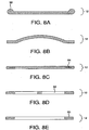
- the removable support member 12 may comprise one or more variations including but not limited to an edge reinforcement 30; a non-planar configuration ( FIGURE 8B ); internal reinforcement such as a reinforcing ring 84 ( FIGURE 8C ); a non-continuous reinforcement configuration 32 ( FIGURE 8D ), an open centered configuration such as a peripheral ring 85 depicted in FIGURE 8E .
- FIGURE 11A illustrates a top view of an alternative removable support member 12 which is able to be quickly removed by the application of a force parallel to the support member.
- FIGURE 11B illustrates a cross-sectional view of a removable support member 12 with an upward force required for removal from the cuff 10. Other variations are contemplated but not depicted.
- FIGURE 9A shows a cuff 10 formed by gathering a planar sheet of tissue repair material 3 so that the individual fold 11 may be pleated and affixed to accommodate the shape of a desired removable support 12.
- FIGURE 9B shows the pleated fold 11 affixed to allow retention of the removable support member 12.
- FIGURE 10 illustrates a top plan view of various shapes and configurations of the present invention wherein the tissue repair material 3 sheet is covered by the continuous overlapping cuff 10. The continuous cuff 10 need only be sized to secure the removable support during placement of the device.
- the percentage of the tissue repair material 3 sheet which remains uncovered and free of the overlapping continuous cuff 10 formed by the outer perimeter 9 overlapping onto a side of the tissue repair material 3 may range between 5 percent to 95 percent depending upon the configuration of the cuff 10 and the device, but a typical device greater than half of the sheet is exposed. In one embodiment as shown in FIGURE 10 , more than sixty percent of the tissue repair material 3 sheet remains exposed and separate from the continuous cuff 10. In this example about 40 percent of the tissue repair material 3 sheet is covered by the continuous overlapping cuff 10.
- the implantable medical device 1 may be comprised of a tissue repair material 3 sheet having two sides and an outer perimeter 9 with at least one side adapted for ingrowth of cells.
- the cuff 10 may be formed from the outer perimeter 9 to overlap onto a side of the tissue repair material 3 allowing a desired amount of a side adapted for ingrowth of cells of the material sheet exposed. It is desirable in certain configurations such as shown in FIGURES 6 , 7 , 10 , and 12 to have greater than half of the tissue repair material 3 sheet exposed and outside of the continuous overlapping cuff 10.
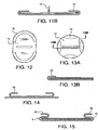
- FIGURE 12 illustrates a top plan view of a non-continuous cuff 10 comprising two segments of a device that is outwith the scope of the present invention.
- FIGURE 13A illustrates a top plan view of a non-continuous cuff 10 comprising four segments of a device that is outwith the scope of the present invention.
- FIGURE 13B illustrates a cross-sectional view (of a device that is outwith the scope of the present invention) of a non-continuous cuff 10 showing how the segment retains the removable support member.
- the support member may comprise a solid planar removable support member or may comprise a support member which is of relatively open weave such that points of securement occur at some or all of the non-continuous cuff 10 segments.
- the device may be formed of multiple planar layers so that the cuff 10 may be formed of one or more of the layers, as shown by the cross-sectional view of a two-layer mesh material with the bottom layer extending beyond the cuff 10.
- This type of an application may be advantageous for securing the patch over or around both symmetrical and nonsymmetrical incisions.
- the implantable medical device 1 may comprise a tissue repair material 3 having two sides and an outer perimeter, formed so that a first cuff 10 from the outer perimeter 9 of the tissue repair material 3 overlaps onto a side of the tissue repair material 3 and is folded back upon itself forming another cuff (hereinafter referred to as a second cuff 50 for clarity of the invention) from the inner perimeter of the first cuff.
- the second cuff 50 overlaps onto a side of the first cuff.
- tissue adjacent to the site of incision may be enclosed between the first cuff and the overlapping flap of the second cuff. This configuration allows for securement through second cuff, the enclosed tissue and the first cuff.
- the removable support member 12 may then be dislodged leaving the patch firmly secured.
- the implantable medical device 1 may be easily placed by attaching one or more suture threads to the perimeter of the device; inserting the surgically implantable device through an incision in the patient; opening and positioning the surgically implantable device such that the device extends beyond the perimeter of the defect; affixing the device to surrounding tissue via the one or more suture threads; and securing the device about the outer perimeter 9 of the device so as to attach the surgically implantable device to the patient.
- the device may be secured about the outer perimeter 9 using surgical tacks, surgical staples, and surgical sutures.
- the surgically implantable device may be inserted during an open procedure or laproscopically.
- the implantable medical device 1 may be placed by various anchoring mechanisms including: attaching one or more suture threads to the perimeter of the device; inserting the surgically implantable device through an incision in the patient; opening and positioning the surgically implantable device such that the device extends beyond the perimeter of the defect; affixing the device to surrounding tissue via the one or more suture threads; securing the device about the outer perimeter 9 of the device so as to attach the surgically implantable device to the patient; and removing the support member
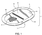
- This example describes the construction of a preferred embodiment of the present invention. Following the formation of a support member and the formation of a cuffed implantable sheet material, the support member is fit together with the implantable sheet material such that the formed cuff retains the support member as shown in FIGURE 1 .
- the implantable sheet has a peripheral cuff formed from a continuous implantable sheet such that is folded back onto itself along the entire perimeter between 10.0 mm and 12.0 mm.
- the implantable sheet was an expanded polytetrafluoroethylene (ePTFE) trade named GORE-TEX® DUALMESH® Biomaterial supplied from the Medical Products Division of W. L. Gore & Associates, Inc. (Flagstaff, AZ).
- the GORE-TEX® DUALMESH® Biomaterial product has a different texture on each side of the sheet. One side is designed to prevent or limit tissue adhesions or other tissue attachments thereto. The other side is roughened to encourage tissue attachment or ingrowth of cells or cellular process therewithin.
- the GORE-TEX® DUALMESH® Biomaterial was oriented so that the roughened "tissue ingrowth" side is oriented toward the support member.
- the cuff was formed by taking the flat implantable sheet as shown in FIGURE 5A and placing a 10 cm x 15 cm oval folding template on the smooth tissue adhesion barrier side of the implantable sheet and folding the remaining material of the implantable sheet over the edge of the folding plate.
- the folding plate was formed from a 0.030" (0.762mm) polycarbonate sheet, part number 85585K17, available from McMaster Carr®, Atlanta, GA.
- the slack of the folded cuff was taken up into sixteen evenly distributed pleats on each end of the oval, as shown in FIGURE 9A and temporarily secured by compressing the pleat using smooth faced pliers, part number 5157A42, available from McMaster Carr®, Atlanta, GA.
- the folding plate was removed and as shown in FIGURE 9B , these pleats were then sewn at each of their bases using a Series LK- 1850 bar tacking sewing machine, available from Juki Corporation, Tokyo, Japan, using CV-5 suture material, supplied from the Medical Products Division of W. L. Gore & Associates, Inc. (Flagstaff, AZ).
- the formed cuffed implantable sheet was then inverted so the cuff was opposite of the smooth tissue adhesion barrier side.
- the support member is formed from a continuous sheet of 0.015" (0.381mm) stiff, flexible, resilient material so that when it is bent it wants to return to a flat shape without plastic deformation.
- the support member has a slit cut into the middle of the sheet lengthwise and 1 ⁇ 4" (6.35mm) semi-circular relief cut out in each quadrant, as shown in FIGURE 7 .
- the slit is to allow access for positioning during use and the semi-circular relief cut outs are to allow for suture placement without interference with the support member.
- the support member is cut from a flat sheet of polycarbonate film, part number 85585K14, available from McMaster Carr®, Atlanta, GA, using a CO2 laser, model SL4200 laser, available from Preco, Inc., Lenexa, KS.
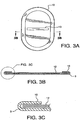
- the support member is then fit together with the cuffed implantable sheet so that the support member is constrained by the cuff, as shown in FIGURE 3B .
- the combined components were placed into a heated platen press under 30 psi (207kPA), at 100°C under for 30 seconds to flatten and conform the cuffed implantable sheet to the support member.
Description
- Surgically implanted patches are used to treat wall defects, such as hernia, umbilical repairs and other such defects. The patches are typically implanted and remain in a patient. Several patents and/or published patent applications were identified for hernia patches comprising two layers of biocompatible mesh with one or more pouches, pockets or slits for insertion of either a surgeon's finger or a trocar or other fastening and/or positioning tool to aid in implanting the hernia patch.
-
U.S. Patent Nos. 5,634,931 ,5,769,864 , and5,916,225 by Kugel which disclose hernia patches comprising a first layer of inert mesh material selectively sized and shaped to extend across and beyond a hernia, a second layer of inert synthetic mesh material which overlies the first layer, wherein the first and second layers are joined together to define a periphery of a pouch between the two layers, and a resilient monofilament loop located within the pouch to urge the patch to conform to a planar configuration. An access slit is formed in one of the layers for insertion of the surgeon's finger into the pouch to facilitate insertion.U.S. Patents 6,176,863 and6,280,453 by Kugel et al. disclose similar hernia mesh patches with a single slit for insertion of the surgeon's finger. -
U.S. Patent No. 6,174,320 by Kugel et al. discloses a hernia patch with an additional slit through both layers of the mesh material and terminating in an enlarged opening for placement around a patient's chord structure. This hernia patch is used in repair of inguinal hernias. -
U.S. Publication No. 2004/0215219 by Eldridge et al. discloses an implantable prosthesis for hernia repair comprising two layers of material that permit the formation of adhesion with tissue or muscle, at least one pocket, more preferably two pockets formed between the first and second layers for insertion of a surgeon's fingers and a layer of barrier material resistant to formation of adhesions with tissue or muscle attached to the second layer at discrete locations. - In addition,
U.S. Patent No. 5,922,026 by Chin discloses a prosthetic strip or patch which includes pockets at each end into which a fastener tool can be inserted and used to position and secure the patch to tissues and ligaments in the body. -
WO 02/22047 - There is a strong need in the art for a flexible tissue repair patch which allows for accuracy and ease in delivery and placement by a surgeon. It is also desired that the patch provides improved protection of the surrounding tissues during procedures such as hernia repairs.
- The present invention fills the need in that it is different from the slit and finger fitting pockets described in the above hernia patches. Additionally, the present invention allows for fixation of the patch at the outer most perimeter of the implanted patch.
- An implantable medical device is provided comprising a tissue repair material having two sides and an outer perimeter with at least one side adapted for ingrowth of cells, and a cuff formed from the entire outer perimeter to overlap onto a side of the tissue repair material, creating an opening between the cuff and the tissue repair material wherein the cuff forms a fixation area at the outer edge of the device for use in joining the device to tissues of a patient. A removable support member may be removably positioned under the cuff for ease of use manipulation during implant procedures.
-
-
FIGURE 1 illustrates a perspective view of the present invention. -
FIGURE 2 illustrates an exploded view of the present invention including a removable support member. -
FIGURE 3A illustrates a top plan view of the present invention. -
FIGURE 3B illustrates a cross-sectional view of the present invention showing how the cuff retains the removable support member. -
FIGURE 3C illustrates a detailed section view of the mesh material with the formed cuff retaining the removable support member. -
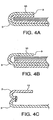
FIGURE 4A illustrates a mesh material constructed from a composite material, having more than one continuous layer. -
FIGURE 4B illustrates a mesh material constructed from a non-continuous composite material, having more than one layer. -
FIGURE 4C illustrates a mesh material constructed from more than one material. -
FIGURE 5A illustrates a bottom plan view of the mesh prior to cuff forming showing the fold line and the section of bottom surface area that has been roughened. -
FIGURE 5B illustrates a cross-sectional view of the mesh prior to cuff forming showing the top and bottom surface areas that have been roughened. -
FIGURE 5C illustrates a cross-sectional view of the device after cuff formation showing the orientation of the surfaces that have been roughened. -
FIGURE 5D illustrates a cross-sectional view of the device after cuff formation showing the orientation of the surfaces that have been roughened. -
FIGURE 6A illustrates a top plan view of the present invention. -
FIGURE 6B illustrates a top plan view of the present invention showing an alternative cuff form. -
FIGURE 6C illustrates a cross-sectional view of the mesh showing a continuous cuff. -
FIGURE 6D illustrates a cross-sectional view of the mesh showing a non-continuous cuff. -
FIGURE 7 illustrates a top plan view of various removable support member designs showing that the support member can have a continuous boundary, a slit boundary, a boundary with relief cuts as well as different access hole configurations. -
FIGURE 8A illustrates a cross-sectional view of the removable support member showing an edge reinforcement. -
FIGURE 8B illustrates a cross-sectional view of the removable support member showing a non-planar configuration. -
FIGURE 8C illustrates a cross-sectional view of the removable support member showing internal reinforcement. -
FIGURE 8D illustrates a cross-sectional view of the removable support member showing a non-continuous configuration. -
FIGURE 8E illustrates a cross-sectional view of the removable support member showing a peripheral ring only configuration. -
FIGURE 9A illustrates a top plan view of a mesh during manufacture showing a pleated cuff configuration. -
FIGURE 9B illustrates a cross-sectional view of the mesh during manufacture showing a pleat construction. -
FIGURE 10 illustrates a top plan view of various shapes and configurations of the present invention. -
FIGURE 11A illustrates a top plan view of an alternative removable support member. -
FIGURE 11B illustrates a cross-sectional view of an alternative removable support member and the direction of removal. -
FIGURE 12 illustrates a top plan view of a non-continuous cuff showing two segments of a device that is outwith the scope of the present invention. -
FIGURE 13A illustrates a top plan view of a non-continuous cuff showing four segments of a device that is outwith the scope of the present invention. -
FIGURE 13B illustrates a cross-sectional view of a non-continuous cuff showing how the segment retains the removable support member of a device that is outwith the scope of the present invention. -
FIGURE 14 illustrates a cross-sectional view of a two-layer mesh material with the bottom layer extending beyond the cuff. -
FIGURE 15 illustrates a cross-sectional view of a device with a first cuff and a second cuff formed by folding the first cuff over onto the first cuff. - The present invention is an implantable device designed to repair damaged tissue such as soft tissue defects, wall defects, hernia, umbilical repairs and other such defects. The device is formed of a planar tissue repair material having two sides and an outer perimeter, and a cuff formed from the outer perimeter of the tissue repair material to overlap onto a side of the tissue repair material. The present invention may further include a removable support member over which the tissue repair material is overlapped to cover at least a portion of the removable support member.
- As shown in
FIGURE 1 , an implantablemedical device 1 is formed from a planar sheet oftissue repair material 3. Thetissue repair material 3 has two sides shown astop side 5 andbottom side 7 and anouter perimeter 9. Acuff 10 is shown formed from thetissue repair material 3 to overlap onto a side of thetissue repair material 3. Thecuff 10 allows afixation area 18 to be formed on thecuff 10, and in particular at theouter edge 20 of the implantablemedical device 1. Aremoval support member 12 fits under the cuff for implantation ease. - The
tissue repair material 3 may be any material suitable for medical use, for instance, polymeric materials including polytetrafluoroethylenes and expanded polytetrafluoroethylenes. While thetissue repair material 3 is shown as having a smooth outer perimeter, the invention is not limited to this configuration. It is anticipated that theouter perimeter 9 of thetissue repair material 3 could be smooth, irregular, patterned, notched or other shaped variations. It is further contemplated thattissue repair material 3 may comprise variations consistent with the embodied invention, depending on the application for which it is intended. For instance, thetissue repair material 3 may be comprised of a single material composition, as shown inFIGURES 3A through 3C ; or may comprise two or more materials, as shown inFIGURE 4A as a composite material having more than one continuous layer.FIGURE 4B further illustrates thattissue repair material 3 can be constructed from a non-continuous composite material, having more than one layer. Thetissue repair material 3 is preferred to be in the form of a single piece of material which achieves the overlap making thecuff 10, by folding the edges of theouter perimeter 9 of thetissue repair material 3 onto a side. However, it is readily apparent that more than one piece oftissue repair material 3 may be used with the device, as shown inFIGURE 4C. FIGURE 4C shows the use of a single piece of material which forms the bottom side joined to at least one piece of material to form thecuff 10. The pieces may be joined at their perimeter, by sewing, ultrasonic welding, bonding, or other suitable methods to form a device with two sides and an outer perimeter. - The
tissue repair material 3 may be in the form of a sheet, mesh, web, wovens, nonwovens, knits, or any other suitable material. In one embodiment the implantable device of the present invention is comprised of atissue repair material 3 that is an infection resistant mesh material. In this embodiment thetissue repair material 3 comprises one or more matrix-forming polymers, such as biomedical polyurethanes, biomedical silicones and biodegradable polymers and antimicrobial agents, and combinations of matrix-forming polymers with therapeutic agents such as silver salts and/or chlorhexidine or its salts. - The matrix may be coated with an antimicrobial agent in a solvent solution, causing the coating material to enter into the interstices and dry, resulting in an infection resistant matrix.
- The
tissue repair material 3 may further have one or both sides adapted to allow an ingrowth of cells. In another aspect, thetissue repair material 3 may comprise at least one bioabsorbable material. The biosorbable material may be present throughout thetissue repair material 3 or may exist on designated areas only. - The
cuff 10 formed on the device is continuous with and integral to thetissue repair material 3. Thecuff 10 andtissue repair material 3 may be formed of substantially the same materials, or substantially different materials depending upon the desired application of the resulting device. Thecuff 10 may be formed as one continuous channel around theouter edge 20 of the device or into individual segmented compartments 16. - In one embodiment, the
cuff 10 may be adapted to prevent cell ingrowth, or alternatively promote cell ingrowth in designated areas. - As shown in
FIGURE 2 , aremovable support member 12 is of a suitable configuration to be inserted into the implantablemedical device 1, so that it is seated between the top side of thetissue repair material 3 and thecuff 10. It is desirable for the removable support member to extend to the outer edge of the device to ensure a sufficient deployment of the device during implantation. The removable support member allows the patch to be easily positioned during implantation. Further, the removable support member allows the patch to remain open during manipulation, and promotes easy guided tack fixation and improved suture placement. The removable support member is oriented between the top side and thecuff 10. Thecuff 10 covers secured tacks, protecting or preventing exposure to the surrounding tissue. In one aspect of the invention, theremovable support member 12 provides access to theouter edge 20 of thedevice 1 for suturing or joining to tissues of a patient. The removable support member provides resistant shield to prevent puncture of the underlying tissues during tacking or stapling of the device in place. -
FIGURES 3A, 3B and 3C illustrate retention of theremovable support member 12 by thecuff 10. Agrip 13 may be present on the removable support member in the form of a cutout, handle or other suitable aid for manipulation of the removable support during implantation procedures. As shown inFIGURE 7 , variousremovable support member 12 designs are contemplated by the present invention. Theremovable support member 12 can have a continuous boundary, a slit boundary, a boundary with relief cuts as well asmultiple grip 13 configurations. -
FIGURE 5A illustrates a bottom planar view of thebottom side 7 of thetissue repair material 3 prior to cuff formation showing afold line 22 which creates the overlapped cuff. It may be desirable to incorporate at least one section of bottom surface area that has been roughened, leaving other sections of thetissue repair material 3 surfaces smooth to promote variable cellular ingrowth.FIGURE 5B illustrates a cross-sectional view of the mesh prior to cuff formation. In this embodiment, both thetop side 5 andbottom side 7 surface areas have been roughened. Only the end portions of thetissue repair material 3 on the bottom side have been roughened in this view, so that when formed into acuff 10 atfold line 22 as shown inFIGURE 5C , the roughened areas all are present on the same side of the device. It should be noted that the device may be oriented in different positions depending upon the desired use, and insertion method. One of the advantages of a smooth surface which is fully continuous, as shown here across the bottom side of the device, is that a continuous barrier property may be achieved across the entire bottom side of the device. The barrier property is useful to prevent adhesions. Particularly useful barriers include ePTFE and PTFE. - While the device of the present invention is particularly suited for open repairs,
FIGURE 5D shows one configuration which would be particularly suited for laproscopic insertion, as well. -
FIGURES 6A and 6B illustrate a top plan view of the present invention withalternative cuff 10 forms.FiGURE 6A has acuff 10 formed as a continuous channel with the opening to thecuff 10 located about theouter perimeter 9 of thetissue repair material 3.FiGURE 6B shows asegmented cuff 10 formed as individual segmented compartments 16. The openings to the individual segmented compartments are about theouter perimeter 9 of thetissue repair material 3.FIGURE 6C illustrates a cross-sectional view of the mesh showing acontinuous cuff 10.FIGURE 6D illustrates a cross-sectional view of the mesh showing anon-continuous cuff 10, with individual segmented compartments 16. In bothFIGURES 6C and 6D , theremovable support member 12 is configured to fit into thecuff 10 for easy use of the device. - One of the many advantages of the present invention is that the
removable support 12 may be easily and delicately grasped and removed once the implant is in place. As shown inFIGURES 6 ,7 ,10 and12 , a surgeon may grasp theremovable support member 12 viaopenings 80 or holes using either his or her fingers or a surgical tool such as forceps. Insertion of the fingers or a tool into a fitted pocket does not necessitate delicate removal of the finger or tool from the fitted pocket once the implant is in place, as other devices require. Further, other devices which require insertion of the surgeon's fingers or a tool into a fitted pocket make delicate removal of the finger or tool from the fitted pocket difficult once the implant is in place. -
FIGURES 8A through 8E show cross-sectional views of contemplated variations of the removable support member. Theremovable support member 12 may comprise one or more variations including but not limited to anedge reinforcement 30; a non-planar configuration (FIGURE 8B ); internal reinforcement such as a reinforcing ring 84 (FIGURE 8C ); a non-continuous reinforcement configuration 32 (FIGURE 8D ), an open centered configuration such as aperipheral ring 85 depicted inFIGURE 8E .FIGURE 11A illustrates a top view of an alternativeremovable support member 12 which is able to be quickly removed by the application of a force parallel to the support member.FIGURE 11B illustrates a cross-sectional view of aremovable support member 12 with an upward force required for removal from thecuff 10. Other variations are contemplated but not depicted. -
FIGURE 9A shows acuff 10 formed by gathering a planar sheet oftissue repair material 3 so that theindividual fold 11 may be pleated and affixed to accommodate the shape of a desiredremovable support 12.FIGURE 9B shows thepleated fold 11 affixed to allow retention of theremovable support member 12.FIGURE 10 illustrates a top plan view of various shapes and configurations of the present invention wherein thetissue repair material 3 sheet is covered by the continuous overlappingcuff 10. Thecontinuous cuff 10 need only be sized to secure the removable support during placement of the device. The percentage of thetissue repair material 3 sheet which remains uncovered and free of the overlappingcontinuous cuff 10 formed by theouter perimeter 9 overlapping onto a side of thetissue repair material 3 may range between 5 percent to 95 percent depending upon the configuration of thecuff 10 and the device, but a typical device greater than half of the sheet is exposed. In one embodiment as shown inFIGURE 10 , more than sixty percent of thetissue repair material 3 sheet remains exposed and separate from thecontinuous cuff 10. In this example about 40 percent of thetissue repair material 3 sheet is covered by the continuous overlappingcuff 10. The implantablemedical device 1 may be comprised of atissue repair material 3 sheet having two sides and anouter perimeter 9 with at least one side adapted for ingrowth of cells. Thecuff 10 may be formed from theouter perimeter 9 to overlap onto a side of thetissue repair material 3 allowing a desired amount of a side adapted for ingrowth of cells of the material sheet exposed. It is desirable in certain configurations such as shown inFIGURES 6 ,7 ,10 , and12 to have greater than half of thetissue repair material 3 sheet exposed and outside of the continuous overlappingcuff 10. -
FIGURE 12 illustrates a top plan view of anon-continuous cuff 10 comprising two segments of a device that is outwith the scope of the present invention.FIGURE 13A illustrates a top plan view of anon-continuous cuff 10 comprising four segments of a device that is outwith the scope of the present invention.FIGURE 13B illustrates a cross-sectional view (of a device that is outwith the scope of the present invention) of anon-continuous cuff 10 showing how the segment retains the removable support member. As is clear byFIGURES 12 and 13A , the support member may comprise a solid planar removable support member or may comprise a support member which is of relatively open weave such that points of securement occur at some or all of thenon-continuous cuff 10 segments. - As shown in
FIGURE 14 , the device may be formed of multiple planar layers so that thecuff 10 may be formed of one or more of the layers, as shown by the cross-sectional view of a two-layer mesh material with the bottom layer extending beyond thecuff 10. This type of an application may be advantageous for securing the patch over or around both symmetrical and nonsymmetrical incisions. - In another embodiment, as shown in
FIGURE 15 , the implantablemedical device 1 may comprise atissue repair material 3 having two sides and an outer perimeter, formed so that afirst cuff 10 from theouter perimeter 9 of thetissue repair material 3 overlaps onto a side of thetissue repair material 3 and is folded back upon itself forming another cuff (hereinafter referred to as asecond cuff 50 for clarity of the invention) from the inner perimeter of the first cuff. Thesecond cuff 50 overlaps onto a side of the first cuff. In one aspect of this embodiment, tissue adjacent to the site of incision may be enclosed between the first cuff and the overlapping flap of the second cuff. This configuration allows for securement through second cuff, the enclosed tissue and the first cuff. Theremovable support member 12 may then be dislodged leaving the patch firmly secured. The implantablemedical device 1 may be easily placed by attaching one or more suture threads to the perimeter of the device; inserting the surgically implantable device through an incision in the patient; opening and positioning the surgically implantable device such that the device extends beyond the perimeter of the defect; affixing the device to surrounding tissue via the one or more suture threads; and securing the device about theouter perimeter 9 of the device so as to attach the surgically implantable device to the patient. The device may be secured about theouter perimeter 9 using surgical tacks, surgical staples, and surgical sutures. The surgically implantable device may be inserted during an open procedure or laproscopically. - The implantable
medical device 1 may be placed by various anchoring mechanisms including: attaching one or more suture threads to the perimeter of the device; inserting the surgically implantable device through an incision in the patient; opening and positioning the surgically implantable device such that the device extends beyond the perimeter of the defect; affixing the device to surrounding tissue via the one or more suture threads; securing the device about theouter perimeter 9 of the device so as to attach the surgically implantable device to the patient; and removing the support member - The following examples are provided to further illustrate the present invention. These examples are provided to illustrate certain aspects of the invention and are not intended to limit the scope of the invention.
- This example describes the construction of a preferred embodiment of the present invention. Following the formation of a support member and the formation of a cuffed implantable sheet material, the support member is fit together with the implantable sheet material such that the formed cuff retains the support member as shown in
FIGURE 1 . - The implantable sheet has a peripheral cuff formed from a continuous implantable sheet such that is folded back onto itself along the entire perimeter between 10.0 mm and 12.0 mm. The implantable sheet was an expanded polytetrafluoroethylene (ePTFE) trade named GORE-TEX® DUALMESH® Biomaterial supplied from the Medical Products Division of W. L. Gore & Associates, Inc. (Flagstaff, AZ). The GORE-TEX® DUALMESH® Biomaterial product has a different texture on each side of the sheet. One side is designed to prevent or limit tissue adhesions or other tissue attachments thereto. The other side is roughened to encourage tissue attachment or ingrowth of cells or cellular process therewithin. The GORE-TEX® DUALMESH® Biomaterial was oriented so that the roughened "tissue ingrowth" side is oriented toward the support member. The cuff was formed by taking the flat implantable sheet as shown in
FIGURE 5A and placing a 10 cm x 15 cm oval folding template on the smooth tissue adhesion barrier side of the implantable sheet and folding the remaining material of the implantable sheet over the edge of the folding plate. The folding plate was formed from a 0.030" (0.762mm) polycarbonate sheet, part number 85585K17, available from McMaster Carr®, Atlanta, GA. The slack of the folded cuff was taken up into sixteen evenly distributed pleats on each end of the oval, as shown inFIGURE 9A and temporarily secured by compressing the pleat using smooth faced pliers, part number 5157A42, available from McMaster Carr®, Atlanta, GA. The folding plate was removed and as shown inFIGURE 9B , these pleats were then sewn at each of their bases using a Series LK- 1850 bar tacking sewing machine, available from Juki Corporation, Tokyo, Japan, using CV-5 suture material, supplied from the Medical Products Division of W. L. Gore & Associates, Inc. (Flagstaff, AZ). The formed cuffed implantable sheet was then inverted so the cuff was opposite of the smooth tissue adhesion barrier side. - The support member is formed from a continuous sheet of 0.015" (0.381mm) stiff, flexible, resilient material so that when it is bent it wants to return to a flat shape without plastic deformation. The support member has a slit cut into the middle of the sheet lengthwise and ¼" (6.35mm) semi-circular relief cut out in each quadrant, as shown in
FIGURE 7 . The slit is to allow access for positioning during use and the semi-circular relief cut outs are to allow for suture placement without interference with the support member. - The support member is cut from a flat sheet of polycarbonate film, part number 85585K14, available from McMaster Carr®, Atlanta, GA, using a CO2 laser, model SL4200 laser, available from Preco, Inc., Lenexa, KS.
- The support member is then fit together with the cuffed implantable sheet so that the support member is constrained by the cuff, as shown in
FIGURE 3B . The combined components were placed into a heated platen press under 30 psi (207kPA), at 100°C under for 30 seconds to flatten and conform the cuffed implantable sheet to the support member. - While particular embodiments of the present invention have been illustrated and described herein, the present invention should not be limited to such illustrations and descriptions. It should be apparent that changes and modifications may be incorporated and embodied as part of the present invention within the scope of the following claims.
Claims (23)
- An implantable medical device (1) comprising:a. a tissue repair material (3) having two sides and an outer perimeter with at least one side adapted for ingrowth of cells; andb. a cuff (10) formed from the entire outer perimeter (20) to overlap onto a side of the tissue repair material (3), creating an opening between the cuff and the tissue repair material wherein the cuff (10) forms a fixation area (18) at the outer edge of the device for use in joining the device (1) to tissues of a patient.
- The implantable medical device of claim 1 further comprising a removable support member (12) wherein the tissue repair material (3) is folded over at least a portion of said removable support member (12).
- The implantable medical device of claim 2 wherein the tissue repair material (3) is folded over the support member (12) to form a continuous border (10) which extends around the perimeter (20) of the support member (12).
- The implantable medical device of claim 3 wherein the continuous border (10) comprises individual pockets (16).
- The implantable medical device of claim 2 wherein the support member (12) is resistant to puncture from fixation device.
- The implantable medical device of claim 1 wherein the tissue repair material (3) is conformable.
- The implantable medical device of claim 1 wherein the cuff (10) is continuous with and integral to the tissue repair material (3).
- The implantable medical device of claim 1 wherein the cuff (10) and tissue repair material (3) are formed of substantially the same materials.
- The implantable medical device of claim 1 wherein the cuff (10) and tissue repair material (3) are formed of substantially different materials.
- The implantable medical device of claim 1 wherein tissue repair material (3) is a single material composition.
- The implantable medical device of claim 1 wherein tissue repair material (3) comprises expanded polytetrafluoroethylene.
- The implantable medical device of claim 1 wherein tissue repair material (3) is a composite of two or more materials.
- The implantable medical device of claim 11 wherein tissue repair material (3) is expanded polytetrafluoroethylene.
- The implantable medical device of claim 1 wherein tissue repair material (3) comprises at least one bioabsorbable material.
- The implantable medical device of claim 1 wherein the cuff (10) has individual segmented compartments (16).
- The implantable medical device of claim 1 wherein the tissue repair material (3) has one or more sides adapted for ingrowth.
- The implantable medical device of claim 1, wherein the cuff (10) formed from the outer perimeter (9) of the tissue repair material (3) to overlap onto a side of the tissue repair material (3) provides a first cuff that is foldable back on itself to form a second cuff (50) from the inner perimeter of the first cuff to overlap onto a side of the first cuff (10).
- The implantable medical device of claim 2 wherein the tissue repair material (3) is affixed via a pressure sensitive adhesive to at least a portion of the removable support member.
- The implantable medical device of claim 2, whereina. the tissue repair material (3) has a top and bottom side; andb. the removable support member (12) has a top side, a bottom side, and an outer perimeter, and oriented so that the tissue repair material is in contact with the bottom side of the support member and also in contact with at least a portion of the top side of the support member to form a continuous cuff which extends around and encloses the perimeter of the support member.
- The implantable medical device of claim 2, wherein the cuff (10) is adapted for cell ingrowth.
- The implantable medical device of claim 1, wherein the cuff (10) is adapted to prevent cell ingrowth.
- The implantable medical device of claim 1, wherein the cuff (10) is adapted to promote cell ingrowth in designated areas.
- The implantable medical device of claim 1, wherein the cuff (10) is formed from the outer perimeter to overlap onto a side of the tissue repair material (3) so that less than 40 percent of the tissue repair material sheet is covered by a continuous overlapping cuff (10).
Applications Claiming Priority (2)
| Application Number | Priority Date | Filing Date | Title |
|---|---|---|---|
| US11/474,673 US20070299538A1 (en) | 2006-06-26 | 2006-06-26 | Ease of use tissue repair patch |
| PCT/US2007/014776 WO2008002549A2 (en) | 2006-06-26 | 2007-06-22 | Ease of use tissue repair patch |
Publications (3)
| Publication Number | Publication Date |
|---|---|
| EP2032073A2 EP2032073A2 (en) | 2009-03-11 |
| EP2032073B1 EP2032073B1 (en) | 2012-08-22 |
| EP2032073B2 true EP2032073B2 (en) | 2017-06-07 |
Family
ID=38846254
Family Applications (1)
| Application Number | Title | Priority Date | Filing Date |
|---|---|---|---|
| EP07809885.2A Active EP2032073B2 (en) | 2006-06-26 | 2007-06-22 | Ease of use tissue repair patch |
Country Status (7)
| Country | Link |
|---|---|
| US (1) | US20070299538A1 (en) |
| EP (1) | EP2032073B2 (en) |
| JP (1) | JP2009541011A (en) |
| AU (1) | AU2007265524B2 (en) |
| CA (1) | CA2656272C (en) |
| ES (1) | ES2391990T3 (en) |
| WO (1) | WO2008002549A2 (en) |
Families Citing this family (82)
| Publication number | Priority date | Publication date | Assignee | Title |
|---|---|---|---|---|
| US8795383B2 (en) * | 2004-07-19 | 2014-08-05 | Alfredo Alvarado | Laparoscopic inguinal hernia prosthesis |
| US9801982B2 (en) | 2004-09-28 | 2017-10-31 | Atrium Medical Corporation | Implantable barrier device |
| WO2006036967A1 (en) | 2004-09-28 | 2006-04-06 | Atrium Medical Corporation | Solubilizing a drug for use in a coating |
| US9000040B2 (en) | 2004-09-28 | 2015-04-07 | Atrium Medical Corporation | Cross-linked fatty acid-based biomaterials |
| US8312836B2 (en) | 2004-09-28 | 2012-11-20 | Atrium Medical Corporation | Method and apparatus for application of a fresh coating on a medical device |
| US8367099B2 (en) | 2004-09-28 | 2013-02-05 | Atrium Medical Corporation | Perforated fatty acid films |
| US9012506B2 (en) | 2004-09-28 | 2015-04-21 | Atrium Medical Corporation | Cross-linked fatty acid-based biomaterials |
| US8962023B2 (en) | 2004-09-28 | 2015-02-24 | Atrium Medical Corporation | UV cured gel and method of making |
| US9278161B2 (en) * | 2005-09-28 | 2016-03-08 | Atrium Medical Corporation | Tissue-separating fatty acid adhesion barrier |
| US9427423B2 (en) | 2009-03-10 | 2016-08-30 | Atrium Medical Corporation | Fatty-acid based particles |
| CA2626030A1 (en) | 2005-10-15 | 2007-04-26 | Atrium Medical Corporation | Hydrophobic cross-linked gels for bioabsorbable drug carrier coatings |
| US7544213B2 (en) * | 2006-09-12 | 2009-06-09 | Adams Jason P | Inflatable hernia patch |
| US9492596B2 (en) | 2006-11-06 | 2016-11-15 | Atrium Medical Corporation | Barrier layer with underlying medical device and one or more reinforcing support structures |
| WO2008057344A2 (en) * | 2006-11-06 | 2008-05-15 | Atrium Medical Corporation | Coated surgical mesh |
| US9308068B2 (en) * | 2007-12-03 | 2016-04-12 | Sofradim Production | Implant for parastomal hernia |
| US9242026B2 (en) | 2008-06-27 | 2016-01-26 | Sofradim Production | Biosynthetic implant for soft tissue repair |
| WO2010039249A1 (en) * | 2008-10-03 | 2010-04-08 | C.R. Bard, Inc. | Implantable prosthesis |
| US20100152530A1 (en) * | 2008-12-15 | 2010-06-17 | Mark Timmer | Biocompatible Fiber Based Device for Guided Tissue Regeneration |
| WO2010093333A1 (en) * | 2009-02-11 | 2010-08-19 | Nanyang Technological University | Multi-layered surgical prosthesis |
| WO2010132545A1 (en) * | 2009-05-14 | 2010-11-18 | Wilson-Cook Medical Inc. | Systems and methods for securing a graft member to tissue using one or more tacking devices |
| US20110038910A1 (en) | 2009-08-11 | 2011-02-17 | Atrium Medical Corporation | Anti-infective antimicrobial-containing biomaterials |
| FR2949688B1 (en) | 2009-09-04 | 2012-08-24 | Sofradim Production | FABRIC WITH PICOTS COATED WITH A BIORESORBABLE MICROPOROUS LAYER |
| EP2544623B1 (en) | 2010-03-09 | 2018-01-10 | Solinas Medical Inc. | Self-closing devices |
| WO2012009707A2 (en) | 2010-07-16 | 2012-01-19 | Atrium Medical Corporation | Composition and methods for altering the rate of hydrolysis of cured oil-based materials |
| FR2972626B1 (en) | 2011-03-16 | 2014-04-11 | Sofradim Production | PROSTHETIC COMPRISING A THREE-DIMENSIONAL KNIT AND ADJUSTED |
| FR2977790B1 (en) | 2011-07-13 | 2013-07-19 | Sofradim Production | PROSTHETIC FOR UMBILIC HERNIA |
| FR2977789B1 (en) | 2011-07-13 | 2013-07-19 | Sofradim Production | PROSTHETIC FOR UMBILIC HERNIA |
| US8579924B2 (en) * | 2011-07-26 | 2013-11-12 | Covidien Lp | Implantable devices including a mesh and a pivotable film |
| CA2849052C (en) | 2011-09-30 | 2019-11-05 | Sofradim Production | Reversible stiffening of light weight mesh |
| FR2985171B1 (en) | 2011-12-29 | 2014-06-06 | Sofradim Production | PROSTHETIC FOR HERNIA WITH MEDIUM MARKING |
| FR2985271B1 (en) | 2011-12-29 | 2014-01-24 | Sofradim Production | KNITTED PICOTS |
| FR2985170B1 (en) | 2011-12-29 | 2014-01-24 | Sofradim Production | PROSTHESIS FOR INGUINAL HERNIA |
| WO2013142353A1 (en) | 2012-03-22 | 2013-09-26 | C.R. Bard, Inc. | Implantable prosthesis for soft tissue repair |
| US8945235B2 (en) | 2012-03-27 | 2015-02-03 | Atrium Medical Corporation | Removable deployment device, system, and method for implantable prostheses |
| US9820837B2 (en) | 2012-04-10 | 2017-11-21 | Ethicon, Inc. | Single plane tissue repair patch |
| US9820838B2 (en) * | 2012-04-10 | 2017-11-21 | Ethicon, Inc. | Single plane tissue repair patch |
| US9820839B2 (en) * | 2012-04-10 | 2017-11-21 | Ethicon, Inc. | Single plane tissue repair patch having a locating structure |
| US9867880B2 (en) | 2012-06-13 | 2018-01-16 | Atrium Medical Corporation | Cured oil-hydrogel biomaterial compositions for controlled drug delivery |
| FR2992662B1 (en) | 2012-06-28 | 2014-08-08 | Sofradim Production | KNIT WITH PICOTS |
| FR2992547B1 (en) | 2012-06-29 | 2015-04-24 | Sofradim Production | PROSTHETIC FOR HERNIA |
| FR2994185B1 (en) | 2012-08-02 | 2015-07-31 | Sofradim Production | PROCESS FOR THE PREPARATION OF A POROUS CHITOSAN LAYER |
| US9173731B2 (en) * | 2012-08-27 | 2015-11-03 | Roderick B. Brown | Segmented hernia patch frame |
| FR2995779B1 (en) | 2012-09-25 | 2015-09-25 | Sofradim Production | PROSTHETIC COMPRISING A TREILLIS AND A MEANS OF CONSOLIDATION |
| FR2995778B1 (en) | 2012-09-25 | 2015-06-26 | Sofradim Production | ABDOMINAL WALL REINFORCING PROSTHESIS AND METHOD FOR MANUFACTURING THE SAME |
| FR2995788B1 (en) | 2012-09-25 | 2014-09-26 | Sofradim Production | HEMOSTATIC PATCH AND PREPARATION METHOD |
| US10159555B2 (en) | 2012-09-28 | 2018-12-25 | Sofradim Production | Packaging for a hernia repair device |
| US9615907B2 (en) | 2012-11-30 | 2017-04-11 | Atrium Medical Corporation | Deployment rods for use with implantable hernia prostheses |
| JP6426622B2 (en) * | 2013-01-29 | 2018-11-21 | バード シャノン リミテッド | Muscle wall defect prosthesis and placement system |
| EP2967790B1 (en) * | 2013-03-11 | 2017-01-11 | Ethicon, Inc | Single plane tissue repair patch |
| DE102013004486A1 (en) | 2013-03-14 | 2014-09-18 | Johnson & Johnson Medical Gmbh | Surgical implant |
| EP2967792A2 (en) * | 2013-03-15 | 2016-01-20 | Ethicon, Inc | Single plane tissue repair patch having a locating structure |
| JP6563900B2 (en) | 2013-04-13 | 2019-08-21 | ソリナス メディカル インコーポレイテッドSolinas Medical,Inc. | Self-closing device, apparatus, manufacturing method and delivery method thereof |
| FR3006578B1 (en) | 2013-06-07 | 2015-05-29 | Sofradim Production | PROSTHESIS BASED ON TEXTILE FOR LAPAROSCOPIC PATHWAY |
| FR3006581B1 (en) | 2013-06-07 | 2016-07-22 | Sofradim Production | PROSTHESIS BASED ON TEXTILE FOR LAPAROSCOPIC PATHWAY |
| US10245135B2 (en) | 2013-07-08 | 2019-04-02 | Bg Medical, Llc | Segmented skirted surgical mesh |
| US10342650B2 (en) * | 2013-09-27 | 2019-07-09 | Covidien Lp | Skirted hernia repair device |
| AU2015229506B2 (en) * | 2014-03-14 | 2019-10-24 | Atrium Medical Corporation | Removable deployment system and method for implantable mesh prosthesis |
| EP3000433B1 (en) | 2014-09-29 | 2022-09-21 | Sofradim Production | Device for introducing a prosthesis for hernia treatment into an incision and flexible textile based prosthesis |
| EP3000432B1 (en) | 2014-09-29 | 2022-05-04 | Sofradim Production | Textile-based prosthesis for treatment of inguinal hernia |
| WO2016089971A1 (en) | 2014-12-02 | 2016-06-09 | Bard Shannon Limited | Muscle wall defect prothesis and deployment system |
| EP3029189B1 (en) | 2014-12-05 | 2021-08-11 | Sofradim Production | Prosthetic porous knit, method of making same and hernia prosthesis |
| EP4039226A1 (en) | 2014-12-24 | 2022-08-10 | C. R. Bard, Inc. | Implantable prosthesis for soft tissue repair |
| EP3059255B1 (en) | 2015-02-17 | 2020-05-13 | Sofradim Production | Method for preparing a chitosan-based matrix comprising a fiber reinforcement member |
| US9693849B2 (en) * | 2015-02-25 | 2017-07-04 | Roderick B. Brown | Hernia patch frame incorporating bio-absorbable material |
| EP3085337B1 (en) | 2015-04-24 | 2022-09-14 | Sofradim Production | Prosthesis for supporting a breast structure |
| EP3106185B1 (en) | 2015-06-19 | 2018-04-25 | Sofradim Production | Synthetic prosthesis comprising a knit and a non porous film and method for forming same |
| US9713520B2 (en) * | 2015-06-29 | 2017-07-25 | Ethicon, Inc. | Skirted tissue repair implant having position indication feature |
| CA3001451A1 (en) | 2015-10-08 | 2017-04-13 | Atrium Medical Corporation | Medical device having removable deployment device and affixation element |
| DE102015013989A1 (en) * | 2015-10-30 | 2017-05-04 | Johnson & Johnson Medical Gmbh | Surgical implant |
| US10675135B2 (en) | 2015-12-28 | 2020-06-09 | C.R. Bard, Inc. | Deployment device for a soft tissue repair prosthesis |
| EP3195830B1 (en) | 2016-01-25 | 2020-11-18 | Sofradim Production | Prosthesis for hernia repair |
| WO2017139625A1 (en) * | 2016-02-12 | 2017-08-17 | Sanford Health | Abdominal wall closure devices and methods for use thereof |
| WO2017145142A1 (en) | 2016-02-25 | 2017-08-31 | Nobio Ltd. | Micro and nanoparticulate compositions comprising anti-microbially active groups |
| EP3448311A4 (en) | 2016-04-25 | 2020-01-01 | Solinas Medical, Inc. | Self-sealing tubular grafts, patches, and methods for making and using them |
| EP3312325B1 (en) | 2016-10-21 | 2021-09-22 | Sofradim Production | Method for forming a mesh having a barbed suture attached thereto and the mesh thus obtained |
| EP3398554A1 (en) | 2017-05-02 | 2018-11-07 | Sofradim Production | Prosthesis for inguinal hernia repair |
| BR112020004156A2 (en) | 2017-08-30 | 2020-09-08 | Nobio Ltd. | antimicrobial particles and methods of applying them |
| US20190380820A1 (en) * | 2018-06-14 | 2019-12-19 | Gilbertas Rimkus | Method and devices for fascia closure |
| EP3653171A1 (en) | 2018-11-16 | 2020-05-20 | Sofradim Production | Implants suitable for soft tissue repair |
| US11819398B2 (en) * | 2019-03-19 | 2023-11-21 | Children's Hospital Medical Center | Self-expandable surgical implant for correction of congenital diaphragmatic hernia |
| US11896472B2 (en) | 2019-10-28 | 2024-02-13 | Grant Technologies Llc | Surgical mesh having ingrowth-preventing coating on one side thereof, and method for making the same |
| JP2021133093A (en) * | 2020-02-28 | 2021-09-13 | 国立大学法人 岡山大学 | Bonding method of bonding material to soft biotissue, deformation assist method of soft biotissue, fixation method of sensor to living body, bonding material for soft biotissue, soft biotissue deformation assist material, and in-vivo-embedded sensor |
Citations (2)
| Publication number | Priority date | Publication date | Assignee | Title |
|---|---|---|---|---|
| US5922026A (en) † | 1997-05-01 | 1999-07-13 | Origin Medsystems, Inc. | Surgical method and prosthetic strip therefor |
| US20030212461A1 (en) † | 2002-05-10 | 2003-11-13 | Valerie Vadurro | Prosthetic repair fabric with erosion resistant edge |
Family Cites Families (14)
| Publication number | Priority date | Publication date | Assignee | Title |
|---|---|---|---|---|
| US6176863B1 (en) * | 1994-09-29 | 2001-01-23 | Bard Asdi Inc. | Hernia mesh patch with I-shaped filament |
| US5916225A (en) * | 1994-09-29 | 1999-06-29 | Surgical Sense, Inc. | Hernia mesh patch |
| US6174320B1 (en) * | 1994-09-29 | 2001-01-16 | Bard Asdi Inc. | Hernia mesh patch with slit |
| US5769864A (en) * | 1994-09-29 | 1998-06-23 | Surgical Sense, Inc. | Hernia mesh patch |
| US5634931A (en) * | 1994-09-29 | 1997-06-03 | Surgical Sense, Inc. | Hernia mesh patches and methods of their use |
| US6280453B1 (en) * | 1994-09-29 | 2001-08-28 | Bard Asdi Inc. | Hernia mesh patch with stiffener line segment |
| DE60018571T8 (en) * | 1999-07-28 | 2006-04-27 | Davol Inc. | HERNIENPROTHESE |
| US7404819B1 (en) * | 2000-09-14 | 2008-07-29 | C.R. Bard, Inc. | Implantable prosthesis |
| US6551356B2 (en) * | 2001-03-19 | 2003-04-22 | Ethicon, Inc. | Pocketed hernia repair |
| US6790213B2 (en) * | 2002-01-07 | 2004-09-14 | C.R. Bard, Inc. | Implantable prosthesis |
| WO2003105727A1 (en) * | 2002-06-12 | 2003-12-24 | Scimed Life Systems, Inc. | Medical slings |
| US20040019360A1 (en) * | 2002-07-25 | 2004-01-29 | Farnsworth Ted R. | Tissue repair device with a removable support member |
| US20040092970A1 (en) * | 2002-10-18 | 2004-05-13 | Xavier Alfredo F. | Prosthetic mesh anchor device |
| EP1811903A1 (en) * | 2004-11-08 | 2007-08-01 | Endogun Medical Systems Ltd. | Surgical grafts |
-
2006
- 2006-06-26 US US11/474,673 patent/US20070299538A1/en not_active Abandoned
-
2007
- 2007-06-22 ES ES07809885T patent/ES2391990T3/en active Active
- 2007-06-22 JP JP2009518212A patent/JP2009541011A/en active Pending
- 2007-06-22 EP EP07809885.2A patent/EP2032073B2/en active Active
- 2007-06-22 AU AU2007265524A patent/AU2007265524B2/en active Active
- 2007-06-22 WO PCT/US2007/014776 patent/WO2008002549A2/en active Application Filing
- 2007-06-22 CA CA2656272A patent/CA2656272C/en active Active
Patent Citations (2)
| Publication number | Priority date | Publication date | Assignee | Title |
|---|---|---|---|---|
| US5922026A (en) † | 1997-05-01 | 1999-07-13 | Origin Medsystems, Inc. | Surgical method and prosthetic strip therefor |
| US20030212461A1 (en) † | 2002-05-10 | 2003-11-13 | Valerie Vadurro | Prosthetic repair fabric with erosion resistant edge |
Also Published As
| Publication number | Publication date |
|---|---|
| WO2008002549A2 (en) | 2008-01-03 |
| CA2656272C (en) | 2012-06-12 |
| EP2032073A2 (en) | 2009-03-11 |
| AU2007265524B2 (en) | 2011-06-09 |
| WO2008002549A3 (en) | 2008-10-02 |
| JP2009541011A (en) | 2009-11-26 |
| US20070299538A1 (en) | 2007-12-27 |
| ES2391990T3 (en) | 2012-12-03 |
| EP2032073B1 (en) | 2012-08-22 |
| AU2007265524A1 (en) | 2008-01-03 |
| CA2656272A1 (en) | 2008-01-03 |
Similar Documents
| Publication | Publication Date | Title |
|---|---|---|
| EP2032073B2 (en) | Ease of use tissue repair patch | |
| JP5049326B2 (en) | Implantable prosthesis | |
| EP1797842B1 (en) | Implantable Prosthesis | |
| JP5059278B2 (en) | Implantable prosthesis | |
| US20180036108A1 (en) | Single Plane Tissue Repair Patch | |
| CA2733211C (en) | Prosthetic repair fabric with erosion resistant edge | |
| KR102169777B1 (en) | Single plane tissue repair patch having a locating structure | |
| US9820838B2 (en) | Single plane tissue repair patch | |
| KR102169775B1 (en) | Single plane tissue repair patch |
Legal Events
| Date | Code | Title | Description |
|---|---|---|---|
| PUAI | Public reference made under article 153(3) epc to a published international application that has entered the european phase |
Free format text: ORIGINAL CODE: 0009012 |
|
| 17P | Request for examination filed |
Effective date: 20081223 |
|
| AK | Designated contracting states |
Kind code of ref document: A2 Designated state(s): AT BE BG CH CY CZ DE DK EE ES FI FR GB GR HU IE IS IT LI LT LU LV MC MT NL PL PT RO SE SI SK TR |
|
| AX | Request for extension of the european patent |
Extension state: AL BA HR MK RS |
|
| 17Q | First examination report despatched |
Effective date: 20090423 |
|
| DAX | Request for extension of the european patent (deleted) | ||
| GRAP | Despatch of communication of intention to grant a patent |
Free format text: ORIGINAL CODE: EPIDOSNIGR1 |
|
| GRAS | Grant fee paid |
Free format text: ORIGINAL CODE: EPIDOSNIGR3 |
|
| GRAA | (expected) grant |
Free format text: ORIGINAL CODE: 0009210 |
|
| AK | Designated contracting states |
Kind code of ref document: B1 Designated state(s): AT BE BG CH CY CZ DE DK EE ES FI FR GB GR HU IE IS IT LI LT LU LV MC MT NL PL PT RO SE SI SK TR |
|
| REG | Reference to a national code |
Ref country code: GB Ref legal event code: FG4D |
|
| REG | Reference to a national code |
Ref country code: CH Ref legal event code: EP |
|
| REG | Reference to a national code |
Ref country code: IE Ref legal event code: FG4D |
|
| REG | Reference to a national code |
Ref country code: AT Ref legal event code: REF Ref document number: 571502 Country of ref document: AT Kind code of ref document: T Effective date: 20120915 |
|
| REG | Reference to a national code |
Ref country code: DE Ref legal event code: R096 Ref document number: 602007024978 Country of ref document: DE Effective date: 20121018 |
|
| REG | Reference to a national code |
Ref country code: ES Ref legal event code: FG2A Ref document number: 2391990 Country of ref document: ES Kind code of ref document: T3 Effective date: 20121203 |
|
| REG | Reference to a national code |
Ref country code: NL Ref legal event code: VDEP Effective date: 20120822 |
|
| REG | Reference to a national code |
Ref country code: AT Ref legal event code: MK05 Ref document number: 571502 Country of ref document: AT Kind code of ref document: T Effective date: 20120822 |
|
| REG | Reference to a national code |
Ref country code: LT Ref legal event code: MG4D Effective date: 20120822 |
|
| PG25 | Lapsed in a contracting state [announced via postgrant information from national office to epo] |
Ref country code: IS Free format text: LAPSE BECAUSE OF FAILURE TO SUBMIT A TRANSLATION OF THE DESCRIPTION OR TO PAY THE FEE WITHIN THE PRESCRIBED TIME-LIMIT Effective date: 20121222 Ref country code: AT Free format text: LAPSE BECAUSE OF FAILURE TO SUBMIT A TRANSLATION OF THE DESCRIPTION OR TO PAY THE FEE WITHIN THE PRESCRIBED TIME-LIMIT Effective date: 20120822 Ref country code: CY Free format text: LAPSE BECAUSE OF FAILURE TO SUBMIT A TRANSLATION OF THE DESCRIPTION OR TO PAY THE FEE WITHIN THE PRESCRIBED TIME-LIMIT Effective date: 20120822 Ref country code: FI Free format text: LAPSE BECAUSE OF FAILURE TO SUBMIT A TRANSLATION OF THE DESCRIPTION OR TO PAY THE FEE WITHIN THE PRESCRIBED TIME-LIMIT Effective date: 20120822 Ref country code: LT Free format text: LAPSE BECAUSE OF FAILURE TO SUBMIT A TRANSLATION OF THE DESCRIPTION OR TO PAY THE FEE WITHIN THE PRESCRIBED TIME-LIMIT Effective date: 20120822 |
|
| PG25 | Lapsed in a contracting state [announced via postgrant information from national office to epo] |
Ref country code: PT Free format text: LAPSE BECAUSE OF FAILURE TO SUBMIT A TRANSLATION OF THE DESCRIPTION OR TO PAY THE FEE WITHIN THE PRESCRIBED TIME-LIMIT Effective date: 20121224 Ref country code: LV Free format text: LAPSE BECAUSE OF FAILURE TO SUBMIT A TRANSLATION OF THE DESCRIPTION OR TO PAY THE FEE WITHIN THE PRESCRIBED TIME-LIMIT Effective date: 20120822 Ref country code: BE Free format text: LAPSE BECAUSE OF FAILURE TO SUBMIT A TRANSLATION OF THE DESCRIPTION OR TO PAY THE FEE WITHIN THE PRESCRIBED TIME-LIMIT Effective date: 20120822 Ref country code: SE Free format text: LAPSE BECAUSE OF FAILURE TO SUBMIT A TRANSLATION OF THE DESCRIPTION OR TO PAY THE FEE WITHIN THE PRESCRIBED TIME-LIMIT Effective date: 20120822 Ref country code: SI Free format text: LAPSE BECAUSE OF FAILURE TO SUBMIT A TRANSLATION OF THE DESCRIPTION OR TO PAY THE FEE WITHIN THE PRESCRIBED TIME-LIMIT Effective date: 20120822 Ref country code: GR Free format text: LAPSE BECAUSE OF FAILURE TO SUBMIT A TRANSLATION OF THE DESCRIPTION OR TO PAY THE FEE WITHIN THE PRESCRIBED TIME-LIMIT Effective date: 20121123 |
|
| PG25 | Lapsed in a contracting state [announced via postgrant information from national office to epo] |
Ref country code: NL Free format text: LAPSE BECAUSE OF FAILURE TO SUBMIT A TRANSLATION OF THE DESCRIPTION OR TO PAY THE FEE WITHIN THE PRESCRIBED TIME-LIMIT Effective date: 20120822 |
|
| PG25 | Lapsed in a contracting state [announced via postgrant information from national office to epo] |
Ref country code: RO Free format text: LAPSE BECAUSE OF FAILURE TO SUBMIT A TRANSLATION OF THE DESCRIPTION OR TO PAY THE FEE WITHIN THE PRESCRIBED TIME-LIMIT Effective date: 20120822 Ref country code: DK Free format text: LAPSE BECAUSE OF FAILURE TO SUBMIT A TRANSLATION OF THE DESCRIPTION OR TO PAY THE FEE WITHIN THE PRESCRIBED TIME-LIMIT Effective date: 20120822 Ref country code: CZ Free format text: LAPSE BECAUSE OF FAILURE TO SUBMIT A TRANSLATION OF THE DESCRIPTION OR TO PAY THE FEE WITHIN THE PRESCRIBED TIME-LIMIT Effective date: 20120822 Ref country code: EE Free format text: LAPSE BECAUSE OF FAILURE TO SUBMIT A TRANSLATION OF THE DESCRIPTION OR TO PAY THE FEE WITHIN THE PRESCRIBED TIME-LIMIT Effective date: 20120822 |
|
| PG25 | Lapsed in a contracting state [announced via postgrant information from national office to epo] |
Ref country code: PL Free format text: LAPSE BECAUSE OF FAILURE TO SUBMIT A TRANSLATION OF THE DESCRIPTION OR TO PAY THE FEE WITHIN THE PRESCRIBED TIME-LIMIT Effective date: 20120822 Ref country code: SK Free format text: LAPSE BECAUSE OF FAILURE TO SUBMIT A TRANSLATION OF THE DESCRIPTION OR TO PAY THE FEE WITHIN THE PRESCRIBED TIME-LIMIT Effective date: 20120822 |
|
| PLBI | Opposition filed |
Free format text: ORIGINAL CODE: 0009260 |
|
| PLAX | Notice of opposition and request to file observation + time limit sent |
Free format text: ORIGINAL CODE: EPIDOSNOBS2 |
|
| 26 | Opposition filed |
Opponent name: JOHNSON & JOHNSON MEDICAL GMBH Effective date: 20130522 |
|
| PG25 | Lapsed in a contracting state [announced via postgrant information from national office to epo] |
Ref country code: BG Free format text: LAPSE BECAUSE OF FAILURE TO SUBMIT A TRANSLATION OF THE DESCRIPTION OR TO PAY THE FEE WITHIN THE PRESCRIBED TIME-LIMIT Effective date: 20121122 |
|
| REG | Reference to a national code |
Ref country code: DE Ref legal event code: R026 Ref document number: 602007024978 Country of ref document: DE Effective date: 20130522 |
|
| PLBB | Reply of patent proprietor to notice(s) of opposition received |
Free format text: ORIGINAL CODE: EPIDOSNOBS3 |
|
| PG25 | Lapsed in a contracting state [announced via postgrant information from national office to epo] |
Ref country code: MC Free format text: LAPSE BECAUSE OF FAILURE TO SUBMIT A TRANSLATION OF THE DESCRIPTION OR TO PAY THE FEE WITHIN THE PRESCRIBED TIME-LIMIT Effective date: 20120822 |
|
| REG | Reference to a national code |
Ref country code: CH Ref legal event code: PL |
|
| PG25 | Lapsed in a contracting state [announced via postgrant information from national office to epo] |
Ref country code: LI Free format text: LAPSE BECAUSE OF NON-PAYMENT OF DUE FEES Effective date: 20130630 Ref country code: CH Free format text: LAPSE BECAUSE OF NON-PAYMENT OF DUE FEES Effective date: 20130630 |
|
| PG25 | Lapsed in a contracting state [announced via postgrant information from national office to epo] |
Ref country code: MT Free format text: LAPSE BECAUSE OF FAILURE TO SUBMIT A TRANSLATION OF THE DESCRIPTION OR TO PAY THE FEE WITHIN THE PRESCRIBED TIME-LIMIT Effective date: 20120822 |
|
| PG25 | Lapsed in a contracting state [announced via postgrant information from national office to epo] |
Ref country code: TR Free format text: LAPSE BECAUSE OF FAILURE TO SUBMIT A TRANSLATION OF THE DESCRIPTION OR TO PAY THE FEE WITHIN THE PRESCRIBED TIME-LIMIT Effective date: 20120822 |
|
| PG25 | Lapsed in a contracting state [announced via postgrant information from national office to epo] |
Ref country code: LU Free format text: LAPSE BECAUSE OF NON-PAYMENT OF DUE FEES Effective date: 20130622 Ref country code: HU Free format text: LAPSE BECAUSE OF FAILURE TO SUBMIT A TRANSLATION OF THE DESCRIPTION OR TO PAY THE FEE WITHIN THE PRESCRIBED TIME-LIMIT; INVALID AB INITIO Effective date: 20070622 |
|
| APBM | Appeal reference recorded |
Free format text: ORIGINAL CODE: EPIDOSNREFNO |
|
| APBP | Date of receipt of notice of appeal recorded |
Free format text: ORIGINAL CODE: EPIDOSNNOA2O |
|
| REG | Reference to a national code |
Ref country code: GB Ref legal event code: 732E Free format text: REGISTERED BETWEEN 20150723 AND 20150729 |
|
| APAH | Appeal reference modified |
Free format text: ORIGINAL CODE: EPIDOSCREFNO |
|
| REG | Reference to a national code |
Ref document number: 602007024978 Ref country code: DE Ref legal event code: R082 Ref document number: 602007024978 Country of ref document: DE Representative=s name: MARKS & CLERK (LUXEMBOURG) LLP, LU Ref country code: DE Ref legal event code: R081 Ref document number: 602007024978 Country of ref document: DE Owner name: W.L. GORE & ASSOCIATES, INC., NEWARK, US Free format text: FORMER OWNER: GORE ENTERPRISE HOLDINGS, INC., NEWARK, DEL., US |
|
| RAP2 | Party data changed (patent owner data changed or rights of a patent transferred) |
Owner name: W.L. GORE & ASSOCIATES, INC. |
|
| REG | Reference to a national code |
Ref country code: FR Ref legal event code: PLFP Year of fee payment: 10 |
|
| APBU | Appeal procedure closed |
Free format text: ORIGINAL CODE: EPIDOSNNOA9O |
|
| PUAH | Patent maintained in amended form |
Free format text: ORIGINAL CODE: 0009272 |
|
| STAA | Information on the status of an ep patent application or granted ep patent |
Free format text: STATUS: PATENT MAINTAINED AS AMENDED |
|
| REG | Reference to a national code |
Ref country code: FR Ref legal event code: PLFP Year of fee payment: 11 |
|
| 27A | Patent maintained in amended form |
Effective date: 20170607 |
|
| AK | Designated contracting states |
Kind code of ref document: B2 Designated state(s): AT BE BG CH CY CZ DE DK EE ES FI FR GB GR HU IE IS IT LI LT LU LV MC MT NL PL PT RO SE SI SK TR |
|
| REG | Reference to a national code |
Ref country code: DE Ref legal event code: R102 Ref document number: 602007024978 Country of ref document: DE |
|
| PUAH | Patent maintained in amended form |
Free format text: ORIGINAL CODE: 0009272 |
|
| STAA | Information on the status of an ep patent application or granted ep patent |
Free format text: STATUS: PATENT MAINTAINED AS AMENDED |
|
| REG | Reference to a national code |
Ref country code: DE Ref legal event code: R082 Ref document number: 602007024978 Country of ref document: DE |
|
| PG25 | Lapsed in a contracting state [announced via postgrant information from national office to epo] |
Ref country code: ES Free format text: LAPSE BECAUSE OF FAILURE TO SUBMIT A TRANSLATION OF THE DESCRIPTION OR TO PAY THE FEE WITHIN THE PRESCRIBED TIME-LIMIT Effective date: 20170607 |
|
| PGFP | Annual fee paid to national office [announced via postgrant information from national office to epo] |
Ref country code: ES Payment date: 20170703 Year of fee payment: 11 |
|
| REG | Reference to a national code |
Ref country code: FR Ref legal event code: PLFP Year of fee payment: 12 |
|
| PGFP | Annual fee paid to national office [announced via postgrant information from national office to epo] |
Ref country code: ES Payment date: 20221001 Year of fee payment: 11 |
|
| PGFP | Annual fee paid to national office [announced via postgrant information from national office to epo] |
Ref country code: ES Payment date: 20221001 Year of fee payment: 11 |
|
| P01 | Opt-out of the competence of the unified patent court (upc) registered |
Effective date: 20230516 |
|
| PGFP | Annual fee paid to national office [announced via postgrant information from national office to epo] |
Ref country code: IT Payment date: 20230523 Year of fee payment: 17 Ref country code: IE Payment date: 20230525 Year of fee payment: 17 Ref country code: FR Payment date: 20230523 Year of fee payment: 17 Ref country code: DE Payment date: 20230523 Year of fee payment: 17 |
|
| PGFP | Annual fee paid to national office [announced via postgrant information from national office to epo] |
Ref country code: GB Payment date: 20230523 Year of fee payment: 17 |