EP2042129A1 - Acetabular Prosthesis Having an Orientable Face - Google Patents
Acetabular Prosthesis Having an Orientable Face Download PDFInfo
- Publication number
- EP2042129A1 EP2042129A1 EP08164945A EP08164945A EP2042129A1 EP 2042129 A1 EP2042129 A1 EP 2042129A1 EP 08164945 A EP08164945 A EP 08164945A EP 08164945 A EP08164945 A EP 08164945A EP 2042129 A1 EP2042129 A1 EP 2042129A1
- Authority
- EP
- European Patent Office
- Prior art keywords
- bearing
- shell
- positioner
- bearing positioner
- convex surface
- Prior art date
- Legal status (The legal status is an assumption and is not a legal conclusion. Google has not performed a legal analysis and makes no representation as to the accuracy of the status listed.)
- Granted
Links
- 210000000988 bone and bone Anatomy 0.000 claims description 62
- 230000008878 coupling Effects 0.000 claims description 4
- 238000010168 coupling process Methods 0.000 claims description 4
- 238000005859 coupling reaction Methods 0.000 claims description 4
- 238000000034 method Methods 0.000 claims description 4
- 230000001747 exhibiting effect Effects 0.000 claims 2
- 210000003484 anatomy Anatomy 0.000 abstract description 6
- 210000001624 hip Anatomy 0.000 description 18
- 210000000588 acetabulum Anatomy 0.000 description 10
- 239000000463 material Substances 0.000 description 9
- 230000013011 mating Effects 0.000 description 8
- 230000007935 neutral effect Effects 0.000 description 8
- 239000011248 coating agent Substances 0.000 description 5
- 238000000576 coating method Methods 0.000 description 5
- 238000006073 displacement reaction Methods 0.000 description 5
- 238000002513 implantation Methods 0.000 description 3
- 230000007774 longterm Effects 0.000 description 3
- 239000002184 metal Substances 0.000 description 3
- 229910052751 metal Inorganic materials 0.000 description 3
- 230000007704 transition Effects 0.000 description 3
- 229910000684 Cobalt-chrome Inorganic materials 0.000 description 2
- RTAQQCXQSZGOHL-UHFFFAOYSA-N Titanium Chemical compound [Ti] RTAQQCXQSZGOHL-UHFFFAOYSA-N 0.000 description 2
- 230000000712 assembly Effects 0.000 description 2
- 238000000429 assembly Methods 0.000 description 2
- 230000008859 change Effects 0.000 description 2
- 239000010952 cobalt-chrome Substances 0.000 description 2
- 239000007943 implant Substances 0.000 description 2
- 239000010936 titanium Substances 0.000 description 2
- 229910052719 titanium Inorganic materials 0.000 description 2
- 210000000689 upper leg Anatomy 0.000 description 2
- 241001653121 Glenoides Species 0.000 description 1
- 229920010741 Ultra High Molecular Weight Polyethylene (UHMWPE) Polymers 0.000 description 1
- 230000004075 alteration Effects 0.000 description 1
- 239000002639 bone cement Substances 0.000 description 1
- 239000000919 ceramic Substances 0.000 description 1
- 229910010293 ceramic material Inorganic materials 0.000 description 1
- 210000002391 femur head Anatomy 0.000 description 1
- 210000001981 hip bone Anatomy 0.000 description 1
- 230000007246 mechanism Effects 0.000 description 1
- 239000007769 metal material Substances 0.000 description 1
- 230000004048 modification Effects 0.000 description 1
- 238000012986 modification Methods 0.000 description 1
- 230000000399 orthopedic effect Effects 0.000 description 1
- 239000004033 plastic Substances 0.000 description 1
- 229920003023 plastic Polymers 0.000 description 1
- 239000004576 sand Substances 0.000 description 1
- 238000006467 substitution reaction Methods 0.000 description 1
Images


Classifications
-
- A—HUMAN NECESSITIES
- A61—MEDICAL OR VETERINARY SCIENCE; HYGIENE
- A61F—FILTERS IMPLANTABLE INTO BLOOD VESSELS; PROSTHESES; DEVICES PROVIDING PATENCY TO, OR PREVENTING COLLAPSING OF, TUBULAR STRUCTURES OF THE BODY, e.g. STENTS; ORTHOPAEDIC, NURSING OR CONTRACEPTIVE DEVICES; FOMENTATION; TREATMENT OR PROTECTION OF EYES OR EARS; BANDAGES, DRESSINGS OR ABSORBENT PADS; FIRST-AID KITS
- A61F2/00—Filters implantable into blood vessels; Prostheses, i.e. artificial substitutes or replacements for parts of the body; Appliances for connecting them with the body; Devices providing patency to, or preventing collapsing of, tubular structures of the body, e.g. stents
- A61F2/02—Prostheses implantable into the body
- A61F2/30—Joints
- A61F2/32—Joints for the hip
- A61F2/34—Acetabular cups
-
- A—HUMAN NECESSITIES
- A61—MEDICAL OR VETERINARY SCIENCE; HYGIENE
- A61F—FILTERS IMPLANTABLE INTO BLOOD VESSELS; PROSTHESES; DEVICES PROVIDING PATENCY TO, OR PREVENTING COLLAPSING OF, TUBULAR STRUCTURES OF THE BODY, e.g. STENTS; ORTHOPAEDIC, NURSING OR CONTRACEPTIVE DEVICES; FOMENTATION; TREATMENT OR PROTECTION OF EYES OR EARS; BANDAGES, DRESSINGS OR ABSORBENT PADS; FIRST-AID KITS
- A61F2/00—Filters implantable into blood vessels; Prostheses, i.e. artificial substitutes or replacements for parts of the body; Appliances for connecting them with the body; Devices providing patency to, or preventing collapsing of, tubular structures of the body, e.g. stents
- A61F2/02—Prostheses implantable into the body
- A61F2/30—Joints
- A61F2/30721—Accessories
- A61F2/30734—Modular inserts, sleeves or augments, e.g. placed on proximal part of stem for fixation purposes or wedges for bridging a bone defect
-
- A—HUMAN NECESSITIES
- A61—MEDICAL OR VETERINARY SCIENCE; HYGIENE
- A61F—FILTERS IMPLANTABLE INTO BLOOD VESSELS; PROSTHESES; DEVICES PROVIDING PATENCY TO, OR PREVENTING COLLAPSING OF, TUBULAR STRUCTURES OF THE BODY, e.g. STENTS; ORTHOPAEDIC, NURSING OR CONTRACEPTIVE DEVICES; FOMENTATION; TREATMENT OR PROTECTION OF EYES OR EARS; BANDAGES, DRESSINGS OR ABSORBENT PADS; FIRST-AID KITS
- A61F2/00—Filters implantable into blood vessels; Prostheses, i.e. artificial substitutes or replacements for parts of the body; Appliances for connecting them with the body; Devices providing patency to, or preventing collapsing of, tubular structures of the body, e.g. stents
- A61F2/02—Prostheses implantable into the body
- A61F2/30—Joints
- A61F2002/30001—Additional features of subject-matter classified in A61F2/28, A61F2/30 and subgroups thereof
- A61F2002/30316—The prosthesis having different structural features at different locations within the same prosthesis; Connections between prosthetic parts; Special structural features of bone or joint prostheses not otherwise provided for
- A61F2002/30329—Connections or couplings between prosthetic parts, e.g. between modular parts; Connecting elements
- A61F2002/30331—Connections or couplings between prosthetic parts, e.g. between modular parts; Connecting elements made by longitudinally pushing a protrusion into a complementarily-shaped recess, e.g. held by friction fit
- A61F2002/30332—Conically- or frustoconically-shaped protrusion and recess
-
- A—HUMAN NECESSITIES
- A61—MEDICAL OR VETERINARY SCIENCE; HYGIENE
- A61F—FILTERS IMPLANTABLE INTO BLOOD VESSELS; PROSTHESES; DEVICES PROVIDING PATENCY TO, OR PREVENTING COLLAPSING OF, TUBULAR STRUCTURES OF THE BODY, e.g. STENTS; ORTHOPAEDIC, NURSING OR CONTRACEPTIVE DEVICES; FOMENTATION; TREATMENT OR PROTECTION OF EYES OR EARS; BANDAGES, DRESSINGS OR ABSORBENT PADS; FIRST-AID KITS
- A61F2/00—Filters implantable into blood vessels; Prostheses, i.e. artificial substitutes or replacements for parts of the body; Appliances for connecting them with the body; Devices providing patency to, or preventing collapsing of, tubular structures of the body, e.g. stents
- A61F2/02—Prostheses implantable into the body
- A61F2/30—Joints
- A61F2002/30001—Additional features of subject-matter classified in A61F2/28, A61F2/30 and subgroups thereof
- A61F2002/30316—The prosthesis having different structural features at different locations within the same prosthesis; Connections between prosthetic parts; Special structural features of bone or joint prostheses not otherwise provided for
- A61F2002/30329—Connections or couplings between prosthetic parts, e.g. between modular parts; Connecting elements
- A61F2002/30433—Connections or couplings between prosthetic parts, e.g. between modular parts; Connecting elements using additional screws, bolts, dowels, rivets or washers e.g. connecting screws
-
- A—HUMAN NECESSITIES
- A61—MEDICAL OR VETERINARY SCIENCE; HYGIENE
- A61F—FILTERS IMPLANTABLE INTO BLOOD VESSELS; PROSTHESES; DEVICES PROVIDING PATENCY TO, OR PREVENTING COLLAPSING OF, TUBULAR STRUCTURES OF THE BODY, e.g. STENTS; ORTHOPAEDIC, NURSING OR CONTRACEPTIVE DEVICES; FOMENTATION; TREATMENT OR PROTECTION OF EYES OR EARS; BANDAGES, DRESSINGS OR ABSORBENT PADS; FIRST-AID KITS
- A61F2/00—Filters implantable into blood vessels; Prostheses, i.e. artificial substitutes or replacements for parts of the body; Appliances for connecting them with the body; Devices providing patency to, or preventing collapsing of, tubular structures of the body, e.g. stents
- A61F2/02—Prostheses implantable into the body
- A61F2/30—Joints
- A61F2002/30001—Additional features of subject-matter classified in A61F2/28, A61F2/30 and subgroups thereof
- A61F2002/30316—The prosthesis having different structural features at different locations within the same prosthesis; Connections between prosthetic parts; Special structural features of bone or joint prostheses not otherwise provided for
- A61F2002/30329—Connections or couplings between prosthetic parts, e.g. between modular parts; Connecting elements
- A61F2002/30471—Connections or couplings between prosthetic parts, e.g. between modular parts; Connecting elements connected by a hinged linkage mechanism, e.g. of the single-bar or multi-bar linkage type
-
- A—HUMAN NECESSITIES
- A61—MEDICAL OR VETERINARY SCIENCE; HYGIENE
- A61F—FILTERS IMPLANTABLE INTO BLOOD VESSELS; PROSTHESES; DEVICES PROVIDING PATENCY TO, OR PREVENTING COLLAPSING OF, TUBULAR STRUCTURES OF THE BODY, e.g. STENTS; ORTHOPAEDIC, NURSING OR CONTRACEPTIVE DEVICES; FOMENTATION; TREATMENT OR PROTECTION OF EYES OR EARS; BANDAGES, DRESSINGS OR ABSORBENT PADS; FIRST-AID KITS
- A61F2/00—Filters implantable into blood vessels; Prostheses, i.e. artificial substitutes or replacements for parts of the body; Appliances for connecting them with the body; Devices providing patency to, or preventing collapsing of, tubular structures of the body, e.g. stents
- A61F2/02—Prostheses implantable into the body
- A61F2/30—Joints
- A61F2002/30001—Additional features of subject-matter classified in A61F2/28, A61F2/30 and subgroups thereof
- A61F2002/30316—The prosthesis having different structural features at different locations within the same prosthesis; Connections between prosthetic parts; Special structural features of bone or joint prostheses not otherwise provided for
- A61F2002/30329—Connections or couplings between prosthetic parts, e.g. between modular parts; Connecting elements
- A61F2002/30476—Connections or couplings between prosthetic parts, e.g. between modular parts; Connecting elements locked by an additional locking mechanism
- A61F2002/30507—Connections or couplings between prosthetic parts, e.g. between modular parts; Connecting elements locked by an additional locking mechanism using a threaded locking member, e.g. a locking screw or a set screw
-
- A—HUMAN NECESSITIES
- A61—MEDICAL OR VETERINARY SCIENCE; HYGIENE
- A61F—FILTERS IMPLANTABLE INTO BLOOD VESSELS; PROSTHESES; DEVICES PROVIDING PATENCY TO, OR PREVENTING COLLAPSING OF, TUBULAR STRUCTURES OF THE BODY, e.g. STENTS; ORTHOPAEDIC, NURSING OR CONTRACEPTIVE DEVICES; FOMENTATION; TREATMENT OR PROTECTION OF EYES OR EARS; BANDAGES, DRESSINGS OR ABSORBENT PADS; FIRST-AID KITS
- A61F2/00—Filters implantable into blood vessels; Prostheses, i.e. artificial substitutes or replacements for parts of the body; Appliances for connecting them with the body; Devices providing patency to, or preventing collapsing of, tubular structures of the body, e.g. stents
- A61F2/02—Prostheses implantable into the body
- A61F2/30—Joints
- A61F2002/30001—Additional features of subject-matter classified in A61F2/28, A61F2/30 and subgroups thereof
- A61F2002/30316—The prosthesis having different structural features at different locations within the same prosthesis; Connections between prosthetic parts; Special structural features of bone or joint prostheses not otherwise provided for
- A61F2002/30535—Special structural features of bone or joint prostheses not otherwise provided for
- A61F2002/30537—Special structural features of bone or joint prostheses not otherwise provided for adjustable
- A61F2002/30538—Special structural features of bone or joint prostheses not otherwise provided for adjustable for adjusting angular orientation
-
- A—HUMAN NECESSITIES
- A61—MEDICAL OR VETERINARY SCIENCE; HYGIENE
- A61F—FILTERS IMPLANTABLE INTO BLOOD VESSELS; PROSTHESES; DEVICES PROVIDING PATENCY TO, OR PREVENTING COLLAPSING OF, TUBULAR STRUCTURES OF THE BODY, e.g. STENTS; ORTHOPAEDIC, NURSING OR CONTRACEPTIVE DEVICES; FOMENTATION; TREATMENT OR PROTECTION OF EYES OR EARS; BANDAGES, DRESSINGS OR ABSORBENT PADS; FIRST-AID KITS
- A61F2/00—Filters implantable into blood vessels; Prostheses, i.e. artificial substitutes or replacements for parts of the body; Appliances for connecting them with the body; Devices providing patency to, or preventing collapsing of, tubular structures of the body, e.g. stents
- A61F2/02—Prostheses implantable into the body
- A61F2/30—Joints
- A61F2002/30001—Additional features of subject-matter classified in A61F2/28, A61F2/30 and subgroups thereof
- A61F2002/30316—The prosthesis having different structural features at different locations within the same prosthesis; Connections between prosthetic parts; Special structural features of bone or joint prostheses not otherwise provided for
- A61F2002/30535—Special structural features of bone or joint prostheses not otherwise provided for
- A61F2002/30604—Special structural features of bone or joint prostheses not otherwise provided for modular
- A61F2002/30616—Sets comprising a plurality of prosthetic parts of different sizes or orientations
-
- A—HUMAN NECESSITIES
- A61—MEDICAL OR VETERINARY SCIENCE; HYGIENE
- A61F—FILTERS IMPLANTABLE INTO BLOOD VESSELS; PROSTHESES; DEVICES PROVIDING PATENCY TO, OR PREVENTING COLLAPSING OF, TUBULAR STRUCTURES OF THE BODY, e.g. STENTS; ORTHOPAEDIC, NURSING OR CONTRACEPTIVE DEVICES; FOMENTATION; TREATMENT OR PROTECTION OF EYES OR EARS; BANDAGES, DRESSINGS OR ABSORBENT PADS; FIRST-AID KITS
- A61F2/00—Filters implantable into blood vessels; Prostheses, i.e. artificial substitutes or replacements for parts of the body; Appliances for connecting them with the body; Devices providing patency to, or preventing collapsing of, tubular structures of the body, e.g. stents
- A61F2/02—Prostheses implantable into the body
- A61F2/30—Joints
- A61F2/30767—Special external or bone-contacting surface, e.g. coating for improving bone ingrowth
- A61F2/30771—Special external or bone-contacting surface, e.g. coating for improving bone ingrowth applied in original prostheses, e.g. holes or grooves
- A61F2002/30772—Apertures or holes, e.g. of circular cross section
- A61F2002/3079—Stepped or enlarged apertures, e.g. having discrete diameter changes
-
- A—HUMAN NECESSITIES
- A61—MEDICAL OR VETERINARY SCIENCE; HYGIENE
- A61F—FILTERS IMPLANTABLE INTO BLOOD VESSELS; PROSTHESES; DEVICES PROVIDING PATENCY TO, OR PREVENTING COLLAPSING OF, TUBULAR STRUCTURES OF THE BODY, e.g. STENTS; ORTHOPAEDIC, NURSING OR CONTRACEPTIVE DEVICES; FOMENTATION; TREATMENT OR PROTECTION OF EYES OR EARS; BANDAGES, DRESSINGS OR ABSORBENT PADS; FIRST-AID KITS
- A61F2/00—Filters implantable into blood vessels; Prostheses, i.e. artificial substitutes or replacements for parts of the body; Appliances for connecting them with the body; Devices providing patency to, or preventing collapsing of, tubular structures of the body, e.g. stents
- A61F2/02—Prostheses implantable into the body
- A61F2/30—Joints
- A61F2/30767—Special external or bone-contacting surface, e.g. coating for improving bone ingrowth
- A61F2002/3092—Special external or bone-contacting surface, e.g. coating for improving bone ingrowth having an open-celled or open-pored structure
-
- A—HUMAN NECESSITIES
- A61—MEDICAL OR VETERINARY SCIENCE; HYGIENE
- A61F—FILTERS IMPLANTABLE INTO BLOOD VESSELS; PROSTHESES; DEVICES PROVIDING PATENCY TO, OR PREVENTING COLLAPSING OF, TUBULAR STRUCTURES OF THE BODY, e.g. STENTS; ORTHOPAEDIC, NURSING OR CONTRACEPTIVE DEVICES; FOMENTATION; TREATMENT OR PROTECTION OF EYES OR EARS; BANDAGES, DRESSINGS OR ABSORBENT PADS; FIRST-AID KITS
- A61F2/00—Filters implantable into blood vessels; Prostheses, i.e. artificial substitutes or replacements for parts of the body; Appliances for connecting them with the body; Devices providing patency to, or preventing collapsing of, tubular structures of the body, e.g. stents
- A61F2/02—Prostheses implantable into the body
- A61F2/30—Joints
- A61F2/32—Joints for the hip
- A61F2/34—Acetabular cups
- A61F2002/3401—Acetabular cups with radial apertures, e.g. radial bores for receiving fixation screws
- A61F2002/3403—Polar aperture
-
- A—HUMAN NECESSITIES
- A61—MEDICAL OR VETERINARY SCIENCE; HYGIENE
- A61F—FILTERS IMPLANTABLE INTO BLOOD VESSELS; PROSTHESES; DEVICES PROVIDING PATENCY TO, OR PREVENTING COLLAPSING OF, TUBULAR STRUCTURES OF THE BODY, e.g. STENTS; ORTHOPAEDIC, NURSING OR CONTRACEPTIVE DEVICES; FOMENTATION; TREATMENT OR PROTECTION OF EYES OR EARS; BANDAGES, DRESSINGS OR ABSORBENT PADS; FIRST-AID KITS
- A61F2/00—Filters implantable into blood vessels; Prostheses, i.e. artificial substitutes or replacements for parts of the body; Appliances for connecting them with the body; Devices providing patency to, or preventing collapsing of, tubular structures of the body, e.g. stents
- A61F2/02—Prostheses implantable into the body
- A61F2/30—Joints
- A61F2/32—Joints for the hip
- A61F2/34—Acetabular cups
- A61F2002/3401—Acetabular cups with radial apertures, e.g. radial bores for receiving fixation screws
- A61F2002/3408—Shells having at least two sets of different apertures, e.g. one set located in the equatorial zone and another set located in the polar zone
-
- A—HUMAN NECESSITIES
- A61—MEDICAL OR VETERINARY SCIENCE; HYGIENE
- A61F—FILTERS IMPLANTABLE INTO BLOOD VESSELS; PROSTHESES; DEVICES PROVIDING PATENCY TO, OR PREVENTING COLLAPSING OF, TUBULAR STRUCTURES OF THE BODY, e.g. STENTS; ORTHOPAEDIC, NURSING OR CONTRACEPTIVE DEVICES; FOMENTATION; TREATMENT OR PROTECTION OF EYES OR EARS; BANDAGES, DRESSINGS OR ABSORBENT PADS; FIRST-AID KITS
- A61F2/00—Filters implantable into blood vessels; Prostheses, i.e. artificial substitutes or replacements for parts of the body; Appliances for connecting them with the body; Devices providing patency to, or preventing collapsing of, tubular structures of the body, e.g. stents
- A61F2/02—Prostheses implantable into the body
- A61F2/30—Joints
- A61F2/32—Joints for the hip
- A61F2/34—Acetabular cups
- A61F2002/3412—Acetabular cups with pins or protrusions, e.g. non-sharp pins or protrusions projecting from a shell surface
- A61F2002/342—Acetabular cups with pins or protrusions, e.g. non-sharp pins or protrusions projecting from a shell surface the outer shell having circumferential protrusions parallel to the equatorial plane, e.g. circumferential fins or wings
-
- A—HUMAN NECESSITIES
- A61—MEDICAL OR VETERINARY SCIENCE; HYGIENE
- A61F—FILTERS IMPLANTABLE INTO BLOOD VESSELS; PROSTHESES; DEVICES PROVIDING PATENCY TO, OR PREVENTING COLLAPSING OF, TUBULAR STRUCTURES OF THE BODY, e.g. STENTS; ORTHOPAEDIC, NURSING OR CONTRACEPTIVE DEVICES; FOMENTATION; TREATMENT OR PROTECTION OF EYES OR EARS; BANDAGES, DRESSINGS OR ABSORBENT PADS; FIRST-AID KITS
- A61F2/00—Filters implantable into blood vessels; Prostheses, i.e. artificial substitutes or replacements for parts of the body; Appliances for connecting them with the body; Devices providing patency to, or preventing collapsing of, tubular structures of the body, e.g. stents
- A61F2/02—Prostheses implantable into the body
- A61F2/30—Joints
- A61F2/32—Joints for the hip
- A61F2/34—Acetabular cups
- A61F2002/3445—Acetabular cups having a number of shells different from two
- A61F2002/3448—Multiple cups made of three or more concentric shells fitted or nested into one another
-
- A—HUMAN NECESSITIES
- A61—MEDICAL OR VETERINARY SCIENCE; HYGIENE
- A61F—FILTERS IMPLANTABLE INTO BLOOD VESSELS; PROSTHESES; DEVICES PROVIDING PATENCY TO, OR PREVENTING COLLAPSING OF, TUBULAR STRUCTURES OF THE BODY, e.g. STENTS; ORTHOPAEDIC, NURSING OR CONTRACEPTIVE DEVICES; FOMENTATION; TREATMENT OR PROTECTION OF EYES OR EARS; BANDAGES, DRESSINGS OR ABSORBENT PADS; FIRST-AID KITS
- A61F2220/00—Fixations or connections for prostheses classified in groups A61F2/00 - A61F2/26 or A61F2/82 or A61F9/00 or A61F11/00 or subgroups thereof
- A61F2220/0025—Connections or couplings between prosthetic parts, e.g. between modular parts; Connecting elements
- A61F2220/0033—Connections or couplings between prosthetic parts, e.g. between modular parts; Connecting elements made by longitudinally pushing a protrusion into a complementary-shaped recess, e.g. held by friction fit
-
- A—HUMAN NECESSITIES
- A61—MEDICAL OR VETERINARY SCIENCE; HYGIENE
- A61F—FILTERS IMPLANTABLE INTO BLOOD VESSELS; PROSTHESES; DEVICES PROVIDING PATENCY TO, OR PREVENTING COLLAPSING OF, TUBULAR STRUCTURES OF THE BODY, e.g. STENTS; ORTHOPAEDIC, NURSING OR CONTRACEPTIVE DEVICES; FOMENTATION; TREATMENT OR PROTECTION OF EYES OR EARS; BANDAGES, DRESSINGS OR ABSORBENT PADS; FIRST-AID KITS
- A61F2220/00—Fixations or connections for prostheses classified in groups A61F2/00 - A61F2/26 or A61F2/82 or A61F9/00 or A61F11/00 or subgroups thereof
- A61F2220/0025—Connections or couplings between prosthetic parts, e.g. between modular parts; Connecting elements
- A61F2220/0041—Connections or couplings between prosthetic parts, e.g. between modular parts; Connecting elements using additional screws, bolts, dowels or rivets, e.g. connecting screws
-
- A—HUMAN NECESSITIES
- A61—MEDICAL OR VETERINARY SCIENCE; HYGIENE
- A61F—FILTERS IMPLANTABLE INTO BLOOD VESSELS; PROSTHESES; DEVICES PROVIDING PATENCY TO, OR PREVENTING COLLAPSING OF, TUBULAR STRUCTURES OF THE BODY, e.g. STENTS; ORTHOPAEDIC, NURSING OR CONTRACEPTIVE DEVICES; FOMENTATION; TREATMENT OR PROTECTION OF EYES OR EARS; BANDAGES, DRESSINGS OR ABSORBENT PADS; FIRST-AID KITS
- A61F2220/00—Fixations or connections for prostheses classified in groups A61F2/00 - A61F2/26 or A61F2/82 or A61F9/00 or A61F11/00 or subgroups thereof
- A61F2220/0025—Connections or couplings between prosthetic parts, e.g. between modular parts; Connecting elements
- A61F2220/0091—Connections or couplings between prosthetic parts, e.g. between modular parts; Connecting elements connected by a hinged linkage mechanism, e.g. of the single-bar or multi-bar linkage type
-
- A—HUMAN NECESSITIES
- A61—MEDICAL OR VETERINARY SCIENCE; HYGIENE
- A61F—FILTERS IMPLANTABLE INTO BLOOD VESSELS; PROSTHESES; DEVICES PROVIDING PATENCY TO, OR PREVENTING COLLAPSING OF, TUBULAR STRUCTURES OF THE BODY, e.g. STENTS; ORTHOPAEDIC, NURSING OR CONTRACEPTIVE DEVICES; FOMENTATION; TREATMENT OR PROTECTION OF EYES OR EARS; BANDAGES, DRESSINGS OR ABSORBENT PADS; FIRST-AID KITS
- A61F2250/00—Special features of prostheses classified in groups A61F2/00 - A61F2/26 or A61F2/82 or A61F9/00 or A61F11/00 or subgroups thereof
- A61F2250/0004—Special features of prostheses classified in groups A61F2/00 - A61F2/26 or A61F2/82 or A61F9/00 or A61F11/00 or subgroups thereof adjustable
- A61F2250/0006—Special features of prostheses classified in groups A61F2/00 - A61F2/26 or A61F2/82 or A61F9/00 or A61F11/00 or subgroups thereof adjustable for adjusting angular orientation
-
- A—HUMAN NECESSITIES
- A61—MEDICAL OR VETERINARY SCIENCE; HYGIENE
- A61F—FILTERS IMPLANTABLE INTO BLOOD VESSELS; PROSTHESES; DEVICES PROVIDING PATENCY TO, OR PREVENTING COLLAPSING OF, TUBULAR STRUCTURES OF THE BODY, e.g. STENTS; ORTHOPAEDIC, NURSING OR CONTRACEPTIVE DEVICES; FOMENTATION; TREATMENT OR PROTECTION OF EYES OR EARS; BANDAGES, DRESSINGS OR ABSORBENT PADS; FIRST-AID KITS
- A61F2310/00—Prostheses classified in A61F2/28 or A61F2/30 - A61F2/44 being constructed from or coated with a particular material
- A61F2310/00005—The prosthesis being constructed from a particular material
- A61F2310/00011—Metals or alloys
- A61F2310/00023—Titanium or titanium-based alloys, e.g. Ti-Ni alloys
-
- A—HUMAN NECESSITIES
- A61—MEDICAL OR VETERINARY SCIENCE; HYGIENE
- A61F—FILTERS IMPLANTABLE INTO BLOOD VESSELS; PROSTHESES; DEVICES PROVIDING PATENCY TO, OR PREVENTING COLLAPSING OF, TUBULAR STRUCTURES OF THE BODY, e.g. STENTS; ORTHOPAEDIC, NURSING OR CONTRACEPTIVE DEVICES; FOMENTATION; TREATMENT OR PROTECTION OF EYES OR EARS; BANDAGES, DRESSINGS OR ABSORBENT PADS; FIRST-AID KITS
- A61F2310/00—Prostheses classified in A61F2/28 or A61F2/30 - A61F2/44 being constructed from or coated with a particular material
- A61F2310/00005—The prosthesis being constructed from a particular material
- A61F2310/00011—Metals or alloys
- A61F2310/00029—Cobalt-based alloys, e.g. Co-Cr alloys or Vitallium
Definitions
- the present invention is directed to a prosthetic cup assembly for use in a hip prosthesis and more particularly to such an assembly that permits the prosthesis to be implanted at a desirable fixation point in the hip while allowing the face of the bearing surface to be oriented independently of the implant position within the acetabulum.
- US-5049158 discloses an acetabular cup assembly which includes a metal shell component for attachment to an acetabulum to replace the natural socket and a bearing component (commonly made of plastic, metal or ceramic) that is inserted into the shell to provide a bearing surface for receiving a femur ball prosthesis element or the proximal end of the femur head.
- a bearing component commonly made of plastic, metal or ceramic
- US-5282864 and US-5413603 disclose bearing components which include a built-up lip around a portion of the bearing surface.
- a problem that can occur with certain known acetabular cup assemblies is that they are configured so that the shell needs to be implanted in a very specific location in the acetabulum in order for the bearing surface to present a desirable surface for the head of the femur ball prosthesis to ride against in order to simulate the patient's natural anatomical structure and range of motion.
- Some acetabular cup assembly designs have used a third member as a way to maintain macrostability of the assembly parts while maintaining dome loading.
- Dome loading designs essentially ensure contact in the dome region by leaving clearance under the lip of the liner. These dome loading designs however, cause the insert to seat in the direction of the applied load.
- the shape and orientation of the concave face of the acetabular shell and the shape of the convex mating surface of the bearing received therein establish the orientation of the bearing face of the bearing when it is received in the acetabular shell.
- the orientation of the concave face of the acetabular shell, and therefore the bearing face of the bearing can not be changed without disrupting the bone shell interface.
- Face changing liners made from polymeric materials can offer some measure of adjustment, but this option is not available for all bearings.
- the bearing face position is largely dictated by the position of the shell since typically they cannot be positioned independent of one another.
- the invention provides a bearing positioner for an acetabular reconstruction device including a shell and a bearing that positions the bearing independent of the shell position.
- the invention provides an acetabular prosthetic device for attachment to a hip which comprises a shell, a bearing positioner and a position fixation device.
- the shell is configured for attachment to the hip and includes a concave surface configured to face away from the hip.
- the concave surface defines a bearing positioner-receiving cavity.
- the bearing positioner includes a convex surface and a concave surface.
- the convex surface is configured to be received in the bearing positioner-receiving cavity and oriented in multiple angular positions relative to the shell.
- the concave surface faces in the opposite direction as the convex surface and defines a bearing-receiving cavity.
- the position fixation device is configured to affix the bearing positioner to the shell in a selected position of the multiple angular positions.
- the invention provides a bearing positioner for use with a bearing having a convex surface and an oppositely facing bearing surface configured to bear against a first bone of a joint or prosthetic replacement for a portion of the first bone, and a prosthetic component configured for attachment to a second bone of the joint which prosthetic component includes a bone facing surface configured to face the second bone and a concave surface facing away from the bone facing surface and defining a cavity.
- the bearing positioner comprises an external convex surface and an internal concave surface.
- the external convex surface has a shape configured to be received in the cavity in multiple orientations and to bear and be secured against the concave surface of the prosthetic component when in any orientation selected from the multiple orientations.
- the internal concave surface defines a bearing-receiving cavity configured to receive a portion of the convex surface of the bearing therein and configured to orient the bearing surface of the bearing to bear against the first bone of the joint or the prosthetic replacement for the first bone when the external convex surface of the bearing positioner is secured in an orientation selected from the multiple orientations.
- the invention provides a method of assembling a prosthetic component assembly, which includes: (a) providing a shell having a cavity with an inner surface, the inner surface having a shape; (b) providing a bearing positioner having an outer surface with a shape corresponding to the shape of the inner surface of the shell and an oppositely facing concave surface defining a bearing-receiving cavity; (c) inserting a portion of the bearing positioner into the cavity of the shell; (d) angulating the bearing positioner relative to the shell after inserting the portion of the bearing positioner into the shell to position the bearing positioner in a desired angular relationship relative to the shell; (e) securing the bearing positioner to the shell in the desired angular relationship relative to the shell; (f) providing a bearing having a convex surface configured for receipt in the bearing-receiving cavity and an oppositely facing bearing surface configured to engage and allow a head of a bone or a prosthetic replacement for a head of a bone to articulate against it; and
- the invention can permit mechanical attachment of the bearing to the shell of a prosthetic joint component with the position of the bearing relative to the shell being capable of selective adjustment.
- the bearing may be angled with a fixed range of angles relative to the shell surface, the high point of the angled bearing face may be infinitely positioned rotationally about an axis perpendicular to the shell surface, and the centre of articulation of the bearing may be positioned at a pre-determined distance away from the outside surface of the shell.
- the bearing positioner can provides these three positioning characteristics. With respect to the latter positioning characteristic, adjustment of the location of the centre of articulation may be accomplished by lateralization of the internal concave surface.
- the bearing positioners allow the shell to be fixed to the bone in the optimal position for bone/shell attachment, and the bearing to be placed in the optimal position for hip biomechanics, all independent of each other.
- the bearing positioners allow positioning of the bearing relative to the shell in three distinct ways: 1) the bearing face may be angled within a fixed range relative to the shell interior surface; 2) the high point of the angled bearing face may be infinitely positioned rotationally about an axis perpendicular to the shell interior surface; and the bearing articulation centre or focus may be positioned at predefined distances from the centre or focus of the shell outer surface.
- Fig. 18 is a perspective view of a second embodiment of a shell for use with the acetabular cup assembly of Fig. 1 and an attachment bracket configured to facilitate attachment of the shell to the hip of a patient;
- Fig. 19 is a perspective view of a second embodiment of an acetabular cup assembly showing a third embodiment of a shell, a second embodiment of a bearing positioner and a second embodiment of a bearing.
- Figs 1 to 16 show an acetabular reconstruction device or prosthesis 10 which includes a shell or hub 12, a bearing positioner 14, a bearing 16 and a screw 18. While only a single hub 12, bearing positioner 14 and bearing 16 is shown, a plurality of differently sized and configured shells 12, bearing positioners 14 and bearings 16 may be provided to facilitate matching the components with the anatomy of the patient into which the prosthesis 10 will be implanted.
- bearing 16 it is a common practice to provide multiple differently configured bearings that are each adapted to mate with a single shell to provide different positional orientation of the face of the bearing when the bearing is received in the shell.
- multiple differently configured bearings 16 might be provided that are each adapted to mate with respective bearing positioners 14 to provide different positional orientation of the face of the bearing 16 when the bearing 16 is received in the bearing positioner 14.
- the bearing 16 shown in the drawings should be considered to be a "neutral" bearing 16 providing a face orientation consistent with a common anatomical structure of a patient.
- multiple differently configured shells can be provided, each sized to provide optimal bone to prosthesis contact for a common size of hip bone.
- the shell 12 shown in the drawings should be considered as an exemplary shell 12 configured for implantation into a standard sized hip. Differently sized shells 12 may be provided for use with patients having differently sized hips.
- the shell 12 includes an external convex surface 20 and an internal concave surface 22.
- the convex surface 20 and concave surface 22 are illustratively, at least in part, semispherical, i.e. substantial portions of the surface are equidistant from a focus 24.
- the semispherical portion 21 of the convex surface 20 and the semispherical concave surface 22 are each formed about a common focus 24.
- the semispherical portion 21 of the convex surface 20 exhibits a radius of curvature 26 and the semispherical concave surface 22 exhibits a radius of curvature 28 differing from the radius of curvature 26 of the semispherical portion 21 of the convex surface 20.
- the radius of curvature 26 of the semispherical portion 21 of the convex surface 20 is sized to approximate the curvature of the acetabulum of the hip of the patient into which the acetabular prosthesis 10 is to be implanted.
- the radius of curvature 26 of the semispherical portion 21 of the convex surface 20 is approximately 30.4 mm (1.20 inch).
- multiple differently configured shells 12 might be provided, in which the semispherical portions 21 of the convex surface 20 have different radii of curvature 26 so that the surgeon can select a shell 12 for implantation that will have the optimal configuration for stably implanting the shell 12 in the hip of the patient.
- the external convex surface of the shell 12 can have a different shape which would facilitate implantation into the hip of the patient and such surface shape is not limited to including a semispherical portion.
- the radius of curvature 28 of the semispherical concave surface 22 is sized to approximate the curvature of an external convex surface 102 of a bearing positioner 14, to facilitate mating of the bearing positioner 14 to the shell 12. Since multiple bearing positioners 14 can be provided, having a differently sized convex surfaces 102, the radius of curvature 28 of the concave surface 22 can varied according to the curvature of the corresponding convex surface 102 of the bearing positioner 14 with which the shell 12 is to mate.
- the radius of curvature 28 of the semispherical concave surface 22 of the shell 12 shown in the drawings is approximately 27.3 mm (1.07 inch) to facilitate mating with the bearing positioner 14.
- the concave surface 22 of the shell 12 defines a cavity 30 which is configured to receive a portion of a bearing positioner 14 for mating to form a portion of the acetabular prosthesis 10. While being described as a concave surface 22, the shell 12 can include a differently sized and shaped surface configured to facilitate mating the bearing positioner 14 to the shell 12. For instance the mating surface 22 of the shell 12 may be convex and be configured to mate with a concave mating surface 102 of a bearing positioner 14.
- the concave surface 22 is described as being semispherical as this shape appears to provide the optimal shape to permit the shell 12 to mate with a bearing positioner 14 having a hemispherically shaped convex mating surface 102 while permitting the bearing positioner 14 to be oriented in different positions relative to the shell 12 as will be explained further below.
- the shell 12 is configured for attachment to the acetabulum.
- the shell 12 attaches to the acetabulum with or without the aid or one or more fixation devices such as screws, spikes, flanges, bubbles, etc.
- the shell 12 shown in the drawings includes attachment features 32 configured to facilitate attachment of the shell 12 to an acetabulum.
- attachment features 32 are a bubbled surface 34, a plurality of bone screw apertures 36, a plurality of in-growth apertures 38 and an annularly extending fixation device attachment channel 40.
- any of the shells 12, 1712, 1812 shown in the drawings can be provided with any attachment features referred to in this specification or with additional attachment features such as spikes, pins, flanges, keels, annular rings or partial annular rings and other projections.
- Useful attachment features are disclosed in US-4883491 , US-5226917 , US-5310408 , US-5358532 , US-5658347 and US-5702477 .
- the convex surface 20 of the shell 12 is textured with a bubbled or porous coating 34 to facilitate securing shell 12 in place within an appropriately prepared acetabulum.
- the porous coating 34 is configured to facilitate biological ingrowth of a patient's bone within the outer surface of the shell 12 whereby long-term fixation of the shell 12 to the patient's bone may be achieved.
- a number of spikes may be secured to the outer surface of the shell 12 to further facilitate fixation of the shell 12 to the patient's bone as is well known in the art.
- a bubbled or porous coating 34 can be used to facilitate bone ingrowth and on-growth with the implanted shell 12.
- shell 12 is preferably made from titanium, but may be made from a cobalt chrome material or other suitable materials.
- the type of porous coating 34 utilized is selected from those coating materials known to adhere or bond well to the material from which the shell 12 is fabricated. Alternatively, the shell 12 may be sand blasted or otherwise roughened to provide the textured finish 34.
- the shell 12 includes a plurality of bone screw holes 36 (illustratively six) extending between the convex surface 20 and the concave surface 22.
- the bone screw holes 36 are configured to receive bone screws for securing the shell 12 to the hip of the patient in a known manner.
- the bone screw holes 36 are also configured to receive the head of a bone screw therein with the head positioned to avoid interference with orientation of the bearing positioner 14 within the bearing positioner-receiving cavity 30. Therefore, as shown, for example, in Fig. 9 , adjacent the concave surface 22, the bone screw holes 36 are formed to include a feature 41, such as a countersink, to permit the head of the bone screw to be seated below the concave surface 22 of the shell 12.
- the six bone screw holes 36 are positioned equidistantly (60° apart) around the shell 12.
- the bone screw holes 36 are each displaced by the same angle 42 from the rim 44 of the shell 12.
- the angle 42 is approximately 60°. Utilization of bone screw holes and bone screws for attachment of acetabular components to the hip of a patient is described in US-5571198 . If a bone screw is not received in a bone screw hole 36 of an implanted shell 12, the bone screw hole 36 may act as a situs for bone in-growth to help secure the shell 12 to the hip.
- the rim 44 is provided by a substantially planar wall extending between the convex surface 20 and the concave surface 22 perpendicular to the axis 82 of the shell 12.
- the rim 44 is displaced from the focus 24 by a displacement 45.
- the displacement is approximately 0.273 inches.
- the shell 12 includes a plurality of in-growth apertures 38 (preferably six) extending between the convex surface 20 and the concave surface 22.
- the plurality of ingrowth apertures 38 are configured to allow the bone of a patient to grow therein to facilitate increased stability of the implant 10.
- the walls 46 defining each of the plurality of in-growth apertures 38 are not cylindrically formed about the axis 48 of the aperture 38 but rather are concave with respect to the axis 48. The concavity of these walls 46 facilitates bone attachment to the shell 12 during in-growth into the plurality of in-growth apertures 38.
- any of the plurality of in-growth apertures 38 could alternatively be used as sites through which other fixation devices such as bone screws or pins are extended or bone cement is received to aid in securing the shell 12 in the desired location in the hip of the patient in a known manner.
- the six in-growth apertures 38 are positioned equidistantly (60° apart) around the shell 12 and are angularly displaced by 30° from each adjacent bone screw hole 36.
- Each of the in-growth apertures 38 is displaced by the same angle 50 from the rim 44 of the shell 12. As shown, the angle 50 is approximately 42°.
- the bone facing surface 52 of the shell 12 has been described only with regard to the outer convex surface 20 which has been described as having a semispherical portion 21.
- the bone facing surface 52 of the shell 12 also includes a cylindrical wall portion 54, a transition region 56, a proximal annular outwardly extending lip 58 and a distal annular outwardly extending lip 60.
- the transition region 56 extends between the semispherical portion 21 of the convex surface 20 and the proximal lip 58 to provide a smooth transition between those features.
- the proximal and distal lips 58, 60 are positioned on opposite edges of the cylindrical wall portion 54 of the bone facing surface 52.
- the inner wall 62 of the proximal lip 58, the inner wall 64 of the distal lip 60 and the cylindrical wall portion 54 cooperate to define the fixation device attachment channel 40.
- the inner wall 62 of the proximal lip 58 and the inner wall 64 of the distal lip 60 slant away from each other as they extend from the cylindrical wall 54 to form a taper 66.
- the taper 66 between the inner walls 62, 64 of the lips 58, 60, respectively, is approximately 20°.
- the taper 66 is provided to facilitate stable seating of an attachment flange 1702 of a fixation device 1700 such as that which is shown in Fig. 18 attached to the second embodiment of a shell 1712.
- a plurality of attachment holes 68 extend between the cylindrical wall 54 and the concave surface 22 of the shell 12 to facilitate attachment of an adjunct fixation device 1700 to the shell 12.
- each attachment hole is configured to include a counter bore 70 having a cylindrical wall 72 sized to receive the head of a fastener 1701 which seats against a ring shaped wall 74 extending between the cylindrical wall 72 and a shaft aperture 76.
- Adjacent the cylindrical wall portion 54 of the bone facing surface 52, each attachment hole 68 is formed to include a counter sink 78.
- the fastener 1701 When an adjunct fixation device 1700 is utilized with shell 12, the fastener 1701 is inserted into the attachment hole 68 so that the head is received in the counterbore 70 so as to not interfere with orientation of the bearing positioner 14 within the bearing positioner-receiving cavity 30.
- the threaded shaft of the fastener 1701 extends through the shaft aperture 76 and threadingly engages an internal thread formed in an attachment hole 1704 extending through the attachment flange 1702 of the adjunct fixation device 1700.
- the shell 12 is formed to include a threaded bearing positioner attachment hole 80 extending between the concave surface 22 and the convex surface 20.
- the bearing positioner attachment hole 80 is an apex hole formed concentrically about the axis 82 of the shell 12.
- the bearing positioner attachment hole 80 is sized to receive the shaft 202 of the screw 18 therein to secure the bearing positioner 14 within the shell 12.
- the thread 84 of the bearing positioner attachment hole 80 is a conformal thread to the thread 204 on the shaft 202 of the screw 18.
- the bearing positioner 14 includes a convex surface 102, a concave surface 104, and a rim wall 106 formed generally concentrically about an axis 110 and a screw-receiving slot 108.
- the bearing positioner 14 is preferably made from titanium, but may be made from a cobalt chrome material, or other suitable materials.
- the concave surface 104 defines a bearing-receiving cavity 112 configured to receive a portion of the bearing 16 therein.
- the rim wall 106 extends between and couples the concave surface 104 and the convex surface 102.
- the convex surface 102 is generally hemispherical and is formed concentrically about a focus 114.
- the convex surface 102 is sized and shaped to be received, at least in part, within the bearing positioner-receiving cavity 30 of the shell 12 and to allow the bearing positioner 14 to be oriented in a desired position with respect to the shell 12. Since the illustrated bearing positioner 14 is configured for use with the illustrated shell 12, the radius of curvature 116 of the convex surface 102 is approximately equal to the radius of curvature 28 of the concave surface 22 of the shell 12. In the illustrated embodiment, the radius of curvature 116 of the convex surface 102 is approximately 27.4 mm (1.078 inch).
- the stated radius of curvature 116 of the convex surface 102 is slightly greater(for example about 0.13 mm (0.005 inch) greater) than the stated radius of curvature 28 of the concave surface 22 of the shell 12. This slight difference between the radius of curvature 116 and the radius of curvature 28 induces the bearing positioner 14 to seat along a narrow equatorial strip of both the convex surface 102 of the bearing positioner 14 and the concave surface 22 of the shell 12 when the screw 18 urges the convex surface 102 into engagement with the concave surface 22.
- the equator regions of the two components load when the screw 18 is tightened maintaining a stable interface with little relative motion between the shell 12 and the bearing positioner 14.
- the concave surface 104 of the bearing positioner 14 comprises a semispherical portion 118 at a radius of curvature 117 and a tapered portion 120 both formed concentrically about the axis 110.
- the tapered portion 120 extends between and couples the semispherical portion 118 of the concave surface 104 and the rim wall 106.
- the rim wall 106 defines a plane through which the bearing 16 enters the cavity 112 of bearing positioner 14 formed by concave surface 104.
- the tapered portion 120 forms a female taper having a taper 121.
- the female taper extends around the entire periphery of cavity 112 adjacent the rim wall 106. It is understood that the axial depth of female taper within cavity 112 may vary.
- the taper 121 is approximately 10° and is configured to mate with a corresponding male taper on the bearing 16.
- the bearing positioner 14 contains an apex hole that is elongated to one side sufficient to form the screw-receiving slot 108 to provide the desired amount of relative angular position between the shell 12 and the bearing positioner 14.
- the bearing positioner 14 is able to angulate as allowed by the screw-receiving slot 108 and can be positioned rotationally by rotating about the head 200 of the screw 18.
- Such rotational positioning is accomplished by rotating the bearing positioner 14 about the axis 82 of the shell 12 which coincides with the axis 212 of the screw 18 when the shaft 202 of the screw 18 is received in the attachment aperture 80 of the shell 12.
- the screw-receiving slot 108 is configured to permit approximately 20° of angulation of the bearing positioner 14 relative to the shell 12.
- the screw-receiving slot 108 comprises a fastener-receiving slot 122 and a head-receiving slot 124.
- the fastener-receiving slot 122 includes a first planar side wall 126 spaced apart from a second planar side wall 128 by a displacement 130.
- the displacement 130 is approximately equal to, or slightly greater than the diameter 210 of the shaft 202 of the screw 18 to allow the shaft 202 of the screw 18 to slide therein.
- the fastener-receiving slot 122 includes a first semi-cylindrical end wall 132 coupling one end of the first planar side wall 126 to the second planar side wall 128.
- the first semicylindrical end wall 132 has a radius of curvature 134 approximately equal to one half the diameter 210 of the shaft 202 of the screw 18 and is formed concentrically about the axis 110 of the bearing positioner 14.
- the fastener-receiving slot 122 includes a second semi-cylindrical end wall 136 coupling the other end of the first planar side wall 126 to the second planar side wall 128.
- the second semicylindrical end wall 136 has a radius of curvature 138 approximately equal to one half the diameter 210 of the shaft 202 of the screw 18 and is formed concentrically about an axis 140 extending radially from the focus 114 of the bearing positioner 14 at an angle 142. In the illustrated embodiment, the angle 142 is approximately 20 °.
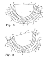
- the shaft 202 of the screw 18 and the end walls 132 and 134 of the shaft receiving slot 122 cooperate to limit the angulation of the bearing positioner 14 relative to the shell 12 to between a neutral position, as shown, for example, in Fig. 3 , to a 20° angulated position, as shown for example in Figs. 1 and 2 .
- the side walls 126, 128 and end walls 132, 136 extend inwardly from the convex surface 102 of the bearing positioner 14 to a depth 144.
- the depth 144 is approximately 1.02 mm (0.040 inch).
- the head-receiving slot 124 of the screw-receiving slot 108 of the bearing positioner comprises a concavely curved side wall 146.
- the radius of curvature 148 of the concave wall 146 of the head-receiving slot 124 of the screw-receiving slot 108 of the bearing positioner 14 is approximately equal to the radius of curvature 216 of the convex side wall 214 of the head 200 of the screw 18.
- the curved side wall 146 extends between and couples the concave surface 104 and the fastener-receiving slot 122 of the bearing positioner 14.
- the head-receiving slot 124 has a depth 150 approximately equal to or greater than the maximum thickness 218 of the head 200 of the screw 18 so that the head 200 of the screw 18 does not interfere with positioning of the bearing 16 in the bearing positioner 14 when the screw 18 is used to secure the bearing positioner 14 to the shell 12.
- the rim wall 106 and concave surface 104 are formed to include a plurality of radially extending orientation notches 152.
- twelve orientation notches 152 extend into the rim wall 106 and concave surface 104 adjacent the junction of the rim wall 106 and concave surface 104.
- Each orientation notch 152 is equidistantly angularly displaced from each of its adjacent orientation notches 152.
- each orientation notch 152 is displaced from each of its adjacent orientation notches 152 by an angle 154. As shown, the angle 154 is approximately 30°
- Each orientation notch 152 is configured to receive a radially extending triangular orientation flange 99 extending from the concave surface 92 of the bearing 16.
- orientation notches 152 and flanges 99 are common in the prosthetic art and particularly in the acetabular cup assembly prosthetic art and will not be discussed in detail. Suitable orientation notches and flanges are disclosed in US-5935175 , US-5571198 , and US-5782928 .
- the screw 18 includes a head 200 and a shaft 202 on which a thread 204 is formed.
- the thread 204 is sized and configured to cooperate with the thread 84 of the attachment hole 80 so that screw 18 can be utilized to secure bearing positioner 14 to shell 12.
- the head 200 of the screw 18 includes a concave top surface 206, and a convexly curved side wall 214.
- the convexly curved side wall 214 extends between and couples the concave surface 206 of the head 200 to the shaft 202 of the screw 18.
- the entire screw 18 is formed concentrically (except for the threads 204) about a longitudinal axis 212.
- the concave face 206 of the head 200 has a radius of curvature 208 so that the surface lies below the concave surface 102 of the bearing positioner 14 when the screw 18 is received in the screw-receiving slot 108 of the bearing positioner 14 and the attachment hole 80 of the shell 12 and tightened.
- the radius of curvature 208 of the concave surface 206 of the head 200 is approximately 1.27 mm (0.5 inch).
- the head 200 of the screw 18 does not interfere with positioning of the bearing 16 within the bearing-receiving cavity 112 of the bearing positioner 14.
- the convexly curved side wall 214 of the head 200 of the screw 18 exhibits a radius of curvature 216.
- the radius of curvature 216 is approximately equal to the radius of curvature 148 of the concave wall 146 of the head-receiving slot 124 of the screw-receiving slot 108 of the bearing positioner 14.
- the shaft 202 of the screw has a diameter 210 slightly less than the displacement 130 between the side walls 126, 128 of the fastener-receiving slot 122 of the screw-receiving slot 108 of the bearing positioner 14. This allows the bearing positioner 14 to be angulated with respect to the shell 12 by sliding the shaft 202 of the screw 18 prior to tightening longitudinally within the fastener-receiving slot 122. This also facilitates rotation of the bearing positioner 14 about the screw 18 prior to tightening for rotational positioning of the bearing positioner 14 relative to the shell 12.
- the maximum thickness 218 of the head 200 of the screw 18 is approximately 3.8 mm (0.150 inch).
- the diameter 220 of the head of the screw 18 is approximately 13.6 mm (0.535 inch).
- the head 200 of the screw 18 may be formed to include structure to facilitate rotation and tightening of the screw 18.
- the head 200 of the screw 18 is formed to include a hex hole 224 formed concentrically about the axis 212.
- the hex hole 224 permits an instrument, such as an allen wrench or other hex shaped driver, to be utilized to tighten the screw 18.
- the screw 18 has a maximum length 222 selected to permit the shaft 202 to extend sufficiently far into the attachment hole 80 of the shell 12 when the head 200 is received in the head-receiving slot 124 of the screw-receiving slot 108 of the bearing positioner 14 to allow the bearing positioner 14 to be secured in its desired position relative to the shell 12.
- the maximum length 222 is approximately 0.89 mm (0.035 inch).
- the bearing 16 includes a convex surface 90 that has a generally semispherical portion 89 and a taper wall portion 91.
- the taper wall portion 91 forms a male taper configured to cooperate with the female taper of the bearing positioner 14 to aid in securing the bearing 16 in the bearing positioner 14.
- Bearing 16 also includes a concave bearing surface 92 that defines an opening 94 sized to receive a prosthetic femoral ball (not shown).
- a rim 96 extends circumferentially around opening 94 of bearing 16.
- Bearing 16 is symmetrical. It is understood, however, that bearing 16 of the present invention may be a non-symmetrical component.
- Bearing 16 is preferably made from a polymeric material such as ultra high molecular weight polyethylene (UHMWPE). Of course, bearing 16 could be made of other types of implantable bearing materials such as a metal material or a ceramic material.
- the illustrated bearing 16 is a neutral bearing of the type commonly available from DePuy Orthopedics Inc as a component of the acetabular cup system sold under the trade mark Pinnacle.
- Such a bearing 16 includes a variable interface prosthesis taper, which provides a locking mechanism for use with advanced hard bearing surfaces, such as that in the metal-on-metal systems sold under the trade mark Ultamet. The use of hard bearing surfaces holds the potential for reduced wear and greater longevity. If future revisions would be necessary, the variable interface prosthesis taper allows for exchange of the bearing 16 without exchanging a well-fixed shell 12.
- the bearing 16 is fitted within the cavity 112 of the bearing positioner 14 in a conventional manner.
- the triangular orientation flanges 99 on the bearing 16 may be aligned with orientation notches 152 of the bearing positioner 14 most closely positioned to the desired rotational orientation of the bearing 16 with respect to the bearing positioner 14.
- the bearing 16 and bearing positioner 14 are locked together in a conventional manner.
- the taper wall 120 of the bearing positioner 14 and the taper wall portion 91 of the bearing 16, acting as female and male tapers, respectively, cooperate to hold bearing 16 in position relative to the bearing positioner 14.
- the male taper of the bearing 16 engages the female taper of the bearing positioner 14 and forms a locking mechanical connection therebetween.
- Taper walls 120, 91 may be a straight taper, as in Figs. 2, 3 , 13 and 14 , or they may be as a curve of a conic section, for example circular, elliptical, parabolic, hyperbolic or the like. If taper of convex surface 90 of the bearing 16 is straight, taper of the concave surface 104 of the bearing positioner 14 is also straight.
- the described male and female tapers are machine tapers that provide a connection that ensures and maintains accurate alignment between bearing positioner 14 and the bearing 16 and permits bearing positioner 14 and the bearing 16 to be separated for reconditioning or for substitution of other parts.
- Tapers may be a self-holding taper (i.e. self-locking) or a self-releasing taper.
- the shell 12 is oriented within the bone in such a way as to maximize potential for short term stability and long term fixation without regard to the position of the concave surface 22.
- the bearing positioner 14 is then mechanically locked into the shell 12 at an angular and rotational position relative to the shell 12 to orient the concave bearing face 92 of the bearing 16 to be received in the bearing positioner 14 at a desired position to closely simulate the anatomical structure of the patient into which the acetabular cup assembly 10 is being implanted.
- the bearing 16 mechanically locks into the bearing positioner 14.
- the bearing positioner 14 mechanically locks to the shell 12 and the shell 12 attaches to the acetabulum with or without the aid or one or more adjunct fixation devices such as screws, spikes, flanges, bubbles, etc.
- the shell 12 is oriented within the bone in such a way as to maximize potential for short term stability and long term fixation irrespective of the face 92 position.
- the bearing positioner 14 is attached to the shell 12 and oriented in such a way as to optimize stability of the artificial joint and then is mechanically locked to the shell 12.
- the appropriate bearing 16 is selected and seated in the bearing positioner 14.
- the bearing positioner of the illustrated embodiments may also provide for adjustment of the center of articulation of the bearing within the positioner. It is thus contemplated that the bearing positioner may be lateralized so that the concave surface on which the bearing 16 articulates is shifted laterally relative to the outer surface that engages the shell 12.
- a lateralized bearing positioner 14' includes an outer convex surface 102 and an inner concave surface 104 that are identical to the like surfaces on the positioner 14 shown in Figs. 13 and 14 .
- the remaining engagement features of the bearing positioner can be the same as described above, such as the inner semispherical and tapered portions and orientation notches.
- the radius of curvature 117 of the semispherical portion 118 is unchanged after the lateralization of the bearing positioner 14'.
- the focus 114' of this radius of curvature 117 is offset from the focus 114 from which the radius of curvature 116 of the outer convex surface 102 is measured.
- This lateralization of the bearing positioner is also manifested in an increase in the depth 144' of the fastener-receiving slot 122', as well as the overall height of the positioner. It can thus be appreciated that the thickness of the bearing positioner is increased at the slot 122' to laterally offset the interior engagement features of the positioner 14'. It can be appreciated that the amount of lateralization shown in Fig. 17 has been exaggerated for clarity. In practice, alternative bearing positioners 14' maybe provided with increasing heights in increments of 0.25 mm (0.010 inch) to accommodate small variations in joint anatomy between patients.
- the bearing positioner 14 can be oriented at any angle within a range (in the illustrated embodiment up to twenty degrees from a neutral position) relative to the shell 12 and can be oriented rotationally relative to the shell 12 in any position.
- the options for relative position between the bearing positioner 14 and the shell 12 can be infinite or can be predefined to a finite number of positions (for example 5° increments).
- the concave surface 22 of the shell 12 and the convex surface 102 of the bearing positioner 14 are generally semispherical and hemispherical, respectively, in shape.
- the shell 12 contains a threaded apex attachment hole 80.
- the bearing positioner 14 contains an apex slot hole 108 that is elongated to one side of the axis 110 sufficiently to provide the desired amount of relative angular position between the shell 12 and the bearing positioner 14.
- the screw 18 passes through the screw-receiving slot 108 in the bearing positioner 14 and into the attachment hole 80 in the shell 12 to fasten the bearing positioner 14 to the shell 12.
- the bearing positioner 14 is able to angulate as allowed by the elongated slot 108 and can be positioned rotationally by rotating the bearing positioner 14 about the head 200 of the screw 18.
- the device 10 allows revision of well fixed cups with inadequate face positioning without disrupting the shell/bone interface and allows positioning of a new acetabular reconstructive device 10 where most advantageous for bone fixation and positioning of the bearing face 92 in the optimum position for stability, each independent of the other.
- hemispherical and “semispherical” are used in this specification to refer to hemispherical and semispherical ranges conventionally used in acetabular and glenoid shells, liners, and cup bearings including less than hemispherical and, in some cases, more than hemispherical.
- Shell 1712 is substantially similar to shell 12 and thus identical components will not be described in detail.
- Shell 1712 includes a bone facing surface 1752 that does not include the lips 58 and 60 that define the attachment channel 40 present in shell 12.
- illustrated shell 1712 includes a single attachment hole 1768 (obscured by flange 1702) for attachment of an adjunct attachment device 1700 thereto.
- the adjunct attachment device 1700 is of a type commonly used with acetabular prosthesis to facilitate attachment of the prosthesis to the hip of a patient in a location optimal for stable attachment of the shell 12 in the acetabulum.
- Other attachment devices 1700 can be used, whether unmodified or with slight modification, with the disclosed shells 12, 1712 and 1812 of the acetabular cup assemblies 10, 1810 described above.
- Fig. 19 is a perspective view of a second embodiment of an acetabular cup assembly 1810.
- acetabular cup assembly 1810 facilitates attachment of the shell component 1812 to the patient in an optimal location to facilitate stability of the assembly 1810 without regard to the desired location of the bearing face 92 of the bearing 1816.
- the acetabular cup assembly 1810 includes a shell 1812, a bearing positioner 1814, a bearing 1816 and a set screw 1818.
- the bearing 1816 is very similar to bearing 16 described above, except that bearing 16 is a neutral bearing whereas bearing 1816 is configured to provide medial or lateral alteration of the bearing face 1892.
- Bearing 1816 is of the type of bearing commonly available from DePuy Orthopaedics Inc as a component of the acetabular cup system sold under the trade mark Pinnacle.
- Shell 1812 is somewhat similar to shell 12. While shell 1812 is not shown as including any attachment feature 32, it can be provided with any of the attachment features 32 discussed above with regard to shell 12 or shell 1712.
- Shell 1812 includes diametrically opposed orientation flanges 1817, 1819 extending distally from the rim 1844 of the shell 1812.
- the inner surfaces 1821 of the orientation flanges 1817, 1819 have a radius of curvature identical to the radius of curvature 28 (not shown in Fig. 19 but similar to that shown in Figs. 5 and 6 ) of the concave surface 22 (not shown in Fig. 19 but similar to that shown in Figs. 5 and 6 ) of shell 1812.
- Each flange 1817, 1819 includes a slot 1823 extending equatorially partially along the length of the flange 1817, 1819.
- Each slot 1823 is configured to receive a tang 1911 (only one of which is visible in Fig. 19 ) extending from the convex surface 102 of the bearing positioner 1814.
- Each tang 1911 extends radially from the convex surface 102 of the bearing positioner 14 and is diametrically opposed to the other tang 1911.
- the slots 1823 in flanges 1817, 1819 and tangs 1911 are configured to allow the tangs 1911 to move longitudinally within the slots 1823 to facilitate angular adjustment of the bearing positioner 1814 relative to the shell 1812.
- the bearing positioner 1814 can not be positioned rotationally relative to the shell 1812. Rotational positioning of the bearing positioner 1814 can be accomplished through rotation of the combined shell 1812 and bearing positioner 1814 subassembly.
- a flange 1825 extends distally from the rim 44 of the shell 1812.
- the flange 1825 is configured to include a set screw-receiving hole 1827 extending therethrough within which a set screw 1818 is received.
- the set screw 1818 is tightened to fix the relative positions of the bearing positioner 1814 and shell 1812.
- acetabular cup systems include an apex hole, either configured for receipt of a bone screw or for attaching a bearing directly or indirectly to the shell and a semispherical or hemispherical concave surface.
- the bearing positioner 14 and bearing 16 provided by the invention can be used to replace a worn or misaligned bearing received in such a prior art shell.
- the acetabular component of an existing hip prosthesis can be refurbished without the need of removing the prior art shell.
- the bearings 16, 1816 described above are interchangeable and either of them may be used with any of the bearing positioners 14, 1814 described above.
- the acetabular cup assembly 1810 is used in much the same manner as described above with regard to acetabular cup assembly 10.
Abstract
Description
- The present invention is directed to a prosthetic cup assembly for use in a hip prosthesis and more particularly to such an assembly that permits the prosthesis to be implanted at a desirable fixation point in the hip while allowing the face of the bearing surface to be oriented independently of the implant position within the acetabulum.
-
US-5049158 discloses an acetabular cup assembly which includes a metal shell component for attachment to an acetabulum to replace the natural socket and a bearing component (commonly made of plastic, metal or ceramic) that is inserted into the shell to provide a bearing surface for receiving a femur ball prosthesis element or the proximal end of the femur head. -
US-5282864 andUS-5413603 disclose bearing components which include a built-up lip around a portion of the bearing surface. - A problem that can occur with certain known acetabular cup assemblies is that they are configured so that the shell needs to be implanted in a very specific location in the acetabulum in order for the bearing surface to present a desirable surface for the head of the femur ball prosthesis to ride against in order to simulate the patient's natural anatomical structure and range of motion.
- Some acetabular cup assembly designs have used a third member as a way to maintain macrostability of the assembly parts while maintaining dome loading. Dome loading designs essentially ensure contact in the dome region by leaving clearance under the lip of the liner. These dome loading designs however, cause the insert to seat in the direction of the applied load.
- The shape and orientation of the concave face of the acetabular shell and the shape of the convex mating surface of the bearing received therein establish the orientation of the bearing face of the bearing when it is received in the acetabular shell. Once an acetabular shell is fixed in place, the orientation of the concave face of the acetabular shell, and therefore the bearing face of the bearing, can not be changed without disrupting the bone shell interface. Face changing liners made from polymeric materials can offer some measure of adjustment, but this option is not available for all bearings. The bearing face position is largely dictated by the position of the shell since typically they cannot be positioned independent of one another.
- Two currently available ways to change the bearing face orientation of the bearing is to use a face changing bearing (if available) or remove the shell thereby disrupting the shell bone interface, and repositioning the shell. Face changing liners do not always offer enough change.
- The invention provides a bearing positioner for an acetabular reconstruction device including a shell and a bearing that positions the bearing independent of the shell position.
- In one aspect, the invention provides an acetabular prosthetic device for attachment to a hip which comprises a shell, a bearing positioner and a position fixation device. The shell is configured for attachment to the hip and includes a concave surface configured to face away from the hip. The concave surface defines a bearing positioner-receiving cavity. The bearing positioner includes a convex surface and a concave surface. The convex surface is configured to be received in the bearing positioner-receiving cavity and oriented in multiple angular positions relative to the shell. The concave surface faces in the opposite direction as the convex surface and defines a bearing-receiving cavity. The position fixation device is configured to affix the bearing positioner to the shell in a selected position of the multiple angular positions.
- In another aspect, the invention provides a bearing positioner for use with a bearing having a convex surface and an oppositely facing bearing surface configured to bear against a first bone of a joint or prosthetic replacement for a portion of the first bone, and a prosthetic component configured for attachment to a second bone of the joint which prosthetic component includes a bone facing surface configured to face the second bone and a concave surface facing away from the bone facing surface and defining a cavity.
- The bearing positioner comprises an external convex surface and an internal concave surface. The external convex surface has a shape configured to be received in the cavity in multiple orientations and to bear and be secured against the concave surface of the prosthetic component when in any orientation selected from the multiple orientations. The internal concave surface defines a bearing-receiving cavity configured to receive a portion of the convex surface of the bearing therein and configured to orient the bearing surface of the bearing to bear against the first bone of the joint or the prosthetic replacement for the first bone when the external convex surface of the bearing positioner is secured in an orientation selected from the multiple orientations.
- In a further aspect, the invention provides a method of assembling a prosthetic component assembly, which includes: (a) providing a shell having a cavity with an inner surface, the inner surface having a shape; (b) providing a bearing positioner having an outer surface with a shape corresponding to the shape of the inner surface of the shell and an oppositely facing concave surface defining a bearing-receiving cavity; (c) inserting a portion of the bearing positioner into the cavity of the shell; (d) angulating the bearing positioner relative to the shell after inserting the portion of the bearing positioner into the shell to position the bearing positioner in a desired angular relationship relative to the shell; (e) securing the bearing positioner to the shell in the desired angular relationship relative to the shell; (f) providing a bearing having a convex surface configured for receipt in the bearing-receiving cavity and an oppositely facing bearing surface configured to engage and allow a head of a bone or a prosthetic replacement for a head of a bone to articulate against it; and (g) inserting the bearing into the bearing-receiving cavity so that at least a portion of the convex surface of the bearing engages at least a portion of the concave surface of the bearing positioner and the bearing surface is oriented to facilitate articulation of the head of a bone or a prosthetic replacement for a head of a bone to articulate against it when the bearing positioner is secured to the shell in the desired angular relationship relative to the shell.
- The invention can permit mechanical attachment of the bearing to the shell of a prosthetic joint component with the position of the bearing relative to the shell being capable of selective adjustment. The bearing may be angled with a fixed range of angles relative to the shell surface, the high point of the angled bearing face may be infinitely positioned rotationally about an axis perpendicular to the shell surface, and the centre of articulation of the bearing may be positioned at a pre-determined distance away from the outside surface of the shell. The bearing positioner can provides these three positioning characteristics. With respect to the latter positioning characteristic, adjustment of the location of the centre of articulation may be accomplished by lateralization of the internal concave surface.
- The bearing positioners allow the shell to be fixed to the bone in the optimal position for bone/shell attachment, and the bearing to be placed in the optimal position for hip biomechanics, all independent of each other. The bearing positioners allow positioning of the bearing relative to the shell in three distinct ways: 1) the bearing face may be angled within a fixed range relative to the shell interior surface; 2) the high point of the angled bearing face may be infinitely positioned rotationally about an axis perpendicular to the shell interior surface; and the bearing articulation centre or focus may be positioned at predefined distances from the centre or focus of the shell outer surface.
- Embodiments of the invention are described below by way of example with reference to the accompanying drawings, in which:
-
Fig. 1 is a perspective view of an acetabular cup assembly including a first embodiment of a shell, a first embodiment of a bearing positioner and a first embodiment of a bearing with the bearing positioner positioned relative to the shell to position a face of the bearing at approximately a twenty degree angular offset relative to a neutral position; -
Fig. 2 is a sectional view of the acetabular cup assembly ofFig. 1 showing with the bearing positioner positioned relative to the shell to position a face of the bearing at approximately a twenty degree angular offset relative to a neutral position; -
Fig. 3 is a sectional view of the acetabular cup assembly ofFig. 1 showing with the bearing positioner positioned relative to the shell to position a face of the bearing at a neutral position; -
Fig. 4 is a plan view of the shell of the acetabular cup assembly ofFig. 1 ; -
Fig. 5 is a sectional view along line 5-5 of the shell ofFig. 4 ; -
Fig. 6 is a sectional view along line 6-6 of the shell ofFig. 4 ; -
Fig. 7 is a view of that portion of the shell enclosed incircle 7 inFig. 5 ; -
Fig. 8 is a view of that portion of the shell enclosed in circle 8 inFig. 5 ; -
Fig. 9 is a view of that portion of the shell enclosed in circle 9 inFig. 6 ; -
Fig. 10 is a plan view of the bearing positioner ofFig. 1 ; -
Fig. 11 is a side elevation view of the bearing positioner ofFig. 10 ; -
Fig. 12 is a plan view of the bearing positioner ofFig. 10 ; -
Fig. 13 is a sectional view along line 13-13 of the bearing positioner ofFig. 10 ; -
Fig. 14 is a sectional view along line 14-14 of the bearing positioner ofFig. 10 ; -
Fig. 15 is a plan view of the screw of the acetabular cup assembly ofFig. 1 ; -
Fig. 16 is a sectional view taken along the line 16-16 of the screw ofFig. 15 ; -
Fig. 17 is a sectional view of a bearing positioner similar toFig. 13 in which the bearing positioner has been lateralized. -
Fig. 18 is a perspective view of a second embodiment of a shell for use with the acetabular cup assembly ofFig. 1 and an attachment bracket configured to facilitate attachment of the shell to the hip of a patient; -
Fig. 19 is a perspective view of a second embodiment of an acetabular cup assembly showing a third embodiment of a shell, a second embodiment of a bearing positioner and a second embodiment of a bearing. - Referring to the drawings,
Figs 1 to 16 show an acetabular reconstruction device orprosthesis 10 which includes a shell orhub 12, abearing positioner 14, abearing 16 and ascrew 18. While only asingle hub 12,bearing positioner 14 andbearing 16 is shown, a plurality of differently sized and configuredshells 12,bearing positioners 14 andbearings 16 may be provided to facilitate matching the components with the anatomy of the patient into which theprosthesis 10 will be implanted. - For instance, it is a common practice to provide multiple differently configured bearings that are each adapted to mate with a single shell to provide different positional orientation of the face of the bearing when the bearing is received in the shell. Similarly, multiple differently configured
bearings 16 might be provided that are each adapted to mate withrespective bearing positioners 14 to provide different positional orientation of the face of thebearing 16 when thebearing 16 is received in thebearing positioner 14. Thebearing 16 shown in the drawings should be considered to be a "neutral" bearing 16 providing a face orientation consistent with a common anatomical structure of a patient. - Similarly, multiple differently configured shells can be provided, each sized to provide optimal bone to prosthesis contact for a common size of hip bone. The
shell 12 shown in the drawings should be considered as anexemplary shell 12 configured for implantation into a standard sized hip. Differently sizedshells 12 may be provided for use with patients having differently sized hips. - In the illustrated embodiment, the
shell 12 includes anexternal convex surface 20 and an internalconcave surface 22. Theconvex surface 20 andconcave surface 22 are illustratively, at least in part, semispherical, i.e. substantial portions of the surface are equidistant from afocus 24. Illustratively, thesemispherical portion 21 of theconvex surface 20 and the semisphericalconcave surface 22 are each formed about acommon focus 24. In the illustrated embodiment, thesemispherical portion 21 of theconvex surface 20 exhibits a radius of curvature 26 and the semisphericalconcave surface 22 exhibits a radius ofcurvature 28 differing from the radius of curvature 26 of thesemispherical portion 21 of theconvex surface 20. - The radius of curvature 26 of the
semispherical portion 21 of theconvex surface 20 is sized to approximate the curvature of the acetabulum of the hip of the patient into which theacetabular prosthesis 10 is to be implanted. In the illustrated embodiment, the radius of curvature 26 of thesemispherical portion 21 of theconvex surface 20 is approximately 30.4 mm (1.20 inch). As mentioned previously, multiple differently configuredshells 12 might be provided, in which thesemispherical portions 21 of theconvex surface 20 have different radii of curvature 26 so that the surgeon can select ashell 12 for implantation that will have the optimal configuration for stably implanting theshell 12 in the hip of the patient. Also, the external convex surface of theshell 12 can have a different shape which would facilitate implantation into the hip of the patient and such surface shape is not limited to including a semispherical portion. - The radius of
curvature 28 of the semisphericalconcave surface 22 is sized to approximate the curvature of an externalconvex surface 102 of a bearingpositioner 14, to facilitate mating of the bearingpositioner 14 to theshell 12. Sincemultiple bearing positioners 14 can be provided, having a differently sizedconvex surfaces 102, the radius ofcurvature 28 of theconcave surface 22 can varied according to the curvature of the correspondingconvex surface 102 of the bearingpositioner 14 with which theshell 12 is to mate. The radius ofcurvature 28 of the semisphericalconcave surface 22 of theshell 12 shown in the drawings is approximately 27.3 mm (1.07 inch) to facilitate mating with the bearingpositioner 14. - The
concave surface 22 of theshell 12 defines acavity 30 which is configured to receive a portion of a bearingpositioner 14 for mating to form a portion of theacetabular prosthesis 10. While being described as aconcave surface 22, theshell 12 can include a differently sized and shaped surface configured to facilitate mating the bearingpositioner 14 to theshell 12. For instance themating surface 22 of theshell 12 may be convex and be configured to mate with aconcave mating surface 102 of a bearingpositioner 14. Theconcave surface 22 is described as being semispherical as this shape appears to provide the optimal shape to permit theshell 12 to mate with a bearingpositioner 14 having a hemispherically shapedconvex mating surface 102 while permitting the bearingpositioner 14 to be oriented in different positions relative to theshell 12 as will be explained further below. - The
shell 12 is configured for attachment to the acetabulum. Theshell 12 attaches to the acetabulum with or without the aid or one or more fixation devices such as screws, spikes, flanges, bubbles, etc. Theshell 12 shown in the drawings includes attachment features 32 configured to facilitate attachment of theshell 12 to an acetabulum. Among the illustrated attachment features 32 are a bubbledsurface 34, a plurality ofbone screw apertures 36, a plurality of in-growth apertures 38 and an annularly extending fixationdevice attachment channel 40. Any of theshells US-4883491 ,US-5226917 ,US-5310408 ,US-5358532 ,US-5658347 andUS-5702477 . - The
convex surface 20 of theshell 12 is textured with a bubbled orporous coating 34 to facilitate securingshell 12 in place within an appropriately prepared acetabulum. Theporous coating 34 is configured to facilitate biological ingrowth of a patient's bone within the outer surface of theshell 12 whereby long-term fixation of theshell 12 to the patient's bone may be achieved. A number of spikes (not shown) may be secured to the outer surface of theshell 12 to further facilitate fixation of theshell 12 to the patient's bone as is well known in the art. A bubbled orporous coating 34 can be used to facilitate bone ingrowth and on-growth with the implantedshell 12. In the illustrated embodiment,shell 12 is preferably made from titanium, but may be made from a cobalt chrome material or other suitable materials. The type ofporous coating 34 utilized is selected from those coating materials known to adhere or bond well to the material from which theshell 12 is fabricated. Alternatively, theshell 12 may be sand blasted or otherwise roughened to provide thetextured finish 34. - The
shell 12 includes a plurality of bone screw holes 36 (illustratively six) extending between theconvex surface 20 and theconcave surface 22. The bone screw holes 36 are configured to receive bone screws for securing theshell 12 to the hip of the patient in a known manner. The bone screw holes 36 are also configured to receive the head of a bone screw therein with the head positioned to avoid interference with orientation of the bearingpositioner 14 within the bearing positioner-receivingcavity 30. Therefore, as shown, for example, inFig. 9 , adjacent theconcave surface 22, the bone screw holes 36 are formed to include afeature 41, such as a countersink, to permit the head of the bone screw to be seated below theconcave surface 22 of theshell 12. - In the illustrated embodiment, the six bone screw holes 36 are positioned equidistantly (60° apart) around the
shell 12. The bone screw holes 36 are each displaced by thesame angle 42 from therim 44 of theshell 12. Preferably, theangle 42 is approximately 60°. Utilization of bone screw holes and bone screws for attachment of acetabular components to the hip of a patient is described inUS-5571198 . If a bone screw is not received in abone screw hole 36 of an implantedshell 12, thebone screw hole 36 may act as a situs for bone in-growth to help secure theshell 12 to the hip. - The
rim 44 is provided by a substantially planar wall extending between theconvex surface 20 and theconcave surface 22 perpendicular to theaxis 82 of theshell 12. Therim 44 is displaced from thefocus 24 by adisplacement 45. In the illustrated embodiment, the displacement is approximately 0.273 inches. - The
shell 12 includes a plurality of in-growth apertures 38 (preferably six) extending between theconvex surface 20 and theconcave surface 22. The plurality ofingrowth apertures 38 are configured to allow the bone of a patient to grow therein to facilitate increased stability of theimplant 10. As shown, for example, inFig. 8 , thewalls 46 defining each of the plurality of in-growth apertures 38 are not cylindrically formed about theaxis 48 of theaperture 38 but rather are concave with respect to theaxis 48. The concavity of thesewalls 46 facilitates bone attachment to theshell 12 during in-growth into the plurality of in-growth apertures 38. - Any of the plurality of in-
growth apertures 38 could alternatively be used as sites through which other fixation devices such as bone screws or pins are extended or bone cement is received to aid in securing theshell 12 in the desired location in the hip of the patient in a known manner. In the illustrated embodiment, the six in-growth apertures 38 are positioned equidistantly (60° apart) around theshell 12 and are angularly displaced by 30° from each adjacentbone screw hole 36. Each of the in-growth apertures 38 is displaced by thesame angle 50 from therim 44 of theshell 12. As shown, theangle 50 is approximately 42°. - The
bone facing surface 52 of theshell 12 has been described only with regard to the outerconvex surface 20 which has been described as having asemispherical portion 21. Thebone facing surface 52 of theshell 12 also includes acylindrical wall portion 54, atransition region 56, a proximal annular outwardly extendinglip 58 and a distal annular outwardly extendinglip 60. Thetransition region 56 extends between thesemispherical portion 21 of theconvex surface 20 and theproximal lip 58 to provide a smooth transition between those features. - The proximal and
distal lips cylindrical wall portion 54 of thebone facing surface 52. Theinner wall 62 of theproximal lip 58, theinner wall 64 of thedistal lip 60 and thecylindrical wall portion 54 cooperate to define the fixationdevice attachment channel 40. As shown, for example, inFig. 7 , theinner wall 62 of theproximal lip 58 and theinner wall 64 of thedistal lip 60 slant away from each other as they extend from thecylindrical wall 54 to form ataper 66. Illustratively, thetaper 66 between theinner walls lips taper 66 is provided to facilitate stable seating of anattachment flange 1702 of afixation device 1700 such as that which is shown inFig. 18 attached to the second embodiment of ashell 1712. - A plurality of attachment holes 68 extend between the
cylindrical wall 54 and theconcave surface 22 of theshell 12 to facilitate attachment of anadjunct fixation device 1700 to theshell 12. Adjacent theconcave surface 22, each attachment hole is configured to include a counter bore 70 having acylindrical wall 72 sized to receive the head of afastener 1701 which seats against a ring shapedwall 74 extending between thecylindrical wall 72 and ashaft aperture 76. Adjacent thecylindrical wall portion 54 of thebone facing surface 52, eachattachment hole 68 is formed to include acounter sink 78. When anadjunct fixation device 1700 is utilized withshell 12, thefastener 1701 is inserted into theattachment hole 68 so that the head is received in thecounterbore 70 so as to not interfere with orientation of the bearingpositioner 14 within the bearing positioner-receivingcavity 30. The threaded shaft of thefastener 1701 extends through theshaft aperture 76 and threadingly engages an internal thread formed in anattachment hole 1704 extending through theattachment flange 1702 of theadjunct fixation device 1700. - The
shell 12 is formed to include a threaded bearingpositioner attachment hole 80 extending between theconcave surface 22 and theconvex surface 20. The bearingpositioner attachment hole 80 is an apex hole formed concentrically about theaxis 82 of theshell 12. The bearingpositioner attachment hole 80 is sized to receive theshaft 202 of thescrew 18 therein to secure the bearingpositioner 14 within theshell 12. The thread 84 of the bearingpositioner attachment hole 80 is a conformal thread to thethread 204 on theshaft 202 of thescrew 18. - As shown, for example, in
Figs. 1 ,2 ,3 and10 to 14 , the bearingpositioner 14 includes aconvex surface 102, aconcave surface 104, and arim wall 106 formed generally concentrically about anaxis 110 and a screw-receivingslot 108. The bearingpositioner 14 is preferably made from titanium, but may be made from a cobalt chrome material, or other suitable materials. Theconcave surface 104 defines a bearing-receivingcavity 112 configured to receive a portion of the bearing 16 therein. In the illustrated embodiment, therim wall 106 extends between and couples theconcave surface 104 and theconvex surface 102. - The
convex surface 102 is generally hemispherical and is formed concentrically about afocus 114. Theconvex surface 102 is sized and shaped to be received, at least in part, within the bearing positioner-receivingcavity 30 of theshell 12 and to allow the bearingpositioner 14 to be oriented in a desired position with respect to theshell 12. Since the illustratedbearing positioner 14 is configured for use with the illustratedshell 12, the radius ofcurvature 116 of theconvex surface 102 is approximately equal to the radius ofcurvature 28 of theconcave surface 22 of theshell 12. In the illustrated embodiment, the radius ofcurvature 116 of theconvex surface 102 is approximately 27.4 mm (1.078 inch). - The stated radius of
curvature 116 of theconvex surface 102 is slightly greater(for example about 0.13 mm (0.005 inch) greater) than the stated radius ofcurvature 28 of theconcave surface 22 of theshell 12. This slight difference between the radius ofcurvature 116 and the radius ofcurvature 28 induces the bearingpositioner 14 to seat along a narrow equatorial strip of both theconvex surface 102 of the bearingpositioner 14 and theconcave surface 22 of theshell 12 when thescrew 18 urges theconvex surface 102 into engagement with theconcave surface 22. Since the radius ofcurvature 116 of theconvex surface 102 of the bearingpositioner 14 is somewhat larger than the radius ofcurvature 28 of theconcave surface 22 of theshell 12, the equator regions of the two components load when thescrew 18 is tightened maintaining a stable interface with little relative motion between theshell 12 and the bearingpositioner 14. - The
concave surface 104 of the bearingpositioner 14 comprises asemispherical portion 118 at a radius ofcurvature 117 and atapered portion 120 both formed concentrically about theaxis 110. The taperedportion 120 extends between and couples thesemispherical portion 118 of theconcave surface 104 and therim wall 106. Therim wall 106 defines a plane through which thebearing 16 enters thecavity 112 of bearingpositioner 14 formed byconcave surface 104. The taperedportion 120 forms a female taper having ataper 121. The female taper extends around the entire periphery ofcavity 112 adjacent therim wall 106. It is understood that the axial depth of female taper withincavity 112 may vary. In the illustrated embodiment thetaper 121 is approximately 10° and is configured to mate with a corresponding male taper on thebearing 16. - The bearing
positioner 14 contains an apex hole that is elongated to one side sufficient to form the screw-receivingslot 108 to provide the desired amount of relative angular position between theshell 12 and the bearingpositioner 14. When thescrew 18 passes through screw-receivingslot 108 in the bearingpositioner 14 and theattachment hole 80 in theshell 12, the bearingpositioner 14 is able to angulate as allowed by the screw-receivingslot 108 and can be positioned rotationally by rotating about thehead 200 of thescrew 18. Such rotational positioning is accomplished by rotating the bearingpositioner 14 about theaxis 82 of theshell 12 which coincides with theaxis 212 of thescrew 18 when theshaft 202 of thescrew 18 is received in theattachment aperture 80 of theshell 12. - The screw-receiving
slot 108 is configured to permit approximately 20° of angulation of the bearingpositioner 14 relative to theshell 12. The screw-receivingslot 108 comprises a fastener-receivingslot 122 and a head-receivingslot 124. - The fastener-receiving
slot 122 includes a firstplanar side wall 126 spaced apart from a secondplanar side wall 128 by adisplacement 130. Preferably, thedisplacement 130 is approximately equal to, or slightly greater than thediameter 210 of theshaft 202 of thescrew 18 to allow theshaft 202 of thescrew 18 to slide therein. The fastener-receivingslot 122 includes a firstsemi-cylindrical end wall 132 coupling one end of the firstplanar side wall 126 to the secondplanar side wall 128. The firstsemicylindrical end wall 132 has a radius ofcurvature 134 approximately equal to one half thediameter 210 of theshaft 202 of thescrew 18 and is formed concentrically about theaxis 110 of the bearingpositioner 14. The fastener-receivingslot 122 includes a secondsemi-cylindrical end wall 136 coupling the other end of the firstplanar side wall 126 to the secondplanar side wall 128. The secondsemicylindrical end wall 136 has a radius ofcurvature 138 approximately equal to one half thediameter 210 of theshaft 202 of thescrew 18 and is formed concentrically about anaxis 140 extending radially from thefocus 114 of the bearingpositioner 14 at anangle 142. In the illustrated embodiment, theangle 142 is approximately 20 °. - Thus the
shaft 202 of thescrew 18 and theend walls shaft receiving slot 122 cooperate to limit the angulation of the bearingpositioner 14 relative to theshell 12 to between a neutral position, as shown, for example, inFig. 3 , to a 20° angulated position, as shown for example inFigs. 1 and2 . Theside walls walls convex surface 102 of the bearingpositioner 14 to adepth 144. Preferably, thedepth 144 is approximately 1.02 mm (0.040 inch). - The head-receiving
slot 124 of the screw-receivingslot 108 of the bearing positioner comprises a concavelycurved side wall 146. The radius ofcurvature 148 of theconcave wall 146 of the head-receivingslot 124 of the screw-receivingslot 108 of the bearingpositioner 14 is approximately equal to the radius ofcurvature 216 of theconvex side wall 214 of thehead 200 of thescrew 18. Thecurved side wall 146 extends between and couples theconcave surface 104 and the fastener-receivingslot 122 of the bearingpositioner 14. The head-receivingslot 124 has adepth 150 approximately equal to or greater than the maximum thickness 218 of thehead 200 of thescrew 18 so that thehead 200 of thescrew 18 does not interfere with positioning of the bearing 16 in the bearingpositioner 14 when thescrew 18 is used to secure the bearingpositioner 14 to theshell 12. - The
rim wall 106 andconcave surface 104 are formed to include a plurality of radially extendingorientation notches 152. Preferably, twelveorientation notches 152 extend into therim wall 106 andconcave surface 104 adjacent the junction of therim wall 106 andconcave surface 104. Eachorientation notch 152 is equidistantly angularly displaced from each of itsadjacent orientation notches 152. Thus, in the illustrated embodiment, eachorientation notch 152 is displaced from each of itsadjacent orientation notches 152 by anangle 154. As shown, theangle 154 is approximately 30° - Each
orientation notch 152 is configured to receive a radially extendingtriangular orientation flange 99 extending from theconcave surface 92 of thebearing 16. The use oforientation notches 152 andflanges 99 is common in the prosthetic art and particularly in the acetabular cup assembly prosthetic art and will not be discussed in detail. Suitable orientation notches and flanges are disclosed inUS-5935175 ,US-5571198 , andUS-5782928 . - As shown, for example, in
Figs. 2, 3 ,15 and 16 , thescrew 18 includes ahead 200 and ashaft 202 on which athread 204 is formed. As previously stated, thethread 204 is sized and configured to cooperate with the thread 84 of theattachment hole 80 so thatscrew 18 can be utilized to securebearing positioner 14 to shell 12. Thehead 200 of thescrew 18 includes a concavetop surface 206, and a convexlycurved side wall 214. The convexlycurved side wall 214 extends between and couples theconcave surface 206 of thehead 200 to theshaft 202 of thescrew 18. Theentire screw 18 is formed concentrically (except for the threads 204) about alongitudinal axis 212. Theconcave face 206 of thehead 200 has a radius ofcurvature 208 so that the surface lies below theconcave surface 102 of the bearingpositioner 14 when thescrew 18 is received in the screw-receivingslot 108 of the bearingpositioner 14 and theattachment hole 80 of theshell 12 and tightened. In the illustrated embodiment, the radius ofcurvature 208 of theconcave surface 206 of thehead 200 is approximately 1.27 mm (0.5 inch). Thus, thehead 200 of thescrew 18 does not interfere with positioning of thebearing 16 within the bearing-receivingcavity 112 of the bearingpositioner 14. - The convexly
curved side wall 214 of thehead 200 of thescrew 18 exhibits a radius ofcurvature 216. The radius ofcurvature 216 is approximately equal to the radius ofcurvature 148 of theconcave wall 146 of the head-receivingslot 124 of the screw-receivingslot 108 of the bearingpositioner 14. Thus, when thescrew 18 is received in the screw-receivingslot 108 and tightened, portions of theconvex side wall 214 of thehead 200 of thescrew 18 engage the concavelycurved wall 146 of the head-receivingslot 124 of the screw-receivingslot 108 of the bearingpositioner 14 along contiguous surface areas. This aids in securely fastening the bearingpositioner 14 in its selected orientation relative to theshell 12. - The
shaft 202 of the screw has adiameter 210 slightly less than thedisplacement 130 between theside walls slot 122 of the screw-receivingslot 108 of the bearingpositioner 14. This allows the bearingpositioner 14 to be angulated with respect to theshell 12 by sliding theshaft 202 of thescrew 18 prior to tightening longitudinally within the fastener-receivingslot 122. This also facilitates rotation of the bearingpositioner 14 about thescrew 18 prior to tightening for rotational positioning of the bearingpositioner 14 relative to theshell 12. - The maximum thickness 218 of the
head 200 of thescrew 18 is approximately 3.8 mm (0.150 inch). The diameter 220 of the head of thescrew 18 is approximately 13.6 mm (0.535 inch). Thehead 200 of thescrew 18 may be formed to include structure to facilitate rotation and tightening of thescrew 18. In the illustrated embodiment, thehead 200 of thescrew 18 is formed to include a hex hole 224 formed concentrically about theaxis 212. The hex hole 224 permits an instrument, such as an allen wrench or other hex shaped driver, to be utilized to tighten thescrew 18. - The
screw 18 has a maximum length 222 selected to permit theshaft 202 to extend sufficiently far into theattachment hole 80 of theshell 12 when thehead 200 is received in the head-receivingslot 124 of the screw-receivingslot 108 of the bearingpositioner 14 to allow the bearingpositioner 14 to be secured in its desired position relative to theshell 12. In the illustrated embodiment, the maximum length 222 is approximately 0.89 mm (0.035 inch). - Referring to
Figs. 1 to 3 , thebearing 16 includes aconvex surface 90 that has a generallysemispherical portion 89 and ataper wall portion 91. Thetaper wall portion 91 forms a male taper configured to cooperate with the female taper of the bearingpositioner 14 to aid in securing thebearing 16 in the bearingpositioner 14.Bearing 16 also includes aconcave bearing surface 92 that defines anopening 94 sized to receive a prosthetic femoral ball (not shown). Arim 96 extends circumferentially around opening 94 ofbearing 16.Bearing 16 is symmetrical. It is understood, however, that bearing 16 of the present invention may be a non-symmetrical component.Bearing 16 is preferably made from a polymeric material such as ultra high molecular weight polyethylene (UHMWPE). Of course, bearing 16 could be made of other types of implantable bearing materials such as a metal material or a ceramic material. The illustratedbearing 16 is a neutral bearing of the type commonly available from DePuy Orthopedics Inc as a component of the acetabular cup system sold under the trade mark Pinnacle. Such abearing 16 includes a variable interface prosthesis taper, which provides a locking mechanism for use with advanced hard bearing surfaces, such as that in the metal-on-metal systems sold under the trade mark Ultamet. The use of hard bearing surfaces holds the potential for reduced wear and greater longevity. If future revisions would be necessary, the variable interface prosthesis taper allows for exchange of thebearing 16 without exchanging a well-fixedshell 12. - The
bearing 16 is fitted within thecavity 112 of the bearingpositioner 14 in a conventional manner. For instance, thetriangular orientation flanges 99 on thebearing 16 may be aligned withorientation notches 152 of the bearingpositioner 14 most closely positioned to the desired rotational orientation of the bearing 16 with respect to the bearingpositioner 14. Thebearing 16 and bearingpositioner 14 are locked together in a conventional manner. For instance, thetaper wall 120 of the bearingpositioner 14 and thetaper wall portion 91 of thebearing 16, acting as female and male tapers, respectively, cooperate to hold bearing 16 in position relative to the bearingpositioner 14. The male taper of thebearing 16 engages the female taper of the bearingpositioner 14 and forms a locking mechanical connection therebetween.Taper walls Figs. 2, 3 ,13 and 14 , or they may be as a curve of a conic section, for example circular, elliptical, parabolic, hyperbolic or the like. If taper ofconvex surface 90 of thebearing 16 is straight, taper of theconcave surface 104 of the bearingpositioner 14 is also straight. - The described male and female tapers are machine tapers that provide a connection that ensures and maintains accurate alignment between bearing
positioner 14 and thebearing 16 andpermits bearing positioner 14 and thebearing 16 to be separated for reconditioning or for substitution of other parts. Tapers may be a self-holding taper (i.e. self-locking) or a self-releasing taper. - In use, the
shell 12 is oriented within the bone in such a way as to maximize potential for short term stability and long term fixation without regard to the position of theconcave surface 22. The bearingpositioner 14 is then mechanically locked into theshell 12 at an angular and rotational position relative to theshell 12 to orient the concave bearing face 92 of thebearing 16 to be received in the bearingpositioner 14 at a desired position to closely simulate the anatomical structure of the patient into which theacetabular cup assembly 10 is being implanted. The bearing 16 mechanically locks into the bearingpositioner 14. The bearingpositioner 14 mechanically locks to theshell 12 and theshell 12 attaches to the acetabulum with or without the aid or one or more adjunct fixation devices such as screws, spikes, flanges, bubbles, etc. Theshell 12 is oriented within the bone in such a way as to maximize potential for short term stability and long term fixation irrespective of theface 92 position. After theshell 12 is fixed to the bone, the bearingpositioner 14 is attached to theshell 12 and oriented in such a way as to optimize stability of the artificial joint and then is mechanically locked to theshell 12. Next theappropriate bearing 16 is selected and seated in the bearingpositioner 14. - In addition to the adjustment of angular position accomplished as described above, the bearing positioner of the illustrated embodiments may also provide for adjustment of the center of articulation of the bearing within the positioner. It is thus contemplated that the bearing positioner may be lateralized so that the concave surface on which the
bearing 16 articulates is shifted laterally relative to the outer surface that engages theshell 12. In one example shown inFIG. 17 , a lateralized bearing positioner 14' includes an outerconvex surface 102 and an innerconcave surface 104 that are identical to the like surfaces on thepositioner 14 shown inFigs. 13 and 14 . Similarly, the remaining engagement features of the bearing positioner can be the same as described above, such as the inner semispherical and tapered portions and orientation notches. - Importantly, the radius of
curvature 117 of thesemispherical portion 118 is unchanged after the lateralization of the bearing positioner 14'. However, the focus 114' of this radius ofcurvature 117 is offset from thefocus 114 from which the radius ofcurvature 116 of the outerconvex surface 102 is measured. This lateralization of the bearing positioner is also manifested in an increase in the depth 144' of the fastener-receiving slot 122', as well as the overall height of the positioner. It can thus be appreciated that the thickness of the bearing positioner is increased at the slot 122' to laterally offset the interior engagement features of the positioner 14'. It can be appreciated that the amount of lateralization shown inFig. 17 has been exaggerated for clarity. In practice, alternative bearing positioners 14' maybe provided with increasing heights in increments of 0.25 mm (0.010 inch) to accommodate small variations in joint anatomy between patients. - The bearing
positioner 14 can be oriented at any angle within a range (in the illustrated embodiment up to twenty degrees from a neutral position) relative to theshell 12 and can be oriented rotationally relative to theshell 12 in any position. The options for relative position between the bearingpositioner 14 and theshell 12 can be infinite or can be predefined to a finite number of positions (for example 5° increments). - In the first embodiment of the
acetabular cup assembly 10, theconcave surface 22 of theshell 12 and theconvex surface 102 of the bearingpositioner 14 are generally semispherical and hemispherical, respectively, in shape. Theshell 12 contains a threadedapex attachment hole 80. The bearingpositioner 14 contains anapex slot hole 108 that is elongated to one side of theaxis 110 sufficiently to provide the desired amount of relative angular position between theshell 12 and the bearingpositioner 14. Thescrew 18 passes through the screw-receivingslot 108 in the bearingpositioner 14 and into theattachment hole 80 in theshell 12 to fasten the bearingpositioner 14 to theshell 12. The bearingpositioner 14 is able to angulate as allowed by theelongated slot 108 and can be positioned rotationally by rotating the bearingpositioner 14 about thehead 200 of thescrew 18. - The
device 10 allows revision of well fixed cups with inadequate face positioning without disrupting the shell/bone interface and allows positioning of a new acetabularreconstructive device 10 where most advantageous for bone fixation and positioning of the bearingface 92 in the optimum position for stability, each independent of the other. - The words "hemispherical" and "semispherical" are used in this specification to refer to hemispherical and semispherical ranges conventionally used in acetabular and glenoid shells, liners, and cup bearings including less than hemispherical and, in some cases, more than hemispherical.
- An alternative embodiment of
shell 1712 is illustrated inFig. 18 .Shell 1712 is substantially similar to shell 12 and thus identical components will not be described in detail.Shell 1712 includes abone facing surface 1752 that does not include thelips attachment channel 40 present inshell 12. Also, illustratedshell 1712 includes a single attachment hole 1768 (obscured by flange 1702) for attachment of anadjunct attachment device 1700 thereto. Theadjunct attachment device 1700 is of a type commonly used with acetabular prosthesis to facilitate attachment of the prosthesis to the hip of a patient in a location optimal for stable attachment of theshell 12 in the acetabulum.Other attachment devices 1700 can be used, whether unmodified or with slight modification, with the disclosedshells acetabular cup assemblies -
Fig. 19 is a perspective view of a second embodiment of anacetabular cup assembly 1810. Likeacetabular cup assembly 10,acetabular cup assembly 1810 facilitates attachment of theshell component 1812 to the patient in an optimal location to facilitate stability of theassembly 1810 without regard to the desired location of the bearingface 92 of thebearing 1816. Theacetabular cup assembly 1810 includes ashell 1812, abearing positioner 1814, abearing 1816 and aset screw 1818. Thebearing 1816 is very similar to bearing 16 described above, except that bearing 16 is a neutral bearing whereas bearing 1816 is configured to provide medial or lateral alteration of the bearing face 1892.Bearing 1816 is of the type of bearing commonly available from DePuy Orthopaedics Inc as a component of the acetabular cup system sold under the trade mark Pinnacle. -
Shell 1812 is somewhat similar toshell 12. Whileshell 1812 is not shown as including anyattachment feature 32, it can be provided with any of the attachment features 32 discussed above with regard to shell 12 orshell 1712.Shell 1812 includes diametrically opposedorientation flanges shell 1812. For example, theinner surfaces 1821 of theorientation flanges Fig. 19 but similar to that shown inFigs. 5 and 6 ) of the concave surface 22 (not shown inFig. 19 but similar to that shown inFigs. 5 and 6 ) ofshell 1812. - Each
flange slot 1823 extending equatorially partially along the length of theflange slot 1823 is configured to receive a tang 1911 (only one of which is visible inFig. 19 ) extending from theconvex surface 102 of thebearing positioner 1814. Eachtang 1911 extends radially from theconvex surface 102 of the bearingpositioner 14 and is diametrically opposed to theother tang 1911. Theslots 1823 inflanges tangs 1911 are configured to allow thetangs 1911 to move longitudinally within theslots 1823 to facilitate angular adjustment of thebearing positioner 1814 relative to theshell 1812. - Due to the presence of the
slots 1823,flanges tangs 1911, thebearing positioner 1814 can not be positioned rotationally relative to theshell 1812. Rotational positioning of thebearing positioner 1814 can be accomplished through rotation of the combinedshell 1812 andbearing positioner 1814 subassembly. - A
flange 1825 extends distally from therim 44 of theshell 1812. Theflange 1825 is configured to include a set screw-receiving hole 1827 extending therethrough within which aset screw 1818 is received. Upon angular rotation of thebearing positioner 1814 relative to theshell 1812, theset screw 1818 is tightened to fix the relative positions of thebearing positioner 1814 andshell 1812. - Many currently available shells for acetabular cup systems include an apex hole, either configured for receipt of a bone screw or for attaching a bearing directly or indirectly to the shell and a semispherical or hemispherical concave surface. Thus, using an appropriately configured screw capable of being secured within the apex hole of an existing prior art shell, the bearing
positioner 14 and bearing 16 provided by the invention can be used to replace a worn or misaligned bearing received in such a prior art shell. By using the disclosedbearing positioner 14 and bearing 16 to replace a worn or misaligned bearing, the acetabular component of an existing hip prosthesis can be refurbished without the need of removing the prior art shell. - The
bearings positioners acetabular cup assembly 1810 is used in much the same manner as described above with regard toacetabular cup assembly 10.
Claims (15)
- An acetabular prosthetic device for attachment to a hip comprising:a shell configured for attachment to the hip and including a concave surface defining a cavity configured to face away from the hip;a bearing positioner including a convex surface configured to be received within said cavity at multiple angular positions relative to the shell, and a concave surface facing in the opposite direction as the convex surface and defining a bearing-receiving cavity; anda position fixation device configured to affix the bearing positioner to the shell in a selected one of the multiple angular positions.
- The device of claim 1, in which the position fixation device includes a component of the shell and a component of the bearing positioner.
- The device of claim 2, in which the position fixation device includes a fastener having a shaft and an enlarged head, the component of the shell includes a hole sized to receive the shaft of the fastener and the component of the shell includes a slot having a length greater than a lateral dimension of the shaft so that prior to fixation of the bearing positioner to the shell the shaft can move along the length of the slot.
- The device of claim 1, in which the concave surface of the shell includes a semispherical portion having a radius of curvature and the convex surface of the bearing positioner includes a semispherical portion having a radius of curvature substantially similar to the radius of curvature of the semispherical portion of the concave surface of the shell.
- The device of claim 1, which includes a bearing having a convex surface and an oppositely facing concave surface defining a cavity for receiving a femoral head or a head of a prosthetic component replacing at least a portion of a femoral head and configured to allow a femoral head or head of a prosthetic component to articulate therein, in which the convex surface has a size and shape conforming to the size and shape of the concave surface of the bearing-receiving cavity to facilitate receipt of a portion of the convex surface of the bearing therein.
- The device of claim 3, in which the shaft of the fastener includes a screw thread, the attachment hole is threaded with a screw thread configured to cooperate with the screw thread of the fastener to facilitate tightening of the fastener, the slot in the bearing positioner includes a portion adjacent the convex surface configured to allow the shaft, but not the head, of the fastener to pass therethrough and a portion adjacent the concave surface configured to receive the head therein and having a wall configured to engage the head upon tightening of the screw to lock the bearing positioner in the one position relative to the shell.
- A bearing positioner for use with a bearing, the bearing having a convex surface and an oppositely facing bearing surface configured to bear against a first bone of a joint or prosthetic replacement for a portion of a first bone and a prosthetic component configured for attachment to a second bone of the joint which prosthetic component includes a bone facing surface configured to face the second bone and a concave surface facing away from the bone facing surface and defining a cavity, the bearing positioner comprising:an external convex surface having a shape configured to be received in the cavity in multiple orientations and to bear and be secured against the concave surface of the prosthetic component when in any orientation selected from the multiple orientations; andan internal concave surface defining a bearing-receiving cavity configured to receive a portion of the convex surface of the bearing therein and configured to orient the bearing surface of the bearing to bear against the first bone of the joint or the prosthetic replacement for the first bone when the external convex surface of the bearing positioner is secured in an orientation selected from the multiple orientations.
- The bearing positioner of claim 7, which includes a rim surface extending between and coupling the external convex surface and the internal concave surface, a slot displaced from the rim and extending between and coupling the external convex surface and the internal concave surface and a fastener having a threaded shaft configured to extend through the slot and to be received in a threaded hole in the prosthetic component.
- The bearing positioner of claim 8, in which the external convex surface includes a semicylindrical portion formed concentrically about a first focus along an axis of symmetry of the bearing positioner and exhibiting a radius of curvature, the internal concave surface includes a semicylindrical portion formed concentrically about a second focus and exhibiting a radius of curvature less than the radius of curvature of the semicylindrical portion of the external convex surface.
- The bearing positioner of claim 9, in which the axis of symmetry extends through the slot.
- The bearing positioner of claim 9, in which the second focus is laterally offset from the first focus away from the external convex surface along the axis of symmetry.
- The bearing positioner of claim 9, in which the multiple orientations include multiple angular orientations of the bearing positioner relative to the prosthetic component and multiple rotational orientations of the bearing positioner relative to the prosthetic component.
- A method of assembling a prosthetic component assembly comprises:(a) providing a shell having a cavity with an inner surface, the inner surface having a shape;(b) providing a bearing positioner having an outer surface with a shape corresponding to the shape of the inner surface of the shell and an oppositely facing concave surface defining a bearing-receiving cavity;(c) inserting the bearing positioner into the shell with at least a portion of the outer surface in contact with the inner surface of the shell;(d) then angulating the bearing positioner relative to the shell to position the bearing positioner in a desired angular relationship relative to the shell;(e) securing the bearing positioner to the shell in the desired angular relationship;(f) providing a bearing having a convex surface configured for receipt in the bearing-receiving cavity and an oppositely facing bearing surface configured for articulating engagement with a head of a bone or a prosthetic replacement;(g) inserting the bearing into the bearing receiving cavity so that at least a portion of the convex surface of the bearing engages at least a portion of the concave surface of the bearing positioner;(h) rotationally orienting the bearing within the bearing positioner to optimally position the bearing for articulation with the head of the bone or prosthetic replacement; and(i) securing the bearing to the bearing positioner at such rotational orientation.
- The method of claim 13, which includes rotating the bearing positioner relative to the shell after inserting the bearing positioner in the shell to position the bearing positioner in a desired rotational relationship relative to the shell and in which the securing step includes securing the bearing positioner to the shell in the desired rotational relationship relative to the shell.
- The method of claim 13, in which:the outer surface of the bearing positioner is defined at a spherical radius from a first focus and the concave surface is defined at a spherical radius from a second focus; andthe step of providing a bearing positioner includes selecting a bearing positioner from among a plurality of bearing positioners each having a different lateral offset between the first and second focus.
Priority Applications (1)
| Application Number | Priority Date | Filing Date | Title |
|---|---|---|---|
| EP14170647.3A EP2772229B1 (en) | 2007-09-27 | 2008-09-23 | Acetabular prosthesis having an orientable face |
Applications Claiming Priority (1)
| Application Number | Priority Date | Filing Date | Title |
|---|---|---|---|
| US11/904,479 US8808390B2 (en) | 2007-09-27 | 2007-09-27 | Acetabular prosthesis having an orientable face |
Related Child Applications (2)
| Application Number | Title | Priority Date | Filing Date |
|---|---|---|---|
| EP14170647.3A Division-Into EP2772229B1 (en) | 2007-09-27 | 2008-09-23 | Acetabular prosthesis having an orientable face |
| EP14170647.3A Division EP2772229B1 (en) | 2007-09-27 | 2008-09-23 | Acetabular prosthesis having an orientable face |
Publications (2)
| Publication Number | Publication Date |
|---|---|
| EP2042129A1 true EP2042129A1 (en) | 2009-04-01 |
| EP2042129B1 EP2042129B1 (en) | 2014-09-03 |
Family
ID=40240500
Family Applications (2)
| Application Number | Title | Priority Date | Filing Date |
|---|---|---|---|
| EP08164945.1A Active EP2042129B1 (en) | 2007-09-27 | 2008-09-23 | Acetabular Prosthesis Having an Orientable Face |
| EP14170647.3A Active EP2772229B1 (en) | 2007-09-27 | 2008-09-23 | Acetabular prosthesis having an orientable face |
Family Applications After (1)
| Application Number | Title | Priority Date | Filing Date |
|---|---|---|---|
| EP14170647.3A Active EP2772229B1 (en) | 2007-09-27 | 2008-09-23 | Acetabular prosthesis having an orientable face |
Country Status (2)
| Country | Link |
|---|---|
| US (1) | US8808390B2 (en) |
| EP (2) | EP2042129B1 (en) |
Cited By (2)
| Publication number | Priority date | Publication date | Assignee | Title |
|---|---|---|---|---|
| GB2477981A (en) * | 2010-02-22 | 2011-08-24 | Corin Ltd | Acetabular cup with bores to allow release of trapped fluid |
| WO2020260969A1 (en) * | 2019-06-26 | 2020-12-30 | DePuy Synthes Products, Inc. | Mechanically coupled revision hip system and method |
Families Citing this family (11)
| Publication number | Priority date | Publication date | Assignee | Title |
|---|---|---|---|---|
| US8828089B1 (en) * | 2010-07-12 | 2014-09-09 | Howmedica Osteonics Corp. | Augmenting an acetabular implant site |
| EP2598084B1 (en) | 2010-07-29 | 2016-08-31 | Mayo Foundation For Medical Education And Research | Acetabular cup prosthesis |
| US8465549B2 (en) | 2011-02-16 | 2013-06-18 | Rodney Ian Walter Richardson | Acetabular cup with rotatable bearing |
| US8398718B2 (en) | 2011-02-16 | 2013-03-19 | Rodney Ian Walter Richardson | Acetabular cup with rotatable bearing member |
| ES2558460T3 (en) * | 2011-08-13 | 2016-02-04 | Hip Innovation Technology Llc | Acetabular locking screws and their combination with an acetabular cup for inverted hip |
| US10456262B2 (en) | 2016-08-02 | 2019-10-29 | Howmedica Osteonics Corp. | Patient-specific implant flanges with bone side porous ridges |
| CN112399837A (en) * | 2018-07-11 | 2021-02-23 | 史密夫和内修有限公司 | Flexible acetabular implant |
| EP3685805B1 (en) | 2019-01-25 | 2021-10-06 | Howmedica Osteonics Corp. | Cemented acetabular construct with locked modular sleeve |
| CN109567986B (en) * | 2019-02-01 | 2023-11-24 | 北京爱康宜诚医疗器材有限公司 | Glenoid prosthesis and joint prosthesis with same |
| RU195377U1 (en) * | 2019-09-20 | 2020-01-23 | Общество с ограниченной ответственностью "ОСТЕОМЕД-М" | Swivel component of the endoprosthesis of the hip joint |
| CN111281616B (en) * | 2020-03-11 | 2023-08-04 | 北京市春立正达医疗器械股份有限公司 | Total hip metal cup prosthesis and manufacturing method thereof |
Citations (5)
| Publication number | Priority date | Publication date | Assignee | Title |
|---|---|---|---|---|
| EP0807426A2 (en) * | 1996-05-17 | 1997-11-19 | JOHNSON & JOHNSON PROFESSIONAL Inc. | Acetabular trial |
| US6527809B1 (en) | 1998-08-17 | 2003-03-04 | Doursounian Levon | Trial acetabulum or implantable acetabulum with adjustable orientation |
| EP1384456A2 (en) | 2002-07-23 | 2004-01-28 | Biomet, Inc. | Apparatus for acetabular reconstruction |
| EP1532946A2 (en) * | 2001-02-23 | 2005-05-25 | Biomet Manufacturing Corp. | Method and apparatus for acetabular reconstruction |
| US20060190089A1 (en) * | 2005-02-18 | 2006-08-24 | Howmedica Osteonics Corp. | Internal adaptor for hip acetabular cage |
Family Cites Families (22)
| Publication number | Priority date | Publication date | Assignee | Title |
|---|---|---|---|---|
| US4978356A (en) | 1983-03-08 | 1990-12-18 | Joint Medical Products Corporation | Ball and socket bearing for artificial joint |
| US4678472A (en) | 1983-03-08 | 1987-07-07 | Joint Medical Products Corporation | Ball and socket bearing for artificial joint |
| CA1290099C (en) | 1986-01-21 | 1991-10-08 | Thomas H. Mallory | Porous-coated artificial joints |
| US4695282A (en) | 1986-01-23 | 1987-09-22 | Osteonics Corp. | Acetabular cup assembly with selective bearing face orientation |
| US4704127A (en) | 1986-01-23 | 1987-11-03 | Osteonics Corp. | Dual-geometry acetabular cup component and method of implant |
| US5019105A (en) | 1989-08-03 | 1991-05-28 | Biomet, Inc. | Acetabular cup prosthesis assembly |
| US5002577A (en) | 1989-08-10 | 1991-03-26 | Boehringer Mannheim Corporation | Variable position acetabular cup |
| US5049158A (en) | 1990-04-20 | 1991-09-17 | Boehringer Mannheim Corporation | Acetabular cup assembly |
| US5226917A (en) | 1991-02-14 | 1993-07-13 | Smith & Nephew Richards Inc. | Acetabular prosthesis with anchoring pegs |
| US5314487A (en) | 1991-02-14 | 1994-05-24 | Smith & Nephew Richards Inc. | Acetabular prosthesis with anchoring pegs |
| US5282864A (en) | 1992-02-19 | 1994-02-01 | Joint Medical Products Corporation | Acetabular prosthesis having a metal socket bearing |
| US5358532A (en) | 1992-06-16 | 1994-10-25 | Smith & Nephew Richards Inc. | Cementless acetabular cup |
| US5571198A (en) | 1994-01-21 | 1996-11-05 | David A. Drucker | Acetabular shell with selectively available bone screw holds |
| US5658347A (en) | 1994-04-25 | 1997-08-19 | Sarkisian; James S. | Acetabular cup with keel |
| EP0773007B1 (en) | 1995-11-07 | 2000-02-02 | Aesculap AG & Co. KG | Endoprosthetic acetabular cup |
| US5782928A (en) | 1995-11-27 | 1998-07-21 | Smith & Nephew, Inc. | Acetabular cup body prosthesis |
| DE19616059A1 (en) | 1996-04-23 | 1997-10-30 | Cerasiv Gmbh | Method for renewing prosthetic joint cup |
| US5702477A (en) | 1996-05-09 | 1997-12-30 | Osteonics Corp. | Acetabular shell with supplemental support and method |
| US5935175A (en) | 1998-03-13 | 1999-08-10 | Johnson & Johnson Professional, Inc. | Acetabular prosthesis with ring lock mechanism |
| IT1311547B1 (en) * | 1999-09-09 | 2002-03-13 | Lima Lto Spa | ACETABULAR HIP PROSTHESIS. |
| US7682398B2 (en) * | 2000-03-14 | 2010-03-23 | Smith & Nephew, Inc. | Variable geometry rim surface acetabular shell liner |
| FR2827154B1 (en) * | 2001-07-16 | 2004-04-30 | Jean Yves Lazennec | COTYLOID IMPLANT FOR HIP PROSTHESIS |
-
2007
- 2007-09-27 US US11/904,479 patent/US8808390B2/en active Active
-
2008
- 2008-09-23 EP EP08164945.1A patent/EP2042129B1/en active Active
- 2008-09-23 EP EP14170647.3A patent/EP2772229B1/en active Active
Patent Citations (5)
| Publication number | Priority date | Publication date | Assignee | Title |
|---|---|---|---|---|
| EP0807426A2 (en) * | 1996-05-17 | 1997-11-19 | JOHNSON & JOHNSON PROFESSIONAL Inc. | Acetabular trial |
| US6527809B1 (en) | 1998-08-17 | 2003-03-04 | Doursounian Levon | Trial acetabulum or implantable acetabulum with adjustable orientation |
| EP1532946A2 (en) * | 2001-02-23 | 2005-05-25 | Biomet Manufacturing Corp. | Method and apparatus for acetabular reconstruction |
| EP1384456A2 (en) | 2002-07-23 | 2004-01-28 | Biomet, Inc. | Apparatus for acetabular reconstruction |
| US20060190089A1 (en) * | 2005-02-18 | 2006-08-24 | Howmedica Osteonics Corp. | Internal adaptor for hip acetabular cage |
Cited By (3)
| Publication number | Priority date | Publication date | Assignee | Title |
|---|---|---|---|---|
| GB2477981A (en) * | 2010-02-22 | 2011-08-24 | Corin Ltd | Acetabular cup with bores to allow release of trapped fluid |
| WO2020260969A1 (en) * | 2019-06-26 | 2020-12-30 | DePuy Synthes Products, Inc. | Mechanically coupled revision hip system and method |
| US11224517B2 (en) | 2019-06-26 | 2022-01-18 | DePuy Synthes Products, Inc. | Mechanically coupled revision hip system and method |
Also Published As
| Publication number | Publication date |
|---|---|
| US8808390B2 (en) | 2014-08-19 |
| EP2042129B1 (en) | 2014-09-03 |
| EP2772229B1 (en) | 2016-03-16 |
| EP2772229A1 (en) | 2014-09-03 |
| US20090088864A1 (en) | 2009-04-02 |
Similar Documents
| Publication | Publication Date | Title |
|---|---|---|
| EP2042129B1 (en) | Acetabular Prosthesis Having an Orientable Face | |
| AU2002302005B2 (en) | Prosthetic cup assembly having increased assembly congruency | |
| US6610097B2 (en) | Prosthetic cup assembly which includes components possessing self-locking taper and associated method | |
| EP0137040B2 (en) | Ball and socket bearing for artificial joint | |
| US4960427A (en) | Ball and socket bearing for artifical joint | |
| US5725588A (en) | Acetabular cup having polyaxial locking screws | |
| US7022142B2 (en) | Constrained acetabular liner | |
| US20050267585A1 (en) | Canine acetabular cup | |
| US20060190089A1 (en) | Internal adaptor for hip acetabular cage | |
| JP2013521864A (en) | Interlocking reverse hip joint and revision prosthesis | |
| EP3525726B1 (en) | Lateralized dual-mobility assembly | |
| US20140156011A1 (en) | Modified Reverse Joint and Revision Prosthesis | |
| US20090171464A1 (en) | Joint socket for a hip endoprosthesis | |
| CN113271893A (en) | Acetabular orthopaedic prosthesis and method | |
| US11918475B2 (en) | Modular acetabular surgical implant assembly |
Legal Events
| Date | Code | Title | Description |
|---|---|---|---|
| PUAI | Public reference made under article 153(3) epc to a published international application that has entered the european phase |
Free format text: ORIGINAL CODE: 0009012 |
|
| AK | Designated contracting states |
Kind code of ref document: A1 Designated state(s): AT BE BG CH CY CZ DE DK EE ES FI FR GB GR HR HU IE IS IT LI LT LU LV MC MT NL NO PL PT RO SE SI SK TR |
|
| AX | Request for extension of the european patent |
Extension state: AL BA MK RS |
|
| 17P | Request for examination filed |
Effective date: 20090409 |
|
| 17Q | First examination report despatched |
Effective date: 20090511 |
|
| RIN1 | Information on inventor provided before grant (corrected) |
Inventor name: CAYWOOD, JAMES ALAN Inventor name: LEWIS, PAUL PETER |
|
| AKX | Designation fees paid |
Designated state(s): AT BE BG CH CY CZ DE DK EE ES FI FR GB GR HR HU IE IS IT LI LT LU LV MC MT NL NO PL PT RO SE SI SK TR |
|
| GRAJ | Information related to disapproval of communication of intention to grant by the applicant or resumption of examination proceedings by the epo deleted |
Free format text: ORIGINAL CODE: EPIDOSDIGR1 |
|
| GRAP | Despatch of communication of intention to grant a patent |
Free format text: ORIGINAL CODE: EPIDOSNIGR1 |
|
| GRAP | Despatch of communication of intention to grant a patent |
Free format text: ORIGINAL CODE: EPIDOSNIGR1 |
|
| INTG | Intention to grant announced |
Effective date: 20140402 |
|
| INTG | Intention to grant announced |
Effective date: 20140410 |
|
| GRAS | Grant fee paid |
Free format text: ORIGINAL CODE: EPIDOSNIGR3 |
|
| GRAA | (expected) grant |
Free format text: ORIGINAL CODE: 0009210 |
|
| AK | Designated contracting states |
Kind code of ref document: B1 Designated state(s): AT BE BG CH CY CZ DE DK EE ES FI FR GB GR HR HU IE IS IT LI LT LU LV MC MT NL NO PL PT RO SE SI SK TR |
|
| REG | Reference to a national code |
Ref country code: GB Ref legal event code: FG4D |
|
| REG | Reference to a national code |
Ref country code: CH Ref legal event code: EP Ref country code: CH Ref legal event code: NV Representative=s name: E. BLUM AND CO. AG PATENT- UND MARKENANWAELTE , CH Ref country code: AT Ref legal event code: REF Ref document number: 685148 Country of ref document: AT Kind code of ref document: T Effective date: 20140915 |
|
| REG | Reference to a national code |
Ref country code: IE Ref legal event code: FG4D |
|
| REG | Reference to a national code |
Ref country code: DE Ref legal event code: R096 Ref document number: 602008034186 Country of ref document: DE Effective date: 20141009 |
|
| REG | Reference to a national code |
Ref country code: AT Ref legal event code: MK05 Ref document number: 685148 Country of ref document: AT Kind code of ref document: T Effective date: 20140903 |
|
| PG25 | Lapsed in a contracting state [announced via postgrant information from national office to epo] |
Ref country code: FI Free format text: LAPSE BECAUSE OF FAILURE TO SUBMIT A TRANSLATION OF THE DESCRIPTION OR TO PAY THE FEE WITHIN THE PRESCRIBED TIME-LIMIT Effective date: 20140903 Ref country code: LT Free format text: LAPSE BECAUSE OF FAILURE TO SUBMIT A TRANSLATION OF THE DESCRIPTION OR TO PAY THE FEE WITHIN THE PRESCRIBED TIME-LIMIT Effective date: 20140903 Ref country code: NO Free format text: LAPSE BECAUSE OF FAILURE TO SUBMIT A TRANSLATION OF THE DESCRIPTION OR TO PAY THE FEE WITHIN THE PRESCRIBED TIME-LIMIT Effective date: 20141203 Ref country code: SE Free format text: LAPSE BECAUSE OF FAILURE TO SUBMIT A TRANSLATION OF THE DESCRIPTION OR TO PAY THE FEE WITHIN THE PRESCRIBED TIME-LIMIT Effective date: 20140903 Ref country code: ES Free format text: LAPSE BECAUSE OF FAILURE TO SUBMIT A TRANSLATION OF THE DESCRIPTION OR TO PAY THE FEE WITHIN THE PRESCRIBED TIME-LIMIT Effective date: 20140903 Ref country code: GR Free format text: LAPSE BECAUSE OF FAILURE TO SUBMIT A TRANSLATION OF THE DESCRIPTION OR TO PAY THE FEE WITHIN THE PRESCRIBED TIME-LIMIT Effective date: 20141204 |
|
| REG | Reference to a national code |
Ref country code: NL Ref legal event code: VDEP Effective date: 20140903 |
|
| REG | Reference to a national code |
Ref country code: LT Ref legal event code: MG4D |
|
| PG25 | Lapsed in a contracting state [announced via postgrant information from national office to epo] |
Ref country code: AT Free format text: LAPSE BECAUSE OF FAILURE TO SUBMIT A TRANSLATION OF THE DESCRIPTION OR TO PAY THE FEE WITHIN THE PRESCRIBED TIME-LIMIT Effective date: 20140903 Ref country code: LV Free format text: LAPSE BECAUSE OF FAILURE TO SUBMIT A TRANSLATION OF THE DESCRIPTION OR TO PAY THE FEE WITHIN THE PRESCRIBED TIME-LIMIT Effective date: 20140903 Ref country code: HR Free format text: LAPSE BECAUSE OF FAILURE TO SUBMIT A TRANSLATION OF THE DESCRIPTION OR TO PAY THE FEE WITHIN THE PRESCRIBED TIME-LIMIT Effective date: 20140903 Ref country code: CY Free format text: LAPSE BECAUSE OF FAILURE TO SUBMIT A TRANSLATION OF THE DESCRIPTION OR TO PAY THE FEE WITHIN THE PRESCRIBED TIME-LIMIT Effective date: 20140903 |
|
| PG25 | Lapsed in a contracting state [announced via postgrant information from national office to epo] |
Ref country code: NL Free format text: LAPSE BECAUSE OF FAILURE TO SUBMIT A TRANSLATION OF THE DESCRIPTION OR TO PAY THE FEE WITHIN THE PRESCRIBED TIME-LIMIT Effective date: 20140903 |
|
| PG25 | Lapsed in a contracting state [announced via postgrant information from national office to epo] |
Ref country code: PT Free format text: LAPSE BECAUSE OF FAILURE TO SUBMIT A TRANSLATION OF THE DESCRIPTION OR TO PAY THE FEE WITHIN THE PRESCRIBED TIME-LIMIT Effective date: 20150105 Ref country code: CZ Free format text: LAPSE BECAUSE OF FAILURE TO SUBMIT A TRANSLATION OF THE DESCRIPTION OR TO PAY THE FEE WITHIN THE PRESCRIBED TIME-LIMIT Effective date: 20140903 Ref country code: EE Free format text: LAPSE BECAUSE OF FAILURE TO SUBMIT A TRANSLATION OF THE DESCRIPTION OR TO PAY THE FEE WITHIN THE PRESCRIBED TIME-LIMIT Effective date: 20140903 Ref country code: RO Free format text: LAPSE BECAUSE OF FAILURE TO SUBMIT A TRANSLATION OF THE DESCRIPTION OR TO PAY THE FEE WITHIN THE PRESCRIBED TIME-LIMIT Effective date: 20140903 Ref country code: IS Free format text: LAPSE BECAUSE OF FAILURE TO SUBMIT A TRANSLATION OF THE DESCRIPTION OR TO PAY THE FEE WITHIN THE PRESCRIBED TIME-LIMIT Effective date: 20150103 Ref country code: SK Free format text: LAPSE BECAUSE OF FAILURE TO SUBMIT A TRANSLATION OF THE DESCRIPTION OR TO PAY THE FEE WITHIN THE PRESCRIBED TIME-LIMIT Effective date: 20140903 |
|
| PG25 | Lapsed in a contracting state [announced via postgrant information from national office to epo] |
Ref country code: PL Free format text: LAPSE BECAUSE OF FAILURE TO SUBMIT A TRANSLATION OF THE DESCRIPTION OR TO PAY THE FEE WITHIN THE PRESCRIBED TIME-LIMIT Effective date: 20140903 |
|
| REG | Reference to a national code |
Ref country code: DE Ref legal event code: R097 Ref document number: 602008034186 Country of ref document: DE |
|
| PG25 | Lapsed in a contracting state [announced via postgrant information from national office to epo] |
Ref country code: MC Free format text: LAPSE BECAUSE OF FAILURE TO SUBMIT A TRANSLATION OF THE DESCRIPTION OR TO PAY THE FEE WITHIN THE PRESCRIBED TIME-LIMIT Effective date: 20140903 Ref country code: BE Free format text: LAPSE BECAUSE OF NON-PAYMENT OF DUE FEES Effective date: 20140930 |
|
| PLBE | No opposition filed within time limit |
Free format text: ORIGINAL CODE: 0009261 |
|
| STAA | Information on the status of an ep patent application or granted ep patent |
Free format text: STATUS: NO OPPOSITION FILED WITHIN TIME LIMIT |
|
| PG25 | Lapsed in a contracting state [announced via postgrant information from national office to epo] |
Ref country code: DK Free format text: LAPSE BECAUSE OF FAILURE TO SUBMIT A TRANSLATION OF THE DESCRIPTION OR TO PAY THE FEE WITHIN THE PRESCRIBED TIME-LIMIT Effective date: 20140903 |
|
| 26N | No opposition filed |
Effective date: 20150604 |
|
| PG25 | Lapsed in a contracting state [announced via postgrant information from national office to epo] |
Ref country code: SI Free format text: LAPSE BECAUSE OF FAILURE TO SUBMIT A TRANSLATION OF THE DESCRIPTION OR TO PAY THE FEE WITHIN THE PRESCRIBED TIME-LIMIT Effective date: 20140903 |
|
| PG25 | Lapsed in a contracting state [announced via postgrant information from national office to epo] |
Ref country code: BG Free format text: LAPSE BECAUSE OF FAILURE TO SUBMIT A TRANSLATION OF THE DESCRIPTION OR TO PAY THE FEE WITHIN THE PRESCRIBED TIME-LIMIT Effective date: 20140903 |
|
| PG25 | Lapsed in a contracting state [announced via postgrant information from national office to epo] |
Ref country code: MT Free format text: LAPSE BECAUSE OF FAILURE TO SUBMIT A TRANSLATION OF THE DESCRIPTION OR TO PAY THE FEE WITHIN THE PRESCRIBED TIME-LIMIT Effective date: 20140903 |
|
| PG25 | Lapsed in a contracting state [announced via postgrant information from national office to epo] |
Ref country code: BE Free format text: LAPSE BECAUSE OF FAILURE TO SUBMIT A TRANSLATION OF THE DESCRIPTION OR TO PAY THE FEE WITHIN THE PRESCRIBED TIME-LIMIT Effective date: 20140903 Ref country code: TR Free format text: LAPSE BECAUSE OF FAILURE TO SUBMIT A TRANSLATION OF THE DESCRIPTION OR TO PAY THE FEE WITHIN THE PRESCRIBED TIME-LIMIT Effective date: 20140903 Ref country code: HU Free format text: LAPSE BECAUSE OF FAILURE TO SUBMIT A TRANSLATION OF THE DESCRIPTION OR TO PAY THE FEE WITHIN THE PRESCRIBED TIME-LIMIT; INVALID AB INITIO Effective date: 20080923 Ref country code: LU Free format text: LAPSE BECAUSE OF NON-PAYMENT OF DUE FEES Effective date: 20140923 |
|
| REG | Reference to a national code |
Ref country code: FR Ref legal event code: PLFP Year of fee payment: 9 |
|
| REG | Reference to a national code |
Ref country code: FR Ref legal event code: PLFP Year of fee payment: 10 |
|
| REG | Reference to a national code |
Ref country code: FR Ref legal event code: PLFP Year of fee payment: 11 |
|
| PGFP | Annual fee paid to national office [announced via postgrant information from national office to epo] |
Ref country code: IT Payment date: 20220811 Year of fee payment: 15 |
|
| PGFP | Annual fee paid to national office [announced via postgrant information from national office to epo] |
Ref country code: IE Payment date: 20230809 Year of fee payment: 16 Ref country code: GB Payment date: 20230803 Year of fee payment: 16 |
|
| PGFP | Annual fee paid to national office [announced via postgrant information from national office to epo] |
Ref country code: FR Payment date: 20230808 Year of fee payment: 16 Ref country code: DE Payment date: 20230802 Year of fee payment: 16 |
|
| PGFP | Annual fee paid to national office [announced via postgrant information from national office to epo] |
Ref country code: CH Payment date: 20231001 Year of fee payment: 16 |