EP2045192A1 - Flip-top dispensing closure - Google Patents
Flip-top dispensing closure Download PDFInfo
- Publication number
- EP2045192A1 EP2045192A1 EP08252743A EP08252743A EP2045192A1 EP 2045192 A1 EP2045192 A1 EP 2045192A1 EP 08252743 A EP08252743 A EP 08252743A EP 08252743 A EP08252743 A EP 08252743A EP 2045192 A1 EP2045192 A1 EP 2045192A1
- Authority
- EP
- European Patent Office
- Prior art keywords
- lid
- base
- closure
- closure according
- hinge
- Prior art date
- Legal status (The legal status is an assumption and is not a legal conclusion. Google has not performed a legal analysis and makes no representation as to the accuracy of the status listed.)
- Withdrawn
Links
Images


Classifications
-
- B—PERFORMING OPERATIONS; TRANSPORTING
- B65—CONVEYING; PACKING; STORING; HANDLING THIN OR FILAMENTARY MATERIAL
- B65D—CONTAINERS FOR STORAGE OR TRANSPORT OF ARTICLES OR MATERIALS, e.g. BAGS, BARRELS, BOTTLES, BOXES, CANS, CARTONS, CRATES, DRUMS, JARS, TANKS, HOPPERS, FORWARDING CONTAINERS; ACCESSORIES, CLOSURES, OR FITTINGS THEREFOR; PACKAGING ELEMENTS; PACKAGES
- B65D47/00—Closures with filling and discharging, or with discharging, devices
- B65D47/04—Closures with discharging devices other than pumps
- B65D47/06—Closures with discharging devices other than pumps with pouring spouts or tubes; with discharge nozzles or passages
- B65D47/08—Closures with discharging devices other than pumps with pouring spouts or tubes; with discharge nozzles or passages having articulated or hinged closures
- B65D47/0804—Closures with discharging devices other than pumps with pouring spouts or tubes; with discharge nozzles or passages having articulated or hinged closures integrally formed with the base element provided with the spout or discharge passage
-
- B—PERFORMING OPERATIONS; TRANSPORTING
- B65—CONVEYING; PACKING; STORING; HANDLING THIN OR FILAMENTARY MATERIAL
- B65D—CONTAINERS FOR STORAGE OR TRANSPORT OF ARTICLES OR MATERIALS, e.g. BAGS, BARRELS, BOTTLES, BOXES, CANS, CARTONS, CRATES, DRUMS, JARS, TANKS, HOPPERS, FORWARDING CONTAINERS; ACCESSORIES, CLOSURES, OR FITTINGS THEREFOR; PACKAGING ELEMENTS; PACKAGES
- B65D47/00—Closures with filling and discharging, or with discharging, devices
- B65D47/04—Closures with discharging devices other than pumps
- B65D47/06—Closures with discharging devices other than pumps with pouring spouts or tubes; with discharge nozzles or passages
- B65D47/08—Closures with discharging devices other than pumps with pouring spouts or tubes; with discharge nozzles or passages having articulated or hinged closures
- B65D47/0804—Closures with discharging devices other than pumps with pouring spouts or tubes; with discharge nozzles or passages having articulated or hinged closures integrally formed with the base element provided with the spout or discharge passage
- B65D47/0809—Closures with discharging devices other than pumps with pouring spouts or tubes; with discharge nozzles or passages having articulated or hinged closures integrally formed with the base element provided with the spout or discharge passage and elastically biased towards both the open and the closed positions
- B65D47/0814—Closures with discharging devices other than pumps with pouring spouts or tubes; with discharge nozzles or passages having articulated or hinged closures integrally formed with the base element provided with the spout or discharge passage and elastically biased towards both the open and the closed positions by at least three hinge sections, at least one having a length different from the others
-
- B—PERFORMING OPERATIONS; TRANSPORTING
- B65—CONVEYING; PACKING; STORING; HANDLING THIN OR FILAMENTARY MATERIAL
- B65D—CONTAINERS FOR STORAGE OR TRANSPORT OF ARTICLES OR MATERIALS, e.g. BAGS, BARRELS, BOTTLES, BOXES, CANS, CARTONS, CRATES, DRUMS, JARS, TANKS, HOPPERS, FORWARDING CONTAINERS; ACCESSORIES, CLOSURES, OR FITTINGS THEREFOR; PACKAGING ELEMENTS; PACKAGES
- B65D2251/00—Details relating to container closures
- B65D2251/10—Details of hinged closures
- B65D2251/1016—Means for locking the closure in closed position
- B65D2251/1025—Integral locking elements penetrating in an opening, e.g. a flap through a slit, a hook in an opening
Definitions
- the present invention relates generally to a flip-top dispensing closure for a container and particularly to one including anti-rotation means.
- Flip-top dispensing closures typically comprise a base having a dispensing orifice, a lid, and hinge means for articulating the lid and base with respect to one another.
- the hinge means may be relatively delicate in that it is formed from relatively small pieces of material.
- the closure including the hinge means may be moulded from plastics and the hinge means may be provided by at least one relatively thin strap.
- Flip-top dispensing closures are typically connected to an associated container in one of two ways.
- the first way is for the closure to be snap-fitted to the mouth of the associated container by the use of such means as snap-beads.
- the second way is for the closure to be screwed onto the associated container by means of corresponding screw threads, one set provided on the closure and the other set provided on the neck of the container.
- Such relative rotation between the lid and base may occur during capping of the associated container at the manufacturing facility. This may especially occur if the closures are screw-fitted to the containers.
- the present invention seeks to address the above described problems.
- a flip-top dispensing closure comprising a base having a dispensing orifice, a lid, and hinge means for articulating the lid and base with respect to one another, the closure further including anti-rotation means for substantially preventing relative rotation between the lid and base.
- the anti-rotation means may be independent from the dispensing orifice and/or the hinge means.
- independent means separate from, and/or having a different purpose from, and/or located away from the dispensing orifice and/or the hinge means.
- the anti-rotation means may be provided by a projection on one of the lid and base and a corresponding recess, for receiving the projection, on the other of the lid and base.
- the projection and recess may be provided substantially on the perimeter of the lid and base. However, the projection and corresponding recess may be provided radially inward from the perimeter of the lid and base. More than one set of corresponding projections and recesses may be provided.
- the anti-rotation means may be provided by having a parting plane between the lid and base which lies at a non-orthogonal angle to the closure axis.
- the anti-rotation means may be provided by a parting surface between the lid and base of which part lies at a non-orthogonal angle to the closure axis.
- the size and shape of the lid and base along the perimeter of the closure at the parting surface may be substantially similar such that the external surface of the closure is contiguous.
- the dispensing orifice may take the form of a hole in the base through which the contents of the associated container may be dispensed.
- the hole may have a variety of sizes and shapes and is not limited to being centralised (with respect to the closure axis) and circular.
- the dispensing orifice may have an associated spout which may be formed integrally, or be separately assembled, with the closure.
- the lid may include sealing means for sealing the dispensing orifice in the base when the closure is in the closed position. This sealing means may take the form of a spigot or bore seal.
- the lid and base may be integral with one another in that they are unitary, being connected by an integral hinge.
- the lid and base may be separate with a separate hinge or a hinge integral with either one of the base and lid.
- the anti-rotation features described herein may be separate from tamper evident features included in the closure. This has the benefit that the anti-rotation features still operate despite the possibility of the breakage of the tamper evident features upon first opening of the closure. However, it may be possible to incorporate tamper evident features with the anti-rotation features if desired.
- the closure may be moulded from a plastic material such as polypropylene or polyethylene.
- the parting line between the base and the lid may be substantially rectilinear.
- the parting line may be non-rectilinear.
- the line is at least partly curved and in others it is inclined.
- a line including rectilinear and non-rectilinear sections is, of course, possible.
- At least part of the parting line may run generally perpendicular to the main axis of the closure. Alternatively or additionally at least part of the line may be inclined to a plane running perpendicular to the main axis of the closure backs.
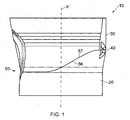
- the closure 10, as shown in Figure 1 comprises a base 20 and a lid 30 articulated to one another by a hinge 40.
- the lid 30 and base 20 meet at The closure 10, as shown in Figure 1 , comprises a base 20 and a lid 30 articulated to one another by a hinge 40.
- the lid 30 and base 20 meet at a parting line 55 which is defined by a parting surface 56 at the upper axial end of the base 20 and by a parting surface 57 at the lower axial end of the lid 30.
- the parting line 55 includes an inclined section 55a, extending from the hinge towards the open end of the base, and a linear section 55b which continues from the section 55a around to the tab 60 and recess 70.
- the parting surfaces 56, 57 are formed such that their size and shape allows the lid and base to contact one another at all points around the perimeter of the external wall of the closure 10 such that the external surface of the closure 10 has a contiguous surface.
- the base 20 and lid 30 are substantially cylindrical having a closure axis "A".
- This axis "A” passes through the centre of the cylindrical base 20 and lid 30.
- the axis "A” also passes through the centre of the mouth of the container.
- This closure axis "A” may also be described as a "dispensing axis”.
- the anti-rotation means 50 are provided substantially diametrically opposite, with respect to the closure axis "A", to the hinge 40.
- the lid 30 and base 20 may rotate relative to one another. This relative rotation may be about the closure axis "A” or another axis such as one lying substantially parallel to the closure axis "A” but passing through the hinge 40.
- lid 30 and base 20 have been described as substantially cylindrical it may be seen from the drawings that in this specific embodiment the lid 30 has an inverted frusto-conical shape such that the wider end is at the top of the closure and the narrower end is below the wider end when the closure is in the closed position.
- top relate to the closure as shown in Figure 1 in that the base part 20 is beneath the lid part 30.
- these terms relate to how a closure would typically be fitted to a container, such as a bottle, with this container standing upright with the closure at the top and the closure axis "A" being substantially vertical.
- Figure 2 more clearly shows the inverted frusto-conical shape of the lid 30 and the substantially cylindrical shape of the base 20 with the anti-rotation means 50 being visible on the side of the closure 10 at approximately the point where the lid 30 and base 20 meet.
- the lid 30 includes a stepped portion 35 which extends around its circumference. This may aid opening of the lid 30 in that it provides a gripping point for users.
- the anti-rotation means comprise a projection 60 provided on the lid 30 and a recess 70 provided on the base 20.
- the location of the projection and recess may be reversed in that the projection 60 lies on the base 20 and the recess 70 lies on the lid 30.
- the projection 60 comprises a substantially triangular shape having a rounded apex, with its base lying on and forming part of the parting surface 57 which forms part of the skirt surrounding the lid 30. It has a radial thickness substantially equal to the thickness of the upstanding rim, or skirt, which forms the outer wall of the lid 30.
- the recess, or socket, 70 has a similar size and shape to the projection 60 such that, with the closure in the closed position, the projection 60 may be received within the recess 70 such that there is minimal space therebetween.
- the projection 60 is provided on the perimeter of the parting surface 57 of the lid 30.
- the recess 70 is provided within the parting surface 56 on the perimeter, or skirt, of the base 20.
- the projection 60 and recess 70 are provided substantially diametrically opposite, relative to the closure axis "A", to the hinge 40.
- the hinge 40 is shown as an integrally moulded snap-type, or "butterfly" hinge.
- other forms of hinge such as simple straps, are also possible.
- the base 20 includes an orifice 80 provided within a raised top deck having a shoulder 100 and lying within the perimeter.
- the lid 30 includes a recessed surface 110 provided within the perimeter and which meets with the shoulder 100 when the closure is closed. When the lid is in the closed position the interaction between the shoulder 100 and the surface 110 may provide a sealing effect. However, this is not always necessary since other forms of sealing the closure may be provided. For instance, a sealing effect may be provided by the interaction of the parting surfaces 56, 57. Alternatively, or additionally, a spigot or bore seal (not shown) may be present on the underside of the lid 30 which seals against and/or within the orifice 80.
- Screw threads 90 are provided on the inside wall or skirt of the base 20. These threads 90 engage with corresponding threads on an associated container (not shown) for retaining the closure 10 to the container.
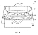
- Figure 4 shows an alternative view of the closure 10 in the open position in which the base 20, lid 30, hinge 40, parting surfaces 56, 57 and anti-rotation means 60, 70 are visible.
- the base 20 is visible in the foreground and the lid 30 is visible behind the base 20 in the background.
- each surface 56,57 lies in more than one plane. In other words, they do not lie entirely in a uniform plane.
- a portion 56B, 57B of each parting surface 56, 57 lies at a non-orthogonal angle to the closure axis "A" and a portion 56A, 57A.
- the interaction of the portions 56B, 57B of each of the parting surfaces 56, 57 prevent rotation of the base 20 with respect to the lid 30 about the closure axis "A" with the lid 30 in the closed position.
- parting surfaces 56, 57 are shown such that their surfaces do not lie in the same plane along their entire length in one embodiment they do lie in the same plane.
- This plane lies at a non-orthogonal angle with respect to the closure axis "A" so as to provide the same anti-rotation means in that relative rotation may only occur if the lid and base move apart axially.
- the projection 60 and recess 70 are shown on the perimeter of the lid 30 and base 20 respectively, they could lie within the perimeter of the closure 10. Such a design is improved if the anti-rotation features (50,60,70) are located substantially away from the hinge 40.
- the closure 110 comprises a base 120 and a lid 130 joined by a hinge 140.
- the base has a recess 170 and the lid has a correspondingly shaped tab 160.
- the recess and tab help to prevent relative rotation between the base and the lid.
- the parting line between the base and the lid is rectilinear, except for the region of the recess and tab.
- FIG. 8 there is shown a closure 210 formed according to an alternative embodiment.
- the closure 210 is very similar to the closure 110 of Figures 6 and 7 except that the parting plane 255 is inclined from the hinge towards the free end of the base 220.
Abstract
Description
- The present invention relates generally to a flip-top dispensing closure for a container and particularly to one including anti-rotation means.
- Flip-top dispensing closures typically comprise a base having a dispensing orifice, a lid, and hinge means for articulating the lid and base with respect to one another. The hinge means may be relatively delicate in that it is formed from relatively small pieces of material. For example, the closure including the hinge means may be moulded from plastics and the hinge means may be provided by at least one relatively thin strap.
- Flip-top dispensing closures are typically connected to an associated container in one of two ways. The first way is for the closure to be snap-fitted to the mouth of the associated container by the use of such means as snap-beads. The second way is for the closure to be screwed onto the associated container by means of corresponding screw threads, one set provided on the closure and the other set provided on the neck of the container. Regardless of which method is used to retain the closure onto the associated container, if the lid or base is grasped by a user, or by machinery during production, and twisted relative to the other of the lid and base and/or the associated container (if present), relative rotation between the lid and base may occur. This can lead to damage, and in some cases total destruction, of the hinge. This is undesirable for obvious reasons, for example the lid would not be retained to the base of the closure if the hinge was entirely broken.
- Such relative rotation between the lid and base may occur during capping of the associated container at the manufacturing facility. This may especially occur if the closures are screw-fitted to the containers.
- Although not designed with this purpose it is known that having flip-top dispensing closures with an orifice and an associated sealing spigot in which the orifice is offset from the closure axis (defined below), about which the relative rotation between the lid and base may occur, can help prevent the relative rotation. However, if a torque beyond a threshold value is applied to the lid and/or base then the spigot may break away from the lid and permanently block the orifice in the base. Accordingly, to rely on an offset spigot and associated dispensing orifice to provide anti-rotation means is not always effective and can in fact be detrimental.
- The present invention seeks to address the above described problems.
- According to a first aspect of the present invention, there is provided a flip-top dispensing closure comprising a base having a dispensing orifice, a lid, and hinge means for articulating the lid and base with respect to one another, the closure further including anti-rotation means for substantially preventing relative rotation between the lid and base.
- The anti-rotation means may be independent from the dispensing orifice and/or the hinge means. In this sense, the term "independent" means separate from, and/or having a different purpose from, and/or located away from the dispensing orifice and/or the hinge means.
- The anti-rotation means may be provided by a projection on one of the lid and base and a corresponding recess, for receiving the projection, on the other of the lid and base.
- The projection and recess may be provided substantially on the perimeter of the lid and base. However, the projection and corresponding recess may be provided radially inward from the perimeter of the lid and base. More than one set of corresponding projections and recesses may be provided.
- In one embodiment, the anti-rotation means may be provided by having a parting plane between the lid and base which lies at a non-orthogonal angle to the closure axis. Alternatively, or additionally, the anti-rotation means may be provided by a parting surface between the lid and base of which part lies at a non-orthogonal angle to the closure axis. These anti-rotation means may be present in addition, or as an alternative, to the projection and associated recess described herein.
- The size and shape of the lid and base along the perimeter of the closure at the parting surface may be substantially similar such that the external surface of the closure is contiguous.
- The dispensing orifice may take the form of a hole in the base through which the contents of the associated container may be dispensed. The hole may have a variety of sizes and shapes and is not limited to being centralised (with respect to the closure axis) and circular. The dispensing orifice may have an associated spout which may be formed integrally, or be separately assembled, with the closure. In one embodiment, the lid may include sealing means for sealing the dispensing orifice in the base when the closure is in the closed position. This sealing means may take the form of a spigot or bore seal.
- The lid and base may be integral with one another in that they are unitary, being connected by an integral hinge. However, the lid and base may be separate with a separate hinge or a hinge integral with either one of the base and lid.
- The anti-rotation features described herein may be separate from tamper evident features included in the closure. This has the benefit that the anti-rotation features still operate despite the possibility of the breakage of the tamper evident features upon first opening of the closure. However, it may be possible to incorporate tamper evident features with the anti-rotation features if desired.
- The closure may be moulded from a plastic material such as polypropylene or polyethylene.
- The parting line between the base and the lid may be substantially rectilinear. Alternatively the parting line may be non-rectilinear. In some embodiments the line is at least partly curved and in others it is inclined. A line including rectilinear and non-rectilinear sections is, of course, possible.
- At least part of the parting line may run generally perpendicular to the main axis of the closure. Alternatively or additionally at least part of the line may be inclined to a plane running perpendicular to the main axis of the closure backs.
- The present invention will now be more particularly described, by way of example, with reference to the accompanying drawings in which:
-
Figure 1 is an elevational side view of a closure, formed according to the present invention, in an unopened state; -
Figure 2 is an elevational front view of the closure ofFigure 1 ; -
Figure 3 is a perspective view of the closure ofFigure 1 in an opened state; -
Figure 4 is an elevational front view of the closure ofFigure 3 ; -
Figure 5 is an elevational side view of the closure ofFigure 3 ; -
Figure 6 is a side elevation of a closure formed according to an alternative embodiment; -
Figure 7 is a front view of the closure ofFigure 6 ; and -
Figure 8 is a side elevation of a closure formed according to an alternative embodiment. - The
closure 10, as shown inFigure 1 , comprises abase 20 and alid 30 articulated to one another by ahinge 40. In the closed position, thelid 30 andbase 20 meet at Theclosure 10, as shown inFigure 1 , comprises abase 20 and alid 30 articulated to one another by ahinge 40. In the closed position, thelid 30 andbase 20 meet at a parting line 55 which is defined by aparting surface 56 at the upper axial end of thebase 20 and by aparting surface 57 at the lower axial end of thelid 30. The parting line 55 includes an inclined section 55a, extending from the hinge towards the open end of the base, and a linear section 55b which continues from the section 55a around to thetab 60 and recess 70. Theparting surfaces closure 10 such that the external surface of theclosure 10 has a contiguous surface. - The
base 20 andlid 30 are substantially cylindrical having a closure axis "A". This axis "A" passes through the centre of thecylindrical base 20 andlid 30. In use, with the closure connected to an associated container, the axis "A" also passes through the centre of the mouth of the container. This closure axis "A" may also be described as a "dispensing axis". - The anti-rotation means 50 are provided substantially diametrically opposite, with respect to the closure axis "A", to the
hinge 40. - Without the anti-rotation means the
lid 30 andbase 20 may rotate relative to one another. This relative rotation may be about the closure axis "A" or another axis such as one lying substantially parallel to the closure axis "A" but passing through thehinge 40. - Although the
lid 30 andbase 20 have been described as substantially cylindrical it may be seen from the drawings that in this specific embodiment thelid 30 has an inverted frusto-conical shape such that the wider end is at the top of the closure and the narrower end is below the wider end when the closure is in the closed position. - Although within this description the words "top", "below", and other such relative terms are used, it should be understood that they relate to the closure as shown in
Figure 1 in that thebase part 20 is beneath thelid part 30. In other words, these terms relate to how a closure would typically be fitted to a container, such as a bottle, with this container standing upright with the closure at the top and the closure axis "A" being substantially vertical. These relative terms should not be regarded as limiting in any way to the scope of the invention. -
Figure 2 more clearly shows the inverted frusto-conical shape of thelid 30 and the substantially cylindrical shape of the base 20 with the anti-rotation means 50 being visible on the side of theclosure 10 at approximately the point where thelid 30 andbase 20 meet. - The
lid 30 includes a steppedportion 35 which extends around its circumference. This may aid opening of thelid 30 in that it provides a gripping point for users. - In
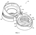
Figure 3 , in which only a partial view of thebase 20 is visible, the anti-rotation means are more clearly shown. The anti-rotation means comprise aprojection 60 provided on thelid 30 and arecess 70 provided on thebase 20. The location of the projection and recess may be reversed in that theprojection 60 lies on thebase 20 and therecess 70 lies on thelid 30. - In this embodiment the
projection 60 comprises a substantially triangular shape having a rounded apex, with its base lying on and forming part of theparting surface 57 which forms part of the skirt surrounding thelid 30. It has a radial thickness substantially equal to the thickness of the upstanding rim, or skirt, which forms the outer wall of thelid 30. The recess, or socket, 70 has a similar size and shape to theprojection 60 such that, with the closure in the closed position, theprojection 60 may be received within therecess 70 such that there is minimal space therebetween. Theprojection 60 is provided on the perimeter of theparting surface 57 of thelid 30. Likewise, therecess 70 is provided within theparting surface 56 on the perimeter, or skirt, of thebase 20. Theprojection 60 andrecess 70 are provided substantially diametrically opposite, relative to the closure axis "A", to thehinge 40. - Due to the interlocking of the
projection 60 andrecess 70, when the closure is in the closed position, relative rotation between thelid 30 andbase 20 is substantially prevented or inhibited. This effect may be enhanced by the presence of thehinge 40 in that thelid 30 andbase 20 are interlocked together at two points on substantially opposite sides of the closure axis "A". - In
Figure 3 , thehinge 40 is shown as an integrally moulded snap-type, or "butterfly" hinge. However, other forms of hinge, such as simple straps, are also possible. - The
base 20 includes anorifice 80 provided within a raised top deck having ashoulder 100 and lying within the perimeter. Thelid 30 includes a recessedsurface 110 provided within the perimeter and which meets with theshoulder 100 when the closure is closed. When the lid is in the closed position the interaction between theshoulder 100 and thesurface 110 may provide a sealing effect. However, this is not always necessary since other forms of sealing the closure may be provided. For instance, a sealing effect may be provided by the interaction of the parting surfaces 56, 57. Alternatively, or additionally, a spigot or bore seal (not shown) may be present on the underside of thelid 30 which seals against and/or within theorifice 80. -
Screw threads 90 are provided on the inside wall or skirt of thebase 20. Thesethreads 90 engage with corresponding threads on an associated container (not shown) for retaining theclosure 10 to the container. -
Figure 4 shows an alternative view of theclosure 10 in the open position in which thebase 20,lid 30,hinge 40, parting surfaces 56, 57 and anti-rotation means 60, 70 are visible. Thebase 20 is visible in the foreground and thelid 30 is visible behind the base 20 in the background. - In
Figure 5 , the shape of the parting surfaces 56, 57 is more clearly visible. Eachsurface portion surface portion portions lid 30 about the closure axis "A" with thelid 30 in the closed position. This is because for relative rotation to occur the parting surfaces 56, 57 would have to slide over one another about the axis "A" and the only way this could occur would be for thelid 30 andbase 20 to move apart axially. This axial separation may be prevented by the force of a snap-type hinge holding the base and lid in the closed position. - Although the parting surfaces 56, 57 are shown such that their surfaces do not lie in the same plane along their entire length in one embodiment they do lie in the same plane. This plane lies at a non-orthogonal angle with respect to the closure axis "A" so as to provide the same anti-rotation means in that relative rotation may only occur if the lid and base move apart axially.
- Although the
projection 60 andrecess 70 are shown on the perimeter of thelid 30 andbase 20 respectively, they could lie within the perimeter of theclosure 10. Such a design is improved if the anti-rotation features (50,60,70) are located substantially away from thehinge 40. - Referring now to
Figures 6 and 7 there is shown aclosure 110 formed according to an alternative embodiment. Theclosure 110 comprises abase 120 and alid 130 joined by ahinge 140. - Opposite the
hinge 140 the base has arecess 170 and the lid has a correspondingly shapedtab 160. In the closed position shown the recess and tab help to prevent relative rotation between the base and the lid. In this embodiment the parting line between the base and the lid is rectilinear, except for the region of the recess and tab. - Referring now to
Figure 8 there is shown aclosure 210 formed according to an alternative embodiment. Theclosure 210 is very similar to theclosure 110 ofFigures 6 and 7 except that theparting plane 255 is inclined from the hinge towards the free end of thebase 220.
Claims (14)
- A flip-top dispensing closure comprising a base having a dispensing orifice, a lid, and hinge means for articulating the lid and base with respect to one another, the closure further including anti-rotation means for substantially preventing relative rotation between the lid and base.
- A closure according to Claim 1, wherein the anti-rotation means are independent from the hinge means and/or the dispensing orifice.
- A closure according to either of claims 1 and 2, wherein the anti-rotation means are provided by a projection on one of the lid and base and a recess, for receiving the projection, on the other of the lid and base.
- A closure according to Claim 3, wherein the projection and recess are provided substantially on the perimeter of the lid and base.
- A closure according to Claim 3, wherein the projection and recess are provided radially inward from the perimeter of the lid and base.
- A closure according to any preceding claim, wherein the anti-rotation means are provided by a parting surface between the lid and base part of which lies at a non-orthogonal angle to the closure axis.
- A closure according to any preceding claim, wherein the size and shape of the lid and base along the perimeter of the closure at the parting surface are substantially similar such that the external surface of the closure is contiguous.
- A closure according to any preceding claim, wherein the lid includes sealing means for sealing a dispensing orifice in the base when the closure is in the closed position.
- A closure according to Claim 8, wherein the sealing means is a spigot.
- A closure according to any preceding claim, in which the parting line between the base and the lid is substantially rectilinear.
- A closure according to any of Claims 1 to 9, in which the parting line between the base and the lid is non-rectilinear.
- A closure according to Claim 11, in which the parting line between the base and the lid is at least partly curved.
- A closure according to at least part of any preceding claim in which the parting line is generally perpendicular to the main axis of the closure body.
- A closure according to any of Claims 1 to 12, in which at least part of the parting line is inclined to a plane running perpendicular to the main axis of the closure body.
Applications Claiming Priority (1)
| Application Number | Priority Date | Filing Date | Title |
|---|---|---|---|
| GB0718913A GB0718913D0 (en) | 2007-09-28 | 2007-09-28 | Flip-top dispensing closure |
Publications (1)
| Publication Number | Publication Date |
|---|---|
| EP2045192A1 true EP2045192A1 (en) | 2009-04-08 |
Family
ID=38701798
Family Applications (1)
| Application Number | Title | Priority Date | Filing Date |
|---|---|---|---|
| EP08252743A Withdrawn EP2045192A1 (en) | 2007-09-28 | 2008-08-19 | Flip-top dispensing closure |
Country Status (2)
| Country | Link |
|---|---|
| EP (1) | EP2045192A1 (en) |
| GB (2) | GB0718913D0 (en) |
Cited By (2)
| Publication number | Priority date | Publication date | Assignee | Title |
|---|---|---|---|---|
| US8444019B2 (en) | 2009-08-07 | 2013-05-21 | Ecolab Usa Inc. | Wipe and seal product pump |
| US11697535B2 (en) | 2020-12-11 | 2023-07-11 | Sacmi Cooperativa Meccanici Imola Societa' Cooperativa | Cap for a container |
Citations (4)
| Publication number | Priority date | Publication date | Assignee | Title |
|---|---|---|---|---|
| US4717033A (en) * | 1985-08-19 | 1988-01-05 | Alfatechnic Ag | Plastic closure with safety band |
| DE20009203U1 (en) * | 1999-12-23 | 2001-06-07 | Seaquist Loeffler Kunststoffwerk Gmbh | Hinged lid lock with tamper-evident device |
| EP1174359A2 (en) * | 2000-07-13 | 2002-01-23 | Alpla Werke Alwin Lehner GmbH & CO. KG | Closure for a container |
| EP1382539A1 (en) * | 2002-07-17 | 2004-01-21 | L&M SERVICES B.V. | Two-stage injection moulded closure |
Family Cites Families (17)
| Publication number | Priority date | Publication date | Assignee | Title |
|---|---|---|---|---|
| GB833270A (en) * | 1957-10-17 | 1960-04-21 | British Xylonite Co Ltd | Improvements relating to plugs for containers |
| US3227332A (en) * | 1963-09-27 | 1966-01-04 | Procter & Gamble | Captive closure |
| FR2044010A5 (en) * | 1969-05-06 | 1971-02-19 | Courreges Parfums | |
| FR2600631B1 (en) * | 1986-06-26 | 1989-03-31 | Rical Sa | TAMPER ASSEMBLY AND CAPPING CAP |
| CH678843A5 (en) * | 1989-06-09 | 1991-11-15 | Alfatechnic Ag | |
| US5356017A (en) * | 1992-10-28 | 1994-10-18 | Aptargroup, Inc. | Child resistant closure with recessed latch |
| US5979706A (en) * | 1994-02-10 | 1999-11-09 | Grussmark; Stephen M. | Combination dental floss dispenser and stand-up toothpaste container |
| US5462185A (en) * | 1994-07-18 | 1995-10-31 | Walker, Iii; Clifford M. | Dispensing closure for fluid containers |
| JPH08282690A (en) * | 1995-04-18 | 1996-10-29 | Toppan Printing Co Ltd | Tubular inverted container |
| AU5638298A (en) * | 1997-09-09 | 1999-03-25 | Johnson & Johnson Consumer Companies, Inc. | Dispensing container |
| US5971232A (en) * | 1998-06-03 | 1999-10-26 | Aptargroup, Inc. | Dispensing structure which has a pressure-openable valve retained with folding elements |
| DE10207204A1 (en) * | 2001-04-05 | 2002-12-12 | Alpla Werke | Combination of a bottle with a snap-on adapter and / or a cap |
| GB2401859A (en) * | 2003-04-17 | 2004-11-24 | Portola Packaging Ltd | Closure with integral spaced hinge portions |
| US7404495B2 (en) * | 2003-07-28 | 2008-07-29 | Rexam Closure Systems Inc. | Child-resistant flip-top dispensing closure and package |
| US20060016836A1 (en) * | 2004-07-20 | 2006-01-26 | Rick Gaiser | Shaped spouts for flip-top closures |
| GB2422372A (en) * | 2005-01-29 | 2006-07-26 | Garry Ritchie | Gravity dispenser for fluid |
| GB2454926B (en) * | 2007-11-26 | 2012-08-01 | Obrist Closures Switzerland | Closure with latch |
-
2007
- 2007-09-28 GB GB0718913A patent/GB0718913D0/en not_active Ceased
-
2008
- 2008-08-19 EP EP08252743A patent/EP2045192A1/en not_active Withdrawn
- 2008-08-19 GB GB0815215A patent/GB2453205B/en not_active Expired - Fee Related
Patent Citations (4)
| Publication number | Priority date | Publication date | Assignee | Title |
|---|---|---|---|---|
| US4717033A (en) * | 1985-08-19 | 1988-01-05 | Alfatechnic Ag | Plastic closure with safety band |
| DE20009203U1 (en) * | 1999-12-23 | 2001-06-07 | Seaquist Loeffler Kunststoffwerk Gmbh | Hinged lid lock with tamper-evident device |
| EP1174359A2 (en) * | 2000-07-13 | 2002-01-23 | Alpla Werke Alwin Lehner GmbH & CO. KG | Closure for a container |
| EP1382539A1 (en) * | 2002-07-17 | 2004-01-21 | L&M SERVICES B.V. | Two-stage injection moulded closure |
Cited By (2)
| Publication number | Priority date | Publication date | Assignee | Title |
|---|---|---|---|---|
| US8444019B2 (en) | 2009-08-07 | 2013-05-21 | Ecolab Usa Inc. | Wipe and seal product pump |
| US11697535B2 (en) | 2020-12-11 | 2023-07-11 | Sacmi Cooperativa Meccanici Imola Societa' Cooperativa | Cap for a container |
Also Published As
| Publication number | Publication date |
|---|---|
| GB2453205A (en) | 2009-04-01 |
| GB0718913D0 (en) | 2007-11-07 |
| GB0815215D0 (en) | 2008-09-24 |
| GB2453205B (en) | 2010-11-03 |
Similar Documents
| Publication | Publication Date | Title |
|---|---|---|
| CA3112075C (en) | Twist and flip lock closure | |
| EP3305680B1 (en) | Stopper for containers | |
| EP2580138B1 (en) | Tamper evident closure | |
| US7644843B1 (en) | Reverse taper dispensing orifice seal | |
| EP2750987B1 (en) | Tamper-evident closure | |
| US20160244219A1 (en) | A method of manufacturing a tamper-evident closure | |
| US9409680B2 (en) | Tamper evident closure | |
| EP1876110A1 (en) | Drinking spout and closure combination for a beverage container | |
| US20130119062A1 (en) | Closure | |
| US7635071B1 (en) | Double shell dispensing closure with a reverse tapered drop lug | |
| CN109153479B (en) | Container lid comprising a tamper-evident device | |
| JP2011111193A (en) | Container cap made of synthetic resin | |
| JP6243354B2 (en) | Refill container pouring structure | |
| GB2512620A (en) | Tamper Evident Child Resistant Flip-Top Closure | |
| EP3102501B1 (en) | Container closure | |
| GB2454926A (en) | A flip-top dispensing closure with latch | |
| EP2045192A1 (en) | Flip-top dispensing closure | |
| JP4965647B2 (en) | A lid with a sealed container mouth and a cover cap for initial opening | |
| US20210284404A1 (en) | A cap for a food package | |
| US11613412B2 (en) | Tethered plastic stopper | |
| JP5590913B2 (en) | Plastic container lid | |
| EP3409612A1 (en) | A spout for a food package | |
| WO2005058722A2 (en) | Container closure | |
| JP6992383B2 (en) | cap | |
| WO2015181978A1 (en) | Container opening |
Legal Events
| Date | Code | Title | Description |
|---|---|---|---|
| PUAI | Public reference made under article 153(3) epc to a published international application that has entered the european phase |
Free format text: ORIGINAL CODE: 0009012 |
|
| STAA | Information on the status of an ep patent application or granted ep patent |
Free format text: STATUS: THE APPLICATION HAS BEEN PUBLISHED |
|
| AK | Designated contracting states |
Kind code of ref document: A1 Designated state(s): AT BE BG CH CY CZ DE DK EE ES FI FR GB GR HR HU IE IS IT LI LT LU LV MC MT NL NO PL PT RO SE SI SK TR |
|
| AX | Request for extension of the european patent |
Extension state: AL BA MK RS |
|
| AKX | Designation fees paid | ||
| REG | Reference to a national code |
Ref country code: DE Ref legal event code: 8566 |
|
| STAA | Information on the status of an ep patent application or granted ep patent |
Free format text: STATUS: THE APPLICATION IS DEEMED TO BE WITHDRAWN |
|
| 18D | Application deemed to be withdrawn |
Effective date: 20091009 |