EP2050685A1 - Convertible child-resistant vial - Google Patents
Convertible child-resistant vial Download PDFInfo
- Publication number
- EP2050685A1 EP2050685A1 EP08158257A EP08158257A EP2050685A1 EP 2050685 A1 EP2050685 A1 EP 2050685A1 EP 08158257 A EP08158257 A EP 08158257A EP 08158257 A EP08158257 A EP 08158257A EP 2050685 A1 EP2050685 A1 EP 2050685A1
- Authority
- EP
- European Patent Office
- Prior art keywords
- vial
- cap
- container
- tooth
- child
- Prior art date
- Legal status (The legal status is an assumption and is not a legal conclusion. Google has not performed a legal analysis and makes no representation as to the accuracy of the status listed.)
- Granted
Links
Images

Classifications
-
- B—PERFORMING OPERATIONS; TRANSPORTING
- B65—CONVEYING; PACKING; STORING; HANDLING THIN OR FILAMENTARY MATERIAL
- B65D—CONTAINERS FOR STORAGE OR TRANSPORT OF ARTICLES OR MATERIALS, e.g. BAGS, BARRELS, BOTTLES, BOXES, CANS, CARTONS, CRATES, DRUMS, JARS, TANKS, HOPPERS, FORWARDING CONTAINERS; ACCESSORIES, CLOSURES, OR FITTINGS THEREFOR; PACKAGING ELEMENTS; PACKAGES
- B65D50/00—Closures with means for discouraging unauthorised opening or removal thereof, with or without indicating means, e.g. child-proof closures
- B65D50/02—Closures with means for discouraging unauthorised opening or removal thereof, with or without indicating means, e.g. child-proof closures openable or removable by the combination of plural actions
- B65D50/06—Closures with means for discouraging unauthorised opening or removal thereof, with or without indicating means, e.g. child-proof closures openable or removable by the combination of plural actions requiring the combination of different actions in succession
- B65D50/061—Closures with means for discouraging unauthorised opening or removal thereof, with or without indicating means, e.g. child-proof closures openable or removable by the combination of plural actions requiring the combination of different actions in succession being disengageable from container only after rotational alignment of closure, or other means inhibiting removal of closure, with container, e.g. tortuous path type
- B65D50/062—Closures with means for discouraging unauthorised opening or removal thereof, with or without indicating means, e.g. child-proof closures openable or removable by the combination of plural actions requiring the combination of different actions in succession being disengageable from container only after rotational alignment of closure, or other means inhibiting removal of closure, with container, e.g. tortuous path type the closure removal inhibiting means being a displaceable ring
-
- A—HUMAN NECESSITIES
- A61—MEDICAL OR VETERINARY SCIENCE; HYGIENE
- A61J—CONTAINERS SPECIALLY ADAPTED FOR MEDICAL OR PHARMACEUTICAL PURPOSES; DEVICES OR METHODS SPECIALLY ADAPTED FOR BRINGING PHARMACEUTICAL PRODUCTS INTO PARTICULAR PHYSICAL OR ADMINISTERING FORMS; DEVICES FOR ADMINISTERING FOOD OR MEDICINES ORALLY; BABY COMFORTERS; DEVICES FOR RECEIVING SPITTLE
- A61J1/00—Containers specially adapted for medical or pharmaceutical purposes
- A61J1/03—Containers specially adapted for medical or pharmaceutical purposes for pills or tablets
-
- B—PERFORMING OPERATIONS; TRANSPORTING
- B65—CONVEYING; PACKING; STORING; HANDLING THIN OR FILAMENTARY MATERIAL
- B65D—CONTAINERS FOR STORAGE OR TRANSPORT OF ARTICLES OR MATERIALS, e.g. BAGS, BARRELS, BOTTLES, BOXES, CANS, CARTONS, CRATES, DRUMS, JARS, TANKS, HOPPERS, FORWARDING CONTAINERS; ACCESSORIES, CLOSURES, OR FITTINGS THEREFOR; PACKAGING ELEMENTS; PACKAGES
- B65D43/00—Lids or covers for rigid or semi-rigid containers
- B65D43/14—Non-removable lids or covers
- B65D43/16—Non-removable lids or covers hinged for upward or downward movement
- B65D43/162—Non-removable lids or covers hinged for upward or downward movement the container, the lid and the hinge being made of one piece
-
- B—PERFORMING OPERATIONS; TRANSPORTING
- B65—CONVEYING; PACKING; STORING; HANDLING THIN OR FILAMENTARY MATERIAL
- B65D—CONTAINERS FOR STORAGE OR TRANSPORT OF ARTICLES OR MATERIALS, e.g. BAGS, BARRELS, BOTTLES, BOXES, CANS, CARTONS, CRATES, DRUMS, JARS, TANKS, HOPPERS, FORWARDING CONTAINERS; ACCESSORIES, CLOSURES, OR FITTINGS THEREFOR; PACKAGING ELEMENTS; PACKAGES
- B65D50/00—Closures with means for discouraging unauthorised opening or removal thereof, with or without indicating means, e.g. child-proof closures
- B65D50/02—Closures with means for discouraging unauthorised opening or removal thereof, with or without indicating means, e.g. child-proof closures openable or removable by the combination of plural actions
- B65D50/04—Closures with means for discouraging unauthorised opening or removal thereof, with or without indicating means, e.g. child-proof closures openable or removable by the combination of plural actions requiring the combination of simultaneous actions, e.g. depressing and turning, lifting and turning, maintaining a part and turning another one
- B65D50/045—Closures with means for discouraging unauthorised opening or removal thereof, with or without indicating means, e.g. child-proof closures openable or removable by the combination of plural actions requiring the combination of simultaneous actions, e.g. depressing and turning, lifting and turning, maintaining a part and turning another one where one action elastically deforms or deflects at least part of the closure, the container or an intermediate element, e.g. a ring
-
- B—PERFORMING OPERATIONS; TRANSPORTING
- B65—CONVEYING; PACKING; STORING; HANDLING THIN OR FILAMENTARY MATERIAL
- B65D—CONTAINERS FOR STORAGE OR TRANSPORT OF ARTICLES OR MATERIALS, e.g. BAGS, BARRELS, BOTTLES, BOXES, CANS, CARTONS, CRATES, DRUMS, JARS, TANKS, HOPPERS, FORWARDING CONTAINERS; ACCESSORIES, CLOSURES, OR FITTINGS THEREFOR; PACKAGING ELEMENTS; PACKAGES
- B65D2251/00—Details relating to container closures
- B65D2251/10—Details of hinged closures
- B65D2251/1016—Means for locking the closure in closed position
- B65D2251/1025—Integral locking elements penetrating in an opening, e.g. a flap through a slit, a hook in an opening
Definitions
- the present invention generally relates to child-resistant safety vials. More specifically, the present invention relates to a child-resistant vial which may be converted to a non-child-resistant vial by the individual dispensing the vial to the user. The use of such child-resistant vials is common to contain and distribute medications.
- Child-resistant vials have been known for some times. They come in many flavours. According to one type of child-resistant containers, the interior of the cap is provided with a liner that exerts a pressure onto the container for preventing the vial from being open easily, for example by children. A drawback of this first type of vials is that they require a first mold for the container and a second mold for the cap. Their assembly is also a two-step process including the assembly of the liner in the cap and then the assembly of the cap onto the vial.
- This type of child-resistant vials is the arrow-type vial.
- This vial includes a container including a groove and a cap provided with a tooth; the cap being removable only when the tooth and groove are aligned. Arrows are provided on both the cap and the container to guide a user in aligning the tooth and groove.
- This type of vials still requires a two-step molding process.
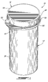
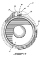
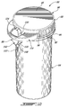
- Figure 1 is a top perspective view of a child-resistant vial according to a first illustrative embodiment of the present invention; the vial being illustrated closed and in a child-resistant configuration;
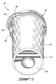
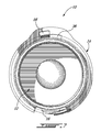
- Figure 2 is a top perspective view of the child-resistant vial from Figure 1 ; the vial being illustrated opened;
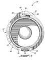
- Figure 3 is a bottom perspective view of the child-resistant vial from Figure 1 ,
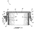
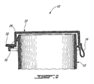
- Figure 4 is a partial cross section of the child-resistant vial from Figure 1 , illustrating the mounting of the cap on the container in a child-resistant configuration;
- Figures 5 to 7 are bottom plan views of the child-resistant vial from Figure 1 , illustrating the removal of the cap in the child-resistant configuration;
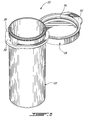
- Figure 8 is a top perspective view of the child-resistant vial from Figure 1 , showing the locking teeth of the cap removed so as to illustrate the non-child-resistant configuration;
- Figure 9 is a partial cross section similar to Figure 4 , illustrating the mounting of the cap on the container in a non-child-resistant configuration
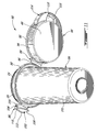
- Figure 10 is a top perspective view of a child-resistant vial according to a second illustrative embodiment of the present invention; the vial being illustrated closed and in a child-resistant configuration; and
- Figure 11 is a top perspective view of the child-resistant vial from Figure 10 ; the vial being illustrated opened.
- a convertible child-resistant vial comprising:
- a container having and aperture and a peripheral wall and being provided with a first connection element
- Child-resistant is well-known in the art. It should therefore not be limited herein in any ways.
- the expression child-resistant should be construed herein to include something or an operation that cannot be executed by a normal child or by any person having limited abilities with his/her hands, such as arthritics. This includes, without limitations, operations which can only successively be performed by combining at least two actions.
- the vial from the present invention is one piece and can be obtained through a conventional on-step molding process for example.
- the vial according to the present invention includes a cap that is integrally mounted to the container, which eases the distribution and handling of the vial as a single piece.
- the present vial is easily convertible from a child-resistant to a non-child-resistant configuration by removing the second connection element using, for example, a cutting tool or simply by jiggling it.
- a convertible child-resistant vial 10 according to a first illustrated embodiment of the present invention will now be described with reference to Figures 1 to 4 .
- the vial 10 comprises a container 12 and an integral cap 14, hingedly mounted to the container 12 via an integral hinge 16.
- the container 12, cap 14 and hinge 16 define a one piece body which is obtained through conventional molding process using a polymeric material such as copolymeric polypropylene. Other material, which can further be bio-degradable, can also be used, for example.
- the container 12 is in the form of a hollow cylindrical body, having a peripheral wall 18 and a bottom 20 and defining a cavity 22.
- the peripheral wall 18 has an upper edge 24 which is provided with a peripheral lip 26.
- the lip 26 includes an undercut 28 registered with the hinge 16 (see Figure 5 ), broader therefore, to ease pivoting the cap 14 as will be described furtherin.
- the container 12 further includes a collar 30 located below the peripheral lip 26.
- the collar 30 includes an enlarged portion, which defines a tab 32, and an undercut 34 located diametrically opposite the tab 32.
- the collar undercut 34 is registered with the lip undercut 28 and is similarly dimensioned. The collar undercut 34 is provided for similar reason than the lip undercut 28.
- the tab portion 32 of the collar 30 includes first and second contiguous notches 36 and 38 which respectively define first and second housings with the peripheral wall 18 for respectively locking and freeing a locking element 56 of the cap 14.
- the second notch 38 extends radially from the container wall 18 beyond the first notch 36.
- the side wall 40 of the second notch 38 which is adjacent the first notch 36, includes a small lip 42, the purpose of which will be described furtherin.
- the collar 30 is further provided with a flange 44.
- the cap 14 includes a top portion 46, dimensioned to conform to the circular contour of the wall 18, and a peripheral skirt 48 extending from the disk portion 46.
- the distal end of the skirt 48 is provided with a peripheral flange 50 having an enlarged portion defining a tab 52.
- the length of the skirt 48 with the flange 50 is such that the flange 50 contacts the flange 44 of the container 12.
- the skirt 48 is provided with two diametrically opposite corrugated portions 54 to increase the grip on the cap 14 during manipulation as will be described furthering in more detail.
- the tab 52 is positioned diametrically opposite the hinge 16.
- the cap 14 further includes a locking tooth 56 extending from the skirt 48 and registered with the first notch 36 of the container tab 32.
- the locking tooth 56 includes a generally arrow-shaped body 58 connected to the skirt 48 via a stem portion 60.
- the arrow-shaped body 58 includes a first longitudinal side 62, which is flush with the inner surface of the skirt 48, and an opposite slanted side 64, which extends from the distal end 66 of the tooth 56 to a shoulder portion 68 defined by the body 58 and the stem portion 60 at the intersection thereof.
- the body 58 is dimensioned for easy insertion of the tooth 56 in the locking housing 36 when the cap 14 is positioned on the container 12. However, the removal of the cap 14 by pulling thereonto is prevented by the abutment of the shoulder 68 of the tooth 56 onto the tab 32. The closure of the vial 10 is thereby child-resistant.
- the tooth 56 define a second connection element that cooperates with the first connection element defined by the two notches 36-38 to close the vial 10 in a child-resistant manner as will be described furtherin.
- the inner surface of the skirt 54 of the cap 14 includes a peripheral ring 70 to put pressure on the lip 26 of the edge of the container 12 so that the cap 14 is further secured to the container 12 in a snap-fit manner when it is positioned thereon.
- the integral hinge 16 is in the form of a generally planar element having one fold 72, a first end 74 connected to the container wall 18 and a second end 76 connected to the cap 14 and more specifically to its skirt 48.
- the hinge 16 may alternatively have other configuration and sizes.
- the integral cap 14 is rotated in a direction that moves the tooth 56 from the locking housing 36 to the freeing housing 38 (see arrow 78).
- a force sufficient force to overcome the resistance caused by the small lip 42 on the stem portion 60 of the tooth 56 must be provided during rotation of the cap 14.
- the user can begin exerting a pulling force on the cap 14, using for example the tab 32 (see arrow 80 on Figure 6 ), so as to be able to lift the cap 14 when the tooth 56 is completely housed in the second notch 38 as illustrated in Figure 7 .
- the integral hinge 16 is temporarily deformed by the rotation of the cap 14 during the opening of the vial 10, the cap 14 is biased in a neutral position, corresponding to the tooth 56 being aligned with the locking housing 36, when no rotational force is exerted onto the cap 14.
- This biasing force towards the neutral position is caused by the molecular memory of the polymer. It first results from this biasing force that a pivoting force sufficient to overcome both the resistance of the lip 42 on the tooth 56 and the biasing force is required in order to achieve the opening of the vial 10.
- a further consequence of the biasing force caused by the hinge 16 is that once the cap 14 is opened and released by the user, the cap 14 returns to its neutral position causing the tooth 56 to align with the locking housing 36.
- the vial 10 can then be closed by pivoting the cap 14 about the hinge 16 until the tooth 56 is positioned below the tab 32.
- the vial 10 can be permanently converted from a child-resistant configuration to non-child-resistant configuration by removing the tooth 56 (see Figures 8 and 9 ). This can be achieved by breaking the stem portion 62 of the tooth 56 using for example a cutting tool such as scissors (not shown) or simply by jiggling repeatedly the tooth 56 until it fells. This operation can be done for example by a professional such as a pharmacist before filling the vial 10 with drugs.
- the vial 10 is therefore adaptable for a specific user's need. For example, some users, such as elders, people with limited manual dexterity, or simply others which do not have the need for the child-resistant feature, may remove the tooth 56. It is reminded that the cap 14 is still attached to the container when the vial 10 is in the non-child-resistant configuration.
- the lip 26 is provided only on a small portion of the edge 24 with the skirt 48 of the cap 14 being provided with registered elements to prevent the cap from inadvertently opening.
- a convertible child-resistant vial 82 according to a second illustrative embodiment of the present invention will be described. Since the vial 82 is similar to the vial 10, and for concision purposes, only the differences between the vials 82 and 10 will be described, the main differences pertaining to the first and second connection means.
- the vial 82 comprises a container 84 and an integral cap 86, hingedly mounted to the container 84 via an integral hinge 88.
- the container 84 includes a collar 90 located below the peripheral lip 26.
- the integral hinge 88 extends from both the collar 90 and from a peripheral flange 92 of the cap 86, thereby further connecting the cap 86 to the container 84.
- the peripheral flange 92 extends from a skirt 94, which is similar to the skirt 48 of the vial 10.
- the hinge 88 includes a throat portion 96 to increase the flexibility of the hinge 98.
- a first connection element in the form of a locking tooth 98, is integrally mounted to the collar 90 diametrically opposite the hinge 88.
- the locking tooth 98 is generally in the form of an inverted U-shaped member having a generally flat stem portion 100 extending from the collar 90 upwardly and a generally flat locking portion 102 connected to the stem portion 100 and distanced therefrom by a bridge portion 104.
- the bridge portion 104 provides a gap between the stem and locking portions 100 and 102 and allows the locking portion 102 to be movable between a neutral locking position (see on Figures 10 and 11 ) to an unlocking position which corresponds to the locking portion 102 (not shown) being moved towards the stem portion 100 beyond a threshold position.
- the bridge portion 104 causes the locking portion 102 to be biased to its locking position when no force is exerted thereon.
- the locking portion 102 includes a tapered portion 106 having a rounded edge 108.
- the tapered portion 106 is connected to the bridge 104 through an abruptly thicker portion 110 which defines a shoulder 112 with the tapered portion 106.
- the cap 86 includes a top portion 46 and a peripheral skirt 48 extending from the top portion 46.
- the second connection element is in the form of a tab 114 extending from the skirt 94 opposite the hinge 88 and having a thickness.
- the tab 114 includes a notch 116 positioned diametrically opposite the hinge 88 so as to be registered with the locking tooth 98 when the vial 82 is closed by the cap 86.
- a shoulder 118 is provided in the notch 108 and defines a stop for the shoulder 112 of the locking tooth 98 when the tooth 98 is inserted in the notch 116.
- both the tapered portion 106 and the rounded edge 108 of the tooth 98 allow easing the insertion of the tooth 98 in the notch 116 when the cap 86 is pivoted onto the container 84 during the closing of the vial 82.
- the vial 82 can be opened by simultaneously pushing the tapered portion 106 of the tooth 98 towards the container 84 (see arrow 120 on Figure 10 ) while lifting the cap 86, for example by pushing upwardly onto the tooth 98 so as to pivot the cap 86 (see arrow 122 on Figure 10 ).
- the vial 82 In its child-proof configuration, the vial 82 requires two actions thereon for its opening.
- the vial 82 is illustrated with the tooth 98 being mounted to the container 84 and the notch 116 with the shoulder 118 being provided on the cap 86, it is believed to be within the reach of a person having ordinary skills in the art to use the present teaching to modify the vial 82 so that the tooth 98 is provided on the cap 86 and the notch 116 with the shoulder 118 is provided on the container 84, for example on a collar thereof (not shown).
- the vial 82 can be modified so that the unlocking of the cap 86 is achieved by another operation on the tooth 98 than its pushing onto the container 84.
- the tooth can be modified to allow the unlocking of the cap by simultaneously lifting the cap and pulling onto the tooth in a direction away from the container.
- a vial according to the present can be used to contain medicine, toxic matter or any other substance that has to be kept out of reach of children. Of course, it can be used to contain non-toxic matter also.
- the container can take other form than of a cylindrical body.
- the shape and configuration of the container and/or of its aperture can also be regular or irregular.
- an irregular shape container includes a cylindrical neck at its opening, which is configured to receive a round cap.
- connection elements of a vial are not limited to notches and a tooth.
- one of the connection elements can be in the form of a protrusion while the other is in the form of a complementary element for providing locking of the cap in a child-resistant way when the vial is closed.
- more than one pair of first and second connection elements can be provided for additional safety.
Landscapes
- Mechanical Engineering (AREA)
- Engineering & Computer Science (AREA)
- Health & Medical Sciences (AREA)
- Veterinary Medicine (AREA)
- General Health & Medical Sciences (AREA)
- Public Health (AREA)
- Animal Behavior & Ethology (AREA)
- Life Sciences & Earth Sciences (AREA)
- Pharmacology & Pharmacy (AREA)
- Medical Preparation Storing Or Oral Administration Devices (AREA)
- Closures For Containers (AREA)
- Materials For Medical Uses (AREA)
- Medicines Containing Material From Animals Or Micro-Organisms (AREA)
Abstract
Description
- The present invention generally relates to child-resistant safety vials. More specifically, the present invention relates to a child-resistant vial which may be converted to a non-child-resistant vial by the individual dispensing the vial to the user. The use of such child-resistant vials is common to contain and distribute medications.
- Many types of vials exist to provide prescription medication to users. The simplest model consists in a container and an independent cap so mounted to the container that it can be removed simply by pulling on the cap.
- Child-resistant vials have been known for some times. They come in many flavours. According to one type of child-resistant containers, the interior of the cap is provided with a liner that exerts a pressure onto the container for preventing the vial from being open easily, for example by children. A drawback of this first type of vials is that they require a first mold for the container and a second mold for the cap. Their assembly is also a two-step process including the assembly of the liner in the cap and then the assembly of the cap onto the vial.
- Another well-known type of child-resistant vials is the arrow-type vial. This vial includes a container including a groove and a cap provided with a tooth; the cap being removable only when the tooth and groove are aligned. Arrows are provided on both the cap and the container to guide a user in aligning the tooth and groove. This type of vials still requires a two-step molding process.
- Among the child-resistant vials, some have been proposed to convert the vial from a child-resistant configuration to a non-child-resistant configuration, for example by designing the neck of the container so that it can receive both arrow-type caps and caps that are not provided with a locking tooth.
- Other convertible child-resistant vials are known which are more complicated and include a cap detached from the container and therefore requiring a two-part molding process.
- In the appended drawings:
-
Figure 1 is a top perspective view of a child-resistant vial according to a first illustrative embodiment of the present invention; the vial being illustrated closed and in a child-resistant configuration; -
Figure 2 is a top perspective view of the child-resistant vial fromFigure 1 ; the vial being illustrated opened; -
Figure 3 is a bottom perspective view of the child-resistant vial fromFigure 1 , -
Figure 4 is a partial cross section of the child-resistant vial fromFigure 1 , illustrating the mounting of the cap on the container in a child-resistant configuration; -
Figures 5 to 7 are bottom plan views of the child-resistant vial fromFigure 1 , illustrating the removal of the cap in the child-resistant configuration; -
Figure 8 is a top perspective view of the child-resistant vial fromFigure 1 , showing the locking teeth of the cap removed so as to illustrate the non-child-resistant configuration; -
Figure 9 is a partial cross section similar toFigure 4 , illustrating the mounting of the cap on the container in a non-child-resistant configuration; -
Figure 10 is a top perspective view of a child-resistant vial according to a second illustrative embodiment of the present invention; the vial being illustrated closed and in a child-resistant configuration; and -
Figure 11 is a top perspective view of the child-resistant vial fromFigure 10 ; the vial being illustrated opened. - More specifically, in accordance with the present invention, there is provided a convertible child-resistant vial comprising:
- a container having and aperture and a peripheral wall and being provided with a first connection element; and
- a cap hingedly mounted to the container integrally thereof for closing the aperture and including a second connection element for cooperating with the first connection element of the container to close the vial in a child-resistant manner; one of the first and second connection elements being removable to convert the child-resistant vial into a non-child-resistant vial
- It is believed that the meaning of the expression "child-resistant" is well-known in the art. It should therefore not be limited herein in any ways. The expression child-resistant should be construed herein to include something or an operation that cannot be executed by a normal child or by any person having limited abilities with his/her hands, such as arthritics. This includes, without limitations, operations which can only successively be performed by combining at least two actions.
- The vial from the present invention is one piece and can be obtained through a conventional on-step molding process for example.
- Contrarily to vials from the prior art, the vial according to the present invention includes a cap that is integrally mounted to the container, which eases the distribution and handling of the vial as a single piece.
- The present vial is easily convertible from a child-resistant to a non-child-resistant configuration by removing the second connection element using, for example, a cutting tool or simply by jiggling it.
- Other objects, advantages and features of the present invention will become more apparent upon reading the following non restrictive description of illustrated embodiments thereof, given by way of example only with reference to the accompanying drawings.
- In the following description, similar features in the drawings have been given similar reference numerals, and in order not to weigh down the figures, some elements are not referred to in some figures if they were already identified in a precedent figure.
- A convertible child-
resistant vial 10 according to a first illustrated embodiment of the present invention will now be described with reference toFigures 1 to 4 . - The
vial 10 comprises acontainer 12 and anintegral cap 14, hingedly mounted to thecontainer 12 via anintegral hinge 16. Thecontainer 12,cap 14 andhinge 16 define a one piece body which is obtained through conventional molding process using a polymeric material such as copolymeric polypropylene. Other material, which can further be bio-degradable, can also be used, for example. - The
container 12 is in the form of a hollow cylindrical body, having aperipheral wall 18 and abottom 20 and defining acavity 22. Theperipheral wall 18 has anupper edge 24 which is provided with aperipheral lip 26. Thelip 26 includes an undercut 28 registered with the hinge 16 (seeFigure 5 ), broader therefore, to ease pivoting thecap 14 as will be described furtherin. - The
container 12 further includes acollar 30 located below theperipheral lip 26. Thecollar 30 includes an enlarged portion, which defines atab 32, and anundercut 34 located diametrically opposite thetab 32. Thecollar undercut 34 is registered with the lip undercut 28 and is similarly dimensioned. Thecollar undercut 34 is provided for similar reason than the lip undercut 28. - The
tab portion 32 of thecollar 30 includes first and secondcontiguous notches peripheral wall 18 for respectively locking and freeing alocking element 56 of thecap 14. - The
second notch 38 extends radially from thecontainer wall 18 beyond thefirst notch 36. Theside wall 40 of thesecond notch 38, which is adjacent thefirst notch 36, includes asmall lip 42, the purpose of which will be described furtherin. Thecollar 30 is further provided with aflange 44. - The first and second
contiguous notches - The
cap 14 includes atop portion 46, dimensioned to conform to the circular contour of thewall 18, and aperipheral skirt 48 extending from thedisk portion 46. The distal end of theskirt 48 is provided with aperipheral flange 50 having an enlarged portion defining atab 52. The length of theskirt 48 with theflange 50 is such that theflange 50 contacts theflange 44 of thecontainer 12. - The
skirt 48 is provided with two diametrically oppositecorrugated portions 54 to increase the grip on thecap 14 during manipulation as will be described furthering in more detail. - The
tab 52 is positioned diametrically opposite thehinge 16. - The
cap 14 further includes alocking tooth 56 extending from theskirt 48 and registered with thefirst notch 36 of thecontainer tab 32. Thelocking tooth 56 includes a generally arrow-shaped body 58 connected to theskirt 48 via astem portion 60. The arrow-shapedbody 58 includes a firstlongitudinal side 62, which is flush with the inner surface of theskirt 48, and an oppositeslanted side 64, which extends from thedistal end 66 of thetooth 56 to ashoulder portion 68 defined by thebody 58 and thestem portion 60 at the intersection thereof. Thebody 58 is dimensioned for easy insertion of thetooth 56 in the lockinghousing 36 when thecap 14 is positioned on thecontainer 12. However, the removal of thecap 14 by pulling thereonto is prevented by the abutment of theshoulder 68 of thetooth 56 onto thetab 32. The closure of thevial 10 is thereby child-resistant. - As will now become more apparent, the
tooth 56 define a second connection element that cooperates with the first connection element defined by the two notches 36-38 to close thevial 10 in a child-resistant manner as will be described furtherin. - The inner surface of the
skirt 54 of thecap 14 includes aperipheral ring 70 to put pressure on thelip 26 of the edge of thecontainer 12 so that thecap 14 is further secured to thecontainer 12 in a snap-fit manner when it is positioned thereon. - With reference to
Figure 4 , theintegral hinge 16 is in the form of a generally planar element having onefold 72, afirst end 74 connected to thecontainer wall 18 and asecond end 76 connected to thecap 14 and more specifically to itsskirt 48. Thehinge 16 may alternatively have other configuration and sizes. - The operation of the
cap 14 in relation to thecontainer 12 for opening thevial 10 when it is closed in the child-resistant configuration will now be described with reference toFigures 5 to 7 . As will become more apparent upon reading the following description, the opening of thevial 10, while in its child-resistant configuration, is achieved by the combined action of rotating and pulling thecap 14. - As illustrated in
Figure 5 , theintegral cap 14 is rotated in a direction that moves thetooth 56 from the lockinghousing 36 to the freeing housing 38 (see arrow 78). A force sufficient force to overcome the resistance caused by thesmall lip 42 on thestem portion 60 of thetooth 56 must be provided during rotation of thecap 14. - While the edge of the
tooth 56 is moved beyond thelip 42, the user can begin exerting a pulling force on thecap 14, using for example the tab 32 (seearrow 80 onFigure 6 ), so as to be able to lift thecap 14 when thetooth 56 is completely housed in thesecond notch 38 as illustrated inFigure 7 . - It is to be noted that since the
integral hinge 16 is temporarily deformed by the rotation of thecap 14 during the opening of thevial 10, thecap 14 is biased in a neutral position, corresponding to thetooth 56 being aligned with the lockinghousing 36, when no rotational force is exerted onto thecap 14. This biasing force towards the neutral position is caused by the molecular memory of the polymer. It first results from this biasing force that a pivoting force sufficient to overcome both the resistance of thelip 42 on thetooth 56 and the biasing force is required in order to achieve the opening of thevial 10. A further consequence of the biasing force caused by thehinge 16 is that once thecap 14 is opened and released by the user, thecap 14 returns to its neutral position causing thetooth 56 to align with the lockinghousing 36. Thevial 10 can then be closed by pivoting thecap 14 about thehinge 16 until thetooth 56 is positioned below thetab 32. - The
vial 10 can be permanently converted from a child-resistant configuration to non-child-resistant configuration by removing the tooth 56 (seeFigures 8 and9 ). This can be achieved by breaking thestem portion 62 of thetooth 56 using for example a cutting tool such as scissors (not shown) or simply by jiggling repeatedly thetooth 56 until it fells. This operation can be done for example by a professional such as a pharmacist before filling thevial 10 with drugs. - The
vial 10 is therefore adaptable for a specific user's need. For example, some users, such as elders, people with limited manual dexterity, or simply others which do not have the need for the child-resistant feature, may remove thetooth 56. It is reminded that thecap 14 is still attached to the container when thevial 10 is in the non-child-resistant configuration. - To open the
vial 10 when it is in the non-child-resistant configuration, a user simply pulls onto thecap 14, using for example thetab 52, to cause its pivoting about thehinge 16. No rotation is further required since thetooth 56 is no longer present to abut thetab 32. The only force required to open thevial 10 when it is in its non-child-resistant configuration is a relatively small pulling force to pass thering 70 beyond theperipheral lip 26. - According to a further illustrative embodiment of a vial from the present invention (not shown), the
lip 26 is provided only on a small portion of theedge 24 with theskirt 48 of thecap 14 being provided with registered elements to prevent the cap from inadvertently opening. - It is to be noted that many modifications could be made to the
vial 10 described hereinabove, for example: - The freeing
housing 38 can be positioned to the right or left of the lockinghousing 36 thereby requiring to pivot thecap 14 respectively clockwise or counterclockwise for opening thevial 10; - Other means than the cooperation of the
lip 26 and thering 70 can be used to prevent inadvertent opening of thevial 10 in its non-child-resistant configuration. Such means can include without limitations cooperating ring and groove, short threads, or any snap-fitted means. Threads provided onto both the edge of thecontainer 12 and thecap 14 are to be dimensioned so that thecap 14 is removable by its pivoting within the resilience of thehinge 16; - The
tabs hinge 16 than diametrically opposite thereof. Thetabs 32 and/or 52 can also be omitted; and - The
tooth 56 and housings 36-38 can alternatively be positioned in thecontainer 12. - With reference to
Figures 10 and11 of the appended drawings, a convertible child-resistant vial 82 according to a second illustrative embodiment of the present invention will be described. Since thevial 82 is similar to thevial 10, and for concision purposes, only the differences between thevials - The
vial 82 comprises acontainer 84 and anintegral cap 86, hingedly mounted to thecontainer 84 via anintegral hinge 88. - Similarly to the
container 12, thecontainer 84 includes acollar 90 located below theperipheral lip 26. - The
integral hinge 88 extends from both thecollar 90 and from aperipheral flange 92 of thecap 86, thereby further connecting thecap 86 to thecontainer 84. Theperipheral flange 92 extends from askirt 94, which is similar to theskirt 48 of thevial 10. - The
hinge 88 includes athroat portion 96 to increase the flexibility of thehinge 98. - A first connection element, in the form of a locking
tooth 98, is integrally mounted to thecollar 90 diametrically opposite thehinge 88. The lockingtooth 98 is generally in the form of an inverted U-shaped member having a generallyflat stem portion 100 extending from thecollar 90 upwardly and a generallyflat locking portion 102 connected to thestem portion 100 and distanced therefrom by abridge portion 104. Thebridge portion 104 provides a gap between the stem and lockingportions portion 102 to be movable between a neutral locking position (see onFigures 10 and11 ) to an unlocking position which corresponds to the locking portion 102 (not shown) being moved towards thestem portion 100 beyond a threshold position. Thebridge portion 104 causes the lockingportion 102 to be biased to its locking position when no force is exerted thereon. - The locking
portion 102 includes a taperedportion 106 having arounded edge 108. The taperedportion 106 is connected to thebridge 104 through an abruptlythicker portion 110 which defines ashoulder 112 with the taperedportion 106. - The
cap 86 includes atop portion 46 and aperipheral skirt 48 extending from thetop portion 46. - The second connection element is in the form of a
tab 114 extending from theskirt 94 opposite thehinge 88 and having a thickness. Thetab 114 includes anotch 116 positioned diametrically opposite thehinge 88 so as to be registered with the lockingtooth 98 when thevial 82 is closed by thecap 86. Ashoulder 118 is provided in thenotch 108 and defines a stop for theshoulder 112 of the lockingtooth 98 when thetooth 98 is inserted in thenotch 116. As will be appreciated by a person skilled in the art, both the taperedportion 106 and therounded edge 108 of thetooth 98 allow easing the insertion of thetooth 98 in thenotch 116 when thecap 86 is pivoted onto thecontainer 84 during the closing of thevial 82. - In operation, when closed by the
cap 86, thevial 82 can be opened by simultaneously pushing the taperedportion 106 of thetooth 98 towards the container 84 (seearrow 120 onFigure 10 ) while lifting thecap 86, for example by pushing upwardly onto thetooth 98 so as to pivot the cap 86 (seearrow 122 onFigure 10 ). In its child-proof configuration, thevial 82 requires two actions thereon for its opening. - To convert the
vial 82 from a child-proof configuration (illustrated inFigures 10-11 ) to a non-child proof configuration (not shown), the lockingportion 102 of thetooth 98 or theentire tooth 98 is removed. - Even though the
vial 82 is illustrated with thetooth 98 being mounted to thecontainer 84 and thenotch 116 with theshoulder 118 being provided on thecap 86, it is believed to be within the reach of a person having ordinary skills in the art to use the present teaching to modify thevial 82 so that thetooth 98 is provided on thecap 86 and thenotch 116 with theshoulder 118 is provided on thecontainer 84, for example on a collar thereof (not shown). - Also, the
vial 82 can be modified so that the unlocking of thecap 86 is achieved by another operation on thetooth 98 than its pushing onto thecontainer 84. For example, the tooth can be modified to allow the unlocking of the cap by simultaneously lifting the cap and pulling onto the tooth in a direction away from the container. - It is to be noted that many modifications could be made to the
vials - The connection elements can be positioned at other location than diametrically opposite the
hinge - The
hinge cap container - The cap can be provided with any configuration of friction elements to ease the grip thereon; and
- The dimensions of the vial may vary depending, for example, on the application.
- A vial according to the present can be used to contain medicine, toxic matter or any other substance that has to be kept out of reach of children. Of course, it can be used to contain non-toxic matter also.
- It is to be understood that the invention is not limited in its application to the details of construction and parts illustrated in the accompanying drawings and described hereinabove. The invention is capable of other embodiments and of being practiced in various ways.
- For example, the container can take other form than of a cylindrical body. The shape and configuration of the container and/or of its aperture can also be regular or irregular. In cases of embodiments requiring the cap to pivot on the container for opening the vial, an irregular shape container includes a cylindrical neck at its opening, which is configured to receive a round cap.
- The first and second connection elements of a vial according to the present invention are not limited to notches and a tooth. For example, one of the connection elements can be in the form of a protrusion while the other is in the form of a complementary element for providing locking of the cap in a child-resistant way when the vial is closed.
- Also, more than one pair of first and second connection elements can be provided for additional safety.
- It is also to be understood that the phraseology or terminology used herein is for the purpose of description and not limitation. Hence, although the present invention has been described hereinabove by way of illustrative embodiments thereof, it can be modified, without departing from the spirit, scope and nature of the subject invention as defined in the appended claims.
Claims (17)
- A convertible child-resistant vial comprising:a container having and aperture and a peripheral wall and being provided with a first connection element; anda cap hingedly mounted to the container integrally thereof for closing the aperture and including a second connection element for cooperating with the first connection element of the container to close the vial in a child-resistant manner; one of the first and second connection elements being removable to convert the child-resistant vial into a non-child-resistant vial.
- A vial as recited in claim 1, further comprising a hinge integrally connected to both the container and the cap for hingedly mounting the cap to the container.
- A vial as recited in claim 1, wherein the container is in the form of a hollow cylindrical body having a circular peripheral wall defining a circular upper edge; the cap is configured to conform to the circular peripheral wall.
- A vial as recited in claim 3, wherein the cap and the peripheral wall of the container respectively includes first and second cooperation elements to prevent an inadvertent opening of the vial when the vial is closed by the cap.
- A vial as recited in claim 4, wherein the cap including a peripheral skirt; the first cooperation element is a ring section on the peripheral skirt of the cap and the second cooperation element is a lip on the peripheral wall adjacent the edge thereof; the lip being positioned on the peripheral wall of the container so as to be registered with the ring section when the aperture of the container is closed by the cap, to put a pressure onto the lip during the closing of the aperture to secure the cap onto the container in a snap-fit manner.
- A vial as recited in claim 3, wherein the container further includes a collar extending from the peripheral wall outside thereof; the second connection element including a locking tooth; the first connection element including a locking housing in the collar and a freeing housing contiguous with the locking housing in the collar; the locking housing being registered with the locking tooth of the cap when the aperture of the container is closed by the cap to receive the locking tooth therein and for locking the locking tooth under the collar;
whereby, the freeing housing allows to free the locking tooth when the cap is both simultaneously pulled away from the container and pivoted so as to move the locking tooth from the locking housing to the contiguous free housing. - A vial as recited in claim 6, wherein the vial is converted from a child-resistant vial to a non-child-resistant vial by removing the locking tooth.
- A vial as recited in claim 3, further comprising a hinge integrally connected to both the container and the cap for hingedly mounting the cap to the container.
- A vial as recited in claim 1, wherein one of the first and second connection elements includes a tooth and the other of the first and second connection elements includes a notch having a first shoulder.
- A vial as recited in claim 9, wherein the tooth is U-shaped.
- A vial as recited in claim 10, wherein the tooth includes a stem portion secured to the container or to the cap and a locking portion secured to the stem portion; the locking portion including a second shoulder portion for cooperating with the first shoulder of the second connection element to prevent the tooth from being released from the notch unless the tooth is moved relatively to the container and the cap is lifted;
whereby, in operation the tooth is released from the notch by simultaneously lifting the cap and operating on the tooth. - A vial as recited in claim 11, wherein the locking portion of the cap is secured to the stem portion thereof via a bridge.
- A vial as recited in claim 9, wherein the operating on the tooth includes pushing the tooth towards the container.
- A vial as recited in claim 9, wherein the vial is converted from a child-safe configuration to a non-child safe configuration by removing the tooth.
- A vial as recited in claim 9, wherein the first connection element includes the tooth and the second connection element includes the notch with the shoulder.
- A vial as recited in claim 1, resulting from a one-piece molding process.
- A vial as recited in claim 1, which is made of a biodegradable material.
Applications Claiming Priority (2)
| Application Number | Priority Date | Filing Date | Title |
|---|---|---|---|
| CA002602398A CA2602398A1 (en) | 2007-10-16 | 2007-10-16 | Medication vial |
| CA2623265A CA2623265C (en) | 2007-10-16 | 2008-03-31 | Convertible child-resistant vial |
Publications (2)
| Publication Number | Publication Date |
|---|---|
| EP2050685A1 true EP2050685A1 (en) | 2009-04-22 |
| EP2050685B1 EP2050685B1 (en) | 2010-11-10 |
Family
ID=39718276
Family Applications (1)
| Application Number | Title | Priority Date | Filing Date |
|---|---|---|---|
| EP08158257A Active EP2050685B1 (en) | 2007-10-16 | 2008-06-13 | Convertible child-resistant vial |
Country Status (5)
| Country | Link |
|---|---|
| US (1) | US8167156B2 (en) |
| EP (1) | EP2050685B1 (en) |
| AT (1) | ATE487667T1 (en) |
| CA (2) | CA2602398A1 (en) |
| DE (1) | DE602008003382D1 (en) |
Cited By (5)
| Publication number | Priority date | Publication date | Assignee | Title |
|---|---|---|---|---|
| US8807359B2 (en) | 2006-03-17 | 2014-08-19 | Csp Technologies, Inc. | Tab release child safety feature |
| KR20200020687A (en) * | 2017-05-01 | 2020-02-26 | 씨알 패키징 엘엘씨 | Modular system for packaging inventory and transport efficiency |
| US10889416B2 (en) | 2017-04-24 | 2021-01-12 | Csp Technologies, Inc. | Child resistant container and method of opening same |
| US10961030B2 (en) | 2017-04-24 | 2021-03-30 | Csp Technologies, Inc. | Slidably openable child resistant container |
| DE102022104645A1 (en) | 2022-02-25 | 2023-08-31 | PAPACKS SALES GmbH | Container with resealable lid |
Families Citing this family (30)
| Publication number | Priority date | Publication date | Assignee | Title |
|---|---|---|---|---|
| JP5916148B2 (en) | 2010-06-18 | 2016-05-11 | パソージェン ディテクション システムズ インコーポレイテッド | Container, seal for container, and bottom for container |
| IT1401011B1 (en) * | 2010-07-13 | 2013-07-05 | Corsi | CONTAINER FOR SUBSTANCES WITH EXPIRY OF USE. |
| JP2012186350A (en) * | 2011-03-07 | 2012-09-27 | Japan Display East Co Ltd | Liquid crystal display device |
| US9717389B2 (en) * | 2012-05-29 | 2017-08-01 | Bissell Homecare, Inc. | Extraction cleaner |
| USD741655S1 (en) * | 2012-10-04 | 2015-10-27 | Healthylicious Living LLC | Water bottle |
| US10322856B2 (en) * | 2013-06-04 | 2019-06-18 | Csp Technologies, Inc. | Container having a child resistant closure with a small profile |
| US9533803B1 (en) * | 2013-06-04 | 2017-01-03 | Csp Technologies, Inc. | Container having a child resistant closure with a small profile |
| US9150340B2 (en) * | 2013-03-02 | 2015-10-06 | Jorg Pawlik | Child-resistant container with hinged closure |
| USD728378S1 (en) | 2013-03-15 | 2015-05-05 | Tc Heartland Llc | Container |
| US10518943B2 (en) | 2013-03-15 | 2019-12-31 | Tc Heartland Llc | Container with valve |
| US9179756B2 (en) * | 2013-03-15 | 2015-11-10 | Francine Weinberg | Liquid carrying case for travel |
| CA2894110C (en) * | 2014-06-19 | 2019-07-30 | Ecolopharm Inc. | Child-resistant vial |
| USD732822S1 (en) | 2015-03-19 | 2015-06-30 | Jeremy Griffin | Child resistant storage device |
| USD795698S1 (en) | 2016-07-11 | 2017-08-29 | Csp Technologies, Inc. | Container for storage |
| US10426698B2 (en) | 2016-12-08 | 2019-10-01 | Breeden Brothers, LLC | Pill container with cap |
| US10155609B2 (en) * | 2017-03-23 | 2018-12-18 | Bway Corporation | Tamper evident tub |
| US11453534B2 (en) | 2017-03-23 | 2022-09-27 | Bway Corporation | Tamper evident tub |
| US20180339809A1 (en) * | 2017-05-26 | 2018-11-29 | Eagle Holdings LLC | Portable article holder |
| USD856798S1 (en) * | 2017-11-03 | 2019-08-20 | Eli Lilly & Company | Container assembly |
| CN111527031B (en) * | 2017-12-28 | 2022-01-18 | 联合利华知识产权控股有限公司 | Closure member |
| US11084635B2 (en) * | 2018-07-24 | 2021-08-10 | F&S Tool, Inc. | Child resistant pop-top vial |
| US11471889B2 (en) | 2018-09-24 | 2022-10-18 | Gentueri Inc. | Sample assembly |
| USD903898S1 (en) * | 2018-09-24 | 2020-12-01 | Gentueri Inc. | Sampling assembly |
| DE202018106381U1 (en) | 2018-11-09 | 2020-02-12 | Jokey Plastik Wipperfürth GmbH | Container with a lid |
| US10765602B1 (en) | 2019-03-29 | 2020-09-08 | Eli Lilly And Company | Medication delivery systems and methods |
| USD945767S1 (en) * | 2019-04-12 | 2022-03-15 | CaseMD, LLC | Insulated medication container |
| IT201900007746A1 (en) * | 2019-05-31 | 2020-12-01 | Sacmi | Hinged cap for a container. |
| CN114051481A (en) * | 2019-06-07 | 2022-02-15 | 克雷诺瓦通用密封有限公司 | Hinge closure |
| US10689169B1 (en) * | 2019-06-19 | 2020-06-23 | Packaging Concepts Associates Holding, Inc. | Child-resistant flip-top closure and locking system for a container |
| US11040809B1 (en) | 2020-10-09 | 2021-06-22 | Packaging Concepts Associates Holding, Inc. | Push button tilt top closure and locking system for a container |
Citations (7)
| Publication number | Priority date | Publication date | Assignee | Title |
|---|---|---|---|---|
| US5718347A (en) * | 1996-05-10 | 1998-02-17 | Walker; Charles B. | Child resistant, user friendly container and closure |
| WO2002016218A1 (en) * | 2000-08-18 | 2002-02-28 | Capitol Specialty Plastics, Inc. | A child proof unitary container and cap assembly |
| US6772902B1 (en) * | 2003-06-20 | 2004-08-10 | Colin White | One-piece molded child-proof container |
| WO2005026013A2 (en) * | 2003-09-05 | 2005-03-24 | Csp Technologies, Inc. | Unitary container and flip-top cap assembly having child resistant safety features |
| WO2006102601A1 (en) * | 2005-03-24 | 2006-09-28 | Csp Technologies, Inc. | Unitary container and flip-top cap assembly having child resistant safety features |
| WO2007103514A2 (en) * | 2006-03-07 | 2007-09-13 | Csp Technologies, Inc. | Twist and lift closure for containers |
| WO2007109166A2 (en) * | 2006-03-17 | 2007-09-27 | Csp Technologies, Inc. | Tab release child safety feature |
Family Cites Families (33)
| Publication number | Priority date | Publication date | Assignee | Title |
|---|---|---|---|---|
| US3627160A (en) | 1970-10-08 | 1971-12-14 | Diamond Int Corp | Safety cap |
| US3765578A (en) * | 1972-08-28 | 1973-10-16 | Stull Engraving Co | Twist release safety cap |
| US3860135A (en) * | 1973-08-22 | 1975-01-14 | Michael A Yung | Container and container-cap combination |
| US3865267A (en) * | 1973-12-20 | 1975-02-11 | Glenn H Morris | Child-proof and pharmacist-assisting reversible closure for containers |
| US4002275A (en) * | 1975-11-12 | 1977-01-11 | Vca Corporation | Safety cap |
| US4119232A (en) * | 1977-12-13 | 1978-10-10 | Theodore Wayne Thornton | Dual latching, child-resistant container |
| US4146146A (en) * | 1978-05-25 | 1979-03-27 | Bob Mar | Safety containers |
| US4397397A (en) * | 1981-04-17 | 1983-08-09 | Kerr Glass Manufacturing Corporation | Moisture tight closure and container systems |
| US4346809A (en) * | 1981-04-30 | 1982-08-31 | Owens-Illinois, Inc. | Two-piece closure having a child-resistant mode and a non child-resistant mode |
| US4383619A (en) | 1981-05-14 | 1983-05-17 | Owens-Illinois, Inc. | Convertible child-resistant closure assembly |
| US4406376A (en) * | 1982-04-12 | 1983-09-27 | Bristol-Myers Company | Reversible child resistant closure |
| US4433789A (en) * | 1982-12-20 | 1984-02-28 | Merck & Co., Inc. | Convertible child resistant closure |
| US4535903A (en) * | 1984-04-27 | 1985-08-20 | Franchi Roberto D | Child proof medicine vial |
| US5137260A (en) * | 1988-02-26 | 1992-08-11 | Pehr Harold T | Child resistant container with flush latched closure |
| US4854459A (en) * | 1988-11-18 | 1989-08-08 | Primary Delivery Systems, Inc. | Convertible childproof/non-childproof cap and container |
| EP0381516B1 (en) * | 1989-02-03 | 1993-05-05 | Glaxo Group Limited | Closure |
| US4991729A (en) * | 1989-04-18 | 1991-02-12 | Hunter Robert M | Elder-accessible child-resistant packaging |
| US5031784A (en) * | 1990-03-30 | 1991-07-16 | Wright Frank S | One-piece child-resistant closure |
| EP0487448A1 (en) * | 1990-11-19 | 1992-05-27 | Treff Ag | Plastic reaction vessel for small liquid samples |
| US5141129A (en) * | 1991-03-19 | 1992-08-25 | Jennings Paul D | Article dispenser with selective child-resistance configuration |
| CA2096304C (en) * | 1993-05-14 | 1998-08-11 | Antti-Jussi Tiitola | Replaceable hockey stick components |
| US5509550A (en) * | 1995-01-05 | 1996-04-23 | Primary Delivery Systems, Inc. | Child resistant cap with automatic release key |
| US5636756A (en) * | 1995-01-12 | 1997-06-10 | Lermer Packaging Corp. | Childproof closure with means for facilitating authorized removal |
| US5826738A (en) * | 1995-06-05 | 1998-10-27 | Minh; Do Le | Child-restraint combination of a container and a one-piece closure |
| US5579934A (en) * | 1995-10-12 | 1996-12-03 | Van Blarcom Closures, Inc. | Convertible child resistant closure |
| US5819967A (en) * | 1996-06-12 | 1998-10-13 | Pfizer Inc. | Child-resistant, senior friendly container |
| US5769252A (en) * | 1996-12-05 | 1998-06-23 | Volpe And Koenig, P.C. | Container closure which converts from a child resistant to a non-child resistant configuration |
| US6161711A (en) * | 1998-01-20 | 2000-12-19 | Tri State Distribution, Inc. | Container and closure system |
| CA2401142C (en) * | 2000-02-29 | 2009-11-24 | Tri State Distribution, Inc. | Reversible child resistant cap and combination of a container and a reversible child resistant cap |
| US6802427B2 (en) * | 2000-08-25 | 2004-10-12 | Tri State Distribution, Inc. | Reversible child resistant closure including two engagable caps |
| DE10246086B4 (en) * | 2002-10-02 | 2005-11-03 | Mars, Incorporated | container |
| US7527160B2 (en) * | 2003-10-09 | 2009-05-05 | Rexam Prescription Products Inc. | Closure having user-modifiable functionality |
| US8074821B2 (en) | 2006-03-15 | 2011-12-13 | Mcneil-Ppc, Inc. | Child-resistant container and container cap |
-
2007
- 2007-10-16 CA CA002602398A patent/CA2602398A1/en not_active Abandoned
-
2008
- 2008-03-31 CA CA2623265A patent/CA2623265C/en active Active
- 2008-04-01 US US12/078,573 patent/US8167156B2/en active Active
- 2008-06-13 AT AT08158257T patent/ATE487667T1/en not_active IP Right Cessation
- 2008-06-13 EP EP08158257A patent/EP2050685B1/en active Active
- 2008-06-13 DE DE602008003382T patent/DE602008003382D1/en active Active
Patent Citations (7)
| Publication number | Priority date | Publication date | Assignee | Title |
|---|---|---|---|---|
| US5718347A (en) * | 1996-05-10 | 1998-02-17 | Walker; Charles B. | Child resistant, user friendly container and closure |
| WO2002016218A1 (en) * | 2000-08-18 | 2002-02-28 | Capitol Specialty Plastics, Inc. | A child proof unitary container and cap assembly |
| US6772902B1 (en) * | 2003-06-20 | 2004-08-10 | Colin White | One-piece molded child-proof container |
| WO2005026013A2 (en) * | 2003-09-05 | 2005-03-24 | Csp Technologies, Inc. | Unitary container and flip-top cap assembly having child resistant safety features |
| WO2006102601A1 (en) * | 2005-03-24 | 2006-09-28 | Csp Technologies, Inc. | Unitary container and flip-top cap assembly having child resistant safety features |
| WO2007103514A2 (en) * | 2006-03-07 | 2007-09-13 | Csp Technologies, Inc. | Twist and lift closure for containers |
| WO2007109166A2 (en) * | 2006-03-17 | 2007-09-27 | Csp Technologies, Inc. | Tab release child safety feature |
Cited By (10)
| Publication number | Priority date | Publication date | Assignee | Title |
|---|---|---|---|---|
| US8807359B2 (en) | 2006-03-17 | 2014-08-19 | Csp Technologies, Inc. | Tab release child safety feature |
| US9150339B2 (en) | 2006-03-17 | 2015-10-06 | Csp Technologies, Inc. | Tab release child safety feature |
| US10239668B2 (en) | 2006-03-17 | 2019-03-26 | Csp Technologies, Inc. | Tab release child safety feature |
| US10981701B2 (en) | 2006-03-17 | 2021-04-20 | Csp Technologies, Inc. | Tab release child safety feature |
| US11834231B2 (en) | 2006-03-17 | 2023-12-05 | Csp Technologies, Inc. | Tab release child safety feature |
| US10889416B2 (en) | 2017-04-24 | 2021-01-12 | Csp Technologies, Inc. | Child resistant container and method of opening same |
| US10961030B2 (en) | 2017-04-24 | 2021-03-30 | Csp Technologies, Inc. | Slidably openable child resistant container |
| KR20200020687A (en) * | 2017-05-01 | 2020-02-26 | 씨알 패키징 엘엘씨 | Modular system for packaging inventory and transport efficiency |
| DE102022104645A1 (en) | 2022-02-25 | 2023-08-31 | PAPACKS SALES GmbH | Container with resealable lid |
| WO2023161140A1 (en) | 2022-02-25 | 2023-08-31 | PAPACKS SALES GmbH | Container with recloseable lid |
Also Published As
| Publication number | Publication date |
|---|---|
| US20090095699A1 (en) | 2009-04-16 |
| CA2623265C (en) | 2010-11-30 |
| CA2623265A1 (en) | 2008-08-28 |
| DE602008003382D1 (en) | 2010-12-23 |
| US8167156B2 (en) | 2012-05-01 |
| CA2602398A1 (en) | 2009-04-16 |
| ATE487667T1 (en) | 2010-11-15 |
| EP2050685B1 (en) | 2010-11-10 |
Similar Documents
| Publication | Publication Date | Title |
|---|---|---|
| EP2050685B1 (en) | Convertible child-resistant vial | |
| EP1660381B1 (en) | Child resistant safety caps and containers with such caps | |
| US5593054A (en) | Child resistant flip cap with collar | |
| US4809874A (en) | Hinged closure for containers | |
| JP2702283B2 (en) | Child-safe attachment used to store potentially dangerous materials | |
| CA1317564C (en) | Convertible childproof/non-childproof cap and container | |
| AU2005223720B2 (en) | A container for pills and a method of forming such a container | |
| US5137260A (en) | Child resistant container with flush latched closure | |
| EP1868911B1 (en) | Lift-top closure | |
| US20210171250A1 (en) | Container having child-resistant senior-friendly features and method of using and making same | |
| CA2894110C (en) | Child-resistant vial | |
| US6202869B1 (en) | Child-resistant/senior-friendly container | |
| US20160068317A1 (en) | Apparatus, system and method of providing a safety container | |
| EP1413524B1 (en) | Safety cap | |
| US5636756A (en) | Childproof closure with means for facilitating authorized removal | |
| JPH07132955A (en) | Container-lid assembly with sliding lid | |
| JPH07506071A (en) | Container with lock structure and lid | |
| US4412625A (en) | Child-proof pill container for handicapped | |
| EP0752960B1 (en) | Containers | |
| EP0401292B1 (en) | Hinged closure for containers | |
| US6112920A (en) | Child-proof, senior-friendly pill bottle closure | |
| EP1069053A1 (en) | A safety container | |
| CN111556845A (en) | Container apparatus, method for opening a container, and zipper member for a container apparatus |
Legal Events
| Date | Code | Title | Description |
|---|---|---|---|
| PUAI | Public reference made under article 153(3) epc to a published international application that has entered the european phase |
Free format text: ORIGINAL CODE: 0009012 |
|
| AK | Designated contracting states |
Kind code of ref document: A1 Designated state(s): AT BE BG CH CY CZ DE DK EE ES FI FR GB GR HR HU IE IS IT LI LT LU LV MC MT NL NO PL PT RO SE SI SK TR |
|
| AX | Request for extension of the european patent |
Extension state: AL BA MK RS |
|
| 17Q | First examination report despatched |
Effective date: 20090929 |
|
| 17P | Request for examination filed |
Effective date: 20090907 |
|
| RAP1 | Party data changed (applicant data changed or rights of an application transferred) |
Owner name: ECOLOPHARM INC. |
|
| AKX | Designation fees paid |
Designated state(s): AT BE BG CH CY CZ DE DK EE ES FI FR GB GR HR HU IE IS IT LI LT LU LV MC MT NL NO PL PT RO SE SI SK TR |
|
| GRAP | Despatch of communication of intention to grant a patent |
Free format text: ORIGINAL CODE: EPIDOSNIGR1 |
|
| RIN1 | Information on inventor provided before grant (corrected) |
Inventor name: MILANTE, GAETAN |
|
| GRAS | Grant fee paid |
Free format text: ORIGINAL CODE: EPIDOSNIGR3 |
|
| GRAA | (expected) grant |
Free format text: ORIGINAL CODE: 0009210 |
|
| AK | Designated contracting states |
Kind code of ref document: B1 Designated state(s): AT BE BG CH CY CZ DE DK EE ES FI FR GB GR HR HU IE IS IT LI LT LU LV MC MT NL NO PL PT RO SE SI SK TR |
|
| REG | Reference to a national code |
Ref country code: GB Ref legal event code: FG4D |
|
| REG | Reference to a national code |
Ref country code: CH Ref legal event code: EP |
|
| REG | Reference to a national code |
Ref country code: IE Ref legal event code: FG4D |
|
| REF | Corresponds to: |
Ref document number: 602008003382 Country of ref document: DE Date of ref document: 20101223 Kind code of ref document: P |
|
| REG | Reference to a national code |
Ref country code: NL Ref legal event code: VDEP Effective date: 20101110 |
|
| LTIE | Lt: invalidation of european patent or patent extension |
Effective date: 20101110 |
|
| PG25 | Lapsed in a contracting state [announced via postgrant information from national office to epo] |
Ref country code: NO Free format text: LAPSE BECAUSE OF FAILURE TO SUBMIT A TRANSLATION OF THE DESCRIPTION OR TO PAY THE FEE WITHIN THE PRESCRIBED TIME-LIMIT Effective date: 20110210 Ref country code: LT Free format text: LAPSE BECAUSE OF FAILURE TO SUBMIT A TRANSLATION OF THE DESCRIPTION OR TO PAY THE FEE WITHIN THE PRESCRIBED TIME-LIMIT Effective date: 20101110 |
|
| PG25 | Lapsed in a contracting state [announced via postgrant information from national office to epo] |
Ref country code: AT Free format text: LAPSE BECAUSE OF FAILURE TO SUBMIT A TRANSLATION OF THE DESCRIPTION OR TO PAY THE FEE WITHIN THE PRESCRIBED TIME-LIMIT Effective date: 20101110 Ref country code: PT Free format text: LAPSE BECAUSE OF FAILURE TO SUBMIT A TRANSLATION OF THE DESCRIPTION OR TO PAY THE FEE WITHIN THE PRESCRIBED TIME-LIMIT Effective date: 20110310 Ref country code: CY Free format text: LAPSE BECAUSE OF FAILURE TO SUBMIT A TRANSLATION OF THE DESCRIPTION OR TO PAY THE FEE WITHIN THE PRESCRIBED TIME-LIMIT Effective date: 20101110 Ref country code: BG Free format text: LAPSE BECAUSE OF FAILURE TO SUBMIT A TRANSLATION OF THE DESCRIPTION OR TO PAY THE FEE WITHIN THE PRESCRIBED TIME-LIMIT Effective date: 20110210 Ref country code: IS Free format text: LAPSE BECAUSE OF FAILURE TO SUBMIT A TRANSLATION OF THE DESCRIPTION OR TO PAY THE FEE WITHIN THE PRESCRIBED TIME-LIMIT Effective date: 20110310 Ref country code: LV Free format text: LAPSE BECAUSE OF FAILURE TO SUBMIT A TRANSLATION OF THE DESCRIPTION OR TO PAY THE FEE WITHIN THE PRESCRIBED TIME-LIMIT Effective date: 20101110 Ref country code: SE Free format text: LAPSE BECAUSE OF FAILURE TO SUBMIT A TRANSLATION OF THE DESCRIPTION OR TO PAY THE FEE WITHIN THE PRESCRIBED TIME-LIMIT Effective date: 20101110 Ref country code: FI Free format text: LAPSE BECAUSE OF FAILURE TO SUBMIT A TRANSLATION OF THE DESCRIPTION OR TO PAY THE FEE WITHIN THE PRESCRIBED TIME-LIMIT Effective date: 20101110 Ref country code: SI Free format text: LAPSE BECAUSE OF FAILURE TO SUBMIT A TRANSLATION OF THE DESCRIPTION OR TO PAY THE FEE WITHIN THE PRESCRIBED TIME-LIMIT Effective date: 20101110 Ref country code: HR Free format text: LAPSE BECAUSE OF FAILURE TO SUBMIT A TRANSLATION OF THE DESCRIPTION OR TO PAY THE FEE WITHIN THE PRESCRIBED TIME-LIMIT Effective date: 20101110 Ref country code: NL Free format text: LAPSE BECAUSE OF FAILURE TO SUBMIT A TRANSLATION OF THE DESCRIPTION OR TO PAY THE FEE WITHIN THE PRESCRIBED TIME-LIMIT Effective date: 20101110 |
|
| PG25 | Lapsed in a contracting state [announced via postgrant information from national office to epo] |
Ref country code: GR Free format text: LAPSE BECAUSE OF FAILURE TO SUBMIT A TRANSLATION OF THE DESCRIPTION OR TO PAY THE FEE WITHIN THE PRESCRIBED TIME-LIMIT Effective date: 20110211 |
|
| PG25 | Lapsed in a contracting state [announced via postgrant information from national office to epo] |
Ref country code: ES Free format text: LAPSE BECAUSE OF FAILURE TO SUBMIT A TRANSLATION OF THE DESCRIPTION OR TO PAY THE FEE WITHIN THE PRESCRIBED TIME-LIMIT Effective date: 20110221 Ref country code: EE Free format text: LAPSE BECAUSE OF FAILURE TO SUBMIT A TRANSLATION OF THE DESCRIPTION OR TO PAY THE FEE WITHIN THE PRESCRIBED TIME-LIMIT Effective date: 20101110 Ref country code: CZ Free format text: LAPSE BECAUSE OF FAILURE TO SUBMIT A TRANSLATION OF THE DESCRIPTION OR TO PAY THE FEE WITHIN THE PRESCRIBED TIME-LIMIT Effective date: 20101110 Ref country code: BE Free format text: LAPSE BECAUSE OF FAILURE TO SUBMIT A TRANSLATION OF THE DESCRIPTION OR TO PAY THE FEE WITHIN THE PRESCRIBED TIME-LIMIT Effective date: 20101110 |
|
| PG25 | Lapsed in a contracting state [announced via postgrant information from national office to epo] |
Ref country code: DK Free format text: LAPSE BECAUSE OF FAILURE TO SUBMIT A TRANSLATION OF THE DESCRIPTION OR TO PAY THE FEE WITHIN THE PRESCRIBED TIME-LIMIT Effective date: 20101110 Ref country code: PL Free format text: LAPSE BECAUSE OF FAILURE TO SUBMIT A TRANSLATION OF THE DESCRIPTION OR TO PAY THE FEE WITHIN THE PRESCRIBED TIME-LIMIT Effective date: 20101110 Ref country code: RO Free format text: LAPSE BECAUSE OF FAILURE TO SUBMIT A TRANSLATION OF THE DESCRIPTION OR TO PAY THE FEE WITHIN THE PRESCRIBED TIME-LIMIT Effective date: 20101110 Ref country code: SK Free format text: LAPSE BECAUSE OF FAILURE TO SUBMIT A TRANSLATION OF THE DESCRIPTION OR TO PAY THE FEE WITHIN THE PRESCRIBED TIME-LIMIT Effective date: 20101110 |
|
| PLBE | No opposition filed within time limit |
Free format text: ORIGINAL CODE: 0009261 |
|
| STAA | Information on the status of an ep patent application or granted ep patent |
Free format text: STATUS: NO OPPOSITION FILED WITHIN TIME LIMIT |
|
| 26N | No opposition filed |
Effective date: 20110811 |
|
| REG | Reference to a national code |
Ref country code: DE Ref legal event code: R097 Ref document number: 602008003382 Country of ref document: DE Effective date: 20110811 |
|
| PG25 | Lapsed in a contracting state [announced via postgrant information from national office to epo] |
Ref country code: MT Free format text: LAPSE BECAUSE OF FAILURE TO SUBMIT A TRANSLATION OF THE DESCRIPTION OR TO PAY THE FEE WITHIN THE PRESCRIBED TIME-LIMIT Effective date: 20101110 Ref country code: IT Free format text: LAPSE BECAUSE OF FAILURE TO SUBMIT A TRANSLATION OF THE DESCRIPTION OR TO PAY THE FEE WITHIN THE PRESCRIBED TIME-LIMIT Effective date: 20101110 |
|
| REG | Reference to a national code |
Ref country code: IE Ref legal event code: MM4A |
|
| PG25 | Lapsed in a contracting state [announced via postgrant information from national office to epo] |
Ref country code: IE Free format text: LAPSE BECAUSE OF NON-PAYMENT OF DUE FEES Effective date: 20110613 |
|
| REG | Reference to a national code |
Ref country code: CH Ref legal event code: PL |
|
| REG | Reference to a national code |
Ref country code: CH Ref legal event code: PL |
|
| PG25 | Lapsed in a contracting state [announced via postgrant information from national office to epo] |
Ref country code: LI Free format text: LAPSE BECAUSE OF NON-PAYMENT OF DUE FEES Effective date: 20120630 Ref country code: MC Free format text: LAPSE BECAUSE OF NON-PAYMENT OF DUE FEES Effective date: 20110630 Ref country code: CH Free format text: LAPSE BECAUSE OF NON-PAYMENT OF DUE FEES Effective date: 20120630 |
|
| PG25 | Lapsed in a contracting state [announced via postgrant information from national office to epo] |
Ref country code: LU Free format text: LAPSE BECAUSE OF NON-PAYMENT OF DUE FEES Effective date: 20110613 |
|
| PG25 | Lapsed in a contracting state [announced via postgrant information from national office to epo] |
Ref country code: TR Free format text: LAPSE BECAUSE OF FAILURE TO SUBMIT A TRANSLATION OF THE DESCRIPTION OR TO PAY THE FEE WITHIN THE PRESCRIBED TIME-LIMIT Effective date: 20101110 |
|
| PG25 | Lapsed in a contracting state [announced via postgrant information from national office to epo] |
Ref country code: HU Free format text: LAPSE BECAUSE OF FAILURE TO SUBMIT A TRANSLATION OF THE DESCRIPTION OR TO PAY THE FEE WITHIN THE PRESCRIBED TIME-LIMIT Effective date: 20101110 |
|
| REG | Reference to a national code |
Ref country code: FR Ref legal event code: PLFP Year of fee payment: 9 |
|
| REG | Reference to a national code |
Ref country code: FR Ref legal event code: PLFP Year of fee payment: 10 |
|
| REG | Reference to a national code |
Ref country code: FR Ref legal event code: PLFP Year of fee payment: 11 |
|
| PGFP | Annual fee paid to national office [announced via postgrant information from national office to epo] |
Ref country code: FR Payment date: 20230629 Year of fee payment: 16 Ref country code: DE Payment date: 20230629 Year of fee payment: 16 |
|
| PGFP | Annual fee paid to national office [announced via postgrant information from national office to epo] |
Ref country code: GB Payment date: 20230629 Year of fee payment: 16 |