EP2051049A1 - Sensor for the presence of liquid in a container and device equipped with such a sensor - Google Patents
Sensor for the presence of liquid in a container and device equipped with such a sensor Download PDFInfo
- Publication number
- EP2051049A1 EP2051049A1 EP08166661A EP08166661A EP2051049A1 EP 2051049 A1 EP2051049 A1 EP 2051049A1 EP 08166661 A EP08166661 A EP 08166661A EP 08166661 A EP08166661 A EP 08166661A EP 2051049 A1 EP2051049 A1 EP 2051049A1
- Authority
- EP
- European Patent Office
- Prior art keywords
- circuit
- container
- sensor
- liquid
- electrical
- Prior art date
- Legal status (The legal status is an assumption and is not a legal conclusion. Google has not performed a legal analysis and makes no representation as to the accuracy of the status listed.)
- Granted
Links
- 239000007788 liquid Substances 0.000 title claims abstract description 68
- 230000005291 magnetic effect Effects 0.000 claims abstract description 21
- 230000010355 oscillation Effects 0.000 claims abstract description 13
- 230000008878 coupling Effects 0.000 claims abstract description 9
- 238000010168 coupling process Methods 0.000 claims abstract description 9
- 238000005859 coupling reaction Methods 0.000 claims abstract description 9
- 239000004020 conductor Substances 0.000 claims description 16
- 230000005284 excitation Effects 0.000 claims description 16
- XLYOFNOQVPJJNP-UHFFFAOYSA-N water Substances O XLYOFNOQVPJJNP-UHFFFAOYSA-N 0.000 claims description 11
- 238000013016 damping Methods 0.000 claims description 10
- 239000003990 capacitor Substances 0.000 claims description 8
- 239000002283 diesel fuel Substances 0.000 claims description 7
- 230000006870 function Effects 0.000 claims description 4
- 238000010926 purge Methods 0.000 claims description 4
- 238000004458 analytical method Methods 0.000 claims description 3
- 230000003750 conditioning effect Effects 0.000 claims description 3
- 238000003780 insertion Methods 0.000 claims description 3
- 230000037431 insertion Effects 0.000 claims description 3
- 230000001105 regulatory effect Effects 0.000 claims description 3
- 230000000087 stabilizing effect Effects 0.000 claims description 3
- 230000005611 electricity Effects 0.000 claims description 2
- 239000011347 resin Substances 0.000 claims description 2
- 229920005989 resin Polymers 0.000 claims description 2
- 238000001514 detection method Methods 0.000 description 6
- 239000003921 oil Substances 0.000 description 6
- 230000005540 biological transmission Effects 0.000 description 5
- 239000000463 material Substances 0.000 description 5
- 238000004519 manufacturing process Methods 0.000 description 4
- 238000010586 diagram Methods 0.000 description 3
- 238000012423 maintenance Methods 0.000 description 3
- 230000000737 periodic effect Effects 0.000 description 3
- 230000008859 change Effects 0.000 description 2
- 230000000694 effects Effects 0.000 description 2
- 238000005868 electrolysis reaction Methods 0.000 description 2
- 238000001914 filtration Methods 0.000 description 2
- 238000010438 heat treatment Methods 0.000 description 2
- 239000003209 petroleum derivative Substances 0.000 description 2
- 238000002604 ultrasonography Methods 0.000 description 2
- 230000006978 adaptation Effects 0.000 description 1
- 238000004364 calculation method Methods 0.000 description 1
- 230000015556 catabolic process Effects 0.000 description 1
- 239000000470 constituent Substances 0.000 description 1
- 230000001276 controlling effect Effects 0.000 description 1
- 238000001816 cooling Methods 0.000 description 1
- 230000006378 damage Effects 0.000 description 1
- 238000006731 degradation reaction Methods 0.000 description 1
- 238000013461 design Methods 0.000 description 1
- 238000011161 development Methods 0.000 description 1
- 230000002349 favourable effect Effects 0.000 description 1
- 239000003302 ferromagnetic material Substances 0.000 description 1
- 239000000295 fuel oil Substances 0.000 description 1
- 230000006698 induction Effects 0.000 description 1
- 238000005259 measurement Methods 0.000 description 1
- 239000007769 metal material Substances 0.000 description 1
- 238000000034 method Methods 0.000 description 1
- 210000000056 organ Anatomy 0.000 description 1
- 230000035515 penetration Effects 0.000 description 1
- 230000002093 peripheral effect Effects 0.000 description 1
- 230000000135 prohibitive effect Effects 0.000 description 1
- 238000003303 reheating Methods 0.000 description 1
- 230000035945 sensitivity Effects 0.000 description 1
- 238000003860 storage Methods 0.000 description 1
- 230000007704 transition Effects 0.000 description 1
Images

Classifications
-
- G—PHYSICS
- G01—MEASURING; TESTING
- G01N—INVESTIGATING OR ANALYSING MATERIALS BY DETERMINING THEIR CHEMICAL OR PHYSICAL PROPERTIES
- G01N33/00—Investigating or analysing materials by specific methods not covered by groups G01N1/00 - G01N31/00
- G01N33/26—Oils; viscous liquids; paints; inks
- G01N33/28—Oils, i.e. hydrocarbon liquids
- G01N33/2835—Oils, i.e. hydrocarbon liquids specific substances contained in the oil or fuel
- G01N33/2847—Water in oil
-
- G—PHYSICS
- G01—MEASURING; TESTING
- G01F—MEASURING VOLUME, VOLUME FLOW, MASS FLOW OR LIQUID LEVEL; METERING BY VOLUME
- G01F23/00—Indicating or measuring liquid level or level of fluent solid material, e.g. indicating in terms of volume or indicating by means of an alarm
- G01F23/22—Indicating or measuring liquid level or level of fluent solid material, e.g. indicating in terms of volume or indicating by means of an alarm by measuring physical variables, other than linear dimensions, pressure or weight, dependent on the level to be measured, e.g. by difference of heat transfer of steam or water
- G01F23/24—Indicating or measuring liquid level or level of fluent solid material, e.g. indicating in terms of volume or indicating by means of an alarm by measuring physical variables, other than linear dimensions, pressure or weight, dependent on the level to be measured, e.g. by difference of heat transfer of steam or water by measuring variations of resistance of resistors due to contact with conductor fluid
- G01F23/241—Indicating or measuring liquid level or level of fluent solid material, e.g. indicating in terms of volume or indicating by means of an alarm by measuring physical variables, other than linear dimensions, pressure or weight, dependent on the level to be measured, e.g. by difference of heat transfer of steam or water by measuring variations of resistance of resistors due to contact with conductor fluid for discrete levels
- G01F23/243—Schematic arrangements of probes combined with measuring circuits
- G01F23/244—Schematic arrangements of probes combined with measuring circuits comprising oscillating circuits
-
- F—MECHANICAL ENGINEERING; LIGHTING; HEATING; WEAPONS; BLASTING
- F02—COMBUSTION ENGINES; HOT-GAS OR COMBUSTION-PRODUCT ENGINE PLANTS
- F02D—CONTROLLING COMBUSTION ENGINES
- F02D9/00—Controlling engines by throttling air or fuel-and-air induction conduits or exhaust conduits
- F02D9/02—Controlling engines by throttling air or fuel-and-air induction conduits or exhaust conduits concerning induction conduits
- F02D2009/0201—Arrangements; Control features; Details thereof
- F02D2009/0254—Mechanical control linkage between accelerator lever and throttle valve
-
- F—MECHANICAL ENGINEERING; LIGHTING; HEATING; WEAPONS; BLASTING
- F02—COMBUSTION ENGINES; HOT-GAS OR COMBUSTION-PRODUCT ENGINE PLANTS
- F02D—CONTROLLING COMBUSTION ENGINES
- F02D9/00—Controlling engines by throttling air or fuel-and-air induction conduits or exhaust conduits
- F02D9/02—Controlling engines by throttling air or fuel-and-air induction conduits or exhaust conduits concerning induction conduits
- F02D2009/0201—Arrangements; Control features; Details thereof
- F02D2009/0255—Arrangements; Control features; Details thereof with means for correcting throttle position, e.g. throttle cable of variable length
-
- F—MECHANICAL ENGINEERING; LIGHTING; HEATING; WEAPONS; BLASTING
- F02—COMBUSTION ENGINES; HOT-GAS OR COMBUSTION-PRODUCT ENGINE PLANTS
- F02D—CONTROLLING COMBUSTION ENGINES
- F02D9/00—Controlling engines by throttling air or fuel-and-air induction conduits or exhaust conduits
- F02D9/02—Controlling engines by throttling air or fuel-and-air induction conduits or exhaust conduits concerning induction conduits
- F02D2009/0201—Arrangements; Control features; Details thereof
- F02D2009/0277—Fail-safe mechanisms, e.g. with limp-home feature, to close throttle if actuator fails, or if control cable sticks or breaks
Definitions
- the present invention relates to the means for detecting the presence of a liquid in a container.
- the document EP 0 907 070 A1 discloses a liquid level sensor for a thermal engine cooling system of a motor vehicle.
- This sensor comprises two parallel electrodes which penetrate into the container, and an electronic circuit capable of circulating an electrical signal between the electrodes so as to produce a continuity sensor.
- the electrodes come into contact with the liquid, the liquid closes an electrical circuit and this closure is detected by the electronic circuit.
- Such a sensor requires passing through the wall of the container, the electronic measuring circuit being outside the container, at least a portion of the electrodes being inside the container to be in contact with the liquid.
- the container wall crossing induces a risk of liquid leakage through gaps that may occur at the passage of the electrodes. This risk is not acceptable in sealed containers, especially containers in which the internal atmosphere may be overpressurized.
- This sensor comprises a first sensor element intended to be placed outside the container and having an electronic circuit with a radio wave receiver.
- this sensor comprises a second sensor element intended to be placed inside the container, having a second electronic circuit with means sensitive to the presence of a liquid in the container, and having a transmitter of radio waves for communicating with the first sensor element.
- the means sensitive to the presence of a liquid in the container consist of an ultrasonic transducer, placed above the level of the liquid, which emits ultrasound towards the surface of the liquid and which calculates the flight time of the ultrasound reflected by the liquid level.
- the flight time data is then transformed into liquid level height data, which is transmitted to the first sensor element. by the wireless transmission link of radio waves by means of the transmitter and the receiver of radio waves.
- such a sensor must comprise an ultrasonic transducer, a transmitter and a modulated radio wave receiver, and calculation means, which implies a relatively high cost.
- a second drawback is the need to supply the second sensor element inside the container with a source of electrical energy.
- the document provides for incorporating a battery into the second sensor element.
- the life of the batteries is limited, and then requires periodic intervention battery change, and therefore the opening of the container.
- This is a significant disadvantage in the case of containers whose access is difficult or dangerous, for example high-rise containers. And especially this is not acceptable in the case of containers to remain sealed without periodic maintenance intervention. This is the case for example of certain sealed containers used in the automotive field.
- means sensitive to the presence of liquid are arranged in the container and are connected to the secondary of a magnetic circuit transformer whose primary is fed by an oscillator whose sinusoidal oscillations are stifled when liquid present in the container reduces the impedance across the secondary of the transformer.
- the device requires the crossing of the container wall, with the risk of leakage that implies.
- the problem proposed by the present invention is to design a new sensor structure that allows the detection of the presence of liquid in a container without wall penetration by electrical or other components of The nature of this system is to create a risk of leakage, the structure of which is particularly simple and inexpensive, and whose production cost is thus compatible with applications such as the automotive sector.
- the invention aims to achieve such a sensor whose implementation is particularly easy without requiring precise positioning interventions in space.
- the invention aims at avoiding any periodic maintenance intervention on the elements situated inside the container, in order to guarantee the integrity of the container for a long time.
- the invention aims to avoid the effects of electrolysis produced by alternative electrical signals of significant power.
- the invention provides for applying such a sensor to the automobile field, and in particular to the detection of water in the diesel fuel filters of diesel engines. This function is becoming more and more necessary with the development of high-pressure diesel engines, which present a risk of destruction when water is present in the diesel.
- the wireless magnetic transmission link without a continuous magnetic circuit, and the absence of external power supply means of the second sensor element avoid any crossing of the container wall by electrical or other organs, and avoid any risk of leakage. Since the wireless connection between the first sensor element and the second sensor element is provided by magnetic coupling without magnetic circuit of two primary and secondary coils, the electrical circuits of such a sensor are particularly simple, much simpler modulated radio transmitters and receivers.
- variable impedance element of the sensor is an electrical resistance constituted by the two electrical conductors and by the material situated in the gap between the two visible conductive parts of the electrical conductors.
- the visible conductive parts of the electrical conductors are in the air, they are isolated from each other and the electrical resistance is very large.
- the material in the gap between the two visible conductive parts of the electrical conductors is an electrically insulating liquid, the resistance is also great. In the presence of water in the gap between the two apparent conductive parts of the electrical conductors, the electrical resistance is reduced, and modifies the properties of the passive secondary oscillating circuit.
- the passive secondary oscillating circuit oscillates according to a damped sine wave whose damping depends on the electrical resistance present in the oscillating circuit.
- the presence of water can be detected by analyzing the attenuation rate of the damped wave in the passive secondary oscillating circuit, which wave is transmitted to the first primary coil electrical circuit and is analyzed by the electric analyzer circuit.
- the electrical analyzer circuit can generate a signal which is the derivative of the resulting electrical signals, it can memorize the the amplitudes of the resulting electrical signals at times when the sign of the derived signal is reversed, and it can compare the sequence of amplitudes to a previously memorized sequence of reference amplitudes.
- the excitation of the passive secondary oscillating circuit can be carried out in a particularly simple manner by providing an electrical excitation circuit which comprises a switching element having an on state and a blocked state, able to periodically switch in series with the primary coil a source DC voltage. At each switching, the primary coil transmits a magnetic pulse transmitted to the secondary coil and which excites the passive secondary oscillating circuit.
- the resulting electrical signals which occur after the moment when the switching element transitions from its on state to its off state are considered essentially.
- the electrical circuit analyzer then scans and analyzes the resulting electrical signals, during the time period following the moment when the switching element passes from its passing state to his blocked state.
- switching to the off state is the most favorable configuration to facilitate the detection and measurement of the parameters of the resulting electrical signals in the primary electrical circuit: the primary coil undergoes a fast switching which greatly excites the secondary electrical circuit, and simultaneously the primary coil is disconnected and no longer undergoes the influence of the DC voltage source, which allows to evaluate more precisely the parameters of the AC voltage oscillations amortized across the primary coil.
- the electric circuit analyzer can advantageously be implemented in a microcontroller which receives, after conditioning by an amplifier circuit, the voltage across the primary coil.
- a microcontroller can also be used simultaneously to fulfill other intelligent functions such as the control of a diesel temperature control element, when the sensor is applied to the control of presence of water in the diesel fuel of a diesel engine. .
- Switching of the switching element generates on the primary coil an initial overvoltage of very high value, which some components do not support.
- the secondary coil, the capacitor and the variable impedance element are embedded wholly or partly in a resin.
- the invention proposes a container with non-metallic walls, equipped with at least one liquid presence sensor as defined above.
- the first sensor element is placed and fixed to the outside of the container, permanently or removably.
- the second sensor element is placed and fixed inside the container.
- the primary and secondary coils are positioned facing each other on either side of an intermediate wall zone of the container.
- the primary and secondary coils are arranged substantially coaxially and as close as possible to one another on either side of the intermediate wall zone.
- the latter constitutes a portable element allowing then to successively check several containers.
- the invention proposes an application to diesel fuel filters, the container then constituting the casing of a diesel fuel filter, the liquid presence sensor according to the invention being arranged to detect the presence of water in the diesel inside the diesel filter.
- the output signal produced by the liquid presence sensor according to the invention can be advantageously used to control a purge solenoid valve capable of extracting water from the gas oil.
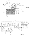
- the senor 1 is associated with a sealed container 2.
- the sensor 1 comprises a first sensor element 1a which is placed outside the container 2, and which comprises a first electrical circuit 1b.
- a second sensor element 1 c is placed inside the container 2, and comprises a second electrical circuit 1 d and means 1 e sensitive to the presence of a liquid 200 in the container 2.
- a wireless link 3 by magnetic induction without magnetic circuit is provided for transmitting electrical signals between the first electrical circuit 1b and the second electrical circuit 1 d, ensuring the transmission of liquid presence signals emitted by the second electric circuit 1d.
- the first electric circuit 1b comprises a primary coil 4
- the second electric circuit 1d comprises a secondary coil 9.
- the wireless link 3 between the first sensor element 1a and the second sensor element 1c is provided by the magnetic coupling between the primary 4 and secondary 9 coils.
- the coupling takes place through the wall of the container 2, without the aid of a continuous or closed magnetic circuit, with a ferromagnetic material such as those of the transformers.
- the container 2 is formed of a peripheral wall 2a provided with an insertion orifice 2b closable by a plug 2c.
- the plug 2c is open during assembly, for the introduction of the second sensor element 1c inside the container 2 and its attachment on the inner face of the wall 2a, against an intermediate zone 2d of the wall 2a 2.
- the cap 2c is then closed, and can be sealed, no opening being necessary later.
- first sensor element 1a and the second sensor element 1c respectively having a first electrical circuit 1b and a second electrical circuit 1d.
- the first electrical circuit 1b comprises the primary coil 4, an electric excitation circuit 5 capable of generating on the primary coil 4 excitation pulse voltages, and an electric analyzer circuit 6.
- the second electrical circuit 1 d is a secondary passive oscillating circuit 8, comprising the secondary coil 9 and a capacitor 10.
- the means sensitive to the presence of a liquid 200 in the container 2 is a variable impedance element 1 e whose impedance varies depending on whether liquid 200 is present or absent in the container 2 and whose impedance variation modifies the oscillation properties of the passive secondary oscillating circuit 8.
- variable impedance element 1 e comprises two electrical conductors 11 and 12, each connected to a respective terminal 13 or 14 of the capacitor 10, and each having an apparent conducting portion 11a or 12a to be in contact with the liquid 200 whose presence must be sought in the container 2.
- the two visible conductive parts 11a and 12a are separated by a gap 15 which can be occupied by liquid 200.
- the two electrical conductors 11 and 12 constitute, with the liquid 200 in the interval 15, a resistive element whose resistance value affects the properties of the passive secondary oscillating circuit 8.
- the electrical analyzer circuit 6 can therefore be arranged to detect the influence of this resistance on the oscillations of the passive secondary oscillating circuit 8, in order to detect the presence of liquid 200 between the two visible conductive parts 11a and 12a of the element variable impedance 1 e.
- the electric excitation circuit 5 comprises a switching element 16, such as a transistor driven by the electric analyzer circuit 6, and which has an on state and a blocked state.
- the switching element 16 is connected to periodically switch in series with the primary coil 4 a DC voltage source U.
- the DC voltage source may be the vehicle battery.
- a resistor 17 in series limits the electric current established in the primary coil 4 when the switching element 16 is in the on state.
- a stabilizing resistor 18 and a voltage limiting component 19 are connected in parallel across the primary coil 4.
- the voltage limiting component 19 may be for example a component based on Zener diodes.
- switching element 16 is switched on.
- An electric current is then established in the primary coil 4, and becomes rapidly continuous and of value determined by the resistor 17.
- the switching element 16 is then switched off, making a sudden disconnection of the DC voltage source U at the terminals of the primary coil 4.
- This disconnection causes the production, at the terminals of the primary coil 4, of a voltage step of high value, clipped by the voltage limiter component 19.
- This voltage step or very sudden change in voltage, generates a rapid variation of the magnetic field created by the primary coil 4 and which is transmitted to the secondary coil 9 through the wall 2a ( figure 1 ) of the container 2, which wall 2a is made of non-metallic material.
- the pulse received by the secondary coil 9 excites the passive secondary oscillating circuit 8, in which appears a damped sinusoidal electric oscillation whose shape (amplitude of voltage) is similar to that illustrated on FIG. figure 3 .
- This damped sinusoidal oscillation is transmitted from the secondary coil 9 to the primary coil 4 and propagates in the first circuit 1b as electrical signals 100 which comprise a damped sinewave component as illustrated in FIG. figure 3 .
- the resulting electrical signals 100 appearing in the first electrical circuit 1b are the image of the oscillation signals appearing in the passive secondary oscillating circuit 8.
- the electrical analyzer circuit 6 is programmed to scan and analyze the resulting electrical signals 100 during the time period following the moment when the switching element 16 goes from its on state to its off state.
- the electric circuit analyzer 6 is for that purpose implemented in a microcontroller which receives, after conditioning by an amplifying circuit not illustrated in the figures, the voltage at the terminals of the primary coil, or voltage taken at the measuring point 20.
- this voltage comprises a damped sinusoidal component as illustrated on the Figures 3 and 4 .
- the electrical analyzer circuit 6 must therefore, in this embodiment of the variable impedance element 1 e, compare the damping of the resulting electrical signals 100 which occur in the presence of liquid 200 with the damping which occurs in the no liquid 200.
- the electrical circuit analyzer 6 must compare the curves of the Figures 4 and 3 .
- the sensor according to the invention is operated in the absence of liquid to be detected.
- the electrical analyzer circuit 6 can generate a signal which is the derivative of the resulting electrical signals 100, and it stores the sequence of the amplitudes of the resulting electrical signals 100 at times when the sign of the signal derivative is reversed.
- the electrical circuit analyzer stores the amplitudes of the signal resulting from the figure 3 at times identified by the references A, B, C, D, E, F and G for example.
- This sequence of amplitudes A, B, C, D, E, F and G, recorded in a memory of the electric analyzer circuit 6, constitutes the reference parameters which will then make it possible, by comparison, to determine whether a conductive liquid 200 is present. in the container 2.
- the electrical analyzer circuit 6 can be used for the detection of the presence of liquid 200.
- the resulting electrical signals 100 have the appearance illustrated in FIG. figure 4 , and the same procedure as that previously used makes it possible to memorize the sequence of the amplitudes of the resulting electrical signals 100 at the instants A ', B', C ', D', E ', F' and G '.
- the electrical circuit analyzer 6 can then compare the two amplitude sequences. In the case of almost equality, the electrical analyzer circuit 6 deduces the absence of liquid 200. In case of difference, the electric analyzer circuit 6 can emit a signal indicating the presence of a liquid 200.
- the primary 4 and secondary 9 coils are arranged facing each other on either side of the intermediate zone 2d of the wall 2a of the container 2. It is only necessary that the intermediate zone 2d of the wall 2a of the container 2 is made of a material allowing the magnetic field to pass between the primary and secondary coils 4.
- the rest of the wall 2a of the container 2 can be made of the same material, or another material, for as far as its constitution does not disturb the transmission of the magnetic field between the two coils 4 and 9.
- the primary 4 and secondary 9 coils are arranged substantially coaxial with each other, and as close as possible to one another on either side of the intermediate zone 2d of the wall 2a. .
- the electrical conductors 11 and 12 of the variable impedance element 1 e may be oriented perpendicular to the plane of the secondary coil 9 as shown in FIG. figure 1 .
- these conductors may be oriented differently, for example parallel to the plane of the secondary coil 9, or in any other oblique orientation.
- the primary 4 and secondary 9 coils are placed in such a way that the electrical conductors of the variable impedance element 1 e are in the zone of the container 2 in which the presence of a liquid 200 is to be detected.
- the liquid presence sensor 1 is implanted in the diesel oil filtering and heating element of a diesel engine.
- the container 2 is sealed and is the filtering and reheating member itself.
- the first sensor element 1a is placed outside, and is therefore not in contact with the gas oil.
- the second sensor element 1c is placed inside the container, and therefore comes into contact with the gas oil.
- the sensor is intended to detect the presence of water in the gas oil.
- the output signal generated by the sensor 1 according to the present invention can then advantageously make it possible to control a purge solenoid valve capable of extracting the water detected in the gas oil.
- the microcontroller can be arranged to fulfill other intelligent functions that are necessary in the same environment of the sensor 1 and the sealed container 2.
- the microcontroller can control the purge valve, it can also control the means regulating the temperature of the fuel oil, and it can control other elements of a vehicle.
- the temperature of the gas oil can be regulated using for example a temperature sensor which gives information to the microcontroller, which drives heating elements immersed in the environment of the filter. Connectors and wiring are simplified.
Abstract
Description
La présente invention concerne les moyens pour détecter la présence d'un liquide dans un conteneur.The present invention relates to the means for detecting the presence of a liquid in a container.
On a déjà proposé de nombreux types de capteur de présence de liquide, notamment pour contrôler le niveau de liquide dans un conteneur.Many types of liquid presence sensors have already been proposed, in particular for controlling the level of liquid in a container.
Par exemple, le document
La traversée de paroi du conteneur induit un risque de fuite de liquide par des interstices pouvant se produire au passage des électrodes. Ce risque n'est pas acceptable dans les conteneurs étanches, surtout les conteneurs dans lesquels l'atmosphère intérieure peut être en surpression.The container wall crossing induces a risk of liquid leakage through gaps that may occur at the passage of the electrodes. This risk is not acceptable in sealed containers, especially containers in which the internal atmosphere may be overpressurized.
Si l'on dispose le passage des électrodes en partie supérieure du conteneur, le risque de fuite est réduit, mais il subsiste tout de même dans le cas où le liquide peut remplir complètement le conteneur.If we have the passage of the electrodes in the upper part of the container, the risk of leakage is reduced, but it still remains in the case where the liquid can completely fill the container.
On connaît par ailleurs du document
Les moyens sensibles à la présence d'un liquide dans le conteneur consistent en un transducteur à ultrasons, placé au-dessus du niveau du liquide, qui émet des ultrasons vers la surface du liquide et qui calcule le temps de vol des ultrasons réfléchis par le niveau de liquide.The means sensitive to the presence of a liquid in the container consist of an ultrasonic transducer, placed above the level of the liquid, which emits ultrasound towards the surface of the liquid and which calculates the flight time of the ultrasound reflected by the liquid level.
Les données de temps de vol sont ensuite transformées en données de hauteur de niveau de liquide, qui sont transmises au premier élément de capteur par la liaison sans fil à transmission d'ondes hertziennes au moyen de l'émetteur et du récepteur d'ondes hertziennes.The flight time data is then transformed into liquid level height data, which is transmitted to the first sensor element. by the wireless transmission link of radio waves by means of the transmitter and the receiver of radio waves.
On pourrait imaginer d'adapter ce dispositif à un conteneur totalement étanche, supprimant les risques de fuite, puisqu'il n'y a alors aucun élément devant traverser la paroi du conteneur.One could imagine to adapt this device to a completely sealed container, eliminating the risk of leakage, since there is then no element to pass through the wall of the container.
Cependant, un tel dispositif présente plusieurs inconvénients, qui empêchent son application à certains conteneurs à faible prix et/ou étanches.However, such a device has several disadvantages, which prevent its application to some containers at low prices and / or sealed.
Tout d'abord, un tel capteur doit comprendre un transducteur à ultrasons, un émetteur et un récepteur d'ondes hertziennes modulées, et des moyens de calcul, ce qui implique un coût relativement élevé.First of all, such a sensor must comprise an ultrasonic transducer, a transmitter and a modulated radio wave receiver, and calculation means, which implies a relatively high cost.
Par rapport au coût d'un réservoir de produits pétroliers, le coût de ce capteur est évidemment négligeable. Cependant, pour des applications à des réservoirs de plus petite taille ou de plus faible valeur, par exemple dans le domaine automobile, le coût de ce capteur devient prohibitif.Compared to the cost of a tank of petroleum products, the cost of this sensor is obviously negligible. However, for applications to smaller or lower value tanks, for example in the automotive field, the cost of this sensor becomes prohibitive.
Un second inconvénient est la nécessité d'alimenter le second élément de capteur à l'intérieur du conteneur par une source d'énergie électrique. Le document prévoit d'incorporer une pile dans le second élément de capteur. La durée de vie des piles est limitée, et nécessite alors une intervention périodique de changement de pile, et donc l'ouverture du conteneur. Cela constitue un inconvénient important dans le cas de conteneurs dont l'accès est difficile ou dangereux, par exemple les conteneurs à grande hauteur. Et surtout cela n'est pas acceptable dans le cas de conteneurs devant rester étanches sans intervention périodique de maintenance. Tel est le cas par exemple de certains conteneurs étanches utilisés dans le domaine automobile.A second drawback is the need to supply the second sensor element inside the container with a source of electrical energy. The document provides for incorporating a battery into the second sensor element. The life of the batteries is limited, and then requires periodic intervention battery change, and therefore the opening of the container. This is a significant disadvantage in the case of containers whose access is difficult or dangerous, for example high-rise containers. And especially this is not acceptable in the case of containers to remain sealed without periodic maintenance intervention. This is the case for example of certain sealed containers used in the automotive field.
On connaît aussi, du document
Dans le dispositif décrit dans ce document, des moyens sensibles à la présence de liquide sont disposés dans le conteneur et sont connectés au secondaire d'un transformateur à circuit magnétique dont le primaire est alimenté par un oscillateur dont les oscillations sinusoïdales sont étouffées lorsque du liquide présent dans le conteneur réduit l'impédance aux bornes du secondaire du transformateur. Le dispositif nécessite la traversée de paroi du conteneur, avec les risques de fuite que cela implique.In the device described in this document, means sensitive to the presence of liquid are arranged in the container and are connected to the secondary of a magnetic circuit transformer whose primary is fed by an oscillator whose sinusoidal oscillations are stifled when liquid present in the container reduces the impedance across the secondary of the transformer. The device requires the crossing of the container wall, with the risk of leakage that implies.
Le problème proposé par la présente invention est de concevoir une nouvelle structure de capteur qui permette la détection de présence de liquide dans un conteneur sans traversée de paroi par des organes électriques ou autres de nature à engendrer un risque de fuite, dont la structure soit particulièrement simple et peu onéreuse, et dont le coût de production soit ainsi compatible avec des applications telles que le domaine automobile.The problem proposed by the present invention is to design a new sensor structure that allows the detection of the presence of liquid in a container without wall penetration by electrical or other components of The nature of this system is to create a risk of leakage, the structure of which is particularly simple and inexpensive, and whose production cost is thus compatible with applications such as the automotive sector.
Selon un autre but, l'invention vise à réaliser un tel capteur dont la mise en place soit particulièrement aisée sans nécessiter des interventions de positionnement précises dans l'espace.According to another object, the invention aims to achieve such a sensor whose implementation is particularly easy without requiring precise positioning interventions in space.
Selon un autre aspect, l'invention vise à éviter toute intervention de maintenance périodique sur les éléments situés à l'intérieur du conteneur, afin de garantir l'intégrité du conteneur pendant une longue durée.According to another aspect, the invention aims at avoiding any periodic maintenance intervention on the elements situated inside the container, in order to guarantee the integrity of the container for a long time.
Selon un autre aspect, l'invention vise à éviter les effets d'électrolyse produits par des signaux électriques alternatifs de puissance non négligeable.According to another aspect, the invention aims to avoid the effects of electrolysis produced by alternative electrical signals of significant power.
Selon un autre aspect, l'invention prévoit d'appliquer un tel capteur au domaine automobile, et en particulier à la détection d'eau dans les filtres à gasoil des moteurs diesel. Cette fonction apparaît de plus en plus nécessaire avec le développement des moteurs diesel à haute pression, qui présentent un risque de destruction lors de la présence d'eau dans le gasoil.According to another aspect, the invention provides for applying such a sensor to the automobile field, and in particular to the detection of water in the diesel fuel filters of diesel engines. This function is becoming more and more necessary with the development of high-pressure diesel engines, which present a risk of destruction when water is present in the diesel.
Pour atteindre ces buts ainsi que d'autres, l'invention propose un capteur de présence de liquide pour conteneur, comprenant :
- un premier élément de capteur, destiné à être placé à l'extérieur du conteneur, et ayant un premier circuit électrique, comprenant une bobine primaire,
- un second élément de capteur ayant un second circuit électrique avec une bobine secondaire et avec des moyens sensibles à la présence d'un liquide dans le conteneur,
- un couplage magnétique entre les bobines primaire et secondaire des premier circuit électrique et second circuit électrique, pour transmettre au premier circuit électrique des signaux de présence du liquide émis par le second circuit électrique ;
selon l'invention : - le second circuit électrique est un circuit oscillant secondaire passif, comprenant la bobine secondaire et un condensateur, avec un élément à impédance variable, dont l'impédance varie selon que le liquide est présent ou absent, et dont la variation d'impédance modifie les propriétés d'oscillation du circuit oscillant secondaire passif,
- le couplage magnétique entre les bobines primaire et secondaire des premier élément de capteur et second élément de capteur est dépourvu de circuit magnétique continu,
- le premier circuit électrique comprend un circuit électrique d'excitation apte à générer sur la bobine primaire des tensions impulsionnelles d'excitation, et un circuit électrique analyseur,
- au cours d'une séquence d'analyse, le circuit électrique analyseur scrute les signaux électriques résultants qui apparaissent sur la bobine primaire à la suite de l'application d'une tension impulsionnelle d'excitation, compare des paramètres de ces signaux électriques résultants à des paramètres de référence, et génère un signal de sortie fonction du résultat de cette comparaison.
- a first sensor element, intended to be placed outside the container, and having a first electrical circuit, comprising a primary coil,
- a second sensor element having a second electrical circuit with a secondary coil and with means responsive to the presence of a liquid in the container,
- a magnetic coupling between the primary and secondary coils of the first electrical circuit and the second electrical circuit, for transmitting to the first electrical circuit presence signals of the liquid emitted by the second electrical circuit;
according to the invention: - the second electrical circuit is a passive secondary oscillating circuit, comprising the secondary coil and a capacitor, with a variable impedance element, the impedance of which varies according to whether the liquid is present or absent, and whose impedance variation modifies the properties oscillation of the passive secondary oscillating circuit,
- the magnetic coupling between the primary and secondary coils of the first sensor element and the second sensor element is devoid of a continuous magnetic circuit,
- the first electrical circuit comprises an electrical excitation circuit capable of generating excitation pulse voltages on the primary coil, and an electric analyzer circuit,
- during an analysis sequence, the electrical analyzer circuit scans the resulting electrical signals that appear on the primary coil as a result of the application of an excitation pulse voltage, compares parameters of these resulting electrical signals with reference parameters, and generates an output signal depending on the result of this comparison.
La liaison sans fil à transmission magnétique sans circuit magnétique continu, et l'absence de moyens d'alimentation externe du second élément de capteur, évitent toute traversée de la paroi du conteneur par des organes électriques ou autres, et évitent tout risque de fuite. Du fait que la liaison sans fil entre le premier élément de capteur et le second élément de capteur est assurée par le couplage magnétique sans circuit magnétique de deux bobines primaire et secondaire, les circuits électriques d'un tel capteur sont particulièrement simples, beaucoup plus simples que des émetteurs et récepteurs d'ondes hertziennes modulées.The wireless magnetic transmission link without a continuous magnetic circuit, and the absence of external power supply means of the second sensor element, avoid any crossing of the container wall by electrical or other organs, and avoid any risk of leakage. Since the wireless connection between the first sensor element and the second sensor element is provided by magnetic coupling without magnetic circuit of two primary and secondary coils, the electrical circuits of such a sensor are particularly simple, much simpler modulated radio transmitters and receivers.
En outre, un tel couplage entre deux bobines magnétiques de part et d'autre d'une paroi de conteneur peut présenter une qualité de transmission satisfaisante sans qu'il soit nécessaire d'utiliser des signaux alternatifs de forte puissance ou de placer de manière précise les bobines l'une par rapport à l'autre. Il en résulte une grande facilité d'adaptation du capteur dans un conteneur lors de la fabrication, et on limite au maximum l'effet d'électrolyse.In addition, such a coupling between two magnetic coils on either side of a container wall can have a satisfactory transmission quality without the need to use high power alternating signals or to precisely place the coils relative to each other. This results in a great ease of adaptation of the sensor in a container during manufacture, and the maximum electrolysis effect is limited.
Selon un mode de réalisation avantageux, le capteur selon l'invention est tel que :
- l'élément à impédance variable comprend deux conducteurs électriques, connectés chacun à une borne respective du condensateur, et ayant chacun une partie conductrice apparente pour être au contact du liquide à détecter dans le conteneur, de sorte que les deux conducteurs électriques constituent, avec un liquide conducteur de l'électricité, un élément à résistance variable dont la valeur de résistance dépend de la présence et de la concentration du liquide à détecter,
- le circuit électrique analyseur compare la composante d'amortissement des signaux électriques résultants à des valeurs de référence de composante d'amortissement.
- the variable impedance element comprises two electrical conductors, each connected to a respective terminal of the capacitor, and each having an apparent conductive portion for contacting the liquid to be detected in the container, so that the two electrical conductors constitute, with a electrically conductive liquid, a variable resistance element whose resistance value depends on the presence and the concentration of the liquid to be detected,
- the electric circuit analyzer compares the damping component of the resulting electrical signals with damping component reference values.
Dans ce cas, l'élément à impédance variable du capteur est une résistance électrique constituée par les deux conducteurs électriques et par la matière située dans l'intervalle entre les deux parties conductrices apparentes des conducteurs électriques. Lorsque les parties conductrices apparentes des conducteurs électriques sont dans l'air, elles sont isolées l'une de l'autre et la résistance électrique est très grande. Lorsque la matière située dans l'intervalle entre les deux parties conductrices apparentes des conducteurs électriques est un liquide électriquement isolant, la résistance est également grande. En présence d'eau dans l'intervalle entre les deux parties conductrices apparentes des conducteurs électriques, la résistance électrique est réduite, et modifie les propriétés du circuit oscillant secondaire passif. En particulier, lors d'une excitation par une tension impulsionnelle au primaire, dans le premier circuit électrique, le circuit oscillant secondaire passif entre en oscillation selon une onde sinusoïdale amortie dont l'amortissement dépend de la résistance électrique présente dans le circuit oscillant. Ainsi, la présence d'eau peut être détectée en analysant le taux d'atténuation de l'onde amortie dans le circuit oscillant secondaire passif, onde qui est transmise au premier circuit électrique à bobine primaire et qui est analysée par le circuit électrique analyseur.In this case, the variable impedance element of the sensor is an electrical resistance constituted by the two electrical conductors and by the material situated in the gap between the two visible conductive parts of the electrical conductors. When the visible conductive parts of the electrical conductors are in the air, they are isolated from each other and the electrical resistance is very large. When the material in the gap between the two visible conductive parts of the electrical conductors is an electrically insulating liquid, the resistance is also great. In the presence of water in the gap between the two apparent conductive parts of the electrical conductors, the electrical resistance is reduced, and modifies the properties of the passive secondary oscillating circuit. In particular, during an excitation by a primary impulse voltage, in the first electrical circuit, the passive secondary oscillating circuit oscillates according to a damped sine wave whose damping depends on the electrical resistance present in the oscillating circuit. Thus, the presence of water can be detected by analyzing the attenuation rate of the damped wave in the passive secondary oscillating circuit, which wave is transmitted to the first primary coil electrical circuit and is analyzed by the electric analyzer circuit.
On comprend qu'un tel capteur est particulièrement simple et peu onéreux, ne nécessitant aucun transducteur à ultrasons ou autre élément complexe.It is understood that such a sensor is particularly simple and inexpensive, requiring no ultrasonic transducer or other complex element.
Selon un mode de réalisation, pour analyser l'amortissement des signaux électriques résultants et les comparer à des valeurs de référence de composantes d'amortissement, le circuit électrique analyseur peut générer un signal qui est la dérivée des signaux électriques résultants, il peut mémoriser la suite des amplitudes des signaux électriques résultants à des instants où le signe du signal dérivé s'inverse, et il peut comparer la suite des amplitudes à une suite d'amplitudes de référence préalablement mémorisée.According to one embodiment, for analyzing the damping of the resulting electrical signals and comparing them with reference values of damping components, the electrical analyzer circuit can generate a signal which is the derivative of the resulting electrical signals, it can memorize the the amplitudes of the resulting electrical signals at times when the sign of the derived signal is reversed, and it can compare the sequence of amplitudes to a previously memorized sequence of reference amplitudes.
L'excitation du circuit oscillant secondaire passif peut être réalisée de manière particulièrement simple en prévoyant un circuit électrique d'excitation qui comprend un élément de commutation ayant un état passant et un état bloqué, apte à commuter périodiquement en série avec la bobine primaire une source de tension continue. A chaque commutation, la bobine primaire émet une impulsion magnétique transmise à la bobine secondaire et qui excite le circuit oscillant secondaire passif.The excitation of the passive secondary oscillating circuit can be carried out in a particularly simple manner by providing an electrical excitation circuit which comprises a switching element having an on state and a blocked state, able to periodically switch in series with the primary coil a source DC voltage. At each switching, the primary coil transmits a magnetic pulse transmitted to the secondary coil and which excites the passive secondary oscillating circuit.
De préférence, on considère essentiellement les signaux électriques résultants qui se produisent après l'instant où l'élément de commutation passe de son état passant vers son état bloqué. Le circuit électrique analyseur scrute alors et analyse les signaux électriques résultants, au cours de la période temporelle faisant suite à l'instant où l'élément de commutation passe de son état passant à son état bloqué. En effet, la commutation vers l'état bloqué est la configuration la plus favorable pour faciliter la détection et la mesure des paramètres des signaux électriques résultants dans le circuit électrique primaire : la bobine primaire subit une commutation rapide qui excite considérablement le circuit électrique secondaire, et simultanément la bobine primaire est déconnectée et ne subit plus l'influence de la source de tension continue, ce qui permet d'évaluer de façon plus précise les paramètres des oscillations de tension alternative amorties aux bornes de la bobine primaire.Preferably, the resulting electrical signals which occur after the moment when the switching element transitions from its on state to its off state are considered essentially. The electrical circuit analyzer then scans and analyzes the resulting electrical signals, during the time period following the moment when the switching element passes from its passing state to his blocked state. Indeed, switching to the off state is the most favorable configuration to facilitate the detection and measurement of the parameters of the resulting electrical signals in the primary electrical circuit: the primary coil undergoes a fast switching which greatly excites the secondary electrical circuit, and simultaneously the primary coil is disconnected and no longer undergoes the influence of the DC voltage source, which allows to evaluate more precisely the parameters of the AC voltage oscillations amortized across the primary coil.
Le circuit électrique analyseur peut avantageusement être implémenté dans un microcontrôleur qui reçoit, après conditionnement par un circuit amplificateur, la tension aux bornes de la bobine primaire. Un tel microcontrôleur peut aussi servir simultanément pour remplir d'autres fonctions intelligentes telles que le pilotage d'un élément de régulation de la température du gasoil, lorsque le capteur est appliqué au contrôle de présence d'eau dans le gasoil d'un moteur diesel.The electric circuit analyzer can advantageously be implemented in a microcontroller which receives, after conditioning by an amplifier circuit, the voltage across the primary coil. Such a microcontroller can also be used simultaneously to fulfill other intelligent functions such as the control of a diesel temperature control element, when the sensor is applied to the control of presence of water in the diesel fuel of a diesel engine. .
Les commutations de l'élément de commutation génèrent sur la bobine primaire une surtension initiale de valeur très élevée, que certains composants ne supportent pas. Pour éviter les risques de dégradation de composants, on peut avantageusement prévoir, dans le premier circuit électrique, une résistance de stabilisation et un composant limiteur de tension, connectés en parallèle aux bornes de la bobine primaire.Switching of the switching element generates on the primary coil an initial overvoltage of very high value, which some components do not support. To avoid the risk of component degradation, it is advantageous to provide, in the first electrical circuit, a stabilizing resistor and a voltage limiter component connected in parallel across the primary coil.
De préférence, la bobine secondaire, le condensateur et l'élément à impédance variable sont noyés en tout ou partie dans une résine.Preferably, the secondary coil, the capacitor and the variable impedance element are embedded wholly or partly in a resin.
Selon un autre aspect, l'invention propose un conteneur à parois non métalliques, équipé d'au moins un capteur de présence de liquide tel que défini ci-dessus. Le premier élément de capteur est placé et fixé à l'extérieur du conteneur, de façon définitive ou de façon amovible. Le second élément de capteur est placé et fixé à l'intérieur du conteneur. Les bobines primaire et secondaire sont positionnées en regard l'une de l'autre de part et d'autre d'une zone intermédiaire de paroi du conteneur.According to another aspect, the invention proposes a container with non-metallic walls, equipped with at least one liquid presence sensor as defined above. The first sensor element is placed and fixed to the outside of the container, permanently or removably. The second sensor element is placed and fixed inside the container. The primary and secondary coils are positioned facing each other on either side of an intermediate wall zone of the container.
On comprend que, une fois que le second élément de capteur est placé et fixé à l'intérieur du conteneur, il n'y a plus aucun besoin d'ouvrir le conteneur. En pratique, on peut prévoir une paroi étanche de conteneur, munie d'un orifice d'insertion permettant l'introduction du second élément de capteur, et obturable par un bouchon. Après fermeture, il n'y a plus aucun besoin d'ouvrir le conteneur pour le fonctionnement ou la maintenance du capteur selon l'invention, et le conteneur peut donc rester étanche pendant toute son utilisation.It is understood that once the second sensor element is placed and fixed inside the container, there is no longer any need to open the container. In practice, there can be provided a sealed container wall, provided with an insertion hole for the introduction of the second sensor element, and closable by a plug. After closing, there is no longer any need to open the container for operation or maintenance of the sensor according to the invention, and the container can remain sealed during its use.
De préférence, les bobines primaire et secondaire sont disposées sensiblement coaxiales et au plus près l'une de l'autre de part et d'autre de la zone intermédiaire de paroi.Preferably, the primary and secondary coils are arranged substantially coaxially and as close as possible to one another on either side of the intermediate wall zone.
Dans le cas d'une fixation amovible du premier élément de capteur, ce dernier constitue un élément portable permettant alors de vérifier successivement plusieurs conteneurs.In the case of a removable attachment of the first sensor element, the latter constitutes a portable element allowing then to successively check several containers.
Selon un autre aspect, l'invention propose une application aux filtres à gasoil pour moteur diesel, le conteneur constituant alors l'enveloppe d'un filtre à gasoil pour moteur diesel, le capteur de présence de liquide selon l'invention étant agencé pour détecter la présence d'eau dans le gasoil à l'intérieur du filtre à gasoil.According to another aspect, the invention proposes an application to diesel fuel filters, the container then constituting the casing of a diesel fuel filter, the liquid presence sensor according to the invention being arranged to detect the presence of water in the diesel inside the diesel filter.
Le signal de sortie produit par le capteur de présence de liquide selon l'invention peut être avantageusement utilisé pour commander une électrovanne de purge apte à extraire l'eau du gasoil.The output signal produced by the liquid presence sensor according to the invention can be advantageously used to control a purge solenoid valve capable of extracting water from the gas oil.
D'autres objets, caractéristiques et avantages de la présente invention ressortiront de la description suivante de modes de réalisation particuliers, faite en relation avec les figures jointes, parmi lesquelles :
- la
figure 1 est une vue schématique illustrant la structure générale d'un capteur de présence de liquide dans un conteneur étanche selon un mode de réalisation de la présente invention ; - la
figure 2 illustre le schéma électrique de principe du capteur selon un mode de réalisation de la présente invention ; - la
figure 3 est un diagramme temporel illustrant la forme d'onde (amplitude) des signaux électriques résultants dans le cas d'une absence de détection de liquide ; et - la
figure 4 est un diagramme temporel illustrant la forme d'onde (amplitude) des signaux électriques résultants dans le cas d'une détection de liquide conducteur de l'électricité.
- the
figure 1 is a schematic view illustrating the general structure of a liquid presence sensor in a sealed container according to an embodiment of the present invention; - the
figure 2 illustrates the principle electrical diagram of the sensor according to one embodiment of the present invention; - the
figure 3 is a timing diagram illustrating the waveform (amplitude) of the resulting electrical signals in the case of a lack of liquid detection; and - the
figure 4 is a timing diagram illustrating the waveform (amplitude) of the resulting electrical signals in the case of electrically conductive liquid detection.
Dans le mode de réalisation illustré sur la
Le capteur 1 comprend un premier élément de capteur 1 a que l'on place à l'extérieur du conteneur 2, et qui comprend un premier circuit électrique 1b. Un second élément de capteur 1 c est placé à l'intérieur du conteneur 2, et comprend un second circuit électrique 1 d et des moyens 1 e sensibles à la présence d'un liquide 200 dans le conteneur 2. Une liaison sans fil 3 par induction magnétique sans circuit magnétique est prévue pour transmettre des signaux électriques entre le premier circuit électrique 1b et le second circuit électrique 1 d, assurant la transmission de signaux de présence de liquide émis par le second circuit électrique 1d.The
On distingue, sur la
Le conteneur 2 est formée d'une paroi périphérique 2a munie d'un orifice d'insertion 2b obturable par un bouchon 2c. Le bouchon 2c est ouvert lors de l'assemblage, pour l'introduction du second élément de capteur 1 c à l'intérieur du conteneur 2 et sa fixation sur la face interne de la paroi 2a, contre une zone intermédiaire 2d de la paroi 2a du conteneur 2. Le bouchon 2c est ensuite refermé, et peut être scellé, aucune ouverture n'étant nécessaire ultérieurement.The
On considère maintenant la
On retrouve le premier élément de capteur 1 a et le second élément de capteur 1 c ayant respectivement un premier circuit électrique 1b et un second circuit électrique 1 d.We find the first sensor element 1a and the
Le premier circuit électrique 1 b comprend la bobine primaire 4, un circuit électrique d'excitation 5 apte à générer sur la bobine primaire 4 des tensions impulsionnelles d'excitation, et un circuit électrique analyseur 6.The first
Le second circuit électrique 1 d est un circuit oscillant secondaire passif 8, comprenant la bobine secondaire 9 et un condensateur 10. Le moyen sensible à la présence d'un liquide 200 dans le conteneur 2 est un élément à impédance variable 1 e dont l'impédance varie selon que du liquide 200 est présent ou absent dans le conteneur 2 et dont la variation d'impédance modifie les propriétés d'oscillation du circuit oscillant secondaire passif 8.The second
Dans le mode de réalisation illustré sur les figures, l'élément à impédance variable 1 e comprend deux conducteurs électriques 11 et 12, connectés chacun à une borne respective 13 ou 14 du condensateur 10, et ayant chacun une partie conductrice apparente 11 a ou 12a pour être au contact du liquide 200 dont la présence doit être recherchée dans le conteneur 2. Les deux parties conductrices apparentes 11 a et 12a sont séparées par un intervalle 15 pouvant être occupé par du liquide 200. En présence d'un liquide 200 conducteur de l'électricité dans l'intervalle 15, les deux conducteurs électriques 11 et 12 constituent, avec le liquide 200 dans l'intervalle 15, un élément résistif dont la valeur de résistance affecte les propriétés du circuit oscillant secondaire passif 8.In the embodiment illustrated in the figures, the variable impedance element 1 e comprises two
Le circuit électrique analyseur 6 peut donc être agencé de manière à détecter l'influence de cette résistance sur les oscillations du circuit oscillant secondaire passif 8, afin de détecter la présence de liquide 200 entre les deux parties conductrices apparentes 11a et 12a de l'élément à impédance variable 1 e.The electrical analyzer circuit 6 can therefore be arranged to detect the influence of this resistance on the oscillations of the passive secondary
Le circuit électrique d'excitation 5 comprend un élément de commutation 16, tel qu'un transistor piloté par le circuit électrique analyseur 6, et qui présente un état passant et un état bloqué. L'élément de commutation 16 est connecté de façon à commuter périodiquement en série avec la bobine primaire 4 une source de tension continue U. Par exemple, dans les applications au domaine automobile, la source de tension continue peut être la batterie du véhicule.The
Une résistance 17 en série limite le courant électrique s'établissant dans la bobine primaire 4 lorsque l'élément de commutation 16 est à l'état passant.A
Une résistance de stabilisation 18 et un composant limiteur de tension 19 sont connectés en parallèle aux bornes de la bobine primaire 4. Le composant limiteur de tension 19 peut être par exemple un composant à base de diodes Zener.A stabilizing
On considère maintenant le fonctionnement du circuit électrique de la
Initialement, on commute l'élément de commutation 16 à l'état passant. Un courant électrique s'établit alors dans la bobine primaire 4, et devient rapidement continu et de valeur déterminée par la résistance 17.Initially, switching
On commute alors l'élément de commutation 16 à l'état bloqué, réalisant une déconnexion brusque de la source de tension continue U aux bornes de la bobine primaire 4. Cette déconnexion provoque la production, aux bornes de la bobine primaire 4, d'un échelon de tension de forte valeur, écrêté par le composant limiteur de tension 19. Cet échelon de tension, ou variation très brusque de tension, génère une variation rapide du champ magnétique créé par la bobine primaire 4 et qui se transmet à la bobine secondaire 9 à travers la paroi 2a (
Cette oscillation sinusoïdale amortie est transmise de la bobine secondaire 9 vers la bobine primaire 4 et se propage dans le premier circuit électrique 1 b sous forme de signaux électriques résultants 100 qui comportent une composante à onde sinusoïdale amortie telle qu'illustrée sur la
Ainsi, les signaux électriques résultants 100 apparaissant dans le premier circuit électrique 1b sont l'image des signaux d'oscillation apparaissant dans le circuit oscillant secondaire passif 8.Thus, the resulting
En l'absence d'un liquide 200 conducteur de l'électricité dans l'intervalle 15 entre les parties conductrices apparentes 11a et 12a des conducteurs électriques 11 et 12, les oscillations du circuit oscillant secondaire passif 8 sont relativement peu amorties, comme illustré sur la
Par contre, en présence d'un liquide 200 conducteur de l'électricité dans l'intervalle 15, la conduction électrique possible dans l'intervalle 15 amortit plus rapidement les oscillations du circuit oscillant secondaire passif 8, de sorte que les signaux électriques résultants 100 deviennent plus rapidement amortis, comme illustré sur la
Le circuit électrique analyseur 6 est programmé pour scruter et analyser les signaux électriques résultants 100 au cours de la période temporelle qui fait suite à l'instant où l'élément de commutation 16 passe de son état passant vers son état bloqué. Le circuit électrique analyseur 6 est pour cela implémenté dans un microcontrôleur qui reçoit, après conditionnement par un circuit amplificateur non illustré sur les figures, la tension aux bornes de la bobine primaire, ou tension prise au point de mesure 20.The electrical analyzer circuit 6 is programmed to scan and analyze the resulting
Comme déjà indiqué, cette tension comporte une composante sinusoïdale amortie telle qu'illustrée sur les
Le circuit électrique analyseur 6 doit donc, dans ce mode de réalisation de l'élément à impédance variable 1 e, comparer l'amortissement des signaux électriques résultants 100 qui se produisent en présence de liquide 200 avec l'amortissement qui se produit en l'absence de liquide 200.The electrical analyzer circuit 6 must therefore, in this embodiment of the variable impedance element 1 e, compare the damping of the resulting
En d'autres termes, le circuit électrique analyseur 6 doit comparer les courbes des
Pour cela, dans un mode de réalisation, au cours d'une étape de mémorisation préalable, on fait fonctionner le capteur selon l'invention en l'absence de liquide à détecter. Des signaux électriques résultants 100 relativement peu amortis, tels qu'illustrés sur la
Ensuite, le circuit électrique analyseur 6 peut être utilisé pour la détection de présence de liquide 200. En présence de liquide 200, les signaux électriques résultants 100 ont l'allure illustrée sur la
En prévoyant un circuit électrique analyseur 6 qui peut détecter avec une bonne sensibilité les différences de paramètres d'amortissement dans les signaux électriques résultants 100, on peut aussi imaginer d'apprécier la concentration de liquide 200 conducteur de l'électricité dans le conteneur 2, dans le cas où la résistance électrique du milieu dans l'intervalle 15 varie de façon sensible avec cette concentration.By providing an electric analyzer circuit 6 which can detect the differences in damping parameters in the resulting
En considérant à nouveau la
De préférence, les bobines primaire 4 et secondaire 9 sont disposées sensiblement coaxiales l'une par rapport à l'autre, et au plus près l'une de l'autre de part et d'autre de la zone intermédiaire 2d de la paroi 2a.Preferably, the primary 4 and secondary 9 coils are arranged substantially coaxial with each other, and as close as possible to one another on either side of the
Les conducteurs électriques 11 et 12 de l'élément à impédance variable 1 e peuvent être orientés perpendiculairement par rapport au plan de la bobine secondaire 9 comme illustré sur la
On place les bobines primaire 4 et secondaire 9 de telle façon que les conducteurs électriques de l'élément à impédance variable 1 e se trouve dans la zone du conteneur 2 dans laquelle on veut détecter la présence d'un liquide 200.The primary 4 and secondary 9 coils are placed in such a way that the electrical conductors of the variable impedance element 1 e are in the zone of the
Selon une application importante de l'invention, le capteur 1 de présence de liquide est implanté dans l'organe de filtrage et de réchauffage du gasoil d'un moteur diesel. Dans ce cas, le conteneur 2 est étanche et est l'organe de filtrage et de réchauffage lui-même. Le premier élément de capteur 1 a est placé à l'extérieur, et n'est donc pas en contact avec le gasoil. Le second élément de capteur 1 c est placé à l'intérieur du conteneur, et vient donc en contact avec le gasoil. Le capteur a dans ce cas pour but de détecter la présence d'eau dans le gasoil.According to an important application of the invention, the
Le signal de sortie généré par le capteur 1 selon la présente invention peut alors avantageusement permettre de commander une électrovanne de purge, apte à extraire l'eau détectée dans le gasoil.The output signal generated by the
Une difficulté peut résulter de l'utilisation du microcontrôleur, qui est un élément susceptible d'augmenter le coût de production du dispositif. Dans ce cas, le microcontrôleur peut être agencé pour remplir d'autres fonctions intelligentes qui sont nécessaires dans le même environnement du capteur 1 et du conteneur étanche 2. Par exemple, le microcontrôleur peut piloter la vanne de purge, il peut aussi piloter les moyens de régulation de la température du gasoil, et il peut piloter d'autres éléments d'un véhicule.A difficulty may result from the use of the microcontroller, which is an element likely to increase the production cost of the device. In this case, the microcontroller can be arranged to fulfill other intelligent functions that are necessary in the same environment of the
La température du gasoil peut être régulée en utilisant par exemple un capteur de température qui donne une information au microcontrôleur, lequel pilote des éléments chauffants immergés dans l'environnement du filtre. Les connecteurs et le câblage sont ainsi simplifiés.The temperature of the gas oil can be regulated using for example a temperature sensor which gives information to the microcontroller, which drives heating elements immersed in the environment of the filter. Connectors and wiring are simplified.
La présente invention n'est pas limitée aux modes de réalisation qui ont été explicitement décrits, mais elle en inclut les diverses variantes et généralisations contenues dans le domaine des revendications ci-après.The present invention is not limited to the embodiments which have been explicitly described, but it includes the various variants and generalizations thereof within the scope of the claims below.
Claims (14)
caractérisé en ce que :
characterized in that
Applications Claiming Priority (1)
| Application Number | Priority Date | Filing Date | Title |
|---|---|---|---|
| FR0758332A FR2922302B1 (en) | 2007-10-15 | 2007-10-15 | SENSOR FOR PRESENCE OF LIQUID IN A CONTAINER AND DEVICE PROVIDED WITH SUCH SENSOR |
Publications (2)
| Publication Number | Publication Date |
|---|---|
| EP2051049A1 true EP2051049A1 (en) | 2009-04-22 |
| EP2051049B1 EP2051049B1 (en) | 2017-08-16 |
Family
ID=39591463
Family Applications (1)
| Application Number | Title | Priority Date | Filing Date |
|---|---|---|---|
| EP08166661.2A Active EP2051049B1 (en) | 2007-10-15 | 2008-10-15 | Sensor for the presence of liquid in a container and device equipped with such a sensor |
Country Status (2)
| Country | Link |
|---|---|
| EP (1) | EP2051049B1 (en) |
| FR (1) | FR2922302B1 (en) |
Cited By (3)
| Publication number | Priority date | Publication date | Assignee | Title |
|---|---|---|---|---|
| WO2011084231A1 (en) * | 2009-12-16 | 2011-07-14 | Robert Bosch Gmbh | Magnetic field communication system and method for vehicles |
| WO2011127334A3 (en) * | 2010-04-08 | 2011-12-29 | Access Business Group International Llc | Point of sale inductive systems and methods |
| US10161779B2 (en) | 2015-05-26 | 2018-12-25 | University Of Utah Research Foundation | Liquid level sensor measuring a characteristic indicative of inductive coupling |
Citations (6)
| Publication number | Priority date | Publication date | Assignee | Title |
|---|---|---|---|---|
| GB1128839A (en) | 1966-10-11 | 1968-10-02 | Thomas Electronics Ltd | Water level detectors |
| GB2065336A (en) * | 1979-11-23 | 1981-06-24 | Mackenzie J R S | Automatic level control system for an oil contaminant |
| GB2254429A (en) * | 1991-04-04 | 1992-10-07 | Birt Electronic Systems Ltd | Liquid level sensor |
| EP0907070A1 (en) | 1997-10-01 | 1999-04-07 | G. Cartier Electronique | Level indicator, in particular for a combustion engine cooling circuit of a motor vehicle |
| WO2003104785A1 (en) * | 2002-06-10 | 2003-12-18 | Radian Technology Limited | Measurement and monitoring system of dairy stock and plant |
| US20070084283A1 (en) | 2005-10-18 | 2007-04-19 | Bj Services Company | Safety tank level gauging system |
-
2007
- 2007-10-15 FR FR0758332A patent/FR2922302B1/en active Active
-
2008
- 2008-10-15 EP EP08166661.2A patent/EP2051049B1/en active Active
Patent Citations (6)
| Publication number | Priority date | Publication date | Assignee | Title |
|---|---|---|---|---|
| GB1128839A (en) | 1966-10-11 | 1968-10-02 | Thomas Electronics Ltd | Water level detectors |
| GB2065336A (en) * | 1979-11-23 | 1981-06-24 | Mackenzie J R S | Automatic level control system for an oil contaminant |
| GB2254429A (en) * | 1991-04-04 | 1992-10-07 | Birt Electronic Systems Ltd | Liquid level sensor |
| EP0907070A1 (en) | 1997-10-01 | 1999-04-07 | G. Cartier Electronique | Level indicator, in particular for a combustion engine cooling circuit of a motor vehicle |
| WO2003104785A1 (en) * | 2002-06-10 | 2003-12-18 | Radian Technology Limited | Measurement and monitoring system of dairy stock and plant |
| US20070084283A1 (en) | 2005-10-18 | 2007-04-19 | Bj Services Company | Safety tank level gauging system |
Cited By (10)
| Publication number | Priority date | Publication date | Assignee | Title |
|---|---|---|---|---|
| WO2011084231A1 (en) * | 2009-12-16 | 2011-07-14 | Robert Bosch Gmbh | Magnetic field communication system and method for vehicles |
| US9158290B2 (en) | 2009-12-16 | 2015-10-13 | Robert Bosch Gmbh | Magnetic field communication arrangement and method |
| WO2011127334A3 (en) * | 2010-04-08 | 2011-12-29 | Access Business Group International Llc | Point of sale inductive systems and methods |
| GB2492010A (en) * | 2010-04-08 | 2012-12-19 | Access Business Group Int Llc | Point of sale inductive systems and methods |
| CN103109165A (en) * | 2010-04-08 | 2013-05-15 | 捷通国际有限公司 | Point of sale inductive systems and methods |
| US8893977B2 (en) | 2010-04-08 | 2014-11-25 | Access Business Group International Llc | Point of sale inductive systems and methods |
| US9027840B2 (en) | 2010-04-08 | 2015-05-12 | Access Business Group International Llc | Point of sale inductive systems and methods |
| CN103109165B (en) * | 2010-04-08 | 2015-08-19 | 捷通国际有限公司 | Point of sale induction system and method |
| US9424446B2 (en) | 2010-04-08 | 2016-08-23 | Access Business Group International Llc | Point of sale inductive systems and methods |
| US10161779B2 (en) | 2015-05-26 | 2018-12-25 | University Of Utah Research Foundation | Liquid level sensor measuring a characteristic indicative of inductive coupling |
Also Published As
| Publication number | Publication date |
|---|---|
| FR2922302B1 (en) | 2009-12-11 |
| FR2922302A1 (en) | 2009-04-17 |
| EP2051049B1 (en) | 2017-08-16 |
Similar Documents
| Publication | Publication Date | Title |
|---|---|---|
| EP0314222B1 (en) | Electric energy transmission device | |
| EP2051049B1 (en) | Sensor for the presence of liquid in a container and device equipped with such a sensor | |
| FR2977390A1 (en) | ELECTRICAL PLUG AND ELECTRICAL ASSEMBLY THEREFOR. | |
| EP2432302B1 (en) | Device for protecting an electronic printed circuit board. | |
| EP2156201B1 (en) | System for emitting an electric pulse and device for capacitive decoupling for such a system | |
| EP2705343A1 (en) | Monitoring unit and method for detecting structural defects which can occur in an aircraft nacelle during use | |
| EP1944848A1 (en) | Device and method of measuring lightning currents | |
| EP0533873A1 (en) | Ultrasonic detector, detection method for liquid media and ultrasonic transmitter control method. | |
| FR2492539A1 (en) | DETECTION METHOD AND SYSTEM IN PARTICULAR FOR MONITORING INSTALLATIONS OR AUTOMATIONS | |
| FR2776781A1 (en) | DEVICE FOR CONTROLLING THE IMPEDANCE REDUCED ON THE ANTENNA OF AN ELECTROMAGNETIC LABEL | |
| EP3881237A1 (en) | Device and method for detecting an opening or an attempt to open a closed container | |
| EP1761968B1 (en) | System for monitoring a group of electrochemical cells and device therefor | |
| FR3079928A1 (en) | DIFFERENTIAL PASSIVE SENSOR BASED ON ELASTIC WAVE RESONATORS FOR CONTACT DETECTION MEASUREMENT AND TEMPERATURE MEASUREMENT | |
| FR3012649A1 (en) | STATE CHANGE DETECTION OF ACTUATOR | |
| FR3066591A1 (en) | METHOD FOR OPTIMIZING THE DESIGN OF A DEVICE COMPRISING INTERROGATION MEANS AND A PASSIVE SENSOR REMOTE | |
| FR2922371A1 (en) | CONNECTION CONTROL DEVICE, AND CONNECTORS PROVIDED WITH SUCH A DEVICE | |
| EP4080791B1 (en) | Method for operating an acoustic transmission system for optimising the power transmitted | |
| EP4071451B1 (en) | Pressure sensor for a fluid circuit or for a sealed enclosure of a motor vehicle | |
| EP2543092B1 (en) | Assembly including an electric apparatus and a power supply battery sharing an oscillating circuit | |
| FR3139150A1 (en) | JOINERY WITH DETECTION OF THE POSITION OF THE OPENING IN RELATION TO THE FRAME | |
| EP3203198A1 (en) | An immersion detector and an aircraft | |
| EP3520184B1 (en) | Method for testing a semiconductor spark plug | |
| FR2962244A1 (en) | Film reel containing metal cylinder case opening detecting device for metal case monitoring system, has oscillator circuit coupled to metal case, and detection circuit connected to output of oscillator circuit to trigger alarm | |
| WO2004074826A1 (en) | Device and method for the simultaneous measurement of the extent and temperature of a fissure in the surface of a solid electrically-conducting body | |
| FR3112855A1 (en) | CAPACITIVE EFFECT LEAK DETECTION SYSTEM AND METHOD |
Legal Events
| Date | Code | Title | Description |
|---|---|---|---|
| PUAI | Public reference made under article 153(3) epc to a published international application that has entered the european phase |
Free format text: ORIGINAL CODE: 0009012 |
|
| AK | Designated contracting states |
Kind code of ref document: A1 Designated state(s): AT BE BG CH CY CZ DE DK EE ES FI FR GB GR HR HU IE IS IT LI LT LU LV MC MT NL NO PL PT RO SE SI SK TR |
|
| AX | Request for extension of the european patent |
Extension state: AL BA MK RS |
|
| 17P | Request for examination filed |
Effective date: 20091007 |
|
| 17Q | First examination report despatched |
Effective date: 20091102 |
|
| AKX | Designation fees paid |
Designated state(s): DE FR IT |
|
| GRAP | Despatch of communication of intention to grant a patent |
Free format text: ORIGINAL CODE: EPIDOSNIGR1 |
|
| INTG | Intention to grant announced |
Effective date: 20170331 |
|
| GRAS | Grant fee paid |
Free format text: ORIGINAL CODE: EPIDOSNIGR3 |
|
| GRAA | (expected) grant |
Free format text: ORIGINAL CODE: 0009210 |
|
| AK | Designated contracting states |
Kind code of ref document: B1 Designated state(s): DE FR IT |
|
| REG | Reference to a national code |
Ref country code: DE Ref legal event code: R096 Ref document number: 602008051617 Country of ref document: DE |
|
| REG | Reference to a national code |
Ref country code: FR Ref legal event code: PLFP Year of fee payment: 10 |
|
| REG | Reference to a national code |
Ref country code: DE Ref legal event code: R097 Ref document number: 602008051617 Country of ref document: DE |
|
| PLBE | No opposition filed within time limit |
Free format text: ORIGINAL CODE: 0009261 |
|
| STAA | Information on the status of an ep patent application or granted ep patent |
Free format text: STATUS: NO OPPOSITION FILED WITHIN TIME LIMIT |
|
| 26N | No opposition filed |
Effective date: 20180517 |
|
| REG | Reference to a national code |
Ref country code: FR Ref legal event code: PLFP Year of fee payment: 11 |
|
| P01 | Opt-out of the competence of the unified patent court (upc) registered |
Effective date: 20230505 |
|
| PGFP | Annual fee paid to national office [announced via postgrant information from national office to epo] |
Ref country code: FR Payment date: 20230907 Year of fee payment: 16 |
|
| PGFP | Annual fee paid to national office [announced via postgrant information from national office to epo] |
Ref country code: IT Payment date: 20231010 Year of fee payment: 16 Ref country code: DE Payment date: 20231011 Year of fee payment: 16 |