EP2056401A1 - Transmission line loaded dual-band monopole antenna - Google Patents
Transmission line loaded dual-band monopole antenna Download PDFInfo
- Publication number
- EP2056401A1 EP2056401A1 EP08011129A EP08011129A EP2056401A1 EP 2056401 A1 EP2056401 A1 EP 2056401A1 EP 08011129 A EP08011129 A EP 08011129A EP 08011129 A EP08011129 A EP 08011129A EP 2056401 A1 EP2056401 A1 EP 2056401A1
- Authority
- EP
- European Patent Office
- Prior art keywords
- transmission line
- monopole antenna
- terminal
- dual
- short
- Prior art date
- Legal status (The legal status is an assumption and is not a legal conclusion. Google has not performed a legal analysis and makes no representation as to the accuracy of the status listed.)
- Ceased
Links
Images


Classifications
-
- H—ELECTRICITY
- H01—ELECTRIC ELEMENTS
- H01Q—ANTENNAS, i.e. RADIO AERIALS
- H01Q9/00—Electrically-short antennas having dimensions not more than twice the operating wavelength and consisting of conductive active radiating elements
- H01Q9/04—Resonant antennas
- H01Q9/30—Resonant antennas with feed to end of elongated active element, e.g. unipole
-
- H—ELECTRICITY
- H01—ELECTRIC ELEMENTS
- H01Q—ANTENNAS, i.e. RADIO AERIALS
- H01Q5/00—Arrangements for simultaneous operation of antennas on two or more different wavebands, e.g. dual-band or multi-band arrangements
- H01Q5/30—Arrangements for providing operation on different wavebands
- H01Q5/307—Individual or coupled radiating elements, each element being fed in an unspecified way
- H01Q5/342—Individual or coupled radiating elements, each element being fed in an unspecified way for different propagation modes
- H01Q5/357—Individual or coupled radiating elements, each element being fed in an unspecified way for different propagation modes using a single feed point
- H01Q5/364—Creating multiple current paths
Definitions
- the present invention relates to the field of monopole antenna, and in particular to a transmission line loaded dual-band monopole antenna.
- WLAN Wireless Local Area Network
- Bluetooth Wireless Local Area Network
- HyperLAN HyperLAN
- IEEE Institute of Electrical and Electronics Engineers
- Taiwan Patent Publication No. M241815 discloses a dual-band monopole antenna, wherein the dual-band monopole antenna comprises a substrate, a dual frequency resonance antenna unit, a metal line, and a grounding metal line.
- the substrate defines a vertical direction and a horizontal direction.
- the dual frequency resonance antenna unit is comprised of a low-frequency radiation element and a high-frequency radiation element.
- the two radiation elements of the dual frequency resonance antenna unit are made up of lines of different lengths and are formed on the substrate in a direction substantially parallel to the vertical direction of the substrate.
- the dual frequency resonance antenna unit receives vertical polarization components of the high-frequency and low-frequency signals respectively.
- the line length of the low-frequency radiation element is greater than that of the high-frequency radiation element.
- Both the low-frequency and the high-frequency radiation elements can be formed as repeatedly curved/bent metal traces.
- the metal line is of an L-shape and is formed on the substrate.
- a long branch of the metal line is substantially parallel to the substrate horizontal direction and connected to terminals of the two radiation elements of the dual frequency resonance antenna unit for connection with a signal feeding line of a coaxial cable.
- a short branch of the metal line is arranged in a direction parallel to the substrate vertical direction.
- the grounding metal line is formed on the substrate and is substantially parallel to the substrate horizontal direction and is connected to the short branch of the metal line for connection with a shielding metal layer of the coaxial cable.
- the metal line and the grounding metal line are arranged at unsymmetrical locations to connect to the signal feeding line and the shielding metal layer of the coaxial cable so that the horizontal polarization components do not compensate each other.
- a dual-band resonance antenna unit comprised of a low-frequency radiation element and a high-frequency radiation element is needed.
- conventionally, to shorten the overall size of a monopole antenna by repeatedly bending the low-frequency and high-frequency radiation elements makes the manufacturing process of the metal traces of the radiation elements complicated and also increases the manufacturing costs.
- an objective of the present invention is to provide a transmission line loaded monopole antenna, wherein resonance in two bands, which is conventionally realized by two monopole antennas, is made possible with a single antenna, while the antenna is maintained in an elongate and slender configuration to facilitate assembling of the antenna.
- Another objective of the present invention is to provide a dual-band monopole antenna that is easy to make with a simplified manufacturing process.
- the technical solution adopted in the present invention to overcome the above discussed drawbacks includes a transmission line load that is connected in series to a monopole antenna and has a length smaller than a quarter of the wavelength in a designated operation frequency band to serve as an inductive load for reducing a second resonant frequency so as to realize operations in dual bands with a single monopole antenna.
- the monopole antenna comprises an antenna body, a signal feeding terminal, and a load connection terminal.
- An end of the antenna body forms the signal feeding terminal to which a signal feeding line is connected and an opposite end forms the load connection terminal to which the transmission line load that serves as the load is connected.
- the transmission line load comprises a core transmission line, an outer circumferential conductor, a dielectric layer, and a short-circuit section.
- the core transmission line which serves as a core conductor, has an antenna connection terminal and a short-circuit terminal.
- the antenna connection terminal is connected to the load connection terminal of the monopole antenna.
- the outer circumferential conductor comprises a circumferentially-extending outer conductor ring that circumferentially surrounds and is spaced from the core transmission line by a given distance, and can be constituted by a screen shield or sheath of a coaxial cable.
- the outer circumferential conductor has an open terminal and a short-circuit terminal. The open terminal of the outer circumferential conductor is close to the monopole antenna so that the outer circumferential conductor forms an open structure facing the monopole antenna.
- the dielectric layer is interposed between the core transmission line and the outer circumferential conductor.
- the short-circuit section is connected between the short-circuit terminal of the core transmission line and the short-circuit terminal of the outer circumferential conductor.
- the monopole that is externally added with a transmission line load features incorporation of an inductive load provided by the transmission line structure of the transmission line load and thus realizes control over high-order resonant frequency. Therefore, the present invention provides a monopole antenna that includes a transmission line load serving as an inductive load, whereby resonance in dual bands that is realized conventionally by two monopole antennas of different line lengths is made possible with a single monopole.
- the transmission line loaded dual-band monopole antenna in accordance with the present invention can be of the advantages of easy manufacturing and maintaining the slender configuration in practical applications. Further, a single bending can be adopted to shorten the appearance length of the monopole antenna of the present invention, enhancing the applicability of the monopole antenna of the present invention in modem compact and light-weighted portable electronic devices.
- the transmission line loaded dual-band monopole antenna of the present invention is operative in dual bands and is constructed as a monopole antenna added with a transmission line loaded antenna (TLLA) that is loaded with a transmission line.
- the transmission line that provides the load can be made up of, for example a coaxial cable, parallel conductors, a flexible metal tube or a spiral tube body, and can be positioned at a tail end of the antenna or at a location adjacent to a signal feeding terminal.
- the spatial relationship between the transmission line load and the antenna itself is arranged as shown in Figure 1 , and can also be referred to in Figure 2 , which is a cross-sectional view taken along line 2-2 of Figure 1 .
- the monopole antenna 1 comprises an antenna body 11, a signal feeding terminal 12, and a load connection terminal 13.
- An end of the antenna body 11 forms the signal feeding terminal 12, and an opposite end forms the load connection terminal 13 and is connected to a transmission line load 2 that serves a load of the antenna.
- the transmission line load 2 of the present invention is arranged at a distant location with respect to the signal feeding terminal.
- the transmission line load 2 comprises a core transmission line 21, an outer circumferential conductor 22, a dielectric layer 23, and a short-circuit section 24.
- the core transmission line 21, which serves as a core conductor is made of for example copper parts, copper-plated aluminum parts, or copper-plated steel parts and has an antenna connection terminal 211 and a short-circuit terminal 212.
- the antenna connection terminal 211 is connected to the load connection terminal 13 of the monopole antenna 1.
- the outer circumferential conductor 22 comprises a circumferentially-extending outer conductor ring that is arranged to circumferentially surround and spaced from the core transmission line 21 by a given distance, and can be constituted by a screen shield or sheath of a coaxial cable.
- the outer circumferential conductor 22 has an open terminal 221 and a short-circuit terminal 222 .
- the open terminal 221 of the outer circumferential conductor 22 is close to the monopole antenna 1 so that the outer circumferential conductor 22 forms an open structure facing the monopole antenna 1.
- the short-circuit terminal 222 is connected to the short-circuit terminal 212 of the core transmission line 21.
- the dielectric layer 23 is interposed between the core transmission line 21 and the outer circumferential conductor 22.
- the dielectric layer 23 can be for example air dielectric or made up of a non-conductive, insulation dielectric material, such as foamed polyethylene.
- the short-circuit section 24 is extended from the short-circuit terminal 212 of the core transmission line 21 to provide the short-circuit terminal 212 of the core transmission line 21 with a short-circuiting structure.
- the present invention is made to resemble the effect by providing a monopole antenna that is loaded by a transmission line structure that serves as a transmission line load 2.
- the transmission line load 2 itself can serve as a short-circuited transmission line.
- the length of the transmission line load 2 is substantially identical to a quarter of the wavelength of the second resonant frequency, it can serve as an inductive load connected in series to the monopole antenna 1.
- the inductive load can affect the high frequency of the second resonance.
- the second resonant frequency can be controlled by properly adjusting the length of the transmission line load 2 to eventually provide the monopole antenna 1 with the operability in dual bands.
- the length of the antenna body 11 of the monopole antenna 1 is set as "monopole antenna length LR"
- the length between the short-circuit terminal 222 of the outer circumferential conductor 22 of the transmission line load 2 and the open terminal 221 of the outer circumferential conductor 22 is "short-circuit transmission line length LT”
- the length of the short-circuit section 24 of the transmission line load 2 is "extension section length LE”.
- the overall length LA of the transmission line loaded dual-band monopole antenna of the present invention is thus the sum of the monopole antenna length LR plus the short-circuit transmission line length LT and the extension section length LE.
- the short-circuit transmission line length LT of the transmission line load 2 is set to be the equivalent quarter of the wavelength of a desired second resonant frequency
- the monopole antenna length LR is also set to be the equivalent quarter of the wavelength of the desired second resonant frequency
- the second resonant frequency is determined by the monopole antenna length LR.
- the monopole antenna length LR can set the second resonance at a given frequency, while the first resonant frequency, which is low frequency, is determined by the overall length LA and can be adjusted using the extension section length LE.
- Figure 3 shows voltage standing wave ratio curves obtained by varying a parameter representing the transmission load length. Under the condition that the overall length LA and the monopole antenna length LR are both fixed, the influence on the frequency response is observed by varying the parameter of the short-circuit transmission line length LT to for example 24mm, 27mm, and 30mm.
- the extension section length LE varies in accordance with the variation of the short-circuit transmission line length LT. It is observed from the curves that the high-frequency resonant frequency can be controlled by the short-circuit transmission line length LT solely but the low-frequency resonant frequency is not affected by the variation of the short-circuit transmission line length LT.
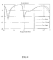
- Figure 4 shows voltage standing wave ratio curves obtained by varying the parameter representing the overall length of the combined transmission line load and the monopole antenna. Under the condition that the short-circuit transmission line length LT and the monopole antenna length LR are fixed, observation on the influence of the frequency response caused by only varying the overall length LA is carried out.
- the desired factor for changing the overall length LA is the extension section length LE, which is respectively set to 0mm, 2.5mm, and 5mm. It is observed from the curves that the low-frequency resonant frequency can be controlled by the extension section length LE or the overall length LA solely, but the high-frequency resonant frequency is not affected.
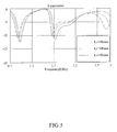
- Figure 5 shows voltage standing wave ratio curves obtained by varying the parameter representing the monopole antenna length. Under the condition that the short-circuit transmission line length LT is fixed, observation of the influence of the frequency response by only varying the monopole antenna length LR is made.
- Changing the parameter representing the monopole antenna length LR to for example 40mm, 44mm, and 48mm causes the overall length LA to change accordingly. It is observed from the curves that both low-frequency and high-frequency resonant frequencies are shifted together and this can be used to make desired shifting of the overall frequency for the transmission line loaded dual-band monopole antenna in accordance with the present invention.
- the transmission line loaded dual-band monopole antenna features high precision control of frequency realized by the independent adjustability of the high frequency and low frequency of the dual bands thereof and the simultaneous shifting of both the high and low frequencies.
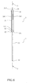
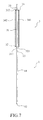
- Figure 6 shows a perspective view of a transmission line loaded dual-band monopole antenna constructed in accordance with a second embodiment of the present invention, which is also shown in Figure 7 , which is a cross-sectional view taken along line 7-7 of Figure 6 .
- An end of an antenna body 11 forms a signal feeding terminal 12, and an opposite end forms a load connection terminal 13 and is connected to a parallel-conductor transmission line that replaces the coaxial cable transmission line of the first embodiment.
- the parallel-conductor transmission line load 3 comprises a core transmission line 31, a carrier ring 32, a support ring 33, and a pair of parallel and spaced conductors 341, 342.
- the core transmission line 31, which serves as a core conductor, has an antenna connection terminal 311 and a short-circuit terminal 312.
- the antenna connection terminal 311 is connected to a load connection terminal 13 of a monopole antenna 1.
- the carrier ring 32 and the support ring 33 are respectively arranged on upper and lower ends of the core transmission line 31 and are spaced from the core transmission line 31 by a given distance.
- the carrier ring 32 is set at the antenna connection terminal 311 of the core transmission line 31 and forms an open terminal 321.
- the support ring 33 is set close to the short-circuit terminal 312 of the core transmission line 31.
- the carrier ring 32 and the support ring 33 are connected to each other by the pair of parallel conductors 341, 342.
- the two conductors 341, 342 is isolated from and spaced from the core transmission line 31 by a given distance by for example air dielectric or a non-conductive, insulation dielectric material, such as foamed polyethylene.
- the core transmission line 31 extends beyond the top of the support ring 332 to form a short-circuit section 35.
- the outer circumferential conductor 22 of the transmission line load 2 in the first embodiment is now replaced by two opposite conductors 341, 342 of the second embodiment.
- Figure 8 shows a perspective view of a transmission line loaded dual-band monopole antenna constructed in accordance with a third embodiment of the present invention, which is also shown in Figure 9 , which is a cross-sectional view taken along line 9-9 of Figure 8 .
- a monopole antenna 1 has an antenna body 11 having an end that forms a signal feeding terminal 12, and an opposite end forming a load connection terminal 13 connected to a transmission line load 4.
- the transmission line load 4 comprises a core transmission line 41, an outer circumferential conductor 42, a dielectric layer 43, and a short-circuit section 44.
- the core transmission line 41 has an antenna connection terminal 411 that is connected to the load connection terminal 13 and a short-circuit terminal 412.
- the outer circumferential conductor 42 comprises a circumferentially-extending outer conductor ring that circumferentially surrounds and is spaced from the core transmission line 41 by a given distance, and is formed by a flexible metal tube.
- the outer circumferential conductor 42 has an open terminal 421 and a short-circuit terminal 422.
- the open terminal 421 of the outer circumferential conductor 42 is close to the monopole antenna 1 so that the outer circumferential conductor 42 forms an open structure facing the monopole antenna 1.
- the dielectric layer 43 is interposed between the core transmission line 41 and the outer circumferential conductor 42.
- the short-circuit section 44 is connected between the short-circuit terminal 412 of the core transmission line 41 and the short-circuit terminal 422 of the outer circumferential conductor 42.
- Figure 10 shows a perspective view of a transmission line loaded dual-band monopole antenna constructed in accordance with a fourth embodiment of the present invention, which is also shown in Figure 11 , which is a cross-sectional view taken along line 11-11 of Figure 10 .
- a monopole antenna 1 comprises antenna body 11 having an end that forms a signal feeding terminal 12, and an opposite end forming a load connection terminal 13 connected to a transmission line load 5.
- the transmission line load 5 comprises a core transmission line 51, an outer circumferential conductor 52, a dielectric layer 53, and a short-circuit section 54.
- the core transmission line 51 has an antenna connection terminal 511 that is connected to the load connection terminal 13 and a short-circuit terminal 512.
- the outer circumferential conductor 52 comprises a circumferentially-extending outer conductor ring that circumferentially surrounds and is spaced from the core transmission line 51 by a given distance, and is formed by a support ring 521 and a spiral tube body 522 that is comprised of a plurality of tightly-engaging turns with zero spacing therebetween.
- the spiral tube body 522 has an end connected to the closed support ring 521 and forms an open structure close to the load connection terminal 13 of the monopole antenna 1.
- the dielectric layer 53 is interposed between the core transmission line 51 and the outer circumferential conductor 52.
- the short-circuit section 54 is connected between the short-circuit terminal 512 of the core transmission line 51 and the support ring 521 of the outer circumferential conductor 52.
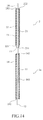
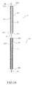
- Figure 12 shows a transmission line loaded dual-band monopole antenna constructed in accordance with a fifth embodiment of the present invention, wherein the transmission line load 2 is folded to shorten an appearance length of the transmission line without affecting the length of the transmission path.
- the transmission line load 2 of Figure 12 comprises a coaxial cable transmission line, which is bent and folded to shorten the appearance length of the transmission line.
- Figure 13 shows a transmission line loaded dual-band monopole antenna constructed in accordance with a sixth embodiment of the present invention and Figures 14 , 15 and 16 show variation embodiments of an outer conductor of the antenna of Figure 13 .
- the transmission line load 2 comprises a core transmission line 21 having an antenna connection terminal 211 that is connected to a load connection terminal 13 of an monopole antenna 1a and a short-circuit terminal 212.
- the core transmission line 21 is circumferentially surrounded by an outer circumferential conductor 22 that has an open terminal 221 forming an open structure with the opening facing the monopole antenna 1a and an opposite terminal that is closed and forms a short-circuit terminal 222.
- a dielectric layer 23 is interposed between the core transmission line 21 and the outer circumferential conductor 22.
- the short-circuit section 24 is connected between the short-circuit terminal 212 of the core transmission line 21 and the short-circuit terminal 222 of the outer circumferential conductor 22.
- the monopole antenna 1a is further surrounded by an outer conductor 14 in the form of a coaxial cable in the portion adjacent to a signal feeding terminal 12. Both ends of the outer conductor 14 form closed terminals 141, 142, this being different from the outer circumferential conductor 22 that has an open structure formed by an open terminal 221.
- a dielectric layer 143 is interposed between an antenna body 11 of the monopole antenna 1a and the outer conductor 14.
- the outer conductor 14 added to the monopole antenna 1a provides the antenna body 11 with a section having a relatively large diameter to realize a great bandwidth.
- the monopole antenna 1a is alternatively surrounded by an outer circumference tubular body 15 having opposite ends that are closed terminals 151, 152.
- a dielectric layer 153 is interposed between the antenna body 11 of the monopole antenna 1a and the outer circumference tubular body 15.
- the outer circumference tubular body 15 added to the monopole antenna 1a provides a section of relatively large diameter to realize a great bandwidth.
- the monopole antenna 1a is alternatively surrounded by an outer spiral body 16 having opposite ends that are closed and form support rings 161, 162.
- a dielectric layer 163 is interposed between an antenna body 11 of the monopole antenna 1a and the outer spiral body 16.
- the outer spiral body 16 added to the monopole antenna 1a provides the antenna body 11 with a section having a relatively large diameter to realize a great bandwidth.
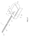
- Figure 17 shows a perspective view of a transmission line loaded dual-band monopole antenna constructed in accordance with a seventh embodiment of the present invention.
- An enclosure 6 of an electronic device has a surface forming in a suitable location an antenna mounting hole 61.
- the signal feeding terminal 12 of the monopole antenna 1a is mounted to the surface of the enclosure 6 through the antenna mounting hole 61 defined in the surface of the enclosure 6.
- the signal feeding terminal 12 of the monopole antenna 1a that extends through the antenna mounting hole 61 defined in the surface of the enclosure 6 is set in connection with a circuit board 62 that mates the monopole antenna 1a.
- the circuit board 62 is arranged at an end of the enclosure 6.
- a hot wire 631 of an end of a feeding signal transmission path 63 is connected to the signal feeding terminal 12 of the monopole antenna 1a and an opposite end serves as a grounding wire connected to the enclosure to thereby make the enclosure 6 a portion of the monopole antenna 1a.
Abstract
Description
- The present invention relates to the field of monopole antenna, and in particular to a transmission line loaded dual-band monopole antenna.
- With the popularization of the Internet, network connection becomes an important part of daily life. Wireless network connection that is not subjected to any physical and location constraint is getting prevailing. Further, various portable electronic devices, such as personal digital assistant (PDA), mobile phone, and notebook computer, are made compact and light-weighted generation by generation, providing enhanced portability and as a consequence, wireless techniques are now expanded to wide applications.
- Nowadays, various communication protocols set in accordance with the specifications and standards of various wireless digital transmission techniques, such as WLAN (Wireless Local Area Network), Bluetooth, HyperLAN, and IEEE (Institute of Electrical and Electronics Engineers), are employed in wireless communication. And, to provide satisfactory wireless communication on the basis of these protocols, various designs of antenna are available.
- The currently available antenna can be classified as dipole antenna, monopole antenna, planar antenna, loop antenna, and disk antenna. Various techniques have been developed for all these kinds of antenna. For patent documents that are currently known, Taiwan Patent Publication No.
M241815 - The two radiation elements of the dual frequency resonance antenna unit are made up of lines of different lengths and are formed on the substrate in a direction substantially parallel to the vertical direction of the substrate. The dual frequency resonance antenna unit receives vertical polarization components of the high-frequency and low-frequency signals respectively. The line length of the low-frequency radiation element is greater than that of the high-frequency radiation element. Both the low-frequency and the high-frequency radiation elements can be formed as repeatedly curved/bent metal traces.
- The metal line is of an L-shape and is formed on the substrate. A long branch of the metal line is substantially parallel to the substrate horizontal direction and connected to terminals of the two radiation elements of the dual frequency resonance antenna unit for connection with a signal feeding line of a coaxial cable. A short branch of the metal line is arranged in a direction parallel to the substrate vertical direction.
- The grounding metal line is formed on the substrate and is substantially parallel to the substrate horizontal direction and is connected to the short branch of the metal line for connection with a shielding metal layer of the coaxial cable.
- The metal line and the grounding metal line are arranged at unsymmetrical locations to connect to the signal feeding line and the shielding metal layer of the coaxial cable so that the horizontal polarization components do not compensate each other.
- However, for the known monopole antennas of any design, to realize resonance in two bands, a dual-band resonance antenna unit comprised of a low-frequency radiation element and a high-frequency radiation element is needed. In addition, conventionally, to shorten the overall size of a monopole antenna by repeatedly bending the low-frequency and high-frequency radiation elements makes the manufacturing process of the metal traces of the radiation elements complicated and also increases the manufacturing costs.
- Thus, an objective of the present invention is to provide a transmission line loaded monopole antenna, wherein resonance in two bands, which is conventionally realized by two monopole antennas, is made possible with a single antenna, while the antenna is maintained in an elongate and slender configuration to facilitate assembling of the antenna.
- Another objective of the present invention is to provide a dual-band monopole antenna that is easy to make with a simplified manufacturing process.
- The technical solution adopted in the present invention to overcome the above discussed drawbacks includes a transmission line load that is connected in series to a monopole antenna and has a length smaller than a quarter of the wavelength in a designated operation frequency band to serve as an inductive load for reducing a second resonant frequency so as to realize operations in dual bands with a single monopole antenna.
- In the relative positions of a transmission line load and a monopole antenna in accordance with the present invention, the monopole antenna comprises an antenna body, a signal feeding terminal, and a load connection terminal. An end of the antenna body forms the signal feeding terminal to which a signal feeding line is connected and an opposite end forms the load connection terminal to which the transmission line load that serves as the load is connected.
- In a preferred embodiment of the present invention, the transmission line load comprises a core transmission line, an outer circumferential conductor, a dielectric layer, and a short-circuit section. The core transmission line, which serves as a core conductor, has an antenna connection terminal and a short-circuit terminal. The antenna connection terminal is connected to the load connection terminal of the monopole antenna.
- The outer circumferential conductor comprises a circumferentially-extending outer conductor ring that circumferentially surrounds and is spaced from the core transmission line by a given distance, and can be constituted by a screen shield or sheath of a coaxial cable. The outer circumferential conductor has an open terminal and a short-circuit terminal. The open terminal of the outer circumferential conductor is close to the monopole antenna so that the outer circumferential conductor forms an open structure facing the monopole antenna.
- The dielectric layer is interposed between the core transmission line and the outer circumferential conductor. The short-circuit section is connected between the short-circuit terminal of the core transmission line and the short-circuit terminal of the outer circumferential conductor.
- With the solution provided by the present invention, the monopole that is externally added with a transmission line load features incorporation of an inductive load provided by the transmission line structure of the transmission line load and thus realizes control over high-order resonant frequency. Therefore, the present invention provides a monopole antenna that includes a transmission line load serving as an inductive load, whereby resonance in dual bands that is realized conventionally by two monopole antennas of different line lengths is made possible with a single monopole.
- Further, adding a transmission line load, such as a coaxial cable serving as a transmission line structure, to a monopole makes it possible to simplify the manufacturing process by using a currently available coaxial cable. Thus, the transmission line loaded dual-band monopole antenna in accordance with the present invention can be of the advantages of easy manufacturing and maintaining the slender configuration in practical applications. Further, a single bending can be adopted to shorten the appearance length of the monopole antenna of the present invention, enhancing the applicability of the monopole antenna of the present invention in modem compact and light-weighted portable electronic devices.
- The present invention will be apparent to those skilled in the art by reading the following description of preferred embodiments thereof with reference to the drawings, in which:
-
Figure 1 is a perspective view of a transmission line loaded dual-band monopole antenna constructed in accordance with a first embodiment of the present invention; -
Figure 2 is a cross-sectional view taken along line 2-2 ofFigure 1 ; -
Figure 3 shows voltage standing wave ratio curves obtained by varying a parameter representing a transmission load length; -
Figure 4 shows voltage standing wave ratio curves obtained by varying a parameter representing overall length of combination of a transmission line load and a monopole antenna; -
Figure 5 shows voltage standing wave ratio curves obtained by varying a parameter representing a monopole antenna length; -
Figure 6 a perspective view of a transmission line loaded dual-band monopole antenna constructed in accordance with a second embodiment of the present invention; -
Figure 7 is a cross-sectional view taken along line 7-7 ofFigure 6 ; -
Figure 8 is a perspective view of a transmission line loaded dual-band monopole antenna constructed in accordance with a third embodiment of the present invention -
Figure 9 is a cross-sectional view taken along line 9-9 ofFigure 8 ; -
Figure 10 is a perspective view of a transmission line loaded dual-band monopole antenna constructed in accordance with a fourth embodiment of the present invention; -
Figure 11 is a cross-sectional view taken along line 11-11 ofFigure 10 ; -
Figure 12 shows a transmission line loaded dual-band monopole antenna constructed in accordance with a fifth embodiment of the present invention; -
Figure 13 shows a transmission line loaded dual-band monopole antenna constructed in accordance with a sixth embodiment of the present invention; -
Figure 14 is a cross-sectional view taken along line 14-14 ofFigure 13 ; -
Figure 15 is a cross-sectional view showing that an outer circumference tubular body is alternatively used as an outer conductor; -
Figure 16 is a cross-sectional view showing that an outer spiral body is alternatively used as an outer conductor; and -
Figure 17 is a perspective view of a transmission line loaded dual-band monopole antenna constructed in accordance with a seventh embodiment of the present invention. - With reference to the drawings and in particular to
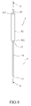
Figure 1 , which shows a perspective view of a transmission line loaded dual-band monopole antenna constructed in accordance with a first embodiment of the present invention, the transmission line loaded dual-band monopole antenna of the present invention is operative in dual bands and is constructed as a monopole antenna added with a transmission line loaded antenna (TLLA) that is loaded with a transmission line. The transmission line that provides the load can be made up of, for example a coaxial cable, parallel conductors, a flexible metal tube or a spiral tube body, and can be positioned at a tail end of the antenna or at a location adjacent to a signal feeding terminal. - The spatial relationship between the transmission line load and the antenna itself is arranged as shown in
Figure 1 , and can also be referred to inFigure 2 , which is a cross-sectional view taken along line 2-2 ofFigure 1 . Themonopole antenna 1 comprises anantenna body 11, asignal feeding terminal 12, and aload connection terminal 13. - An end of the
antenna body 11 forms thesignal feeding terminal 12, and an opposite end forms theload connection terminal 13 and is connected to atransmission line load 2 that serves a load of the antenna. Thetransmission line load 2 of the present invention is arranged at a distant location with respect to the signal feeding terminal. - As shown in
Figure 2 , thetransmission line load 2 comprises acore transmission line 21, an outercircumferential conductor 22, adielectric layer 23, and a short-circuit section 24. Thecore transmission line 21, which serves as a core conductor, is made of for example copper parts, copper-plated aluminum parts, or copper-plated steel parts and has anantenna connection terminal 211 and a short-circuit terminal 212. Theantenna connection terminal 211 is connected to theload connection terminal 13 of themonopole antenna 1. - The outer
circumferential conductor 22 comprises a circumferentially-extending outer conductor ring that is arranged to circumferentially surround and spaced from thecore transmission line 21 by a given distance, and can be constituted by a screen shield or sheath of a coaxial cable. The outercircumferential conductor 22 has anopen terminal 221 and a short-circuit terminal 222 . Theopen terminal 221 of the outercircumferential conductor 22 is close to themonopole antenna 1 so that the outercircumferential conductor 22 forms an open structure facing themonopole antenna 1. The short-circuit terminal 222 is connected to the short-circuit terminal 212 of thecore transmission line 21. - The
dielectric layer 23 is interposed between thecore transmission line 21 and the outercircumferential conductor 22. Thedielectric layer 23 can be for example air dielectric or made up of a non-conductive, insulation dielectric material, such as foamed polyethylene. The short-circuit section 24 is extended from the short-circuit terminal 212 of thecore transmission line 21 to provide the short-circuit terminal 212 of thecore transmission line 21 with a short-circuiting structure. - It is known that adding a capacitive or inductive load allows for control of the high-order second resonant frequency. The present invention is made to resemble the effect by providing a monopole antenna that is loaded by a transmission line structure that serves as a
transmission line load 2. - The
transmission line load 2 itself can serve as a short-circuited transmission line. When the length of thetransmission line load 2 is substantially identical to a quarter of the wavelength of the second resonant frequency, it can serve as an inductive load connected in series to themonopole antenna 1. - For a monopole antenna, the inductive load can affect the high frequency of the second resonance. Thus, the second resonant frequency can be controlled by properly adjusting the length of the
transmission line load 2 to eventually provide themonopole antenna 1 with the operability in dual bands. - To demonstrate that the externally added
transmission line load 2 can be used to control and adjust the resonant frequency, various parameters are used to observe the frequency response of the antenna. Firstly, the length of theantenna body 11 of themonopole antenna 1 is set as "monopole antenna length LR", the length between the short-circuit terminal 222 of the outercircumferential conductor 22 of thetransmission line load 2 and theopen terminal 221 of the outercircumferential conductor 22 is "short-circuit transmission line length LT", and the length of the short-circuit section 24 of thetransmission line load 2 is "extension section length LE". The overall length LA of the transmission line loaded dual-band monopole antenna of the present invention is thus the sum of the monopole antenna length LR plus the short-circuit transmission line length LT and the extension section length LE. - If the short-circuit transmission line length LT of the
transmission line load 2 is set to be the equivalent quarter of the wavelength of a desired second resonant frequency, and the monopole antenna length LR is also set to be the equivalent quarter of the wavelength of the desired second resonant frequency, then due to the short-circuit transmission line forming an RF choke at the second resonant frequency, the second resonant frequency is determined by the monopole antenna length LR. Thus, the monopole antenna length LR can set the second resonance at a given frequency, while the first resonant frequency, which is low frequency, is determined by the overall length LA and can be adjusted using the extension section length LE. -
Figure 3 shows voltage standing wave ratio curves obtained by varying a parameter representing the transmission load length. Under the condition that the overall length LA and the monopole antenna length LR are both fixed, the influence on the frequency response is observed by varying the parameter of the short-circuit transmission line length LT to for example 24mm, 27mm, and 30mm. - To keep the overall length LA and the monopole antenna length LR fixed, the extension section length LE varies in accordance with the variation of the short-circuit transmission line length LT. It is observed from the curves that the high-frequency resonant frequency can be controlled by the short-circuit transmission line length LT solely but the low-frequency resonant frequency is not affected by the variation of the short-circuit transmission line length LT.
-
Figure 4 shows voltage standing wave ratio curves obtained by varying the parameter representing the overall length of the combined transmission line load and the monopole antenna. Under the condition that the short-circuit transmission line length LT and the monopole antenna length LR are fixed, observation on the influence of the frequency response caused by only varying the overall length LA is carried out. - With the short-circuit transmission line length LT and the monopole antenna length LR being not altered, in order to change the overall length LA, the desired factor for changing the overall length LA is the extension section length LE, which is respectively set to 0mm, 2.5mm, and 5mm. It is observed from the curves that the low-frequency resonant frequency can be controlled by the extension section length LE or the overall length LA solely, but the high-frequency resonant frequency is not affected.
-
Figure 5 shows voltage standing wave ratio curves obtained by varying the parameter representing the monopole antenna length. Under the condition that the short-circuit transmission line length LT is fixed, observation of the influence of the frequency response by only varying the monopole antenna length LR is made. - Changing the parameter representing the monopole antenna length LR to for example 40mm, 44mm, and 48mm causes the overall length LA to change accordingly. It is observed from the curves that both low-frequency and high-frequency resonant frequencies are shifted together and this can be used to make desired shifting of the overall frequency for the transmission line loaded dual-band monopole antenna in accordance with the present invention.
- It reveals from the above discussed experimental data that the transmission line loaded dual-band monopole antenna features high precision control of frequency realized by the independent adjustability of the high frequency and low frequency of the dual bands thereof and the simultaneous shifting of both the high and low frequencies.
-
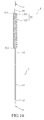
Figure 6 shows a perspective view of a transmission line loaded dual-band monopole antenna constructed in accordance with a second embodiment of the present invention, which is also shown inFigure 7 , which is a cross-sectional view taken along line 7-7 ofFigure 6 . - An end of an
antenna body 11 forms asignal feeding terminal 12, and an opposite end forms aload connection terminal 13 and is connected to a parallel-conductor transmission line that replaces the coaxial cable transmission line of the first embodiment. - The parallel-conductor
transmission line load 3 comprises acore transmission line 31, acarrier ring 32, asupport ring 33, and a pair of parallel and spacedconductors core transmission line 31, which serves as a core conductor, has anantenna connection terminal 311 and a short-circuit terminal 312. Theantenna connection terminal 311 is connected to aload connection terminal 13 of amonopole antenna 1. - The
carrier ring 32 and thesupport ring 33 are respectively arranged on upper and lower ends of thecore transmission line 31 and are spaced from thecore transmission line 31 by a given distance. Thecarrier ring 32 is set at theantenna connection terminal 311 of thecore transmission line 31 and forms anopen terminal 321. Thesupport ring 33 is set close to the short-circuit terminal 312 of thecore transmission line 31. Thecarrier ring 32 and thesupport ring 33 are connected to each other by the pair ofparallel conductors conductors core transmission line 31 by a given distance by for example air dielectric or a non-conductive, insulation dielectric material, such as foamed polyethylene. Thecore transmission line 31 extends beyond the top of the support ring 332 to form a short-circuit section 35. - The outer
circumferential conductor 22 of thetransmission line load 2 in the first embodiment is now replaced by twoopposite conductors -
Figure 8 shows a perspective view of a transmission line loaded dual-band monopole antenna constructed in accordance with a third embodiment of the present invention, which is also shown inFigure 9 , which is a cross-sectional view taken along line 9-9 ofFigure 8 . - A
monopole antenna 1 has anantenna body 11 having an end that forms asignal feeding terminal 12, and an opposite end forming aload connection terminal 13 connected to atransmission line load 4. - The
transmission line load 4 comprises acore transmission line 41, an outercircumferential conductor 42, adielectric layer 43, and a short-circuit section 44. Thecore transmission line 41 has anantenna connection terminal 411 that is connected to theload connection terminal 13 and a short-circuit terminal 412. - The outer
circumferential conductor 42 comprises a circumferentially-extending outer conductor ring that circumferentially surrounds and is spaced from thecore transmission line 41 by a given distance, and is formed by a flexible metal tube. The outercircumferential conductor 42 has anopen terminal 421 and a short-circuit terminal 422. Theopen terminal 421 of the outercircumferential conductor 42 is close to themonopole antenna 1 so that the outercircumferential conductor 42 forms an open structure facing themonopole antenna 1. - The
dielectric layer 43 is interposed between thecore transmission line 41 and the outercircumferential conductor 42. The short-circuit section 44 is connected between the short-circuit terminal 412 of thecore transmission line 41 and the short-circuit terminal 422 of the outercircumferential conductor 42. -
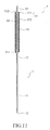
Figure 10 shows a perspective view of a transmission line loaded dual-band monopole antenna constructed in accordance with a fourth embodiment of the present invention, which is also shown inFigure 11 , which is a cross-sectional view taken along line 11-11 ofFigure 10 . - A
monopole antenna 1 comprisesantenna body 11 having an end that forms asignal feeding terminal 12, and an opposite end forming aload connection terminal 13 connected to atransmission line load 5. - The
transmission line load 5 comprises acore transmission line 51, an outercircumferential conductor 52, adielectric layer 53, and a short-circuit section 54. Thecore transmission line 51 has anantenna connection terminal 511 that is connected to theload connection terminal 13 and a short-circuit terminal 512. - The outer
circumferential conductor 52 comprises a circumferentially-extending outer conductor ring that circumferentially surrounds and is spaced from thecore transmission line 51 by a given distance, and is formed by asupport ring 521 and aspiral tube body 522 that is comprised of a plurality of tightly-engaging turns with zero spacing therebetween. Thespiral tube body 522 has an end connected to theclosed support ring 521 and forms an open structure close to theload connection terminal 13 of themonopole antenna 1. - The
dielectric layer 53 is interposed between thecore transmission line 51 and the outercircumferential conductor 52. The short-circuit section 54 is connected between the short-circuit terminal 512 of thecore transmission line 51 and thesupport ring 521 of the outercircumferential conductor 52. -
Figure 12 shows a transmission line loaded dual-band monopole antenna constructed in accordance with a fifth embodiment of the present invention, wherein thetransmission line load 2 is folded to shorten an appearance length of the transmission line without affecting the length of the transmission path. Thetransmission line load 2 ofFigure 12 comprises a coaxial cable transmission line, which is bent and folded to shorten the appearance length of the transmission line. -
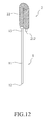
Figure 13 shows a transmission line loaded dual-band monopole antenna constructed in accordance with a sixth embodiment of the present invention andFigures 14 ,15 and16 show variation embodiments of an outer conductor of the antenna ofFigure 13 . - With simultaneous reference to
Figures 13 and14 , thetransmission line load 2 comprises acore transmission line 21 having anantenna connection terminal 211 that is connected to aload connection terminal 13 of an monopole antenna 1a and a short-circuit terminal 212. - The
core transmission line 21 is circumferentially surrounded by an outercircumferential conductor 22 that has anopen terminal 221 forming an open structure with the opening facing the monopole antenna 1a and an opposite terminal that is closed and forms a short-circuit terminal 222. - A
dielectric layer 23 is interposed between thecore transmission line 21 and the outercircumferential conductor 22. The short-circuit section 24 is connected between the short-circuit terminal 212 of thecore transmission line 21 and the short-circuit terminal 222 of the outercircumferential conductor 22. - As shown in
Figure 14 , the monopole antenna 1a is further surrounded by anouter conductor 14 in the form of a coaxial cable in the portion adjacent to asignal feeding terminal 12. Both ends of theouter conductor 14 form closedterminals circumferential conductor 22 that has an open structure formed by anopen terminal 221. Adielectric layer 143 is interposed between anantenna body 11 of the monopole antenna 1a and theouter conductor 14. - The
outer conductor 14 added to the monopole antenna 1a provides theantenna body 11 with a section having a relatively large diameter to realize a great bandwidth. - As shown in
Figure 15 , the monopole antenna 1a is alternatively surrounded by an outer circumferencetubular body 15 having opposite ends that are closedterminals dielectric layer 153 is interposed between theantenna body 11 of the monopole antenna 1a and the outer circumferencetubular body 15. - The outer circumference
tubular body 15 added to the monopole antenna 1a provides a section of relatively large diameter to realize a great bandwidth. - As shown in
Figure 16 , the monopole antenna 1a is alternatively surrounded by anouter spiral body 16 having opposite ends that are closed and form support rings 161, 162. Adielectric layer 163 is interposed between anantenna body 11 of the monopole antenna 1a and theouter spiral body 16. - The
outer spiral body 16 added to the monopole antenna 1a provides theantenna body 11 with a section having a relatively large diameter to realize a great bandwidth. -
Figure 17 shows a perspective view of a transmission line loaded dual-band monopole antenna constructed in accordance with a seventh embodiment of the present invention. Anenclosure 6 of an electronic device has a surface forming in a suitable location anantenna mounting hole 61. Thesignal feeding terminal 12 of the monopole antenna 1a is mounted to the surface of theenclosure 6 through theantenna mounting hole 61 defined in the surface of theenclosure 6. - The
signal feeding terminal 12 of the monopole antenna 1a that extends through theantenna mounting hole 61 defined in the surface of theenclosure 6 is set in connection with acircuit board 62 that mates the monopole antenna 1a. Thecircuit board 62 is arranged at an end of theenclosure 6. Ahot wire 631 of an end of a feedingsignal transmission path 63 is connected to thesignal feeding terminal 12 of the monopole antenna 1a and an opposite end serves as a grounding wire connected to the enclosure to thereby make the enclosure 6 a portion of the monopole antenna 1a. - Although the present invention has been described with reference to the preferred embodiments thereof, it is apparent to those skilled in the art that a variety of modifications and changes may be made without departing from the scope of the present invention which is intended to be defined by the appended claims.
Claims (16)
- A dual-band monopole antenna comprising:a monopole antenna (1, 1 a) having a signal feeding terminal (12) and a load connection terminal (13); anda transmission line load (2, 3, 4, 5) comprising:a core transmission line (21, 31, 41, 51) having an antenna connection terminal (211, 311, 411, 511) and a short-circuit terminal (212, 312, 412, 512), the antenna connection terminal (211, 311, 411, 511) being in connection with the load connection terminal (13) of the monopole antenna (1, 1a);an outer circumferential conductor (22, 341, 342, 42, 52) circumferentially surrounding and spaced from the core transmission line (21, 31, 41, 51), the outer circumferential conductor (22, 341, 342, 42, 52) having an open terminal (221, 321, 421) and a short-circuit terminal (222, 33, 422, 521) opposite to the open terminal (221, 321, 421), the short-circuit terminal (222, 33, 422, 521) being connected to the short-circuit terminal (212, 312, 412, 512) of the core transmission line (21, 31, 41, 51), so that the outer circumferential conductor (22, 341, 342, 42, 52) forms an open structure facing the monopole antenna (1, 1a); anda short-circuit section (24, 35, 44, 54) extended from the short-circuit terminal (212, 312, 412, 512) of the core transmission line (21, 31, 41, 51) to provide the short-circuit terminal (212, 312, 412, 512) of the core transmission line (21, 31, 41, 51) with a short-circuiting structure.
- The dual-band monopole antenna as claimed in Claim 1 further comprisinga dielectric layer (23) interposed between the core transmission line (21, 31, 41, 51) and the outer circumferential conductor (22, 341, 342, 42, 52).
- The dual-band monopole antenna as claimed in Claim 2, characterized in that the dielectric layer (23) comprises dielectric selected from a group consisting of air and an insulation material of foamed polyethylene.
- The dual-band monopole antenna as claimed in Claim 1, characterized in that the transmission line load (2) comprises a transmission line formed by a length of coaxial cable and characterized in that the outer circumferential conductor (22) is formed by a screen shield of the coaxial cable.
- The dual-band monopole antenna as claimed in Claim 1, characterized in that the outer circumferential conductor comprises at least two parallel and spaced conductors (341, 342).
- The dual-band monopole antenna as claimed in Claim 1, characterized in that the outer circumferential conductor comprises an outer spiral tube body (522).
- The dual-band monopole antenna as claimed in Claim 1, characterized in that the outer circumferential conductor comprises a flexible metal tube (42).
- The dual-band monopole antenna as claimed in Claim 1, characterized in that the transmission line load (2) comprises an inductive load connected in series with the monopole antenna (1, 1a).
- The dual-band monopole antenna as claimed in Claim 1, characterized in that a length from the short-circuit terminal (212, 312, 412, 512) of the core transmission line (21, 31, 41, 51) to the open terminal (221, 321, 421) of the outer circumferential conductor (22, 341, 342, 42, 52) forms a short-circuit transmission line length, the short-circuit transmission line length corresponding to an equivalent quarter of a wavelength of a predetermined second resonant frequency, a combined overall length of the monopole antenna (1, 1a) and the transmission line load (2, 3, 4, 5) being set corresponding to an equivalent quarter of a wavelength of a predetermined first resonant frequency.
- The dual-band monopole antenna as claimed in Claim 9, characterized in that the first resonant frequency is determined by a length of the short-circuit section (24, 35, 44, 54) that is connected to the short-circuit terminal (212, 312, 412, 512) of the core transmission line (21, 31, 41, 51).
- The dual-band monopole antenna as claimed in Claim 1 further comprising an outer conductor (14) having a relatively large diameter arranged on a section close to the signal feeding terminal (12) of the monopole antenna (1a).
- The dual-band monopole antenna as claimed in Claim 1 further comprising an outer circumference tubular body (15) having a relatively large diameter arranged on a section close to the signal feeding terminal (12) of the monopole antenna (1a).
- The dual-band monopole antenna as claimed in Claim 1 further comprising an outer spiral body (16) having a relatively large diameter arranged on a section close to the signal feeding terminal (12) of the monopole antenna (1a).
- The dual-band monopole antenna as claimed in Claim 1, characterized in that the signal feeding terminal (12) of the monopole antenna (1a) is connected to a mating circuit board (62) via a feeding signal transmission path (63), and is mounted at an enclosure (6).
- The dual-band monopole antenna as claimed in Claim 14, characterized in that the feeding signal transmission path (63) has an end forming a signal end connected to the monopole antenna (1a) and the enclosure (6) serving as a grounding point for the antenna.
- The dual-band monopole antenna as claimed in Claim 1, characterized in that the transmission line load (2) is folded sideways to shorten length of the transmission line load (2).
Applications Claiming Priority (2)
| Application Number | Priority Date | Filing Date | Title |
|---|---|---|---|
| TW96141724 | 2007-11-05 | ||
| TW097107522A TW200921996A (en) | 2007-11-05 | 2008-03-04 | Transmission line loaded dual-band monopole antenna |
Publications (1)
| Publication Number | Publication Date |
|---|---|
| EP2056401A1 true EP2056401A1 (en) | 2009-05-06 |
Family
ID=39683794
Family Applications (1)
| Application Number | Title | Priority Date | Filing Date |
|---|---|---|---|
| EP08011129A Ceased EP2056401A1 (en) | 2007-11-05 | 2008-06-19 | Transmission line loaded dual-band monopole antenna |
Country Status (3)
| Country | Link |
|---|---|
| US (1) | US7804459B2 (en) |
| EP (1) | EP2056401A1 (en) |
| TW (1) | TW200921996A (en) |
Cited By (1)
| Publication number | Priority date | Publication date | Assignee | Title |
|---|---|---|---|---|
| EP3922099A1 (en) | 2020-06-09 | 2021-12-15 | Carbon BEE | Device for controlling a hydraulic circuit of an agricultural machine for dispensing a liquid product for spraying |
Citations (5)
| Publication number | Priority date | Publication date | Assignee | Title |
|---|---|---|---|---|
| WO1989002662A1 (en) * | 1987-09-09 | 1989-03-23 | Phasar Corporation | Microwave circuit module, such as an antenna, and method of making same |
| DE3732994A1 (en) * | 1987-09-30 | 1989-04-13 | Victor Menzlewski | Multiple antenna combination for the 23cm/70cm/2m and 6m VHF/UHF bands, having a central supply point (feed point) |
| WO1996002075A1 (en) * | 1994-07-08 | 1996-01-25 | R.A. Miller Industries, Inc. | Combined am/fm/cellular telephone antenna system |
| WO1998015031A1 (en) * | 1996-10-02 | 1998-04-09 | Northern Telecom Limited | A multi resonant radio antenna |
| US6266026B1 (en) * | 1998-07-31 | 2001-07-24 | Sti-Co Industries, Inc. | Multiple band antenna |
Family Cites Families (3)
| Publication number | Priority date | Publication date | Assignee | Title |
|---|---|---|---|---|
| US3508271A (en) * | 1966-10-24 | 1970-04-21 | Gen Dynamics Corp | Folded monopole antenna |
| US5995065A (en) * | 1997-09-24 | 1999-11-30 | Nortel Networks Corporation | Dual radio antenna |
| US7388550B2 (en) * | 2005-10-11 | 2008-06-17 | Tdk Corporation | PxM antenna with improved radiation characteristics over a broad frequency range |
-
2008
- 2008-03-04 TW TW097107522A patent/TW200921996A/en unknown
- 2008-06-19 EP EP08011129A patent/EP2056401A1/en not_active Ceased
- 2008-06-23 US US12/213,611 patent/US7804459B2/en active Active
Patent Citations (5)
| Publication number | Priority date | Publication date | Assignee | Title |
|---|---|---|---|---|
| WO1989002662A1 (en) * | 1987-09-09 | 1989-03-23 | Phasar Corporation | Microwave circuit module, such as an antenna, and method of making same |
| DE3732994A1 (en) * | 1987-09-30 | 1989-04-13 | Victor Menzlewski | Multiple antenna combination for the 23cm/70cm/2m and 6m VHF/UHF bands, having a central supply point (feed point) |
| WO1996002075A1 (en) * | 1994-07-08 | 1996-01-25 | R.A. Miller Industries, Inc. | Combined am/fm/cellular telephone antenna system |
| WO1998015031A1 (en) * | 1996-10-02 | 1998-04-09 | Northern Telecom Limited | A multi resonant radio antenna |
| US6266026B1 (en) * | 1998-07-31 | 2001-07-24 | Sti-Co Industries, Inc. | Multiple band antenna |
Non-Patent Citations (2)
| Title |
|---|
| KENNEDY T F ET AL: "Investigation of impedance and radiation properties of dual-frequency choke-loaded monopole antennas", ELECTRONICS LETTERS, IEE STEVENAGE, GB, vol. 39, no. 6, 20 March 2003 (2003-03-20), pages 490 - 491, XP006020082, ISSN: 0013-5194 * |
| SHAWN D ROGERS ET AL: "Wide-band Sleeve-Cage and Sleeve-Helical Antennas", IEEE TRANSACTIONS ON ANTENNAS AND PROPAGATION, IEEE SERVICE CENTER, PISCATAWAY, NJ, US, vol. 50, no. 10, 1 October 2002 (2002-10-01), XP011068629, ISSN: 0018-926X * |
Cited By (1)
| Publication number | Priority date | Publication date | Assignee | Title |
|---|---|---|---|---|
| EP3922099A1 (en) | 2020-06-09 | 2021-12-15 | Carbon BEE | Device for controlling a hydraulic circuit of an agricultural machine for dispensing a liquid product for spraying |
Also Published As
| Publication number | Publication date |
|---|---|
| TWI343146B (en) | 2011-06-01 |
| US7804459B2 (en) | 2010-09-28 |
| US20090115678A1 (en) | 2009-05-07 |
| TW200921996A (en) | 2009-05-16 |
Similar Documents
| Publication | Publication Date | Title |
|---|---|---|
| CN100514869C (en) | Apparatus for reducing ground effects in a folder-type communications handset device | |
| EP2154752B1 (en) | Multi-band ceiling antenna | |
| US6674405B2 (en) | Dual-band meandering-line antenna | |
| US8941548B2 (en) | Antenna device and electronic apparatus including antenna device | |
| US7170456B2 (en) | Dielectric chip antenna structure | |
| CN102396109B (en) | Multi-band dipole antennas | |
| US7064728B1 (en) | Ultra-wideband dipole antenna | |
| US20060284770A1 (en) | Compact dual band antenna having common elements and common feed | |
| JP2002512463A (en) | Ground extension structure for coupling to ground means of antenna system, antenna system, and mobile communication device having the ground structure | |
| KR20120054084A (en) | High isolation antenna system | |
| US7230573B2 (en) | Dual-band antenna with an impedance transformer | |
| JP2000223928A (en) | Antenna system | |
| CN105917527A (en) | Multi-band antenna and communication terminal | |
| JP2000509926A (en) | Antenna device having matching means | |
| EP1942556A1 (en) | Antenna and electronic equipment having the same | |
| GB2430307A (en) | Compact balanced antenna arrangement | |
| US8013799B2 (en) | Dual-band monopole antenna with antenna signal fed through short-circuit terminal of transmission line | |
| US20170194694A1 (en) | Dual-band wi-fi antenna and mobile terminal | |
| US8063847B2 (en) | Multi-band antenna | |
| US20150009093A1 (en) | Antenna apparatus and portable wireless device equipped with the same | |
| US7804459B2 (en) | Transmission line loaded dual-band monopole antenna | |
| KR20040010556A (en) | Minimum frequency shift telescoping antenna | |
| EP1892798A1 (en) | Folded planar monopole antenna | |
| US20080300029A1 (en) | Inductive flexible circuit for communication device | |
| WO2019150874A1 (en) | Antenna device |
Legal Events
| Date | Code | Title | Description |
|---|---|---|---|
| PUAI | Public reference made under article 153(3) epc to a published international application that has entered the european phase |
Free format text: ORIGINAL CODE: 0009012 |
|
| 17P | Request for examination filed |
Effective date: 20090216 |
|
| AK | Designated contracting states |
Kind code of ref document: A1 Designated state(s): AT BE BG CH CY CZ DE DK EE ES FI FR GB GR HR HU IE IS IT LI LT LU LV MC MT NL NO PL PT RO SE SI SK TR |
|
| AX | Request for extension of the european patent |
Extension state: AL BA MK RS |
|
| RAP1 | Party data changed (applicant data changed or rights of an application transferred) |
Owner name: GETAC TECHNOLOGY CORPORATION |
|
| 17Q | First examination report despatched |
Effective date: 20091027 |
|
| AKX | Designation fees paid |
Designated state(s): DE FR GB NL |
|
| RBV | Designated contracting states (corrected) |
Designated state(s): DE FR GB NL |
|
| STAA | Information on the status of an ep patent application or granted ep patent |
Free format text: STATUS: THE APPLICATION HAS BEEN REFUSED |
|
| 18R | Application refused |
Effective date: 20150521 |