EP2065732A2 - Optical sensor and method for determining the position of objects - Google Patents
Optical sensor and method for determining the position of objects Download PDFInfo
- Publication number
- EP2065732A2 EP2065732A2 EP08019966A EP08019966A EP2065732A2 EP 2065732 A2 EP2065732 A2 EP 2065732A2 EP 08019966 A EP08019966 A EP 08019966A EP 08019966 A EP08019966 A EP 08019966A EP 2065732 A2 EP2065732 A2 EP 2065732A2
- Authority
- EP
- European Patent Office
- Prior art keywords
- light
- optical sensor
- detector
- detected
- transmitters
- Prior art date
- Legal status (The legal status is an assumption and is not a legal conclusion. Google has not performed a legal analysis and makes no representation as to the accuracy of the status listed.)
- Withdrawn
Links
Images


Classifications
-
- G—PHYSICS
- G01—MEASURING; TESTING
- G01V—GEOPHYSICS; GRAVITATIONAL MEASUREMENTS; DETECTING MASSES OR OBJECTS; TAGS
- G01V8/00—Prospecting or detecting by optical means
- G01V8/10—Detecting, e.g. by using light barriers
- G01V8/20—Detecting, e.g. by using light barriers using multiple transmitters or receivers
-
- G—PHYSICS
- G01—MEASURING; TESTING
- G01S—RADIO DIRECTION-FINDING; RADIO NAVIGATION; DETERMINING DISTANCE OR VELOCITY BY USE OF RADIO WAVES; LOCATING OR PRESENCE-DETECTING BY USE OF THE REFLECTION OR RERADIATION OF RADIO WAVES; ANALOGOUS ARRANGEMENTS USING OTHER WAVES
- G01S17/00—Systems using the reflection or reradiation of electromagnetic waves other than radio waves, e.g. lidar systems
- G01S17/02—Systems using the reflection of electromagnetic waves other than radio waves
- G01S17/06—Systems determining position data of a target
-
- G—PHYSICS
- G01—MEASURING; TESTING
- G01S—RADIO DIRECTION-FINDING; RADIO NAVIGATION; DETERMINING DISTANCE OR VELOCITY BY USE OF RADIO WAVES; LOCATING OR PRESENCE-DETECTING BY USE OF THE REFLECTION OR RERADIATION OF RADIO WAVES; ANALOGOUS ARRANGEMENTS USING OTHER WAVES
- G01S7/00—Details of systems according to groups G01S13/00, G01S15/00, G01S17/00
- G01S7/48—Details of systems according to groups G01S13/00, G01S15/00, G01S17/00 of systems according to group G01S17/00
- G01S7/481—Constructional features, e.g. arrangements of optical elements
- G01S7/4814—Constructional features, e.g. arrangements of optical elements of transmitters alone
-
- G—PHYSICS
- G01—MEASURING; TESTING
- G01S—RADIO DIRECTION-FINDING; RADIO NAVIGATION; DETERMINING DISTANCE OR VELOCITY BY USE OF RADIO WAVES; LOCATING OR PRESENCE-DETECTING BY USE OF THE REFLECTION OR RERADIATION OF RADIO WAVES; ANALOGOUS ARRANGEMENTS USING OTHER WAVES
- G01S7/00—Details of systems according to groups G01S13/00, G01S15/00, G01S17/00
- G01S7/48—Details of systems according to groups G01S13/00, G01S15/00, G01S17/00 of systems according to group G01S17/00
- G01S7/497—Means for monitoring or calibrating
Abstract
Description
Die vorliegende Erfindung bezieht sich in einem ersten Aspekt auf einen optischen Sensor zur Positionsbestimmung von Objekten in einem Überwachungsbereich nach dem Oberbegriff des Anspruchs 1.The present invention relates in a first aspect to an optical sensor for determining the position of objects in a surveillance area according to the preamble of claim 1.
In einem zweiten Gesichtspunkt betrifft die Erfindung ein Verfahren zur Positionsbestimmung von Objekten in einem Überwachungsbereich nach dem Oberbegriff des Anspruchs 9.In a second aspect, the invention relates to a method for determining the position of objects in a surveillance area according to the preamble of claim 9.
Ein gattungsgemäßer optischer Sensor und ein gattungsgemäßes Verfahren sind beispielsweise aus
Ein optischer Sensor der genannten Art weist eine Mehrzahl von Lichtsendern zum Aussenden von Licht auf, wobei jedem Lichtsender ein Überwachungsteilbereich zugeordnet ist, in welchen der jeweilige Lichtsender Lichtsignale aussendet. Außerdem ist eine Ansteuereinheit zum Ansteuern der Lichtsender vorgesehen.An optical sensor of the type mentioned has a plurality of light emitters for emitting light, wherein each light emitter is associated with a monitoring portion, in which the respective light emitter emits light signals. In addition, a drive unit for driving the light emitter is provided.
Bei einem Verfahren der genannten Art sendet eine Mehrzahl von Lichtsendern Licht in Überwachungsteilbereiche aus, die den Lichtsendern jeweils zugeordnet sind.In a method of the type mentioned, a plurality of light emitters emit light in monitoring subregions which are respectively assigned to the light emitters.
Bei konventionellen Reflexionslichtschranken sendet ein Lichtsender Licht aus und dieses wird von Objekten in einem Überwachungsbereich und/oder von einem Reflektor zurückgestreut oder zurückgestrahlt und sodann in einem Empfänger nachgewiesen. Das Licht kann beispielsweise vom Sender durch einen halbdurchlässigen Spiegel und eine Linse zum Retroreflektor gelangen, wird dann vom Retroreflektor zur Linse zurückreflektiert und anschließend von dem halbdurchlässigen Spiegel zu einem Empfänger reflektiert. Bei Überschreiten eines Entscheidungsschwellwerts der auf den Empfänger auftreffenden Lichtleistung schaltet die Lichtschranke aus, da der Lichtweg zwischen der Lichtschranke und dem Retroreflektor frei ist.In conventional reflection light barriers, a light emitter emits light and this is backscattered or reflected by objects in a surveillance area and / or by a reflector and then detected in a receiver. For example, the light may pass from the transmitter to the retroreflector through a semitransparent mirror and lens, is then reflected back to the lens by the retroreflector and then reflected by the semitransparent mirror to a receiver. If a decision threshold is exceeded on the receiver incident light power turns off the photocell because the light path between the photocell and the retroreflector is free.
Wenn sich ein diffus reflektierendes Objekt zwischen Sensor und Retroreflektor befindet, trifft der Lichtstrahl nicht auf den Retroreflektor. Der Retroreflektor reflektiert das Licht gerichtet zurück, wogegen ein diffus reflektierendes Objekt das Licht vergleichsweise breit streut und nur einen geringen Anteil des Lichts in Richtung des Sensors zurück reflektiert. Daraus erfolgt, dass die am Empfänger ankommende Lichtleistung geringer ist, als wenn das Licht vom Reflektor reflektiert wird. Entsprechend wird der Entscheidungsschwellwert unterschritten und der Sensor schaltet ein.If there is a diffuse reflective object between the sensor and the retroreflector, the light beam will not hit the retroreflector. The retroreflector reflects the light back, whereas a diffusely reflecting object diffuses the light comparatively wide and reflects only a small portion of the light back towards the sensor. It follows that the light output arriving at the receiver is lower than when the light is reflected by the reflector. Accordingly, the decision threshold is exceeded and the sensor turns on.
Wenn größere Raumbereiche überwacht werden sollen, können auch mehrere Lichtschranken parallel eingesetzt werden. Man spricht dann auch von Lichtvorhängen oder Lichtgittern. Ein solches Lichtgitter ist beispielsweise in
Zum Nachweis des auf die einzelnen Lichtquellen zurückgehenden gestreuten und/oder reflektierten Lichts ist bei der Anordnung von
Weitere optische Sensoren, bei denen mehrere Lichtsender eingesetzt werden, sind in
Aufgabe der Erfindung ist, einen optischen Sensor zur Positionsbestimmung von Objekten in einem Überwachungsbereich zu schaffen, der besonders einfach und kompakt aufgebaut ist und gleichwohl eine hohe Funktionalität aufweist. Außerdem soll ein Verfahren zur Positionsbestimmung von Objekten in einem Überwachungsbereich angegeben werden, welches besonders vielseitig einsetzbar ist. The object of the invention is to provide an optical sensor for determining the position of objects in a surveillance area, which is constructed particularly simple and compact and nevertheless has a high functionality. In addition, a method for determining the position of objects in a surveillance area is to be specified, which is particularly versatile.
Diese Aufgabe wird in einem ersten Gesichtpunkt gelöst durch den optischen Sensor mit den Merkmalen des Anspruchs 1.This object is achieved in a first aspect by the optical sensor having the features of claim 1.
In einem zweiten Aspekt wird die Aufgabe gelöst durch das Verfahren mit den Merkmalen des Anspruchs 9.In a second aspect, the object is achieved by the method having the features of claim 9.
Bevorzugte Ausgestaltungen des erfindungsgemäßen optischen Sensors und vorteilhafte Varianten des erfindungsgemäßen Verfahrens sind Gegenstand der nachfolgenden Beschreibung, der Figuren mit zugehöriger Figurenbeschreibung sowie der Unteransprüche.Preferred embodiments of the optical sensor according to the invention and advantageous variants of the method according to the invention are the subject of the following description, the figures with associated description of the figures and the dependent claims.
Der optische Sensor der oben genannten Art ist erfindungsgemäß dadurch weitergebildet, dass zum Nachweis von von einem nachzuweisenden Objekt reflektiertem und/oder gestreutem Licht genau ein gemeinsamer Detektor vorhanden ist, welcher genau ein zeitabhängiges Detektionssignal liefert, dass die Ansteuereinheit zum zeitlich jeweils unterschiedlichen Aktivieren der verschiedenen Lichtsender eingerichtet ist, dass eine mit dem Detektor verbundene Auswerteeinheit vorhanden ist, die mit der Ansteuereinheit zusammenwirkt und zum Auswerten des Detektionssignals sowie zum Zuordnen von einzelnen Anteilen des Detektionssignals zu Lichtsignalen der verschiedenen Lichtsender eingerichtet ist, dass die Auswerteeinheit zum Abspeichern von für das nachzuweisende Objekt spezifischen Vergleichsdaten eingerichtet ist und dass die Auswerteeinheit für das Bestimmen und Ausgeben einer Position des nachzuweisenden Objekts im Überwachungsbereich durch Vergleich der einzelnen Signalanteile mit den Vergleichsdaten eingerichtet ist.According to the invention, the optical sensor of the abovementioned type is further developed in that exactly one common detector is present for the detection of light reflected and / or scattered by an object to be detected, which supplies precisely a time-dependent detection signal, that the activation unit for activating the different Light transmitter is arranged that an evaluation unit connected to the detector is present, which cooperates with the drive unit and for evaluating the detection signal and for assigning individual portions of the detection signal to light signals of the different light emitter is set up, that the evaluation unit for storing the object to be detected is set up specific comparison data and that the evaluation unit for determining and outputting a position of the object to be detected in the monitored area by comparing the individual signal components with the Vergl calibration data is set up.
Das Verfahren der oben genannten Art ist erfindungsgemäß dadurch weitergebildet, dass von dem nachzuweisenden Objekt im Überwachungsbereich und/oder von einem Reflektor reflektiertes und/oder gestreutes Licht mit genau einem gemeinsamen Detektor nachgewiesen wird, dass dem von den verschiedenen Lichtsendern ausgehenden Licht eine jeweils unterschiedliche zeitliche Struktur aufgeprägt wird, dass das Detektorsignal bezüglich der auf die unterschiedlichen Lichtsender zurückgehenden Signalanteile ausgewertet wird, dass für das nachzuweisende Objekt gemessene Normalwerte der gestreuten und/oder reflektierten Lichtintensität als Vergleichsdaten eingelernt werden, dass die auf die unterschiedlichen Lichtsender zurückgehenden Signalanteile des Detektorsignals mit den Vergleichsdaten verglichen werden und dass abhängig vom Resultat dieses Vergleichs eine Position des Objektes bestimmt und ausgegeben wird.The method of the abovementioned type is developed according to the invention by detecting light reflected and / or scattered by the object to be detected in the surveillance area and / or by a reflector with exactly one common detector, that the light emanating from the different light transmitters each have a different temporal Structure is impressed that the detector signal is evaluated with respect to the reverting to the different light emitter signal components, that for the object to be detected normal values of the scattered and / or reflected light intensity are learned as comparison data, that the going back to the different light emitter signal components of the detector signal with the comparison data be compared and that depending on the result of this comparison, a position of the object is determined and output.
Eine wesentliche Erkenntnis der Erfindung besteht darin, dass die Funktionalität mehrerer Detektoren, soweit die entsprechenden Strahlengänge dies ermöglichen, bereits weitgehend durch einen einzigen Detektor realisiert werden können. Hierzu wird den Lichtsignalen der einzelnen Lichtsender eine geeignete zeitliche Struktur aufgeprägt, anhand welcher die auf die entsprechenden Lichtsender zurückgehenden Anteile des Detektorsignals voneinander getrennt werden können. Somit besteht ein erster Kerngedanke der Erfindung darin, im Unterschied zu
Ein weiterer Kerngedanke besteht darin, den Lichtsignalen der einzelnen Lichtsender eine jeweils unterschiedliche Zeitstruktur aufzuprägen, beispielsweise das ausgesendete Licht jeweils unterschiedlich zu modulieren, und das Detektionssignal im Hinblick auf die auf die einzelnen Lichtsender zurückgehenden Anteile auszuwerten.Another core idea is to impose a different time structure on the light signals of the individual light transmitters, for example to differently modulate the emitted light in each case, and to evaluate the detection signal with respect to the components attributable to the individual light transmitters.
Schließlich besteht ein Grundgedanke der Erfindung darin, die von dem nachzuweisenden Objekt normalerweise zurückgestreuten und/oder zurückreflektierten Lichtintensitäten einzulernen, diese eingelernten Daten mit den Messdaten zu vergleichen und abhängig von diesem Vergleich ein Positionssignal zu ermitteln und auszugeben. Hierdurch kann die Präzision bei der Positionsbestimmung deutlich erhöht werden.Finally, it is a basic idea of the invention to teach the light intensities normally backscattered and / or reflected back from the object to be detected, to compare this learned data with the measured data and to determine and output a position signal depending on this comparison. As a result, the precision in determining the position can be significantly increased.
Wegen des Vergleichs der Messdaten mit zuvor eingelernten Vergleichswerten eignen sich der erfindungsgemäße optische Sensor und das erfindungsgemäße Verfahren besonders zum Nachweis und zur Positionsbestimmung von grundsätzlich bekannten Objekten.Because of the comparison of the measured data with previously learned comparison values, the optical sensor according to the invention and the method according to the invention are particularly suitable for detecting and determining the position of fundamentally known objects.
Ein wesentlicher Vorteil des erfindungsgemäßen optischen Sensors und des erfindungsgemäßen Verfahrens besteht darin, dass durch den zusätzlichen Lichtsender eine Vielzahl von neuen Funktionalitäten bereitgestellt werden, die nachstehend im Einzelnen beschrieben werden.An essential advantage of the optical sensor according to the invention and of the method according to the invention is that a large number of new functionalities are provided by the additional light transmitter, which will be described in detail below.
Neben der sehr kompakten Bauform zeichnet sich der erfindungsgemäße optische Sensor insbesondere durch eine einfache Installation aus, da hier nur eine statt zwei oder mehrere Lichtschranken zu montieren ist. Weiterhin werden bei dem erfindungsgemäßen Verfahren und dem erfindungsgemäßen Sensor Schwierigkeiten und Probleme der gegenseitigen Beeinflussung, wie sie bei der Verwendung von mehreren einzelnen Sensoren auftreten, weitestgehend vermieden. Weiterhin lässt sich der erfindungsgemäße Sensor zu deutlich geringeren Kosten fertigen als zwei oder mehrere Sensoren, welche dieselbe Funktionalität liefern würden.In addition to the very compact design, the optical sensor according to the invention is characterized in particular by a simple installation, since only one instead of two or more light barriers is to be mounted here. Furthermore, in the method according to the invention and the sensor according to the invention, difficulties and problems of mutual influence, as they occur when using a plurality of individual sensors, are largely avoided. Furthermore, the inventive Produce sensor at significantly lower cost than two or more sensors that would provide the same functionality.
Ein sehr wichtiger Vorteil der Erfindung ist weiterhin, dass Teile der Auswertung, die bei Einsatz mehrerer konventioneller Sensoren in der Anwendung, also in einer übergeordneten Einrichtung, programmiert sind, bereits vom Sensor selbst vorgenommen werden können.A very important advantage of the invention is further that parts of the evaluation, which are programmed when using a plurality of conventional sensors in the application, ie in a higher-level device, can already be performed by the sensor itself.
Der erfindungsgemäße optische Sensor kann grundsätzlich als Lichttaster eingesetzt werden, das heißt, dass im Wesentlichen das von einem nachzuweisenden Objekt und/oder gegebenenfalls von einer Hintergrundfläche gestreute und/oder reflektierte Licht nachgewiesen wird. Hierbei können auch diffus reflektierende Objekte erkannt werden. Durch Anpassung der Empfindlichkeit des Empfängers kann der erfindungsgemäße optische Sensor auch als Reflexionslichtschranke verwendet werden, das heißt, dass ein Reflektor zum Begrenzen des Überwachungsbereichs vorhanden ist. Ein solcher Reflektor kann im Grundsatz beliebige Formen aufweisen und prinzipiell auch mehrteilig gebildet, also aus einer Mehrzahl von Einzelreflektoren aufgebaut sein.The optical sensor according to the invention can basically be used as a light scanner, that is to say that essentially the light scattered and / or reflected by an object to be detected and / or optionally by a background surface is detected. Here also diffuse reflecting objects can be detected. By adjusting the sensitivity of the receiver, the optical sensor according to the invention can also be used as a reflection light barrier, that is to say that a reflector for limiting the monitoring area is present. Such a reflector may in principle have any shapes and, in principle, also formed in several parts, that is to say constructed from a plurality of individual reflectors.
Als Detektoren können grundsätzlich bekannte Fotodetektoren, vor allem also Halbleiterdetektoren, verwendet werden. Ein wesentlicher erfindungsgemäßer Vorteil ist, dass nur ein einzelner Detektor benötigt wird. Bei einer besonders einfachen Ausgestaltung weist dieser Detektor nur ein einziges Detektorelement auf. Hierdurch wird der Aufbau des Sensors insgesamt wesentlich vereinfacht.Basically known photodetectors, in particular semiconductor detectors, can be used as detectors. An essential advantage of the invention is that only a single detector is needed. In a particularly simple embodiment, this detector has only a single detector element. As a result, the structure of the sensor is greatly simplified overall.
Bei einem besonders bevorzugten Ausführungsbeispiel weist der optische Sensor genau zwei Lichtsender auf. Mit einem solchen Sensor können im Wesentlichen bereits alle nachstehend beschriebenen Funktionalitäten bereitgestellt werden.In a particularly preferred embodiment, the optical sensor has exactly two light transmitters. Essentially, all of the functionalities described below can be provided with such a sensor.
An die Lichtsender ist grundsätzlich keine hohe Anforderung gestellt und es können prinzipiell bekannte Komponenten verwendet werden. Bei einer bevorzugten Ausgestaltung sind die Lichtsender Infrarot-Lichtquellen, insbesondere Infrarot-Laserdioden. Die Ansteuereinheit für die Lichtsender und die Auswerteeinheit für das Detektorsignal können zweckmäßig in einem Mikrocontroller integriert sein.In principle, no high demand is placed on the light transmitters and, in principle, known components can be used. In a preferred embodiment, the light emitters are infrared light sources, in particular infrared laser diodes. The drive unit for the light transmitters and the evaluation unit for the detector signal may be expediently integrated in a microcontroller.
Im Hinblick auf die zeitliche Struktur der Lichtsignale der verschiedenen Lichtsender bestehen zahlreiche Variationsmöglichkeiten. Wichtig ist hierbei, dass die Lichtsignale der einzelnen Lichtsender hinreichend verschieden sind, damit die entsprechenden Anteile des Detektorsignals gut getrennt werden können. Beispielsweise werden die Lichtsender mit jeweils unterschiedlichen Frequenzen moduliert. Bei einer besonders einfachen Variante des erfindungsgemäßen Verfahrens werden die Lichtsender abwechselnd gepulst. Grundsätzlich ist es möglich, dass das Sendelicht und das vom Detektor nachzuweisende Licht mit ein- und derselben Optik sowie einem teildurchlässigen Spiegel in den Überwachungsbereich geleitet und aus dem Überwachungsbereich auf den Detektor geführt wird. Mit einer solchen Autokollimationsoptik können besonders kompakte Anordnungen erreicht werden.With regard to the temporal structure of the light signals of the various light transmitters, there are numerous possible variations. It is important here that the light signals of the individual light emitters are sufficiently different, so that the corresponding proportions of the detector signal can be separated well. For example, the light emitters are modulated with different frequencies. In a particularly simple variant of the method according to the invention, the light emitters are alternately pulsed. In principle, it is possible for the transmitted light and the light to be detected by the detector to be guided into the monitoring area with one and the same optics and a partially transmissive mirror and guided out of the monitoring area onto the detector. With such a autocollimation optics particularly compact arrangements can be achieved.
Bei einer kostengünstigen Variante ist zum Leiten des Lichts der Lichtsender in den Überwachungsbereich eine gemeinsame Sendeoptik vorhanden und zum Leiten des Lichts auf den Detektor ist eine von der Sendeoptik verschiedene Detektoroptik vorhanden.In a cost-effective variant, a common transmitting optics is present for guiding the light of the light emitter in the monitoring area and for guiding the light to the detector is a different from the transmitting optics detector optics available.
Besonders bevorzugt ist weiterhin, wenn die Vergleichsdaten für eine Vielzahl von Positionen des Objekts abgespeichert werden. Der optische Sensor kann dann noch aussagekräftigere Messresultate liefern. Beispielsweise kann in einer einfachen Anwendung für die zu überwachenden Objekte eine Höhenkontrolle durchgeführt werden. Bei einer weiteren Verwendungsvariante, die ebenfalls im industriellen Bereich viele Einsatzmöglichkeiten hat, wird eine Position des Objekts in einer Richtung quer zu einer Erstrekkungsrichtung der Hauptstrahlrichtungen der Lichtsender bestimmt. Schließlich kann grundsätzlich auch eine Bewegungsrichtung und gegebenenfalls auch eine Geschwindigkeit eines zu überwachenden Objekts bestimmt werden.It is furthermore particularly preferred if the comparison data are stored for a multiplicity of positions of the object. The optical sensor can then provide even more meaningful measurement results. For example, a height control can be performed in a simple application for the objects to be monitored. In a further variant of use, which also has many uses in the industrial sector, a position of the object is determined in a direction transverse to a Erstrekkungsrichtung the main beam directions of the light emitter. Finally, in principle, a direction of movement and optionally also a speed of an object to be monitored can be determined.
Bei einer weiteren bevorzugten Variante weist das zu überwachende Objekt eine Streifenstruktur auf, welche so gestaltet ist, dass sie Schaltvorgänge des optischen Sensors auslösen kann, und der optische Sensor wird entsprechend als Inkrementalgeber betrieben. Hierbei kann eine Geschwindigkeits- und/oder Wegbestimmung bereits mit äußerst geringen aparativen Mitteln erzielt werden.In a further preferred variant, the object to be monitored has a strip structure which is designed so that it can trigger switching operations of the optical sensor, and the optical sensor is operated accordingly as an incremental encoder. In this case, a speed and / or travel determination can already be achieved with extremely low practical means.
Besonders vorteilhafte Anwendungen hat das erfindungsgemäße Verfahren für Messsituationen, wo das zu überwachende Objekt eine Kante eines bahnartigen Materials ist und wobei der optische Sensor bezüglich der Kante so positioniert wird, dass mindestens für den Strahlengang eines Lichtsenders ein Teil des Lichts durchgelassen wird und ein weiterer Teil von der Kante abgeblockt wird.The method according to the invention has particularly advantageous applications for measurement situations where the object to be monitored is an edge of a web-like material and wherein the optical sensor is positioned relative to the edge so that at least for the beam path of a light transmitter part of the light is transmitted and another part is blocked by the edge.
Eine solche Bahnkantenerkennung ist mit Hilfe des erfindungsgemäßen optischen Sensors und des erfindungsgemäßen Verfahrens auf sehr einfache und dabei präzise und flexibel möglich. Hierbei werden beide Sensoren ausgewertet. Bei einer ersten Möglichkeit wird hierbei ein Kanal zur Bewertung der Position der Bahnkante verwendet und der andere Kanal wird zur Überwachung und gegebenenfalls zur Nachregelung des ersten Kanals eingesetzt.Such web edge detection is possible with the aid of the optical sensor according to the invention and the method according to the invention in a very simple and precise and flexible. Both sensors are evaluated here. In a first possibility, a channel is used here for evaluating the position of the web edge, and the other channel is used for monitoring and optionally for readjusting the first channel.
Diese Verfahrensvariante ist für alle Einsatzzwecke vorteilhaft, wo ein erster Lichtweg ständig belegt, also nie frei ist, und wo deshalb eine Nachregelung nicht über einen einzigen Kanal erfolgen kann.This variant of the method is advantageous for all applications where a first light path is constantly occupied, that is, never free, and therefore where readjustment can not take place via a single channel.
Die verschiedenen Überwachungsteilbereiche können prinzipiell völlig unterschiedlich sein, also keinerlei Überdeckungen aufweisen. Bei bestimmten bevorzugten Ausgestaltungen werden die Lichtsender jedoch gezielt so angeordnet, dass sich die Überwachungsteilbereiche von mindestens zwei Lichtsender überlappen. Hierdurch wird eine vorteilhafte Verfahrensvariante ermöglicht, bei der mindestens ein Verhältnis von auf verschiedene Lichtsender zurückgehenden Signalanteilen des Detektorsignals gebildet und ausgewertet wird.The different monitoring subregions can in principle be completely different, ie have no overlaps. In certain preferred embodiments, however, the light emitters are specifically arranged so that the monitoring subregions of at least two light emitters overlap. In this way, an advantageous variant of the method is made possible in which at least one ratio of signal components of the detector signal attributable to different light transmitters is formed and evaluated.
Bei dieser Verfahrensvariante werden demnach Verhältnisse von überlappenden Lichtflecken gebildet. Hierbei ist die Optik des Sensors so anzupassen, dass sich die Lichtflecke der mindestens zwei Lichtquellen, beispielsweise auf dem nachzuweisenden Objekt, überlappen. Dieses Prinzip lässt sich sowohl unter Verwendung eines Retroreflektors, als auch im tastenden Betrieb anwenden, wenn die Empfindlichkeit der Auswertung entsprechend erhöht wird.Accordingly, ratios of overlapping light spots are formed in this process variant. Here, the optics of the sensor is to be adapted so that the light spots of the at least two light sources, for example on the object to be detected, overlap. This principle can be applied both by using a retroreflector and during grooving operation, if the sensitivity of the evaluation is correspondingly increased.
Wieder können die beiden Lichtsender abwechselnd gepulst werden, um jeweils das Empfangssignal auswerten zu können. Die Kante eines Objekts, dessen Position auszuwerten ist, muss sich im Überlappungsbereich der beiden Kanäle befinden. Während eines Einlernvorganges ermittelt und speichert der Sensor das Verhältnis der beiden Empfangssignale. Dieses Verhältnis wird wie das oben beschriebene Empfangssignal ausgewertet. Der Vorteil dieser Anordnung besteht darin, dass der Abstand vom Sensor und die Oberflächeneigenschaften des Objekts im Wesentlichen keinen Einfluss auf die Orte der Schaltpunkte haben. Die Optik sollte hierzu so ausgelegt sein, dass der Überlappungsbereich einen parallelen Strahlengang mit konstantem Durchmesser bildet.Again, the two light emitter can be alternately pulsed to evaluate the received signal can. The edge of an object whose position is to be evaluated must be in the overlap area of the two channels. During a teach-in process, the sensor determines and stores the ratio of the two received signals. This ratio is evaluated like the receive signal described above. The advantage of this arrangement is that the distance from the sensor and the surface properties of the object have substantially no influence on the locations of the switching points. The optics should be designed so that the overlap area forms a parallel beam path with a constant diameter.
Weitere Vorteile und Merkmale des erfindungsgemäßen optischen Sensors und des erfindungsgemäßen Verfahrens werden nachstehend mit Bezug auf die beigefügten Figuren in weiteren Details beschrieben.Further advantages and features of the optical sensor according to the invention and of the method according to the invention are described below in further detail with reference to the attached figures.
- Fig. 1Fig. 1
- ein erstes Ausführungsbeispiel eines erfindungsgemäßen optischen Sensors;a first embodiment of an optical sensor according to the invention;
- Fig. 2Fig. 2
-
den optischen Sensor aus
Fig. 1 in einem Anwendungsbeispiel;the optical sensor offFig. 1 in an application example; - Fig. 3Fig. 3
- ein zweites Ausführungsbeispiel eines erfindungsgemäßen optischen Sensors;A second embodiment of an optical sensor according to the invention;
- Fig. 4Fig. 4
- ein weiteres Anwendungsbeispiel eines erfindungsgemäßen optischen Sensors zur Bahnkantenerkennung;Another application example of an optical sensor according to the invention for web edge detection;
- Fig. 5Fig. 5
- ein weiteres Anwendungsbeispiel eines erfindungsgemäßen optischen Sensors zur Bahnkantenerkennung;Another application example of an optical sensor according to the invention for web edge detection;
- Fig. 6Fig. 6
- ein erstes Beispiel für Form und Position von zwei sich überlappenden Lichtflecken; unda first example of the shape and position of two overlapping spots of light; and
- Fig. 7Fig. 7
- ein zweites Beispiel für Form und Position von zwei sich überlappenden Lichtflecken.a second example of the shape and position of two overlapping spots of light.
Ein erstes Ausführungsbeispiel der Erfindung wird mit Bezug auf die
Der in den
Die Überwachungsteilbereiche 92, 94 bilden einen Überwachungsbereich 90, der von einem Retroreflektor 60 begrenzt wird. Im gezeigten Beispiel handelt es sich bei dem optischen Sensor 100 demgemäß um eine Reflexionslichtschranke.The
Die von den Lichtsendern 20,40 ausgesandten Lichtsignale treten zunächst durch einen teildurchlässigen Spiegel 32 und werden sodann von der Autokollimationsoptik 30 entlang der Hauptstrahlrichtungen 29, 49 in den Überwachungsbereich 90 geleitet. Nach Reflexion oder Streuung am Retroreflektor 60 und erneutem Durchtritt durch die jeweiligen Überwachungsteilbereiche 92, 94 tritt das Licht 22, 42 erneut durch die Autokollimationsoptik 30 und wird anschließend mindestens teilweise am teil- oder halbdurchlässigen Spiegel 32 in Richtung des Detektors 50 geleitet und dort quantitativ und zeitaufgelöst nachgewiesen. Das vom Detektor 50 nachzuweisende Licht ist mit dem Bezugszeichen 52 versehen.The light signals emitted by the
Die Lichtsender 20, 40 werden von der Ansteuereinheit 70 angesteuert, wobei den einzelnen Lichtsendern 20, 40 jeweils eine unterschiedliche zeitliche Struktur aufgeprägt wird.The
Der Detektor 50 ist mit der Auswerteeinheit 72 verbunden, welche das Detektorsignal im Hinblick auf die einzelnen, auf die Lichtsender 20, 40 zurückgehenden Anteile auswertet und zerlegt. Diese Signalanteile werden anschließend mit zuvor gewonnenen Einlerndaten verglichen. Abhängig vom Ergebnis dieses Vergleichs werden dann an Schaltausgängen 74, 76 Schaltsignale ausgegeben.The
In einem einfachen Fall werden die Sender 20, 40 beispielsweise abwechselnd gepulst betrieben. Zu jedem ausgesandten Lichtpuls wird dann die auf dem gemeinsamen Detektor 50 auftreffende Lichtleistung ausgewertet. Dadurch ist es möglich, grundsätzlich mehrere unabhängige Bereiche zu überwachen. Im gezeigten Beispiel sind dies die Überwachungsteilbereiche 92, 94. Befindet sich beispielsweise ein Objekt im Überwachungsteilbereich 92, also im Strahlengang des Lichts 22, so wird das auf den Lichtsender 20 zurückgehende Signal des Detektors 50 deutlich geringer sein, als wenn sich dort kein Objekt befindet. Entsprechend verhält es sich im Überwachungsteilbereich 94 und dem auf den Lichtsender 40 zurückgehenden Signalanteil des Detektorsignals.In a simple case, the
Mit diesem Prinzip lassen sich zwei oder grundsätzlich auch mehrere Lichtschranken ersetzen, die sonst direkt nebeneinander angeordnet werden müssten. Der Sensor kann grundsätzlich auch als Lichttaster ausgebildet werden, wobei dann kein Retroreflektor zum Einsatz kommt. Bei deutlich empfindlicherer Auswertung der empfangenen Signale als bei der hier beschriebenen Reflektionslichtschranke kann das reflektierte Licht von diffus reflektierenden oder streuenden Objekten als Schaltsignal verwendet werden. Zur Auswertung in der Anwendung kann der Sensor 100 mit zwei oder mehreren Ausgängen 74, 76 versehen werden, wobei jeder Ausgang 74, 76 einem Überwachungsteilbereich 92, 94 zugeordnet sein kann, das heißt ein Ausgang 74, 76 schaltet genau dann, wenn sich im zugeordneten Überwachungsbereich 92, 94 ein Objekt befindet. Für den Anwender verhält sich der Sensor 100 dann wie zwei oder mehrere Einzelsensoren.This principle can be used to replace two or in principle several photocells, which otherwise would have to be arranged directly next to each other. The sensor can basically be designed as a light sensor, in which case no retroreflector is used. With significantly more sensitive evaluation of the received signals than in the case of the reflection light barrier described here, the reflected light from diffusely reflecting or scattering objects can be used as a switching signal. For evaluation in the application, the
In dem beschriebenen Sensor kann auch bereits eine Auswertung vorgenommen werden, die bei Verwendung von zwei oder mehreren Einzelsensoren in einer übergeordneten Einheit programmiert werden muss. So kann vorteilhaft beispielsweise eine Richtungserkennung bereits im Sensor selbst durchgeführt werden. Hierbei wird eine zeitliche Abfolge des Detektorsignals auf einer Zeitskala von typischen Bewegungen eines zu überwachenden Objekts durchgeführt und es werden hierbei die einzelnen Überwachungsteilbereiche 92, 94 ausgewertet. Wenn beispielsweise in
Ergänzend eröffnet sich die Möglichkeit eines zweiten Ausgangs; der nur auf Objekte in der entgegengesetzten Bewegungsrichtung reagiert. Darüber hinaus sind eine Vielzahl von weiteren Auswertungen mit dem erfindungsgemäßen optischen Sensor und dem erfindungsgemäßen Verfahren möglich und können je nach Aufgabenstellung zweckmäßig sein.In addition, the possibility of a second output opens up; which responds only to objects in the opposite direction of movement. In addition, a variety of further evaluations with the optical sensor according to the invention and the method according to the invention are possible and may be appropriate depending on the task.
Für eine Positionserkennung kann ein nachzuweisendes Objekt auch mit einer optischen Strukturierung versehen werden. Beispielsweise können auf dem Objekt abwechselnd stark reflektierende und weniger stark reflektierende Streifen, beispielsweise weiße oder schwarze Streifen, angeordnet sein. Auch ein Einfräsen von Schlitzen in einer Oberfläche des Objekts ist möglich. Befindet sich nun ein Überwachungsteilbereich über einem stark reflektierenden Abschnitt des Objekts, sieht der entsprechende Kanal "hell", das heißt es wird ein hoher Anteil des eingestrahlten Lichts zurückreflektiert oder gestreut. Wenn andererseits das eingestrahlte Licht auf einen dunklen Streifen fällt, wird nur wenig Intensität zurückreflektiert oder gestreut und das Detektorsignal ist entsprechend reduziert. Aus der zeitlichen Abfolge, wann einer der Überwachungsteilbereiche zuerst "hell" sieht, kann die Auswerteeinheit des Sensors 100 eine Bewegungsrichtung des entsprechenden Abschnitts ermitteln. Wenn sich der Abschnitt in einer bestimmten Richtung bewegt, wird der Stand eines Zählers in der Auswerteeinheit um ein Inkrement, beispielsweise um eins, erhöht und in der entgegengesetzten Richtung um eins vermindert. Auf diese Weise kann jedem Zählerstand eine feste Position zugeordnet werden, die über Schaltausgänge signalisiert oder auch über eine Schnittstelle zur Datenkommunikation abgefragt werden kann.For a position detection, an object to be detected can also be provided with an optical structuring. For example, alternatingly strongly reflecting and less strongly reflecting stripes, for example white or black stripes, may be arranged on the object. It is also possible to mill slits in a surface of the object. If a monitoring subarea is now located above a highly reflective section of the object, the corresponding one sees Channel "bright", that is, a high proportion of the incident light is reflected back or scattered. On the other hand, if the incident light falls on a dark stripe, little intensity is reflected back or scattered and the detector signal is correspondingly reduced. From the time sequence when one of the monitoring subregions first sees "bright", the evaluation unit of the
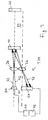
Eine weitere wichtige Anwendung betrifft den Einsatz eines erfindungsgemäßen optischen Sensors 100 als sogenannter Bahnkantensensor. Wenn in dem in
Eine weitere einfache und wichtige Anwendung der vorliegenden Erfindung kann ebenfalls mit Bezug auf
Ein wesentlicher Vorteil des erfindungsgemäßen optischen Sensors ist, dass alle vorstehend erläuterten Funktionalitäten prinzipiell in einem einzigen Sensor integriert werden können. Beispielsweise können über Schalter die entsprechenden Modi auswählbar sein oder es wird für jede Funktion ein separater Ausgang zur Verfügung gestellt. Der Vorteil hierbei betrifft sowohl den Anwender, der für verschiedene Anwendungen denselben Sensor verwendet und damit Aufwand in der Logistik spart als auch den Sensorhersteller. Die höhere Funktionalität sichert eine höhere zu fertigende Stückzahl und somit auch geringere Herstellungskosten.An essential advantage of the optical sensor according to the invention is that all the above-described functionalities can in principle be integrated in a single sensor. For example, the corresponding modes can be selected via switches, or a separate output is made available for each function. The advantage here is both the user who uses the same sensor for different applications and thus saves effort in logistics and the sensor manufacturer. The higher functionality ensures a higher number of pieces to be manufactured and thus lower production costs.
Die Möglichkeiten der Bahnkantenerkennung werden im Zusammenhang mit den
In einem Abstand 44 vom Sensor 100 ist ein Retroreflektor 60 angeordnet, der das eingestrahlte Licht 22, 42 in Richtung des Sensors 100 zurückreflektiert oder -streut.At a
Die Kernidee des in
Um den zulässigen Bereich des Objekts 10 möglichst klein zu halten und damit eine sehr präzise Positionierung zu realisieren, muss der Sensor 100 in der Lage sein, auch sehr kleine Kontraste des Empfangssignals auszuwerten. So kann beispielsweise gefordert werden, und dies kann auch mit Hilfe der Erfindung realisiert werden, dass bereits eine Unterschreitung des eingelernten Werts um 5% zu einem Schalten eines Ausgangs oder andererseits eine Überschreitung um 5% zum Schalten des anderen Ausgangs führt.In order to keep the permissible range of the
Zusätzlich zum Objekt 10 können aber auch sonstige Umweltbedingungen Einfluss auf das Empfangssignal haben. Im Allgemeinen sind die Eigenschaften von elektronischen Bauelementen temperaturabhängig, so dass sich das Empfangssignal mit der Temperatur ändert. Beispielsweise führt eine Verschmutzung einer Frontscheibe des Sensors oder des Retroreflektors zu einer Verringerung des Empfangssignals. Die Folge dieser Einflüsse wäre eine Verschiebung der Objektpositionen, in denen die Ausgänge schalten. Um die Schaltpunkte unabhängig von Umwelteinflüssen zu halten, muss eine ständige Nachregelung der Empfindlichkeit vorgenommen werden. Hierzu dient bei dem in
Die Kompensation kann beispielsweise so gestaltet werden, dass beide Kanäle über einen gemeinsamen Empfangsweg geleitet werden. Dessen Verstärkung kann dann so variiert werden, dass das resultierende Empfangssignal des unteren Kanals konstant bleibt. Eine andere Möglichkeit ist, die Schwellwerte abhängig von der Höhe des Empfangssignals des unteren Kanals zu variieren.The compensation can for example be designed so that both channels are routed via a common reception path. Its gain can then be varied so that the resulting received signal of the lower channel remains constant. Another possibility is to vary the threshold values depending on the height of the received signal of the lower channel.
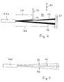
Eine weitere Möglichkeit, die Position einer Bahnkante zu bestimmen, wird mit Bezug auf die
Dieses Messprinzip lässt sich sowohl unter Verwendung eines Retroreflektors als auch im tastenden Betrieb anwenden, wenn die Empfindlichkeit der Auswertung entsprechend erhöht wird.This measurement principle can be applied both using a retroreflector and during grooving operation, if the sensitivity of the evaluation is increased accordingly.
Beispielsweise können wiederum beide Kanäle abwechselnd gepulst werden, um jeweils das Empfangssignal auswerten zu können. Eine Kante eines nachzuweisenden Objekts, dessen Position auszuwerten ist, muss sich im Überlappungsbereich 16 der beiden Kanäle befinden. Während eines Einlernvorgangs ermittelt und speichert der Sensor 100 das Verhältnis der beiden, auf das Licht 22 bzw. das Licht 42 zurückgehenden Empfangssignale. Im laufenden Messbetrieb wird sodann das Verhältnis dieser beiden Signale mit dem eingespeicherten eingelernten Wert verglichen und ausgewertet. Der Vorteil dieser Anordnung besteht darin, dass der Abstand vom Sensor und die Oberflächeneigenschaften des nachzuweisenden Objekts 10 im Wesentlichen keinen Einfluss auf den Ort der Schaltpunkte haben. Die Optik sollte hierzu so ausgelegt sein, dass der Überlappungsbereich 16 einen parallelen Strahlengang mit konstantem Durchmesser bildet, wie dies beispielsweise in
Im Hinblick auf die Geometrien der eingesetzten Strahlquerschnitte besteht grundsätzlich große Gestaltungsfreiheit. Zwei Varianten sind in den
Mit der vorliegenden Erfindung wird ein hochfunktionaler optischer Sensor und ein besonders vielseitig einsetzbares Verfahren zum Nachweis von Objekten in einem Überwachungsbereich bereitgestellt, wobei mit Hilfe einer Mehrzahl von Lichtquellen mehrere Überwachungsteilbereiche überwacht und entsprechend zwei oder mehrere Sensorausgänge angesteuert werden. Mit dem erfindungsgemäßen Sensor und dem erfindungsgemäßen Verfahren können insbesondere eine Bewegungsrichtung von Objekten, eine Positionserkennung oder eine Höhenkontrolle, bevorzugt mit einer hohen Anzahl von Sendern, durchgeführt werden. Bei einer besonders bevorzugten Anwendung wird der erfindungsgemäße optische Sensor zum Nachweis einer Bahnkantenposition oder zur Bahnkantenregelung eingesetzt. Ein Teil dieser Funktionen oder prinzipiell auch sämtliche dieser Funktionen können in einem einzigen Sensor integriert werden und es können entsprechende Wahlmittel, wie beispielsweise Umschalter oder mehrere separate Ausgänge vorgesehen sein, um die einzelnen Modi zu aktivieren.The present invention provides a highly functional optical sensor and a particularly versatile method for detecting objects in a monitoring area, with the aid of a plurality of light sources monitoring a plurality of monitoring subareas and correspondingly controlling two or more sensor outputs. With the sensor according to the invention and the invention In particular, a movement direction of objects, a position detection or a height control, preferably with a high number of transmitters, can be carried out. In a particularly preferred application, the optical sensor according to the invention is used to detect a web edge position or for web edge control. Part of these functions, or in principle all of these functions, can be integrated into a single sensor, and appropriate selection means, such as switches or several separate outputs, can be provided to activate the individual modes.
Claims (18)
mit einer Mehrzahl von Lichtsendern (20, 40) zum Aussenden von Licht (22, 42), wobei jedem Lichtsender (20, 40) ein Überwachungsteilbereich (92, 94) zugeordnet ist, in welchen der jeweilige Lichtsender (20, 40) Lichtsignale aussendet, und
mit einer Ansteuereinheit (70) zum Ansteuern der Lichtsender (20, 40),
dadurch gekennzeichnet,
dass zum Nachweis von von einem nachzuweisenden Objekt (10) reflektiertem und/oder gestreutem Licht (52) genau ein gemeinsamer Detektor (50) vorhanden ist, welcher genau ein zeitabhängiges Detektionssignal liefert,
dass die Ansteuereinheit (70) zum zeitlich jeweils unterschiedlichen Aktivieren der verschiedenen Lichtsender (20, 40) eingerichtet ist,
dass eine mit dem Detektor (50) verbundene Auswerteeinheit (72) vorhanden ist, die mit der Ansteuereinheit (70) zusammenwirkt und zum Auswerten des Detektionssignals sowie zum Zuordnen von einzelnen Anteilen des Detektionssignals zu Lichtsignalen der verschiedenen Lichtsender (20, 40) eingerichtet ist,
dass die Auswerteeinheit (72) zum Abspeichern von für das nachzuweisende Objekt (10) spezifischen Vergleichsdaten eingerichtet ist und
dass die Auswerteeinheit (72) für das Bestimmen und Ausgeben einer Position des nachzuweisenden Objekts (10) im Überwachungsbereich durch Vergleich der einzelnen Signalanteile mit den Vergleichsdaten eingerichtet ist.Optical sensor for determining the position of objects in a monitoring area (90), in particular for carrying out the method according to one of claims 9 to 18,
with a plurality of light emitters (20, 40) for emitting light (22, 42), each light emitter (20, 40) being assigned a monitoring subarea (92, 94) in which the respective light emitter (20, 40) emits light signals , and
with a drive unit (70) for driving the light transmitters (20, 40),
characterized,
in that for the detection of light (52) reflected and / or scattered by an object (10) to be detected there is exactly one common detector (50) which supplies exactly one time-dependent detection signal,
that the control unit (70) for respectively different time-activating the various light transmitters (20, 40) is arranged,
is that an evaluation unit connected to the detector (50) connected (72) is provided which cooperates with the control unit (70) and for evaluating the detection signal and for associating individual amounts of the detection signal to the light signals of the different light emitters (20, 40) is arranged to
in that the evaluation unit (72) is set up to store comparison data specific to the object to be detected (10), and
in that the evaluation unit (72) for determining and outputting a position of the object to be detected (10) in the monitoring area is set up by comparing the individual signal components with the comparison data.
dadurch gekennzeichnet,
dass ein Reflektor (60) zum Begrenzen des Überwachungsbereichs (90) vorhanden ist.Optical sensor according to claim 1,
characterized,
that a reflector (60) for limiting the monitored zone (90) is present.
dadurch gekennzeichnet,
dass der Reflektor (60) mehrteilig gebildet ist.Optical sensor according to claim 2,
characterized,
that the reflector (60) is formed in several parts.
dadurch gekennzeichnet,
dass der Detektor (50) ein einziges Detektorelement aufweist.Optical sensor according to one of claims 1 to 3,
characterized,
that the detector (50) comprises a single detector element.
dadurch gekennzeichnet,
dass genau zwei Lichtsender (20, 40) vorhanden sind.Optical sensor according to one of claims 1 to 4,
characterized,
that exactly two light transmitters (20, 40) are present.
dadurch gekennzeichnet,
dass die Überwachungsteilbereiche (92, 94) von mindestens zwei Lichtsendern (20, 40) sich überlappen.Optical sensor according to one of claims 1 to 5,
characterized,
that the monitoring portions (92, 94) of at least two light transmitters (20, 40) overlap.
dadurch gekennzeichnet,
dass zum Leiten des Lichts (22, 42) der Lichtsender (20, 40) in den Überwachungsbereich (90) eine gemeinsame Sendeoptik (34) vorhanden ist und
dass zum Leiten des Lichts (52) auf den Detektor (50) eine von der Sendeoptik (34) verschiedene Detektoroptik (36) vorhanden ist.Optical sensor according to one of claims 1 to 6,
characterized,
in that for the purpose of guiding the light (22, 42) of the light transmitters (20, 40) into the monitoring area (90) a common transmission optical system (34) is present, and
in that, for the purpose of guiding the light (52) onto the detector (50), a detector optics (36) different from the transmitting optics (34) is present.
dadurch gekennzeichnet,
dass die Lichtsender (20, 40) Infrarot-Lichtquellen, insbesondere Infrarot-Laserdioden, sind.Optical sensor according to one of claims 1 to 7,
characterized,
in that the light transmitters (20, 40) are infrared light sources, in particular infrared laser diodes.
bei dem eine Mehrzahl von Lichtsendern (20, 40) Licht (22, 42) in Überwachungsteilbereiche (92, 94) aussendet, die den Lichtsendern (20, 40) jeweils zugeordnet sind,
dadurch gekennzeichnet,
dass von dem nachzuweisenden Objekt (10) im Überwachungsbereich (90) und/oder von einem Reflektor (60) reflektiertes und/oder gestreutes Licht (52) mit genau einem gemeinsamen Detektor (50) nachgewiesen wird,
dass dem von den verschiedenen Lichtsendern (20, 40) ausgehenden Licht (22, 42) eine jeweils unterschiedliche zeitliche Struktur aufgeprägt wird,
dass das Detektorsignal bezüglich der auf die unterschiedlichen Lichtsender (20, 40) zurückgehenden Signalanteile ausgewertet wird,
dass für das nachzuweisende Objekt (10) gemessene Normalwerte der gestreuten und/oder reflektierten Lichtintensität als Vergleichsdaten eingelernt werden,
dass die auf die unterschiedlichen Lichtsender (20, 40) zurückgehenden Signalanteile des Detektorsignals mit den Vergleichsdaten verglichen werden und
dass abhängig vom Resultat dieses Vergleichs eine Position des Objektes (10) bestimmt und ausgegeben wird.Method for determining the position of objects in a surveillance area, in particular using an optical sensor according to one of claims 1 to 8,
in which a plurality of light emitters (20, 40) emit light (22, 42) into monitoring subregions (92, 94) which are respectively assigned to the light emitters (20, 40),
characterized,
that light (52) reflected and / or scattered by the object (10) to be detected in the surveillance area (90) and / or by a reflector (60) is detected with exactly one common detector (50),
that the light (22, 42) emanating from the different light emitters (20, 40) is imprinted with a different temporal structure,
that the detector signal is evaluated with respect to the signal components attributable to the different light transmitters (20, 40),
that normal values of the scattered and / or reflected light intensity measured for the object to be detected (10) are taught in as comparison data,
in that the signal components of the detector signal attributable to the different light transmitters (20, 40) are compared with the comparison data, and
that, depending on the result of this comparison, a position of the object (10) is determined and output.
dadurch gekennzeichnet,
dass die Lichtsender (20, 40) abwechselnd gepulst werden.Method according to claim 9,
characterized,
in that the light emitters (20, 40) are alternately pulsed.
dadurch gekennzeichnet,
dass ein Strahl eines Lichtsenders (20, 40) als Referenzstrahl verwendet wird, der im Normalbetrieb nicht auf das nachzuweisende Objekt (10) fällt.Method according to claim 9 or 10,
characterized,
in that a beam of a light transmitter (20, 40) is used as the reference beam, which does not fall on the object (10) to be detected in normal operation.
dadurch gekennzeichnet,
dass die Vergleichsdaten für eine Vielzahl von Positionen des Objekts (10) abgespeichert werden.Method according to one of claims 9 to 11,
characterized,
that the comparison data for a plurality of positions of the object (10) are stored.
dadurch gekennzeichnet,
dass eine Position des Objekts (10) in einer Richtung (14) quer zu einer Erstrekkungsrichtung der Hauptstrahlrichtungen der Lichtsender (20, 40) bestimmt wird.Method according to one of claims 9 to 12,
characterized,
in that a position of the object (10) in a direction (14) transverse to an extension direction of the main beam directions of the light emitters (20, 40) is determined.
dadurch gekennzeichnet,
dass auch eine Bewegungsrichtung des Objekts (10) bestimmt und ausgegeben wird.Method according to one of claims 9 to 13,
characterized,
that a direction of movement of the object (10) is determined and output.
dadurch gekennzeichnet,
dass das zu überwachende Objekt (10) eine Kante (12) eines bahnartigen Materials ist und
dass der optische Sensor (100) bezüglich der Kante (12) so positioniert wird, dass mindestens für den Strahlengang eines Lichtsenders (20) ein Teil des Lichts (22) durchgelassen wird und ein weiterer Teil von der Kante (12) abgeblockt wird.Method according to one of claims 9 to 14,
characterized,
that the object to be monitored (10) is an edge (12) of a web-like material and
in that the optical sensor (100) is positioned with respect to the edge (12) such that at least for the beam path of a light transmitter (20) a part of the light (22) is transmitted and another part is blocked by the edge (12).
dadurch gekennzeichnet,
dass für die zu überwachenden Objekte (10) eine Höhenkontrolle durchgeführt wird.Method according to one of claims 9 to 15,
characterized,
that, for the objects to be monitored (10) is performed a height control.
dadurch gekennzeichnet,
dass das zu überwachende Objekt eine Streifenstruktur aufweist, welche Schaltvorgänge des optischen Sensors (100) auslösen kann und
dass der optische Sensor (100) als Inkrementalgeber betrieben wird.Method according to one of claims 9 to 16,
characterized,
that the object to be monitored has a strip structure which can initiate switching operations of the optical sensor (100) and
that the optical sensor (100) is operated as incremental encoder.
dadurch gekennzeichnet,
dass mindestens ein Verhältnis (18) von auf verschiedene Lichtsender (20, 40) zurückgehenden Signalanteilen des Detektorsignals gebildet und ausgewertet wird.Method according to one of claims 9 to 17,
characterized,
in that at least one ratio (18) of signal portions of the detector signal attributable to different light transmitters (20, 40) is formed and evaluated.
Applications Claiming Priority (1)
| Application Number | Priority Date | Filing Date | Title |
|---|---|---|---|
| DE102007054596A DE102007054596A1 (en) | 2007-11-15 | 2007-11-15 | Optical sensor and method for determining the position of objects |
Publications (2)
| Publication Number | Publication Date |
|---|---|
| EP2065732A2 true EP2065732A2 (en) | 2009-06-03 |
| EP2065732A3 EP2065732A3 (en) | 2010-02-17 |
Family
ID=40350096
Family Applications (1)
| Application Number | Title | Priority Date | Filing Date |
|---|---|---|---|
| EP08019966A Withdrawn EP2065732A3 (en) | 2007-11-15 | 2008-11-14 | Optical sensor and method for determining the position of objects |
Country Status (2)
| Country | Link |
|---|---|
| EP (1) | EP2065732A3 (en) |
| DE (1) | DE102007054596A1 (en) |
Families Citing this family (3)
| Publication number | Priority date | Publication date | Assignee | Title |
|---|---|---|---|---|
| DE102011014195B4 (en) | 2010-03-19 | 2022-04-21 | Leuze Electronic Gmbh & Co. Kg | optical sensor |
| US9857472B2 (en) | 2013-07-02 | 2018-01-02 | Electronics And Telecommunications Research Institute | Laser radar system for obtaining a 3D image |
| DE102017222769B4 (en) * | 2017-12-14 | 2019-09-26 | Jenoptik Optical Systems Gmbh | Angle measuring device and method for determining a tilt angle of a reflection element by means of an angle measuring device |
Citations (11)
| Publication number | Priority date | Publication date | Assignee | Title |
|---|---|---|---|---|
| US4184080A (en) | 1977-06-30 | 1980-01-15 | Molins Machine Company, Inc. | Ratiometric edge detector system |
| US4716298A (en) | 1984-06-01 | 1987-12-29 | Nissan Motor Company, Limited | System for automatically detecting presence or absence of a preceding vehicle and method therefor |
| DE3919917C2 (en) | 1989-06-19 | 1991-06-27 | Pepperl & Fuchs Gmbh, 6800 Mannheim, De | |
| DE19653312C1 (en) | 1996-12-20 | 1998-04-02 | Fife Gmbh | Detector for edge of belt between retro-reflector and sensor |
| DE10055689A1 (en) | 2000-11-06 | 2002-05-16 | Pepperl & Fuchs Visolux Gmbh | Optical triangulation grating sensor for checking safety areas, e.g. under or on the edges of revolving doors, where light emitting arrays are used with matching linear light detectors, to provide reliable object detection |
| EP1154225B1 (en) | 2000-05-10 | 2004-10-27 | ERHARDT + LEIMER GmbH | Detection of an edge of, or marking on, a moving product web with an additional diffuse light source as well as a light pointer |
| EP1498747A1 (en) | 2003-07-16 | 2005-01-19 | Leuze electronic GmbH + Co KG | Optoelectronic device |
| EP1528411A1 (en) | 2003-10-27 | 2005-05-04 | Bea S.A. | Distance measurement sensor |
| EP1722191A1 (en) | 2000-11-29 | 2006-11-15 | Sick Ag | Distance determination |
| DE102005033349A1 (en) | 2004-08-11 | 2007-01-25 | Leuze Electronic Gmbh & Co Kg | Light barrier monitoring object detection optical sensor has transmitter and receiver with additional transmitter and receiver for second reflected light beam from object |
| EP1832896A1 (en) | 2006-03-10 | 2007-09-12 | Pepperl + Fuchs Gmbh | Reflection light barrier with auxiliary radiation source for detecting objects in a surveillance area |
-
2007
- 2007-11-15 DE DE102007054596A patent/DE102007054596A1/en not_active Withdrawn
-
2008
- 2008-11-14 EP EP08019966A patent/EP2065732A3/en not_active Withdrawn
Patent Citations (12)
| Publication number | Priority date | Publication date | Assignee | Title |
|---|---|---|---|---|
| US4184080A (en) | 1977-06-30 | 1980-01-15 | Molins Machine Company, Inc. | Ratiometric edge detector system |
| US4716298A (en) | 1984-06-01 | 1987-12-29 | Nissan Motor Company, Limited | System for automatically detecting presence or absence of a preceding vehicle and method therefor |
| DE3919917C2 (en) | 1989-06-19 | 1991-06-27 | Pepperl & Fuchs Gmbh, 6800 Mannheim, De | |
| DE19653312C1 (en) | 1996-12-20 | 1998-04-02 | Fife Gmbh | Detector for edge of belt between retro-reflector and sensor |
| EP1154225B1 (en) | 2000-05-10 | 2004-10-27 | ERHARDT + LEIMER GmbH | Detection of an edge of, or marking on, a moving product web with an additional diffuse light source as well as a light pointer |
| DE10055689A1 (en) | 2000-11-06 | 2002-05-16 | Pepperl & Fuchs Visolux Gmbh | Optical triangulation grating sensor for checking safety areas, e.g. under or on the edges of revolving doors, where light emitting arrays are used with matching linear light detectors, to provide reliable object detection |
| EP1722191A1 (en) | 2000-11-29 | 2006-11-15 | Sick Ag | Distance determination |
| EP1498747A1 (en) | 2003-07-16 | 2005-01-19 | Leuze electronic GmbH + Co KG | Optoelectronic device |
| EP1528411A1 (en) | 2003-10-27 | 2005-05-04 | Bea S.A. | Distance measurement sensor |
| DE102005033349A1 (en) | 2004-08-11 | 2007-01-25 | Leuze Electronic Gmbh & Co Kg | Light barrier monitoring object detection optical sensor has transmitter and receiver with additional transmitter and receiver for second reflected light beam from object |
| EP1832896A1 (en) | 2006-03-10 | 2007-09-12 | Pepperl + Fuchs Gmbh | Reflection light barrier with auxiliary radiation source for detecting objects in a surveillance area |
| DE102006011250A1 (en) | 2006-03-10 | 2007-09-13 | Pepperl + Fuchs Gmbh | Reflection light barrier for detection of objects in a surveillance area and method for their operation |
Also Published As
| Publication number | Publication date |
|---|---|
| EP2065732A3 (en) | 2010-02-17 |
| DE102007054596A1 (en) | 2009-05-20 |
Similar Documents
| Publication | Publication Date | Title |
|---|---|---|
| EP2453252B1 (en) | Energy efficient 3D sensor | |
| DE10301971B4 (en) | Positioning device | |
| DE202005007089U1 (en) | Sensor arrangement for optically detecting the edges of a product, e.g. to measure its width, comprises point light sources and a optical fiber arrangement that detects light reflected back from the product under-surface | |
| EP1355128B1 (en) | Automatic alignment of a sensor | |
| EP0892280A2 (en) | Method for operating an opto-electronic sensor device | |
| EP0379097A2 (en) | Process for determining the position of the rim of an object, photo-electronic sensing device to trace the rim | |
| DE19911375A1 (en) | Missile position detection device for practice firing, includes transmitter for transmitting light-beam into zone of intersection of fields of view | |
| EP1718925A1 (en) | Scanning head for a coordinate measuring device | |
| EP2065732A2 (en) | Optical sensor and method for determining the position of objects | |
| DE19914962C2 (en) | Optoelectronic device | |
| WO2010063521A2 (en) | Optical measuring arrangement and optical measuring method | |
| DE102004003386B4 (en) | Optical sensor | |
| DE102021112212A1 (en) | Optical sensor and method of operating an optical sensor | |
| EP2306145A1 (en) | Optical sensor | |
| DE202006003841U1 (en) | Object detection unit for light barrier system has additional detectors for scattered radiation place outside path of direct reflection | |
| EP2851704B1 (en) | Apparatus and method for optically identifying the distances between objects in a monitoring area | |
| WO2006092300A2 (en) | Sensor assembly for optically detecting the edges of a product and width-measurement method | |
| EP1148352B1 (en) | Optical sensor | |
| DE3336726A1 (en) | Edge sensing apparatus | |
| DE1524368B2 (en) | Device for scanning hole strips | |
| EP2578991A1 (en) | Optical sensor | |
| DE102007036632B4 (en) | Optical sensor and method for detecting objects in a surveillance area | |
| EP1278051B1 (en) | Lens assembly for movement sensor | |
| DE202005002622U1 (en) | Optical position sensor has reference scale with zones of different reflectivity and sensor plate of different transmission to generate reference pulse | |
| DE2448571C3 (en) | Arrangement for non-contact measurement of dimensions, such as diameter, cross-section or the like. of an object |
Legal Events
| Date | Code | Title | Description |
|---|---|---|---|
| PUAI | Public reference made under article 153(3) epc to a published international application that has entered the european phase |
Free format text: ORIGINAL CODE: 0009012 |
|
| AK | Designated contracting states |
Kind code of ref document: A2 Designated state(s): AT BE BG CH CY CZ DE DK EE ES FI FR GB GR HR HU IE IS IT LI LT LU LV MC MT NL NO PL PT RO SE SI SK TR |
|
| AX | Request for extension of the european patent |
Extension state: AL BA MK RS |
|
| PUAL | Search report despatched |
Free format text: ORIGINAL CODE: 0009013 |
|
| AK | Designated contracting states |
Kind code of ref document: A3 Designated state(s): AT BE BG CH CY CZ DE DK EE ES FI FR GB GR HR HU IE IS IT LI LT LU LV MC MT NL NO PL PT RO SE SI SK TR |
|
| AX | Request for extension of the european patent |
Extension state: AL BA MK RS |
|
| RIC1 | Information provided on ipc code assigned before grant |
Ipc: G01B 11/02 20060101ALI20100108BHEP Ipc: G01S 17/06 20060101AFI20090220BHEP |
|
| 17P | Request for examination filed |
Effective date: 20100810 |
|
| 17Q | First examination report despatched |
Effective date: 20100907 |
|
| AKX | Designation fees paid |
Designated state(s): AT BE BG CH CY CZ DE DK EE ES FI FR GB GR HR HU IE IS IT LI LT LU LV MC MT NL NO PL PT RO SE SI SK TR |
|
| STAA | Information on the status of an ep patent application or granted ep patent |
Free format text: STATUS: THE APPLICATION IS DEEMED TO BE WITHDRAWN |
|
| 18D | Application deemed to be withdrawn |
Effective date: 20120614 |