EP2066412B1 - Detecting ventilator system anomalies while in a speaking mode - Google Patents
Detecting ventilator system anomalies while in a speaking mode Download PDFInfo
- Publication number
- EP2066412B1 EP2066412B1 EP07842070.0A EP07842070A EP2066412B1 EP 2066412 B1 EP2066412 B1 EP 2066412B1 EP 07842070 A EP07842070 A EP 07842070A EP 2066412 B1 EP2066412 B1 EP 2066412B1
- Authority
- EP
- European Patent Office
- Prior art keywords
- exhalation
- patient
- inhalation
- valve
- pressure
- Prior art date
- Legal status (The legal status is an assumption and is not a legal conclusion. Google has not performed a legal analysis and makes no representation as to the accuracy of the status listed.)
- Active
Links
- 210000004072 lung Anatomy 0.000 claims description 31
- 210000001260 vocal cord Anatomy 0.000 claims description 14
- 238000009423 ventilation Methods 0.000 claims description 13
- 230000000241 respiratory effect Effects 0.000 claims description 6
- 230000003252 repetitive effect Effects 0.000 claims description 4
- 210000003437 trachea Anatomy 0.000 claims description 4
- 239000007789 gas Substances 0.000 description 39
- 230000029058 respiratory gaseous exchange Effects 0.000 description 14
- 238000012544 monitoring process Methods 0.000 description 10
- 238000000034 method Methods 0.000 description 9
- 238000001514 detection method Methods 0.000 description 7
- 230000003434 inspiratory effect Effects 0.000 description 7
- 230000008901 benefit Effects 0.000 description 5
- QVGXLLKOCUKJST-UHFFFAOYSA-N atomic oxygen Chemical compound [O] QVGXLLKOCUKJST-UHFFFAOYSA-N 0.000 description 4
- 210000003205 muscle Anatomy 0.000 description 4
- 239000001301 oxygen Substances 0.000 description 4
- 229910052760 oxygen Inorganic materials 0.000 description 4
- 238000009530 blood pressure measurement Methods 0.000 description 3
- 238000004891 communication Methods 0.000 description 3
- 238000010586 diagram Methods 0.000 description 3
- 230000001960 triggered effect Effects 0.000 description 3
- 230000009471 action Effects 0.000 description 2
- 239000000443 aerosol Substances 0.000 description 2
- 230000000694 effects Effects 0.000 description 2
- 239000012528 membrane Substances 0.000 description 2
- 238000011282 treatment Methods 0.000 description 2
- 206010003497 Asphyxia Diseases 0.000 description 1
- 206010011224 Cough Diseases 0.000 description 1
- 206010036790 Productive cough Diseases 0.000 description 1
- 230000002411 adverse Effects 0.000 description 1
- 208000008784 apnea Diseases 0.000 description 1
- 230000000712 assembly Effects 0.000 description 1
- 238000000429 assembly Methods 0.000 description 1
- 230000036760 body temperature Effects 0.000 description 1
- 238000010276 construction Methods 0.000 description 1
- 238000011513 continuous positive airway pressure therapy Methods 0.000 description 1
- 238000007796 conventional method Methods 0.000 description 1
- 210000000188 diaphragm Anatomy 0.000 description 1
- 230000002708 enhancing effect Effects 0.000 description 1
- 210000004704 glottis Anatomy 0.000 description 1
- 230000000977 initiatory effect Effects 0.000 description 1
- 230000010354 integration Effects 0.000 description 1
- 210000000876 intercostal muscle Anatomy 0.000 description 1
- 238000004519 manufacturing process Methods 0.000 description 1
- 230000007246 mechanism Effects 0.000 description 1
- 238000012986 modification Methods 0.000 description 1
- 230000004048 modification Effects 0.000 description 1
- 230000010355 oscillation Effects 0.000 description 1
- 210000002976 pectoralis muscle Anatomy 0.000 description 1
- 230000008569 process Effects 0.000 description 1
- 229920006395 saturated elastomer Polymers 0.000 description 1
- 208000024794 sputum Diseases 0.000 description 1
- 210000003802 sputum Anatomy 0.000 description 1
- 230000000153 supplemental effect Effects 0.000 description 1
- 238000012360 testing method Methods 0.000 description 1
- 238000002560 therapeutic procedure Methods 0.000 description 1
- 210000000115 thoracic cavity Anatomy 0.000 description 1
- 230000001755 vocal effect Effects 0.000 description 1
- XLYOFNOQVPJJNP-UHFFFAOYSA-N water Substances O XLYOFNOQVPJJNP-UHFFFAOYSA-N 0.000 description 1
Images


Classifications
-
- A—HUMAN NECESSITIES
- A61—MEDICAL OR VETERINARY SCIENCE; HYGIENE
- A61M—DEVICES FOR INTRODUCING MEDIA INTO, OR ONTO, THE BODY; DEVICES FOR TRANSDUCING BODY MEDIA OR FOR TAKING MEDIA FROM THE BODY; DEVICES FOR PRODUCING OR ENDING SLEEP OR STUPOR
- A61M16/00—Devices for influencing the respiratory system of patients by gas treatment, e.g. mouth-to-mouth respiration; Tracheal tubes
- A61M16/04—Tracheal tubes
- A61M16/0465—Tracheostomy tubes; Devices for performing a tracheostomy; Accessories therefor, e.g. masks, filters
- A61M16/0468—Tracheostomy tubes; Devices for performing a tracheostomy; Accessories therefor, e.g. masks, filters with valves at the proximal end limiting exhalation, e.g. during speaking or coughing
-
- A—HUMAN NECESSITIES
- A61—MEDICAL OR VETERINARY SCIENCE; HYGIENE
- A61M—DEVICES FOR INTRODUCING MEDIA INTO, OR ONTO, THE BODY; DEVICES FOR TRANSDUCING BODY MEDIA OR FOR TAKING MEDIA FROM THE BODY; DEVICES FOR PRODUCING OR ENDING SLEEP OR STUPOR
- A61M16/00—Devices for influencing the respiratory system of patients by gas treatment, e.g. mouth-to-mouth respiration; Tracheal tubes
- A61M16/04—Tracheal tubes
- A61M16/0402—Special features for tracheal tubes not otherwise provided for
- A61M16/042—Special features for tracheal tubes not otherwise provided for with separate conduits for in-and expiration gas, e.g. for limited dead volume
-
- A—HUMAN NECESSITIES
- A61—MEDICAL OR VETERINARY SCIENCE; HYGIENE
- A61M—DEVICES FOR INTRODUCING MEDIA INTO, OR ONTO, THE BODY; DEVICES FOR TRANSDUCING BODY MEDIA OR FOR TAKING MEDIA FROM THE BODY; DEVICES FOR PRODUCING OR ENDING SLEEP OR STUPOR
- A61M16/00—Devices for influencing the respiratory system of patients by gas treatment, e.g. mouth-to-mouth respiration; Tracheal tubes
- A61M16/08—Bellows; Connecting tubes ; Water traps; Patient circuits
- A61M16/0816—Joints or connectors
- A61M16/0833—T- or Y-type connectors, e.g. Y-piece
-
- A—HUMAN NECESSITIES
- A61—MEDICAL OR VETERINARY SCIENCE; HYGIENE
- A61M—DEVICES FOR INTRODUCING MEDIA INTO, OR ONTO, THE BODY; DEVICES FOR TRANSDUCING BODY MEDIA OR FOR TAKING MEDIA FROM THE BODY; DEVICES FOR PRODUCING OR ENDING SLEEP OR STUPOR
- A61M16/00—Devices for influencing the respiratory system of patients by gas treatment, e.g. mouth-to-mouth respiration; Tracheal tubes
- A61M16/20—Valves specially adapted to medical respiratory devices
- A61M16/201—Controlled valves
- A61M16/202—Controlled valves electrically actuated
- A61M16/203—Proportional
- A61M16/204—Proportional used for inhalation control
-
- A—HUMAN NECESSITIES
- A61—MEDICAL OR VETERINARY SCIENCE; HYGIENE
- A61M—DEVICES FOR INTRODUCING MEDIA INTO, OR ONTO, THE BODY; DEVICES FOR TRANSDUCING BODY MEDIA OR FOR TAKING MEDIA FROM THE BODY; DEVICES FOR PRODUCING OR ENDING SLEEP OR STUPOR
- A61M16/00—Devices for influencing the respiratory system of patients by gas treatment, e.g. mouth-to-mouth respiration; Tracheal tubes
- A61M16/20—Valves specially adapted to medical respiratory devices
- A61M16/201—Controlled valves
- A61M16/202—Controlled valves electrically actuated
- A61M16/203—Proportional
- A61M16/205—Proportional used for exhalation control
-
- A—HUMAN NECESSITIES
- A61—MEDICAL OR VETERINARY SCIENCE; HYGIENE
- A61M—DEVICES FOR INTRODUCING MEDIA INTO, OR ONTO, THE BODY; DEVICES FOR TRANSDUCING BODY MEDIA OR FOR TAKING MEDIA FROM THE BODY; DEVICES FOR PRODUCING OR ENDING SLEEP OR STUPOR
- A61M16/00—Devices for influencing the respiratory system of patients by gas treatment, e.g. mouth-to-mouth respiration; Tracheal tubes
- A61M16/0003—Accessories therefor, e.g. sensors, vibrators, negative pressure
- A61M2016/0015—Accessories therefor, e.g. sensors, vibrators, negative pressure inhalation detectors
- A61M2016/0018—Accessories therefor, e.g. sensors, vibrators, negative pressure inhalation detectors electrical
- A61M2016/0021—Accessories therefor, e.g. sensors, vibrators, negative pressure inhalation detectors electrical with a proportional output signal, e.g. from a thermistor
-
- A—HUMAN NECESSITIES
- A61—MEDICAL OR VETERINARY SCIENCE; HYGIENE
- A61M—DEVICES FOR INTRODUCING MEDIA INTO, OR ONTO, THE BODY; DEVICES FOR TRANSDUCING BODY MEDIA OR FOR TAKING MEDIA FROM THE BODY; DEVICES FOR PRODUCING OR ENDING SLEEP OR STUPOR
- A61M16/00—Devices for influencing the respiratory system of patients by gas treatment, e.g. mouth-to-mouth respiration; Tracheal tubes
- A61M16/0003—Accessories therefor, e.g. sensors, vibrators, negative pressure
- A61M2016/0027—Accessories therefor, e.g. sensors, vibrators, negative pressure pressure meter
-
- A—HUMAN NECESSITIES
- A61—MEDICAL OR VETERINARY SCIENCE; HYGIENE
- A61M—DEVICES FOR INTRODUCING MEDIA INTO, OR ONTO, THE BODY; DEVICES FOR TRANSDUCING BODY MEDIA OR FOR TAKING MEDIA FROM THE BODY; DEVICES FOR PRODUCING OR ENDING SLEEP OR STUPOR
- A61M39/00—Tubes, tube connectors, tube couplings, valves, access sites or the like, specially adapted for medical use
- A61M39/10—Tube connectors; Tube couplings
- A61M2039/1005—Detection of disconnection
-
- A—HUMAN NECESSITIES
- A61—MEDICAL OR VETERINARY SCIENCE; HYGIENE
- A61M—DEVICES FOR INTRODUCING MEDIA INTO, OR ONTO, THE BODY; DEVICES FOR TRANSDUCING BODY MEDIA OR FOR TAKING MEDIA FROM THE BODY; DEVICES FOR PRODUCING OR ENDING SLEEP OR STUPOR
- A61M2202/00—Special media to be introduced, removed or treated
- A61M2202/02—Gases
- A61M2202/0208—Oxygen
Description
- This application relates to ventilation of a patient, and, to an apparatus for invasive ventilation that allows the patient to speak while being ventilated and that detect system anomalies when the ventilator is operating in a speaking mode.
- An example of a known endotracheal tube assembly is disclosed in
U.S. Patent No. 4,759,356 ("the '356 patent'). An example of a known ventilator assembly is disclosed inU.S. Patent No. 6,543,449 ("the '449 patent'). - The endotracheal tube assembly disclosed in the '356 patent includes an endotracheal tube configured to be installed into a patient's trachea so that an inner open end communicates with the patient's airway and lungs and an outer open end is suitably anchored exteriorly of the patient's neck. The '356 patent discloses the provision of a check valve on the open end of the tube, often referred to in the art as a "talking valve." The check valve disclosed in the '356 patent is in widespread use and the '356 patent specification indicates many advantages of the check valve when in use in addition to the basic talking advantage function.
- The ventilator assembly disclosed in the '449 patent has the capability of invasive use, as with an endotracheal tube assembly, or non-invasive use, as with a mask. The present invention focuses on the invasive mode of ventilator operation.
- As stated in the '356 patent, there are many advantages in addition to the talking capability which result from the use of a check valve. However, there are disadvantages as well. For example, the check valve should be removed in order to give the patient aerosol treatments or to perform suctioning.
-
U.S. Patent No. 6,668,824 ("the '824 patent) teaches detecting tubing circuit disconnection and occlusions. The algorithm used in the '824 patent to detect circuit disconnections and occlusions requires detecting the exhalation gas flow during the exhalation phase of a breath, i.e., detecting the flow of gas traveling through the expiratory limb of the patient circuit during exhalation. The exhalation flow, in combination with at least one other monitored parameter, such as exhalation pressure, is used to detect circuit disconnections and occlusions. This technique, however, cannot be used if the ventilation mode implemented by the ventilator specifically avoids or does not require a flow of gas in the expiratory limb during exhalation. -
WO 2004/084982 discloses a breathing assistance apparatus capable of operating in alternating inhalation and expiratory phases. -
US 2004/103896 discloses a medical ventilator system and method that triggers and/or cycles based on patient effort, which is determined from cross-correlating patient flow and patient pressure. -
US 2004/123868 discloses a tracheotomy valve unit for use with a tracheotomy valve. - The present invention is defined in
claim 1 and provides a patient ventilating apparatus that is capable of operating in a speaking mode that allows the patient to speak while receiving the ventilation therapy and that monitors for anomalies to maximize the safety of the ventilator while in the speaking mode. This object is achieved according to one embodiment of the present invention by providing a patient ventilating apparatus that includes an endotracheal tube constructed and arranged to be installed into a patient's trachea below the patient's vocal cords so that an exterior open end thereof is exterior of the patient and an interior open end thereof communicates with the patient's airway and lungs; a conduit adapted to be connected to the exterior open end of the endotracheal tube. The conduit includes inhalation and exhalation passages communicating with one another. The patient ventilator assembly also includes inhalation and exhalation valves in the inhalation and exhalation passages, respectively, and a pressure sensor adapted to monitor a pressure within at least one of the passages during the exhalation phase. A controller controls the inhalation valve and the exhalation valve so as to provide repetitive respiratory cycles, each respiratory cycle including an inhalation phase and an exhalation phase. During the inhalation phase the inhalation valve is open and the exhalation valve is closed and a flow of gas is allowed to pass through the inhalation passage and the tube into the patient's airway and lungs. The controller is further adapted to determine whether a circuit disconnect or an occlusion exists based on the monitored pressure. - The endotracheal tube has a check valve in the exterior open end thereof.
- These and other objects, features, and characteristics of the present invention, as well as the methods of operation and functions of the related elements of structure and the combination of parts and economies of manufacture, will become more apparent upon consideration of the following description and the appended claims with reference to the accompanying drawings, all of which form a part of this specification, wherein like reference numerals designate corresponding parts in the various FIGS.. It is to be expressly understood, however, that the drawings are for the purpose of illustration and description only and are not intended as a definition of the limits of the invention. As used in the specification and in the claims, the singular form of "a", "an", and "the" include plural referents unless the context clearly dictates otherwise.
-
-
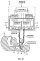
FIG. 1A is a partially schematic view of an embodiment of a ventilating apparatus according to one aspect of the invention, the apparatus being shown operatively connected with a patient with arrows indicating the direction of gas flow when the valves and controller are in an inhalation phase; -
FIG. 1B is a view similar to 1A, but showing a partially closed exhalation valve; -
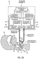
FIG. 2A is a partially schematic view of the embodiment ofFIG. 1A , but showing arrows indicating the direction of flow when the valves and controller are in a talking mode exhalation phase; -
FIG. 2B is a view similar to 2A, but showing a partially closed exhalation valve and a partially closed inhalation valve; -
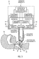
FIG. 3 is a partially schematic view of the embodiment ofFIG. 1A , but showing arrows indicating the direction of flow when the valves and controller are in a non-talking mode exhalation phase; -
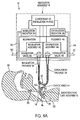
FIG. 4A illustrates another embodiment of the present invention wherein the endotracheal tube, rather than being devoid of a check valve as inFIG. 1A , has a check valve in the open end thereof; -
FIG. 4B is a view similar to 4A, but showing a partially closed exhalation valve; -
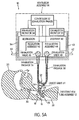
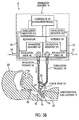
FIG. 5A is a view similar toFIG. 4A , but showing arrows indicating the direction of flow when the valves and controller are in an exhalation phase; -
FIG. 5B is a view similar toFIG. 5A , but showing partially closed exhalation and inhalation valves; -
FIG. 6 schematically depicts the system ofFIGS. 1 and2 as an analogous electric circuit diagram, and showing an arrangement in which the exhalation valve is completely closed during the inhalation and exhalation phases; and -
FIGS. 7A and 7B are graphs illustrating an occlusion detection technique according to one embodiment of the present invention. - Referring now more particularly to
FIGS. 1A ,1B ,2A ,2B , and3 (or "FIGS. 1-3 " for short) of the drawings, there is shown a ventilating apparatus, generally indicated at 10, embodying the principles of the present invention.Ventilating apparatus 10 includes, in general, an endotracheal tube assembly, generally indicated at 12, and a ventilator assembly, generally indicated at 14. -
Endotracheal tube assembly 12 includes anendotracheal tube 16, constructed, for example, in accordance with the principles disclosed in the '356 patent.Endotracheal tube 16 is constructed and arranged to be mounted in atrachea 18 of apatient 20, as shown inFIGS.1-3 , so that an exterioropen end 22 is suitably fixed in position exteriorly of the patient'sneck 24 and an interioropen end 26 communicates with the patient's airway andlungs 28 at a position below the patient'svocal cords 30. - In
FIGS.1-3 ,endotracheal tube 18 is shown as being devoid of a check valve, often referred to as the talking valve, such as the one disclosed in the '356 patent. -
Ventilator assembly 14 includes a conduit assembly, generally indicated at 32, which includes a Y fitting 34 and tubing portions forming aninhalation passage 36 and anexhalation passage 38, as will be described below. The stem of Y fitting 34 is connected over exterioropen end 22 ofendotracheal tube 16 so that endotracheal tube is devoid of a check valve and communicates withconduit assembly 32 for gaseous flow therethrough in either direction. - One branch of the Y fitting is connected with the tubing or conduit section defining
inhalation passage 36 and the other branch of the Y fitting is connected with the tubing or conduit section definingexhalation passage 38. As can be seen fromFIGS. 1-3 , Y fitting 34 serves to communicateinhalation passage 36 andexhalation passage 38 with one another. -
Conduit assembly 32 thus far described is disposed exteriorly ofventilator assembly 14, as indicated by broken lines inFIGS. 1-3 .Ventilator assembly 14 houses arespiration assembly 40 therein, which includes aninhalation assembly 42 and anexhalation assembly 44. InFIGS. 1-3 ,inhalation assembly 42 andexhalation assembly 44 ofrespiration assembly 40 are shown schematically in a block diagram. The gas flow components included in inhalation andexhalation assemblies respiration assembly 40 can be of conventional construction. A specific disclosure of one embodiment of the components used in accordance with the principles of the present invention is disclosed in the '449 patent. - As illustrated,
inhalation assembly 42 includes acontrollable inhalation valve 46 that communicates withinhalation passage 36, andexhalation assembly 44 includes acontrollable exhalation valve 48 that communicates withexhalation passage 36. -
Valves controller 52 and are capable of being controlled to move between fully closed and fully open and any position of partial opening therebetween.Valves -
Respiration assembly 40 is constructed and arranged to be controlled to provide repetitive respiratory cycles. Each respiration cycle includes an inhalation phase during whichinhalation valve 46 is open andexhalation valve 48 is closed. During each inhalation phase,inhalation assembly 42 is controlled bycontroller 52 to cause a flow of gas to pass through theopen inhalation valve 46,inhalation passage 36,endotracheal tube 16 into the patient's airway andlungs 28. In one embodiment, the flow of gas includes air and oxygen mixed byinhalation assembly 42 from a supply of air drawn through an andinlet 50 ofinhalation assembly 42 and a supply of oxygen contained withininhalation assembly 42. However, any known source of gas can be used and communicated throughinhalation passage 36 viainhalation valve 46. - Each respiration cycle also includes an exhalation phase during which
inhalation valve 46 is closed or partially closed (i.e., "relatively" closed as discussed later). - As best shown in
FIGS. 2A and2B , in accordance with an embodiment of the invention, ventilatingapparatus 10 is adapted to be operated in a "speaking mode" in whichexhalation valve 48 is controlled bycontroller 52 to remain in its relatively closed position, or to dynamically control the pressure inconduit assembly 32 in accordance with a desired pressure profile, during the exhalation phase, with the pressure profile being based upon the objective of enhancing the patient's ability to speak. This control ofexhalation valve 48 enables the exhalation phase to be one in which the ability of the patient to talk is facilitated, even though there is no check valve embodied inendotracheal assembly 12 orconduit assembly 32. Thus, during the exhalation phase, when the patient is able to exhale the breathable gas introduced into the patient's airway and lungs in the preceding inhalation phase, the relatively closed inhalation andexhalation valves conduit assembly 32, so that the exhaled gas must flow passed the patient'svocal cords 30 on its way out of the patient's mouth, thus facilitating the patient's ability to talk, as shown by the arrows inFIGS. 2A and2B . - It should be appreciated that in instances in which the inhalation valve or exhalation valve is disclosed herein as being "closed" or "open," this is not meant to necessarily refer to an absolute or fully open or fully closed valve (although it may), but rather a relational open or closed valve. In other words, for example, when the exhalation valve is "closed", this does not mean that it is completely closed to prevent any gas passage therethrough, as shown in
FIGS.1A and2A . Rather, the exhalation valve may be partially closed, but closed sufficiently to achieve its desired functionality (as shown inFIGS. 1B and2B ). Thus, for example, a "relatively closed" or "relatively open" exhalation valve means a relatively closed position and a comparatively, relatively open position, respectively, as it relates to that particular valve. Similarly, a "closed" or "open" inhalation valve refers to two relative positions of the inhalation valve, wherein one position is relatively closed or relatively open with respect to the other. Thus, the term "relatively closed" as used herein is intended to convey this broad understanding and meaning. - In the inhalation phase, for example, the exhalation valve need not be fully closed, but may be closed only enough to enable a desired pressure to build within
conduit assembly 32 and the patient's lungs. Similarly, in the inhalation phase, the inhalation valve need not be fully open, but may be open only enough to draw sufficient gas intoconduit assembly 32 and patient's lungs to enable the patient to breath (not shown in the FIGS.). Similarly, in the exhalation phase, the inhalation valve need not be fully closed, but may be partially closed (seeFIG. 2B ), and the exhalation valve need only be closed sufficiently to maintain a desired profile of pressure in conduit assembly 32 (seeFIG. 2B ). - In one embodiment, the degree of opening and closing of the exhalation valve and/or inhalation valve is dynamically controlled by
controller 52. Specifically, exhalation monitor 58 and/or inhalation monitor 54 can be used to monitor pressure throughout, or periodically during, the inhalation and/or exhalation phase and send a signal tocontroller 52 to continuously or intermittently send signals to open and/orclose exhalation valve 48 and/or inhalation valve to a desired degree, based on a desired pressure to be provided withinconduit assembly 32 or desired bleed rate through associatedvalve 46 and/or 48 at any point in the breathing cycle, or based upon the talking or non-talking mode of operation. In one embodiment, an encoder or any type of transducer can be used to measure the degree of valve opening and send feedback signals back tocontroller 52. - In one embodiment, during the inhalation phase,
exhalation valve 48 is relatively closed (i.e., closed sufficiently to allow a desired amount of breathable gas to be provided to the patient), but may be only partially closed so as to be able to bleed excess gas (e.g. between about 3 to 7 liters per minute) through outlet port 62 (seeFIG. 1B ). In addition,inhalation valve 46 may be fully open or partially open, but in any event, relatively open in comparison when it is in the closed or relatively closed positions. - In one embodiment, during the exhalation phase, the exhalation valve and the inhalation valves are relatively closed, but one or both valves can be partially closed (see
FIG. 2B ) to control the level or pressure inconduit assembly 32. For example, in one embodiment it may be desirable to maintain the pressure inconduit assembly 32 above a specified threshold, such as, in one embodiment, 5 centimeters of water. Such control is often referred to as positive and expiratory pressure (PEEP), which can be used in the present invention, and as disclosed inU.S. Patent No. 6,823,866 ,). This method can be used to keep pressure withinconduit assembly 32 above a certain level to keep the patient's airway open and/or enhance the patient's ability to speak. - It will be noted that while there is no flow through the communicating inhalation and
exhalation passages valves endotracheal tube 16 is such thatpassages - In one
embodiment controller 52 may be a programmable microprocessor and, as noted above, serves to control the operation ofrespiration assembly 40 in providing the repetitive respiration cycles, including control ofinhalation assembly 42 andinhalation valve 46 thereof andexhalation assembly 44 andexhalation valve 48 thereof. -
Controller 52, in its control of the overall operation ofventilator assembly 14, uses data relating to the measured pressure within the patient's airway as reflected in inhalation andexhalation passages inhalation monitor 54 communicated withinhalation passage 36 bysuitable tubing 56, and a separate exhalation monitor 58 communicated withexhalation passage 38 bysuitable tubing 60. In one embodiment, monitors 54 and 58 use pressure transducers capable of sensing the pressure conditions of the communicating passage and converting the sensed pressure condition into a discrete signal capable of being received and used bycontroller 52.Controller 52 opens and closesvalves monitor 54 and/or monitor 58, the output of which can be used to detect the phase of respiration that the patient is in. That is, the monitors track the pressure within the patient's lungs throughout the breathing cycle to control opening and closing ofvalves - In one embodiment, the controller uses two distinct algorithms, one for controlling
exhalation valve 48 and the other for controllinginhalation valve 46. In another embodiment, the controller comprises two separate control units or control modules, one for controlling each valve and connected with at least one ofmonitors - From the above, it will be understood that
controller 52 is programmed so that during each exhalation phase, a talking mode is entered in which the exhalation valve remains closed or partially closed, as previously described. - In addition, the controller is programmed so that during the exhalation phase, a non-talking mode may be entered into, in which the exhalation valve is opened. In this non-talking mode (or "first" mode), the gas in the patient's airway and lungs at the end of the inhalation phase is allowed to flow through
endotracheal tube 16,open exhalation valve 48 and out of anoutlet 62 provided byexhalation assembly 44, as shown by the arrows inFIG. 3 . The non-talking exhalation phase is entered into whenmonitor 54 and/or 58 sends a signal tocontroller 52 indicating a prescribed condition. For example, ifmonitor 54 and/or 58 detects that pressure inconduit assembly 32 is not being reduced at an expected rate, it may be indicative of a blockage (e.g., gas is being forced back intoconduit assembly 32 rather than past the vocal chords) or airway occlusion. In this case,exhalation valve 48 will be open to allow gas to escape from the patient's lungs. - From the above, it can be seen that ventilating
apparatus 10, as described above, facilitates the ability of the patient to talk when in the talking mode (or "second" mode) as shown inFIG. 2 , and also provides a non-talking ventilation mode (seeFig. 3 ) merely by operation ofcontroller 52 ofFIG. 3 . It should be appreciated that some talking may be possible in the first (or "non-talking") mode, although it may not be as conducive. - Referring now more particularly to
FIGS. 4A ,4B ,5A and5B (or "FIGS. 4 and5 " for short), there is shown therein an alternate embodiment. In this embodiment,endotracheal tube assembly 12 includes aconventional check valve 64 inconduit assembly 32. This embodiment demonstrates that the feature of enablingcontroller 52 to select a mode in whichexhalation valve 48 is maintained in a relatively closed position during the exhalation phase can secure advantages even when aconventional check valve 64 is employed. - In the embodiment of
FIGS. 4 and5 ,controller 52 operates in a talking mode similar to the talking mode described above. The difference is that gas flow communication from the patient toventilator assembly 14 during the exhalation phase is cut off atcheck valve 64 rather than at the relativelyclosed exhalation valve 48. Ifcontroller 52 actually functioned to openexhaust valve 48 during the exhalation phase as in theFIG. 3 non-talking mode, the pressure inexhalation passage 38 would simply be at atmospheric pressure during the exhalation phase so that exhalation monitor 58 would not be monitoring the patients airway pressure during the exhalation phase. - Note that
FIG. 4B is functionally the same as 4A, but showing a partially closed exhalation valve, whileFIG. 5B is functionally the same asFIG. 5A , but showing partially closed inhalation and exhalation valves. - As noted above,
controller 52 will regulateexhalation valve 48 so as to be relatively closed during the exhalation phase, when theinhalation valve 46 is relatively closed, and the pressure inexhalation passage 38 will be generally equal to the patient's airway pressure throughout the exhalation phase. Since this pressure reduces in the patient's airway as the exhalation phase proceeds, the exhalation monitor can continue during the exhalation phase to monitor the patients reducing airway pressure. Because the closed (or partially closed)inhalation valve 46 and closed (or partially closed)exhalation valve 48 will maintain the pressure within the communicatinginhalation passage 36 andexhalation passage 38 at or slightly above the pressure in the patient's lungs during the exhalation phase, and because this pressure is approximately balanced with the pressure in the patient's lungs through operation of thecheck valve 64, exhalation monitor 58 (and/or inhalation monitor 54) is/are able to effectively approximate the pressure in the patent's lungs at all times during the exhalation phase. Consequently, as the patient's airway pressure diminishes during the exhalation phase, the pressure closed within communicatingpassages -
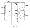
FIG. 6 schematically depicts the system ofFIGS. 1 and2 as an analogous electrical circuit diagram. - In
FIG. 6 , the various components of the system shown inFIGS. 1 and2 are depicted as electrical symbols as known in the art, each labeled with a descriptive word or descriptive abbreviation. The descriptive abbreviations are as follows: - Rvocal_cords refers to the patient's vocal cord resistance. Rvocal_cords is shown as a variable resistor to show the variable resistance generated by the vocal cords (for example, higher pitch sounds generate greater resistance). Rairway refers to the patient's airway resistance. Rtube refers to the patient's circuit tubing resistance or conduit resistance. Ctube refers to the patient's circuit tubing compliance or conduit compliance, which can be measured as a capacitance, or the volume of tubing divided by the pressure in the tubing. Clung refers to the patient's lung compliance. Pmus refers to the pressure created in the patient's lungs by the patient's muscles, and illustrated as an alternating pressure generated by the patient through the patient's muscle action (e.g., patient's diaphragm, intercostal muscles, pectoral muscles, etc.).
- The prefix letter Q refers to a quantity of gas flow delivered by the ventilator (Q_vent) or by the patient during the exhalation phase (Q_exhalation). The Q prefix also refers to a quantity of gas flow delivered (1) to the conduit or tubing system (Q_tube), (2) to the patient (Q_patient), (3) to the patient's lungs (Q_lung) and (4) to the patient's vocal cords (Q_cords).
- As shown in
FIG. 6 , gas flow is delivered by the ventilator (Q_vent) during the inhalation phase of the breathing cycle. Because the exhalation valve is closed (i.e., switch open) during this phase, gas is delivered to the patient (Q_patient) as well as the tubing system (Q_tube). During the inhalation phase, the flow through the vocal cords (Q_cords) is typically zero, as the patient's glottis is closed (represented by the open switch next to Q_cords inFig. 6 ) so the gas (Q_Lung) is delivered to the patient's lungs. However, it should be appreciated that in some instances during the inhalation phase, the gas being delivered by the ventilator can be used for speech purposes by the patients, and so the flow through vocal cords is not zero. - It should be appreciated that the open switch in
FIG. 6 labeled "Exhalation Valve" represents an arrangement wherein the exhalation valve is completely closed for both inhalation and exhalation phases. This switch can be replaced by a variable resistor to reflect arrangements wherein the exhalation valve may be partially or relatively closed during exhalation and/or inhalation phases. - Generally, the exhalation phase of the breathing cycle is when talking is facilitated. Talking is accomplished by increasing the pressure in the lung via the thoracic muscle recoil forces as well as diaphragmatic muscle activity. During speech, the direction of Q_Lung is reversed and leaves the patient through the vocal cords. Modulation of the vocal cords (i.e., vocal cords' resistance variation) is responsible for the cords vibrations which ultimately become speech.
- During the exhalation phase, the ventilator's exhalation valve remains closed (or partially closed), and in this way, the majority of the gas flow is redirected towards the vocal cords during speech. During exhalation, a small amount of gas may flow towards the tubing system compliance. This compliance, typically less than 2 ml/cmH2O, being small compared to the patient Lung compliance (Clung) uses a few milliliters of the gas volume exhaled by the patient.
- The embodiments just described without the speaking valve (check valve) have several advantages, including, but not limited to, the following:
- 1) Allows detection of inflated tracheotomy tube cuffs. This is possible since the ventilator pressure sensors are able to monitor the pressure in the tubing system and this pressure in turn reflects the pressure in the patient's airway and lungs.
- 2) Allows assessment of the patient's airway pressure during exhalation so that stacking of breaths is avoided. This is not practical in embodiments using the speaking valve, since the valve blocks the pneumatic communication with the ventilator's pressure transducers.
- 3) Allows for strong patient coughs without interference from a one way valve's membrane, since no valve is used.
- 4) Allows aerosol treatments without the need to take out the speaking valve.
- 5) Allows suctioning without the need to take out the speaking valve.
- 6) Avoids the need to take out the speaking valve to prevent the valve's disc/membrane from becoming clogged with sputum, since no speaking valve is required.
- Note that embodiments where the speaking valve is present, the volume of gas trapped in the tubing circuit can only escape through the speaking valve. Gas flow through the speaking valve is possible only if there exists a pressure differential across the valve. Thus, monitoring of the pressure in the patient's airway and lungs via monitoring of the tubing system pressure is possible, so long as the pressure in
conduit assembly 32 is greater than or equal to the pressure in the patient's lungs, which is the manner of operation of the present invention. - The present inventor recognized that during the speaking mode, as described above, it is desirable to ensure that the ventilation system operates in a way that remains safe for the user. For example, if the tracheostomy tube's cuff is not deflated or the airway around the tracheostomy tube becomes occluded while in the speaking mode, gas may not be able to leave the patient's lungs. Also disconnection of the patient circuit tube may prevent an effective operation of the ventilator in ventilating the patient. Thus, the present invention seeks to detect occlusions so as to prevent the pressure in the patient's lungs from exceeding a given threshold as well as to prevent asphyxiation, and to detect disconnections or loosing of the components of the ventilator assembly or the endotracheal tube assembly.
- Detecting disconnections or loosing of the components of the ventilator assembly or the endotracheal tube assembly is accomplished by monitoring the pressure of the ventilator circuit at or near the patient (Py). It should be noted that monitoring the pressure can be accomplished by providing a pressure sensor at or near the patient, such as on the wye (Y) connector, or the pressure monitoring can be accomplished by monitoring the pressure in the inhalation and/or exhalation passage. In a further embodiment, the pressure at or near the patient is approximated by measuring the pressure in the ventilator assembly and using conventional techniques to account for the pressure drop in the tubing and/or endotracheal tube assembly, for example by accounting for the pressure drop in the inhalation passage in the case of monitoring pressure in the inspiratory limb or by accounting for the pressure drop in the exhalation passage in the case of monitoring pressure in the expiratory limb.
- While operating in the speaking mode, the exhalation valve remains closed during all phases of ventilation, i.e., during both inhalation and exhalation. In the absence of a disconnect or leak in the tubing circuit, the pressure in the tubing circuit and the patient's airways decays as a function of the level of gas exhaled through the patient's mouth and/or nose. The present inventor recognized that if a disconnect of the patient circuit and/or a significant leak in the patient circuit exists, once the level of gas delivery from the ventilator is cut below a threshold (i.e. 2 lpm), the pressure at the tubing circuit wye decays very fast to a value that is close to zero. More specifically, this rapid pressure decay occurs within the first 100 milliseconds of the initiation the exhalation phase of a breath and remains at this level for the remainder of the exhalation phase. The present invention makes use of this characteristic to detect/declare a circuit disconnect or leak (collectively referred to as a "circuit disconnect").
- The present invention contemplates that the pressure is monitored using
exhalation monitor 58 and the circuit disconnect or leak detection algorithm is implemented bycontroller 52. The total flow of gas provided from the ventilator is monitored by a flow sensor associated with the flow of inspiratory gas, such as a flow sensor disposed in series with the inspiratory circuit withinventilator assembly 14. In a further embodiment, the total flow (Qtot) is based on both the flow of air (Qair) monitored by a first flow sensor, and the flow of a supplemental gas (QO2), such as oxygen, monitored by a second flow sensor over a given period of time. That is, Qtot = Qair + QO2 and is a running average of these flows taken over a period of time, such as 50 msec. Qtot can also be compensated to any given criteria. For example, it is known to compensate the flow to a body temperature pressure saturated (BTPS) flow. - In an exemplary embodiment of the present invention, the system detects or determines when the patient is in the exhalation phase. Once the time elapsed since the start of the exhalation phase (Texh) is greater than a predetermined value, such as 100 msec, and once the total flow Qtot is less than a predetermined amount, such as 2.0 lpm (at least once), the system monitors Py in order to detect whether there is a circuit disconnect or significant leak. In this exemplary embodiment, a peak pressure Ppeak is monitored. In this embodiment the peak pressure Ppeak is a peak value of the average pressure taken over a 50 msec moving window measured during exhalation, is monitored. Again, the identification of the peak value for the pressure starts once 100 msec of exhalation have elapsed and when Qtot < 2 lpm.
- In the exemplary embodiment, a minimum pressure Pmin is also monitored. The minimum pressure Pmin corresponds to a minimum value for the average pressure measured over the 50 msec moving window during exhalation. The identification of this minimum value starts once 100 msec of exhalation have elapsed and when Qtot < 2 lpm at least once.
- In an exemplary embodiment of the present invention, a circuit disconnect is declared if the following conditions exist:
- 1) Ppeak - Pmin < Pthreshold1,
- 2) Ppeak < Pthreshold2
- 3) The patient has not triggered the ventilator, and
- 4a) The pressure at the end of exhalation (Pend_exh) < 1 cmH2O, or
- 4b) The Pend_exh ≤ the pressure at the start of exhalation (Pstart_exh) - a delta pressure.
- Delta pressure is the higher of 1 cmH2O or 50% of Pstart_exh. There are numerous techniques that are used to determine when the patient has triggered the ventilator. For example,
U.S. Patent No. 6,626,175 , teaches several such techniques. If the triggering criteria that are used to determine when the patient has transitioned from exhalation to inhalation are satisfied, the patient is deemed to have triggered the ventilator. It should be noted that triggering the ventilator can also occur automatically, i.e., via internal timing mechanisms without the patient's inspiratory effort. - The circuit disconnect criteria set forth above are provided to ensure that an actual disconnect has occurred. It is to be understood that other embodiments of the present invention do not require that all of these criteria be met. Conversely, still other conditions can be required depending on how aggressive or how reliable the circuit disconnect determination should be.
- To create pressure stability in the tubing circuit, and, thus, allow for the detection of patient tubing disconnections, the present invention contemplates controlling the air and oxygen flow valves, i.e.,
inhalation valve 46, to close in such a manner so as to minimize pressure oscillations in the tubing system that would otherwise be induced by abrupt closure of the gas delivery valves. For example, these valves or valve can be closed using an exponential function trajectory so that they close "gently". - In an exemplary embedment of the present invention, Pthreshold 1 is set at 1.0 cmH2O, and Pthreshold 2 is set at 3.0 cmH2O. It should also be noted that the value for these pressure thresholds need not corresponds to these specific values. The current threshold values are selected so that drift of the flow/pressure sensors does not cause an erroneous circuit disconnect determination.
- The present invention further contemplates that the criteria for a circuit disconnect is tested throughout the entire exhalation phase. In addition, the present invention contemplates that a circuit disconnect will not be declared if a high inspiratory pressure (HIP) condition has occurred, or if an occlusion, as discussed below, has been declared during the breath.
- If a circuit disconnect is detected, a variety of actions can be taken. For example, the ventilator can be programmed to sound a circuit disconnect alarm. The ventilator can also be programmed to continue to deliver ventilated breaths (based on the mode and breath type), at the scheduled times and with the exhalation valve closed during the breath's exhalation phases. The conditions for a circuit disconnect, as noted above, can tested on every breath. If the test proves false, i.e., no circuit disconnect is detected, in a later breath, the circuit disconnect alarm can be discontinued or reset. Of course, a log of the circuit disconnect event can be maintained.
- The present invention contemplates several different techniques for detecting an occlusion of the patient's airway. As noted above, such an occlusion, whether partial or complete, during the speaking mode could adversely impact the ability to implement the speaking mode, the ability to ventilate the patient, and may expose the patient to excessive lung pressures.
- In a first exemplary embodiment, an airway occlusion is declared if a high exhalation pressure condition is continuously detected over a predetermined period of time. For example, if a high exhalation pressure exists for 190 msec consecutively, an occlusion is deemed to exist. In this exemplary embodiment, a high exhalation pressure is defined as a detection of the pressure, as measured by the exhalation pressure sensor, that is higher than the High Inspiratory Pressure (HIP) limit, which is typically set by the caregiver.
- In one embodiment, if a high exhalation pressure condition is detected for 190 milliseconds consecutively, the exhalation valve is opened immediately. The exhalation valve will close again at the start of the next inhalation and ventilation will resume with the exhalation valve closing during inhalations and opening during exhalation phases until the occlusion condition is manually reset by the user. Once the condition is reset, the exhalation valve operation returns to be closed, in both inhalation and exhalation phases, starting at the beginning of the next breath's inhalation.
- It should be noted that the 190 msec period give above is based on the applicable standard (i.e. 60601-2-12 IEC:2001(E); see clauses 50.105 and 50.106 titled Adjustable Pressure Limitation and High Pressure Alarm Condition respectively). Other time periods and high exhalation pressure levels are contemplated by the present invention and can be set or determined based on the needs of the patient or the judgment of the caregiver. The present invention also contemplates that the time period and high exhalation pressure can be adjustable, for example based on the ventilator settings, the condition of the patient, or any other input.
- In a second exemplary embodiment, an airway occlusion is declared based on a comparison of the pressure at the wye with certain occlusion threshold criterion. That is, during the exhalation phase of mandatory breaths (i.e. volume controlled ventilation (VCV) or pressure controlled ventilation (PCV)), while in the speaking mode, the pressure at the wye is compared to occlusion threshold criterion. The comparison starts 100 msec after the reduced flow condition is reached, i.e., Texh > 100 msec and Qtot < 2 lpm at least once during the exhalation phase is met, and continues until the end of the exhalation phase.
- In this embodiment, an airway occlusion is not declared if, during the exhalation phase, Pexh_50 < Poccl for more than 100 msec, consecutively. Pexh_50 corresponds to a 50 millisecond running average of the pressure measurements and is expressed in cmH2O. The occlusion threshold criterion (Poccl), which is also expressed in cmH2O, is calculated, every 5 msec (i.e. every control cycle (n) of the process), as follows:

- Po =
P exh_50 100 msec after Qtot falls below 2 lpm for the first time. - RT = Tauoccl; where, Tauoccl = 0.06 * CL * Roccl (given in seconds),
- CL = Vt / Po = Patient's lung compliance (ml/cmH2O),
- Vt = Volume delivered by the ventilator during the inhalation phase (given in ml),
- Roccl = Po/Qoccl = Equivalent Occlusion Resistance (given in cmH2O/L/min),
- Qoccl = Maximum flow level expected to leave the patient's airway during an airway occlusion. Qoccl is expressed in lpm and is calculated as follows:

- An airway occlusion alarm is declared if Pexh_50 ≥ Poccl for most of the exhalation, and this condition is met for two consecutive breaths. If Pexh_50 ≥ Poccl for most of the exhalation, a second inhalation is started, and, if during this inhalation, the pressure measured in the tubing system reaches a level greater or equal to the HIP Limit minus 1 cmH2O (HIP - 1), the gas delivery system interrupts the gas delivery activity, but the exhalation valve will remain closed for the duration of the next exhalation. If on the second consecutive exhalation, the Pexh_50 ≥ Poccl condition is valid for most of the exhalation, an airway occlusion is declared at the start of the following inhalation. In which case, the exhalation valve is opened and a new exhalation phase is declared. At the end of this additional exhalation phase, the exhalation valve is closed again at the start of the next inhalation, and ventilation resumes with the exhalation valve closing during inhalations and opening during exhalation phases until the occlusion condition is manually reset by the user. Once the condition is reset, the exhalation valve is closed in both inhalation and exhalation phases, starting at the beginning of the next breath's inhalation.
-
FIGS. 7A and 7B are graphs illustrating the occlusion detecting technique of this embodiment.Waveform 100 represents the occlusion threshold criterion Poccl as determined above.Waveform 102 is a state signal indicating the respiratory state of the patient. A high value corresponds to the inspiratory state an a low value corresponds to an expiratory state.Waveform 104 corresponds to Pexh_50. The start of the exhalation is indicated at 108. It can be appreciated that Poccl is a decaying exponential function and begins approximately 100 ms after the exhalation begins. -
FIG. 7A illustrates a situation in where there is no airway occlusion, andFIG. 7B illustrates a situation in which the airway is occluded. InFIG. 7B , it can be appreciated thatP exh_50 104 remains above (greater than) Poccl for most of the duration of the exhalation. The opposite occurs inFIG. 7A . - In a third exemplary embodiment, an airway occlusion is declared based on the maximum flow that is expected to leave the patient while his/hers airway is obstructed. During the exhalation phase of any breath (i.e. while the ventilator is providing VCV, PCV, PSV or CPAP therapy), and while in the speaking mode, the pressure at the wye is used to estimate the maximum flow that is expected to leave the patient while his/hers airway is obstructed. In this embodiment, a critical volume is defined as the volume created by the integration of the maximum flow expected to leave the patient while his/hers airway is obstructed. The critical volume is calculated as follows:


- Qoccl (n) is given in lpm,
- n = control cycle number,
- m = number of exhalation control cycles, and
- To detect an airway occlusion, the estimated flow is integrated and compared to the volume delivered to the patient tubing system on the next inhalation. If the volume delivered on the next inhalation (Vdel_next_breath) to the patient tubing system is less on each of two contiguous breaths, an occlusion of the airway is declared. Vdel_next_breath is defined as follows:

- Qtot(k) = Qair(k) + QO2(k) = Flow delivered by the ventilator for the kth control interval, Qoccl(k) has been defined above,
- k = control cycle number, and
- j = number of inhalation control cycles.
- As explained before, when an airway occlusion is detected, the exhalation valve is opened until the next inhalation is initiated. Ventilation will resume with the exhalation valve closing during inhalations and opening during exhalation phases until the occlusion condition is manually reset by the user. Once the condition is reset, the exhalation valve operation returns to be closed, in both inhalation and exhalation phases, starting at the beginning of the next breath's inhalation. This occlusion detection technique is particularly useful in situations where there are significant fluctuations in the pressure Py, making the other occlusion detection techniques difficult to implement.
- A fourth exemplary embodiment for detecting an airway occlusion is used when the ventilator is operating in a CPAP mode, i.e., the ventilator is not providing mandatory breaths. During the exhalation phase while in CPAP mode and while the speaking mode is implemented, the exhalation valve is opened when the time elapsed since the beginning of the breath is equal to the lesser of an apnea interval minus the inhalation time and
minus 2 seconds or 8 seconds of exhalation time. - The exhaled volume will then be computed by integrating the exhalation flow (as measured by the exhalation flow sensor). A comparison of the exhaled volume (Exhaled_Volume) and the volume delivered by the ventilator during the previous inhalation phase, compensated for the critical volume (Inhaled_Volume-Critical_Volume), is carried out at the beginning of the next inhalation phase. If Exhaled_Volume > 0.5 * (Inhaled_Volume - Critical_Volume) then an airway occlusion is declared. Where:


- Ctube = Patient-Tubing circuit compliance. Given in ml/cmH2O
- Pexh(j) = Tubing circuit pressure measurement, made by the exhalation pressure sensor, on the last control interval cycle for the previous inhalation phase.
- Pexh(m) = Tubing circuit pressure measurement, made by the exhalation pressure sensor, on the last control interval cycle for the current exhalation phase.
- Although the invention has been described in detail for the purpose of illustration based on what is currently considered to be the most practical and preferred embodiments, it is to be understood that such detail is solely for that purpose and that the invention is not limited to the disclosed embodiments, but, on the contrary, is intended to cover modifications and equivalent arrangements that are within the scope of the appended claims. For example, it is to be understood that the present invention contemplates that, to the extent possible, one or more features of any embodiment can be combined with one or more features of any other embodiment.
Claims (7)
- A patient ventilating apparatus (10) comprising:an endotracheal tube (16) constructed and arranged to be installed into a patient's trachea below the patient's vocal cords so that an exterior open end thereof is exterior of the patient and an interior open end thereof communicates with the patient's airway and lungs;a ventilator assembly, comprising:a conduit connected to the exterior open end of the endotracheal tube (16), wherein the conduit includes inhalation and exhalation passages (36, 38) communicating with one another;inhalation and exhalation valves (46, 48) in the inhalation and exhalation passages, respectively;a pressure sensor (54, 58) adapted to monitor a pressure within at least one of the passages during the exhalation phase; anda controller (52) for controlling the inhalation valve and the exhalation valve so as to provide repetitive respiratory cycles, each respiratory cycle including an inhalation phase and an exhalation phase, wherein during the inhalation phase the inhalation valve is open and the exhalation valve is closed and a flow of gas is allowed to pass through the inhalation passage and the tube into the patient's airway and lungs, characterized in that the controller is configured to control the exhalation valve for use in two exhalation phase modes, the two modes including:(1) a first mode wherein the inhalation valve is closed and the exhalation valve is open during the exhalation phase, allowing the gas in the patient's airway and lungs after the preceding inhalation phase to pass through the open exhalation valve and through an outlet of the ventilator assembly, and(2) a second mode wherein the inhalation valve is closed and the exhalation valve is closed so that the patient causes the gas in the patient's airway and lungs after the preceding inhalation phase to flow passed the patient's vocal cords and out of the patient's mouth, thus facilitating the patient's ability to talk, and wherein the controller is adapted to determine whether a disconnect of a patient circuit or an occlusion exists based on the monitored pressure, wherein the endotracheal tube has a check valve (64) in the exterior open end thereof.
- The patient ventilating apparatus of claim 1, wherein the controller comprises an exhalation controller module (44) that controls the exhalation valve and an inhalation controller module (42) that controls the inhalation valve.
- The patient ventilating apparatus of claim 1, wherein the controller comprises a first algorithm for controlling the inhalation valve, a second algorithm for controlling the exhalation valve, and a third for determining whether the disconnect of a patient circuit or the occlusion exists.
- The patient ventilating apparatus of claim 1, wherein the exhalation valve is controlled by the controller to be closed sufficiently during the inhalation phase to enable a desired pressure to build within the conduit.
- The patient ventilating apparatus of claim 1, wherein the exhalation valve is controlled by the controller to be closed sufficiently during the exhalation phase to maintain a desired pressure in the conduit.
- The patient ventilation apparatus of claim 1, wherein the controller determines whether the disconnect of a patient circuit exists by determining a peak pressure during the exhalation phase, and comparing the peak pressure to a first threshold.
- The patient ventilating apparatus of claim 1, wherein the controller determines whether the disconnect of a patient circuit exits by:determining a minimum pressure during the exhalation phase;determining a delta pressure as a difference between the minimum pressure and the peak pressure; andcomparing the delta pressure to a second threshold.
Applications Claiming Priority (3)
| Application Number | Priority Date | Filing Date | Title |
|---|---|---|---|
| US11/518,816 US7997272B2 (en) | 2006-09-11 | 2006-09-11 | Ventilating apparatus and method enabling a patient to talk with or without a trachostomy tube check valve |
| US11/893,796 US8161972B2 (en) | 2006-09-11 | 2007-08-17 | Detecting ventilator system anomalies while in a speaking mode |
| PCT/US2007/077902 WO2008033730A2 (en) | 2006-09-11 | 2007-09-07 | Detecting ventilator system anomalies while in a speaking mode |
Publications (3)
| Publication Number | Publication Date |
|---|---|
| EP2066412A2 EP2066412A2 (en) | 2009-06-10 |
| EP2066412A4 EP2066412A4 (en) | 2014-11-05 |
| EP2066412B1 true EP2066412B1 (en) | 2016-11-16 |
Family
ID=39168329
Family Applications (2)
| Application Number | Title | Priority Date | Filing Date |
|---|---|---|---|
| EP07842073.4A Active EP2066384B1 (en) | 2006-09-11 | 2007-09-07 | Ventilating apparatus enabling a patient to talk with or without a trachostomy tube check valve |
| EP07842070.0A Active EP2066412B1 (en) | 2006-09-11 | 2007-09-07 | Detecting ventilator system anomalies while in a speaking mode |
Family Applications Before (1)
| Application Number | Title | Priority Date | Filing Date |
|---|---|---|---|
| EP07842073.4A Active EP2066384B1 (en) | 2006-09-11 | 2007-09-07 | Ventilating apparatus enabling a patient to talk with or without a trachostomy tube check valve |
Country Status (7)
| Country | Link |
|---|---|
| US (3) | US7997272B2 (en) |
| EP (2) | EP2066384B1 (en) |
| JP (2) | JP5264733B2 (en) |
| CN (2) | CN101553268B (en) |
| BR (2) | BRPI0716568A2 (en) |
| RU (2) | RU2455031C2 (en) |
| WO (1) | WO2008033732A2 (en) |
Families Citing this family (109)
| Publication number | Priority date | Publication date | Assignee | Title |
|---|---|---|---|---|
| US7588033B2 (en) | 2003-06-18 | 2009-09-15 | Breathe Technologies, Inc. | Methods, systems and devices for improving ventilation in a lung area |
| FR2858236B1 (en) * | 2003-07-29 | 2006-04-28 | Airox | DEVICE AND METHOD FOR SUPPLYING RESPIRATORY GAS IN PRESSURE OR VOLUME |
| JP2007506480A (en) | 2003-08-18 | 2007-03-22 | ワンドカ,アンソニー・ディ | Methods and apparatus for non-invasive ventilation with a nasal interface |
| US8496006B2 (en) | 2005-01-20 | 2013-07-30 | Pulmonx Corporation | Methods and devices for passive residual lung volume reduction and functional lung volume expansion |
| US20080228137A1 (en) | 2007-03-12 | 2008-09-18 | Pulmonx | Methods and devices for passive residual lung volume reduction and functional lung volume expansion |
| US11883029B2 (en) | 2005-01-20 | 2024-01-30 | Pulmonx Corporation | Methods and devices for passive residual lung volume reduction and functional lung volume expansion |
| EP1926517A2 (en) | 2005-09-20 | 2008-06-04 | Lutz Freitag | Systems, methods and apparatus for respiratory support of a patient |
| US8518024B2 (en) | 2006-04-24 | 2013-08-27 | Transenterix, Inc. | System and method for multi-instrument surgical access using a single access port |
| JP5191005B2 (en) | 2006-05-18 | 2013-04-24 | ブリーズ テクノロジーズ, インコーポレイテッド | Method and device for tracheostomy |
| EP2068992B1 (en) | 2006-08-03 | 2016-10-05 | Breathe Technologies, Inc. | Devices for minimally invasive respiratory support |
| US7997272B2 (en) * | 2006-09-11 | 2011-08-16 | Ric Investments, Llc. | Ventilating apparatus and method enabling a patient to talk with or without a trachostomy tube check valve |
| WO2008144589A1 (en) | 2007-05-18 | 2008-11-27 | Breathe Technologies, Inc. | Methods and devices for sensing respiration and providing ventilation therapy |
| US8567399B2 (en) | 2007-09-26 | 2013-10-29 | Breathe Technologies, Inc. | Methods and devices for providing inspiratory and expiratory flow relief during ventilation therapy |
| JP5513392B2 (en) | 2007-09-26 | 2014-06-04 | ブリーズ・テクノロジーズ・インコーポレーテッド | Method and apparatus for treating sleep apnea |
| US9199049B2 (en) * | 2007-10-24 | 2015-12-01 | Jeffrey A Attwood | Expiratory volume reservoir for a ventilator patient circuit |
| CN101468219B (en) * | 2007-12-28 | 2012-10-31 | 北京谊安医疗系统股份有限公司 | Gas path system and operation method thereof as well as breathing apparatus and anesthesia apparatus using the system |
| JP5758799B2 (en) | 2008-04-18 | 2015-08-05 | ブリーズ・テクノロジーズ・インコーポレーテッド | Method and device for sensing respiratory effects and controlling ventilator function |
| US8770193B2 (en) | 2008-04-18 | 2014-07-08 | Breathe Technologies, Inc. | Methods and devices for sensing respiration and controlling ventilator functions |
| US8251876B2 (en) | 2008-04-22 | 2012-08-28 | Hill-Rom Services, Inc. | Breathing exercise apparatus |
| US8752546B2 (en) * | 2008-04-23 | 2014-06-17 | General Electric Company | System and method for mobilizing occlusions from a breathing tube |
| US8457706B2 (en) * | 2008-05-16 | 2013-06-04 | Covidien Lp | Estimation of a physiological parameter using a neural network |
| US8925549B2 (en) * | 2008-08-11 | 2015-01-06 | Surge Ingenuity Corporation | Flow control adapter for performing spirometry and pulmonary function testing |
| CA2734296C (en) | 2008-08-22 | 2018-12-18 | Breathe Technologies, Inc. | Methods and devices for providing mechanical ventilation with an open airway interface |
| US8302602B2 (en) | 2008-09-30 | 2012-11-06 | Nellcor Puritan Bennett Llc | Breathing assistance system with multiple pressure sensors |
| CA2739435A1 (en) | 2008-10-01 | 2010-04-08 | Breathe Technologies, Inc. | Ventilator with biofeedback monitoring and control for improving patient activity and health |
| US9132250B2 (en) | 2009-09-03 | 2015-09-15 | Breathe Technologies, Inc. | Methods, systems and devices for non-invasive ventilation including a non-sealing ventilation interface with an entrainment port and/or pressure feature |
| WO2010115170A2 (en) * | 2009-04-02 | 2010-10-07 | Breathe Technologies, Inc. | Methods, systems and devices for non-invasive open ventilation for treating airway obstructions |
| US8434479B2 (en) * | 2009-02-27 | 2013-05-07 | Covidien Lp | Flow rate compensation for transient thermal response of hot-wire anemometers |
| US20100218766A1 (en) * | 2009-02-27 | 2010-09-02 | Nellcor Puritan Bennett Llc | Customizable mandatory/spontaneous closed loop mode selection |
| US9962512B2 (en) | 2009-04-02 | 2018-05-08 | Breathe Technologies, Inc. | Methods, systems and devices for non-invasive ventilation including a non-sealing ventilation interface with a free space nozzle feature |
| FR2945217B1 (en) * | 2009-05-07 | 2012-09-21 | Assist Publ Hopitaux De Paris | PHONATION ASSISTANCE DEVICE FOR A TRACHEOTOMISED PATIENT. |
| CA2774902C (en) * | 2009-09-03 | 2017-01-03 | Breathe Technologies, Inc. | Methods, systems and devices for non-invasive ventilation including a non-sealing ventilation interface with an entrainment port and/or pressure feature |
| US8439037B2 (en) * | 2009-12-01 | 2013-05-14 | Covidien Lp | Exhalation valve assembly with integrated filter and flow sensor |
| US20110126832A1 (en) * | 2009-12-01 | 2011-06-02 | Nellcor Puritan Bennett Llc | Exhalation Valve Assembly |
| US8439036B2 (en) | 2009-12-01 | 2013-05-14 | Covidien Lp | Exhalation valve assembly with integral flow sensor |
| US8469031B2 (en) | 2009-12-01 | 2013-06-25 | Covidien Lp | Exhalation valve assembly with integrated filter |
| US8469030B2 (en) | 2009-12-01 | 2013-06-25 | Covidien Lp | Exhalation valve assembly with selectable contagious/non-contagious latch |
| JP5759481B2 (en) * | 2010-01-14 | 2015-08-05 | コーニンクレッカ フィリップス エヌ ヴェ | Auxiliary ventilator with negative pressure support |
| USD655809S1 (en) | 2010-04-27 | 2012-03-13 | Nellcor Puritan Bennett Llc | Valve body with integral flow meter for an exhalation module |
| USD653749S1 (en) | 2010-04-27 | 2012-02-07 | Nellcor Puritan Bennett Llc | Exhalation module filter body |
| USD655405S1 (en) | 2010-04-27 | 2012-03-06 | Nellcor Puritan Bennett Llc | Filter and valve body for an exhalation module |
| US9901695B2 (en) * | 2010-06-22 | 2018-02-27 | Koninklijke Philips N.V. | Respiratory interface apparatus |
| US9968750B2 (en) * | 2010-06-30 | 2018-05-15 | St. Michael's Hospital | Method and system for patient-synchronized ventilatory assist with endotracheal through-flow |
| JP5891226B2 (en) | 2010-08-16 | 2016-03-22 | ブリーズ・テクノロジーズ・インコーポレーテッド | Method, system and apparatus for providing ventilatory assistance using LOX |
| US9370633B2 (en) | 2010-09-10 | 2016-06-21 | Carefusion 207, Inc. | Nasal intermittent mandatory ventilation (NIMV) control system in a ventilator |
| WO2012045051A1 (en) | 2010-09-30 | 2012-04-05 | Breathe Technologies, Inc. | Methods, systems and devices for humidifying a respiratory tract |
| WO2012085787A2 (en) * | 2010-12-21 | 2012-06-28 | Koninklijke Philips Electronics N.V. | System and method for inexsufflating a subject |
| US9629971B2 (en) | 2011-04-29 | 2017-04-25 | Covidien Lp | Methods and systems for exhalation control and trajectory optimization |
| US20120272962A1 (en) * | 2011-04-29 | 2012-11-01 | Nellcor Puritan Bennett Llc | Methods and systems for managing a ventilator patient with a capnometer |
| EP3808399B1 (en) * | 2011-09-13 | 2024-02-21 | ResMed Pty Ltd | Vent arrangement for respiratory mask |
| US9364624B2 (en) | 2011-12-07 | 2016-06-14 | Covidien Lp | Methods and systems for adaptive base flow |
| US9498589B2 (en) | 2011-12-31 | 2016-11-22 | Covidien Lp | Methods and systems for adaptive base flow and leak compensation |
| US9022031B2 (en) | 2012-01-31 | 2015-05-05 | Covidien Lp | Using estimated carinal pressure for feedback control of carinal pressure during ventilation |
| US9180271B2 (en) | 2012-03-05 | 2015-11-10 | Hill-Rom Services Pte. Ltd. | Respiratory therapy device having standard and oscillatory PEP with nebulizer |
| US9327089B2 (en) | 2012-03-30 | 2016-05-03 | Covidien Lp | Methods and systems for compensation of tubing related loss effects |
| US8844526B2 (en) | 2012-03-30 | 2014-09-30 | Covidien Lp | Methods and systems for triggering with unknown base flow |
| US9144658B2 (en) | 2012-04-30 | 2015-09-29 | Covidien Lp | Minimizing imposed expiratory resistance of mechanical ventilator by optimizing exhalation valve control |
| NZ705875A (en) * | 2012-08-22 | 2017-09-29 | Resmed Paris Sas | Breathing assistance system with speech detection |
| US10076619B2 (en) | 2012-09-11 | 2018-09-18 | Resmed Limited | Vent arrangement for respiratory mask |
| GB201222684D0 (en) * | 2012-12-15 | 2013-01-30 | Smiths Medical Int Ltd | Medico-surgical apparatus |
| US9492629B2 (en) | 2013-02-14 | 2016-11-15 | Covidien Lp | Methods and systems for ventilation with unknown exhalation flow and exhalation pressure |
| USD731049S1 (en) | 2013-03-05 | 2015-06-02 | Covidien Lp | EVQ housing of an exhalation module |
| USD693001S1 (en) | 2013-03-08 | 2013-11-05 | Covidien Lp | Neonate expiratory filter assembly of an exhalation module |
| USD701601S1 (en) | 2013-03-08 | 2014-03-25 | Covidien Lp | Condensate vial of an exhalation module |
| USD692556S1 (en) | 2013-03-08 | 2013-10-29 | Covidien Lp | Expiratory filter body of an exhalation module |
| DE102013004115A1 (en) * | 2013-03-08 | 2014-09-11 | Universitätsmedizin Der Johannes Gutenberg-Universität Mainz | TRACHEAL CANNULA AND SPEAKING VENTILATION SYSTEM FOR MACHINE VENTILATION |
| USD731048S1 (en) | 2013-03-08 | 2015-06-02 | Covidien Lp | EVQ diaphragm of an exhalation module |
| USD731065S1 (en) | 2013-03-08 | 2015-06-02 | Covidien Lp | EVQ pressure sensor filter of an exhalation module |
| USD736905S1 (en) | 2013-03-08 | 2015-08-18 | Covidien Lp | Exhalation module EVQ housing |
| USD744095S1 (en) | 2013-03-08 | 2015-11-24 | Covidien Lp | Exhalation module EVQ internal flow sensor |
| US9981096B2 (en) | 2013-03-13 | 2018-05-29 | Covidien Lp | Methods and systems for triggering with unknown inspiratory flow |
| US9950135B2 (en) | 2013-03-15 | 2018-04-24 | Covidien Lp | Maintaining an exhalation valve sensor assembly |
| US9839761B1 (en) | 2013-07-04 | 2017-12-12 | Hal Rucker | Airflow control for pressurized air delivery |
| US9925348B2 (en) | 2013-07-17 | 2018-03-27 | Upods, Llc | Gas delivery device |
| US9440039B2 (en) | 2013-07-17 | 2016-09-13 | Upods, Llc | Gas delivery device |
| DE202014000155U1 (en) * | 2013-12-24 | 2015-03-26 | Ac Aircontrols Gmbh | System for providing a gas for the ventilation of a patient |
| EP3086831B1 (en) * | 2013-12-27 | 2020-09-23 | St. Michael's Hospital | System for providing ventilatory assist to a patient |
| US9757532B2 (en) * | 2014-02-14 | 2017-09-12 | Breathe Technologies, Inc. | Detection of patient interface disconnect for controlling continuous positive airway pressure therapy |
| US9808591B2 (en) | 2014-08-15 | 2017-11-07 | Covidien Lp | Methods and systems for breath delivery synchronization |
| US11285287B2 (en) | 2014-09-30 | 2022-03-29 | Frank H. Arlinghaus, Jr. | Tracheostomy or endotracheal tube adapter for speech |
| US10532171B2 (en) | 2014-09-30 | 2020-01-14 | Frank H. Arlinghaus, Jr. | Tracheostomy or endotracheal tube adapter for speech |
| US9950129B2 (en) | 2014-10-27 | 2018-04-24 | Covidien Lp | Ventilation triggering using change-point detection |
| WO2016108127A1 (en) * | 2014-12-30 | 2016-07-07 | Koninklijke Philips N.V. | Capnometry system with supplemental oxygen detection and method of operation thereof |
| US9925346B2 (en) | 2015-01-20 | 2018-03-27 | Covidien Lp | Systems and methods for ventilation with unknown exhalation flow |
| JP6480598B2 (en) | 2015-04-02 | 2019-03-13 | ヒル−ロム サービシーズ プライヴェート リミテッド | Respirator manifold |
| USD775345S1 (en) | 2015-04-10 | 2016-12-27 | Covidien Lp | Ventilator console |
| GB2540024A (en) * | 2015-06-11 | 2017-01-04 | Smiths Medical Int Ltd | Ventilator systems and controls |
| US10765822B2 (en) | 2016-04-18 | 2020-09-08 | Covidien Lp | Endotracheal tube extubation detection |
| CN106492317B (en) * | 2016-11-25 | 2019-06-14 | 钟春兰 | A kind of medical atomized drug delivery device |
| US11311689B2 (en) * | 2017-02-20 | 2022-04-26 | Weinmann Emergency Medical Technology Gmbh & Co. Kg | Breathing apparatus comprising a differential pressure sensor |
| CN107569753B (en) * | 2017-08-22 | 2021-02-19 | 天津怡和嘉业医疗科技有限公司 | Breathing pipeline, breathing machine and sensor data transmission method |
| US10792449B2 (en) | 2017-10-03 | 2020-10-06 | Breathe Technologies, Inc. | Patient interface with integrated jet pump |
| DE102017009603A1 (en) * | 2017-10-13 | 2019-04-18 | Drägerwerk AG & Co. KGaA | Device for ventilating a patient |
| CN109939311A (en) * | 2017-12-20 | 2019-06-28 | 北京谊安医疗系统股份有限公司 | The judgment method and ventilator of breathing circuit obstruction block warning device |
| DE102018003026A1 (en) * | 2018-04-13 | 2019-10-17 | Drägerwerk AG & Co. KGaA | Ventilation device with a safety valve |
| CN109172986A (en) * | 2018-10-15 | 2019-01-11 | 福建中医药大学附属人民医院(福建省人民医院) | A kind of auxiliary sounding device and bionical vocal technique |
| CN109758153B (en) * | 2019-01-30 | 2024-04-02 | 上海长征医院 | Full nasal cavity air pressure detection equipment and application method thereof |
| GB2581999B (en) * | 2019-03-07 | 2023-01-04 | Bpr Medical Ltd | Gas flow alarm |
| US11324954B2 (en) | 2019-06-28 | 2022-05-10 | Covidien Lp | Achieving smooth breathing by modified bilateral phrenic nerve pacing |
| WO2021034172A1 (en) * | 2019-08-16 | 2021-02-25 | 고려대학교 산학협력단 | Bidirectional flow-controllable artificial respirator |
| KR102470057B1 (en) * | 2019-08-16 | 2022-11-23 | 고려대학교 산학협력단 | bidirectional flow controllable ventilator |
| US11896767B2 (en) | 2020-03-20 | 2024-02-13 | Covidien Lp | Model-driven system integration in medical ventilators |
| CN111536277B (en) * | 2020-06-17 | 2022-04-08 | 中国建筑设计研究院有限公司 | Drainage non-return system and drainage non-return method |
| RU201954U1 (en) * | 2020-10-07 | 2021-01-22 | Общество с ограниченной ответственностью (ООО) "АЛЬТОНИКА" | Electronic monitoring and control device of artificial lung ventilation apparatus |
| RU201157U1 (en) * | 2020-10-27 | 2020-12-01 | Общество с ограниченной ответственностью (ООО) "АЛЬТОНИКА" | Electronic control and remote control device for artificial lung ventilation apparatus |
| WO2022133657A1 (en) * | 2020-12-21 | 2022-06-30 | 深圳麦科田生物医疗技术股份有限公司 | Breathing assembly supporting voice function and ventilation method thereof, and breathing machine |
| DE102022118009A1 (en) * | 2021-08-07 | 2023-02-09 | Löwenstein Medical Technology S.A. | VENTILATION SYSTEM WITH VOICE FUNCTION |
| WO2023148794A1 (en) * | 2022-02-03 | 2023-08-10 | Universita' Degli Studi Di Firenze | Device for maintaining peep in a patient, and mechanical ventilation circuit comprising said device |
| WO2024052339A1 (en) * | 2022-09-07 | 2024-03-14 | Ben Fabry | Ventilator and method for controlling a ventilator |
Family Cites Families (29)
| Publication number | Priority date | Publication date | Assignee | Title |
|---|---|---|---|---|
| US4219020A (en) | 1978-08-09 | 1980-08-26 | Fraser Sweatman, Inc. | Scavenger valve attachment for inhalation sedation system mask |
| US4280492A (en) * | 1979-10-05 | 1981-07-28 | Latham Phillip B | Tracheostomy tube |
| US4442856A (en) | 1981-08-18 | 1984-04-17 | Puritan-Bennett | Oxygen regulator and alarm system for an anesthesia machine |
| US4538607A (en) * | 1984-02-06 | 1985-09-03 | Ab Fixfabriken | Tracheostomy valve |
| DE3422066A1 (en) * | 1984-06-14 | 1985-12-19 | Drägerwerk AG, 2400 Lübeck | VENTILATION SYSTEM AND CONTROLLABLE VALVE UNIT TO |
| DE3672719D1 (en) * | 1985-03-08 | 1990-08-23 | Passy & Passy Inc | ARRANGEMENT FOR TRACHEOTOMY. |
| JPS61232842A (en) * | 1985-04-08 | 1986-10-17 | チエスト株式会社 | Sounding apparatus |
| US4593689A (en) * | 1985-04-15 | 1986-06-10 | White Kenneth S | Endotracheal tube including means for patient communication |
| US5813399A (en) | 1993-03-16 | 1998-09-29 | Puritan Bennett Corporation | System and method for closed loop airway pressure control during the inspiratory cycle of a breath in a patient ventilator using the exhalation valve as a microcomputer-controlled relief valve |
| US5392775A (en) * | 1994-03-22 | 1995-02-28 | Adkins, Jr.; Claude N. | Duckbill valve for a tracheostomy tube that permits speech |
| GB9411215D0 (en) * | 1994-06-04 | 1994-07-27 | Brain Archibald Ian Jeremy | A fibreoptic intubating laryngeal mask airway |
| US5881717A (en) | 1997-03-14 | 1999-03-16 | Nellcor Puritan Bennett Incorporated | System and method for adjustable disconnection sensitivity for disconnection and occlusion detection in a patient ventilator |
| US6543449B1 (en) | 1997-09-19 | 2003-04-08 | Respironics, Inc. | Medical ventilator |
| GB2318518B (en) * | 1997-12-10 | 1998-09-09 | Falah Hasan Ali | Micro ventilation anaesthetic circuit |
| US6722367B1 (en) * | 1997-12-22 | 2004-04-20 | Hansa Medical Products, Inc. | Valved fenestrated tracheotomy tube having outer and inner cannulae |
| US6189534B1 (en) * | 1998-10-13 | 2001-02-20 | Mallinckrodt Inc. | Bi-functional in-line phonation valve |
| US6230708B1 (en) * | 1998-10-30 | 2001-05-15 | Sechrist Industries, Inc. | Ventilator triggering device |
| US6334441B1 (en) * | 1998-11-23 | 2002-01-01 | Mallinckrodt Medical, Inc. | Phonation valve for breathing tube |
| DE59906763D1 (en) * | 1999-02-01 | 2003-10-02 | Adeva Medical Ges Fuer Entwick | tracheal stoma |
| US6401713B1 (en) * | 1999-05-05 | 2002-06-11 | Respironics, Inc. | Apparatus and method of providing continuous positive airway pressure |
| US6626175B2 (en) | 2000-10-06 | 2003-09-30 | Respironics, Inc. | Medical ventilator triggering and cycling method and mechanism |
| US6588428B2 (en) * | 2001-02-23 | 2003-07-08 | Adam Spence Corp. | Speaking valve for a tracheostomy tube |
| US6725862B2 (en) * | 2001-08-24 | 2004-04-27 | Naum Klinberg | Tracheostomy tube apparatus for noninvasive suctioning |
| JP2003210585A (en) * | 2002-01-21 | 2003-07-29 | Hiroaki Nomori | Tracheotomic tube |
| AU2003297942B2 (en) | 2002-12-16 | 2009-01-08 | Rutter, Dr Michael J. | Tracheotomy valve unit |
| AU2004224573B2 (en) | 2003-03-24 | 2010-07-08 | Resmed Paris | Breathing assistance apparatus |
| FR2852853B1 (en) * | 2003-03-24 | 2006-12-29 | Saime Sarl | DEVICE FOR AIDING BREATHING |
| US7617824B2 (en) * | 2005-12-08 | 2009-11-17 | Ric Investments, Llc | Ventilator adaptable for use with either a dual-limb circuit or a single-limb circuit |
| US7997272B2 (en) * | 2006-09-11 | 2011-08-16 | Ric Investments, Llc. | Ventilating apparatus and method enabling a patient to talk with or without a trachostomy tube check valve |
-
2006
- 2006-09-11 US US11/518,816 patent/US7997272B2/en active Active
-
2007
- 2007-08-17 US US11/893,796 patent/US8161972B2/en active Active
- 2007-09-07 JP JP2009527588A patent/JP5264733B2/en not_active Expired - Fee Related
- 2007-09-07 EP EP07842073.4A patent/EP2066384B1/en active Active
- 2007-09-07 RU RU2009113599/14A patent/RU2455031C2/en active
- 2007-09-07 JP JP2009527589A patent/JP5184534B2/en active Active
- 2007-09-07 WO PCT/US2007/077906 patent/WO2008033732A2/en active Application Filing
- 2007-09-07 BR BRPI0716568-4A patent/BRPI0716568A2/en not_active Application Discontinuation
- 2007-09-07 RU RU2009113536/14A patent/RU2455030C2/en active
- 2007-09-07 CN CN2007800335126A patent/CN101553268B/en active Active
- 2007-09-07 BR BRPI0716567-6A patent/BRPI0716567A2/en not_active IP Right Cessation
- 2007-09-07 CN CN2007800335037A patent/CN101553284B/en active Active
- 2007-09-07 EP EP07842070.0A patent/EP2066412B1/en active Active
-
2011
- 2011-07-01 US US13/174,859 patent/US20110259339A1/en not_active Abandoned
Non-Patent Citations (1)
| Title |
|---|
| None * |
Also Published As
| Publication number | Publication date |
|---|---|
| JP5264733B2 (en) | 2013-08-14 |
| CN101553284B (en) | 2013-07-31 |
| JP2010502401A (en) | 2010-01-28 |
| US20080060646A1 (en) | 2008-03-13 |
| RU2009113599A (en) | 2010-10-20 |
| US8161972B2 (en) | 2012-04-24 |
| BRPI0716568A2 (en) | 2013-11-05 |
| WO2008033732A3 (en) | 2008-06-12 |
| RU2009113536A (en) | 2010-10-20 |
| CN101553268B (en) | 2013-03-06 |
| EP2066384A2 (en) | 2009-06-10 |
| EP2066412A4 (en) | 2014-11-05 |
| US20080060656A1 (en) | 2008-03-13 |
| BRPI0716567A2 (en) | 2013-10-15 |
| JP2010502402A (en) | 2010-01-28 |
| EP2066384B1 (en) | 2018-12-19 |
| WO2008033732A2 (en) | 2008-03-20 |
| CN101553284A (en) | 2009-10-07 |
| RU2455030C2 (en) | 2012-07-10 |
| JP5184534B2 (en) | 2013-04-17 |
| EP2066384A4 (en) | 2014-11-05 |
| CN101553268A (en) | 2009-10-07 |
| RU2455031C2 (en) | 2012-07-10 |
| US7997272B2 (en) | 2011-08-16 |
| US20110259339A1 (en) | 2011-10-27 |
| EP2066412A2 (en) | 2009-06-10 |
Similar Documents
| Publication | Publication Date | Title |
|---|---|---|
| EP2066412B1 (en) | Detecting ventilator system anomalies while in a speaking mode | |
| JP2010502401A5 (en) | ||
| US6626175B2 (en) | Medical ventilator triggering and cycling method and mechanism | |
| CA2036184C (en) | System and method for flow triggering of pressure supported ventilation | |
| EP2401015B1 (en) | Pressure support system with machine delivered breaths | |
| JP5802559B2 (en) | Detection of patient-ventilator dyssynchrony | |
| JP2010502402A5 (en) | ||
| AU2002211468A1 (en) | Medical ventilator triggering and cycling method and mechanism | |
| US9272111B2 (en) | Leak estimation using function estimation | |
| WO2008033730A2 (en) | Detecting ventilator system anomalies while in a speaking mode |
Legal Events
| Date | Code | Title | Description |
|---|---|---|---|
| PUAI | Public reference made under article 153(3) epc to a published international application that has entered the european phase |
Free format text: ORIGINAL CODE: 0009012 |
|
| AK | Designated contracting states |
Kind code of ref document: A2 Designated state(s): AT BE BG CH CY CZ DE DK EE ES FI FR GB GR HU IE IS IT LI LT LU LV MC MT NL PL PT RO SE SI SK TR |
|
| AX | Request for extension of the european patent |
Extension state: AL BA HR MK RS |
|
| 17P | Request for examination filed |
Effective date: 20090414 |
|
| R17D | Deferred search report published (corrected) |
Effective date: 20080508 |
|
| RBV | Designated contracting states (corrected) |
Designated state(s): AT BE BG CH CY CZ DE DK EE ES FI FR GB GR HU IE IS IT LI LT LU LV MC MT NL PL PT RO SE SI SK TR |
|
| DAX | Request for extension of the european patent (deleted) | ||
| A4 | Supplementary search report drawn up and despatched |
Effective date: 20141009 |
|
| RIC1 | Information provided on ipc code assigned before grant |
Ipc: A61M 16/00 20060101ALI20141002BHEP Ipc: A61M 5/168 20060101ALI20141002BHEP Ipc: A61M 16/04 20060101ALI20141002BHEP Ipc: A62B 9/02 20060101AFI20141002BHEP Ipc: A61M 39/10 20060101ALI20141002BHEP |
|
| 17Q | First examination report despatched |
Effective date: 20151110 |
|
| GRAJ | Information related to disapproval of communication of intention to grant by the applicant or resumption of examination proceedings by the epo deleted |
Free format text: ORIGINAL CODE: EPIDOSDIGR1 |
|
| GRAP | Despatch of communication of intention to grant a patent |
Free format text: ORIGINAL CODE: EPIDOSNIGR1 |
|
| INTG | Intention to grant announced |
Effective date: 20160615 |
|
| GRAS | Grant fee paid |
Free format text: ORIGINAL CODE: EPIDOSNIGR3 |
|
| GRAA | (expected) grant |
Free format text: ORIGINAL CODE: 0009210 |
|
| AK | Designated contracting states |
Kind code of ref document: B1 Designated state(s): AT BE BG CH CY CZ DE DK EE ES FI FR GB GR HU IE IS IT LI LT LU LV MC MT NL PL PT RO SE SI SK TR |
|
| REG | Reference to a national code |
Ref country code: GB Ref legal event code: FG4D |
|
| REG | Reference to a national code |
Ref country code: CH Ref legal event code: EP |
|
| REG | Reference to a national code |
Ref country code: IE Ref legal event code: FG4D |
|
| REG | Reference to a national code |
Ref country code: AT Ref legal event code: REF Ref document number: 845362 Country of ref document: AT Kind code of ref document: T Effective date: 20161215 |
|
| REG | Reference to a national code |
Ref country code: DE Ref legal event code: R096 Ref document number: 602007048809 Country of ref document: DE |
|
| PG25 | Lapsed in a contracting state [announced via postgrant information from national office to epo] |
Ref country code: LV Free format text: LAPSE BECAUSE OF FAILURE TO SUBMIT A TRANSLATION OF THE DESCRIPTION OR TO PAY THE FEE WITHIN THE PRESCRIBED TIME-LIMIT Effective date: 20161116 |
|
| REG | Reference to a national code |
Ref country code: NL Ref legal event code: MP Effective date: 20161116 |
|
| REG | Reference to a national code |
Ref country code: LT Ref legal event code: MG4D |
|
| REG | Reference to a national code |
Ref country code: AT Ref legal event code: MK05 Ref document number: 845362 Country of ref document: AT Kind code of ref document: T Effective date: 20161116 |
|
| PG25 | Lapsed in a contracting state [announced via postgrant information from national office to epo] |
Ref country code: NL Free format text: LAPSE BECAUSE OF FAILURE TO SUBMIT A TRANSLATION OF THE DESCRIPTION OR TO PAY THE FEE WITHIN THE PRESCRIBED TIME-LIMIT Effective date: 20161116 Ref country code: GR Free format text: LAPSE BECAUSE OF FAILURE TO SUBMIT A TRANSLATION OF THE DESCRIPTION OR TO PAY THE FEE WITHIN THE PRESCRIBED TIME-LIMIT Effective date: 20170217 Ref country code: LT Free format text: LAPSE BECAUSE OF FAILURE TO SUBMIT A TRANSLATION OF THE DESCRIPTION OR TO PAY THE FEE WITHIN THE PRESCRIBED TIME-LIMIT Effective date: 20161116 Ref country code: SE Free format text: LAPSE BECAUSE OF FAILURE TO SUBMIT A TRANSLATION OF THE DESCRIPTION OR TO PAY THE FEE WITHIN THE PRESCRIBED TIME-LIMIT Effective date: 20161116 |
|
| PG25 | Lapsed in a contracting state [announced via postgrant information from national office to epo] |
Ref country code: FI Free format text: LAPSE BECAUSE OF FAILURE TO SUBMIT A TRANSLATION OF THE DESCRIPTION OR TO PAY THE FEE WITHIN THE PRESCRIBED TIME-LIMIT Effective date: 20161116 Ref country code: PL Free format text: LAPSE BECAUSE OF FAILURE TO SUBMIT A TRANSLATION OF THE DESCRIPTION OR TO PAY THE FEE WITHIN THE PRESCRIBED TIME-LIMIT Effective date: 20161116 Ref country code: ES Free format text: LAPSE BECAUSE OF FAILURE TO SUBMIT A TRANSLATION OF THE DESCRIPTION OR TO PAY THE FEE WITHIN THE PRESCRIBED TIME-LIMIT Effective date: 20161116 Ref country code: PT Free format text: LAPSE BECAUSE OF FAILURE TO SUBMIT A TRANSLATION OF THE DESCRIPTION OR TO PAY THE FEE WITHIN THE PRESCRIBED TIME-LIMIT Effective date: 20170316 Ref country code: AT Free format text: LAPSE BECAUSE OF FAILURE TO SUBMIT A TRANSLATION OF THE DESCRIPTION OR TO PAY THE FEE WITHIN THE PRESCRIBED TIME-LIMIT Effective date: 20161116 |
|
| PG25 | Lapsed in a contracting state [announced via postgrant information from national office to epo] |
Ref country code: SK Free format text: LAPSE BECAUSE OF FAILURE TO SUBMIT A TRANSLATION OF THE DESCRIPTION OR TO PAY THE FEE WITHIN THE PRESCRIBED TIME-LIMIT Effective date: 20161116 Ref country code: DK Free format text: LAPSE BECAUSE OF FAILURE TO SUBMIT A TRANSLATION OF THE DESCRIPTION OR TO PAY THE FEE WITHIN THE PRESCRIBED TIME-LIMIT Effective date: 20161116 Ref country code: CZ Free format text: LAPSE BECAUSE OF FAILURE TO SUBMIT A TRANSLATION OF THE DESCRIPTION OR TO PAY THE FEE WITHIN THE PRESCRIBED TIME-LIMIT Effective date: 20161116 Ref country code: EE Free format text: LAPSE BECAUSE OF FAILURE TO SUBMIT A TRANSLATION OF THE DESCRIPTION OR TO PAY THE FEE WITHIN THE PRESCRIBED TIME-LIMIT Effective date: 20161116 Ref country code: RO Free format text: LAPSE BECAUSE OF FAILURE TO SUBMIT A TRANSLATION OF THE DESCRIPTION OR TO PAY THE FEE WITHIN THE PRESCRIBED TIME-LIMIT Effective date: 20161116 |
|
| REG | Reference to a national code |
Ref country code: DE Ref legal event code: R097 Ref document number: 602007048809 Country of ref document: DE |
|
| PG25 | Lapsed in a contracting state [announced via postgrant information from national office to epo] |
Ref country code: IT Free format text: LAPSE BECAUSE OF FAILURE TO SUBMIT A TRANSLATION OF THE DESCRIPTION OR TO PAY THE FEE WITHIN THE PRESCRIBED TIME-LIMIT Effective date: 20161116 Ref country code: BG Free format text: LAPSE BECAUSE OF FAILURE TO SUBMIT A TRANSLATION OF THE DESCRIPTION OR TO PAY THE FEE WITHIN THE PRESCRIBED TIME-LIMIT Effective date: 20170216 Ref country code: BE Free format text: LAPSE BECAUSE OF FAILURE TO SUBMIT A TRANSLATION OF THE DESCRIPTION OR TO PAY THE FEE WITHIN THE PRESCRIBED TIME-LIMIT Effective date: 20161116 |
|
| PLBE | No opposition filed within time limit |
Free format text: ORIGINAL CODE: 0009261 |
|
| STAA | Information on the status of an ep patent application or granted ep patent |
Free format text: STATUS: NO OPPOSITION FILED WITHIN TIME LIMIT |
|
| REG | Reference to a national code |
Ref country code: FR Ref legal event code: PLFP Year of fee payment: 11 |
|
| 26N | No opposition filed |
Effective date: 20170817 |
|
| PG25 | Lapsed in a contracting state [announced via postgrant information from national office to epo] |
Ref country code: SI Free format text: LAPSE BECAUSE OF FAILURE TO SUBMIT A TRANSLATION OF THE DESCRIPTION OR TO PAY THE FEE WITHIN THE PRESCRIBED TIME-LIMIT Effective date: 20161116 |
|
| REG | Reference to a national code |
Ref country code: CH Ref legal event code: PL |
|
| PG25 | Lapsed in a contracting state [announced via postgrant information from national office to epo] |
Ref country code: MC Free format text: LAPSE BECAUSE OF FAILURE TO SUBMIT A TRANSLATION OF THE DESCRIPTION OR TO PAY THE FEE WITHIN THE PRESCRIBED TIME-LIMIT Effective date: 20161116 |
|
| REG | Reference to a national code |
Ref country code: IE Ref legal event code: MM4A |
|
| PG25 | Lapsed in a contracting state [announced via postgrant information from national office to epo] |
Ref country code: LU Free format text: LAPSE BECAUSE OF NON-PAYMENT OF DUE FEES Effective date: 20170907 |
|
| PG25 | Lapsed in a contracting state [announced via postgrant information from national office to epo] |
Ref country code: IE Free format text: LAPSE BECAUSE OF NON-PAYMENT OF DUE FEES Effective date: 20170907 Ref country code: CH Free format text: LAPSE BECAUSE OF NON-PAYMENT OF DUE FEES Effective date: 20170930 Ref country code: LI Free format text: LAPSE BECAUSE OF NON-PAYMENT OF DUE FEES Effective date: 20170930 |
|
| REG | Reference to a national code |
Ref country code: FR Ref legal event code: PLFP Year of fee payment: 12 |
|
| PG25 | Lapsed in a contracting state [announced via postgrant information from national office to epo] |
Ref country code: MT Free format text: LAPSE BECAUSE OF NON-PAYMENT OF DUE FEES Effective date: 20170907 |
|
| PG25 | Lapsed in a contracting state [announced via postgrant information from national office to epo] |
Ref country code: HU Free format text: LAPSE BECAUSE OF FAILURE TO SUBMIT A TRANSLATION OF THE DESCRIPTION OR TO PAY THE FEE WITHIN THE PRESCRIBED TIME-LIMIT; INVALID AB INITIO Effective date: 20070907 |
|
| PG25 | Lapsed in a contracting state [announced via postgrant information from national office to epo] |
Ref country code: CY Free format text: LAPSE BECAUSE OF NON-PAYMENT OF DUE FEES Effective date: 20161116 |
|
| PG25 | Lapsed in a contracting state [announced via postgrant information from national office to epo] |
Ref country code: TR Free format text: LAPSE BECAUSE OF FAILURE TO SUBMIT A TRANSLATION OF THE DESCRIPTION OR TO PAY THE FEE WITHIN THE PRESCRIBED TIME-LIMIT Effective date: 20161116 |
|
| PG25 | Lapsed in a contracting state [announced via postgrant information from national office to epo] |
Ref country code: IS Free format text: LAPSE BECAUSE OF FAILURE TO SUBMIT A TRANSLATION OF THE DESCRIPTION OR TO PAY THE FEE WITHIN THE PRESCRIBED TIME-LIMIT Effective date: 20170316 |
|
| REG | Reference to a national code |
Ref country code: DE Ref legal event code: R081 Ref document number: 602007048809 Country of ref document: DE Owner name: PHILIPS RS NORTH AMERICA LLC, PITTSBURGH, US Free format text: FORMER OWNER: RIC INVESTMENTS, LLC, WILMINGTON, DEL., US Ref country code: DE Ref legal event code: R082 Ref document number: 602007048809 Country of ref document: DE |
|
| PGFP | Annual fee paid to national office [announced via postgrant information from national office to epo] |
Ref country code: FR Payment date: 20220926 Year of fee payment: 16 |
|
| REG | Reference to a national code |
Ref country code: GB Ref legal event code: 732E Free format text: REGISTERED BETWEEN 20230323 AND 20230329 |
|
| PGFP | Annual fee paid to national office [announced via postgrant information from national office to epo] |
Ref country code: GB Payment date: 20230926 Year of fee payment: 17 |
|
| PGFP | Annual fee paid to national office [announced via postgrant information from national office to epo] |
Ref country code: DE Payment date: 20230928 Year of fee payment: 17 |