EP2068733B1 - Percutaneous instrument assembly - Google Patents
Percutaneous instrument assembly Download PDFInfo
- Publication number
- EP2068733B1 EP2068733B1 EP07838822.0A EP07838822A EP2068733B1 EP 2068733 B1 EP2068733 B1 EP 2068733B1 EP 07838822 A EP07838822 A EP 07838822A EP 2068733 B1 EP2068733 B1 EP 2068733B1
- Authority
- EP
- European Patent Office
- Prior art keywords
- tower
- elongated member
- percutaneous
- channel
- connecting element
- Prior art date
- Legal status (The legal status is an assumption and is not a legal conclusion. Google has not performed a legal analysis and makes no representation as to the accuracy of the status listed.)
- Not-in-force
Links
Images


Classifications
-
- A—HUMAN NECESSITIES
- A61—MEDICAL OR VETERINARY SCIENCE; HYGIENE
- A61B—DIAGNOSIS; SURGERY; IDENTIFICATION
- A61B17/00—Surgical instruments, devices or methods, e.g. tourniquets
- A61B17/56—Surgical instruments or methods for treatment of bones or joints; Devices specially adapted therefor
- A61B17/58—Surgical instruments or methods for treatment of bones or joints; Devices specially adapted therefor for osteosynthesis, e.g. bone plates, screws, setting implements or the like
- A61B17/68—Internal fixation devices, including fasteners and spinal fixators, even if a part thereof projects from the skin
- A61B17/70—Spinal positioners or stabilisers ; Bone stabilisers comprising fluid filler in an implant
- A61B17/7074—Tools specially adapted for spinal fixation operations other than for bone removal or filler handling
- A61B17/7076—Tools specially adapted for spinal fixation operations other than for bone removal or filler handling for driving, positioning or assembling spinal clamps or bone anchors specially adapted for spinal fixation
- A61B17/7077—Tools specially adapted for spinal fixation operations other than for bone removal or filler handling for driving, positioning or assembling spinal clamps or bone anchors specially adapted for spinal fixation for moving bone anchors attached to vertebrae, thereby displacing the vertebrae
- A61B17/708—Tools specially adapted for spinal fixation operations other than for bone removal or filler handling for driving, positioning or assembling spinal clamps or bone anchors specially adapted for spinal fixation for moving bone anchors attached to vertebrae, thereby displacing the vertebrae with tubular extensions coaxially mounted on the bone anchors
-
- A—HUMAN NECESSITIES
- A61—MEDICAL OR VETERINARY SCIENCE; HYGIENE
- A61B—DIAGNOSIS; SURGERY; IDENTIFICATION
- A61B17/00—Surgical instruments, devices or methods, e.g. tourniquets
- A61B17/56—Surgical instruments or methods for treatment of bones or joints; Devices specially adapted therefor
- A61B17/58—Surgical instruments or methods for treatment of bones or joints; Devices specially adapted therefor for osteosynthesis, e.g. bone plates, screws, setting implements or the like
- A61B17/68—Internal fixation devices, including fasteners and spinal fixators, even if a part thereof projects from the skin
- A61B17/70—Spinal positioners or stabilisers ; Bone stabilisers comprising fluid filler in an implant
- A61B17/7074—Tools specially adapted for spinal fixation operations other than for bone removal or filler handling
- A61B17/7076—Tools specially adapted for spinal fixation operations other than for bone removal or filler handling for driving, positioning or assembling spinal clamps or bone anchors specially adapted for spinal fixation
-
- A—HUMAN NECESSITIES
- A61—MEDICAL OR VETERINARY SCIENCE; HYGIENE
- A61B—DIAGNOSIS; SURGERY; IDENTIFICATION
- A61B17/00—Surgical instruments, devices or methods, e.g. tourniquets
- A61B17/56—Surgical instruments or methods for treatment of bones or joints; Devices specially adapted therefor
- A61B17/58—Surgical instruments or methods for treatment of bones or joints; Devices specially adapted therefor for osteosynthesis, e.g. bone plates, screws, setting implements or the like
- A61B17/68—Internal fixation devices, including fasteners and spinal fixators, even if a part thereof projects from the skin
- A61B17/70—Spinal positioners or stabilisers ; Bone stabilisers comprising fluid filler in an implant
- A61B17/7074—Tools specially adapted for spinal fixation operations other than for bone removal or filler handling
- A61B17/7083—Tools for guidance or insertion of tethers, rod-to-anchor connectors, rod-to-rod connectors, or longitudinal elements
- A61B17/7085—Tools for guidance or insertion of tethers, rod-to-anchor connectors, rod-to-rod connectors, or longitudinal elements for insertion of a longitudinal element down one or more hollow screw or hook extensions, i.e. at least a part of the element within an extension has a component of movement parallel to the extension's axis
-
- A—HUMAN NECESSITIES
- A61—MEDICAL OR VETERINARY SCIENCE; HYGIENE
- A61B—DIAGNOSIS; SURGERY; IDENTIFICATION
- A61B17/00—Surgical instruments, devices or methods, e.g. tourniquets
- A61B17/56—Surgical instruments or methods for treatment of bones or joints; Devices specially adapted therefor
- A61B17/58—Surgical instruments or methods for treatment of bones or joints; Devices specially adapted therefor for osteosynthesis, e.g. bone plates, screws, setting implements or the like
- A61B17/68—Internal fixation devices, including fasteners and spinal fixators, even if a part thereof projects from the skin
- A61B17/70—Spinal positioners or stabilisers ; Bone stabilisers comprising fluid filler in an implant
- A61B17/7001—Screws or hooks combined with longitudinal elements which do not contact vertebrae
- A61B17/7002—Longitudinal elements, e.g. rods
- A61B17/7011—Longitudinal element being non-straight, e.g. curved, angled or branched
-
- A—HUMAN NECESSITIES
- A61—MEDICAL OR VETERINARY SCIENCE; HYGIENE
- A61B—DIAGNOSIS; SURGERY; IDENTIFICATION
- A61B17/00—Surgical instruments, devices or methods, e.g. tourniquets
- A61B17/56—Surgical instruments or methods for treatment of bones or joints; Devices specially adapted therefor
- A61B17/58—Surgical instruments or methods for treatment of bones or joints; Devices specially adapted therefor for osteosynthesis, e.g. bone plates, screws, setting implements or the like
- A61B17/68—Internal fixation devices, including fasteners and spinal fixators, even if a part thereof projects from the skin
- A61B17/70—Spinal positioners or stabilisers ; Bone stabilisers comprising fluid filler in an implant
- A61B17/7001—Screws or hooks combined with longitudinal elements which do not contact vertebrae
- A61B17/7032—Screws or hooks with U-shaped head or back through which longitudinal rods pass
Description
- Various stabilization devices and associated methods are known for securing various bones, such as vertebrae of the spine, relative to one another. Such devices include, for example, pedicle screws or other fasteners attached to the vertebrae, connecting elements passing through receivers formed on the pedicle screws, and various instruments for inserting the pedicle screws and mounting the connecting elements on the receivers.
-
US 2005/071540 discloses an instrument for minimally invasive spinal stabilization provided for introducing flexible stabilization element and securing the flexible stabilization element to one or more anchors. - Continuing concern with reducing trauma, infection risk, and patient recovery time, encourages the development of instruments that may help reduce the invasiveness of the procedure. The present teachings provide such a percutaneous instrument assembly and associated methods not claimed for spinal procedures.
- The present invention relates to a percutaneous tower for the orthopedic procedures as claimed hereafter. Preferred embodiments of the invention are set forth in the dependent claims.
- The present teachings provide a percutaneous tower for the orthopedic procedures. The tower can include an outer elongated member, an inner elongated member received within the outer elongated member, means for moving the inner elongated member relative to the outer elongated member between first and second positions, and means for engaging a bone fastener when the inner elongated member is in the first position.
- In another aspect according to the present teachings, a percutaneous tower for the orthopedic procedures can include an outer elongated member, an inner elongated member received within the outer elongated member, a release actuator operable to move the inner elongated member relative to the outer elongated member between first and second positions, and a fastener engagement member coupled to a distal portion of the tower and operable to engage a bone fastener when the inner elongated member is in the first position, and to disengage the bone fastener when the inner elongated member is in the second position.
- In another aspect according to the present teachings, a percutaneous tower for the orthopedic procedures can include an outer elongated member, an inner elongated member received within the outer elongated member, and a release actuator operable to move the inner elongated member relative to the outer elongated member between first and second positions, the inner elongated member at least partially retracted relative to the outer elongated member in first position, the inner elongated member at least partially extended relative to the outer elongated member in the second position, the release actuator communicating with a proximal portion of a first channel of the tower, and a locking element couplable to the tower and operable to lock the release the release actuator in the first position.
- In a further aspect according to the present teachings, a percutaneous tower for the orthopedic procedures can include an outer elongated member, an inner elongated member received within the outer elongated member, a pair of release members operable to move the inner elongated member relative to the outer elongated member between first and second positions, and a pair of opposing elements coupled to a distal portion of the inner elongated member, the elements biased to protrude away from the inner elongated member when the inner elongated member is in the second position, each element including a protrusion directed into the tower when the inner elongated member is in the first position.
- The present teachings also provide a method, not claimed, for percutaneously implanting a spinal connecting element. The method can include implanting a first bone fastener through a first portal into a first vertebral body, and implanting a second fastener through a second portal into a second vertebral body. The method can further include inserting a connecting element through the first portal in a first orientation substantially perpendicular to the first vertebral body, rotating the connecting element relative to the first orientation such that the connecting element is positioned between the first and second bone fasteners in a second orientation at an angle to the first orientation, and securing the connecting element between the first and a second bone fasteners in the second orientation.
- In another aspect, the present teachings provide a method, not claimed for percutaneously implanting a spinal connecting element. The method can include attaching a first bone fastener to a distal portion of a first channel of a first tower, the first channel defining a first longitudinal axis, the first longitudinal axis passing longitudinally through the first bone fastener, and implanting the first bone fastener into a first vertebral body. The method, not claimed, can further include attaching a second bone fastener to a first channel of a distal portion of a second tower, implanting the second bone fastener into a second vertebral body, inserting the connecting element through a second channel of the first tower, the second channel of the first tower defining a second longitudinal axis substantially parallel to the first longitudinal axis of the first tower and offset in a transverse direction relative to the first longitudinal axis of the first tower, and selectively manipulating the connecting element along a variable-angle path from a position substantially aligned with the second longitudinal axis of the first tower to a position between the first and second bone fasteners.
- The present teachings further provide a method, not claimed, of manipulating a first vertebral body relative to a second vertebral body. The method can include engaging a first vertebral body with a first bone fastener connected to a first tower, engaging a second vertebral body with a second bone fastener connected to a second tower, coupling proximal ends of the first and second towers with a compression/distraction mechanism, locking with the compression/distraction mechanism the first and second bone fasteners against accidental release from the first and second towers, operating the compression/distraction mechanism, and moving the first and second towers relative to one another.
- Further areas of applicability of the present invention will become apparent from the description provided hereinafter. It should be understood that the description and specific examples are intended for purposes of illustration only and are not intended to limit the scope of the invention.
- The present invention will become more fully understood from the detailed description and the accompanying drawings, wherein:
-
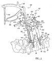
FIG. 1 is a perspective view of an exemplary percutaneous instrument assembly according to the present teachings shown in reference with two adjacent vertebrae; -
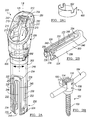
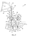
FIG. 2A is a perspective view of an exemplary percutaneous tower according to the present teachings, shown with a locking element; -
FIG. 2A1 is a perspective view of the locking element ofFIG. 2A ; -
FIG. 2B is a perspective view of a distal portion of the percutaneous tower ofFIG. 2A ; -
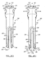
FIG. 2C1 is a perspective view of the percutaneous tower ofFIG. 2A shown in a retracted position; -
FIG. 2D1 is a perspective view of the percutaneous tower ofFIG. 2A shown in a extended position; -
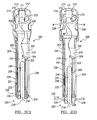
FIG. 2C2 is a partially cut-out view of the percutaneous tower ofFIG. 2C1 ; -
FIG. 2D2 is a partially cut-out view of the percutaneous tower ofFIG. 2D1 ; -
FIG. 2E is a perspective view of an exemplary outer elongated member of the percutaneous tower ofFIG. 2A ; -
FIG. 2F is a perspective view of an exemplary inner elongated member of the percutaneous tower ofFIG. 2A ; -
FIG. 2G is a perspective view of an exemplary flexible or pivotable bar of the percutaneous tower ofFIG. 2A ; -
FIG. 2H is a perspective view of an exemplary bone fastener shown with a connecting element according to the present teachings; -
FIG. 2I is an exploded view of the percutaneous tower ofFIG. 2A ; -
FIG. 3A is a top view of the percutaneous tower ofFIG. 2A , shown with a channel divider in a closed position; -
FIG. 3B is a top view of the percutaneous tower ofFIG. 2A , shown with a channel divider in an open position; -
FIG. 3C is a top view of the percutaneous tower ofFIG. 2A shown with a tower connector of a compression/distraction mechanism according to the present teachings; -
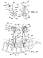
FIG. 4A is a partially exploded perspective view of an exemplary percutaneous instrument assembly according to the present teachings shown with two exemplary percutaneous towers and an exemplary compression-distraction mechanism; -
FIG. 4B is an exploded view of an exemplary compression-distraction mechanism according to the present teachings; -
FIG. 5A a top view of an exemplary percutaneous instrument assembly according to the present teachings shown with two exemplary percutaneous towers and an exemplary compression/distraction mechanism; -
FIG. 5B is a side view of an exemplary percutaneous instrument assembly according to the present teachings illustrating an exemplary compression/distraction mechanism relative to vertebral bodies; -
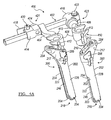
FIG. 6A is a top view of a portion of a percutaneous rod inserter before engaging or after releasing a connecting element according to the present teachings; -
FIG. 6B is a side view of a percutaneous rod inserter shown in engagement with a connecting element according to the present teachings; -
FIG. 7A is plan view of a connecting element according to the present teachings; -
FIG. 7B is a side view of the connecting element ofFIG. 7A ; -
FIG. 8A is plan view of a percutaneous rod inserter shown with locking arms in engagement with a connecting element according to the present teachings; -
FIG. 8B is a plan view of a percutaneous rod inserter shown with locking arms disengaged from a connecting element according to the present teachings; -
FIG. 8C is a side view of the percutaneous rod inserter and connecting element ofFIG. 8A ; -
FIG. 8D is a side view of the percutaneous rod inserter and connecting element ofFIG. 8A , with the connecting element shown in an angled position; -
FIG. 9A is an exploded view of an exemplary percutaneous rod inserter according to the present teachings; -
FIG. 9B is a perspective view of the percutaneous rod inserter ofFIG. 9A shown with a connecting element in a first position; -
FIG. 9C is a perspective view of the percutaneous rod inserter ofFIG. 9A shown with a connecting element in a second angled position; -
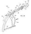
FIG. 10 is a side view of an exemplary percutaneous instrument assembly according to the present teachings illustrating a percutaneous rod inserter guiding a connecting element through a channel of a percutaneous tower connected to a vertebral body; -
FIG. 11 is an exploded view of an exemplary fastener inserter according to the present teachings; -
FIG. 11A is perspective view of the fastener inserter ofFIG. 11 shown assembled through a percutaneous tower according to the present teachings; and -
FIG. 12 is an environmental view of a connecting element and two bone fasteners implanted in a spine according to the present teachings. - The following description is merely exemplary in nature and is in no way intended to limit the invention, its application, or uses. For example, although the present teachings are illustrated for minimally invasive procedures in spinal fusion, or static or dynamic stabilization, the present teachings can be used for other orthopedic surgical applications in which various implants and instruments are manipulated and aligned through a limited area.
- Referring to
FIG. 1 , an exemplarypercutaneous instrument assembly 100 according to the present teachings can generally include one or morepercutaneous towers 200, a percutaneous rod or connectingelement inserter 300, and a compression/distraction mechanism 400. It will be appreciated that various other instruments, such as tissue separators, drills, distractors, cannulas, guide wires, bone or pedicle screw inserters, or other instruments can be used in association with thepercutaneous instrument assembly 100 at the discretion of the operating surgeon. - As illustrated in
FIG. 1 , thepercutaneous instrument assembly 100 can be used as a spine hardware delivery system that can provide a minimally invasive approach for spine fusion procedures, static or dynamic spine stabilization, or other orthopedic procedures. Thepercutaneous towers 200 of thepercutaneous instrument assembly 100 can be used to implant or remove bone or pedicle screws, bone anchors, orother bone fasteners 102 into thevertebral bodies 80 of the spine. Thepercutaneous towers 200 can also be used to advance a percutaneous connectingelement 104, such as a connecting rod or bar or other elongated element, using thepercutaneous rod inserter 300. - As a preparatory matter, utilizing anterior/posterior and lateral fluoroscopic imaging and palpation of the patient's appropriate vertebral landmarks, the targeted pedicles can be located and marked on the patient's skin. A percutaneous skin incision and fascia release in the form of a small portal can be made with a knife blade, a Jamshidi-type needle, or other cutting instrument at the location marks on the patient's skin and a needle or similar instrument can be advanced through the skin incision. The needle can be docked onto the targeted pedicle and verified with fluoroscopic imaging. Once trajectory and docking of the needle is confirmed and complete, the needle can be removed and replaced by guide wire.
- Dilation of the opening of the incision through the muscles can be performed, for example, in a two-staged sequential manner over the guide wire. A cannulated tap can be advanced over the guide wire and the pedicle can be prepared for the implantation of a cannulated bone anchor, such as the
bone fastener 102. Thebone fastener 102 can then be assembled onto the distal end of thepercutaneous tower 200. - Referring to
FIGS. 2A-3B , eachpercutaneous tower 200 can include an outer elongated member orouter shaft 202 and an inner elongated member orinner shaft 204. The outer and innerelongated members fastener engagement member 230 that can be used to secure thebone fastener 102 to thepercutaneous tower 200 without requiring additional locks or manipulating steps. Referring toFIGS. 2D1 and2D2 , quick disconnection can be effected through manual depression of a release actuator feature of thetower 200 in the direction of arrows "A". In this regard, one ormore release buttons 206 can be simultaneously depressed, thereby allowing thebone fastener 102 to be released, as described below. Therelease buttons 206 are pivotably coupled to the proximal portions of the outerelongated member 202, such that the innerelongated member 204 can move relative to the outerelongated member 202 from a first "retracted" position shown inFIGS. 2C1 and2C2 in which thefastener engagement member 230 is in an engagement configuration relative to thebone fastener 102, to a second "extended" position, shown inFIGS. 2D1 and2D2 downwardly translated in the direction of arrow "B", in which thefastener engagement member 230 is in a disengagement configuration relative to thebone fastener 102. - Referring to
FIGS. 2A and 2A1 , the percutaneous tower can include alocking element 600 for locking therelease buttons 206 and preventing their accidental depression. The lockingelement 600 can be in the form of a split ring or other U-shaped element. The lockingelement 600 can be fitted over the outerelongated member 202 as shown inFIG. 2A . The lockingelement 600 can include two pockets, cutouts orother openings 602. Theopenings 602 can be configured to allow pivoting of therelease buttons 206 in the unlocked position. For example, the distal ends of therelease buttons 206 can swing outward relative to thetower 200 through theopenings 602 of thelocking element 600 in the unlocked position of thelocking element 600. The lockingelement 600 can be rotated from the unlocked position to a locked position in which therelease buttons 206 can be prevented from pivoting, such that the distal ends of therelease buttons 206 can be prevented from swinging out relatively to thetower 200. - Referring to
FIGS. 2A-D2 ,2G and2H , thefastener engagement member 230 can include two elements in the form of one or more flexible (elastically deflectable) orpivotable bars 232 that can engage respective opposingslots 208 of the innerelongated member 204. Thebars 232 can be held between the outer and innerelongated members bar 232 can include atab 234 and aprotrusion 236 at opposite ends of itsdistal end 231. When the innerelongated member 204 is in the retracted position shown inFIGS. 2B ,2C1 and2C2 , thetabs 234 are held inwards by the outerelongated member 202, such that theprotrusions 236 extend transversely into a first longitudinal opening, hole orchannel 210, which extends along a first longitudinal axis L1 of thetower 200. As shown through the drawings, the longitudinal axis L1 of thetower 200 can pass through the proximal portion of the associatedbone fastener 102. - In the retracted position of the inner
elongated member 204, theprotrusions 236 can engagecorresponding engagement slots 108 in areceiver portion 106 of thebone fastener 102, shown inFIG. 2H , as described below. When the innerelongated member 204 is in the extended position shown inFIGS. 2D1 and2D2 , thetabs 234 move outwards in the direction of arrows "C" protruding out of theslots 208 of the innerelongated member 204 and becoming disengaged from theengagement slots 108 of thereceiver portion 106 of thebone fastener 102. It will be appreciated that thebone fastener 102 can be held by either the outerelongated member 202 or the innerelongated member 204 at the distal end of thetower 200. - Each
tower 200 can at least partially define or include thefirst channel 210 discussed above and asecond channel 212 which extends along a second axis L2. Thefirst channel 210 can extend from acurved opening 214 at aproximal end 215 of the outerelongated member 202 through acommon bore 216 of the outer and innerelongated members opening 218 at adistal end 220 of thetower 200. Thesecond channel 212 can communicate with thefirst channel 210. Thesecond channel 212 can be offset from thefirst channel 210 in a direction transverse to the first axis L1 such that the axes L1 and L2 are parallel, but not coinciding. Thesecond channel 212 is formed in anangled portion 217 of theproximal end 215 and includes an offsetopening 213, which can extend from thecurved opening 214 in a U-shape form. It another aspect, thesecond channel 212 can be angled and such that the second axis L2 coincides with the first axis L1. - The first and
second channels distal portion 301 of thepercutaneous rod inserter 300, the connectingelement 104, as shown inFIGS. 1 and10 ,tower connectors 408 of the compression/distraction mechanism 400, abone fastener inserter 500, as shown inFIG. 11A , and other instruments and implants, as discussed below. - Referring to
FIGS. 2A ,2I , and3A-C , a spring-loadedchannel divider 250 can be coupled to theproximal end 215 of the outerelongated member 202. As discussed below, thechannel divider 250 can function to selectively and optionally separate the first andsecond channels 210,212The channel divider 250 can include a base 254 slidably coupled to theproximal end 215, and twoarms 252 pivotably coupled to thebase 254. The base 254 can be moved between first and second positions as shown inFIGS. 3A and B . In the first position, shown inFIG. 3A , thearms 252 are forced closer to each other, such that end portions of thearms 252 extend between the first andsecond channels second channels FIG. 3B , thearms 252 spring outwards away from the openings of the first andsecond channels second channels - Referring
FIGS. 2A ,2E ,2F and4A , eachtower 200 can also have first and secondlongitudinal slots second slots elongated member 202 and first andsecond slots elongated member 204. Referring toFIG. 4A , thefirst slot 221 can be longer and can be placed on the side of theangled portion 217 of thetower 200 to provide additional space for instrumentation. Thesecond slot 223 can be shorter and can be placed opposite thefirst slot 221 for guiding the connectingelement 104 as it exits or enters one of thetowers 200. The first andsecond slots elongated member 202 define first and second opposinglegs elongated member 202. Similarly, the first andsecond slots elongated member 204 define first and second opposinglegs elongated member 204. - Referring to
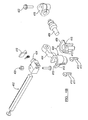
FIGS. 4A-5B , an exemplary compression-distraction (C/D)mechanism 400 adapted for use with thetowers 200 is illustrated. The C/D mechanism 400 can include a dial-typelinear control 421 and a dial-typerotational control 423. Thelinear control 421 can adjust the distance between thepercutaneous towers 200, and therotational control 423 can adjust the angle of thetowers 200 relative to each other and to the patient. Thelinear control 421 of the C/D mechanism 400 can also determine the distance between thepercutaneous towers 200, and therefore it can be used to determine the length of the connectingelement 104 that is required for a particular surgical procedure. In this regard, the C/D mechanism 400 can be provided with indicia representative of a distance between the associatedbone fasteners 102. When thetower connectors 200 are not aligned in parallel, a mathematical formula based on the geometric relation and the relative angles of thetowers 200 can be used to determine the appropriate length of the connectingelement 104. - The C/
D mechanism 400 can include arack 402 and first andsecond arms arms tower connector 408. In the exemplary illustration of the C/D mechanism 400, thefirst arm 404 can slide along therack 402 in the direction of the straight arrows "T". Thesecond arm 406 can be fixed relative to therack 402 and can rotate about its axis "A1" such that thetower connector 408 that is attached to thesecond arm 406 can angulate relative to therack 402 and relative to thetower connector 408 that is connected to thefirst arm 404 in the directions shown by the curved arrows "R" inFIG. 5B . Eachtower connector 408 can be configured to be received in the proximal portion of thetower 200 and can include first andsecond channels second channels tower 200 enabling the instruments and implants to pass freely through both devices. - Each
tower connector 408 can include akey feature 409, which is configured to complement theangled portion 217 of theproximal end 215 of thetower 200. Thekey feature 409 prevents rotation of thetower connector 408 relative to thetower 200 and allows coupling in only one direction. Thetower connector 408 can also include a quick-connect, button-style mechanism 412 having atab 411 that can engage aninternal groove 205 of therelease button 206 of the tower 200 (shown inFIG. 2I ). When thetower connector 408 is attached to thetower 200, thetower connector 408 can act as a safety lock, similarly to thelocking element 600, pushing against the inner surfaces of therelease buttons 206 and preventing activation of therelease buttons 206, thereby preventing accidental release of thebone fastener 102 from thetower 200. - Referring to
FIGS. 4A ,5A, and 5B , the C/D mechanism 400 can include adirectional lock 424, which can be a knob with first and second settings. In the first setting, thefirst arm 404 can be moved along therack 402 bringing the first andsecond arms tower connectors 408 closer to one another for compression. In the second setting, thefirst arm 404 can be moved along therack 402 to position the first andsecond arms tower connectors 408 further apart relative to one another for distraction. When one of the first and second settings of thedirectional lock 424 is selected, thefirst arm 404 can slide along therack 402 in the selected direction by turning aposition control knob 420. Alock release control 418 can be provided and operate to incapacitate thedirectional lock 424, such that thefirst arm 404 is free to move in either direction for compression or distraction. - Referring to
FIGS. 5A and B , the C/D mechanism 400 can include anangulation control 422 which can be rotated to rotate thesecond arm 406 about its axis A1 causing therespective tower 200 to angulate in the direction of the arrows R towards or away from thetower 200 that is coupled to thefirst arm 404, as illustrated inFIG. 5B . - Referring to
FIGS. 6A-10 , thepercutaneous rod inserter 300 is illustrated in exemplary positions relative to the connectingelement 104. Therod inserter 300 can include a rongeur-type body 302 including arack bar 310, anangle handle 308 that can be coupled to various positions along therack bar 310, arelease trigger 306, and an elongateddistal portion 301 insertable through the first 210 orsecond channel 212 of thetower 200. The elongateddistal portion 301 can include mechanisms for releasably coupling the connectingelement 104 to therod inserter 300, such that the connectingelement 104 can be held in a first position in which a longitudinal axis "E" of the connectingelement 104 is substantially parallel or coaxial to a longitudinal axis "D" of the elongateddistal portion 301 of therod inserter 300, as shown inFIGS. 8C and9B , and in a second position in which the connectingelement 104 is at an angle α relative to the elongateddistal portion 301 of the rod inserter, as shown inFIGS. 8D and9C . - The angle handle 308 can be operably coupled to an
angle arm 304 that can include a U-shapeddistal portion 312 adapted to pivotable engage anopen slot 142 in the proximal end of the connectingelement 104. Pressing the angle handle 308 in the direction of arrow "G2" causes theangle arm 304 to move forward in the direction of arrow "H2" and urges the connectingelement 104 to pivot at an angled position relative to the elongateddistal portion 301 of thepercutaneous rod inserter 300, as shown inFIGS. 9C and8D . Conversely, pushing the angle handle 308 in the direction of arrow "G1" urges theangle arm 304 to move backward in the direction of arrow "H1" forcing the connectingelement 104 to straighten out along the elongateddistal portion 301 of therod inserter 300, as shown inFIGS. 9B and8C . It will be appreciated that the direction of motion associated with arrows H1, H2 and G1, G2 can be reversed. - The
release trigger 306 can be operably coupled to ashaft 316 coupled to a pair ofpivotable locking arms 314, shown inFIGS. 8A, 8B and9A . The lockingarms 314 can be biased to remain in the close position illustrated inFIG. 9B , and can be pivoted to an open position by pressing therelease trigger 306 in the direction of arrow "K", as shown inFIG. 9C . The lockingarms 314 can be L-shaped and haveend portions 315 that can pass through ahole 144 defined in aproximal end 140 of the connectingelement 104 when the lockingarms 314 are in their closed position, as shown inFIG. 8A and9B . Asafety lock 318 can be placed in the lock position indicated by arrow "I1" inFIG. 9B , to ensure that the lockingarms 314 remain closed and the connectingelement 104 is not released prematurely before it is properly positioned between thebone fasteners 102 as shown inFIG 12 . The connectingelement 104 can be released from therod inserter 300 by placing thesafety lock 318 in the open position indicated by arrow "I2" inFIG. 9C , and pulling therelease trigger 306 in the direction of the arrow K. While holding the lockingarms 314 in the open position, thedistal portion 312 of theangle arm 304 can be pushed out of theslot 142 of the connectingelement 104. - Referring to
FIGS. 7A and B , the connectingelement 104 can include ashaft 146 having a bullet-like or rounded conicaldistal tip 130 for guiding insertion through tissue. Agroove 132 behind thedistal tip 130 can show the location of thedistal tip 130 under fluoroscopy. The connectingelement 104 can include tworounded protrusions 148 betweenflat portions 141 near theproximal end 140 for holding that portion of the connectingelement 104 within thereceiver portion 106 of thebone fastener 102. Theshaft 146 of the connectingelement 104 can have a curved portion for following the natural anatomy of the spine. - Referring to
FIGS. 2H ,11 and 11A , thebone fastener 102 can include a cannulatedfastener shaft 103 that can be at least partially threaded. Theshaft 103 can be received through an opening of thereceiver portion 106 of thebone fastener 102. Thereceiver portion 106 can be U-shaped and include twoarms 112 that have partially threadedinner surfaces 105. Thefastener inserter 500 can be cannulated and configured to fit over aguide wire 506. Thefastener inserter 500 can include aninner shaft 502 having aproximal end 510 configured to be engaged with a driver and adistal tip 504 adapted to engage with aproximal end 111 of thefastener shaft 103. Thedistal tip 504 can be, for example, a lobed tip, such as a pentalobe tip, or have another shape that can mate with the distal end of thefastener shaft 103. Thefastener inserter 500 can also include atubular sleeve 508 over theinner shaft 502. Thetubular sleeve 508 can rotate independently of theinner shaft 502 by rotating an enlargedproximal end 514 of thetubular sleeve 508. Thetubular sleeve 508 can have a threadeddistal end 509 that can be threaded onto threadedinner surfaces 105 of thereceiver portion 106 to secure thefastener inserter 500 to thefastener 102 and thepercutaneous tower 200, as shown inFIG. 11A . Thefastener inserter 500 can also include an enlargedcylindrical portion 512 that can fit into thepercutaneous tower 200 and prevent therelease buttons 206 from pivoting to the unlocked position (proximal ends swinging in or distal end swinging out relative to the tower 200), thus preventing release of thebone fastener 102. - The
percutaneous tower 200 with thebone fastener 102 and thefaster inserter 500 assembled thereon, as described above, can be advanced under fluoroscopic imaging over theguide wire 506 to implant thebone fastener 102 through the pedicle and into thevertebral body 80. Theguide wire 506 and thefastener inserter 500 can then be removed and the procedure repeated to implant anotherbone fastener 102 into anothervertebral body 80, such as an adjacentvertebral body 80. Referring toFIG. 5B , after twobone fasteners 102 have been implanted, the C/D mechanism can be attached to thepercutaneous towers 200 and adjust the distance between thepercutaneous towers 200 as well as the angle of thetowers 200 relative to each other, and therefore relative to the spine, as discussed above. As part of the procedure, the length of the connectingelement 104 and the trajectory of the connectingelement 104 from cephalad to caudal or from caudal to cephalad can be determined. - Referring to
FIGS. 1 ,10 ,2H ,9C and 9D, after the appropriatelength connecting element 104 has been assembled on thepercutaneous rod inserter 300, the connectingelement 104 can be advanced through thefirst channel 210 or thesecond channel 212 of one of the percutaneous towers 200. Under fluoroscopic guidance, the connectingelement 104 can be manipulated and gradually rotated relative to thepercutaneous rod inserter 300 such that the connectingelement 104 can pass through a slot of thefirst tower 200, such as, for example thelonger slot 221 of the first tower 200 (shown inFIG. 4A ). The connectingelement 104 can be further manipulated with thepercutaneous rod inserter 300 directionally through tissue and rotationally through further angulation/rotation relative to therod inserter 300 until the connectingelement 104 can pass through a slot of thesecond tower 200, such as, for example, theshorter slot 223 of the next tower 200 (shown inFIG. 4A ). - The
percutaneous rod inserter 300 can be configured to allow freehand manipulation of the connectingelement 104 along a variable-angle path that leads through tissue from one implantedbone fastener 102 to another implantedbone fastener 102. The connectingelement 104 can thus be placed into thereceiver portions 106 of thebone fasteners 102. Afastener plug 110 having an external threadedportion 114 can be inserted into one of thepercutaneous towers 200 and threaded into theinner surface 105 ofreceiver portion 106 to capture the connectingelement 104 between thefastener shaft 103 and thefastener plug 110 into thereceiver portion 106. The procedure can be repeated for the otherpercutaneous tower 200. After final compression and final tightening, distraction and angulation adjustments are made, the C/D mechanism 400, thepercutaneous rod inserter 300, and thepercutaneous towers 200 can be removed, as shown inFIG. 12 and closure of the percutaneous operative site can be performed according to standard protocols and procedures. - As discussed above, the present teaching can be used in connection with single level spinal fusion or other spinal procedure between two adjacent vertebrae, or between two vertebrae that are not adjacent. Further, the present teachings can be used for multiple-level procedures using more than two
percutaneous towers 200 andcorresponding bone fasteners 102. In this regard, the present teachings can be readily adapted to connect, for example, three or more vertebral bodies. - The foregoing discussion discloses and describes merely exemplary arrangements of the present invention. One skilled in the art will readily recognize from such discussion, and from the accompanying drawings and claims, that various changes, modifications and variations can be made therein without departing from the scope of the invention as defined in the following claims.
Claims (13)
- A percutaneous tower for the orthopedic procedures defining first and second channels (210, 212) comprising:an outer elongated member (202);an inner elongated member (204) received within the outer elongated member (202);a release actuator (206) operable to move the inner elongated member (204) relative to the outer elongated member (202) between first and second positions;a fastener engagement member (230) coupled to a distal portion of the tower and operable to engage a bone fastener (102) when the inner elongated member (204) is in the first position, and to disengage the bone fastener (102) when the inner elongated member (204) is in the second position, anda channel divider (250) coupled to a proximal portion (215) of the outer elongated member (202) and operable to selectively at least partially restrict communication between the first and second channels (210, 212); characterised in thatthe channel divider (250) comprises two arms (252) pivotable from a first position in which the arms do not restrict communication between the first and second channels (210, 212) to a second position in which the arms at least partially restrict communication between the first and second channels (210, 212).
- The tower of claim 1, wherein the fastener engagement member (230) comprises a pair of opposing elements (232) coupled to the distal portion of the inner elongated member (204) and biased to protrude away from the inner elongated member (204) when the inner elongated member (204) is in the second position.
- The tower of claim 2, wherein each element includes a protrusion (236) for engaging a bone fastener (102) when the inner elongated member (204) is in the first position.
- The tower of claim 1, wherein the first and second channels (210, 212) have first and second longitudinal axes, the second longitudinal axis being substantially parallel and transversely offset relative to the first longitudinal axis.
- The tower of claim 4, wherein the first channel (210) communicates with the second channel (212) at least at a proximal portion of the tower.
- The tower of claim 4, wherein at least a portion of the second channel (212) is defined in a proximal angled portion of the outer elongated member (202).
- The tower of claim 4, further comprising first and second opposing elongated slots, each elongated slot communicating at least with the first channel (210).
- The tower of claim 7, wherein the first and second elongated slots have different lengths and are structured for instrument side entry.
- The tower of claim 1, further comprising a locking element (600) coupled to the tower and operable to selectively lock the release actuator (206) in the first position.
- The tower of claim 1, wherein the locking element (600) is an external ring positioned over the outer elongated member (202) and preventing actuation of the release actuator (206).
- The tower of claim 1, wherein the locking element (600) is a tool insertable into the proximal portion of the tower and preventing actuation of the release actuator (206).
- The tower of claim 1, wherein the release actuator (206) comprises a pair of release members pivotably coupled to proximal portions of the outer and inner elongated members (202, 204).
- The tower of claim 12, wherein each of the release members defines a tool-engaging inner groove.
Applications Claiming Priority (2)
| Application Number | Priority Date | Filing Date | Title |
|---|---|---|---|
| US11/527,246 US8038699B2 (en) | 2006-09-26 | 2006-09-26 | Percutaneous instrument assembly |
| PCT/US2007/020691 WO2008039460A2 (en) | 2006-09-26 | 2007-09-25 | Percutaneous instrument assembly |
Publications (3)
| Publication Number | Publication Date |
|---|---|
| EP2068733A2 EP2068733A2 (en) | 2009-06-17 |
| EP2068733A4 EP2068733A4 (en) | 2012-06-20 |
| EP2068733B1 true EP2068733B1 (en) | 2014-04-02 |
Family
ID=39226012
Family Applications (1)
| Application Number | Title | Priority Date | Filing Date |
|---|---|---|---|
| EP07838822.0A Not-in-force EP2068733B1 (en) | 2006-09-26 | 2007-09-25 | Percutaneous instrument assembly |
Country Status (4)
| Country | Link |
|---|---|
| US (1) | US8038699B2 (en) |
| EP (1) | EP2068733B1 (en) |
| ES (1) | ES2462394T3 (en) |
| WO (1) | WO2008039460A2 (en) |
Cited By (1)
| Publication number | Priority date | Publication date | Assignee | Title |
|---|---|---|---|---|
| CN104644254A (en) * | 2015-02-13 | 2015-05-27 | 四川大学华西医院 | Cervical vertebrae fracture dislocation anterior approach resetting inner fixing system |
Families Citing this family (78)
| Publication number | Priority date | Publication date | Assignee | Title |
|---|---|---|---|---|
| EP1558157B1 (en) | 2002-10-30 | 2012-11-21 | Zimmer Spine, Inc. | Spinal stabilization system insertion |
| US9539012B2 (en) | 2002-10-30 | 2017-01-10 | Zimmer Spine, Inc. | Spinal stabilization systems with quick-connect sleeve assemblies for use in surgical procedures |
| US9055934B2 (en) * | 2004-08-26 | 2015-06-16 | Zimmer Spine, Inc. | Methods and apparatus for access to and/or treatment of the spine |
| US7497869B2 (en) * | 2006-01-27 | 2009-03-03 | Warsaw Orthopedic, Inc. | Methods and devices for a minimally invasive placement of a rod within a patient |
| US8162952B2 (en) | 2006-09-26 | 2012-04-24 | Ebi, Llc | Percutaneous instrument assembly |
| US8038699B2 (en) | 2006-09-26 | 2011-10-18 | Ebi, Llc | Percutaneous instrument assembly |
| US7931673B2 (en) * | 2006-12-06 | 2011-04-26 | Zimmer Spine, Inc. | Minimally invasive vertebral anchor access system and associated method |
| US7922731B2 (en) * | 2006-12-22 | 2011-04-12 | Aesculap Ag | Surgical instrument and osteosynthesis device |
| US20080269805A1 (en) * | 2007-04-25 | 2008-10-30 | Warsaw Orthopedic, Inc. | Methods for correcting spinal deformities |
| US8043343B2 (en) * | 2007-06-28 | 2011-10-25 | Zimmer Spine, Inc. | Stabilization system and method |
| US8900237B2 (en) * | 2007-08-31 | 2014-12-02 | DePuy Synthes Products, LLC | Minimally invasive guide system |
| US20090082811A1 (en) * | 2007-09-26 | 2009-03-26 | Depuy Spine, Inc. | Devices and methods for positioning a spinal fixation element |
| US8540720B2 (en) * | 2007-12-06 | 2013-09-24 | Javier Garcia-Bengochea | System, instrumentation and method for spinal fixation using minimally invasive surgical techniques |
| US8998958B2 (en) * | 2007-12-20 | 2015-04-07 | Aesculap Implant Systems, Llc | Locking device introducer instrument |
| US9220546B2 (en) * | 2008-01-11 | 2015-12-29 | Trimed, Inc. | Expansion and compression instrument for fracture fixation |
| US9402665B2 (en) | 2008-01-11 | 2016-08-02 | Trimed, Incorporated | Expansion and compression instrument for fracture fixation |
| WO2009149399A1 (en) * | 2008-06-06 | 2009-12-10 | Simpirica Spine, Inc. | Methods and apparatus for deploying spinous process constraints |
| US8211012B2 (en) * | 2008-09-30 | 2012-07-03 | Aesculap Implant Systems, Llc | Tissue retractor system |
| BRPI0920821B8 (en) | 2008-10-01 | 2021-06-22 | Hua Sherwin | bone stabilization system and screw for use in bone stabilization |
| US8388659B1 (en) | 2008-10-17 | 2013-03-05 | Theken Spine, Llc | Spondylolisthesis screw and instrument for implantation |
| US8900238B2 (en) * | 2009-03-27 | 2014-12-02 | Globus Medical, Inc. | Devices and methods for inserting a vertebral fixation member |
| US9750545B2 (en) | 2009-03-27 | 2017-09-05 | Globus Medical, Inc. | Devices and methods for inserting a vertebral fixation member |
| KR100942226B1 (en) * | 2009-09-30 | 2010-02-16 | 주식회사 지에스메디칼 | Rod holder and minimally invasive system for spinal surgical operation using the same |
| US9655658B2 (en) | 2009-10-14 | 2017-05-23 | Ebi, Llc | Deformable device for minimally invasive fixation |
| US8540719B2 (en) | 2010-02-09 | 2013-09-24 | Aesculap Implant Systems, Llc | Percutaneous rod insertion system and method |
| WO2011119690A1 (en) | 2010-03-26 | 2011-09-29 | Echostar Technologies L.L.C. | Multiple input television receiver |
| KR101814838B1 (en) | 2010-03-30 | 2018-01-03 | 셔윈 화 | Systems and methods for pedicle screw stabilization of spinal vertebrae |
| US8777954B2 (en) * | 2010-06-18 | 2014-07-15 | Spine Wave, Inc. | Pedicle screw extension for use in percutaneous spinal fixation |
| US8512383B2 (en) | 2010-06-18 | 2013-08-20 | Spine Wave, Inc. | Method of percutaneously fixing a connecting rod to a spine |
| US8454664B2 (en) | 2010-06-18 | 2013-06-04 | Spine Wave, Inc. | Method for fixing a connecting rod to a thoracic spine |
| US8206395B2 (en) | 2010-06-18 | 2012-06-26 | Spine Wave, Inc. | Surgical instrument and method for the distraction or compression of bones |
| US8394108B2 (en) | 2010-06-18 | 2013-03-12 | Spine Wave, Inc. | Screw driver for a multiaxial bone screw |
| US8603094B2 (en) | 2010-07-26 | 2013-12-10 | Spinal Usa, Inc. | Minimally invasive surgical tower access devices and related methods |
| DE102010060101A1 (en) * | 2010-09-20 | 2012-03-22 | Aesculap Ag | Spinal stabilization system and surgical device for temporarily stiffening a flexible intermediate portion of a spinal stabilization system connector |
| US9907582B1 (en) | 2011-04-25 | 2018-03-06 | Nuvasive, Inc. | Minimally invasive spinal fixation system and related methods |
| US9204909B2 (en) * | 2011-07-13 | 2015-12-08 | Warsaw Orthopedic, Inc. | Spinal rod system and method |
| US9655655B2 (en) | 2011-08-16 | 2017-05-23 | Aesculap Implant Systems, Llc | Two step locking screw assembly |
| US8740950B2 (en) | 2011-12-08 | 2014-06-03 | Spine Wave, Inc. | Methods for percutaneously attaching a cross connector to contralateral spinal constructs |
| DE102012107056A1 (en) | 2012-08-01 | 2014-05-15 | Aesculap Ag | Surgical instruments |
| US9005205B2 (en) | 2013-03-04 | 2015-04-14 | Degen Medical, Inc. | Rod insertion tools, rods and methods |
| US9216043B2 (en) | 2013-03-14 | 2015-12-22 | Medos International Sarl | Devices and methods for monoaxial screw conversion |
| CA2846149C (en) * | 2013-03-14 | 2018-03-20 | Stryker Spine | Systems and methods for percutaneous spinal fusion |
| US9655659B2 (en) | 2013-04-20 | 2017-05-23 | Degen Medical, Inc. | Anchor tower |
| US9453526B2 (en) | 2013-04-30 | 2016-09-27 | Degen Medical, Inc. | Bottom-loading anchor assembly |
| US9295500B2 (en) | 2013-06-12 | 2016-03-29 | Spine Wave, Inc. | Screw driver with release for a multiaxial bone screw |
| US9265533B2 (en) * | 2013-09-04 | 2016-02-23 | Aesculap Implant Systems, Llc | Rod persuader, system and method |
| US9526536B2 (en) * | 2013-10-16 | 2016-12-27 | Spineology Inc. | Articulating rod holder |
| EP2881053B1 (en) | 2013-12-09 | 2018-01-31 | Biedermann Technologies GmbH & Co. KG | Extension device for a bone anchor, in particular for minimally invasive surgery |
| EP2881052A1 (en) * | 2013-12-09 | 2015-06-10 | Biedermann Technologies GmbH & Co. KG | Rod insertion device for inserting a rod into a bone anchor, in particular for minimally invasive surgery |
| CA2992336C (en) | 2013-12-13 | 2020-04-14 | Stryker European Holdings I, Llc | Tissue retraction and vertebral displacement devices, systems, and methods for posterior spinal fusion |
| DE102014103874A1 (en) * | 2014-03-20 | 2015-10-08 | Aesculap Ag | Forked bar inserting instrument |
| AU2015237847B2 (en) * | 2014-03-26 | 2018-11-15 | Medacta International Sa | Device for implanting a surgical screw |
| US9789279B2 (en) | 2014-04-23 | 2017-10-17 | Becton, Dickinson And Company | Antimicrobial obturator for use with vascular access devices |
| EP2957246B1 (en) * | 2014-06-17 | 2017-04-19 | Biedermann Technologies GmbH & Co. KG | Extension device for a bone anchor, in particular for minimally invasive surgery |
| US10028772B2 (en) * | 2014-10-07 | 2018-07-24 | Alphatec Spine, Inc. | Osteotomy instrument |
| US11602379B2 (en) | 2015-03-23 | 2023-03-14 | Globus Medical, Inc. | Orthopedic derotation devices and methods of installation thereof |
| US9681899B2 (en) | 2015-03-23 | 2017-06-20 | Globus Medical, Inc. | Orthopedic derotation devices and methods of installation thereof |
| US9968394B2 (en) * | 2015-06-01 | 2018-05-15 | Alphatec Spine, Inc. | Instrument for removing tabs from a reduction screw |
| ZA201603814B (en) * | 2015-06-04 | 2019-08-28 | Minimal Invasive Tech Pty Ltd | Pedicle mountable retractor system |
| JP2018517507A (en) | 2015-06-11 | 2018-07-05 | ハウメディカ・オステオニクス・コーポレイション | Spinal fixation targeting system and method for posterior spine surgery |
| US10194960B1 (en) | 2015-12-03 | 2019-02-05 | Nuvasive, Inc. | Spinal compression instrument and related methods |
| US9795422B2 (en) * | 2016-01-06 | 2017-10-24 | Aesculap Implant Systems, Llc | Rod inserter, system and method |
| US9968387B2 (en) | 2016-01-06 | 2018-05-15 | Aesculap Implant Systems, Llc | Rod inserter, system and method |
| EP4119077A1 (en) * | 2016-07-01 | 2023-01-18 | Nuvasive, Inc. | Spinal trauma correction and fixation |
| DE102016011521A1 (en) * | 2016-09-23 | 2018-03-29 | Silony Medical International AG | Stabeinbringinstrument with adjustable rod angulation |
| US10779866B2 (en) | 2016-12-29 | 2020-09-22 | K2M, Inc. | Rod reducer assembly |
| US11484349B2 (en) * | 2017-02-17 | 2022-11-01 | Warsaw Orthopedic, Inc. | Surgical system and method |
| EP3582704B1 (en) * | 2017-02-17 | 2023-12-13 | Warsaw Orthopedic, Inc. | Surgical system |
| WO2020068883A1 (en) * | 2018-09-24 | 2020-04-02 | Astura Medical Inc. | Mis multi-level compressor / distractor |
| EP3636185B1 (en) * | 2018-10-09 | 2023-12-06 | Biedermann Technologies GmbH & Co. KG | System for correcting the position of bones, bone parts or vertebrae |
| CN109077792B (en) * | 2018-11-02 | 2024-02-09 | 河北瑞鹤医疗器械有限公司 | Single-side nail holder |
| US11160580B2 (en) | 2019-04-24 | 2021-11-02 | Spine23 Inc. | Systems and methods for pedicle screw stabilization of spinal vertebrae |
| CN110478020A (en) * | 2019-09-09 | 2019-11-22 | 南京医科大学第二附属医院 | A kind of Via Posterior Spinal Approach sets spike devices and method |
| US11134994B2 (en) * | 2020-01-30 | 2021-10-05 | Warsaw Orthopedic, Inc. | Spinal-correction system having threaded extender tabs and reduction tab extenders |
| US11439442B2 (en) | 2020-04-16 | 2022-09-13 | Warsaw Orthopedic, Inc. | Modular screw system with head locker and derotator |
| US11617602B2 (en) | 2020-04-16 | 2023-04-04 | Medtronic, Inc. | Systems, methods of use and surgical instruments employing a secure slide lock to fasten a head |
| US20230200864A1 (en) * | 2021-12-28 | 2023-06-29 | Nuvasive, Inc. | Adapter for patient reference array and bone anchor assembly |
| US11744571B1 (en) * | 2022-06-27 | 2023-09-05 | Warsaw Orthopedic, Inc. | Surgical system and method for treating vertebral segments with uneven pedicles |
Family Cites Families (82)
| Publication number | Priority date | Publication date | Assignee | Title |
|---|---|---|---|---|
| US4386603A (en) | 1981-03-23 | 1983-06-07 | Mayfield Jack K | Distraction device for spinal distraction systems |
| DE3414374C2 (en) | 1984-04-16 | 1986-12-18 | Patrick Dr. 3590 Bad Wildungen Kluger | Device for setting up a spine with damaged vertebral bodies |
| US4926849A (en) | 1986-12-19 | 1990-05-22 | Downey Ernest L | Apparatus for separating vertebrae |
| DE8704901U1 (en) | 1987-04-02 | 1987-07-23 | Kluger, Patrick, Dr.Med., 3590 Bad Wildungen, De | |
| US5219349A (en) | 1991-02-15 | 1993-06-15 | Howmedica, Inc. | Spinal fixator reduction frame |
| DE4202748A1 (en) | 1992-01-31 | 1993-08-05 | Kluger Patrick | SPINAL IMPLANT AND REPOSITION INSTRUMENTS |
| US5354292A (en) | 1993-03-02 | 1994-10-11 | Braeuer Harry L | Surgical mesh introduce with bone screw applicator for the repair of an inguinal hernia |
| DE29510204U1 (en) | 1995-06-23 | 1995-08-31 | Aesculap Ag | Surgical retractor |
| DE29606468U1 (en) | 1996-04-09 | 1997-08-07 | Link Waldemar Gmbh Co | Spinal fixator |
| US5785648A (en) | 1996-10-09 | 1998-07-28 | David Min, M.D., Inc. | Speculum |
| US6123707A (en) | 1999-01-13 | 2000-09-26 | Spinal Concepts, Inc. | Reduction instrument |
| FR2789886B1 (en) | 1999-02-18 | 2001-07-06 | Dimso Sa | DISTRACTION / CONTRACTION DEVICE FOR A SPINAL OSTEOSYNTHESIS SYSTEM |
| US6159179A (en) | 1999-03-12 | 2000-12-12 | Simonson; Robert E. | Cannula and sizing and insertion method |
| US6530929B1 (en) | 1999-10-20 | 2003-03-11 | Sdgi Holdings, Inc. | Instruments for stabilization of bony structures |
| US6287313B1 (en) | 1999-11-23 | 2001-09-11 | Sdgi Holdings, Inc. | Screw delivery system and method |
| DE50015060D1 (en) | 2000-04-04 | 2008-05-08 | Link Spine Group Inc | Intervertebral plastic implant |
| US6749614B2 (en) | 2000-06-23 | 2004-06-15 | Vertelink Corporation | Formable orthopedic fixation system with cross linking |
| EP1292239B1 (en) | 2000-06-23 | 2013-02-13 | University Of Southern California | Percutaneous vertebral fusion system |
| US7056321B2 (en) | 2000-08-01 | 2006-06-06 | Endius, Incorporated | Method of securing vertebrae |
| US7862587B2 (en) | 2004-02-27 | 2011-01-04 | Jackson Roger P | Dynamic stabilization assemblies, tool set and method |
| US7824410B2 (en) | 2001-10-30 | 2010-11-02 | Depuy Spine, Inc. | Instruments and methods for minimally invasive spine surgery |
| US20040019353A1 (en) | 2002-02-01 | 2004-01-29 | Freid James M. | Spinal plate system for stabilizing a portion of a spine |
| US7572276B2 (en) | 2002-05-06 | 2009-08-11 | Warsaw Orthopedic, Inc. | Minimally invasive instruments and methods for inserting implants |
| US6945933B2 (en) | 2002-06-26 | 2005-09-20 | Sdgi Holdings, Inc. | Instruments and methods for minimally invasive tissue retraction and surgery |
| US6723097B2 (en) | 2002-07-23 | 2004-04-20 | Depuy Spine, Inc. | Surgical trial implant |
| US7306603B2 (en) | 2002-08-21 | 2007-12-11 | Innovative Spinal Technologies | Device and method for percutaneous placement of lumbar pedicle screws and connecting rods |
| US6648888B1 (en) | 2002-09-06 | 2003-11-18 | Endius Incorporated | Surgical instrument for moving a vertebra |
| US20040147928A1 (en) | 2002-10-30 | 2004-07-29 | Landry Michael E. | Spinal stabilization system using flexible members |
| US20060095035A1 (en) | 2004-11-03 | 2006-05-04 | Jones Robert J | Instruments and methods for reduction of vertebral bodies |
| EP1558157B1 (en) | 2002-10-30 | 2012-11-21 | Zimmer Spine, Inc. | Spinal stabilization system insertion |
| US7090680B2 (en) * | 2003-02-12 | 2006-08-15 | Bonati Alfred O | Method for removing orthopaedic hardware |
| US7621918B2 (en) | 2004-11-23 | 2009-11-24 | Jackson Roger P | Spinal fixation tool set and method |
| EP1470790B1 (en) | 2003-04-24 | 2006-04-05 | Zimmer GmbH | Instrumentsystem for pedicle screw |
| US7473267B2 (en) | 2003-04-25 | 2009-01-06 | Warsaw Orthopedic, Inc. | System and method for minimally invasive posterior fixation |
| US7955355B2 (en) | 2003-09-24 | 2011-06-07 | Stryker Spine | Methods and devices for improving percutaneous access in minimally invasive surgeries |
| US8002798B2 (en) | 2003-09-24 | 2011-08-23 | Stryker Spine | System and method for spinal implant placement |
| US7455685B2 (en) | 2003-09-29 | 2008-11-25 | Warsaw Orthopedic, Inc. | Instruments and methods for securing a connecting element along a bony segment |
| US20050090822A1 (en) | 2003-10-24 | 2005-04-28 | Dipoto Gene | Methods and apparatus for stabilizing the spine through an access device |
| US7588575B2 (en) | 2003-10-21 | 2009-09-15 | Innovative Spinal Technologies | Extension for use with stabilization systems for internal structures |
| US7967826B2 (en) | 2003-10-21 | 2011-06-28 | Theken Spine, Llc | Connector transfer tool for internal structure stabilization systems |
| US7588588B2 (en) | 2003-10-21 | 2009-09-15 | Innovative Spinal Technologies | System and method for stabilizing of internal structures |
| US9055934B2 (en) | 2004-08-26 | 2015-06-16 | Zimmer Spine, Inc. | Methods and apparatus for access to and/or treatment of the spine |
| US7527638B2 (en) | 2003-12-16 | 2009-05-05 | Depuy Spine, Inc. | Methods and devices for minimally invasive spinal fixation element placement |
| US7648507B2 (en) | 2003-12-16 | 2010-01-19 | Depuy Acromed, Inc. | Pivoting implant holder |
| US7179261B2 (en) | 2003-12-16 | 2007-02-20 | Depuy Spine, Inc. | Percutaneous access devices and bone anchor assemblies |
| US7666188B2 (en) | 2003-12-16 | 2010-02-23 | Depuy Spine, Inc. | Methods and devices for spinal fixation element placement |
| US7842044B2 (en) | 2003-12-17 | 2010-11-30 | Depuy Spine, Inc. | Instruments and methods for bone anchor engagement and spinal rod reduction |
| US7815664B2 (en) | 2005-01-04 | 2010-10-19 | Warsaw Orthopedic, Inc. | Systems and methods for spinal stabilization with flexible elements |
| US7597694B2 (en) | 2004-01-30 | 2009-10-06 | Warsaw Orthopedic, Inc. | Instruments and methods for minimally invasive spinal stabilization |
| AU2005213351B2 (en) | 2004-02-06 | 2011-02-17 | Depuy Spine, Inc. | Devices and methods for inserting a spinal fixation element |
| AU2004317551B2 (en) | 2004-02-27 | 2008-12-04 | Roger P. Jackson | Orthopedic implant rod reduction tool set and method |
| US7160300B2 (en) | 2004-02-27 | 2007-01-09 | Jackson Roger P | Orthopedic implant rod reduction tool set and method |
| US8152810B2 (en) | 2004-11-23 | 2012-04-10 | Jackson Roger P | Spinal fixation tool set and method |
| US7470279B2 (en) | 2004-02-27 | 2008-12-30 | Jackson Roger P | Orthopedic implant rod reduction tool set and method |
| US20050209694A1 (en) | 2004-03-12 | 2005-09-22 | Loeb Marvin P | Artificial spinal joints and method of use |
| US7547318B2 (en) | 2004-03-19 | 2009-06-16 | Depuy Spine, Inc. | Spinal fixation element and methods |
| US7776051B2 (en) | 2004-05-03 | 2010-08-17 | Theken Spine, Llc | System and method for displacement of bony structures |
| FR2871366A1 (en) | 2004-06-09 | 2005-12-16 | Ceravic Soc Par Actions Simpli | PROSTHETIC EXPANSIBLE BONE IMPLANT |
| US20050277934A1 (en) | 2004-06-10 | 2005-12-15 | Vardiman Arnold B | Rod delivery device and method |
| US7465306B2 (en) | 2004-08-13 | 2008-12-16 | Warsaw Orthopedic, Inc. | System and method for positioning a connecting member adjacent the spinal column in minimally invasive procedures |
| US7651502B2 (en) | 2004-09-24 | 2010-01-26 | Jackson Roger P | Spinal fixation tool set and method for rod reduction and fastener insertion |
| US7666189B2 (en) * | 2004-09-29 | 2010-02-23 | Synthes Usa, Llc | Less invasive surgical system and methods |
| WO2006057837A1 (en) | 2004-11-23 | 2006-06-01 | Jackson Roger P | Spinal fixation tool attachment structure |
| US7931678B2 (en) | 2004-12-08 | 2011-04-26 | Depuy Spine, Inc. | Hybrid spinal plates |
| EP1858422A4 (en) | 2005-02-23 | 2011-12-28 | Pioneer Surgical Technology Inc | Minimally invasive surgical system |
| US7951175B2 (en) * | 2005-03-04 | 2011-05-31 | Depuy Spine, Inc. | Instruments and methods for manipulating a vertebra |
| US7758617B2 (en) | 2005-04-27 | 2010-07-20 | Globus Medical, Inc. | Percutaneous vertebral stabilization system |
| US7749233B2 (en) | 2005-06-08 | 2010-07-06 | Innovative Spine, Llc | Sleeve assembly for spinal stabilization system and methods of use |
| US20070083210A1 (en) | 2005-09-16 | 2007-04-12 | Zimmer Spine, Inc. | Apparatus and method for minimally invasive spine surgery |
| US7846093B2 (en) | 2005-09-26 | 2010-12-07 | K2M, Inc. | Minimally invasive retractor and methods of use |
| US7927360B2 (en) | 2006-01-26 | 2011-04-19 | Warsaw Orthopedic, Inc. | Spinal anchor assemblies having extended receivers |
| US7497869B2 (en) * | 2006-01-27 | 2009-03-03 | Warsaw Orthopedic, Inc. | Methods and devices for a minimally invasive placement of a rod within a patient |
| EP1981422B1 (en) | 2006-02-06 | 2018-10-24 | Stryker European Holdings I, LLC | Rod contouring apparatus for percutaneous pedicle screw extension |
| ES2633446T3 (en) | 2006-06-16 | 2017-09-21 | Alphatec Spine, Inc. | Handling and / or installation system for a pedicle screw |
| US8551141B2 (en) | 2006-08-23 | 2013-10-08 | Pioneer Surgical Technology, Inc. | Minimally invasive surgical system |
| US8038699B2 (en) | 2006-09-26 | 2011-10-18 | Ebi, Llc | Percutaneous instrument assembly |
| US8162952B2 (en) | 2006-09-26 | 2012-04-24 | Ebi, Llc | Percutaneous instrument assembly |
| US8052720B2 (en) | 2006-11-09 | 2011-11-08 | Zimmer Spine, Inc. | Minimally invasive pedicle screw access system and associated method |
| US7931673B2 (en) | 2006-12-06 | 2011-04-26 | Zimmer Spine, Inc. | Minimally invasive vertebral anchor access system and associated method |
| WO2008131084A2 (en) | 2007-04-17 | 2008-10-30 | K2M, Inc. | Minimally open interbody access retraction device and surgical method |
| US8016832B2 (en) | 2007-05-02 | 2011-09-13 | Zimmer Spine, Inc. | Installation systems for spinal stabilization system and related methods |
| US20090082811A1 (en) | 2007-09-26 | 2009-03-26 | Depuy Spine, Inc. | Devices and methods for positioning a spinal fixation element |
-
2006
- 2006-09-26 US US11/527,246 patent/US8038699B2/en not_active Expired - Fee Related
-
2007
- 2007-09-25 WO PCT/US2007/020691 patent/WO2008039460A2/en active Application Filing
- 2007-09-25 ES ES07838822.0T patent/ES2462394T3/en active Active
- 2007-09-25 EP EP07838822.0A patent/EP2068733B1/en not_active Not-in-force
Cited By (1)
| Publication number | Priority date | Publication date | Assignee | Title |
|---|---|---|---|---|
| CN104644254A (en) * | 2015-02-13 | 2015-05-27 | 四川大学华西医院 | Cervical vertebrae fracture dislocation anterior approach resetting inner fixing system |
Also Published As
| Publication number | Publication date |
|---|---|
| EP2068733A2 (en) | 2009-06-17 |
| WO2008039460A2 (en) | 2008-04-03 |
| US20080125788A1 (en) | 2008-05-29 |
| WO2008039460A3 (en) | 2008-08-14 |
| EP2068733A4 (en) | 2012-06-20 |
| ES2462394T3 (en) | 2014-05-22 |
| US8038699B2 (en) | 2011-10-18 |
Similar Documents
| Publication | Publication Date | Title |
|---|---|---|
| EP2068733B1 (en) | Percutaneous instrument assembly | |
| US8162952B2 (en) | Percutaneous instrument assembly | |
| US11116553B2 (en) | Minimally invasive surgical system | |
| US7918878B2 (en) | Minimally invasive surgical system | |
| AU2005304872B8 (en) | Minimally invasive spinal fixation guide systems and methods | |
| EP3100687B1 (en) | Pedicle mountable retractor system | |
| US7462182B2 (en) | Reducing instrument for spinal surgery | |
| US9101416B2 (en) | Spinal rod approximator | |
| EP2277468B1 (en) | Spinal rod insertion tool | |
| EP2777572B1 (en) | Percutaneous spinal cross link system |
Legal Events
| Date | Code | Title | Description |
|---|---|---|---|
| PUAI | Public reference made under article 153(3) epc to a published international application that has entered the european phase |
Free format text: ORIGINAL CODE: 0009012 |
|
| 17P | Request for examination filed |
Effective date: 20090427 |
|
| AK | Designated contracting states |
Kind code of ref document: A2 Designated state(s): AT BE BG CH CY CZ DE DK EE ES FI FR GB GR HU IE IS IT LI LT LU LV MC MT NL PL PT RO SE SI SK TR |
|
| AX | Request for extension of the european patent |
Extension state: AL BA HR MK RS |
|
| RAP1 | Party data changed (applicant data changed or rights of an application transferred) |
Owner name: EBI, LLC |
|
| DAX | Request for extension of the european patent (deleted) | ||
| REG | Reference to a national code |
Ref country code: DE Ref legal event code: R079 Ref document number: 602007035940 Country of ref document: DE Free format text: PREVIOUS MAIN CLASS: A61B0017560000 Ipc: A61B0017700000 |
|
| A4 | Supplementary search report drawn up and despatched |
Effective date: 20120518 |
|
| RIC1 | Information provided on ipc code assigned before grant |
Ipc: A61B 17/70 20060101AFI20120511BHEP |
|
| 17Q | First examination report despatched |
Effective date: 20121004 |
|
| GRAP | Despatch of communication of intention to grant a patent |
Free format text: ORIGINAL CODE: EPIDOSNIGR1 |
|
| INTG | Intention to grant announced |
Effective date: 20131112 |
|
| GRAS | Grant fee paid |
Free format text: ORIGINAL CODE: EPIDOSNIGR3 |
|
| GRAA | (expected) grant |
Free format text: ORIGINAL CODE: 0009210 |
|
| AK | Designated contracting states |
Kind code of ref document: B1 Designated state(s): AT BE BG CH CY CZ DE DK EE ES FI FR GB GR HU IE IS IT LI LT LU LV MC MT NL PL PT RO SE SI SK TR |
|
| REG | Reference to a national code |
Ref country code: GB Ref legal event code: FG4D |
|
| REG | Reference to a national code |
Ref country code: CH Ref legal event code: EP Ref country code: AT Ref legal event code: REF Ref document number: 659599 Country of ref document: AT Kind code of ref document: T Effective date: 20140415 |
|
| REG | Reference to a national code |
Ref country code: IE Ref legal event code: FG4D |
|
| REG | Reference to a national code |
Ref country code: DE Ref legal event code: R096 Ref document number: 602007035940 Country of ref document: DE Effective date: 20140515 |
|
| REG | Reference to a national code |
Ref country code: ES Ref legal event code: FG2A Ref document number: 2462394 Country of ref document: ES Kind code of ref document: T3 Effective date: 20140522 |
|
| REG | Reference to a national code |
Ref country code: AT Ref legal event code: MK05 Ref document number: 659599 Country of ref document: AT Kind code of ref document: T Effective date: 20140402 |
|
| REG | Reference to a national code |
Ref country code: NL Ref legal event code: VDEP Effective date: 20140402 |
|
| REG | Reference to a national code |
Ref country code: LT Ref legal event code: MG4D |
|
| PG25 | Lapsed in a contracting state [announced via postgrant information from national office to epo] |
Ref country code: NL Free format text: LAPSE BECAUSE OF FAILURE TO SUBMIT A TRANSLATION OF THE DESCRIPTION OR TO PAY THE FEE WITHIN THE PRESCRIBED TIME-LIMIT Effective date: 20140402 Ref country code: BG Free format text: LAPSE BECAUSE OF FAILURE TO SUBMIT A TRANSLATION OF THE DESCRIPTION OR TO PAY THE FEE WITHIN THE PRESCRIBED TIME-LIMIT Effective date: 20140702 Ref country code: CZ Free format text: LAPSE BECAUSE OF FAILURE TO SUBMIT A TRANSLATION OF THE DESCRIPTION OR TO PAY THE FEE WITHIN THE PRESCRIBED TIME-LIMIT Effective date: 20140402 Ref country code: LT Free format text: LAPSE BECAUSE OF FAILURE TO SUBMIT A TRANSLATION OF THE DESCRIPTION OR TO PAY THE FEE WITHIN THE PRESCRIBED TIME-LIMIT Effective date: 20140402 Ref country code: CY Free format text: LAPSE BECAUSE OF FAILURE TO SUBMIT A TRANSLATION OF THE DESCRIPTION OR TO PAY THE FEE WITHIN THE PRESCRIBED TIME-LIMIT Effective date: 20140402 Ref country code: FI Free format text: LAPSE BECAUSE OF FAILURE TO SUBMIT A TRANSLATION OF THE DESCRIPTION OR TO PAY THE FEE WITHIN THE PRESCRIBED TIME-LIMIT Effective date: 20140402 Ref country code: GR Free format text: LAPSE BECAUSE OF FAILURE TO SUBMIT A TRANSLATION OF THE DESCRIPTION OR TO PAY THE FEE WITHIN THE PRESCRIBED TIME-LIMIT Effective date: 20140703 Ref country code: IS Free format text: LAPSE BECAUSE OF FAILURE TO SUBMIT A TRANSLATION OF THE DESCRIPTION OR TO PAY THE FEE WITHIN THE PRESCRIBED TIME-LIMIT Effective date: 20140802 |
|
| PG25 | Lapsed in a contracting state [announced via postgrant information from national office to epo] |
Ref country code: PL Free format text: LAPSE BECAUSE OF FAILURE TO SUBMIT A TRANSLATION OF THE DESCRIPTION OR TO PAY THE FEE WITHIN THE PRESCRIBED TIME-LIMIT Effective date: 20140402 Ref country code: LV Free format text: LAPSE BECAUSE OF FAILURE TO SUBMIT A TRANSLATION OF THE DESCRIPTION OR TO PAY THE FEE WITHIN THE PRESCRIBED TIME-LIMIT Effective date: 20140402 Ref country code: SE Free format text: LAPSE BECAUSE OF FAILURE TO SUBMIT A TRANSLATION OF THE DESCRIPTION OR TO PAY THE FEE WITHIN THE PRESCRIBED TIME-LIMIT Effective date: 20140402 Ref country code: AT Free format text: LAPSE BECAUSE OF FAILURE TO SUBMIT A TRANSLATION OF THE DESCRIPTION OR TO PAY THE FEE WITHIN THE PRESCRIBED TIME-LIMIT Effective date: 20140402 |
|
| PGFP | Annual fee paid to national office [announced via postgrant information from national office to epo] |
Ref country code: GB Payment date: 20140929 Year of fee payment: 8 Ref country code: ES Payment date: 20140926 Year of fee payment: 8 |
|
| PG25 | Lapsed in a contracting state [announced via postgrant information from national office to epo] |
Ref country code: PT Free format text: LAPSE BECAUSE OF FAILURE TO SUBMIT A TRANSLATION OF THE DESCRIPTION OR TO PAY THE FEE WITHIN THE PRESCRIBED TIME-LIMIT Effective date: 20140804 |
|
| REG | Reference to a national code |
Ref country code: DE Ref legal event code: R097 Ref document number: 602007035940 Country of ref document: DE |
|
| PG25 | Lapsed in a contracting state [announced via postgrant information from national office to epo] |
Ref country code: EE Free format text: LAPSE BECAUSE OF FAILURE TO SUBMIT A TRANSLATION OF THE DESCRIPTION OR TO PAY THE FEE WITHIN THE PRESCRIBED TIME-LIMIT Effective date: 20140402 Ref country code: RO Free format text: LAPSE BECAUSE OF FAILURE TO SUBMIT A TRANSLATION OF THE DESCRIPTION OR TO PAY THE FEE WITHIN THE PRESCRIBED TIME-LIMIT Effective date: 20140402 Ref country code: DK Free format text: LAPSE BECAUSE OF FAILURE TO SUBMIT A TRANSLATION OF THE DESCRIPTION OR TO PAY THE FEE WITHIN THE PRESCRIBED TIME-LIMIT Effective date: 20140402 Ref country code: SK Free format text: LAPSE BECAUSE OF FAILURE TO SUBMIT A TRANSLATION OF THE DESCRIPTION OR TO PAY THE FEE WITHIN THE PRESCRIBED TIME-LIMIT Effective date: 20140402 Ref country code: BE Free format text: LAPSE BECAUSE OF FAILURE TO SUBMIT A TRANSLATION OF THE DESCRIPTION OR TO PAY THE FEE WITHIN THE PRESCRIBED TIME-LIMIT Effective date: 20140402 |
|
| PLBE | No opposition filed within time limit |
Free format text: ORIGINAL CODE: 0009261 |
|
| STAA | Information on the status of an ep patent application or granted ep patent |
Free format text: STATUS: NO OPPOSITION FILED WITHIN TIME LIMIT |
|
| 26N | No opposition filed |
Effective date: 20150106 |
|
| PG25 | Lapsed in a contracting state [announced via postgrant information from national office to epo] |
Ref country code: IT Free format text: LAPSE BECAUSE OF FAILURE TO SUBMIT A TRANSLATION OF THE DESCRIPTION OR TO PAY THE FEE WITHIN THE PRESCRIBED TIME-LIMIT Effective date: 20140402 |
|
| REG | Reference to a national code |
Ref country code: DE Ref legal event code: R097 Ref document number: 602007035940 Country of ref document: DE Effective date: 20150106 |
|
| PG25 | Lapsed in a contracting state [announced via postgrant information from national office to epo] |
Ref country code: LU Free format text: LAPSE BECAUSE OF FAILURE TO SUBMIT A TRANSLATION OF THE DESCRIPTION OR TO PAY THE FEE WITHIN THE PRESCRIBED TIME-LIMIT Effective date: 20140925 Ref country code: MC Free format text: LAPSE BECAUSE OF FAILURE TO SUBMIT A TRANSLATION OF THE DESCRIPTION OR TO PAY THE FEE WITHIN THE PRESCRIBED TIME-LIMIT Effective date: 20140402 |
|
| REG | Reference to a national code |
Ref country code: CH Ref legal event code: PL |
|
| REG | Reference to a national code |
Ref country code: IE Ref legal event code: MM4A |
|
| REG | Reference to a national code |
Ref country code: FR Ref legal event code: ST Effective date: 20150529 |
|
| PG25 | Lapsed in a contracting state [announced via postgrant information from national office to epo] |
Ref country code: CH Free format text: LAPSE BECAUSE OF NON-PAYMENT OF DUE FEES Effective date: 20140930 Ref country code: LI Free format text: LAPSE BECAUSE OF NON-PAYMENT OF DUE FEES Effective date: 20140930 Ref country code: SI Free format text: LAPSE BECAUSE OF FAILURE TO SUBMIT A TRANSLATION OF THE DESCRIPTION OR TO PAY THE FEE WITHIN THE PRESCRIBED TIME-LIMIT Effective date: 20140402 |
|
| PG25 | Lapsed in a contracting state [announced via postgrant information from national office to epo] |
Ref country code: FR Free format text: LAPSE BECAUSE OF NON-PAYMENT OF DUE FEES Effective date: 20140930 Ref country code: IE Free format text: LAPSE BECAUSE OF NON-PAYMENT OF DUE FEES Effective date: 20140925 |
|
| GBPC | Gb: european patent ceased through non-payment of renewal fee |
Effective date: 20150925 |
|
| PG25 | Lapsed in a contracting state [announced via postgrant information from national office to epo] |
Ref country code: MT Free format text: LAPSE BECAUSE OF FAILURE TO SUBMIT A TRANSLATION OF THE DESCRIPTION OR TO PAY THE FEE WITHIN THE PRESCRIBED TIME-LIMIT Effective date: 20140402 |
|
| PG25 | Lapsed in a contracting state [announced via postgrant information from national office to epo] |
Ref country code: TR Free format text: LAPSE BECAUSE OF FAILURE TO SUBMIT A TRANSLATION OF THE DESCRIPTION OR TO PAY THE FEE WITHIN THE PRESCRIBED TIME-LIMIT Effective date: 20140402 Ref country code: GB Free format text: LAPSE BECAUSE OF NON-PAYMENT OF DUE FEES Effective date: 20150925 Ref country code: HU Free format text: LAPSE BECAUSE OF FAILURE TO SUBMIT A TRANSLATION OF THE DESCRIPTION OR TO PAY THE FEE WITHIN THE PRESCRIBED TIME-LIMIT; INVALID AB INITIO Effective date: 20070925 |
|
| REG | Reference to a national code |
Ref country code: ES Ref legal event code: FD2A Effective date: 20161202 |
|
| PG25 | Lapsed in a contracting state [announced via postgrant information from national office to epo] |
Ref country code: ES Free format text: LAPSE BECAUSE OF NON-PAYMENT OF DUE FEES Effective date: 20150926 |
|
| PGFP | Annual fee paid to national office [announced via postgrant information from national office to epo] |
Ref country code: DE Payment date: 20170920 Year of fee payment: 11 |
|
| REG | Reference to a national code |
Ref country code: GB Ref legal event code: 732E Free format text: REGISTERED BETWEEN 20171207 AND 20171213 |
|
| REG | Reference to a national code |
Ref country code: DE Ref legal event code: R119 Ref document number: 602007035940 Country of ref document: DE |
|
| PG25 | Lapsed in a contracting state [announced via postgrant information from national office to epo] |
Ref country code: DE Free format text: LAPSE BECAUSE OF NON-PAYMENT OF DUE FEES Effective date: 20190402 |
|
| REG | Reference to a national code |
Ref country code: DE Ref legal event code: R081 Ref document number: 602007035940 Country of ref document: DE Owner name: ZIMMER BIOMET SPINE, INC., BROOMFIELD, US Free format text: FORMER OWNER: EBI, LLC, PARSIPPANY, N.J., US Ref country code: DE Ref legal event code: R082 Ref document number: 602007035940 Country of ref document: DE Ref country code: DE Ref legal event code: R081 Ref document number: 602007035940 Country of ref document: DE Owner name: ZIMMER BIOMET SPINE, INC., WESTMINSTER, US Free format text: FORMER OWNER: EBI, LLC, PARSIPPANY, N.J., US |
|
| REG | Reference to a national code |
Ref country code: DE Ref legal event code: R081 Ref document number: 602007035940 Country of ref document: DE Owner name: ZIMMER BIOMET SPINE, INC., WESTMINSTER, US Free format text: FORMER OWNER: ZIMMER BIOMET SPINE, INC., BROOMFIELD, COL., US |