EP2070492A1 - Motion assisting device and motion assisting device maintenance/management system - Google Patents
Motion assisting device and motion assisting device maintenance/management system Download PDFInfo
- Publication number
- EP2070492A1 EP2070492A1 EP07828602A EP07828602A EP2070492A1 EP 2070492 A1 EP2070492 A1 EP 2070492A1 EP 07828602 A EP07828602 A EP 07828602A EP 07828602 A EP07828602 A EP 07828602A EP 2070492 A1 EP2070492 A1 EP 2070492A1
- Authority
- EP
- European Patent Office
- Prior art keywords
- motor
- unit
- light
- drive
- assistive device
- Prior art date
- Legal status (The legal status is an assumption and is not a legal conclusion. Google has not performed a legal analysis and makes no representation as to the accuracy of the status listed.)
- Granted
Links
- 230000033001 locomotion Effects 0.000 title claims abstract description 118
- 238000012423 maintenance Methods 0.000 title claims description 20
- 238000012544 monitoring process Methods 0.000 claims abstract description 32
- 238000004891 communication Methods 0.000 claims description 39
- 238000009826 distribution Methods 0.000 claims description 22
- 230000007423 decrease Effects 0.000 claims description 15
- 230000001678 irradiating effect Effects 0.000 claims description 3
- 230000007246 mechanism Effects 0.000 abstract description 36
- 210000002310 elbow joint Anatomy 0.000 abstract description 19
- 210000000323 shoulder joint Anatomy 0.000 abstract description 17
- 238000001514 detection method Methods 0.000 description 39
- 210000003414 extremity Anatomy 0.000 description 31
- 238000000034 method Methods 0.000 description 20
- 230000008569 process Effects 0.000 description 18
- 230000003247 decreasing effect Effects 0.000 description 7
- 210000000245 forearm Anatomy 0.000 description 7
- 230000006870 function Effects 0.000 description 7
- 210000000988 bone and bone Anatomy 0.000 description 6
- 230000008878 coupling Effects 0.000 description 5
- 238000010168 coupling process Methods 0.000 description 5
- 238000005859 coupling reaction Methods 0.000 description 5
- 238000010586 diagram Methods 0.000 description 5
- 239000000463 material Substances 0.000 description 5
- 230000035882 stress Effects 0.000 description 5
- 230000002747 voluntary effect Effects 0.000 description 5
- 244000145845 chattering Species 0.000 description 4
- 230000009467 reduction Effects 0.000 description 4
- 230000004044 response Effects 0.000 description 4
- 230000032683 aging Effects 0.000 description 3
- 210000000784 arm bone Anatomy 0.000 description 3
- 230000007257 malfunction Effects 0.000 description 3
- 210000000623 ulna Anatomy 0.000 description 3
- 229910001069 Ti alloy Inorganic materials 0.000 description 2
- RTAQQCXQSZGOHL-UHFFFAOYSA-N Titanium Chemical compound [Ti] RTAQQCXQSZGOHL-UHFFFAOYSA-N 0.000 description 2
- 230000005856 abnormality Effects 0.000 description 2
- 239000000919 ceramic Substances 0.000 description 2
- 230000007797 corrosion Effects 0.000 description 2
- 238000005260 corrosion Methods 0.000 description 2
- 238000001579 optical reflectometry Methods 0.000 description 2
- 238000013021 overheating Methods 0.000 description 2
- 239000003973 paint Substances 0.000 description 2
- 229910052719 titanium Inorganic materials 0.000 description 2
- 239000010936 titanium Substances 0.000 description 2
- 210000001124 body fluid Anatomy 0.000 description 1
- 239000010839 body fluid Substances 0.000 description 1
- 230000008859 change Effects 0.000 description 1
- 230000009849 deactivation Effects 0.000 description 1
- 230000001419 dependent effect Effects 0.000 description 1
- 238000011161 development Methods 0.000 description 1
- 230000018109 developmental process Effects 0.000 description 1
- 238000006073 displacement reaction Methods 0.000 description 1
- 230000000694 effects Effects 0.000 description 1
- 230000005674 electromagnetic induction Effects 0.000 description 1
- 238000002474 experimental method Methods 0.000 description 1
- 239000002783 friction material Substances 0.000 description 1
- 230000006872 improvement Effects 0.000 description 1
- 210000004932 little finger Anatomy 0.000 description 1
- 210000003205 muscle Anatomy 0.000 description 1
- 238000012856 packing Methods 0.000 description 1
- 230000002265 prevention Effects 0.000 description 1
- 239000011347 resin Substances 0.000 description 1
- 229920005989 resin Polymers 0.000 description 1
- 239000000126 substance Substances 0.000 description 1
- 230000005062 synaptic transmission Effects 0.000 description 1
- 230000001360 synchronised effect Effects 0.000 description 1
- 210000003813 thumb Anatomy 0.000 description 1
Images


Classifications
-
- A—HUMAN NECESSITIES
- A61—MEDICAL OR VETERINARY SCIENCE; HYGIENE
- A61H—PHYSICAL THERAPY APPARATUS, e.g. DEVICES FOR LOCATING OR STIMULATING REFLEX POINTS IN THE BODY; ARTIFICIAL RESPIRATION; MASSAGE; BATHING DEVICES FOR SPECIAL THERAPEUTIC OR HYGIENIC PURPOSES OR SPECIFIC PARTS OF THE BODY
- A61H1/00—Apparatus for passive exercising; Vibrating apparatus ; Chiropractic devices, e.g. body impacting devices, external devices for briefly extending or aligning unbroken bones
- A61H1/02—Stretching or bending or torsioning apparatus for exercising
- A61H1/0237—Stretching or bending or torsioning apparatus for exercising for the lower limbs
-
- A—HUMAN NECESSITIES
- A61—MEDICAL OR VETERINARY SCIENCE; HYGIENE
- A61B—DIAGNOSIS; SURGERY; IDENTIFICATION
- A61B5/00—Measuring for diagnostic purposes; Identification of persons
- A61B5/103—Detecting, measuring or recording devices for testing the shape, pattern, colour, size or movement of the body or parts thereof, for diagnostic purposes
- A61B5/11—Measuring movement of the entire body or parts thereof, e.g. head or hand tremor, mobility of a limb
- A61B5/1121—Determining geometric values, e.g. centre of rotation or angular range of movement
-
- A—HUMAN NECESSITIES
- A61—MEDICAL OR VETERINARY SCIENCE; HYGIENE
- A61F—FILTERS IMPLANTABLE INTO BLOOD VESSELS; PROSTHESES; DEVICES PROVIDING PATENCY TO, OR PREVENTING COLLAPSING OF, TUBULAR STRUCTURES OF THE BODY, e.g. STENTS; ORTHOPAEDIC, NURSING OR CONTRACEPTIVE DEVICES; FOMENTATION; TREATMENT OR PROTECTION OF EYES OR EARS; BANDAGES, DRESSINGS OR ABSORBENT PADS; FIRST-AID KITS
- A61F2/00—Filters implantable into blood vessels; Prostheses, i.e. artificial substitutes or replacements for parts of the body; Appliances for connecting them with the body; Devices providing patency to, or preventing collapsing of, tubular structures of the body, e.g. stents
- A61F2/50—Prostheses not implantable in the body
- A61F2/68—Operating or control means
- A61F2/70—Operating or control means electrical
- A61F2/72—Bioelectric control, e.g. myoelectric
-
- A—HUMAN NECESSITIES
- A61—MEDICAL OR VETERINARY SCIENCE; HYGIENE
- A61H—PHYSICAL THERAPY APPARATUS, e.g. DEVICES FOR LOCATING OR STIMULATING REFLEX POINTS IN THE BODY; ARTIFICIAL RESPIRATION; MASSAGE; BATHING DEVICES FOR SPECIAL THERAPEUTIC OR HYGIENIC PURPOSES OR SPECIFIC PARTS OF THE BODY
- A61H1/00—Apparatus for passive exercising; Vibrating apparatus ; Chiropractic devices, e.g. body impacting devices, external devices for briefly extending or aligning unbroken bones
- A61H1/02—Stretching or bending or torsioning apparatus for exercising
- A61H1/0274—Stretching or bending or torsioning apparatus for exercising for the upper limbs
-
- B—PERFORMING OPERATIONS; TRANSPORTING
- B25—HAND TOOLS; PORTABLE POWER-DRIVEN TOOLS; MANIPULATORS
- B25J—MANIPULATORS; CHAMBERS PROVIDED WITH MANIPULATION DEVICES
- B25J9/00—Programme-controlled manipulators
- B25J9/0006—Exoskeletons, i.e. resembling a human figure
-
- A—HUMAN NECESSITIES
- A61—MEDICAL OR VETERINARY SCIENCE; HYGIENE
- A61H—PHYSICAL THERAPY APPARATUS, e.g. DEVICES FOR LOCATING OR STIMULATING REFLEX POINTS IN THE BODY; ARTIFICIAL RESPIRATION; MASSAGE; BATHING DEVICES FOR SPECIAL THERAPEUTIC OR HYGIENIC PURPOSES OR SPECIFIC PARTS OF THE BODY
- A61H1/00—Apparatus for passive exercising; Vibrating apparatus ; Chiropractic devices, e.g. body impacting devices, external devices for briefly extending or aligning unbroken bones
- A61H1/02—Stretching or bending or torsioning apparatus for exercising
- A61H1/0274—Stretching or bending or torsioning apparatus for exercising for the upper limbs
- A61H1/0277—Elbow
-
- A—HUMAN NECESSITIES
- A61—MEDICAL OR VETERINARY SCIENCE; HYGIENE
- A61H—PHYSICAL THERAPY APPARATUS, e.g. DEVICES FOR LOCATING OR STIMULATING REFLEX POINTS IN THE BODY; ARTIFICIAL RESPIRATION; MASSAGE; BATHING DEVICES FOR SPECIAL THERAPEUTIC OR HYGIENIC PURPOSES OR SPECIFIC PARTS OF THE BODY
- A61H1/00—Apparatus for passive exercising; Vibrating apparatus ; Chiropractic devices, e.g. body impacting devices, external devices for briefly extending or aligning unbroken bones
- A61H1/02—Stretching or bending or torsioning apparatus for exercising
- A61H1/0274—Stretching or bending or torsioning apparatus for exercising for the upper limbs
- A61H1/0281—Shoulder
-
- A—HUMAN NECESSITIES
- A61—MEDICAL OR VETERINARY SCIENCE; HYGIENE
- A61H—PHYSICAL THERAPY APPARATUS, e.g. DEVICES FOR LOCATING OR STIMULATING REFLEX POINTS IN THE BODY; ARTIFICIAL RESPIRATION; MASSAGE; BATHING DEVICES FOR SPECIAL THERAPEUTIC OR HYGIENIC PURPOSES OR SPECIFIC PARTS OF THE BODY
- A61H2201/00—Characteristics of apparatus not provided for in the preceding codes
- A61H2201/12—Driving means
- A61H2201/1207—Driving means with electric or magnetic drive
- A61H2201/1215—Rotary drive
-
- A—HUMAN NECESSITIES
- A61—MEDICAL OR VETERINARY SCIENCE; HYGIENE
- A61H—PHYSICAL THERAPY APPARATUS, e.g. DEVICES FOR LOCATING OR STIMULATING REFLEX POINTS IN THE BODY; ARTIFICIAL RESPIRATION; MASSAGE; BATHING DEVICES FOR SPECIAL THERAPEUTIC OR HYGIENIC PURPOSES OR SPECIFIC PARTS OF THE BODY
- A61H2201/00—Characteristics of apparatus not provided for in the preceding codes
- A61H2201/16—Physical interface with patient
- A61H2201/1602—Physical interface with patient kind of interface, e.g. head rest, knee support or lumbar support
- A61H2201/165—Wearable interfaces
-
- A—HUMAN NECESSITIES
- A61—MEDICAL OR VETERINARY SCIENCE; HYGIENE
- A61H—PHYSICAL THERAPY APPARATUS, e.g. DEVICES FOR LOCATING OR STIMULATING REFLEX POINTS IN THE BODY; ARTIFICIAL RESPIRATION; MASSAGE; BATHING DEVICES FOR SPECIAL THERAPEUTIC OR HYGIENIC PURPOSES OR SPECIFIC PARTS OF THE BODY
- A61H2201/00—Characteristics of apparatus not provided for in the preceding codes
- A61H2201/50—Control means thereof
- A61H2201/5007—Control means thereof computer controlled
-
- A—HUMAN NECESSITIES
- A61—MEDICAL OR VETERINARY SCIENCE; HYGIENE
- A61H—PHYSICAL THERAPY APPARATUS, e.g. DEVICES FOR LOCATING OR STIMULATING REFLEX POINTS IN THE BODY; ARTIFICIAL RESPIRATION; MASSAGE; BATHING DEVICES FOR SPECIAL THERAPEUTIC OR HYGIENIC PURPOSES OR SPECIFIC PARTS OF THE BODY
- A61H2201/00—Characteristics of apparatus not provided for in the preceding codes
- A61H2201/50—Control means thereof
- A61H2201/5058—Sensors or detectors
- A61H2201/5061—Force sensors
-
- A—HUMAN NECESSITIES
- A61—MEDICAL OR VETERINARY SCIENCE; HYGIENE
- A61H—PHYSICAL THERAPY APPARATUS, e.g. DEVICES FOR LOCATING OR STIMULATING REFLEX POINTS IN THE BODY; ARTIFICIAL RESPIRATION; MASSAGE; BATHING DEVICES FOR SPECIAL THERAPEUTIC OR HYGIENIC PURPOSES OR SPECIFIC PARTS OF THE BODY
- A61H2201/00—Characteristics of apparatus not provided for in the preceding codes
- A61H2201/50—Control means thereof
- A61H2201/5058—Sensors or detectors
- A61H2201/5064—Position sensors
-
- A—HUMAN NECESSITIES
- A61—MEDICAL OR VETERINARY SCIENCE; HYGIENE
- A61H—PHYSICAL THERAPY APPARATUS, e.g. DEVICES FOR LOCATING OR STIMULATING REFLEX POINTS IN THE BODY; ARTIFICIAL RESPIRATION; MASSAGE; BATHING DEVICES FOR SPECIAL THERAPEUTIC OR HYGIENIC PURPOSES OR SPECIFIC PARTS OF THE BODY
- A61H2201/00—Characteristics of apparatus not provided for in the preceding codes
- A61H2201/50—Control means thereof
- A61H2201/5058—Sensors or detectors
- A61H2201/5069—Angle sensors
-
- G—PHYSICS
- G01—MEASURING; TESTING
- G01D—MEASURING NOT SPECIALLY ADAPTED FOR A SPECIFIC VARIABLE; ARRANGEMENTS FOR MEASURING TWO OR MORE VARIABLES NOT COVERED IN A SINGLE OTHER SUBCLASS; TARIFF METERING APPARATUS; MEASURING OR TESTING NOT OTHERWISE PROVIDED FOR
- G01D2205/00—Indexing scheme relating to details of means for transferring or converting the output of a sensing member
- G01D2205/70—Position sensors comprising a moving target with particular shapes, e.g. of soft magnetic targets
- G01D2205/77—Specific profiles
- G01D2205/777—Whorl-shaped profiles
Definitions
- the present invention relates to motion assistive devices and maintenance management systems for motion assistive devices.
- the present invention relates to a motion assistive device for managing an operational status of a drive unit and a maintenance management system for such a motion assistive device.
- Patent Document 1 discloses a wearable motion assistive device that has a joint that mutually rotatably connect plural arms. An actuator rotates one arm relative to another, and a rotation angle of the arm is detected by an angle sensor.
- Patent Document 2 discloses a rotation angle detecting apparatus in which a detection element is disposed in a radial direction of a rotating axle.
- a reflective tape is spirally fixed on a circumferential surface of the rotating axle.
- Light is projected in a direction intersecting the reflective tape, and reflected light from the reflective tape is captured with the detection element. Based on the amount of displacement in the incident position of the reflected light from the reflective tape as the rotating axle is rotated, the rotation angle of the rotating axle is detected.
- Patent Document 3 discloses a monitoring system for monitoring an operating status of a motor.
- this monitoring system plural sensors are used to monitor the operating status of the motor. If data regarding the operating status exceeds a threshold, an alert is displayed.
- the motor may fail after a long period of use of a drive unit generating a driving force.
- the drive unit may not be able to generate the same driving force in response to the input of the same drive signal due to aging.
- the motor may be subjected to excess load and overheat.
- the drive unit for driving a joint is embedded inside the body of the wearer. In this case, it is difficult to examine the operating status of the motor externally. In addition, when some trouble is suspected in the motor, the motor cannot be easily repaired.
- the present invention provides the following:
- the drive unit includes a motor monitoring unit configured to monitor an operational status of the motor, and a motor control unit configured to limit a drive signal fed to the motor based on a monitoring result provided by the motor monitoring unit, in order to prevent an overload state of the motor.
- a motor monitoring unit configured to monitor an operational status of the motor
- a motor control unit configured to limit a drive signal fed to the motor based on a monitoring result provided by the motor monitoring unit, in order to prevent an overload state of the motor.
- the drive signal fed to the motor is gradually decreased at a predetermined rate.
- a sudden drop in motor performance in response to a drive signal can be prevented, thereby preventing a sudden stop of the motor and the resultant total loss of the motor driving force against the will of the wearer.
- history information about the drive status of the motor that is transmitted from the drive unit via a communication unit and a communication network is stored in a database at a center for managing the operational status of the motion assistive device.
- the history information stored in the database is analyzed based on information about the life of the drive unit or the presence or absence of an overload state.
- maintenance information is transmitted to the drive unit.
- whether the drive unit is normal can be analyzed constantly.
- an alert is issued immediately to notify the wearer.
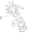
- FIGs. 1 through 13 show a wearable motion assistive device 1 according to a first embodiment of the present invention.
- FIG. 1 shows, as a representative example, an upper-right portion of the wearable motion assistive device 1 corresponding to the right arm portion of a wearer P.
- the wearable motion assistive device 1 includes a body member 2, an upper arm member 3, and a forearm member 4.
- the body member 2 is attached to the body of the wearer P.
- the upper arm member 3 is attached to and extends along the upper arm of the wearer P.
- the forearm member 4 is attached to and extends along the forearm of the wearer P.
- the wearable motion assistive device 1 includes an angle sensor (physical quantity detecting unit) for detecting a physical quantity regarding a movement of a joint, such as the shoulder or elbow joint; a biological sensor (biosignal detecting unit) for detecting a myopotential signal (biosignal) that is generated when the joint at the shoulder, elbow, etc., is moved; and a torque sensor for detecting a driving force transmitted from a motor to the joint.
- an angle sensor physical quantity detecting unit
- biosignal detecting unit for detecting a physical quantity regarding a movement of a joint, such as the shoulder or elbow joint
- biosignal detecting unit for detecting a myopotential signal (biosignal) that is generated when the joint at the shoulder, elbow, etc., is moved
- a torque sensor for detecting a driving force transmitted from a motor to the joint.
- the body member 2 and the upper arm member 3 are mutually rotatably coupled by a shoulder joint mechanism 5.
- the upper arm member 3 and the forearm member 4 are mutually rotatably coupled by an elbow joint mechanism 6.
- the wearable motion assistive device 1 may have a structure similar to the above-described upper-right portion in an upper-left portion thereof.
- the shoulder joint mechanism 5 and the elbow joint mechanism 6 aid the movements of the joint at the shoulder and the elbow, respectively.
- the wearable motion assistive device 1 also includes a control unit 100 having a control circuit for controlling drive units 11 for the shoulder joint mechanism 5 and the elbow joint mechanism 6.
- the control unit 100 controls each drive unit 11 based on the physical quantities and the biosignal detected by the angle sensor, the torque sensor, and the biosignal detecting sensor.
- the control unit 100 controls the drive unit 11 using an autonomous control unit 100A and a voluntary control unit 100B in combination.
- the autonomous control unit 100A when fed with a sensor signal (physical information signal) detected by each sensor, compares the detection value from each sensor with a reference parameter stored in a database to estimate a task and a phase of the wearer.
- the autonomous control unit 100A then generates an autonomous control signal for causing the drive units 11 to generate a driving force corresponding to the estimated phase.
- the voluntary control unit 100B generates a voluntary control signal based on a biopotential signal detected by a biopotential sensor 310.
- a control signal composing unit 100C generates a control signal for the drive units 11 by composing the voluntary control signal from the voluntary control unit 100B and the autonomous control signal from the autonomous control unit 100A.
- the shoulder joint mechanism 5 is described in detail. Because the elbow joint mechanism 6 has substantially the same structure as the shoulder joint mechanism 5, corresponding parts or components with the same functions are designated by similar reference numerals while omitting the detailed description of the elbow joint mechanism 6.
- the shoulder joint mechanism 5 includes first and second connecting members 12 and 13, as well as the drive unit 11. As shown in FIG. 1 , one end of the first connecting member 12 is secured to the body member 2. One end of the second connecting member 13 is secured to the upper arm member 3.
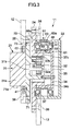
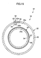
- the drive unit 11 includes a drive portion 21, a gear head 22, and first and second flange members 23 and 24 that are rotatable relative to each other.
- the drive portion 21 has a motor 31 as a drive source.
- the motor 31 includes a motor body 31a and a drive shaft 31b.
- the drive shaft 31b extends into the gear head 22.
- At the end of the drive shaft 31b there is mounted a sun gear 32a that forms a part of a planetary gear mechanism 32.
- the gear head 22 includes two housings: an inner case 34 and an outer case 35.
- the inner case 34 is an example of what the present invention refers to as a rotating body.
- the inner case 34 is also an example of a first component.
- the inner case 34 is formed in the cylindrical shape having one open end.
- the inner case 34 houses the planetary gear mechanism 32 inside.
- the planetary gear mechanism 32 in addition to the aforementioned sun gear 32a, may include plural planetary gears 32b in meshed engagement with the sun gear 32a, and an internal gear 32c (or so-called "ring gear") in meshed engagement with the planetary gears 32b.
- the planetary gear mechanism 32 is just an example of a reduction mechanism; the gear head 22 may adopt other types of reduction mechanism.
- the inner case 23 may house a single gear rather than the plural gears.
- the first flange member 23 is fixed to the motor body 31a so that the first flange member 23 is in thermal connection with the motor 31.
- the planetary gear mechanism 32 includes a support member 36, such as bolts, for supporting the planetary gears 32b.
- the support member 36 may be fixed to the first flange member 23, to which the inner case 34 is fixed.
- the inner case 34 is stationary relative to the motor 31.
- the outer case 35 is formed in the cylindrical shape having one open end.
- the outer case 35 houses the inner case 34. Between the outer case 35 and the inner case 34, there may be disposed plural bearing members 37.
- the second flange member 24 may be formed integrally with the internal gear 32c of the planetary gear mechanism 32.
- the outer case 35 is fixed to the second flange member 24 so that they can rotate together.
- the first connecting member 12 includes a ring-shaped fixing portion 12a and an extension 12b that extends from the fixing portion 12a.
- the end of the extension 12b is attached to the body member 2.
- the fixing portion 12a may be fixed to the first flange member 23 via plural bolts 38.
- the second connecting member 13 includes a ring-shaped fixing portion 13a and an extension 13b extending from the fixing portion 13a.
- the end of the extension 13b is attached to the upper arm member 3.
- the fixing portion 13a may be fixed to the second flange member 24 via plural bolts 38.
- the drive unit 11 of the elbow joint mechanism 6 is configured to rotate the forearm member 4 relative to the upper arm member 3, thereby assisting the motion of the wearer P moving the forearm around the elbow.
- the relative rotation of the inner case 34 to the outer case 35 is achieved by rotating the outer case 35 about the stationary inner case 34.
- the first connecting member 12 may be fixed to the upper arm member 3 and the second connecting member 13 may be fixed to the body member 2. In this case, the inner case 34 rotates within the stationary outer case 35.
- the drive unit 11 includes a circuit board 41 for controlling the motor 31.
- the circuit board 41 is formed in the shape of a ring larger than the outer shape of the motor body 31a.
- the circuit board 41 is mounted on the first flange member 23 in thermal connection therewith.
- the circuit board 41 utilizes the first flange member 23 as a heatsink.
- a packing 42 is provided to cover the circuit board 41 so that the circuit board 41 is not exposed to the outside.
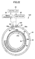
- the circuit board 41 includes a controller 45 that generally controls the drive unit 11, a motor driver 46 for controlling the motor 31, a memory unit 47, and a database 48.
- the drive unit 11 may include a rotation angle detecting unit 51, a temperature detecting unit 52, a distortion/vibration detecting unit 53, and a current information detecting unit 54.
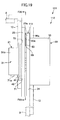
- the rotation angle detecting unit 51 includes a detected member 61, a light-emitting portion 62, a position detecting unit 63, an angle calculating unit 64, a controller 65, and a slit member 66.
- the detected member 61 includes a main body 68 and a fluorescent band 69 provided on the main body 68.
- the main body 68 is a thin band of flexible material.
- the main body 68 may be made of any material, such as resin, rubber, paper, etc., as long as its fluorescence is small.
- the main body 68 is wound around the outer circumferential surface 34a of the inner case 34 along a circumferential direction thereof.
- the main body 68 according to the present embodiment is formed in the shape of a closed loop that is wound around the outer circumferential surface 34a of the inner case 34 once.
- the main body 68 may be formed in the ring shape in advance.
- the main body 68 may be formed in the arc shape adapted to a necessary range of rotation angles to be detected, rather than the closed-loop shape.
- the fluorescent band 69 extends while inclined relative to the longitudinal direction of the main body 68.
- the fluorescent band 69 extends spirally, i.e., inclined with respect to the circumferential direction of the inner case 34.
- the position of the fluorescent band 69 shifts along the axis of the inner case 34 (i.e., laterally in FIG. 5 ).
- the "circumferential direction of the inner case 34" is herein intended to refer to a direction in which the inner case 34 rotates as it executes its relative rotation. Namely, it is a direction along the circumference of the cylindrical inner case 34 in accordance with the present embodiment.
- the fluorescent band 69 extends along the rotating direction of the inner case 34 so that the position of the fluorescent band 69 shifts in a direction perpendicular to the rotation direction of the inner case 34.
- the fluorescent band 69 may comprise a fluorescent tape affixed to the main body 68; or it may be drawn on the main body 68 using fluorescent paint. Alternatively, the fluorescent band 69 may be directly provided on the outer circumferential surface 34a of the inner case 34.
- the "fluorescence" herein is intended to refer to the light emitted by substances in general that emit light upon irradiation with light, thus including the phosphorescence, in which light emission persists after the exciting source is removed.
- the fluorescent band 69 may have a width in a range from 10 ⁇ m to 20 ⁇ m. The width of the fluorescent band 69 is not limited to such range, however.
- the light-emitting portion 62 may be fixed to the outer case 35 as shown in FIG. 6 .
- the light-emitting portion 62 irradiates the detected member 61 with light.
- the light-emitting portion 62 may comprise a point light source including a light-emitting diode (LED).
- the controller 65 controls the timing of light irradiation by the light-emitting portion 62.
- the controller 65 may send a pulsed control signal to the light-emitting portion 62 so that the light-emitting portion 62 can repeatedly turn on and off alternately, thereby irradiating the detected member 61 intermittently.
- the light-emitting portion 62 is turned on and off at the cycle of 1kHz.
- the position detecting unit 63 may include a one-dimensional position detector element.
- One example of the one-dimensional position detector element is a position sensitive detector (PSD).
- PSD position sensitive detector
- the position detecting unit 63 may be attached to the outer case 35 as shown in FIGs. 5 and 6 . Namely, the position detecting unit 63 is stationary relative to the outer case 35.
- the position detecting unit 63 has a light-receiving surface 63a that is disposed opposite the detected member 61.
- the position detecting unit 63 is disposed with a one-dimensional detection line thereof lying along the axis of the inner case 34. When a spot of light is incident on the position detecting unit 63, the position detecting unit 63 can detect the position of entry of the spot light along the axis of the inner case 34. Thus, the position detecting unit 63 can detect the location of the fluorescent band 69 (position information about the fluorescent band 69 in the axial direction of the inner case 34) within an area opposite the light-receiving surface 63a.
- the controller 65 sends a control signal to the position detecting unit 63 that is synchronized with the control signal sent to the light-emitting portion 62.
- the controller 65 controls the position detecting unit 63 so that the position detecting unit 63 performs the position detection process for the fluorescent band 69 when the light-emitting portion 62 is turned off (i.e., when the light-emitting portion 62 is not emitting light).
- the position information about the fluorescent band 69 detected by the position detecting unit 63 is sent to the angle calculating unit 64.
- the angle calculating unit 64 performs a process for calculating a relative rotation angle between the outer case 35 and the inner case 34 from the position information about the fluorescent band 69. The calculation may be based on information regarding the inclined angle of the fluorescent band 69, or the position information about the fluorescent band 69 at a reference position (at the rotation angle 0°).
- the angle calculating unit 64 sends the information about the calculated rotation angle to the controller 45.
- the slit member 66 is disposed between the position detecting unit 63 and the inner case 34.
- the slit member 66 may be fixed to the outer case 35 so that they can move together.
- the slit member 66 has a slit 66a opposite the light-receiving surface 63a of the position detecting unit 63.
- the slit 66a extends along the axis of the inner case 34.
- the controller 65 causes the position detecting unit 63 to stand by when the light-emitting portion 62 is on and perform detection when the light-emitting portion 62 is off.
- the detected member 61 When the light-emitting portion 62 is on, the detected member 61 is irradiated with light so that the fluorescent band 69 is charged with light energy. When the light-emitting portion 62 is off, the fluorescent band 69 emits light. Light emitted by the fluorescent band 69 located along the detection line of the position detecting unit 63 passes through the slit 66a and becomes incident on the position detecting unit 63. Light emitted by the fluorescent band 69 that is located outside the detection line is blocked by the slit member 66 and therefore does not become incident on the position detecting unit 63.
- the position detecting unit 63 detects position information concerning the fluorescent band 69 opposite the position detecting unit 63 based on the incident position of light.
- the angle calculating unit 64 calculates a rotation angle based on the position information about the fluorescent band detected by the position detecting unit 63, and then sends the calculated information to the controller 45.
- the temperature detecting unit 52 includes a temperature sensor 71 for detecting a temperature of the circuit board 41 on which the controller 45 is mounted, and a motor temperature calculating unit 72.
- the temperature sensor 71 is in contact with the circuit board 41, as shown in FIG. 3 .
- the temperature sensor 71 can directly detect the temperature of the circuit board 41.
- the temperature sensor 71 sends information about the detected temperature to the controller 45 and also to the motor temperature calculating unit 72.
- the motor temperature calculating unit 72 calculates a temperature of the motor 31 by solving a one-dimensional heat equation.
- the motor temperature calculating unit 72 sends information about the calculated temperature of the motor 31 to the controller 45.
- the detection of the temperature of the circuit board 41 and that of the motor 31 are performed continuously during the operation of the drive unit 11.
- the temperature detecting unit 52 may comprise a separate temperature sensor 71a for directly detecting the temperature of the motor 31, as indicated by two-dot chain lines in FIG. 3 , instead of the motor temperature calculating unit 72.
- the distortion/vibration detecting unit 53 includes a distortion/vibration sensor 73.
- the distortion/vibration sensor 73 is attached to the first flange member 23, as shown in FIG. 3 .
- the distortion/vibration sensor 73 detects an amount of distortion in the first flange member 23 and also a state of vibration (such as the presence or absence of chattering vibration) of the first flange member 23. The detection of the distortion amount and the vibration state is performed continuously during the operation of the drive unit 11.
- the current information detecting unit 54 includes a current detecting unit 75 and a calculating unit 76.
- the current detecting unit 75 may detect a value of electric current that flows in the motor 31 by measuring an electric current flowing in the motor driver 46.
- the current detecting unit 75 sends information about the detected current value to the calculating unit 76.
- the calculating unit 76 integrates the value of electric current flow in the motor 31 since the initial startup of the drive unit 11 with respect to time, to calculate how much current has flowed through the motor 31 since the initial startup time of the drive unit 11 up to the present time.
- the calculating unit 76 sends a time-integrated current value (total operation time) to the controller 45.
- the database 48 there is stored data concerning an allowable temperature of the circuit board 41 for preventing malfunction; an allowable temperature of the motor 31 for preventing malfunction; an allowable distortion amount of the first flange member 23; and the life of the motor 31, for example.
- the controller 45 includes a motor monitoring unit 45A for monitoring an operational status of the motor 31, and a motor controller 45B for limiting a drive signal to the motor 31 based on a result of monitoring by the motor monitoring unit 45A in order to prevent an overload state of the motor 31.
- the motor monitoring unit 45A includes a determination unit 45C for determining whether the total integrated value of the current supplied to the motor 31 exceeds a preset threshold, and a remaining life calculating unit 77. When the determination unit 45C determines that the total integrated value of current exceeds the preset threshold, the motor controller 45B controls the motor 31 so that the drive signal supplied to the motor 31 is gradually decreased at a predetermined rate (such as decreasing at the rate of 5% to 10% of the maximum output per second).
- the controller 45 compares information about the temperatures of the circuit board 41 and the motor 31 received from the temperature detecting unit 52 with the acceptable values stored in the database 48 and the total operation time of the motor 31 with an average life of the motor 31. When it is likely that either the temperature of the circuit board 41 or that of the motor 31 will exceed the acceptable values, the controller 45 reduces or terminates the driving of the motor 31 by, e.g., switching to a slower speed.
- the controller 45 compares the distortion amount or the state of vibration sent from the distortion/vibration detecting unit 53 with the acceptable values stored in the database, and reduces or terminates the driving of the motor 31 as needed.
- the drive unit 11 can prevent the forcible driving of the motor 31 when the performance of the motor 31 is lowered, or the overheating of the motor 31.
- the drive signal is gradually decreased so that the driving force of the motor 31 can be reduced, thereby extending the life of the motor 31.
- Such extension of life of the motor 31 particularly contributes to the lessening of burden on the wearer when the drive unit 11 is embedded within the wearer's body (see FIGs. 23 and 24 ) where the motor 31 cannot be easily replaced.
- the drive signal supplied to the motor 31 is gradually decreased at the predetermined rate (such as at the rate of 5% to 10% of the maximum output per second).
- the predetermined rate such as at the rate of 5% to 10% of the maximum output per second.
- the controller 45 includes the remaining life calculating unit 77.
- the remaining life calculating unit 77 receives from the current information detecting unit 54 information about the time-integrated value of the electric current that has flowed through the motor 31.
- the database 48 there is stored information about the time-integrated current values associated with the end of life of the motor as determined by experiment or actual use (such as a preset reference value for determining a lifetime).
- the remaining life calculating unit 77 compares the time-integrated current value received from the current information detecting unit 54 with the information stored in the database, in order to calculate a remaining life of the motor 31.
- the controller 45 determines that it is the replacement time when the time-integrated value of the electric current flow through the motor 31 exceeds a predetermined reference value. The detection of remaining life is performed continuously during the operation of the drive unit 11.
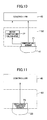
- the drive unit 11 includes a communication unit 78.
- the memory unit 47 receives various information about the values detected or calculated by the temperature detecting unit 52, the distortion/vibration detecting unit 53, the current information detecting unit 54, and the controller 45.
- the memory unit 47 also stores history information about the above information.
- the communication unit 78 may comprise a radio communication unit.
- the communication unit 78 may transmit the various information detected or calculated by the temperature detecting unit 52, the distortion/vibration detecting unit 53, the current detecting unit 75, and the controller 45 to the outside periodically.
- FIG. 12B shows a graph plotting the drive current in the motor 31 versus time. As shown in FIG. 12B , the drive current in the motor 31 changes over time depending on the angle and torque when the shoulder or elbow joint is driven.
- a first acceptable value I A and a second acceptable value I B of the drive current are set in the database 48 in advance (I A ⁇ I B ).
- the drive unit 11 includes the database (storage unit) 48, in which the first acceptable value I A and the second acceptable value I B higher than the first acceptable value I A of the current value supplied to the motor 31 are stored.
- the remaining life calculating unit 77 calculates a remaining life by integrating an excess current value above the first acceptable value I A and subtracting the total use time up to the present time from an average life.
- the motor controller 45B controls the motor 31 so that the electric current supplied to the motor 31 gradually decreases at a predetermined rate (such as at the rate of 5% to 10% of the first acceptable value I A per second).
- the motor controller 45B when the drive current exceeds the second acceptable value I B , controls the motor 31 so that the electric current supplied to the motor 31 gradually decreases at a predetermined rate.
- the rate at which the current value is decreased may be set as follows. For example, the current value in excess of the second acceptable value I B is reduced to the second acceptable value I B instantaneously (such as within one second), or to the first acceptable value within several seconds.
- the drive current may be reduced smoothly by using a sigmoid function, a Bézier curve, or a spline curve.
- the control unit 100 automatically sets an assist ratio (the ratio of torque produced by the drive unit to torque produced by the wearer) lower.
- the aforementioned predetermined rate may be set to any desired value depending on the particular situation. For example, the drive current is reduced at the rate in a range from 0.1% to 1% of the maximum output per second before the motor 31 is stopped.
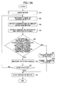
- the controller 45 In response to a drive instruction from the control unit 100 to the drive unit 11, the controller 45 starts to drive the motor 31 in a first step S1.
- the current information detecting unit 54 detects a value of electric current that flows in the motor 31 and calculates a time-integrated value of the current value (monitoring unit).
- the temperature detecting unit 52 detects a temperature of the circuit board 41 and calculates a temperature of the motor 31 (monitoring unit).
- the distortion/vibration detecting unit 53 detects an amount of distortion and a vibration state in the first flange member 23 (monitoring unit).
- the second to the fourth steps S2, S3, and S4 are performed simultaneously. Alternatively, these steps may be performed sequentially in any order.
- a fifth step S5 the controller 45 compares the various information detected in the second through the fourth steps S2, S3, and S4 with the acceptable values or reference values stored in the database 48, and determines whether the operating status of the drive unit 11 is normal (determination unit). For example, the controller 45 determines whether the time-integrated value of the current flow through the motor 31 is below the predetermined amount; whether the temperature of the circuit board 41 is below the acceptable value; whether the temperature of the motor 31 is below the acceptable value; whether the distortion amount of the first flange member 23 is below the acceptable value; and whether there is any sign of chattering vibration based on the vibration state.
- the rotation angle detecting unit 51 in a sixth step S6 detects a relative rotation angle of the first and the second flange members 23 and 24.
- the controller 45 determines whether a stop position is reached based on the detected rotation angle. When the controller 45 determines that the stop position is not yet reached, the process is repeated from the second step S2 sequentially. When the controller 45 determines that the stop position is reached, the motor 31 is stopped in an eighth step S8, thereby completing the process.
- the routine of the process branches to a ninth step S9.
- the driving of the motor 31 is reduced by, e.g., entering into a low-speed operation (motor control unit).
- a deceleration control is performed whereby the driving of the motor 31 is switched to a low-speed rotation at a predetermined rate, for example, in S9, thereby reducing the driving of the motor 31.
- a tenth step S10 information detected by the various detecting units is transmitted to the outside by the communication unit 78.
- the driving of the motor 31 is stopped at about the same time as the step S10.
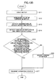
- the maintenance control process is performed in parallel with the above-described main control process ( FIG. 13A ), as an interrupt process at preset time intervals (such as at one-minute or 10-minutes intervals).
- the first through sixth steps S11 to S16 are the same as the first through the fifth steps S1 to S5 and the ninth step S9 of FIG. 13A described above and are therefore not described.
- step S17 the controller 45 transmits the operating status of the motor 31 (such as whether the time-integrated value of current flow through the motor 31 is below the predetermined amount; whether the temperature of the circuit board 41 is below the acceptable value; whether the temperature of the motor 31 is below the acceptable value; whether the distortion amount of the first flange member 23 is below the acceptable value; and whether there is a sign of chattering vibration based on the vibration state) to an information management apparatus 84 at a center (see FIG. 7 ) via the communication network 83.
- the operating status of the individual wearable motion assistive device 1 can be analyzed in the information management apparatus 84 based on a database 88 at the center.
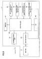
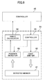
- the maintenance management system 81 includes the wearable motion assistive device 1 and the radio terminal 82 provided on the part of each user, and the information management apparatus 84 provided on the part of the supplier and connected to the user-side radio terminal 82 via the communication network 83, such as the Internet.
- the information management apparatus 84 at the center is configured to manage the operational status of the wearable motion assistive device 1.
- the information management apparatus 84 includes a communication unit 85 connected to the communication network 83; a storage unit 86 including the database 88 for successively storing information (including the history information about the motor 31) about the operational status of the individual wearable motion assistive device 1 that is inputted via the communication unit 85; and an analyzing unit 87 for analyzing the wearable motion assistive device 1 based on the information about the individual operational status stored in the storage unit 86.
- the analyzing unit 87 analyzes the history information stored in the database 88 to generate analysis information which may concern the life of the drive unit 11 or the presence or absence of an overload state in the drive unit 11. When serious analyzed result is obtained, the analyzing unit 87 transmits the related analysis information to the relevant wearable motion assistive device 1.
- the communication unit 85 includes a receiver unit 85A and a transmitter unit 85B.
- the receiver unit 85A receives history information about the drive status of the motor 31 that is transmitted from the drive unit 11 via the communication unit 78 and the communication network 83.
- the transmitter unit 85B when it is determined that maintenance of the motor 3 is required based on the analysis result obtained by the analyzing unit, transmits maintenance information to the relevant drive unit 11.
- the wearable motion assistive device 1 thus includes the communication unit 78 for the individual drive unit 11 as described above.
- the wearable motion assistive device 1 includes plural communication units 78, such as the communication unit 78 provided for the drive unit 11 of the shoulder joint mechanism 5, and the communication unit 78 provided for the drive unit 11 for the elbow joint mechanism 6.
- These plural communication units 78 send information about the operating status of each drive unit 11 onto the communication network 83 periodically, for example, via the radio terminals 82.
- another wearable motion assistive device 1 being used by another user also sends information about the individual drive units 11 onto the communication network 83.
- the information management apparatus 84 provided on the supplier end receives the information from each user via the communication network 83, and centrally manages the information on the database 88.
- the history information about the drive status of the motor 31 transmitted from the drive unit 11 via the communication unit and the communication network 83 is stored in the database 88 at the center for managing the operational status of the motion assistive device.
- the history information stored in the database 88 is analyzed to obtain an analysis result based on the information about the life of the drive unit 11 or the presence or absence of an overload state. Based on such analysis result, maintenance information is transmitted to the relevant drive unit 11. In this way, whether the drive unit 11 is normal can be constantly analyzed, so that the wearer can be immediately notified via a radio alert signal in the event of some form of abnormality in the drive unit 11.
- the influence of the scattering of light in the rotation angle detecting unit 51 can be curbed, so that an improved rotation angle detection accuracy can be achieved.
- the fluorescent band 69 emits light by itself, there is no problem of the scattering of light at the edge of the fluorescent band 69, whereby the light without scattering becomes incident on the position detecting unit 63.
- the use of the fluorescent band 69 prevents an error due to the scattering of light, thereby improving the rotation angle detection accuracy.
- the light-emitting portion 62 emits light intermittently and the position detecting unit 63 receives the light emitted by the fluorescent band 69 when the light-emitting portion 62 is turned off.
- the light emitted by the fluorescent band 69 can be reliably detected without interference from the light emitted by the light-emitting portion 62.
- the detected member 61 comprises the main body 68 with the fluorescent band 69 attached thereon.
- This structure enables more accurate setting of the inclination angle of the fluorescent band 69 relative to the circumferential direction than when the fluorescent band 69 is directly attached to a rotating body.
- the mounting of the fluorescent band 69 is also simplified.
- the detected member 61 is attached to the outer circumferential surface 34a of the inner case 34, which is a gear case. This eliminates the need for an angle detecting portion on the rotating axle, thereby reducing the size of the drive unit 11.
- a detection error may be caused by a misalignment or distortion between the potentiometer shaft and the rotating shaft.
- the rotation angle detecting unit 51 is directly built inside the gear/motor system, detection error does not easily occur and a highly reliable detection can be realized.
- the slit member 66 is not necessarily required and may be omitted.
- the slit member 66 when provided, blocks excess light from the front or rear of the detection line, thereby improving the rotation angle detection accuracy.
- the operating status of the motor is monitored by a sensor, and an alert is issued if data concerning the operating status exceeds a threshold.
- a supplier of the drive unit needs to respond to individual drive units every time an alert is issued.
- a drive unit in which an operating status of the motor 31 is monitored, and an active corrective operation is performed to achieve an appropriate operating status.
- the temperature of the first flange member 23 increases when the motor 31 is driven. If a circuit board, which also generates heat, is mounted on such flange member, the temperature of the circuit board may become excessively high. For this reason, circuit boards are generally located away from motors.
- the circuit board 41 is mounted on the first flange member 23.
- the drive unit 11 includes the temperature detecting unit 52 for detecting the temperature of the circuit board 41.
- the temperature of the circuit board 41 is constantly monitored by the temperature detecting unit 52. When it is likely that the temperature will exceed an acceptable value, the amount of heat transferred from the motor 31 to the first flange member 23 is reduced by, for example, reducing the driving of the motor 31. In this way, the first flange member 23 can function properly as a heatsink for the circuit board 41, thereby controlling the temperature increase in the circuit board 41.
- the circuit board 41 can be mounted on the first flange member 23, which is thermally connected to the motor 31. Because the circuit board 41 can be located adjacent the motor 31, the size of the drive unit 11 can be reduced.
- the temperature detecting unit 52 monitors the temperature of the motor 31 and when the temperature of either the motor 31 or the circuit board 41 is likely to exceed the acceptable value, the driving of the motor 31 is reduced.
- the first flange member 23 functioning as a heatsink for the motor 31 or the circuit board 41, excess temperature increase can be prevented.
- the size of the drive unit 11 can be reduced and improved reliability can be obtained.
- the motor 31 used in the wearable motion assistive device 1 is not so much rotated a great number of times during its life as it is typically used in an overload state for supporting a heavy load, for example. As a method of detecting the remaining life of the motor 31, the total number of revolutions of the motor could be counted. However, this is not suitable for the motor 31 for the wearable motion assistive device 1.
- the controller 45 determines the life of the motor 31 by time-integrating the value of electric current that flows in the motor 31 from the time of initial operation.
- the overload state of the motor 31 is largely dependent on the magnitude of the electric current that flows through the motor 31.
- the degree of overloading of the motor 31 can be roughly determined. In this way, the drive unit 11 can appropriately determine the life of the motor 31 in an overload state.
- the memory unit 47 in the drive unit 11 stores various detected information or the like, providing information about the kind of environment that the drive unit 11 has been used in up to the present time. Such information enables improvement in maintenance efficiency, for example.
- the communication unit 78 in the drive unit 11 transmits the various detected information to the outside, enabling the monitoring of the operating status and the determination of the remaining life of the individual drive unit 11 externally.
- the communication unit 78 in the drive unit 11 transmits the various detected information to the outside, enabling the monitoring of the operating status and the determination of the remaining life of the individual drive unit 11 externally.
- the supplier end it becomes possible for the supplier end to indicate a suggested replacement time, or to prepare replacement parts for the drive unit 11 that is about to reach its replacement time.
- each of the plural drive units 11 is constructed as an independent unit having the various detecting units 52, 53, and 54, the circuit board 41 including the controller 45, and the communication unit 78, the individual drive units 11 need to be only connected via power supply cables, thus making the wearable motion assistive device 1 more convenient to use.
- the fluorescent band 69 is installed on the inner case 34 and the position detecting unit 63 is mounted on the outer case 35.
- the fluorescent band 69 may be installed on the outer case 35 and the position detecting unit 63 may be mounted on the inner case 34.
- the position detecting unit 63 may not be configured to detect light when the light-emitting portion 62 is turned off.
- the frequency of the light emitted by the fluorescent band 69 may be made different from that of the light emitted by the light-emitting portion 62, and the position detecting unit 63 may be configured to respond to the frequency of the fluorescent band 69.
- the position detecting unit 63 can perform the position detection process based on the light emitted by the fluorescent band 69 even when the light-emitting portion 62 is turned on.
- the selection or adjustment of the position detecting unit 63 is easier and detection error is less likely to develop by performing the detection process when the light-emitting portion 62 is turned off.
- a wearable motion assistive device 91 according to a second embodiment of the present invention is described with reference to FIGs. 14 to 16 .
- Parts or elements having the same functions as those of the wearable motion assistive device 1 of the first embodiment are designated with similar reference numerals and their description is omitted.
- the wearable motion assistive device 91 includes a shoulder joint mechanism 5 and an elbow joint mechanism 6, each having a drive unit 92.
- the drive unit 92 is similar to the drive unit of the first embodiment, with the exception of a rotation angle detecting unit 93 which differs from the rotation angle detecting unit 51 of the first embodiment.
- the drive unit 92 includes a controller 45, a motor driver 46, a memory unit 47, a database 48, a temperature detecting unit 52, a distortion/vibration detecting unit 53, and a current information detecting unit 54.
- the rotation angle detecting unit 93 includes a detected member 94, a first light-emitting portion 95, a second light-emitting portion 96, a position detecting unit 63, an angle calculating unit 64, a controller 65, and a slit member 66.
- the detected member 94 includes a main body 68 and a reflecting band 97 installed on the main body 68.
- the main body 68 is painted black to reduce light reflectivity.
- the reflecting band 97 extends while inclined in the longitudinal direction of the main body 68. As shown in FIG. 14 , when the main body 68 is wound around the inner case 34, the reflecting band 97 extends spirally in the circumferential direction of the inner case 34. Thus, when the inner case 34 is relatively rotated, the position of the reflecting band 97 changes in the axial direction of the inner case 34.
- the reflecting band 97 is formed of a material with high light reflectivity.
- the reflecting band 97 may be provided by a light reflective tape affixed to the main body 68, or may be drawn with a light reflective paint. Alternatively, the reflecting band 97 may be directly provided on the outer circumferential surface of the inner case 34.
- the reflecting band 97 has a width in a range from 10 ⁇ m to 20 ⁇ m. The width of the reflecting band 97 however is not limited to such range.
- the first and the second light-emitting portions 95 and 96 may be fixed to the outer case 35, as shown in FIG. 14 .
- the first and second light-emitting portions 95 and 96 are spaced apart from each other in the axis direction of the inner case 34.
- the first and second light-emitting portions 95 and 96 may be spaced apart from the center of the detected member 94 by the same distance in the opposite directions, along the axis of the inner case 34.
- the first and second light-emitting portions 95 and 96 are configured to irradiate the detected member 94 with light.
- the controller 65 controls the timing of irradiation of the first and second light-emitting portions 95 and 96.
- the controller 65 may be configured to send a pulsed control signal to the first and second light-emitting portions 95 and 96 so that the first and second light-emitting portions 95 and 96 are turned on alternately.
- the first and second light-emitting portions 95 and 96 may be turned on and off at the period of 1kHz; however, the first and second light-emitting portions may be turned on and off at other periods.
- the position detecting unit 63 receives the light from the first light-emitting portion 95 that is reflected by the reflecting band 97 when the first light-emitting portion 95 is turned on.
- the position detecting unit 63 receives the light emitted by the second light-emitting portion 96 that is reflected by the reflecting band 97 when the second light-emitting portion 96 is turned on. Based on a distribution of the reflected light that is detected when the first light-emitting portion 95 is turned on, and a distribution of the reflected light detected when the second light-emitting portion 96 is turned on, the position detecting unit 63 detects position information about the reflecting band 97 in the axial direction of the inner case 34.
- the position detecting unit 63 detects the position of a peak ("first peak”) of the distribution of the reflected light detected when the first light-emitting portion 95 is turned on, and the position of a peak ("second peak") of the distribution of the reflected light detected when the second light-emitting portion 96 is turned on. The position detecting unit 63 then determines an intermediate position between the first peak and the second peak as an instantaneous position of the reflecting band 97.
- first peak the position of a peak
- second peak the position of a peak
- the position detecting unit 63 detects the first and second peaks at a reference position (such as at the rotation angle 0°) and a predetermined position (such as the rotation angle 180°). The position detecting unit 63 then determines the intermediate position at each position as reference position information and predetermined position information about the reflecting band 97, respectively. Such information is then stored in the angle calculating unit 64.
- the angle calculating unit 64 receives the position information about the reflecting band 97 detected by the position detecting unit 63 at an arbitrary angle. Based on the reference position information and the predetermined position information and the like about the reflecting band 97, the angle calculating unit 64 calculates a relative rotation angle between the outer case 35 and the inner case 34.
- the position information about the reflecting band 97 may be detected in other ways than by determining the intermediate position at the first and second peaks. Any method capable of identifying a position corresponding to a rotation angle from the reflected light distribution due to the first light-emitting portion 95 and the reflected light distribution due to the second light-emitting portion 96 can be suitably adopted.
- the influence of the scattering of light in the rotation angle detecting unit 93 can be curbed, so that improved rotation angle detection accuracy can be achieved.
- the reflected light distribution due to the first light-emitting portion 95 and the reflected light distribution due to the second light-emitting portion 96 are different. This is because the diffuse reflection caused at the edge of the reflecting band 97 when the first light-emitting portion 95 is turned on differs from the diffuse reflection caused at the edge of the reflecting band 97 when the second light-emitting portion 96 is turned on, resulting in different scattering characteristics.
- the drive unit 11 by detecting the position information about the reflecting band 97 based on the two reflected light distributions having different scattering characteristics, the probability of the detection result being influenced by the scattering in the individual light distribution can be reduced. In this way, the influence of the scattering of light at the edge of the reflecting band 97 can be curbed, whereby improved rotation angle detection accuracy can be achieved.
- the edges of the reflecting band 97 on either side lie side by side along the axis of the inner case 34.
- the reflected light distribution due to the first light-emitting portion 95 and the reflected light distribution due to the second light-emitting portion 96 tend to differ from each other.
- the influence of the scattering of light at the edges can be further curbed, so that improved rotation angle detection accuracy can be obtained.
- the first and second light-emitting portions 95 and 96 are spaced apart from the detected member 94 by the same distance in the opposite directions along the axis of the inner case 34, development of error becomes less likely so that improved detection accuracy can be achieved.
- the mutually different two light distributions can be reliably obtained. Namely, by receiving the reflected light from the first light-emitting portion 95 with the position detecting unit 63 when the second light-emitting portion 96 is turned off, the reflected light from the first light-emitting portion 95 is not contaminated by the reflected light from the second light-emitting portion 96.
- the first and second light-emitting portions 95 and 96 may not necessarily emit light alternately.
- the first light-emitting portion 95 and the second light-emitting portion 96 may be configured to emit light with different frequencies.
- the position information about the reflecting band 97 can be detected from the two reflected light distributions caused by the first and second light-emitting portions 95 and 96 as they emit light simultaneously.
- the outer case 35 may be fitted with the reflecting band 97 and the inner case 34 may be fitted with the position detecting unit 63.
- a wearable motion assistive device 101 according to a third embodiment of the present invention is described with reference to FIGs. 17 and 18 .
- Parts or elements with the same functions as those of the wearable motion assistive device 1 according to the first embodiment are designated with similar reference numerals and their description is omitted.
- the wearable motion assistive device 101 includes a shoulder joint mechanism 5 and an elbow joint mechanism 6, each having a drive unit 102.
- the drive unit 102 is similar to the drive unit of the first embodiment with the exception of the rotation angle detecting unit 103 which differs from the rotation angle detecting unit 51 of the first embodiment.
- the rotation angle detecting unit 103 includes a fluorescent band 69, a light-emitting portion 62, a position detecting unit 63, an angle calculating unit 64, a controller 65, and a slit member 66.
- the first flange member 23 is an example of what the present invention refers to as the first component; the second flange member 24 is an example of the second component.
- the fluorescent band 69 is provided on an end face 23a of the first flange member 23.
- the fluorescent band 69 is disposed opposite the second flange member 24 and extends spirally. Namely, the fluorescent band 69 extends in the direction of rotation of the second flange member 24 such that the position of the fluorescent band 69 changes in a direction perpendicular to the direction of rotation of the second flange member 24 (which is the radial direction of the first flange member 23 in the present embodiment).
- the light-emitting portion 62 may be fixed to the second flange member 24.
- the light-emitting portion 62 is turned on and off alternately so that the fluorescent band 69 is irradiated with light intermittently.
- the position detecting unit 63 may be attached to the second flange member 24 as shown in FIG. 17 , opposite the fluorescent band 69.
- the position detecting unit 63 has a one-dimensional detection line lying in the radial direction of the first flange member 23.
- the position detecting unit 63 has a light-receiving surface 63a.
- the position detecting unit 63 detects a location of the fluorescent band 69 (i.e., position information about the fluorescent band 69 in the radial direction of the first flange member 23) in an area opposite the light-receiving surface 63a.
- the angle calculating unit 64 calculates a relative rotation angle between the first and second flange members 23 and 24 from the detected position information about the fluorescent band 69.
- the slit member 66 is provided between the position detecting unit 63 and the first flange member 23.
- the slit member 66 which is stationary relative to the position detecting unit 63, includes a slit 66a lying in a radius direction of the first flange member 23.
- the slit member 66 is not necessarily required.
- the influence of the scattering of light in the rotation angle detecting unit 103 can be curbed, whereby rotation angle detection accuracy can be improved.
- the fluorescent band 69 emits light by itself, the problem of diffuse reflection of light at the edge of the fluorescent band 69 is not caused, so that light with controlled scattering becomes incident on the position detecting unit 63.
- the fluorescent band 69 prevents the error due to the scattering of light, thereby improving the rotation angle detection accuracy.
- the fluorescent band 69 may be provided on the second flange member 24 and the position detecting unit 63 may be provided on the first flange member 23.
- a wearable motion assistive device 111 according to a fourth embodiment of the present invention is described with reference to FIGs. 19 and 20 .
- Parts or elements with the same functions as those of the wearable motion assistive device 1, 91, or 101 according to the first, second, or third embodiment are designated with similar reference numerals, and their description is omitted.
- the wearable motion assistive device 111 includes a shoulder joint mechanism 5 and an elbow joint mechanism 6, each having a drive unit 112.
- the drive unit 112 is similar to the drive unit of the first embodiment with the exception of a rotation angle detecting unit 113 that differs in structure from the rotation angle detecting unit 51 according to the first embodiment.
- the rotation angle detecting unit 113 includes a reflecting band 97, a first light-emitting portion 95, a second light-emitting portion 96, a position detecting unit 63, an angle calculating unit 64, a controller 65, and a slit member 66.
- the reflecting band 97 is installed on an end face 23a of the first flange member 23, opposite the second flange member 24 and extending spirally. Namely, the reflecting band 97 extends such that its position changes in a direction perpendicular to the direction of rotation of the second flange member 24 (i.e., in a radius direction of the first flange member 23 in the present embodiment) as the second flange member 24 is rotated (in a circumferential direction).
- the first and second light-emitting portions 95 and 96 may be fixed to the second flange member 24.
- the first and second light-emitting portions 95 and 96 are spaced apart from each other in the radius direction of the second flange member 24.
- the first and second light-emitting portions 95 and 96 may be turned on alternately.
- the position detecting unit 63 may be attached to the second flange member 24 opposite the reflecting band 97, as shown in FIG. 20 .
- the position detecting unit 63 has a one-dimensional detection line lying in a radius direction of the first flange member 23. For example, the position detecting unit 63 detects the position of a peak ("first peak") in a reflected light distribution detected when the first light-emitting portion 95 is turned on, and the position of a peak ("second peak") of a reflected light distribution detected when the second light-emitting portion 96 is turned on, as in the second embodiment.
- the position detecting unit 63 may then determine an intermediate position between the first and second peaks as the instantaneous position information about the reflecting band 97.
- the position detecting unit 63 may employ other detection method.
- the angle calculating unit 64 calculates a relative rotation angle between the first flange member 23 and the second flange member 24 from the detected position information about the reflecting band 97.
- the slit member 66 is disposed between the position detecting unit 63 and the first flange member 23.
- the slit member 66 which includes a slit 66a lying along a radius direction of the first flange member 23, is stationary relative to the position detecting unit 63.
- the slit member 66 is not necessarily required.
- the influence of the scattering of light in the rotation angle detecting unit 113 is curbed, whereby improved rotation angle detection accuracy can be obtained.
- position information about the reflecting band 97 is detected based on the two reflected light distributions having different scattering characteristics. In this way, the influence of scattering in the individual light distribution on a detection result can be reduced, whereby improved rotation angle detection accuracy can be obtained.
- the reflecting band 97 may be provided on the second flange member 24 while the position detecting unit 63 may be installed on the first flange member 23.
- a wearable motion assistive device 121 according to a fifth embodiment of the present invention is described with reference to FIGs. 21 and 22 .
- Parts or elements having the identical or corresponding functions to those of the wearable motion assistive device 1 according to the first embodiment are designated by similar reference numerals, and their description is omitted.
- the wearable motion assistive device 121 includes a shoulder joint mechanism 5 and an elbow joint mechanism 6, each having a drive unit 122.
- the drive unit 122 is similar to the drive unit of the first embodiment with the exception of a rotation angle detecting unit 123 that differs in structure from the rotation angle detecting unit 51 of the first embodiment.
- the rotation angle detecting unit 123 includes a detected member 61 with a fluorescent band 69, a light-emitting portion 62, a position detecting unit 63, an angle calculating unit 64, a controller 65, and a slit member 66.
- the inner case 34 is an example of what the present invention refers to as the first component; the outer case 35 is an example of the second component.
- the detected member 61 includes a main body 68 whose thickness gradually increases in a circumferential direction of the inner case 34.
- the fluorescent band 69 is provided on the surface of the main body 68. Specifically, the fluorescent band 69 extends along a direction of rotation of the inner case 34 (i.e., circumferential direction) such that the position of the fluorescent band 69 changes in a direction (which is in a radius direction of the inner case 34 in the present embodiment) perpendicular to the direction of rotation of the inner case 34 as the inner case 34 is rotated.
- the position of the fluorescent band 69 changes in the radius direction of the inner case 34.
- the light-emitting portion 62 may be fixed to the second flange member 24.
- the light-emitting portion 62 is turned on and off alternately so that the fluorescent band 69 is irradiated with light intermittently.
- the position detecting unit 63 may be attached to the outer case 35 as shown in FIG. 17 , opposite the fluorescent band 69.
- the position detecting unit 63 is configured to detect the amount of light that is incident on the light-receiving surface 63a. Based on the amount of light incident on the light-receiving surface 63a, the position detecting unit 63 detects the location of the fluorescent band 69 (i.e., position information about the fluorescent band 69 in the radius direction of the inner case 34) within an area opposite the light-receiving surface 63a.
- the angle calculating unit 64 calculates a relative rotation angle between the outer case 35 and the inner case 34 from the detected position information about the fluorescent band 69.
- the influence of the scattering of light in the rotation angle detecting unit 123 can be curbed, so that improved rotation angle detection accuracy can be obtained.
- the fluorescent band 69 emits light by itself, the problem of diffuse reflection in areas in front and the rear of the fluorescent band 69 does not occur, whereby improved rotation angle detection accuracy can be obtained.
- the detected member 61 may be provided on the outer case 35 while the position detecting unit 63 may be provided on the inner case 34.
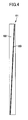
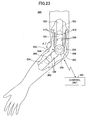
- FIG. 23 shows a side view of the embedded motion assistive device 200 according to the sixth embodiment.
- the embedded motion assistive device 200 which is configured to aid the movement of a joint 220 of a wearer, includes a movement aiding unit 230 attached to the joint 220, and a control unit 100.
- the control unit 100 includes a control circuit for controlling the movement aiding unit 230 externally by radio.
- the movement aiding unit 230 includes a first limb 250 coupled to a first bone 222 that is the upper arm bone of the elbow joint 220; a second limb 260 coupled to a second bone 224 that includes the radius on the thumb side and the ulna on the little finger side below the elbow joint 220; and a drive unit 290 disposed between the first limb 250 and the second limb 260 and configured to drive the second limb 260 relative to the first limb 250 in a direction of rotation of the joint. From the upper end of the first limb 250 protrudes a coupling portion 252 connected to the first bone 222. From the lower end of the second limb 260 protrudes a coupling portion 262 connected to the second bone 224.
- the coupling portions 252 and 262 of the first limb 250 and the second limb 60 may be made of a corrosion-resistant material, such as titanium, a titanium alloy, or ceramics as these coupling portions 252 and 262 are directly attached to the bones.
- the coupling portions 252 and 262 may be connected to the bones by using a fastening member, such as screws or rivets, made of a corrosion resistant material such as titanium, a titanium alloy, or ceramics.
- a radio transceiver On a side surface of the drive unit 290, there are provided a radio transceiver and a control unit.
- the radio transceiver is configured to transmit a drive information signal to the outside of the body and to receive a control signal from the outside.
- the control unit is configured to supply a drive current to the drive unit 290.
- the drive unit 290 also includes a motor 292 which may be a DC motor, an AC motor, or an ultrasonic motor.
- the motor 292 is made up of a stator and a rotor, either one consisting of a coil while the other consisting of a permanent magnet.
- a driving force generated by a relative rotation between the stator and the rotor of the motor 292 is transmitted to the second limb 260 via a reduction mechanism, such as one comprising reduction gears.
- the controller 45 of the drive unit 290 generates a drive current that is supplied to the coil of the motor 292, whereby the second limb 260 is rotated relative to the first limb 250.
- a biopotential sensor 310 for detecting a biopotential in the upper arm.
- a biopotential signal is produced that may include a neurotransmission signal or a myopotential signal. Because the biopotential sensor 310 is embedded in the muscles of the upper arm, the biopotential signal can be detected directly without the intermediary of the skin. Thus, the biopotential signal can be detected more accurately than when the sensor is affixed to the upper surface of the skin of the upper arm.
- a rechargeable battery unit 320 is housed within each of the first limb 250 and the second limb 260.
- the rechargeable battery unit 320 includes a rechargeable battery 324 and a charger unit 322 for charging the rechargeable battery 324 from the outside via electromagnetic induction.
- a pair of such rechargeable battery units 320 is provided in each limb, one being a main power supply and the other being a standby power supply.
- the rechargeable battery units 320 can be charged while attached inside the body, they can be used for a long time until their chargeable life ends (i.e., within their possible number of times of recharges) while attached to the wearer.
- the rechargeable battery unit 320 may be provided for each of the first limb 250 and the second limb 260. Alternatively, the rechargeable battery unit 320 may be provided inside either one of the limbs 250 and 260.
- the drive unit 290 also includes a torque sensor (physical quantity sensor) 294 for detecting a torque T generated with the supplied drive current, and an angle sensor (physical quantity sensor) 296 for detecting a rotation angle ⁇ between the first limb 250 and the second limb 260.
- the torque sensor 294 and the angle sensor 296 output torque and angle detection signals to the drive unit 290.
- the torque sensor 294 may comprise a magnetorestrictive torque sensor configured to detect a distortion in a shaft transmitting a rotary driving force, or an electromagnetic torque sensor configured to detect a phase difference between a drive-side gear and a load-side gear of the motor 292 electromagnetically.
- the angle sensor 296 may comprise a rotary encoder configured to output a number of pulses corresponding to a rotation angle, or a potentiometer whose resistance value varies depending on the rotation angle.
- stress sensors (physical quantity sensors) 330 for detecting a stress (strain) that is caused when the motor is driven.
- the stress sensor 330 may comprise a strain gauge configured to output a detection signal corresponding to the stress applied to the first limb 250 or the second limb 260 to the controller 45 of the drive unit 290.
- the controller 45 transmits the individual detection signals received from the torque sensor 294, the angle sensor 296, the biopotential sensor 310, and the stress sensor 330 to the control unit 100 via the radio transceiver.
- the control unit 100 then transmits information about the operating status of the drive unit 290 obtained from the controller 45 to the information management apparatus 84 at the center via the communication network 83.
- the information management apparatus 84 stores the received information about the operating status of the drive unit 290 in the database 88 for analysis by the analyzing unit 87. An analysis result is sent to the control unit 100 via the communication network 83. Depending on the operational status of the drive unit 290, the control unit 100 relaxes (reduces) the motor torque or the rotation angle in order to prevent an overload state.
- the aforementioned radio transceiver 280, the motor 292, the torque sensor 294, and the angle sensor 296 are housed within the case of the drive unit 290.
- the drive unit 290 installed within the joint 220 has a water-proof structure to prevent the body fluid from entering inside the case and causing malfunction of the motor 292.
- the control process in the embedded motion assistive device 200 is similar to the sequence described with reference to the flowcharts described above, and is therefore not described.
- the drive unit 290 may include the control unit 100 so that the drive unit 290 can transmit the operating status information directly to the information management apparatus 84 at the center.
- FIG. 24 shows a perspective view of the embedded motion assistive device 500.
- the embedded motion assistive device 500 is attached on the outside of the joint 510.
- a drive unit 550 is closely attached to each of the left and right sides of the joint 510 where the upper arm bone 520 is connected to the radius 530 and the ulna 540.
- the drive unit 550 includes a thin motor housed within the water-proof structure case.
- the inside of the drive unit 550 is curved to conform to the shape of the joint 510, and is formed of a low-friction material with a small friction coefficient for reduced friction with the joint 510.
- a first limb 560 is coupled to the upper part of the drive unit 550 and is fixed to the upper arm bone 520 via a fastening member.
- the first limb 560 houses a thin, electromagnetic charger unit and a thin rechargeable battery.
- At the upper part of the drive unit 550 there is connected a second limb 570 that is fixed to the radius 530 and the ulna 540 via a fastening member.
- the second limb 570 also houses a thin, electromagnetic charger unit and a thin rechargeable battery.
- the drive unit 550 is controlled by the control unit 100 via a radio signal, as in the foregoing embodiment.
- a control process in the embedded motion assistive device 500 is similar to the sequence shown in the flowcharts described above and is therefore not described.
- the embedded motion assistive device 500 is attached externally to the joint 510 by reducing the size of the drive units 550, the first limbs 560, and the second limbs 570. Accordingly, the motion assistive device can be concealed from the outside and does not require attaching/detaching operations, thus providing an enhanced user-friendliness to people with disabled arms or legs.
- the drive unit 550 also transmits operating status information to the information management apparatus 84 at the center described above, via the communication network 83.
- the information management apparatus 84 then stores the received operating status information about the drive unit 550 in the database 88 for analysis by the analyzing unit 87. An analysis result is then sent to the control unit 100 via the communication network 83. Based on the operational status of the drive unit 550, the control unit 100 relaxes (reduces) the motor torque or the rotation angle in order to prevent an overload state.
- the drive unit 550 may include the control unit 100 so that the drive unit 550 can transmit the operating status information to the central information management apparatus 84 directly.
- the wearable motion assistive devicees 1, 91, 101, 111, and 121, and the embedded motion assistive devices 200 and 500 according to the first through seventh embodiments have been described.
- the drive units 11, 92, 102, 112, 122, 290, and 550 according to the first and second embodiments have been described.
Landscapes
- Health & Medical Sciences (AREA)
- Life Sciences & Earth Sciences (AREA)
- Veterinary Medicine (AREA)
- Animal Behavior & Ethology (AREA)
- General Health & Medical Sciences (AREA)
- Public Health (AREA)
- Engineering & Computer Science (AREA)
- Physical Education & Sports Medicine (AREA)
- Rehabilitation Therapy (AREA)
- Pain & Pain Management (AREA)
- Epidemiology (AREA)
- Heart & Thoracic Surgery (AREA)
- Biomedical Technology (AREA)
- Physics & Mathematics (AREA)
- Oral & Maxillofacial Surgery (AREA)
- Dentistry (AREA)
- Surgery (AREA)
- Geometry (AREA)
- Biophysics (AREA)
- Pathology (AREA)
- Mechanical Engineering (AREA)
- Robotics (AREA)
- Medical Informatics (AREA)
- Molecular Biology (AREA)
- Physiology (AREA)
- Cardiology (AREA)
- Transplantation (AREA)
- Vascular Medicine (AREA)
- Rehabilitation Tools (AREA)
- Manipulator (AREA)
- Prostheses (AREA)
- External Artificial Organs (AREA)
Abstract
Description
- The present invention relates to motion assistive devices and maintenance management systems for motion assistive devices. In particular, the present invention relates to a motion assistive device for managing an operational status of a drive unit and a maintenance management system for such a motion assistive device.
- In recent years, various aiding apparatuses have been developed for aiding the movements of the physically disabled or the elderly persons. For example,
Patent Document 1 discloses a wearable motion assistive device that has a joint that mutually rotatably connect plural arms. An actuator rotates one arm relative to another, and a rotation angle of the arm is detected by an angle sensor. - In another example,
Patent Document 2 discloses a rotation angle detecting apparatus in which a detection element is disposed in a radial direction of a rotating axle. In this rotation angle detecting apparatus, a reflective tape is spirally fixed on a circumferential surface of the rotating axle. Light is projected in a direction intersecting the reflective tape, and reflected light from the reflective tape is captured with the detection element. Based on the amount of displacement in the incident position of the reflected light from the reflective tape as the rotating axle is rotated, the rotation angle of the rotating axle is detected. - In another example,
Patent Document 3 discloses a monitoring system for monitoring an operating status of a motor. In this monitoring system, plural sensors are used to monitor the operating status of the motor. If data regarding the operating status exceeds a threshold, an alert is displayed. - Patent Document 1: Japanese Laid-Open Patent Application No.
2005-95561 - Patent Document 2: Japanese Laid-Open Patent Application No.
9-14941 - Patent Document 3: Japanese Laid-Open Patent Application No.
2005-25751 - However, in the aforementioned motion assistive device, there are several possible problems. For example, the motor may fail after a long period of use of a drive unit generating a driving force. The drive unit may not be able to generate the same driving force in response to the input of the same drive signal due to aging. Further, the motor may be subjected to excess load and overheat.
- In some wearers of the motion assistive device, the drive unit for driving a joint is embedded inside the body of the wearer. In this case, it is difficult to examine the operating status of the motor externally. In addition, when some trouble is suspected in the motor, the motor cannot be easily repaired.
- It is therefore an object of the present invention to detect a situation where a motor may fail or excess load is applied to the motor, and control the driving of the motor depending on the detected situation.
- In order to solve the aforementioned problems, the present invention provides the following:
- (1) A motion assistive device comprising a drive unit configured to aid or execute an operation of a joint, and a control unit configured to control the drive unit,
the drive unit including:
a motor configured to provide an inputted driving force; and
a circuit board on which a controller is mounted, the controller producing a drive signal supplied to the motor based on a control signal sent from the control unit,
wherein the controller includes:
a motor monitoring unit configured to monitor an operational status of the motor; and
a motor control unit configured to limit the drive signal supplied to the motor based on a result of monitoring by the motor monitoring unit in order to prevent an overload state of the motor. - (2) The motion assistive device according to
claim 1, further comprising:- a physical quantity detecting unit configured to detect a physical quantity concerning the operation of the joint; and
- a biosignal detecting unit configured to detect a biosignal that is generated when the joint is moved,
- wherein the control unit controls the drive unit based on the physical quantity detected by the physical quantity detecting unit and the biosignal detected by the biosignal detecting unit.
- (3) The motion assistive device according to
claim - a determination unit configured to determine whether a total integrated value of electric current inputted to the motor exceeds a preset threshold; and
- a motor control unit configured to decrease the drive signal supplied to the motor gradually at a predetermined rate when the determination unit determines that the total integrated value of the electric current exceeds the preset threshold.
- (4) The motion assistive device according to
claim - a determination unit configured to determine whether a temperature of the circuit board exceeds a preset threshold; and
- a motor limiting unit configured to gradually decrease the drive signal supplied to the motor at a predetermined rate when the determination unit determines that the temperature of the control unit exceeds the preset threshold.
- (5) The motion assistive device according to
claim - a determination unit configured to determine whether a temperature of the motor exceeds a preset threshold; and
- a motor limiting unit configured to gradually decrease the drive signal supplied to the motor at a predetermined rate when the determination unit determines that the temperature of the control unit exceeds the preset threshold.
- (6) A motion assistive device comprising a drive unit configured to aid or execute an operation of a joint, and a control unit configured to control the drive unit,
the drive unit including:
a motor configured to provide an inputted driving force; and
a controller configured to produce a drive signal supplied to the motor based on a control signal sent from the control unit,
wherein the controller includes:
a motor monitoring unit configured to calculate a remaining lifetime of the motor by subtracting a total operation time of the motor from a lifetime of the motor; and
a motor control unit configured to gradually decrease the drive signal supplied to the motor at a predetermined rate when the remaining lifetime of the motor calculated by the motor monitoring unit reaches a preset value. - (7) The motion assistive device according to
claim 3, wherein the controller includes:- a storage unit configured to store a first acceptable value of the electric current supplied to the motor, and a second acceptable value that is higher than the first acceptable value;
- a calculating unit configured to integrate an electric current value in excess of the first acceptable value; and
- a motor limiting unit configured to gradually decrease the value of the electric current supplied to the motor at a predetermined rate when an integrated value calculated by the calculating unit exceeds the threshold.
- (8) The motion assistive device according to claim 7, wherein the motor control unit is configured to gradually decrease the value of the electric current supplied to the motor to or below the first acceptable value when the value of the electric current supplied to the motor exceeds the second acceptable value.
- (9) The motion assistive device according to any one of
claims 1 through 6, wherein the drive unit includes:- a motor;
- a case housing the motor;
- a rotating body housed within the case and having a circumferential surface that rotates relative to the case when the motor is driven;
- a fluorescent band disposed on and extending along the circumferential surface of the rotating body while inclined with respect to a circumferential direction of the rotating body;
- a light-emitting portion configured to irradiate the fluorescent band with light;
- a detecting unit that remains stationary relative to the case and includes a light-receiving surface opposite the fluorescent band, the detecting unit being configured to detect position information about the fluorescent band in an axial direction of the rotating body by receiving light emitted by the fluorescent band; and
- a calculating unit configured to calculate a relative rotation angle between the case and the rotating body based on the position information about the fluorescent band detected by the detecting unit.
- (10) The motion assistive device according to claim 9, wherein the light-emitting portion is configured to turn on and off alternately when irradiating the fluorescent band with light, and
the detecting unit is configured to detect the position information about the fluorescent band by receiving light emitted by the fluorescent band when the light-emitting portion is turned off. - (11) The motion assistive device according to any one of
claims 1 through 6, wherein the drive unit includes:- a motor;
- a case housing the motor;
- a rotating body housed within the case and having a circumferential surface that rotates relative to the case when the motor is driven;
- a reflecting band disposed on and extending along the circumferential surface of the rotating body while inclined with respect to a circumferential direction of the rotating body,
- a first light-emitting portion configured to irradiate the reflecting band with light;
- a second light-emitting portion disposed away from the first light-emitting portion in an axial direction of the rotating body and configured to irradiate the reflecting band with light;
- a detecting unit that remains stationary relative to the case and includes a light-receiving surface opposite the reflecting band, the detecting unit being configured to detect position information about the reflecting band in the axial direction of the rotating body by receiving light from the first light-emitting portion that is reflected by the reflecting band and light from the second light-emitting portion that is reflected by the reflecting band; and
- a calculating unit configured to calculate a relative rotation angle between the case and the rotating body based on the position information about the reflecting band detected by the detecting unit.
- (12) The motion assistive device according to
claim 11, wherein the first light-emitting portion and the second light-emitting portion are configured to turn on alternately, and
the detecting unit detects the position information about the reflecting band based on a distribution of reflected light that is detected when the first light-emitting portion is turned on and a distribution of reflected light that is detected when the second light-emitting portion is turned on. - (13) The motion assistive device according to claim 9, wherein the rotating body comprises a gear case in which one or plural gears are housed.
- (14) The motion assistive device according to
claim 13, including a slit member disposed between the detecting unit and the rotating body and having a slit formed in the axial direction of the rotating body. - (15) The motion assistive device according to any one of
claims 1 through 6, wherein the drive unit includes a communication unit configured to transmit information including history information about a drive status of the motor. - (16) A maintenance management system for a motion assistive device, the system comprising:
- the motion assistive device according to
claim 15; - a receiver unit provided at a center for managing an operational status of the motion assistive device and configured to receive the history information about the drive status of the motor that the drive unit transmits via the communication unit and a communication network;
- a database configured to store the history information about the drive status of the motor that is inputted via the receiver unit;
- an analyzing unit configured to generate information about a lifetime of the drive unit or a presence or an absence of an overload state in the drive unit by analyzing the history information stored in the database; and
- a transmitter unit configured to transmit maintenance information to the drive unit when it is determined that the motor needs maintenance based on a result of analysis by the analyzing unit.
- the motion assistive device according to
- In accordance with the present invention, the drive unit includes a motor monitoring unit configured to monitor an operational status of the motor, and a motor control unit configured to limit a drive signal fed to the motor based on a monitoring result provided by the motor monitoring unit, in order to prevent an overload state of the motor. Thus, the problems caused by the forcible driving of the motor when the motor performance is lowered, or by the overheating of the motor or the circuit board can be prevented. Thus, when it is likely that the motor will be put in an overload state if a normal drive signal is fed to the motor when the performance of the motor is dropped due to aging or the like, the drive signal is gradually decreased so that the driving force of the motor can be reduced, thereby extending the life of the motor. In particular, when the drive unit is embedded within the body of the wearer, the motor cannot be replaced easily. In this case, the burden on the wearer can be reduced by extending the life of the motor.
- In accordance with the present invention, when the remaining lifetime of the motor has reached a preset value, the drive signal fed to the motor is gradually decreased at a predetermined rate. Thus a sudden drop in motor performance in response to a drive signal can be prevented, thereby preventing a sudden stop of the motor and the resultant total loss of the motor driving force against the will of the wearer.
- In accordance with the present invention, history information about the drive status of the motor that is transmitted from the drive unit via a communication unit and a communication network is stored in a database at a center for managing the operational status of the motion assistive device. The history information stored in the database is analyzed based on information about the life of the drive unit or the presence or absence of an overload state. Depending on an analysis result, maintenance information is transmitted to the drive unit. Thus, whether the drive unit is normal can be analyzed constantly. In addition, should some form of abnormality develop in the drive unit, an alert is issued immediately to notify the wearer.
-
-
FIG. 1 shows a perspective view of a wearable motion assistive device according to a first embodiment of the present invention; -
FIG. 2 shows a perspective view of a drive unit according to the first embodiment; -
FIG. 3 shows a cross section of the drive unit according to the first embodiment; -
FIG. 4 shows a plan view of a detected member according to the first embodiment; -
FIG. 5 shows a partially cross-sectional side view of the drive unit according to the first embodiment; -
FIG. 6 shows a cross section of the drive unit taken along line F6-F6 ofFIG. 5 ; -
FIG. 7 shows a diagram of a maintenance management system including the wearable motion assistive device according to the first embodiment; -
FIG. 8 shows a diagram of the drive unit according to the first embodiment; -
FIG. 9 shows a diagram of a rotation angle detecting unit according to the first embodiment; -
FIG. 10 shows a temperature detecting unit according to the first embodiment; -
FIG. 11 shows a diagram of a distortion/vibration detecting unit according to the first embodiment; -
FIG. 12A shows a diagram of a current information detecting unit according to the first embodiment; -
FIG. 12B shows a graph plotting drive current for amotor 31 versus time; -
FIG. 13A shows a flowchart of a main control process performed by acontroller 45 for the drive unit according to the first embodiment; -
FIG. 13B shows a flowchart of a maintenance process for the drive unit according to the first embodiment performed by thecontroller 45; -
FIG. 14 shows a partially cross-sectional side view of a drive unit of a wearable motion assistive device according to a second embodiment of the present invention; -
FIG. 15 shows a cross section of the drive unit taken along line F15-F15 ofFIG. 14 ; -
FIG. 16 shows a rotation angle detecting unit according to the second embodiment; -
FIG. 17 shows a side view of a drive unit of a wearable motion assistive device according to a third embodiment of the present invention; -
FIG. 18 shows a cross section of the drive unit taken along line F18-F18 ofFIG. 17 ; -
FIG. 19 shows a side view of a drive unit of a wearable motion assistive device according to a fourth embodiment of the present invention; -
FIG. 20 shows a cross section of the drive unit taken along line F20-F20 ofFIG. 19 ; -
FIG. 21 shows a partially cross-sectional side view of a drive unit of a wearable motion assistive device according to a fifth embodiment of the present invention; -
FIG. 22 shows a cross section of the drive unit taken along line F22-F22 ofFIG. 21 ; -
FIG. 23 shows a side view of an embedded motionassistive device 200 according to a sixth embodiment of the present invention; and -
FIG. 24 shows a perspective view of an embedded motionassistive device 500 according to a seventh embodiment of the present invention. -
- 1, 91, 101, 111, 121 Wearable motion assistive device
- 2 Body member
- 3 Upper arm member
- 4 Forearm member
- 5 Shoulder joint mechanism
- 6 Elbow joint mechanism
- 11, 92, 102, 112, 122, 290, 550 Drive unit
- 23, 24 Flange member
- 31 Motor
- 34 Inner case
- 35 Outer case
- 41 Circuit board
- 45 Controller
- 51, 93, 103, 113, 123 Rotation angle detecting unit
- 52 Temperature detecting unit
- 53 Distortion/vibration detecting unit
- 54 Current information detecting unit
- 61, 94 Detected member
- 62, 95, 96 Light-emitting portion
- 63 Position detecting unit
- 63a Light-receiving surface
- 64 Angle calculating unit
- 66 Slit member
- 68 Main body
- 69 Fluorescent band
- 83 Communication network
- 84 Information management apparatus
- 85 Communication unit
- 86 Storage unit
- 87 Analyzing unit
- 88 Database
- 97 Reflecting band
- 100 Control unit
- 200, 500 Embedded motion assistive device
- Wearable motion assistive devices and drive units according to various embodiments of the present invention are described with reference to the drawings.
-
FIGs. 1 through 13 show a wearable motionassistive device 1 according to a first embodiment of the present invention.FIG. 1 shows, as a representative example, an upper-right portion of the wearable motionassistive device 1 corresponding to the right arm portion of a wearer P. The wearable motionassistive device 1 includes abody member 2, anupper arm member 3, and aforearm member 4. Thebody member 2 is attached to the body of the wearer P. Theupper arm member 3 is attached to and extends along the upper arm of the wearer P. Theforearm member 4 is attached to and extends along the forearm of the wearer P. - The wearable motion
assistive device 1 includes an angle sensor (physical quantity detecting unit) for detecting a physical quantity regarding a movement of a joint, such as the shoulder or elbow joint; a biological sensor (biosignal detecting unit) for detecting a myopotential signal (biosignal) that is generated when the joint at the shoulder, elbow, etc., is moved; and a torque sensor for detecting a driving force transmitted from a motor to the joint. - The
body member 2 and theupper arm member 3 are mutually rotatably coupled by a shoulderjoint mechanism 5. Theupper arm member 3 and theforearm member 4 are mutually rotatably coupled by an elbowjoint mechanism 6. The wearable motionassistive device 1 may have a structure similar to the above-described upper-right portion in an upper-left portion thereof. - The shoulder
joint mechanism 5 and the elbowjoint mechanism 6 aid the movements of the joint at the shoulder and the elbow, respectively. The wearable motionassistive device 1 also includes acontrol unit 100 having a control circuit for controllingdrive units 11 for the shoulderjoint mechanism 5 and the elbowjoint mechanism 6. Thecontrol unit 100 controls eachdrive unit 11 based on the physical quantities and the biosignal detected by the angle sensor, the torque sensor, and the biosignal detecting sensor. - The
control unit 100 controls thedrive unit 11 using anautonomous control unit 100A and avoluntary control unit 100B in combination. Theautonomous control unit 100A, when fed with a sensor signal (physical information signal) detected by each sensor, compares the detection value from each sensor with a reference parameter stored in a database to estimate a task and a phase of the wearer. Theautonomous control unit 100A then generates an autonomous control signal for causing thedrive units 11 to generate a driving force corresponding to the estimated phase. Thevoluntary control unit 100B generates a voluntary control signal based on a biopotential signal detected by abiopotential sensor 310. A controlsignal composing unit 100C generates a control signal for thedrive units 11 by composing the voluntary control signal from thevoluntary control unit 100B and the autonomous control signal from theautonomous control unit 100A. - In the following, the shoulder
joint mechanism 5 is described in detail. Because the elbowjoint mechanism 6 has substantially the same structure as the shoulderjoint mechanism 5, corresponding parts or components with the same functions are designated by similar reference numerals while omitting the detailed description of the elbowjoint mechanism 6. - With reference to
FIGs. 2 and3 , the shoulderjoint mechanism 5 includes first and second connectingmembers drive unit 11. As shown inFIG. 1 , one end of the first connectingmember 12 is secured to thebody member 2. One end of the second connectingmember 13 is secured to theupper arm member 3. - As shown in
FIG. 3 , thedrive unit 11 includes adrive portion 21, agear head 22, and first andsecond flange members drive portion 21 has amotor 31 as a drive source. Themotor 31 includes amotor body 31a and adrive shaft 31b. As shown inFIG. 3 , thedrive shaft 31b extends into thegear head 22. At the end of thedrive shaft 31b, there is mounted asun gear 32a that forms a part of aplanetary gear mechanism 32. - The
gear head 22 includes two housings: aninner case 34 and anouter case 35. Theinner case 34 is an example of what the present invention refers to as a rotating body. Theinner case 34 is also an example of a first component. Theinner case 34 is formed in the cylindrical shape having one open end. Theinner case 34 houses theplanetary gear mechanism 32 inside. Theplanetary gear mechanism 32, in addition to theaforementioned sun gear 32a, may include pluralplanetary gears 32b in meshed engagement with thesun gear 32a, and aninternal gear 32c (or so-called "ring gear") in meshed engagement with theplanetary gears 32b. Theplanetary gear mechanism 32 is just an example of a reduction mechanism; thegear head 22 may adopt other types of reduction mechanism. Theinner case 23 may house a single gear rather than the plural gears. - Referring to
FIG. 3 , thefirst flange member 23 is fixed to themotor body 31a so that thefirst flange member 23 is in thermal connection with themotor 31. Theplanetary gear mechanism 32 includes asupport member 36, such as bolts, for supporting theplanetary gears 32b. Thesupport member 36 may be fixed to thefirst flange member 23, to which theinner case 34 is fixed. Thus, theinner case 34 is stationary relative to themotor 31. - The
outer case 35 is formed in the cylindrical shape having one open end. Theouter case 35 houses theinner case 34. Between theouter case 35 and theinner case 34, there may be disposedplural bearing members 37. Thesecond flange member 24 may be formed integrally with theinternal gear 32c of theplanetary gear mechanism 32. Theouter case 35 is fixed to thesecond flange member 24 so that they can rotate together. - Referring to
FIG. 2 , the first connectingmember 12 includes a ring-shapedfixing portion 12a and anextension 12b that extends from the fixingportion 12a. The end of theextension 12b is attached to thebody member 2. The fixingportion 12a may be fixed to thefirst flange member 23 viaplural bolts 38. The second connectingmember 13 includes a ring-shapedfixing portion 13a and anextension 13b extending from the fixingportion 13a. The end of theextension 13b is attached to theupper arm member 3. The fixingportion 13a may be fixed to thesecond flange member 24 viaplural bolts 38. - Hereafter, an operation of the
drive unit 11 is described. - When the
motor 31 is driven, theinternal gear 32c rotates via thesun gear 32a and theplanetary gears 32b. Thus, thesecond flange member 24 rotates relative to thefirst flange member 23. As thesecond flange member 24 rotates relative to thefirst flange member 23, an innercircumferential surface 35a of theouter case 35 rotates relative to an outercircumferential surface 34a of theinner case 34. The "rotation of B relative to A" herein is intended to refer to B rotting with respect to A; it also includes a rotation of A relative to a stationary B. - As the
first flange member 23 rotates relative to thesecond flange member 24, theupper arm member 3 rotates relative to thebody member 2. Thus, the motion of the wearer P moving his or her upper arm around the shoulder is assisted. Similarly, thedrive unit 11 of the elbowjoint mechanism 6 is configured to rotate theforearm member 4 relative to theupper arm member 3, thereby assisting the motion of the wearer P moving the forearm around the elbow. - In the present embodiment, the relative rotation of the
inner case 34 to theouter case 35 is achieved by rotating theouter case 35 about the stationaryinner case 34. In another embodiment, the first connectingmember 12 may be fixed to theupper arm member 3 and the second connectingmember 13 may be fixed to thebody member 2. In this case, theinner case 34 rotates within the stationaryouter case 35. - As shown in
FIG. 2 , thedrive unit 11 includes acircuit board 41 for controlling themotor 31. Thecircuit board 41 is formed in the shape of a ring larger than the outer shape of themotor body 31a. Thecircuit board 41 is mounted on thefirst flange member 23 in thermal connection therewith. Thecircuit board 41 utilizes thefirst flange member 23 as a heatsink. On the first flange member, a packing 42 is provided to cover thecircuit board 41 so that thecircuit board 41 is not exposed to the outside. As shown inFIG. 8 , thecircuit board 41 includes acontroller 45 that generally controls thedrive unit 11, amotor driver 46 for controlling themotor 31, amemory unit 47, and adatabase 48. - The
drive unit 11 may include a rotationangle detecting unit 51, atemperature detecting unit 52, a distortion/vibration detecting unit 53, and a currentinformation detecting unit 54. - As shown in
FIGs. 3 and9 , the rotationangle detecting unit 51 includes a detectedmember 61, a light-emittingportion 62, aposition detecting unit 63, anangle calculating unit 64, acontroller 65, and aslit member 66. - As shown in
FIG. 4 , the detectedmember 61 includes amain body 68 and afluorescent band 69 provided on themain body 68. One example of themain body 68 is a thin band of flexible material. Themain body 68 may be made of any material, such as resin, rubber, paper, etc., as long as its fluorescence is small. - With reference to
FIGs. 5 and6 , themain body 68 is wound around the outercircumferential surface 34a of theinner case 34 along a circumferential direction thereof. Themain body 68 according to the present embodiment is formed in the shape of a closed loop that is wound around the outercircumferential surface 34a of theinner case 34 once. Themain body 68 may be formed in the ring shape in advance. Themain body 68 may be formed in the arc shape adapted to a necessary range of rotation angles to be detected, rather than the closed-loop shape. - As shown in
FIG. 4 , thefluorescent band 69 extends while inclined relative to the longitudinal direction of themain body 68. As shown inFIG. 5 , when themain body 68 is wound around theinner case 34, thefluorescent band 69 extends spirally, i.e., inclined with respect to the circumferential direction of theinner case 34. Thus, when a specific point on the outercircumferential surface 34a of theinner case 34 is observed from the outside as theinner case 34 rotates relatively, the position of thefluorescent band 69 shifts along the axis of the inner case 34 (i.e., laterally inFIG. 5 ). - The "circumferential direction of the
inner case 34" is herein intended to refer to a direction in which theinner case 34 rotates as it executes its relative rotation. Namely, it is a direction along the circumference of the cylindricalinner case 34 in accordance with the present embodiment. Thefluorescent band 69 extends along the rotating direction of theinner case 34 so that the position of thefluorescent band 69 shifts in a direction perpendicular to the rotation direction of theinner case 34. - The
fluorescent band 69 may comprise a fluorescent tape affixed to themain body 68; or it may be drawn on themain body 68 using fluorescent paint. Alternatively, thefluorescent band 69 may be directly provided on the outercircumferential surface 34a of theinner case 34. The "fluorescence" herein is intended to refer to the light emitted by substances in general that emit light upon irradiation with light, thus including the phosphorescence, in which light emission persists after the exciting source is removed. Thefluorescent band 69 may have a width in a range from 10 µm to 20 µm. The width of thefluorescent band 69 is not limited to such range, however. - The light-emitting
portion 62 may be fixed to theouter case 35 as shown inFIG. 6 . The light-emittingportion 62 irradiates the detectedmember 61 with light. The light-emittingportion 62 may comprise a point light source including a light-emitting diode (LED). - The
controller 65 controls the timing of light irradiation by the light-emittingportion 62. Thecontroller 65 may send a pulsed control signal to the light-emittingportion 62 so that the light-emittingportion 62 can repeatedly turn on and off alternately, thereby irradiating the detectedmember 61 intermittently. In a non-limiting example, the light-emittingportion 62 is turned on and off at the cycle of 1kHz. - The
position detecting unit 63 may include a one-dimensional position detector element. One example of the one-dimensional position detector element is a position sensitive detector (PSD). Theposition detecting unit 63 may be attached to theouter case 35 as shown inFIGs. 5 and6 . Namely, theposition detecting unit 63 is stationary relative to theouter case 35. Theposition detecting unit 63 has a light-receivingsurface 63a that is disposed opposite the detectedmember 61. - The
position detecting unit 63 is disposed with a one-dimensional detection line thereof lying along the axis of theinner case 34. When a spot of light is incident on theposition detecting unit 63, theposition detecting unit 63 can detect the position of entry of the spot light along the axis of theinner case 34. Thus, theposition detecting unit 63 can detect the location of the fluorescent band 69 (position information about thefluorescent band 69 in the axial direction of the inner case 34) within an area opposite the light-receivingsurface 63a. - The
controller 65 sends a control signal to theposition detecting unit 63 that is synchronized with the control signal sent to the light-emittingportion 62. Thecontroller 65 controls theposition detecting unit 63 so that theposition detecting unit 63 performs the position detection process for thefluorescent band 69 when the light-emittingportion 62 is turned off (i.e., when the light-emittingportion 62 is not emitting light). - The position information about the
fluorescent band 69 detected by theposition detecting unit 63 is sent to theangle calculating unit 64. Theangle calculating unit 64 performs a process for calculating a relative rotation angle between theouter case 35 and theinner case 34 from the position information about thefluorescent band 69. The calculation may be based on information regarding the inclined angle of thefluorescent band 69, or the position information about thefluorescent band 69 at a reference position (at the rotation angle 0°). Theangle calculating unit 64 sends the information about the calculated rotation angle to thecontroller 45. - The
slit member 66 is disposed between theposition detecting unit 63 and theinner case 34. Theslit member 66 may be fixed to theouter case 35 so that they can move together. Theslit member 66 has aslit 66a opposite the light-receivingsurface 63a of theposition detecting unit 63. Theslit 66a extends along the axis of theinner case 34. - Hereafter, an operation of the rotation
angle detecting unit 51 is described. - When the control signal regarding the irradiation timing is sent from the
controller 65 to the light-emittingportion 62, the light-emittingportion 62 irradiates the detectedmember 61 with light intermittently in accordance with the irradiation timing. Thecontroller 65 causes theposition detecting unit 63 to stand by when the light-emittingportion 62 is on and perform detection when the light-emittingportion 62 is off. - When the light-emitting
portion 62 is on, the detectedmember 61 is irradiated with light so that thefluorescent band 69 is charged with light energy. When the light-emittingportion 62 is off, thefluorescent band 69 emits light. Light emitted by thefluorescent band 69 located along the detection line of theposition detecting unit 63 passes through theslit 66a and becomes incident on theposition detecting unit 63. Light emitted by thefluorescent band 69 that is located outside the detection line is blocked by theslit member 66 and therefore does not become incident on theposition detecting unit 63. - The
position detecting unit 63 detects position information concerning thefluorescent band 69 opposite theposition detecting unit 63 based on the incident position of light. Theangle calculating unit 64 calculates a rotation angle based on the position information about the fluorescent band detected by theposition detecting unit 63, and then sends the calculated information to thecontroller 45. - Hereafter, the
temperature detecting unit 52 is described. - With reference to
FIG. 10 , thetemperature detecting unit 52 includes atemperature sensor 71 for detecting a temperature of thecircuit board 41 on which thecontroller 45 is mounted, and a motortemperature calculating unit 72. Thetemperature sensor 71 is in contact with thecircuit board 41, as shown inFIG. 3 . Thus thetemperature sensor 71 can directly detect the temperature of thecircuit board 41. Thetemperature sensor 71 sends information about the detected temperature to thecontroller 45 and also to the motortemperature calculating unit 72. - The motor
temperature calculating unit 72, based on the detected temperature received from thetemperature sensor 71, calculates a temperature of themotor 31 by solving a one-dimensional heat equation. The motortemperature calculating unit 72 sends information about the calculated temperature of themotor 31 to thecontroller 45. The detection of the temperature of thecircuit board 41 and that of themotor 31 are performed continuously during the operation of thedrive unit 11. In another embodiment, thetemperature detecting unit 52 may comprise aseparate temperature sensor 71a for directly detecting the temperature of themotor 31, as indicated by two-dot chain lines inFIG. 3 , instead of the motortemperature calculating unit 72. - Hereafter, the distortion/
vibration detecting unit 53 is described. - With reference to
FIG. 11 , the distortion/vibration detecting unit 53 includes a distortion/vibration sensor 73. The distortion/vibration sensor 73 is attached to thefirst flange member 23, as shown inFIG. 3 . The distortion/vibration sensor 73 detects an amount of distortion in thefirst flange member 23 and also a state of vibration (such as the presence or absence of chattering vibration) of thefirst flange member 23. The detection of the distortion amount and the vibration state is performed continuously during the operation of thedrive unit 11. - Hereafter, the current
information detecting unit 54 is described. - With reference to
FIG. 12A , the currentinformation detecting unit 54 includes a current detectingunit 75 and a calculatingunit 76. The current detectingunit 75 may detect a value of electric current that flows in themotor 31 by measuring an electric current flowing in themotor driver 46. The current detectingunit 75 sends information about the detected current value to the calculatingunit 76. The calculatingunit 76 integrates the value of electric current flow in themotor 31 since the initial startup of thedrive unit 11 with respect to time, to calculate how much current has flowed through themotor 31 since the initial startup time of thedrive unit 11 up to the present time. The calculatingunit 76 sends a time-integrated current value (total operation time) to thecontroller 45. - In the
database 48, there is stored data concerning an allowable temperature of thecircuit board 41 for preventing malfunction; an allowable temperature of themotor 31 for preventing malfunction; an allowable distortion amount of thefirst flange member 23; and the life of themotor 31, for example. - The
controller 45 includes amotor monitoring unit 45A for monitoring an operational status of themotor 31, and amotor controller 45B for limiting a drive signal to themotor 31 based on a result of monitoring by themotor monitoring unit 45A in order to prevent an overload state of themotor 31. Further, themotor monitoring unit 45A includes adetermination unit 45C for determining whether the total integrated value of the current supplied to themotor 31 exceeds a preset threshold, and a remaininglife calculating unit 77. When thedetermination unit 45C determines that the total integrated value of current exceeds the preset threshold, themotor controller 45B controls themotor 31 so that the drive signal supplied to themotor 31 is gradually decreased at a predetermined rate (such as decreasing at the rate of 5% to 10% of the maximum output per second). - The
controller 45 compares information about the temperatures of thecircuit board 41 and themotor 31 received from thetemperature detecting unit 52 with the acceptable values stored in thedatabase 48 and the total operation time of themotor 31 with an average life of themotor 31. When it is likely that either the temperature of thecircuit board 41 or that of themotor 31 will exceed the acceptable values, thecontroller 45 reduces or terminates the driving of themotor 31 by, e.g., switching to a slower speed. Thecontroller 45 compares the distortion amount or the state of vibration sent from the distortion/vibration detecting unit 53 with the acceptable values stored in the database, and reduces or terminates the driving of themotor 31 as needed. - Thus, the
drive unit 11 can prevent the forcible driving of themotor 31 when the performance of themotor 31 is lowered, or the overheating of themotor 31. Thus, when it is likely that themotor 31 and thecircuit board 41 will be put in an overload state if a normal drive signal is fed to themotor 31 when the performance of themotor 31 is dropped due to aging or the like, the drive signal is gradually decreased so that the driving force of themotor 31 can be reduced, thereby extending the life of themotor 31. Such extension of life of themotor 31 particularly contributes to the lessening of burden on the wearer when thedrive unit 11 is embedded within the wearer's body (seeFIGs. 23 and24 ) where themotor 31 cannot be easily replaced. - When the remaining lifetime of the
motor 31 has reached a preset value, the drive signal supplied to themotor 31 is gradually decreased at the predetermined rate (such as at the rate of 5% to 10% of the maximum output per second). Thus sudden performance drop in themotor 31 in response to the drive signal can be prevented. This enables the prevention of sudden deactivation of themotor 31 and the resultant total loss of driving force in themotor 31 against the will of the wearer. - As shown in
FIG. 12A , thecontroller 45 includes the remaininglife calculating unit 77. The remaininglife calculating unit 77 receives from the currentinformation detecting unit 54 information about the time-integrated value of the electric current that has flowed through themotor 31. In thedatabase 48, there is stored information about the time-integrated current values associated with the end of life of the motor as determined by experiment or actual use (such as a preset reference value for determining a lifetime). The remaininglife calculating unit 77 compares the time-integrated current value received from the currentinformation detecting unit 54 with the information stored in the database, in order to calculate a remaining life of themotor 31. For example, thecontroller 45 determines that it is the replacement time when the time-integrated value of the electric current flow through themotor 31 exceeds a predetermined reference value. The detection of remaining life is performed continuously during the operation of thedrive unit 11. - As shown in
FIG. 8 , thedrive unit 11 includes acommunication unit 78. Thememory unit 47 receives various information about the values detected or calculated by thetemperature detecting unit 52, the distortion/vibration detecting unit 53, the currentinformation detecting unit 54, and thecontroller 45. Thememory unit 47 also stores history information about the above information. Thecommunication unit 78 may comprise a radio communication unit. Thecommunication unit 78 may transmit the various information detected or calculated by thetemperature detecting unit 52, the distortion/vibration detecting unit 53, the current detectingunit 75, and thecontroller 45 to the outside periodically. -
FIG. 12B shows a graph plotting the drive current in themotor 31 versus time. As shown inFIG. 12B , the drive current in themotor 31 changes over time depending on the angle and torque when the shoulder or elbow joint is driven. In accordance with the present embodiment, a first acceptable value IA and a second acceptable value IB of the drive current are set in thedatabase 48 in advance (IA<IB). - The
drive unit 11 includes the database (storage unit) 48, in which the first acceptable value IA and the second acceptable value IB higher than the first acceptable value IA of the current value supplied to themotor 31 are stored. The remaininglife calculating unit 77 calculates a remaining life by integrating an excess current value above the first acceptable value IA and subtracting the total use time up to the present time from an average life. When the calculated integrated value exceeds a threshold, themotor controller 45B controls themotor 31 so that the electric current supplied to themotor 31 gradually decreases at a predetermined rate (such as at the rate of 5% to 10% of the first acceptable value IA per second). - Also, the
motor controller 45B, when the drive current exceeds the second acceptable value IB, controls themotor 31 so that the electric current supplied to themotor 31 gradually decreases at a predetermined rate. The rate at which the current value is decreased may be set as follows. For example, the current value in excess of the second acceptable value IB is reduced to the second acceptable value IB instantaneously (such as within one second), or to the first acceptable value within several seconds. Alternatively, the drive current may be reduced smoothly by using a sigmoid function, a Bézier curve, or a spline curve. - When the exceeding of the drive current beyond the second acceptable value IB is detected repeatedly, the
control unit 100 automatically sets an assist ratio (the ratio of torque produced by the drive unit to torque produced by the wearer) lower. The aforementioned predetermined rate may be set to any desired value depending on the particular situation. For example, the drive current is reduced at the rate in a range from 0.1% to 1% of the maximum output per second before themotor 31 is stopped. - Hereafter, a main control process for the
motor 31 performed by thecontroller 45 of thedrive unit 11 is described with reference toFIG. 13A . - In response to a drive instruction from the
control unit 100 to thedrive unit 11, thecontroller 45 starts to drive themotor 31 in a first step S1. Following the first step S11, in a second step S12, the currentinformation detecting unit 54 detects a value of electric current that flows in themotor 31 and calculates a time-integrated value of the current value (monitoring unit). In a third step S13, thetemperature detecting unit 52 detects a temperature of thecircuit board 41 and calculates a temperature of the motor 31 (monitoring unit). In a fourth step S14, the distortion/vibration detecting unit 53 detects an amount of distortion and a vibration state in the first flange member 23 (monitoring unit). In accordance with the present embodiment, the second to the fourth steps S2, S3, and S4 are performed simultaneously. Alternatively, these steps may be performed sequentially in any order. - In a fifth step S5, the
controller 45 compares the various information detected in the second through the fourth steps S2, S3, and S4 with the acceptable values or reference values stored in thedatabase 48, and determines whether the operating status of thedrive unit 11 is normal (determination unit). For example, thecontroller 45 determines whether the time-integrated value of the current flow through themotor 31 is below the predetermined amount; whether the temperature of thecircuit board 41 is below the acceptable value; whether the temperature of themotor 31 is below the acceptable value; whether the distortion amount of thefirst flange member 23 is below the acceptable value; and whether there is any sign of chattering vibration based on the vibration state. - When all of those values are below the respective acceptable values, the rotation
angle detecting unit 51 in a sixth step S6 detects a relative rotation angle of the first and thesecond flange members controller 45 determines whether a stop position is reached based on the detected rotation angle. When thecontroller 45 determines that the stop position is not yet reached, the process is repeated from the second step S2 sequentially. When thecontroller 45 determines that the stop position is reached, themotor 31 is stopped in an eighth step S8, thereby completing the process. - When any of the time-integrated value of the current flow through the
motor 31, the temperature of thecircuit board 41, the temperature of themotor 31, and the distortion amount of thefirst flange member 23 exceeds the acceptable value or the reference value, or when a sign of chattering vibration is observed in the fifth step S5, the routine of the process branches to a ninth step S9. In the ninth step S9, the driving of themotor 31 is reduced by, e.g., entering into a low-speed operation (motor control unit). Thus, when any of the acceptable values is exceeded in S5, a deceleration control is performed whereby the driving of themotor 31 is switched to a low-speed rotation at a predetermined rate, for example, in S9, thereby reducing the driving of themotor 31. - In a tenth step S10, information detected by the various detecting units is transmitted to the outside by the
communication unit 78. The driving of themotor 31 is stopped at about the same time as the step S10. - Hereafter, a maintenance control process for the
motor 31 performed by thecontroller 45 of thedrive unit 11 is described with reference toFIG. 13B . The maintenance control process is performed in parallel with the above-described main control process (FIG. 13A ), as an interrupt process at preset time intervals (such as at one-minute or 10-minutes intervals). - With reference to
FIG. 13B , the first through sixth steps S11 to S16 are the same as the first through the fifth steps S1 to S5 and the ninth step S9 ofFIG. 13A described above and are therefore not described. - The process shown in
FIG. 13B differs from the process ofFIG. 13A in the seventh step S17. In step S17, thecontroller 45 transmits the operating status of the motor 31 (such as whether the time-integrated value of current flow through themotor 31 is below the predetermined amount; whether the temperature of thecircuit board 41 is below the acceptable value; whether the temperature of themotor 31 is below the acceptable value; whether the distortion amount of thefirst flange member 23 is below the acceptable value; and whether there is a sign of chattering vibration based on the vibration state) to aninformation management apparatus 84 at a center (seeFIG. 7 ) via thecommunication network 83. Thus, the operating status of the individual wearable motionassistive device 1 can be analyzed in theinformation management apparatus 84 based on adatabase 88 at the center. - Finally, a
maintenance management system 81 of the wearable motionassistive device 1 is described. - As shown in
FIG. 7 , themaintenance management system 81 includes the wearable motionassistive device 1 and theradio terminal 82 provided on the part of each user, and theinformation management apparatus 84 provided on the part of the supplier and connected to the user-side radio terminal 82 via thecommunication network 83, such as the Internet. - The
information management apparatus 84 at the center is configured to manage the operational status of the wearable motionassistive device 1. Theinformation management apparatus 84 includes acommunication unit 85 connected to thecommunication network 83; astorage unit 86 including thedatabase 88 for successively storing information (including the history information about the motor 31) about the operational status of the individual wearable motionassistive device 1 that is inputted via thecommunication unit 85; and an analyzingunit 87 for analyzing the wearable motionassistive device 1 based on the information about the individual operational status stored in thestorage unit 86. - The analyzing
unit 87 analyzes the history information stored in thedatabase 88 to generate analysis information which may concern the life of thedrive unit 11 or the presence or absence of an overload state in thedrive unit 11. When serious analyzed result is obtained, the analyzingunit 87 transmits the related analysis information to the relevant wearable motionassistive device 1. - The
communication unit 85 includes areceiver unit 85A and atransmitter unit 85B. Thereceiver unit 85A receives history information about the drive status of themotor 31 that is transmitted from thedrive unit 11 via thecommunication unit 78 and thecommunication network 83. Thetransmitter unit 85B, when it is determined that maintenance of themotor 3 is required based on the analysis result obtained by the analyzing unit, transmits maintenance information to therelevant drive unit 11. - The wearable motion
assistive device 1 thus includes thecommunication unit 78 for theindividual drive unit 11 as described above. Specifically, the wearable motionassistive device 1 includesplural communication units 78, such as thecommunication unit 78 provided for thedrive unit 11 of the shoulderjoint mechanism 5, and thecommunication unit 78 provided for thedrive unit 11 for the elbowjoint mechanism 6. Theseplural communication units 78 send information about the operating status of eachdrive unit 11 onto thecommunication network 83 periodically, for example, via theradio terminals 82. Similarly, another wearable motionassistive device 1 being used by another user also sends information about theindividual drive units 11 onto thecommunication network 83. Theinformation management apparatus 84 provided on the supplier end receives the information from each user via thecommunication network 83, and centrally manages the information on thedatabase 88. - Thus, the history information about the drive status of the
motor 31 transmitted from thedrive unit 11 via the communication unit and thecommunication network 83 is stored in thedatabase 88 at the center for managing the operational status of the motion assistive device. The history information stored in thedatabase 88 is analyzed to obtain an analysis result based on the information about the life of thedrive unit 11 or the presence or absence of an overload state. Based on such analysis result, maintenance information is transmitted to therelevant drive unit 11. In this way, whether thedrive unit 11 is normal can be constantly analyzed, so that the wearer can be immediately notified via a radio alert signal in the event of some form of abnormality in thedrive unit 11. - In accordance with the wearable motion
assistive device 1 or thedrive unit 11 having the above-described structures, the influence of the scattering of light in the rotationangle detecting unit 51 can be curbed, so that an improved rotation angle detection accuracy can be achieved. Namely, in the rotationangle detecting unit 51 according to the present embodiment, because thefluorescent band 69 emits light by itself, there is no problem of the scattering of light at the edge of thefluorescent band 69, whereby the light without scattering becomes incident on theposition detecting unit 63. Thus, the use of thefluorescent band 69 prevents an error due to the scattering of light, thereby improving the rotation angle detection accuracy. - The light-emitting
portion 62 emits light intermittently and theposition detecting unit 63 receives the light emitted by thefluorescent band 69 when the light-emittingportion 62 is turned off. Thus, the light emitted by thefluorescent band 69 can be reliably detected without interference from the light emitted by the light-emittingportion 62. - The detected
member 61 comprises themain body 68 with thefluorescent band 69 attached thereon. This structure enables more accurate setting of the inclination angle of thefluorescent band 69 relative to the circumferential direction than when thefluorescent band 69 is directly attached to a rotating body. The mounting of thefluorescent band 69 is also simplified. - Generally, in many angle detecting units, a rotating shaft coupled to a motor shaft is fitted with an angle detecting portion. Consequently, the size of a drive unit having such an angle detecting unit becomes large in the axial direction. On the other hand, in the detected
member 61 according to the present embodiment, the detectedmember 61 is attached to the outercircumferential surface 34a of theinner case 34, which is a gear case. This eliminates the need for an angle detecting portion on the rotating axle, thereby reducing the size of thedrive unit 11. - When an angle detector such as a potentiometer is used, a detection error may be caused by a misalignment or distortion between the potentiometer shaft and the rotating shaft. On the other hand, in accordance with the present embodiment, because the rotation
angle detecting unit 51 is directly built inside the gear/motor system, detection error does not easily occur and a highly reliable detection can be realized. - The
slit member 66 is not necessarily required and may be omitted. Theslit member 66, when provided, blocks excess light from the front or rear of the detection line, thereby improving the rotation angle detection accuracy. - For example, in the monitoring system according to
Patent Document 3, the operating status of the motor is monitored by a sensor, and an alert is issued if data concerning the operating status exceeds a threshold. When a drive unit is equipped with such a monitoring system, a supplier of the drive unit needs to respond to individual drive units every time an alert is issued. - In an aspect of the present invention, a drive unit is provided in which an operating status of the
motor 31 is monitored, and an active corrective operation is performed to achieve an appropriate operating status. - Because the
first flange member 23 is thermally connected with themotor 31, the temperature of thefirst flange member 23 increases when themotor 31 is driven. If a circuit board, which also generates heat, is mounted on such flange member, the temperature of the circuit board may become excessively high. For this reason, circuit boards are generally located away from motors. - In accordance with the present embodiment, in the
drive unit 11, thecircuit board 41 is mounted on thefirst flange member 23. Thedrive unit 11 includes thetemperature detecting unit 52 for detecting the temperature of thecircuit board 41. The temperature of thecircuit board 41 is constantly monitored by thetemperature detecting unit 52. When it is likely that the temperature will exceed an acceptable value, the amount of heat transferred from themotor 31 to thefirst flange member 23 is reduced by, for example, reducing the driving of themotor 31. In this way, thefirst flange member 23 can function properly as a heatsink for thecircuit board 41, thereby controlling the temperature increase in thecircuit board 41. By thus monitoring the temperature status of thecircuit board 41 and controlling themotor 31 by thecontroller 45, thecircuit board 41 can be mounted on thefirst flange member 23, which is thermally connected to themotor 31. Because thecircuit board 41 can be located adjacent themotor 31, the size of thedrive unit 11 can be reduced. - For example, as the
temperature detecting unit 52 monitors the temperature of themotor 31 and when the temperature of either themotor 31 or thecircuit board 41 is likely to exceed the acceptable value, the driving of themotor 31 is reduced. As a result, with thefirst flange member 23 functioning as a heatsink for themotor 31 or thecircuit board 41, excess temperature increase can be prevented. Thus, the size of thedrive unit 11 can be reduced and improved reliability can be obtained. - The
motor 31 used in the wearable motionassistive device 1 is not so much rotated a great number of times during its life as it is typically used in an overload state for supporting a heavy load, for example. As a method of detecting the remaining life of themotor 31, the total number of revolutions of the motor could be counted. However, this is not suitable for themotor 31 for the wearable motionassistive device 1. - In the derive
unit 11 according to the present embodiment, thecontroller 45 determines the life of themotor 31 by time-integrating the value of electric current that flows in themotor 31 from the time of initial operation. The overload state of themotor 31 is largely dependent on the magnitude of the electric current that flows through themotor 31. Thus, by calculating the time-integrated value of the electric current, the degree of overloading of themotor 31 can be roughly determined. In this way, thedrive unit 11 can appropriately determine the life of themotor 31 in an overload state. - The
memory unit 47 in thedrive unit 11 stores various detected information or the like, providing information about the kind of environment that thedrive unit 11 has been used in up to the present time. Such information enables improvement in maintenance efficiency, for example. - The
communication unit 78 in thedrive unit 11 transmits the various detected information to the outside, enabling the monitoring of the operating status and the determination of the remaining life of theindividual drive unit 11 externally. Thus, it becomes possible for the supplier end to indicate a suggested replacement time, or to prepare replacement parts for thedrive unit 11 that is about to reach its replacement time. - When each of the
plural drive units 11 is constructed as an independent unit having the various detectingunits circuit board 41 including thecontroller 45, and thecommunication unit 78, theindividual drive units 11 need to be only connected via power supply cables, thus making the wearable motionassistive device 1 more convenient to use. - In the present embodiment, the
fluorescent band 69 is installed on theinner case 34 and theposition detecting unit 63 is mounted on theouter case 35. In another embodiment, thefluorescent band 69 may be installed on theouter case 35 and theposition detecting unit 63 may be mounted on theinner case 34. - The
position detecting unit 63 may not be configured to detect light when the light-emittingportion 62 is turned off. For example, the frequency of the light emitted by thefluorescent band 69 may be made different from that of the light emitted by the light-emittingportion 62, and theposition detecting unit 63 may be configured to respond to the frequency of thefluorescent band 69. In this way, theposition detecting unit 63 can perform the position detection process based on the light emitted by thefluorescent band 69 even when the light-emittingportion 62 is turned on. However, the selection or adjustment of theposition detecting unit 63 is easier and detection error is less likely to develop by performing the detection process when the light-emittingportion 62 is turned off. - Hereafter, a wearable motion
assistive device 91 according to a second embodiment of the present invention is described with reference toFIGs. 14 to 16 . Parts or elements having the same functions as those of the wearable motionassistive device 1 of the first embodiment are designated with similar reference numerals and their description is omitted. - The wearable motion
assistive device 91 includes a shoulderjoint mechanism 5 and an elbowjoint mechanism 6, each having adrive unit 92. Thedrive unit 92 is similar to the drive unit of the first embodiment, with the exception of a rotationangle detecting unit 93 which differs from the rotationangle detecting unit 51 of the first embodiment. Specifically, thedrive unit 92 includes acontroller 45, amotor driver 46, amemory unit 47, adatabase 48, atemperature detecting unit 52, a distortion/vibration detecting unit 53, and a currentinformation detecting unit 54. - The rotation
angle detecting unit 93 includes a detectedmember 94, a first light-emittingportion 95, a second light-emittingportion 96, aposition detecting unit 63, anangle calculating unit 64, acontroller 65, and aslit member 66. - The detected
member 94 includes amain body 68 and a reflectingband 97 installed on themain body 68. In an example, themain body 68 is painted black to reduce light reflectivity. - The reflecting
band 97 extends while inclined in the longitudinal direction of themain body 68. As shown inFIG. 14 , when themain body 68 is wound around theinner case 34, the reflectingband 97 extends spirally in the circumferential direction of theinner case 34. Thus, when theinner case 34 is relatively rotated, the position of the reflectingband 97 changes in the axial direction of theinner case 34. The reflectingband 97 is formed of a material with high light reflectivity. The reflectingband 97 may be provided by a light reflective tape affixed to themain body 68, or may be drawn with a light reflective paint. Alternatively, the reflectingband 97 may be directly provided on the outer circumferential surface of theinner case 34. In an example, the reflectingband 97 has a width in a range from 10 µm to 20 µm. The width of the reflectingband 97 however is not limited to such range. - The first and the second light-emitting
portions outer case 35, as shown inFIG. 14 . The first and second light-emittingportions inner case 34. The first and second light-emittingportions member 94 by the same distance in the opposite directions, along the axis of theinner case 34. The first and second light-emittingportions member 94 with light. - The
controller 65 controls the timing of irradiation of the first and second light-emittingportions controller 65 may be configured to send a pulsed control signal to the first and second light-emittingportions portions portions - The
position detecting unit 63 receives the light from the first light-emittingportion 95 that is reflected by the reflectingband 97 when the first light-emittingportion 95 is turned on. Theposition detecting unit 63 receives the light emitted by the second light-emittingportion 96 that is reflected by the reflectingband 97 when the second light-emittingportion 96 is turned on. Based on a distribution of the reflected light that is detected when the first light-emittingportion 95 is turned on, and a distribution of the reflected light detected when the second light-emittingportion 96 is turned on, theposition detecting unit 63 detects position information about the reflectingband 97 in the axial direction of theinner case 34. - For example, the
position detecting unit 63 detects the position of a peak ("first peak") of the distribution of the reflected light detected when the first light-emittingportion 95 is turned on, and the position of a peak ("second peak") of the distribution of the reflected light detected when the second light-emittingportion 96 is turned on. Theposition detecting unit 63 then determines an intermediate position between the first peak and the second peak as an instantaneous position of the reflectingband 97. - For example, the
position detecting unit 63 detects the first and second peaks at a reference position (such as at the rotation angle 0°) and a predetermined position (such as the rotation angle 180°). Theposition detecting unit 63 then determines the intermediate position at each position as reference position information and predetermined position information about the reflectingband 97, respectively. Such information is then stored in theangle calculating unit 64. - The
angle calculating unit 64 receives the position information about the reflectingband 97 detected by theposition detecting unit 63 at an arbitrary angle. Based on the reference position information and the predetermined position information and the like about the reflectingband 97, theangle calculating unit 64 calculates a relative rotation angle between theouter case 35 and theinner case 34. - The position information about the reflecting
band 97 may be detected in other ways than by determining the intermediate position at the first and second peaks. Any method capable of identifying a position corresponding to a rotation angle from the reflected light distribution due to the first light-emittingportion 95 and the reflected light distribution due to the second light-emittingportion 96 can be suitably adopted. - In accordance with the wearable motion
assistive device 91 or thedrive unit 92 as described above, the influence of the scattering of light in the rotationangle detecting unit 93 can be curbed, so that improved rotation angle detection accuracy can be achieved. Specifically, the reflected light distribution due to the first light-emittingportion 95 and the reflected light distribution due to the second light-emittingportion 96 are different. This is because the diffuse reflection caused at the edge of the reflectingband 97 when the first light-emittingportion 95 is turned on differs from the diffuse reflection caused at the edge of the reflectingband 97 when the second light-emittingportion 96 is turned on, resulting in different scattering characteristics. - Thus, in the
drive unit 11 according to the present embodiment, by detecting the position information about the reflectingband 97 based on the two reflected light distributions having different scattering characteristics, the probability of the detection result being influenced by the scattering in the individual light distribution can be reduced. In this way, the influence of the scattering of light at the edge of the reflectingband 97 can be curbed, whereby improved rotation angle detection accuracy can be achieved. - The edges of the reflecting
band 97 on either side lie side by side along the axis of theinner case 34. By providing the first and second light-emittingportions inner case 34, the reflected light distribution due to the first light-emittingportion 95 and the reflected light distribution due to the second light-emittingportion 96 tend to differ from each other. As a result, the influence of the scattering of light at the edges can be further curbed, so that improved rotation angle detection accuracy can be obtained. When the first and second light-emittingportions member 94 by the same distance in the opposite directions along the axis of theinner case 34, development of error becomes less likely so that improved detection accuracy can be achieved. - When the first and second light-emitting
portions portion 95 with theposition detecting unit 63 when the second light-emittingportion 96 is turned off, the reflected light from the first light-emittingportion 95 is not contaminated by the reflected light from the second light-emittingportion 96. - The first and second light-emitting
portions portion 95 and the second light-emittingportion 96 may be configured to emit light with different frequencies. In this case, the position information about the reflectingband 97 can be detected from the two reflected light distributions caused by the first and second light-emittingportions - While in the present embodiment the
inner case 34 is fitted with the reflectingband 97 and theouter case 35 is fitted with theposition detecting unit 63, theouter case 35 may be fitted with the reflectingband 97 and theinner case 34 may be fitted with theposition detecting unit 63. - Hereafter, a wearable motion
assistive device 101 according to a third embodiment of the present invention is described with reference toFIGs. 17 and18 . Parts or elements with the same functions as those of the wearable motionassistive device 1 according to the first embodiment are designated with similar reference numerals and their description is omitted. - The wearable motion
assistive device 101 includes a shoulderjoint mechanism 5 and an elbowjoint mechanism 6, each having adrive unit 102. Thedrive unit 102 is similar to the drive unit of the first embodiment with the exception of the rotationangle detecting unit 103 which differs from the rotationangle detecting unit 51 of the first embodiment. - The rotation
angle detecting unit 103 includes afluorescent band 69, a light-emittingportion 62, aposition detecting unit 63, anangle calculating unit 64, acontroller 65, and aslit member 66. In accordance with the present embodiment, thefirst flange member 23 is an example of what the present invention refers to as the first component; thesecond flange member 24 is an example of the second component. - As shown in
FIG. 18 , thefluorescent band 69 is provided on anend face 23a of thefirst flange member 23. Thefluorescent band 69 is disposed opposite thesecond flange member 24 and extends spirally. Namely, thefluorescent band 69 extends in the direction of rotation of thesecond flange member 24 such that the position of thefluorescent band 69 changes in a direction perpendicular to the direction of rotation of the second flange member 24 (which is the radial direction of thefirst flange member 23 in the present embodiment). - The light-emitting
portion 62 may be fixed to thesecond flange member 24. The light-emittingportion 62 is turned on and off alternately so that thefluorescent band 69 is irradiated with light intermittently. - The
position detecting unit 63 may be attached to thesecond flange member 24 as shown inFIG. 17 , opposite thefluorescent band 69. Theposition detecting unit 63 has a one-dimensional detection line lying in the radial direction of thefirst flange member 23. Theposition detecting unit 63 has a light-receivingsurface 63a. Theposition detecting unit 63 detects a location of the fluorescent band 69 (i.e., position information about thefluorescent band 69 in the radial direction of the first flange member 23) in an area opposite the light-receivingsurface 63a. - Based on information about the shape of the spiral of the
fluorescent band 69, or with reference to the position information about thefluorescent band 69 at the reference position (rotation angle 0°), theangle calculating unit 64 calculates a relative rotation angle between the first andsecond flange members fluorescent band 69. - The
slit member 66 is provided between theposition detecting unit 63 and thefirst flange member 23. Theslit member 66, which is stationary relative to theposition detecting unit 63, includes aslit 66a lying in a radius direction of thefirst flange member 23. Theslit member 66 is not necessarily required. - In accordance with the wearable motion
assistive device 101 or thedrive unit 102 described above, the influence of the scattering of light in the rotationangle detecting unit 103 can be curbed, whereby rotation angle detection accuracy can be improved. Namely, because thefluorescent band 69 emits light by itself, the problem of diffuse reflection of light at the edge of thefluorescent band 69 is not caused, so that light with controlled scattering becomes incident on theposition detecting unit 63. As a result, thefluorescent band 69 prevents the error due to the scattering of light, thereby improving the rotation angle detection accuracy. In another embodiment, thefluorescent band 69 may be provided on thesecond flange member 24 and theposition detecting unit 63 may be provided on thefirst flange member 23. - Hereafter, a wearable motion
assistive device 111 according to a fourth embodiment of the present invention is described with reference toFIGs. 19 and20 . Parts or elements with the same functions as those of the wearable motionassistive device - The wearable motion
assistive device 111 includes a shoulderjoint mechanism 5 and an elbowjoint mechanism 6, each having adrive unit 112. Thedrive unit 112 is similar to the drive unit of the first embodiment with the exception of a rotationangle detecting unit 113 that differs in structure from the rotationangle detecting unit 51 according to the first embodiment. - The rotation
angle detecting unit 113 includes a reflectingband 97, a first light-emittingportion 95, a second light-emittingportion 96, aposition detecting unit 63, anangle calculating unit 64, acontroller 65, and aslit member 66. - As shown in
FIG. 20 , the reflectingband 97 is installed on anend face 23a of thefirst flange member 23, opposite thesecond flange member 24 and extending spirally. Namely, the reflectingband 97 extends such that its position changes in a direction perpendicular to the direction of rotation of the second flange member 24 (i.e., in a radius direction of thefirst flange member 23 in the present embodiment) as thesecond flange member 24 is rotated (in a circumferential direction). - The first and second light-emitting
portions second flange member 24. The first and second light-emittingportions second flange member 24. The first and second light-emittingportions - The
position detecting unit 63 may be attached to thesecond flange member 24 opposite the reflectingband 97, as shown inFIG. 20 . Theposition detecting unit 63 has a one-dimensional detection line lying in a radius direction of thefirst flange member 23. For example, theposition detecting unit 63 detects the position of a peak ("first peak") in a reflected light distribution detected when the first light-emittingportion 95 is turned on, and the position of a peak ("second peak") of a reflected light distribution detected when the second light-emittingportion 96 is turned on, as in the second embodiment. Theposition detecting unit 63 may then determine an intermediate position between the first and second peaks as the instantaneous position information about the reflectingband 97. Theposition detecting unit 63 may employ other detection method. - Based on information about the shape of the spiral of the reflecting
band 97 or the position information about the reflectingband 97 at the reference position (rotation angle 0°), theangle calculating unit 64 calculates a relative rotation angle between thefirst flange member 23 and thesecond flange member 24 from the detected position information about the reflectingband 97. - The
slit member 66 is disposed between theposition detecting unit 63 and thefirst flange member 23. Theslit member 66, which includes aslit 66a lying along a radius direction of thefirst flange member 23, is stationary relative to theposition detecting unit 63. Theslit member 66 is not necessarily required. - In the wearable motion
assistive device 111 or thedrive unit 112 described above, the influence of the scattering of light in the rotationangle detecting unit 113 is curbed, whereby improved rotation angle detection accuracy can be obtained. Namely, in the rotationangle detecting unit 113 according to the present embodiment, position information about the reflectingband 97 is detected based on the two reflected light distributions having different scattering characteristics. In this way, the influence of scattering in the individual light distribution on a detection result can be reduced, whereby improved rotation angle detection accuracy can be obtained. The reflectingband 97 may be provided on thesecond flange member 24 while theposition detecting unit 63 may be installed on thefirst flange member 23. - Hereafter, a wearable motion
assistive device 121 according to a fifth embodiment of the present invention is described with reference toFIGs. 21 and22 . Parts or elements having the identical or corresponding functions to those of the wearable motionassistive device 1 according to the first embodiment are designated by similar reference numerals, and their description is omitted. - The wearable motion
assistive device 121 includes a shoulderjoint mechanism 5 and an elbowjoint mechanism 6, each having adrive unit 122. Thedrive unit 122 is similar to the drive unit of the first embodiment with the exception of a rotationangle detecting unit 123 that differs in structure from the rotationangle detecting unit 51 of the first embodiment. - The rotation
angle detecting unit 123 includes a detectedmember 61 with afluorescent band 69, a light-emittingportion 62, aposition detecting unit 63, anangle calculating unit 64, acontroller 65, and aslit member 66. In accordance with the present embodiment, theinner case 34 is an example of what the present invention refers to as the first component; theouter case 35 is an example of the second component. - As shown in
FIG. 22 , the detectedmember 61 includes amain body 68 whose thickness gradually increases in a circumferential direction of theinner case 34. Thefluorescent band 69 is provided on the surface of themain body 68. Specifically, thefluorescent band 69 extends along a direction of rotation of the inner case 34 (i.e., circumferential direction) such that the position of thefluorescent band 69 changes in a direction (which is in a radius direction of theinner case 34 in the present embodiment) perpendicular to the direction of rotation of theinner case 34 as theinner case 34 is rotated. Thus, as theinner case 34 and theouter case 35 rotate relative to each other, the position of thefluorescent band 69 changes in the radius direction of theinner case 34. - The light-emitting
portion 62 may be fixed to thesecond flange member 24. The light-emittingportion 62 is turned on and off alternately so that thefluorescent band 69 is irradiated with light intermittently. - The
position detecting unit 63 may be attached to theouter case 35 as shown inFIG. 17 , opposite thefluorescent band 69. Theposition detecting unit 63 is configured to detect the amount of light that is incident on the light-receivingsurface 63a. Based on the amount of light incident on the light-receivingsurface 63a, theposition detecting unit 63 detects the location of the fluorescent band 69 (i.e., position information about thefluorescent band 69 in the radius direction of the inner case 34) within an area opposite the light-receivingsurface 63a. - Based on the information about the change in thickness of the detected
member 61 or the position information about thefluorescent band 69 at the reference position (rotation angle 0°), for example, theangle calculating unit 64 calculates a relative rotation angle between theouter case 35 and theinner case 34 from the detected position information about thefluorescent band 69. - In the wearable motion
assistive device 121 or thedrive unit 122 described above, the influence of the scattering of light in the rotationangle detecting unit 123 can be curbed, so that improved rotation angle detection accuracy can be obtained. Namely, because thefluorescent band 69 emits light by itself, the problem of diffuse reflection in areas in front and the rear of thefluorescent band 69 does not occur, whereby improved rotation angle detection accuracy can be obtained. The detectedmember 61 may be provided on theouter case 35 while theposition detecting unit 63 may be provided on theinner case 34. - Hereafter, an embedded motion
assistive device 200 according to a sixth embodiment of the present invention is described.FIG. 23 shows a side view of the embedded motionassistive device 200 according to the sixth embodiment. - As shown in
FIG. 23 , the embedded motionassistive device 200, which is configured to aid the movement of a joint 220 of a wearer, includes amovement aiding unit 230 attached to the joint 220, and acontrol unit 100. Thecontrol unit 100 includes a control circuit for controlling themovement aiding unit 230 externally by radio. - The
movement aiding unit 230 includes afirst limb 250 coupled to afirst bone 222 that is the upper arm bone of the elbow joint 220; asecond limb 260 coupled to asecond bone 224 that includes the radius on the thumb side and the ulna on the little finger side below the elbow joint 220; and adrive unit 290 disposed between thefirst limb 250 and thesecond limb 260 and configured to drive thesecond limb 260 relative to thefirst limb 250 in a direction of rotation of the joint. From the upper end of thefirst limb 250 protrudes acoupling portion 252 connected to thefirst bone 222. From the lower end of thesecond limb 260 protrudes acoupling portion 262 connected to thesecond bone 224. - The
coupling portions first limb 250 and the second limb 60 may be made of a corrosion-resistant material, such as titanium, a titanium alloy, or ceramics as thesecoupling portions coupling portions - On a side surface of the
drive unit 290, there are provided a radio transceiver and a control unit. The radio transceiver is configured to transmit a drive information signal to the outside of the body and to receive a control signal from the outside. The control unit is configured to supply a drive current to thedrive unit 290. - The
drive unit 290 also includes amotor 292 which may be a DC motor, an AC motor, or an ultrasonic motor. Themotor 292 is made up of a stator and a rotor, either one consisting of a coil while the other consisting of a permanent magnet. A driving force generated by a relative rotation between the stator and the rotor of themotor 292 is transmitted to thesecond limb 260 via a reduction mechanism, such as one comprising reduction gears. - The
controller 45 of thedrive unit 290 generates a drive current that is supplied to the coil of themotor 292, whereby thesecond limb 260 is rotated relative to thefirst limb 250. - To the
controller 45 of thedrive unit 290, there is connected abiopotential sensor 310 for detecting a biopotential in the upper arm. When the wearer attempts to move the arm, a biopotential signal is produced that may include a neurotransmission signal or a myopotential signal. Because thebiopotential sensor 310 is embedded in the muscles of the upper arm, the biopotential signal can be detected directly without the intermediary of the skin. Thus, the biopotential signal can be detected more accurately than when the sensor is affixed to the upper surface of the skin of the upper arm. - A rechargeable battery unit 320 is housed within each of the
first limb 250 and thesecond limb 260. The rechargeable battery unit 320 includes a rechargeable battery 324 and a charger unit 322 for charging the rechargeable battery 324 from the outside via electromagnetic induction. A pair of such rechargeable battery units 320 is provided in each limb, one being a main power supply and the other being a standby power supply. Thus, in themovement aiding unit 230, when the voltage of one of the rechargeable batteries 324 decreases, the other rechargeable battery 324 is automatically switched on, thereby preventing a sudden stop. Furthermore, because the rechargeable battery units 320 can be charged while attached inside the body, they can be used for a long time until their chargeable life ends (i.e., within their possible number of times of recharges) while attached to the wearer. The rechargeable battery unit 320 may be provided for each of thefirst limb 250 and thesecond limb 260. Alternatively, the rechargeable battery unit 320 may be provided inside either one of thelimbs - The
drive unit 290 also includes a torque sensor (physical quantity sensor) 294 for detecting a torque T generated with the supplied drive current, and an angle sensor (physical quantity sensor) 296 for detecting a rotation angle θ between thefirst limb 250 and thesecond limb 260. Thetorque sensor 294 and theangle sensor 296 output torque and angle detection signals to thedrive unit 290. Thetorque sensor 294 may comprise a magnetorestrictive torque sensor configured to detect a distortion in a shaft transmitting a rotary driving force, or an electromagnetic torque sensor configured to detect a phase difference between a drive-side gear and a load-side gear of themotor 292 electromagnetically. Theangle sensor 296 may comprise a rotary encoder configured to output a number of pulses corresponding to a rotation angle, or a potentiometer whose resistance value varies depending on the rotation angle. - On the outside of the
first limb 250 and thesecond limb 260, there are provided stress sensors (physical quantity sensors) 330 for detecting a stress (strain) that is caused when the motor is driven. Thestress sensor 330 may comprise a strain gauge configured to output a detection signal corresponding to the stress applied to thefirst limb 250 or thesecond limb 260 to thecontroller 45 of thedrive unit 290. - The
controller 45 transmits the individual detection signals received from thetorque sensor 294, theangle sensor 296, thebiopotential sensor 310, and thestress sensor 330 to thecontrol unit 100 via the radio transceiver. Thecontrol unit 100 then transmits information about the operating status of thedrive unit 290 obtained from thecontroller 45 to theinformation management apparatus 84 at the center via thecommunication network 83. - The
information management apparatus 84 stores the received information about the operating status of thedrive unit 290 in thedatabase 88 for analysis by the analyzingunit 87. An analysis result is sent to thecontrol unit 100 via thecommunication network 83. Depending on the operational status of thedrive unit 290, thecontrol unit 100 relaxes (reduces) the motor torque or the rotation angle in order to prevent an overload state. - The aforementioned radio transceiver 280, the
motor 292, thetorque sensor 294, and theangle sensor 296 are housed within the case of thedrive unit 290. Thedrive unit 290 installed within the joint 220 has a water-proof structure to prevent the body fluid from entering inside the case and causing malfunction of themotor 292. The control process in the embedded motionassistive device 200 is similar to the sequence described with reference to the flowcharts described above, and is therefore not described. - In another embodiment, the
drive unit 290 may include thecontrol unit 100 so that thedrive unit 290 can transmit the operating status information directly to theinformation management apparatus 84 at the center. - Hereafter, an embedded motion
assistive device 500 according to a seventh embodiment is described. -
FIG. 24 shows a perspective view of the embedded motionassistive device 500. As shown, the embedded motionassistive device 500 is attached on the outside of the joint 510. Adrive unit 550 is closely attached to each of the left and right sides of the joint 510 where theupper arm bone 520 is connected to theradius 530 and theulna 540. Thedrive unit 550 includes a thin motor housed within the water-proof structure case. The inside of thedrive unit 550 is curved to conform to the shape of the joint 510, and is formed of a low-friction material with a small friction coefficient for reduced friction with the joint 510. - A
first limb 560 is coupled to the upper part of thedrive unit 550 and is fixed to theupper arm bone 520 via a fastening member. Thefirst limb 560 houses a thin, electromagnetic charger unit and a thin rechargeable battery. At the upper part of thedrive unit 550, there is connected asecond limb 570 that is fixed to theradius 530 and theulna 540 via a fastening member. Thesecond limb 570 also houses a thin, electromagnetic charger unit and a thin rechargeable battery. - The
drive unit 550 is controlled by thecontrol unit 100 via a radio signal, as in the foregoing embodiment. A control process in the embedded motionassistive device 500 is similar to the sequence shown in the flowcharts described above and is therefore not described. - Thus, in the present embodiment, the embedded motion
assistive device 500 is attached externally to the joint 510 by reducing the size of thedrive units 550, thefirst limbs 560, and thesecond limbs 570. Accordingly, the motion assistive device can be concealed from the outside and does not require attaching/detaching operations, thus providing an enhanced user-friendliness to people with disabled arms or legs. - The
drive unit 550 also transmits operating status information to theinformation management apparatus 84 at the center described above, via thecommunication network 83. - The
information management apparatus 84 then stores the received operating status information about thedrive unit 550 in thedatabase 88 for analysis by the analyzingunit 87. An analysis result is then sent to thecontrol unit 100 via thecommunication network 83. Based on the operational status of thedrive unit 550, thecontrol unit 100 relaxes (reduces) the motor torque or the rotation angle in order to prevent an overload state. - In another embodiment, the
drive unit 550 may include thecontrol unit 100 so that thedrive unit 550 can transmit the operating status information to the centralinformation management apparatus 84 directly. - In the foregoing, the wearable motion
assistive devicees assistive devices drive units - The present application is based on the Japanese Priority Applications No.
2006-272223 filed October 3, 2006 2007-242648 filed September 19, 2007
Claims (16)
- A motion assistive device comprising a drive unit configured to aid or execute an operation of a joint, and a control unit configured to control the drive unit,
the drive unit including:
a motor configured to provide an inputted driving force; and
a circuit board on which a controller is mounted, the controller producing a drive signal supplied to the motor based on a control signal sent from the control unit,
wherein the controller includes:
a motor monitoring unit configured to monitor an operational status of the motor; and
a motor control unit configured to limit the drive signal supplied to the motor based on a result of monitoring by the motor monitoring unit in order to prevent an overload state of the motor. - The motion assistive device according to claim 1, further comprising:a physical quantity detecting unit configured to detect a physical quantity concerning the operation of the joint; anda biosignal detecting unit configured to detect a biosignal that is generated when the joint is moved,wherein the control unit controls the drive unit based on the physical quantity detected by the physical quantity detecting unit and the biosignal detected by the biosignal detecting unit.
- The motion assistive device according to claim 1 or 2, wherein the motor control unit includes:a determination unit configured to determine whether a total integrated value of electric current inputted to the motor exceeds a preset threshold; anda motor control unit configured to decrease the drive signal supplied to the motor gradually at a predetermined rate when the determination unit determines that the total integrated value of the electric current exceeds the preset threshold.
- The motion assistive device according to claim 1 or 2, wherein the motor control unit includes:a determination unit configured to determine whether a temperature of the circuit board exceeds a preset threshold; anda motor limiting unit configured to gradually decrease the drive signal supplied to the motor at a predetermined rate when the determination unit determines that the temperature of the control unit exceeds the preset threshold.
- The motion assistive device according to claim 1 or 2, wherein the motor control unit includes:a determination unit configured to determine whether a temperature of the motor exceeds a preset threshold; anda motor limiting unit configured to gradually decrease the drive signal supplied to the motor at a predetermined rate when the determination unit determines that the temperature of the control unit exceeds the preset threshold.
- A motion assistive device comprising a drive unit configured to aid or execute an operation of a joint, and a control unit configured to control the drive unit,
the drive unit including:
a motor configured to provide an inputted driving force; and
a controller configured to produce a drive signal supplied to the motor based on a control signal sent from the control unit,
wherein the controller includes:
a motor monitoring unit configured to calculate a remaining lifetime of the motor by subtracting a total operation time of the motor from a lifetime of the motor; and
a motor control unit configured to gradually decrease the drive signal supplied to the motor at a predetermined rate when the remaining lifetime of the motor calculated by the motor monitoring unit reaches a preset value. - The motion assistive device according to claim 3, wherein the controller includes:a storage unit configured to store a first acceptable value of the electric current supplied to the motor, and a second acceptable value that is higher than the first acceptable value;a calculating unit configured to integrate an electric current value in excess of the first acceptable value; anda motor limiting unit configured to gradually decrease the value of the electric current supplied to the motor at a predetermined rate when an integrated value calculated by the calculating unit exceeds the threshold.
- The motion assistive device according to claim 7, wherein the motor control unit is configured to gradually decrease the value of the electric current supplied to the motor to or below the first acceptable value when the value of the electric current supplied to the motor exceeds the second acceptable value.
- The motion assistive device according to claim 1 or 6, wherein the drive unit includes:a motor;a case housing the motor;a rotating body housed within the case and having a circumferential surface that rotates relative to the case when the motor is driven;a fluorescent band disposed on and extending along the circumferential surface of the rotating body while inclined with respect to a circumferential direction of the rotating body;a light-emitting portion configured to irradiate the fluorescent band with light;a detecting unit that remains stationary relative to the case and includes a light-receiving surface opposite the fluorescent band, the detecting unit being configured to detect position information about the fluorescent band in an axial direction of the rotating body by receiving light emitted by the fluorescent band; anda calculating unit configured to calculate a relative rotation angle between the case and the rotating body based on the position information about the fluorescent band detected by the detecting unit.
- The motion assistive device according to claim 9, wherein the light-emitting portion is configured to turn on and off alternately when irradiating the fluorescent band with light, and
the detecting unit is configured to detect the position information about the fluorescent band by receiving light emitted by the fluorescent band when the light-emitting portion is turned off. - The motion assistive device according to claim 1 or 6, wherein the drive unit includes:a motor;a case housing the motor;a rotating body housed within the case and having a circumferential surface that rotates relative to the case when the motor is driven;a reflecting band disposed on and extending along the circumferential surface of the rotating body while inclined with respect to a circumferential direction of the rotating body,a first light-emitting portion configured to irradiate the reflecting band with light;a second light-emitting portion disposed away from the first light-emitting portion in an axial direction of the rotating body and configured to irradiate the reflecting band with light;a detecting unit that remains stationary relative to the case and includes a light-receiving surface opposite the reflecting band, the detecting unit being configured to detect position information about the reflecting band in the axial direction of the rotating body by receiving light from the first light-emitting portion that is reflected by the reflecting band and light from the second light-emitting portion that is reflected by the reflecting band; anda calculating unit configured to calculate a relative rotation angle between the case and the rotating body based on the position information about the reflecting band detected by the detecting unit.
- The motion assistive device according to claim 11, wherein the first light-emitting portion and the second light-emitting portion are configured to turn on alternately, and
the detecting unit detects the position information about the reflecting band based on a distribution of reflected light that is detected when the first light-emitting portion is turned on and a distribution of reflected light that is detected when the second light-emitting portion is turned on. - The motion assistive device according to claim 9, wherein the rotating body comprises a gear case in which one or plural gears are housed.
- The motion assistive device according to claim 13, including a slit member disposed between the detecting unit and the rotating body and having a slit formed in the axial direction of the rotating body.
- The motion assistive device according to any one of claim 1 or 6, wherein the drive unit includes a communication unit configured to transmit information including history information about a drive status of the motor.
- A maintenance management system for a motion assistive device, the system comprising:the motion assistive device according to claim 15;a receiver unit provided at a center for managing an operational status of the motion assistive device and configured to receive the history information about the drive status of the motor that the drive unit transmits via the communication unit and a communication network;a database configured to store the history information about the drive status of the motor that is inputted via the receiver unit;an analyzing unit configured to generate information about a lifetime of the drive unit or a presence or an absence of an overload state in the drive unit by analyzing the history information stored in the database; anda transmitter unit configured to transmit maintenance information to the drive unit when it is determined that the motor needs maintenance based on a result of analysis by the analyzing unit.
Priority Applications (1)
| Application Number | Priority Date | Filing Date | Title |
|---|---|---|---|
| PL07828602T PL2070492T3 (en) | 2006-10-03 | 2007-09-27 | Motion assisting device and motion assisting device maintenance/management system |
Applications Claiming Priority (3)
| Application Number | Priority Date | Filing Date | Title |
|---|---|---|---|
| JP2006272223 | 2006-10-03 | ||
| JP2007242648A JP5209924B2 (en) | 2006-10-03 | 2007-09-19 | Operation assistance device and maintenance management system for operation assistance device |
| PCT/JP2007/068856 WO2008041614A1 (en) | 2006-10-03 | 2007-09-27 | Motion assisting device and motion assisting device maintenance/management system |
Publications (3)
| Publication Number | Publication Date |
|---|---|
| EP2070492A1 true EP2070492A1 (en) | 2009-06-17 |
| EP2070492A4 EP2070492A4 (en) | 2013-03-27 |
| EP2070492B1 EP2070492B1 (en) | 2017-08-16 |
Family
ID=39268474
Family Applications (1)
| Application Number | Title | Priority Date | Filing Date |
|---|---|---|---|
| EP07828602.8A Active EP2070492B1 (en) | 2006-10-03 | 2007-09-27 | Motion assisting device and motion assisting device maintenance/management system |
Country Status (9)
| Country | Link |
|---|---|
| US (1) | US8425436B2 (en) |
| EP (1) | EP2070492B1 (en) |
| JP (1) | JP5209924B2 (en) |
| KR (1) | KR101122348B1 (en) |
| CN (2) | CN102283760B (en) |
| CA (2) | CA2757370C (en) |
| HK (1) | HK1164684A1 (en) |
| PL (1) | PL2070492T3 (en) |
| WO (1) | WO2008041614A1 (en) |
Cited By (12)
| Publication number | Priority date | Publication date | Assignee | Title |
|---|---|---|---|---|
| BE1018313A5 (en) * | 2009-02-10 | 2010-08-03 | Univ Louvain | REVALIDATION ROBOT. |
| DE102009052893A1 (en) * | 2009-11-13 | 2011-05-19 | Otto Bock Healthcare Products Gmbh | Method and device for controlling an artificial orthotic or prosthetic joint |
| US8025632B2 (en) | 2007-07-20 | 2011-09-27 | össur hf. | Wearable device having feedback characteristics |
| EP2644178A1 (en) * | 2010-11-25 | 2013-10-02 | Toyota Jidosha Kabushiki Kaisha | Walking assistance device |
| WO2013142997A1 (en) * | 2012-03-29 | 2013-10-03 | Morbi Aliasgar | Control system and device for patient assist |
| EP2665449A4 (en) * | 2011-01-18 | 2015-04-29 | Levitate Technologies Inc | Adaptive arm support systems and methods for use |
| GB2567010A (en) * | 2017-10-02 | 2019-04-03 | Univ Strathclyde | Apparatus for the rehabilitation, assistance and/or augmentation of arm strength in a user |
| EP3437809A4 (en) * | 2016-03-30 | 2020-05-06 | National University Corporation Kagawa University | Muscle-power support device |
| EP3517091A4 (en) * | 2016-09-26 | 2020-05-20 | Cyberdyne Inc. | Motion assisting device |
| CN113080943A (en) * | 2021-03-30 | 2021-07-09 | 中国人民解放军陆军特色医学中心 | Shoulder joint mobility measuring device |
| CN114795134A (en) * | 2022-06-29 | 2022-07-29 | 深圳市普兴医疗设备有限公司 | Wearable intelligent detection sleep system |
| WO2024047581A1 (en) * | 2022-09-02 | 2024-03-07 | Iuvo S.R.L | Exoskeleton including monitoring and maintenance tools |
Families Citing this family (51)
| Publication number | Priority date | Publication date | Assignee | Title |
|---|---|---|---|---|
| JP5194213B2 (en) * | 2008-05-12 | 2013-05-08 | 学校法人 芝浦工業大学 | Scapula clavicle mechanism |
| US20100113986A1 (en) * | 2008-11-06 | 2010-05-06 | Honda Motor Co., Ltd. | Walking assist apparatus |
| WO2010095619A1 (en) * | 2009-02-19 | 2010-08-26 | 国立大学法人岐阜大学 | Wearable motion support device |
| JP5493142B2 (en) * | 2009-05-12 | 2014-05-14 | 国立大学法人 筑波大学 | Operation assistance device and information management device for managing the operation assistance device |
| JP5809779B2 (en) * | 2010-03-09 | 2015-11-11 | 淳 久池井 | Articulated parts for articulated structures for capturing aspects, articulated structures and aspect capture systems |
| TW201208736A (en) * | 2010-08-16 | 2012-03-01 | Univ Nat Taiwan | Upper limb training device |
| WO2013039204A1 (en) * | 2011-09-15 | 2013-03-21 | 株式会社ニコン | Torque limiting mechanism, drive device and robotic device |
| KR101280364B1 (en) * | 2011-09-23 | 2013-07-01 | 한국과학기술연구원 | Apparatus for supporting a muscular strength of arm |
| CN104010613B (en) * | 2011-12-21 | 2016-08-31 | 国立大学法人信州大学 | Action assisting device and the synchronisation control means of action assisting device |
| KR101511427B1 (en) * | 2012-08-30 | 2015-04-10 | 서울대학교산학협력단 | A treatment device for hemiplegia |
| US8999003B2 (en) | 2012-08-31 | 2015-04-07 | The Johns Hopkins University | Control system for prosthetic limb |
| JP2014054273A (en) * | 2012-09-11 | 2014-03-27 | Univ Of Tsukuba | Drive unit, and wearable movement assisting device including the same |
| JP6152523B2 (en) * | 2013-01-28 | 2017-06-28 | 国立大学法人 筑波大学 | Prosthesis-mounted motion assist device |
| DE202013101455U1 (en) * | 2013-04-05 | 2014-07-09 | Weidmüller Interface GmbH & Co. KG | Function electronic module |
| US20140316571A1 (en) * | 2013-04-22 | 2014-10-23 | Quanta Storage Inc. | Articulation module for a robot and control method for the same |
| KR101637067B1 (en) * | 2013-11-04 | 2016-07-06 | 김재국 | Torque control method and device for assembly with elbow moving structure |
| JP6086603B2 (en) * | 2013-11-05 | 2017-03-01 | 学校法人幾徳学園 | Joint motion assist device |
| CN103705321B (en) * | 2014-01-16 | 2015-08-19 | 哈尔滨工业大学 | Wearable upper limb exoskeleton shoulder joint |
| JP5925221B2 (en) * | 2014-01-21 | 2016-05-25 | 上銀科技股▲分▼有限公司 | Sensitive force feedback device |
| US10213266B2 (en) | 2014-02-07 | 2019-02-26 | Covidien Lp | Robotic surgical assemblies and adapter assemblies thereof |
| JP6455019B2 (en) * | 2014-08-21 | 2019-01-23 | 株式会社デンソーウェーブ | Robot control apparatus and control method |
| CN104224495A (en) * | 2014-10-08 | 2014-12-24 | 上海理工大学 | Portable elbow joint rehabilitation robot control method |
| US10687970B2 (en) * | 2014-12-11 | 2020-06-23 | R.U. Technologies, Inc. | Assistance device, assistance garment, and assistance method |
| WO2016148257A1 (en) * | 2015-03-19 | 2016-09-22 | 国立大学法人信州大学 | Intracorporeally implanted motion assisting device and intracorporeally implanted walk assisting device |
| KR101636657B1 (en) * | 2015-10-15 | 2016-07-05 | 백준영 | Electric apparatus for assistanting training |
| CN105529689B (en) * | 2015-12-09 | 2018-09-07 | 珠海格力电器股份有限公司 | A kind of servo overload detection method, apparatus and system |
| US10569413B2 (en) | 2015-12-22 | 2020-02-25 | Ekso Bionics, Inc. | Exoskeleton and method of providing an assistive torque to an arm of a wearer |
| US10058994B2 (en) | 2015-12-22 | 2018-08-28 | Ekso Bionics, Inc. | Exoskeleton and method of providing an assistive torque to an arm of a wearer |
| FR3046099B1 (en) * | 2015-12-24 | 2017-12-22 | Sagem Defense Securite | EXOSKELET STRUCTURE FOR ASSISTANCE TO THE EFFORT OF A USER |
| JP6710969B2 (en) * | 2015-12-28 | 2020-06-17 | セイコーエプソン株式会社 | Robot controller and robot system |
| KR102276029B1 (en) * | 2016-01-15 | 2021-07-13 | 가부시끼 가이샤 구보다 | assist mechanism |
| TWI584801B (en) * | 2016-04-15 | 2017-06-01 | 龍華科技大學 | Exoskeleton apparatus of pneumatic muscle with functions of upper limb power assist and rehabilitation training |
| US10350447B1 (en) * | 2016-06-07 | 2019-07-16 | Fsp Llc | Biomechanical arm extension with proximity detector |
| KR101856346B1 (en) * | 2016-08-25 | 2018-05-09 | 한국산업기술대학교산학협력단 | Assistant robot for muscular strength of lower limb of the aged |
| WO2018097065A1 (en) * | 2016-11-25 | 2018-05-31 | オリンパス株式会社 | Control device for endoscope device, and endoscope device |
| JP6900851B2 (en) * | 2017-05-26 | 2021-07-07 | 株式会社ジェイテクト | Assist device |
| JP6900849B2 (en) * | 2017-05-26 | 2021-07-07 | 株式会社ジェイテクト | Assist device |
| US11026859B1 (en) * | 2017-04-20 | 2021-06-08 | United States Of America As Represented By The Administrator Of The National Aeronautics And Space Administration | Wearable robotic upper body garment |
| MX2019012562A (en) | 2017-04-25 | 2019-12-02 | Ossur Iceland Ehf | Interface system in an exoskeleton. |
| US11617628B2 (en) | 2017-08-10 | 2023-04-04 | Intuitive Surgical Operations, Inc. | Increased usable instrument life in telesurgical systems |
| TWI667049B (en) * | 2017-09-25 | 2019-08-01 | 林宗正 | Sensor module capable of reducing noise |
| CN111148606B (en) | 2017-09-28 | 2023-04-07 | 奥索冰岛有限公司 | Body engaging device |
| KR101960683B1 (en) * | 2017-12-05 | 2019-03-20 | 창명제어기술(주) | Kinetic control method and system of shoulder joint therapeutic machinery |
| USD876654S1 (en) | 2018-04-24 | 2020-02-25 | Ossur Iceland Ehf | Posterior strut |
| JP6990324B2 (en) * | 2018-10-29 | 2022-01-12 | 本田技研工業株式会社 | Exercise assist device |
| CN109771212A (en) * | 2019-01-23 | 2019-05-21 | 广西安博特智能科技有限公司 | A kind of healing robot joint of lower extremity structure |
| CN110327047B (en) * | 2019-08-08 | 2024-03-26 | 江苏省人民医院(南京医科大学第一附属医院) | Movable infrared joint movement angle measuring instrument |
| GB2592556B (en) * | 2019-10-11 | 2022-10-26 | Cmr Surgical Ltd | Fault detection response in a robot arm |
| CN111449911B (en) * | 2020-04-26 | 2021-11-12 | 郑州大学 | Recovered device of taking exercise of cerebral apoplexy patient arm |
| JP7294232B2 (en) * | 2020-05-15 | 2023-06-20 | トヨタ自動車株式会社 | Maintenance system, maintenance method and program |
| JP7290136B2 (en) * | 2020-05-15 | 2023-06-13 | トヨタ自動車株式会社 | Maintenance system, maintenance method and program |
Citations (6)
| Publication number | Priority date | Publication date | Assignee | Title |
|---|---|---|---|---|
| US4525763A (en) * | 1983-11-30 | 1985-06-25 | General Electric Company | Apparatus and method to protect motors and to protect motor life |
| JPH05254454A (en) * | 1992-03-16 | 1993-10-05 | Nippon Seiko Kk | Motor-operated power steering control device |
| EP1120805A2 (en) * | 2000-01-25 | 2001-08-01 | Omron Corporation | Current-carrying control device and electric power steering apparatus |
| US20040263342A1 (en) * | 2003-06-30 | 2004-12-30 | Matlock Milton Gregory | System for monitoring motors |
| US20060103337A1 (en) * | 2003-02-20 | 2006-05-18 | Koyo Steering Europe (K.S.E) | Method of controlling motor thermal protection for an electric power steering system of a motor vehicle |
| EP1661543A1 (en) * | 2003-08-21 | 2006-05-31 | Yoshiyuki Sankai | Wearable action-assist device, and method and program for controlling wearable action-assist device |
Family Cites Families (25)
| Publication number | Priority date | Publication date | Assignee | Title |
|---|---|---|---|---|
| JPS5623517U (en) * | 1979-08-01 | 1981-03-03 | ||
| JPS62218094A (en) * | 1986-03-17 | 1987-09-25 | オムロン株式会社 | Controller for industrial robot |
| JPH03222692A (en) * | 1990-01-25 | 1991-10-01 | Mitsubishi Electric Corp | Abnormality monitor for robot |
| US5216245A (en) * | 1991-10-04 | 1993-06-01 | General Motors Corporation | Multi-color optical shaft position sensor |
| US5337737A (en) * | 1992-01-13 | 1994-08-16 | Albert Einstein College Of Medicine Of Yeshiva University | Dynamic orthosis with proportional resistance |
| JPH0914941A (en) * | 1995-06-27 | 1997-01-17 | Tsubakimoto Chain Co | Detection device for rotary angle of rotary shaft |
| JPH0991025A (en) * | 1995-09-26 | 1997-04-04 | Fanuc Ltd | Method for controlling robot in shortest time considering operation duty |
| JP2723867B2 (en) * | 1995-11-24 | 1998-03-09 | 日本電気アイシーマイコンシステム株式会社 | Image signal decoding device |
| JPH10180662A (en) * | 1996-12-27 | 1998-07-07 | Tokico Ltd | Industrial robot |
| DE19843176C1 (en) * | 1998-09-21 | 2000-10-19 | Siemens Ag | Optical encoder for the detection of rotary and linear movements |
| WO2001073215A1 (en) * | 2000-03-31 | 2001-10-04 | Hitachi Construction Machinery Co., Ltd. | Method and system for managing construction machine, and arithmetic processing apparatus |
| JP2001292586A (en) * | 2000-04-06 | 2001-10-19 | Denso Corp | Motor controller |
| JP4138267B2 (en) * | 2001-03-23 | 2008-08-27 | 株式会社東芝 | Semiconductor manufacturing apparatus, vacuum pump life prediction method, and vacuum pump repair timing determination method |
| JP2003099114A (en) * | 2001-09-21 | 2003-04-04 | Olympus Optical Co Ltd | Maintenance batch management device |
| CN100390689C (en) * | 2001-09-21 | 2008-05-28 | 奥林巴斯株式会社 | Lump management apparatus |
| US7127373B2 (en) * | 2003-08-07 | 2006-10-24 | General Electric Company | Systems, methods and computer program products for assessing the health of an electric motor |
| CN1838933B (en) * | 2003-08-21 | 2010-12-08 | 国立大学法人筑波大学 | Wearable action-assist device, and method and program for controlling wearable action-assist device |
| JP4356873B2 (en) * | 2003-09-09 | 2009-11-04 | 株式会社ハーモニック・ドライブ・システムズ | Rotating body angle detection device |
| JP4455075B2 (en) * | 2004-01-28 | 2010-04-21 | 三菱電機株式会社 | Motor control device |
| JP4178185B2 (en) * | 2004-02-17 | 2008-11-12 | 国立大学法人 筑波大学 | Wearable motion assist device, drive source control method and program in wearable motion assist device |
| JP4543781B2 (en) * | 2004-06-25 | 2010-09-15 | トヨタ自動車株式会社 | Power supply |
| JP2006072836A (en) * | 2004-09-03 | 2006-03-16 | Tamura Seisakusho Co Ltd | Network household electric appliance, control method and program therefor, server system, control method and program therefor, information output device, control method and program therefor, content distribution system and method, and content reception system and method |
| GB0419683D0 (en) * | 2004-09-06 | 2004-10-06 | Weller Keith S | Optical encoder system with directional output |
| JP4650058B2 (en) | 2005-03-30 | 2011-03-16 | セイコーエプソン株式会社 | Foreign matter removing apparatus and electro-optical device manufacturing method |
| JP2007242648A (en) | 2006-03-04 | 2007-09-20 | Masato Toshima | Substrate processing apparatus |
-
2007
- 2007-09-19 JP JP2007242648A patent/JP5209924B2/en active Active
- 2007-09-27 PL PL07828602T patent/PL2070492T3/en unknown
- 2007-09-27 CA CA2757370A patent/CA2757370C/en active Active
- 2007-09-27 CA CA2666453A patent/CA2666453C/en active Active
- 2007-09-27 KR KR1020097006675A patent/KR101122348B1/en active IP Right Grant
- 2007-09-27 US US12/311,589 patent/US8425436B2/en active Active
- 2007-09-27 WO PCT/JP2007/068856 patent/WO2008041614A1/en active Application Filing
- 2007-09-27 CN CN2011101602071A patent/CN102283760B/en not_active Expired - Fee Related
- 2007-09-27 CN CN2007800366637A patent/CN101522138B/en not_active Expired - Fee Related
- 2007-09-27 EP EP07828602.8A patent/EP2070492B1/en active Active
-
2012
- 2012-06-05 HK HK12105440.1A patent/HK1164684A1/en not_active IP Right Cessation
Patent Citations (6)
| Publication number | Priority date | Publication date | Assignee | Title |
|---|---|---|---|---|
| US4525763A (en) * | 1983-11-30 | 1985-06-25 | General Electric Company | Apparatus and method to protect motors and to protect motor life |
| JPH05254454A (en) * | 1992-03-16 | 1993-10-05 | Nippon Seiko Kk | Motor-operated power steering control device |
| EP1120805A2 (en) * | 2000-01-25 | 2001-08-01 | Omron Corporation | Current-carrying control device and electric power steering apparatus |
| US20060103337A1 (en) * | 2003-02-20 | 2006-05-18 | Koyo Steering Europe (K.S.E) | Method of controlling motor thermal protection for an electric power steering system of a motor vehicle |
| US20040263342A1 (en) * | 2003-06-30 | 2004-12-30 | Matlock Milton Gregory | System for monitoring motors |
| EP1661543A1 (en) * | 2003-08-21 | 2006-05-31 | Yoshiyuki Sankai | Wearable action-assist device, and method and program for controlling wearable action-assist device |
Non-Patent Citations (2)
| Title |
|---|
| None * |
| See also references of WO2008041614A1 * |
Cited By (22)
| Publication number | Priority date | Publication date | Assignee | Title |
|---|---|---|---|---|
| US9101323B2 (en) | 2007-07-20 | 2015-08-11 | össur hf. | Wearable device having feedback characteristics |
| US8025632B2 (en) | 2007-07-20 | 2011-09-27 | össur hf. | Wearable device having feedback characteristics |
| US8657772B2 (en) | 2007-07-20 | 2014-02-25 | össur hf. | Wearable device having feedback characteristics |
| WO2010092089A1 (en) | 2009-02-10 | 2010-08-19 | Universite Catholique De Louvain | Rehabilitation robot |
| BE1018313A5 (en) * | 2009-02-10 | 2010-08-03 | Univ Louvain | REVALIDATION ROBOT. |
| DE102009052893A1 (en) * | 2009-11-13 | 2011-05-19 | Otto Bock Healthcare Products Gmbh | Method and device for controlling an artificial orthotic or prosthetic joint |
| EP2644178A1 (en) * | 2010-11-25 | 2013-10-02 | Toyota Jidosha Kabushiki Kaisha | Walking assistance device |
| EP2644178A4 (en) * | 2010-11-25 | 2013-11-06 | Toyota Motor Co Ltd | Walking assistance device |
| EP2665449A4 (en) * | 2011-01-18 | 2015-04-29 | Levitate Technologies Inc | Adaptive arm support systems and methods for use |
| US9907721B2 (en) | 2012-03-29 | 2018-03-06 | GaitTronics inc. | Control system and device for patient assist |
| WO2013142997A1 (en) * | 2012-03-29 | 2013-10-03 | Morbi Aliasgar | Control system and device for patient assist |
| US10251805B2 (en) | 2012-03-29 | 2019-04-09 | GaitTronics inc. | Control system and device for patient assist |
| EP3437809A4 (en) * | 2016-03-30 | 2020-05-06 | National University Corporation Kagawa University | Muscle-power support device |
| EP3517091A4 (en) * | 2016-09-26 | 2020-05-20 | Cyberdyne Inc. | Motion assisting device |
| US11672721B2 (en) | 2016-09-26 | 2023-06-13 | Cyberdyne, Inc. | Motion assisting apparatus |
| GB2567010A (en) * | 2017-10-02 | 2019-04-03 | Univ Strathclyde | Apparatus for the rehabilitation, assistance and/or augmentation of arm strength in a user |
| US11497671B2 (en) | 2017-10-02 | 2022-11-15 | University Of Strathclyde | Apparatus for the rehabilitation, assistance and/or augmentation of arm strength in a user |
| CN113080943A (en) * | 2021-03-30 | 2021-07-09 | 中国人民解放军陆军特色医学中心 | Shoulder joint mobility measuring device |
| CN113080943B (en) * | 2021-03-30 | 2022-09-13 | 中国人民解放军陆军特色医学中心 | Shoulder joint mobility measuring device |
| CN114795134A (en) * | 2022-06-29 | 2022-07-29 | 深圳市普兴医疗设备有限公司 | Wearable intelligent detection sleep system |
| CN114795134B (en) * | 2022-06-29 | 2022-09-27 | 北京择天众康科技有限公司 | Wearable intelligent detection sleep system |
| WO2024047581A1 (en) * | 2022-09-02 | 2024-03-07 | Iuvo S.R.L | Exoskeleton including monitoring and maintenance tools |
Also Published As
| Publication number | Publication date |
|---|---|
| CN101522138A (en) | 2009-09-02 |
| CA2757370A1 (en) | 2008-04-10 |
| CA2757370C (en) | 2012-11-27 |
| CN102283760B (en) | 2013-08-07 |
| PL2070492T3 (en) | 2018-01-31 |
| HK1164684A1 (en) | 2012-09-28 |
| KR101122348B1 (en) | 2012-05-24 |
| CA2666453A1 (en) | 2008-04-10 |
| EP2070492A4 (en) | 2013-03-27 |
| KR20090074178A (en) | 2009-07-06 |
| JP2008110198A (en) | 2008-05-15 |
| WO2008041614A1 (en) | 2008-04-10 |
| CN102283760A (en) | 2011-12-21 |
| EP2070492B1 (en) | 2017-08-16 |
| CA2666453C (en) | 2012-06-19 |
| CN101522138B (en) | 2012-10-24 |
| US20100063601A1 (en) | 2010-03-11 |
| US8425436B2 (en) | 2013-04-23 |
| JP5209924B2 (en) | 2013-06-12 |
Similar Documents
| Publication | Publication Date | Title |
|---|---|---|
| EP2070492B1 (en) | Motion assisting device and motion assisting device maintenance/management system | |
| AU2005292140B2 (en) | Console for controlling surgical handpieces | |
| EP3317053B1 (en) | Safety monitoring and control system and methods for a legged mobility exoskeleton device | |
| US10118289B2 (en) | Motor driven articulated arm with cable capstan including a brake | |
| CA2720745C (en) | Tower climbing assist device | |
| US9327398B2 (en) | Rotation adjustment apparatus and method of controlling rotary apparatus | |
| ES2288227T3 (en) | ACTIVE TENSOR | |
| US7438724B2 (en) | System and method for force feedback | |
| JP5344501B2 (en) | Wearable motion assist device and control method thereof | |
| SE513386C2 (en) | Goniometer with feedback | |
| EP3740142B1 (en) | Replaceable battery unit for a surgical power tool | |
| US20120301840A1 (en) | Endodontic device | |
| CN111032167A (en) | Climbing assistance speed control | |
| CN108471858A (en) | Dermatological treatment device | |
| KR102012234B1 (en) | Integrated drive apparatus | |
| US11406867B1 (en) | Portable system and apparatus for dynamometry, exercise, and rehabilitation | |
| EP4108214A1 (en) | Knee movement support device | |
| US20230076543A1 (en) | Flexible wearable robot | |
| WO2024033712A1 (en) | Backdrivable actuator for exoskeleton | |
| SHAHEEN et al. | SENSOR BASED AUTONOMOUS WHEELCHAIR | |
| CS217990B2 (en) | Peristaltic pump |
Legal Events
| Date | Code | Title | Description |
|---|---|---|---|
| PUAI | Public reference made under article 153(3) epc to a published international application that has entered the european phase |
Free format text: ORIGINAL CODE: 0009012 |
|
| 17P | Request for examination filed |
Effective date: 20090406 |
|
| AK | Designated contracting states |
Kind code of ref document: A1 Designated state(s): AT BE BG CH CY CZ DE DK EE ES FI FR GB GR HU IE IS IT LI LT LU LV MC MT NL PL PT RO SE SI SK TR |
|
| AX | Request for extension of the european patent |
Extension state: AL BA HR MK RS |
|
| DAX | Request for extension of the european patent (deleted) | ||
| A4 | Supplementary search report drawn up and despatched |
Effective date: 20130222 |
|
| RIC1 | Information provided on ipc code assigned before grant |
Ipc: G01B 11/26 20060101ALI20130215BHEP Ipc: A61F 2/38 20060101ALI20130215BHEP Ipc: A61H 1/02 20060101ALI20130215BHEP Ipc: H02P 29/02 20060101ALI20130215BHEP Ipc: G01D 5/30 20060101ALI20130215BHEP Ipc: A61F 2/62 20060101ALI20130215BHEP Ipc: A61F 2/72 20060101AFI20130215BHEP Ipc: A61H 3/00 20060101ALI20130215BHEP Ipc: A61F 2/48 20060101ALN20130215BHEP Ipc: A61B 5/0488 20060101ALI20130215BHEP |
|
| 17Q | First examination report despatched |
Effective date: 20151006 |
|
| RIC1 | Information provided on ipc code assigned before grant |
Ipc: A61B 5/0488 20060101ALI20170323BHEP Ipc: A61F 2/62 20060101ALI20170323BHEP Ipc: A61B 5/11 20060101ALI20170323BHEP Ipc: G01B 11/26 20060101ALI20170323BHEP Ipc: A61F 2/72 20060101AFI20170323BHEP Ipc: H02P 29/02 20160101ALI20170323BHEP Ipc: B25J 9/00 20060101ALI20170323BHEP Ipc: A61F 2/48 20060101ALN20170323BHEP Ipc: A61H 3/00 20060101ALI20170323BHEP Ipc: A61H 1/02 20060101ALI20170323BHEP Ipc: A61F 2/38 20060101ALI20170323BHEP Ipc: G01D 5/30 20060101ALI20170323BHEP |
|
| GRAP | Despatch of communication of intention to grant a patent |
Free format text: ORIGINAL CODE: EPIDOSNIGR1 |
|
| INTG | Intention to grant announced |
Effective date: 20170508 |
|
| GRAS | Grant fee paid |
Free format text: ORIGINAL CODE: EPIDOSNIGR3 |
|
| GRAA | (expected) grant |
Free format text: ORIGINAL CODE: 0009210 |
|
| AK | Designated contracting states |
Kind code of ref document: B1 Designated state(s): AT BE BG CH CY CZ DE DK EE ES FI FR GB GR HU IE IS IT LI LT LU LV MC MT NL PL PT RO SE SI SK TR |
|
| REG | Reference to a national code |
Ref country code: GB Ref legal event code: FG4D |
|
| REG | Reference to a national code |
Ref country code: CH Ref legal event code: EP Ref country code: CH Ref legal event code: NV Representative=s name: NOVAGRAAF INTERNATIONAL SA, CH |
|
| REG | Reference to a national code |
Ref country code: IE Ref legal event code: FG4D |
|
| REG | Reference to a national code |
Ref country code: FR Ref legal event code: PLFP Year of fee payment: 11 |
|
| REG | Reference to a national code |
Ref country code: AT Ref legal event code: REF Ref document number: 918348 Country of ref document: AT Kind code of ref document: T Effective date: 20170915 |
|
| REG | Reference to a national code |
Ref country code: DE Ref legal event code: R096 Ref document number: 602007052034 Country of ref document: DE |
|
| REG | Reference to a national code |
Ref country code: SE Ref legal event code: TRGR |
|
| REG | Reference to a national code |
Ref country code: NL Ref legal event code: MP Effective date: 20170816 |
|
| REG | Reference to a national code |
Ref country code: LT Ref legal event code: MG4D |
|
| PG25 | Lapsed in a contracting state [announced via postgrant information from national office to epo] |
Ref country code: NL Free format text: LAPSE BECAUSE OF FAILURE TO SUBMIT A TRANSLATION OF THE DESCRIPTION OR TO PAY THE FEE WITHIN THE PRESCRIBED TIME-LIMIT Effective date: 20170816 Ref country code: LT Free format text: LAPSE BECAUSE OF FAILURE TO SUBMIT A TRANSLATION OF THE DESCRIPTION OR TO PAY THE FEE WITHIN THE PRESCRIBED TIME-LIMIT Effective date: 20170816 Ref country code: FI Free format text: LAPSE BECAUSE OF FAILURE TO SUBMIT A TRANSLATION OF THE DESCRIPTION OR TO PAY THE FEE WITHIN THE PRESCRIBED TIME-LIMIT Effective date: 20170816 |
|
| PG25 | Lapsed in a contracting state [announced via postgrant information from national office to epo] |
Ref country code: IS Free format text: LAPSE BECAUSE OF FAILURE TO SUBMIT A TRANSLATION OF THE DESCRIPTION OR TO PAY THE FEE WITHIN THE PRESCRIBED TIME-LIMIT Effective date: 20171216 Ref country code: ES Free format text: LAPSE BECAUSE OF FAILURE TO SUBMIT A TRANSLATION OF THE DESCRIPTION OR TO PAY THE FEE WITHIN THE PRESCRIBED TIME-LIMIT Effective date: 20170816 Ref country code: GR Free format text: LAPSE BECAUSE OF FAILURE TO SUBMIT A TRANSLATION OF THE DESCRIPTION OR TO PAY THE FEE WITHIN THE PRESCRIBED TIME-LIMIT Effective date: 20171117 Ref country code: BG Free format text: LAPSE BECAUSE OF FAILURE TO SUBMIT A TRANSLATION OF THE DESCRIPTION OR TO PAY THE FEE WITHIN THE PRESCRIBED TIME-LIMIT Effective date: 20171116 Ref country code: LV Free format text: LAPSE BECAUSE OF FAILURE TO SUBMIT A TRANSLATION OF THE DESCRIPTION OR TO PAY THE FEE WITHIN THE PRESCRIBED TIME-LIMIT Effective date: 20170816 |
|
| PG25 | Lapsed in a contracting state [announced via postgrant information from national office to epo] |
Ref country code: DK Free format text: LAPSE BECAUSE OF FAILURE TO SUBMIT A TRANSLATION OF THE DESCRIPTION OR TO PAY THE FEE WITHIN THE PRESCRIBED TIME-LIMIT Effective date: 20170816 Ref country code: RO Free format text: LAPSE BECAUSE OF FAILURE TO SUBMIT A TRANSLATION OF THE DESCRIPTION OR TO PAY THE FEE WITHIN THE PRESCRIBED TIME-LIMIT Effective date: 20170816 Ref country code: CZ Free format text: LAPSE BECAUSE OF FAILURE TO SUBMIT A TRANSLATION OF THE DESCRIPTION OR TO PAY THE FEE WITHIN THE PRESCRIBED TIME-LIMIT Effective date: 20170816 |
|
| REG | Reference to a national code |
Ref country code: DE Ref legal event code: R097 Ref document number: 602007052034 Country of ref document: DE |
|
| PG25 | Lapsed in a contracting state [announced via postgrant information from national office to epo] |
Ref country code: EE Free format text: LAPSE BECAUSE OF FAILURE TO SUBMIT A TRANSLATION OF THE DESCRIPTION OR TO PAY THE FEE WITHIN THE PRESCRIBED TIME-LIMIT Effective date: 20170816 Ref country code: MC Free format text: LAPSE BECAUSE OF FAILURE TO SUBMIT A TRANSLATION OF THE DESCRIPTION OR TO PAY THE FEE WITHIN THE PRESCRIBED TIME-LIMIT Effective date: 20170816 Ref country code: IT Free format text: LAPSE BECAUSE OF FAILURE TO SUBMIT A TRANSLATION OF THE DESCRIPTION OR TO PAY THE FEE WITHIN THE PRESCRIBED TIME-LIMIT Effective date: 20170816 Ref country code: SK Free format text: LAPSE BECAUSE OF FAILURE TO SUBMIT A TRANSLATION OF THE DESCRIPTION OR TO PAY THE FEE WITHIN THE PRESCRIBED TIME-LIMIT Effective date: 20170816 |
|
| PLBE | No opposition filed within time limit |
Free format text: ORIGINAL CODE: 0009261 |
|
| STAA | Information on the status of an ep patent application or granted ep patent |
Free format text: STATUS: NO OPPOSITION FILED WITHIN TIME LIMIT |
|
| REG | Reference to a national code |
Ref country code: IE Ref legal event code: MM4A |
|
| REG | Reference to a national code |
Ref country code: BE Ref legal event code: MM Effective date: 20170930 |
|
| PG25 | Lapsed in a contracting state [announced via postgrant information from national office to epo] |
Ref country code: LU Free format text: LAPSE BECAUSE OF NON-PAYMENT OF DUE FEES Effective date: 20170927 |
|
| 26N | No opposition filed |
Effective date: 20180517 |
|
| PG25 | Lapsed in a contracting state [announced via postgrant information from national office to epo] |
Ref country code: IE Free format text: LAPSE BECAUSE OF NON-PAYMENT OF DUE FEES Effective date: 20170927 |
|
| PG25 | Lapsed in a contracting state [announced via postgrant information from national office to epo] |
Ref country code: BE Free format text: LAPSE BECAUSE OF NON-PAYMENT OF DUE FEES Effective date: 20170930 Ref country code: SI Free format text: LAPSE BECAUSE OF FAILURE TO SUBMIT A TRANSLATION OF THE DESCRIPTION OR TO PAY THE FEE WITHIN THE PRESCRIBED TIME-LIMIT Effective date: 20170816 |
|
| REG | Reference to a national code |
Ref country code: FR Ref legal event code: PLFP Year of fee payment: 12 |
|
| PG25 | Lapsed in a contracting state [announced via postgrant information from national office to epo] |
Ref country code: MT Free format text: LAPSE BECAUSE OF NON-PAYMENT OF DUE FEES Effective date: 20170927 |
|
| PG25 | Lapsed in a contracting state [announced via postgrant information from national office to epo] |
Ref country code: HU Free format text: LAPSE BECAUSE OF FAILURE TO SUBMIT A TRANSLATION OF THE DESCRIPTION OR TO PAY THE FEE WITHIN THE PRESCRIBED TIME-LIMIT; INVALID AB INITIO Effective date: 20070927 |
|
| PG25 | Lapsed in a contracting state [announced via postgrant information from national office to epo] |
Ref country code: CY Free format text: LAPSE BECAUSE OF NON-PAYMENT OF DUE FEES Effective date: 20170816 |
|
| PG25 | Lapsed in a contracting state [announced via postgrant information from national office to epo] |
Ref country code: TR Free format text: LAPSE BECAUSE OF FAILURE TO SUBMIT A TRANSLATION OF THE DESCRIPTION OR TO PAY THE FEE WITHIN THE PRESCRIBED TIME-LIMIT Effective date: 20170816 |
|
| PG25 | Lapsed in a contracting state [announced via postgrant information from national office to epo] |
Ref country code: PT Free format text: LAPSE BECAUSE OF FAILURE TO SUBMIT A TRANSLATION OF THE DESCRIPTION OR TO PAY THE FEE WITHIN THE PRESCRIBED TIME-LIMIT Effective date: 20170816 |
|
| REG | Reference to a national code |
Ref country code: AT Ref legal event code: UEP Ref document number: 918348 Country of ref document: AT Kind code of ref document: T Effective date: 20170816 |
|
| PGFP | Annual fee paid to national office [announced via postgrant information from national office to epo] |
Ref country code: GB Payment date: 20230928 Year of fee payment: 17 Ref country code: AT Payment date: 20230828 Year of fee payment: 17 |
|
| PGFP | Annual fee paid to national office [announced via postgrant information from national office to epo] |
Ref country code: SE Payment date: 20230816 Year of fee payment: 17 Ref country code: PL Payment date: 20230808 Year of fee payment: 17 Ref country code: FR Payment date: 20230825 Year of fee payment: 17 Ref country code: DE Payment date: 20230911 Year of fee payment: 17 |
|
| PGFP | Annual fee paid to national office [announced via postgrant information from national office to epo] |
Ref country code: CH Payment date: 20231001 Year of fee payment: 17 |