EP2072077A1 - Implant injection device - Google Patents
Implant injection device Download PDFInfo
- Publication number
- EP2072077A1 EP2072077A1 EP08172142A EP08172142A EP2072077A1 EP 2072077 A1 EP2072077 A1 EP 2072077A1 EP 08172142 A EP08172142 A EP 08172142A EP 08172142 A EP08172142 A EP 08172142A EP 2072077 A1 EP2072077 A1 EP 2072077A1
- Authority
- EP
- European Patent Office
- Prior art keywords
- implant
- needle
- retaining
- injection
- piston
- Prior art date
- Legal status (The legal status is an assumption and is not a legal conclusion. Google has not performed a legal analysis and makes no representation as to the accuracy of the status listed.)
- Granted
Links
- 239000007943 implant Substances 0.000 title claims abstract description 201
- 238000002347 injection Methods 0.000 title claims abstract description 118
- 239000007924 injection Substances 0.000 title claims abstract description 118
- 230000004224 protection Effects 0.000 claims abstract description 29
- 238000011144 upstream manufacturing Methods 0.000 claims abstract description 17
- 230000033001 locomotion Effects 0.000 claims abstract description 16
- 230000001681 protective effect Effects 0.000 claims abstract description 9
- 230000009849 deactivation Effects 0.000 claims description 14
- 230000001960 triggered effect Effects 0.000 claims description 8
- 230000009975 flexible effect Effects 0.000 claims description 7
- 230000000881 depressing effect Effects 0.000 claims description 4
- 230000014759 maintenance of location Effects 0.000 claims description 3
- 238000012795 verification Methods 0.000 claims description 3
- 230000006835 compression Effects 0.000 abstract description 3
- 238000007906 compression Methods 0.000 abstract description 3
- 210000003811 finger Anatomy 0.000 description 18
- 230000000717 retained effect Effects 0.000 description 11
- 230000000694 effects Effects 0.000 description 10
- 230000000994 depressogenic effect Effects 0.000 description 9
- 239000003826 tablet Substances 0.000 description 8
- 239000007787 solid Substances 0.000 description 6
- 238000006073 displacement reaction Methods 0.000 description 5
- 239000003814 drug Substances 0.000 description 5
- 239000007788 liquid Substances 0.000 description 5
- 229940079593 drug Drugs 0.000 description 4
- 238000012546 transfer Methods 0.000 description 4
- 230000009471 action Effects 0.000 description 3
- 230000006378 damage Effects 0.000 description 3
- 230000000254 damaging effect Effects 0.000 description 3
- 230000001354 painful effect Effects 0.000 description 3
- 230000036961 partial effect Effects 0.000 description 3
- 229920001606 poly(lactic acid-co-glycolic acid) Polymers 0.000 description 3
- 238000003825 pressing Methods 0.000 description 3
- 230000003578 releasing effect Effects 0.000 description 3
- 230000002441 reversible effect Effects 0.000 description 3
- AEMRFAOFKBGASW-UHFFFAOYSA-N Glycolic acid Chemical class OCC(O)=O AEMRFAOFKBGASW-UHFFFAOYSA-N 0.000 description 2
- 241000287107 Passer Species 0.000 description 2
- 240000008042 Zea mays Species 0.000 description 2
- 230000008901 benefit Effects 0.000 description 2
- 230000005484 gravity Effects 0.000 description 2
- JVTAAEKCZFNVCJ-UHFFFAOYSA-N lactic acid Chemical class CC(O)C(O)=O JVTAAEKCZFNVCJ-UHFFFAOYSA-N 0.000 description 2
- 238000012423 maintenance Methods 0.000 description 2
- 238000000034 method Methods 0.000 description 2
- 230000004044 response Effects 0.000 description 2
- 210000003813 thumb Anatomy 0.000 description 2
- 101100536354 Drosophila melanogaster tant gene Proteins 0.000 description 1
- 241000282414 Homo sapiens Species 0.000 description 1
- 241000897276 Termes Species 0.000 description 1
- 239000012876 carrier material Substances 0.000 description 1
- 230000008859 change Effects 0.000 description 1
- 150000001875 compounds Chemical class 0.000 description 1
- 230000000593 degrading effect Effects 0.000 description 1
- 230000001419 dependent effect Effects 0.000 description 1
- 230000005489 elastic deformation Effects 0.000 description 1
- 229940082150 encore Drugs 0.000 description 1
- 238000001125 extrusion Methods 0.000 description 1
- 238000005562 fading Methods 0.000 description 1
- 210000004247 hand Anatomy 0.000 description 1
- 230000001965 increasing effect Effects 0.000 description 1
- 238000003780 insertion Methods 0.000 description 1
- 230000037431 insertion Effects 0.000 description 1
- 238000010255 intramuscular injection Methods 0.000 description 1
- 239000007927 intramuscular injection Substances 0.000 description 1
- 239000000463 material Substances 0.000 description 1
- 230000007246 mechanism Effects 0.000 description 1
- 230000037368 penetrate the skin Effects 0.000 description 1
- 230000008569 process Effects 0.000 description 1
- 230000000284 resting effect Effects 0.000 description 1
- 230000000452 restraining effect Effects 0.000 description 1
- 238000010254 subcutaneous injection Methods 0.000 description 1
- 239000007929 subcutaneous injection Substances 0.000 description 1
- 238000013519 translation Methods 0.000 description 1
- 230000000007 visual effect Effects 0.000 description 1
- 239000011800 void material Substances 0.000 description 1
Images
Classifications
-
- A—HUMAN NECESSITIES
- A61—MEDICAL OR VETERINARY SCIENCE; HYGIENE
- A61M—DEVICES FOR INTRODUCING MEDIA INTO, OR ONTO, THE BODY; DEVICES FOR TRANSDUCING BODY MEDIA OR FOR TAKING MEDIA FROM THE BODY; DEVICES FOR PRODUCING OR ENDING SLEEP OR STUPOR
- A61M37/00—Other apparatus for introducing media into the body; Percutany, i.e. introducing medicines into the body by diffusion through the skin
- A61M37/0069—Devices for implanting pellets, e.g. markers or solid medicaments
Definitions
- the present invention relates to the technical field of injecting one or more implants into the body of a subject. More specifically, but not exclusively, the invention relates to intramuscular or subcutaneous injection of one (or more) pharmaceutical compound in the solid or semi-solid state, which is designated "implant" in the after.
- the subject may be a mammal, including a human being. It will be called “subject” or “patient” in the following.
- This implant is injected periodically, for example every month, into the body of the subject, about 10 mm (millimeters) from the surface of the skin of the subject, this implant then dissolving in the body of the subject, during the month.
- the implant is an electronic chip used for the identification of a living being.
- a disadvantage of such a device lies in the fact that the deformation of the flexible fingers causes stressing of the tablets. Indeed, the tablets undergo the compression of both the piston on which the user presses and flexible fingers that exert some resistance before fading.
- it can be problematic to put them under stress. Indeed, some implants are particularly fragile or easily deformable, because they include materials intended to dissolve in the body of the subject. Thus, the pressure exerted on these implants can damage them.
- the pressure exerted on it increases its diameter, so that the implant remains blocked inside the device.
- the present invention aims in particular to provide a device ensuring that the implants injected into the body of the subject are intact.
- the present invention further provides a device for retro-injecting an implant.
- the retro-injection consists of injecting the implant during the removal of the needle.
- the inventors propose to provide a device arranged such that the user of the device can manually control the removal of the needle from the body of a patient. Indeed, it seeks to avoid automatic withdrawal of the needle, under the single action of a spring, because this automatic withdrawal can be painful for the patient for two reasons in particular: the user who injects the implant may not be used to using a retro-injection device, and it also happens that the needle of the retro-injection device is particularly long.
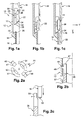
- an injection device 10 comprises a body 12 for receiving an implant, this body 12 comprising a distal end 14, to which is fixed, permanently in this example, an injection needle 16, intended to be depressed in the body of a subject.
- the injection device further comprises a piston 18, the piston 18 comprising a rod, whose proximal end is provided with a pusher (not shown), and the distal end is provided with a thrust surface 20.
- the piston 18 may be made in several segments, as in the case of the third and fourth embodiments.
- the device 10 is intended to receive an implant 22 in the solid or semi-solid state.
- the implant 22 is a single block, but it could be composed of several dissociated tablets superimposed on each other.
- the needle 16 is hollow, it has a diameter of 2 mm, and a length of about 40 mm. It is intended to deposit the implant 22 at a depth of about 10 mm from the surface of the subject's skin.
- the implant 22 is particularly fragile or deformable, it is intended to dissolve in the body of the subject, for example in a period of one month from the injection. It is made by an extrusion or injection process, and comprises a carrier material, made of PLA or PLGA, mixed with a drug.
- the receiving body 12 is arranged just upstream of the injection needle 16. Furthermore, the device 10 comprises viewing means 17, for checking the presence of an implant 22 in the device. These means 17 are, for example, a lumen formed in the receiving body 12, arranged so that the implant 22 can be seen when it is received in the device, in a manner similar to that shown in FIG. figure 1a .
- the upstream direction is designated with reference to the direction of injection of the implant 22.
- the body 12 is arranged upstream of the needle 16, that is to say that it is arranged between the needle 16 and the proximal end (end opposite the needle) of the device 10.
- the device 10 further comprises means 26 for retaining the implant 22 in the receiving body 12, these means being able to assume an activated position, visible on the figure 1a , and a disabled position, visible on the figure 1c .
- the retaining means are a retaining element 26, generally tubular openwork.
- the element 26 is slidably mounted inside the receiving body 12.
- This element 26 comprises a tubular housing 28 intended to receive the implant 22.
- This housing 28 is configured so as not to exert substantially stress on the implant 22 when received in the element 26, that the retaining means are in the activated position or in the deactivated position.
- the retaining means comprise a proximal end 30 and a distal end 32.
- the distal end 32 carries a stop 34 distally retaining the implant, which can take an activated position of restraint, visible on the figure 1a , and a disabled hold position, visible on the figure 1c .
- the retaining stop 34 extends in the transverse direction Y of the device 10, this direction Y being perpendicular to the longitudinal direction X of the device 10.
- the retaining stopper 34 when it is in the activated position, is configured to act in response to the weight of the implant 22 when the device 10 is in the vertical position, the needle 16 downward, as shown in the figures, to prevent the implant 22 passing through the needle 16, under the effect of gravity, when the device is in the position illustrated on the figure 1a .
- this stop 34 is arranged below the implant 22, more precisely between the implant 22 and the proximal end 36 of the needle.
- the stop 34 in its activated position, therefore holds the implant 22 in the housing 28, upstream of the needle 16.
- the distal end 32 of the retaining means 26 is movable between an activated position, visible on the figure 1a , and a disabled position visible on the figure 1c , for example by means of at least one elastic tab carried by this end 32, this tab carrying the stop 34.
- the device 10 further comprises means for deactivating the distal retaining means 34.
- deactivating means comprise a ramp 38, formed on the distal end of the retaining element 26, secured to the stop 34, this ramp being intended to cooperate with a ramp 40 formed on the inner distal end of the receiving body 12, so that when the retainer 26 is in the activated position illustrated on the figure 1a , the displacement of this element 26 in the direction X generates a cooperation of the ramps 38, 40, so that the distal retaining stop 34 takes its deactivated position, visible on the figure 1 vs.
- the proximal end 30 of the retaining element also has a proximal retaining stop 42 for retaining the implant in the housing 28 when the device 10 is in a vertical position, the needle 16 being upward (position opposite to that schematized on the figure 1a ).
- the abutment 42 extends in the transverse direction Y of the device 10.
- This abutment 42 is carried by one or more elastic tabs carried by the proximal end 30 of the retaining element 26.
- the end 30 is also intended to to be traversed by the piston 18, and comprises a surface 44, forming a ramp and intended to cooperate with a frustoconical surface 46 of the distal end of the piston 18.
- the ramp 44 is intended first to form a stop for the distal end of the piston 18, as can be seen on the figure 1b , then to deviate radially by elastic deformation, when the element 26 is at the end of travel in the receiving body 12.
- the means 44, 46 are means for deactivating the retaining stop 42.
- the retaining means 26 are configured so as not to exert stress on the implant 22.
- these means 26 exert a pressure on the implant 22, this pressure does not exceed a certain dependent force fragility or deformability of the implant. According to the implant, this force does not exceed 1 Newton, or does not exceed 20 Newton, so that the pressure is not likely to damage or to swell the implant 22.
- the element 26 is retained in the position illustrated on the figure 1a thanks to means for holding the element 26 in the receiving body 12.
- This maintenance results for example from a slight friction between the element 26 and the receiving body 12, this friction being erasable when the user of the device 10 exerts a force of push on the piston 18, as can be seen on the figure 1b , so that the element 26 is able to move in the direction X when pressing the piston 18.
- the retaining means 26 are in the activated position, the retaining abutments 34, 42 holding the implant inside the housing 28.
- the implant 22 is retained upstream of the needle. injection 16, and one can check its presence through means 17 for checking the presence of the implant.
- the element 26 is frictionally retained in the body 12 according to the position illustrated in FIG. figure 1a , thanks to the holding means described above.
- the needle 16 is positioned to be at least partially embedded in the body of the subject.
- the needle 16 of the figure 1a is fully sunk into the body of the subject, i.e., at a depth, relative to the skin surface of the subject, corresponding to the depth at which the implant 22 is to be placed, by
- the distal end of the needle 16 is 10 mm from the skin of the subject. Note that, even if the needle 16 is fully sunk into the skin, it is nevertheless possible to check the presence of the implant 22 by the means 17.
- the implant 22 is then released, so as to introduce it firstly into the needle 16 (as can be seen in FIG. figure 1c ) then in the skin of the subject.
- the user of the implant device 10 presses on the pusher of the piston 18, which has the effect of moving it in the longitudinal direction X, downwards.
- the abutment surface 46 of the piston rests on the abutment surface 44, which has the effect of displacing the retaining element 26 in the X direction, as can be seen in FIG. figure 1 b.
- the friction force exerted by the holding means of the element 26 in the body 12 is less than the thrust exerted by the piston 18 on the abutment surface 44, so that the element 26 moves in the X direction when the piston 18 is pressed.
- the ramps 38 and 40 cooperate, which has the effect of radially spacing the elastic tabs of the distal end 32, and in particular the retaining stop 34.
- This retaining stop 34 being spaced from the central axis of the injection device 10, it is in the deactivated position, so that it no longer ensures the retention of the implant 22 in the housing 28.
- the additional thrust of the piston 18 by the user generates the deformation of the proximal end 30 of the retaining element 26.
- the surface 46 of the piston cooperates with the ramp 44 which is deformed, so as to let the piston 18 pass through the retaining element 26.
- the piston 18 can thus push the implant 22 so as to introduce it into the needle 16, as can be seen on the figure 1c .
- the implant 22 is in the needle, and can then be injected into the body of the subject.
- the various deactivation means on the one hand the ramps 38, 40, on the other hand the ramps 44, 46, are triggered automatically, only once the needle 16 is depressed in the body of the subject.
- These deactivation means are triggered by the piston 18, more precisely by the passage of the piston from an initial position, visible on the figure 1a , at a final position, visible on the figure 1c .
- the deactivation means 38, 40; 44, 46 act directly on the retaining means 26, more precisely by cooperation between the receiving body 12 and the retaining element 26 on the one hand, and between the piston 18 and the retaining element 26 on the other. go. Consequently, these deactivation means do not act directly on the implant 22, so that there is no stress on the implant to deactivate the retaining means.
- the element 26 is held in the receiving body 12 by friction between the element 26 and the body 12.
- the retaining means 26 of this embodiment comprise, at their proximal end 30, four elastic tabs.
- Two of the diametrically opposed elastic tabs 47 are provided with lugs 48 on their outer surface, these lugs being intended to cooperate with a slot 49 made in the receiving body 12, as can be seen in FIG. figure 2b .
- These means 48, 49 constitute a high positioning stop of the element 26, intended to ensure its maintenance in an initial position similar to that of the figure 1a , by a light snap.
- the retaining element is a generally tubular element 26, the distal end 32 and proximal 30 of which comprise elastic tabs.
- the retaining means can take a multiplicity of other forms.
- this retaining element 26 could have a generally frustoconical shape, the diameter of its distal end 32 being greater than the diameter of its proximal end 30, so as to guarantee more safely the respective cooperation of the elements 38, 40 , 44, 46.
- this element 26 is not necessarily a separate part from the other parts of the implant device, the retaining means can be provided on one or more parts of the injection device 10 having another function. that the retention of the implant 22.
- injection device described in the foregoing may be a retro-injection device, as will be described later.
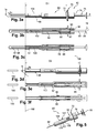
- the device 60 comprises an injection needle 62, covered, before the beginning of the use of the device 60, by a protective cap 64.
- the device 60 further comprises an intermediate body 66 and protection means 68, hereinafter referred to as "protective sheath 68", intended to cover the needle after use of the device, as can be seen in the figures 3d to 3f .
- the intermediate body 66 is external, and the sheath 68 is arranged inside the intermediate body 66, coaxially with respect to the longitudinal axis X of the device.
- the sleeve 68 has two parts, namely a distal portion 67, providing the protection function of the needle when the device is in the safety position, and a proximal portion 69, attached to the distal portion 67 , in particular ensuring a function of maintaining the sleeve in the injection position, and also keeping the sleeve in the safety position.
- the intermediate body 66 carries gripping means 70 of the device.
- the gripping means 70 comprise a stop 72 of the user's finger support, in particular of the index and major of the user.
- the gripping means 70 comprise a flange of revolution formed projecting from the intermediate body 66, near its proximal end 74.
- the device 60 further comprises a piston 76.
- the piston 76 comprises a pusher 78, intended to serve as a support for the thumb of the user, a proximal portion 80, and a distal portion 82, separable from the proximal portion 80.
- the piston 76 further comprises means 84 of FIG. release of return means, such as this is described hereinafter, these means 84 comprising a funnel shape formed between the proximal portion 80 and the pusher 78, intended to form a ramp when the piston is moved in the direction illustrated by the arrow 86.
- the device 60 further comprises return means 88, arranged between the intermediate body 66 and the sheath 68, being compressed when the device 60 is in the injection position, and can take an extended position, or rest, when the device is in a safe position, as can be seen on the figures 3d to 3f .
- the means 88 are a compression spring.
- the means 88 are maintained in the compressed state, in the injection position, by means of a distal stop 90, formed on the sheath 68, and a proximal stop 92, formed on the intermediate body 66.
- the distal stop 90 of the sheath is movable in translation to a safety position.
- the stop 90 also ensures a locking function of the sleeve 68 in the safety position, cooperating by snapping with means such as elastic tabs 94 with radial clearance, carried by the intermediate body 66.
- the sheath 68 is held in the injection position by means of retractable lugs 96 formed on its proximal portion 69, more precisely in the vicinity of the proximal end of this proximal portion 69.
- the proximal portion 69 also comprises means 98 for releasing return means 88, intended to cooperate with the means 84 of the piston 76.
- the sheath 68 and the intermediate body 66 together form, at their distal end, a receiving body of one (or more) implant 100, arranged upstream of the needle 62, intended to be injected into the body of a patient.
- the device 60 further comprises means 102 for retaining the implant 100 in the receiving body.
- the retaining means 102 ensure their retaining function by means of flexible fingers exerting a slight pressure on the implant 102. Nevertheless, these retaining means 102 may be replaced by retaining means such as presented above, for example by the retaining means 26, deactivatable by deactivation means so as not substantially to exert stress on the implant 100.
- the intermediate body 66 further comprises verification means 104, composed in this example of a window formed in the body 66, to show that the implant 100 is effectively retained by the retaining means 102.
- the implant 100 is present in the device, its presence being verified by the means 104.
- the injection begins with a withdrawal of the protective cap 64, so as to reveal the needle 62, so that the user of the device makes it penetrate into the body of the patient in which it is desired to inject the implant 100.
- the user grasps the device 60 between his index finger and his major finger, these two fingers resting on the gripping means 72, the thumb of the user being called to push on the pusher 78 in the direction of the arrow 86.
- the needle is completely discovered before being introduced into the patient's body, so that the user can see precisely what he is doing, and manually control the depression of the needle, as for a liquid injection device.
- the user pushes on the piston 76, by pressing the pusher 78.
- the displacement of the pusher 78 causes the movement of the proximal portion 80 and the distal portion 82 of the piston, which itself causes the displacement of the implant 100 in the needle 62.
- the piston 76 arrives at a position in which the means 84 are able to cooperate with the means 98. More specifically, the ramp 84 of the piston 76 causes the radial spacing of the ramp 98 of the sheath 68, this spacing causing the retraction pins 96, thus the release of the return means 88.
- This displacement has the effect of moving the sheath 68 towards the direction 86, which causes, on the one hand, the displacement of the portion 82 of the piston, previously secured to the sheath 68 (by friction or snapping), inside the needle, in order to hold the implants in place, and secondly the establishment of the position of safety by the sheath 68, visible on the figures 3d to 3f so that the sleeve 68 can cover the needle 62 as it is withdrawn from the patient's body. Once the needle is completely withdrawn, the sleeve 68 covers it completely, and the stops 90 cooperate with the means 94 of the body 66, so as to lock the device in the safety position. Because the portion 82 of the piston automatically pushes on the implant, under the effect of the release of the sheath, to maintain it in the body of the user, it is called automatic back-injection.
- the retro-injection can be, alternatively, manual.
- the piston 76 is in one piece, not securable to the sheath 68, and the injection of the implant takes place before the retraction of the lugs 96.
- the user can perform a slight backward movement of the device 60, which generates a start of withdrawal of the needle, and thus leaves room in the patient's body for introduce the implant 100 without constraint.
- the user can press again on the pusher 78, which allows the piston 76 (not integral with the sleeve) to push the implant 100 in the body of the patient. Then, the additional depression of the pusher 78 causes the retraction of the lugs 96, thus the automatic release of the protection means 68.
- the distance between the gripping means 70 and the skin of the patient 106 has been increased by the value D 1 , when the device is in the injection position at the value D 2 , when the device is in the safety position.
- the device 60 allows the retro-injection of the implant 100, that is to say that the implant 100 is injected, more precisely remains in position in the body of the patient, at the time of removal of the needle. 62 outside the body of the patient.
- automatic protection of the needle is provided by the sheath 68, at the time of its withdrawal, the needle not being left uncovered, while offering the possibility to the user to manually control the withdrawal.
- the user's fingers By removing the needle 62 from the skin 106 of the patient, the user's fingers move, moving backwards. If the user does not control his fingers, they are driven by the movement of the return means 88 which trigger the exit of the sleeve 68 from the intermediate body 66. In this case, the removal of the needle is done automatically, without control user's Guide. Nevertheless, the user can manually control the withdrawal of the needle, by controlling the movement of the means 88 via the means 70. Indeed, the user can for example slow down or stop the movement of the means 88, by exerting a force on the gripping means 70 against the force exerted by the return means 88.
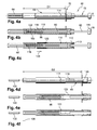
- the feedback device 60 illustrated on the Figures 4a to 4f has a different structure of the device Figures 3a to 3f , but a similar operation.
- the sleeve 68 is disposed outside, and the intermediate body 66 is arranged, coaxially with respect to the axis X, inside the sleeve 68.
- the sleeve 68 carries, at its proximal end, retractable means 110, composed in the example of two elastic tabs 110, each provided with retractable lugs 112, intended to cooperate with the intermediate body 66. retractable tabs 110 further include ramps 113, intended to cooperate with the piston 72.
- the sleeve 68 also comprises means 114 in the example for cooperating with the intermediate body 66.
- the sheath 68 comprises a stop 115 intended to serve as a support for the return means 88.
- the intermediate body 66 comprises a body 116 for receiving the implant 100, the implant being retained by the retaining means 102.
- the intermediate body 66 comprises a stop 118 intended to serve as a support for the proximal end of the return means 88.
- the intermediate body 66 is composed of two parts, namely a proximal portion 120 , carrying the gripping means 70, attached to a distal portion 122, comprising the receiving body of the implant 100.
- the intermediate body 66 is provided with means 123 for locking the sheath 68 in the safety position, in this case pins 123 intended to cooperate with the slots 114.
- the pusher 78 of the piston 72 is provided with means 124 for releasing the locking means 112, thanks to a cap shape of the pusher 78.
- the user begins by removing the protective cap 64 and then introducing the needle 62 into the body of the patient. Then, the user presses the pusher 78, which has the effect of moving the rods 80 and 82 of the piston 72, so the implant 100 which is introduced into the distal end of the needle 62.
- the release means 124 cooperate with the elastic ramp 113, so as to radially move the elastic tabs 110 and thus retract the lugs 112. Once the lugs 112 retracted, the return means 88 are released and may extend in the direction indicated by the arrow 126.
- This release of return means 88 has the effect of moving the intermediate body 66 in the direction of the arrow 126, and thus to protect the needle 62 by the sheath 68 , as can be seen from the Figures 4d to 4f . Then, the device is maintained in the safety position, by means of cooperation means 114 and 123.
- the user can manually control the removal of the needle from the skin of the patient 106.
- the device 60 includes means 107 for indicating the distal grip of the device, the distal gripping being intended to facilitate the insertion of the needle into the needle. patient's body.
- These means 107 are arranged on the body 66, at near its distal end. They can be composed of a visual indication, a protuberance (which is the case on the figure 5 ), or a grainy surface. They are intended to indicate to the user a distal zone that the user can use to implement the injection.
- indication means 107 may be provided on all other embodiments. In the case of the embodiment of figures 4 the means 107 could be provided on the sheath 68.
- the device 60 Before starting to prick the patient, the device 60 is in the configuration of the figure 5 .
- the user grasps the device 60 by its distal portion, preferably holding the indication zone 107 between the fingers of his right hand if he is right-handed. Indeed, it may be more convenient for the user to introduce the needle by holding the device 60 at this area 107, because the device 60 may be relatively long (it may be for example a length of 200 mm between the end of the needle 62 and the pusher 78). Specifically, the user holds with his right hand the proximal end 108 of the indication zone 107.
- the user can pinch the patient's body, to create a hard surface for introduce the needle. Once the needle is fully depressed in the patient's body, the user can stop pinching the patient's body, and seize, with his left hand released, the distal end 109 of the zone 107, so as to release his right hand which releases the end 108 and can seize the gripping means 70 to activate the piston 76 and proceed to the steps of injection and withdrawal of the needle.
- the piston 76 is rather in one part, and the retro-injection is preferably manual.
- the embodiments of the retro-injection device 60 may take other forms than those described. In particular, the embodiments may be combined with any one of the other embodiments.
- the devices of the third fourth and fifth embodiments are implant retro-injection devices, preferably automatic retro-injection, but can also implement manual retro-injection, as has been described.
- the invention proposes to manually control the movement of the means. protection 68, from the gripping means 70.
- the user himself proceeds to the injection of the implant, by retracting the needle inside the body of the patient and exerting pressure on the piston before the automatic release of the means of protection.
Abstract
Description
La présente invention concerne le domaine technique de l'injection d'un ou plusieurs implants dans le corps d'un sujet. Plus précisément, mais non exclusivement, l'invention concerne l'injection intra-musculaire ou sous-cutanée d'un (ou plusieurs) composé pharmaceutique à l'état solide ou semi-solide, que l'on désigne "implant" dans la suite. Le sujet peut être un mammifère, notamment un être humain. On le désignera "sujet" ou "patient" dans la suite. Cet implant est injecté périodiquement, par exemple tous les mois, dans le corps du sujet, à environ 10 mm (millimètres) de la surface de la peau du sujet, cet implant se dissolvant ensuite dans le corps du sujet, au cours du mois. Selon une autre application possible, l'implant est une puce électronique utilisée pour l'identification d'un être vivant.The present invention relates to the technical field of injecting one or more implants into the body of a subject. More specifically, but not exclusively, the invention relates to intramuscular or subcutaneous injection of one (or more) pharmaceutical compound in the solid or semi-solid state, which is designated "implant" in the after. The subject may be a mammal, including a human being. It will be called "subject" or "patient" in the following. This implant is injected periodically, for example every month, into the body of the subject, about 10 mm (millimeters) from the surface of the skin of the subject, this implant then dissolving in the body of the subject, during the month. According to another possible application, the implant is an electronic chip used for the identification of a living being.
On connaît déjà du document
Un inconvénient d'un tel dispositif réside dans le fait que la déformation des doigts flexibles engendre une mise sous contrainte des comprimés. En effet, les comprimés subissent la compression à la fois du piston sur lequel l'utilisateur appuie et des doigts flexibles qui exercent une certaine résistance avant de s'effacer. Or, pour certains implants, il peut être problématique de les mettre sous contrainte. En effet, certains implants sont particulièrement fragiles ou facilement déformables, du fait qu'ils comprennent des matériaux destinés à se dissoudre dans le corps du sujet. Ainsi, la pression exercée sur ces implants peut les endommager. En outre, dans le cas d'un implant déformable, la pression exercée dessus fait augmenter son diamètre, si bien que l'implant reste bloqué à l'intérieur du dispositif.A disadvantage of such a device lies in the fact that the deformation of the flexible fingers causes stressing of the tablets. Indeed, the tablets undergo the compression of both the piston on which the user presses and flexible fingers that exert some resistance before fading. However, for some implants, it can be problematic to put them under stress. Indeed, some implants are particularly fragile or easily deformable, because they include materials intended to dissolve in the body of the subject. Thus, the pressure exerted on these implants can damage them. In addition, in the case of a deformable implant, the pressure exerted on it increases its diameter, so that the implant remains blocked inside the device.
La présente invention vise notamment à fournir un dispositif garantissant que les implants injectés dans le corps du sujet sont intacts.The present invention aims in particular to provide a device ensuring that the implants injected into the body of the subject are intact.
A cet effet, l'invention a pour objet un dispositif d'injection d'un implant, comportant :
- un corps de réception de l'implant agencé en amont d'une aiguille d'injection,
- des moyens de retenue de l'implant dans le corps de réception,
- des moyens de désactivation des moyens de retenue,
- les moyens de retenue étant configurés de façon à ne pas exercer de contrainte sur l'implant.
Ainsi, on prévoit un dispositif garantissant que l'implant ne sera pas détérioré ni déformé à la suite d'une contrainte. En effet, le dispositif comprend des moyens de désactivation aptes à empêcher les moyens de retenue d'abîmer l'implant lorsqu'il est introduit dans l'aiguille.
On comprendra que "ne pas exercer de contrainte sur l'implant" consiste à ne pas lui faire subir de force susceptible de l'endommager. Ainsi, le dispositif présenté ci-dessus peut exercer une légère pression sur l'implant, mais sans risquer de l'endommager. Par exemple, pour un implant en PLA ou PLGA (dérivés d'acides lactiques et glycoliques), on peut exercer une légère pression sur l'implant, par exemple allant jusqu'à 1 N (Newton) pour un implant très fragile ou très déformable, ou allant jusqu'à 20 N (Newton) pour un implant plus résistant ou moins déformable, sans le dégrader.
Parmi les avantages de l'invention, on notera que les moyens de retenue permettent de retenir l'implant dans le corps de réception tant que l'aiguille n'est pas enfoncée dans le corps du sujet et qu'aucune pression n'a été exercée sur la tige de piston. Ainsi, le dispositif garantit à l'utilisateur que l'implant ne risque pas de tomber accidentellement du dispositif avant que l'aiguille soit enfoncée dans le corps du sujet. II est particulièrement important de s'assurer que l'implant est bien présent dans le dispositif avant son injection, du fait que les conséquences de la non injection d'un implant, l'utilisateur croyant par erreur l'avoir injecté, peuvent être considérables dans le domaine médical. En outre, il est avantageux que l'implant soit retenu dans des moyens agencés en amont de l'aiguille, et non dans l'aiguille, du fait que l'utilisateur du dispositif peut s'assurer, au moment où l'aiguille est enfoncée dans le corps du sujet, et de préférence même lorsqu'elle est totalement enfoncée, que l'implant est toujours dans le dispositif. Or, si l'implant avait été retenu à l'intérieur de l'aiguille, et non en amont de l'aiguille, l'utilisateur ne pourrait pas vérifier, une fois que l'aiguille est enfoncée dans le corps du sujet, que l'implant est toujours présent dans le dispositif, du fait qu'il ne peut plus voir l'aiguille. Cet avantage est notable du fait qu'un implant mal retenu dans le dispositif pourrait aisément tomber du dispositif, juste avant l'injection, au moment où l'aiguille est dirigée vers le bas.
L'invention peut en outre comporter l'une ou plusieurs des caractéristiques suivantes. - Les moyens de désactivation des moyens de retenue sont déclenchés de façon automatique, une fois que l'aiguille est, au moins partiellement, en position d'enfoncement, c'est-à-dire enfoncée dans le corps du sujet. Ainsi, l'utilisateur du dispositif n'a pas besoin d'effectuer une manoeuvre spécifique pour activer la libération de l'implant retenu dans le dispositif, ce qui facilite la manipulation du dispositif au cours de l'injection. En particulier, l'utilisateur n'a pas besoin de changer de main pour mettre en oeuvre le transfert de l'implant dans l'aiguille, le dépôt de l'implant dans le corps du sujet et le retrait de l'aiguille, il ne fait donc pas de geste brusque qui serait douloureux pour un patient.
- Les moyens de désactivation agissent directement sur les moyens de retenue. En d'autres termes, les moyens de désactivation n'agissent pas sur les moyens de retenue par l'intermédiaire de l'implant, si bien que l'on évite les risques d'endommager l'implant.
- Le dispositif comprend un piston et les moyens de désactivation sont déclenchés par ce piston, plus précisément par le passage du piston à une position prédéterminée. Le déclenchement automatique de la désactivation des moyens de retenue se fait donc par exemple lorsque l'utilisateur appuie sur le piston afin d'injecter l'implant, sans qu'il n'ait à faire d'autre geste que d'appuyer sur le piston.
- Les moyens de retenue comportent une butée de retenue de l'implant, pouvant prendre une position activée de retenue avant que l'aiguille ne soit dans la position d'enfoncement, c'est-à-dire avant que l'aiguille ne commence à être enfoncée dans le corps du sujet, et une position désactivée une fois que l'aiguille est dans la position d'enfoncement, c'est-à-dire une fois que l'aiguille est, au moins partiellement, enfoncée dans le corps du sujet. De préférence, cette butée de retenue agit en réaction du poids de l'implant, afin d'empêcher l'implant de passer dans l'aiguille, sous l'effet de la gravité, lorsque le dispositif est dans la position verticale. Cette butée de retenue peut prendre la forme d'une butée s'étendant dans une direction transversale du dispositif, en dessous de l'implant, en particulier entre l'implant et l'extrémité proximale de l'aiguille.
- La butée de retenue est portée par une patte élastique.
- Les moyens de retenue sont portés par un élément de retenue, et la désactivation comprend d'une part une coopération entre l'élément de retenue et le corps de réception de l'implant, et d'autre part une coopération entre l'élément de retenue et le piston.
- Les moyens de désactivation sont aptes à mettre en oeuvre un écartement radial des moyens de retenue. Ainsi, la butée de retenue peut passer dans sa position désactivée à la suite d'un écartement radial, généré par exemple par une rampe ménagée dans le corps de réception de l'implant, la rampe coopérant avec les moyens de retenue lorsque le piston du dispositif est déplacé.
- Le dispositif comporte des moyens de vérification, configurés de façon que l'implant soit visible par un utilisateur lorsqu'il est retenu par les moyens de retenue, notamment lorsque l'aiguille est dans une position non visible par l'utilisateur, par exemple complètement enfoncée dans le corps du sujet.
- a receiving body of the implant arranged upstream of an injection needle,
- means for retaining the implant in the receiving body,
- means for deactivating the retaining means,
- the retaining means being configured so as not to exert stress on the implant.
Thus, there is provided a device ensuring that the implant will not be damaged or deformed as a result of stress. Indeed, the device comprises deactivating means adapted to prevent the retaining means from damaging the implant when it is introduced into the needle.
It will be understood that "not to exert stress on the implant" consists in not subjecting it to a force liable to damage it. Thus, the device presented above can exert a slight pressure on the implant, but without the risk of damaging it. For example, for a PLA or PLGA implant (lactic and glycolic acid derivatives), it is possible to exert a slight pressure on the implant, for example up to 1 N (Newton) for a very fragile or highly deformable implant. , or up to 20 N (Newton) for a stronger or less deformable implant, without degrading it.
Among the advantages of the invention, it should be noted that the retaining means make it possible to retain the implant in the receiving body as long as the needle is not sunk into the subject's body and no pressure has been applied. exerted on the piston rod. Thus, the device ensures the user that the implant is not likely to accidentally fall out of the device before the needle is sunk into the body of the subject. It is particularly important to ensure that the implant is present in the device before injection, since the consequences of non-injection of an implant, the user mistakenly thinking of having injected it, can be considerable. in the medical field. In addition, it is advantageous that the implant is retained in means arranged upstream of the needle, and not in the needle, because the user of the device can be sure, at the moment when the needle is embedded in the body of the subject, and preferably even when fully depressed, that the implant is still in the device. However, if the implant had been retained inside the needle, and not upstream of the needle, the user could not check, once the needle is inserted into the body of the subject, that the implant is still present in the device, because it can no longer see the needle. This advantage is notable because a poorly retained implant in the device could easily fall out of the device just before the injection, when the needle is pointing downwards.
The invention may further include one or more of the following features. - The means for deactivating the retaining means are triggered automatically, once the needle is at least partially in the depressed position, that is to say, pressed into the body of the subject. Thus, the user of the device does not need to perform a specific maneuver to activate the release of the implant retained in the device, which facilitates the manipulation of the device during the injection. In particular, the user does not need to change hands to the transfer of the implant into the needle, the deposit of the implant in the body of the subject and the withdrawal of the needle, it does not make a sudden gesture that would be painful for a patient.
- The deactivation means act directly on the retaining means. In other words, the deactivation means do not act on the retaining means via the implant, so that the risk of damaging the implant is avoided.
- The device comprises a piston and the deactivation means are triggered by this piston, more precisely by the passage of the piston to a predetermined position. The automatic triggering of the deactivation of the retaining means is therefore done for example when the user presses on the piston to inject the implant, without having to make any other gesture than to press the piston.
- The retaining means comprise an implant retaining stop, which can take an activated retaining position before the needle is in the depressing position, i.e. before the needle starts to to be depressed into the body of the subject, and a deactivated position once the needle is in the depressing position, i.e. once the needle is at least partially inserted into the body of the subject. subject. Preferably, this retaining stopper acts in response to the weight of the implant, to prevent the implant from passing into the needle, under the effect of gravity, when the device is in the upright position. This retaining stop may take the form of a stop extending in a transverse direction of the device, below the implant, in particular between the implant and the proximal end of the needle.
- The retaining stop is carried by an elastic tab.
- The retaining means are carried by a retaining element, and the deactivation comprises on the one hand a cooperation between the retaining element and the receiving body of the implant, and on the other hand a cooperation between the retaining element. restraint and piston.
- The deactivation means are able to implement a radial spacing of the retaining means. Thus, the retaining stop can pass into its deactivated position as a result of a radial spacing, generated for example by a ramp formed in the receiving body of the implant, the ramp cooperating with the retaining means when the piston of the device is moved.
- The device comprises verification means, configured so that the implant is visible to a user when it is retained by the retaining means, in particular when the needle is in a position not visible to the user, for example completely buried in the body of the subject.
La présente invention propose en outre un dispositif de rétro-injection d'un implant. La rétro-injection consiste à injecter l'implant au cours du retrait de l'aiguille. Les inventeurs proposent de fournir un dispositif agencé de telle sorte que l'utilisateur du dispositif puisse contrôler manuellement le retrait de l'aiguille hors du corps d'un patient. En effet, on cherche à éviter un retrait automatique de l'aiguille, sous l'action unique d'un ressort, du fait que ce retrait automatique peut être douloureux pour le patient pour notamment deux raisons : l'utilisateur qui injecte l'implant peut ne pas être habitué à utiliser un dispositif de rétro-injection, et il arrive en outre que l'aiguille du dispositif de rétro-injection soit particulièrement longue.The present invention further provides a device for retro-injecting an implant. The retro-injection consists of injecting the implant during the removal of the needle. The inventors propose to provide a device arranged such that the user of the device can manually control the removal of the needle from the body of a patient. Indeed, it seeks to avoid automatic withdrawal of the needle, under the single action of a spring, because this automatic withdrawal can be painful for the patient for two reasons in particular: the user who injects the implant may not be used to using a retro-injection device, and it also happens that the needle of the retro-injection device is particularly long.
A cet effet, l'invention a pour objet un dispositif de rétro-injection d'implant, comportant :
- des moyens de préhension du dispositif par un utilisateur,
- une aiguille d'injection,
- des moyens de protection de l'aiguille, aptes à prendre une position d'injection, laissant l'aiguille découverte, et une position de sécurité, recouvrant l'aiguille après l'utilisation du dispositif,
- des moyens de rappel aptes à entraîner les moyens de protection depuis leur position d'injection jusqu'à leur position de sécurité,
- le mouvement des moyens de rappel étant contrôlable par l'utilisateur.
Ainsi, on propose un dispositif dans lequel les moyens de protection, généralement un fourreau protecteur, peuvent prendre leur position de sécurité, de façon à empêcher l'aiguille de rester découverte après avoir été introduite dans le corps du patient. Cette position de sécurité est prise de préférence de façon automatique, par exemple par libération des moyens de rappel lorsque le piston du dispositif arrive en fin de course, ces moyens de rappel provoquant un déplacement relatif de l'aiguille et du fourreau, de façon que le fourreau puisse protéger l'aiguille. On propose un mouvement relatif du fourreau et de l'aiguille déclenché de façon automatique sans pour autant que le retrait de l'aiguille hors du corps du patient soit mis en oeuvre par les moyens de rappel seuls, sans possibilité de contrôle du mouvement du dispositif par l'utilisateur. Ainsi, l'utilisateur peut grâce à ce dispositif contrôler le mouvement des moyens de rappel en s'opposant au moins en partie à leur libération, de préférence à partir des moyens de préhension, si bien que l'utilisateur peut stopper le mouvement des moyens de rappel s'il le souhaite, ou encore le ralentir ou l'accélérer. Les moyens de préhension comprennent généralement une butée d'appui des doigts de l'utilisateur, de préférence d'appui de l'index et le majeur de l'utilisateur, agencée à l'extrémité proximale du dispositif. Une fois que l'aiguille est enfoncée dans le corps du patient, le retrait de l'aiguille hors du corps peut être mis en oeuvre, au moins en partie, par un mouvement de recul effectué par les doigts de l'utilisateur, de sorte que la distance entre la peau du patient et les moyens de préhension augmente au cours du retrait de l'aiguille.
Un tel dispositif de rétro-injection propose à l'utilisateur un fonctionnement similaire à celui d'un dispositif d'injection de liquide, muni d'une seringue et d'un fourreau protecteur déclenché automatiquement, tout en offrant les spécificités techniques dues à un dispositif de rétro-injection d'implant sous forme solide ou semi-solide, notamment les moyens nécessaires pour injecter l'implant au cours du retrait de l'aiguille. On notera que la rétro-injection d'implant a pour avantage de ne pas exercer de contrainte sur l'implant au moment où ce dernier sort de l'aiguille pour rester dans le corps du patient, à la différence d'une injection simple où le produit (par exemple un médicament liquide) est poussé à travers la peau du patient. Dans un cas d'injection simple, si l'implant est fragile, il est cassé lorsqu'il est poussé à travers la peau. A la différence, au cours de la rétro-injection, l'implant ne traverse pas la peau, il remplit un vide laissé par l'aiguille au moment de son retrait : l'implant est amené jusqu'à l'extrémité proximale de l'aiguille en subissant le moins de contrainte possible, puis, le mouvement de retrait de l'aiguille hors du corps de patient s'effectue, en laissant l'implant dans le corps du patient, à la même profondeur que lorsqu'il était à l'extrémité distale de l'aiguille. Lorsque ce retrait de l'aiguille est effectué de façon automatique, sous l'action d'un ressort, l'utilisateur peut ne pas contrôler manuellement le retrait de l'aiguille (du fait du mécanisme intérieur de rétro-injection, non accessible depuis l'extérieur du dispositif), ce qui peut le perturber s'il est habitué à utiliser des dispositifs d'injection de médicament liquide. Or, si l'utilisateur n'est pas habitué à utiliser un dispositif de rétro-injection, son geste d'utilisation du dispositif peut être maladroit, et donc douloureux pour le patient. Grâce à l'invention, l'utilisateur peut contrôler manuellement le retrait de l'aiguille hors du corps du patient, comme pour certains dispositifs d'injection de médicament sous forme liquide. Le dispositif de rétro-injection a donc un fonctionnement que l'utilisateur connaît. On notera que le dispositif de rétro-injection selon l'invention assure de préférence une rétro-injection automatique, c'est-à-dire que le transfert de l'implant(s) de l'aiguille vers le patient se fait automatiquement en un seul geste lors de la rétractation de l'aiguille, mais que la rétro-injection peut également être, au moins en partie, manuelle. En effet, au moment où l'implant est positionné à l'extrémité distale de l'aiguille, on peut prévoir que le retrait de l'aiguille, du moins le début du retrait de l'aiguille, se fasse de façon manuelle, par un mouvement de recul des doigts de l'utilisateur. Ce début de retrait de l'aiguille crée un espace dans le corps du patient, dans lequel on peut introduire l'implant, sans exercer de contrainte sur lui, en appuyant sur le piston. Puis, la pression supplémentaire sur le piston peut ensuite libérer automatiquement les moyens de protection de l'aiguille et la suite du retrait de l'aiguille hors du corps du patient. Ainsi, les opérations de transfert de l'implant dans le corps du patient et de protection de l'aiguille peuvent être réalisées simultanément (rétro-injection automatique) ou de façon successive (rétro-injection manuelle).
Par ailleurs, le dispositif comporte des moyens de retenue de l'implant en amont de l'aiguille d'injection. Comme cela a été expliqué plus haut, il est particulièrement avantageux que l'implant soit retenu en amont de l'aiguille et non dans l'aiguille, du fait que l'utilisateur du dispositif peut s'assurer, au moment où l'aiguille est enfoncée dans le corps du sujet, et de préférence même lorsqu'elle est totalement enfoncée, que l'implant est toujours dans le dispositif. Par ailleurs, l'implant peut être plus facile à retenir en amont de l'aiguille que dans l'aiguille. En outre, comme la course de l'implant avant de sortir de l'aiguille est plus longue lorsqu'il est retenu en amont de l'aiguille, l'implant présente moins de risques de sortir du dispositif au moment où l'on va enfoncer l'aiguille dans le corps du patient.
La retenue en amont de l'aiguille peut être effectuée de la façon décrite ci-dessus, en utilisant des moyens de désactivation, ou bien en exerçant une légère pression sur l'implant, de façon à la retenir par frottements, par exemple au moyen de doigts flexibles.
Le dispositif de rétro-injection peut en outre comporter l'une ou plusieurs des caractéristiques suivantes. - Le dispositif comporte un piston comprenant deux parties séparables, une partie distale et une partie proximale, la partie distale étant destinée à positionner l'implant à affleurement de l'extrémité distale de l'aiguille.
- Le dispositif comporte des moyens escamotables de fixation des moyens de protection aux moyens de préhension. Ainsi, lorsque le dispositif est en position d'injection, les moyens de protection sont solidarisés aux moyens de préhension, et lorsque le dispositif est en position de sécurité, les moyens de protection sont désolidarisés des moyens de préhension. Par exemple, les moyens de fixation escamotables comprennent des moyens d'encliquetage agencés respectivement sur l'extrémité proximale des moyens de protection et sur une partie solidarisée aux moyens de préhension.
- means for gripping the device by a user,
- an injection needle,
- needle protection means, adapted to take an injection position, leaving the needle uncovered, and a safety position, covering the needle after use of the device,
- return means capable of driving the protection means from their injection position to their safety position,
- the movement of the return means being controllable by the user.
Thus, there is provided a device in which the protective means, usually a protective sheath, can assume their safe position, so as to prevent the needle from remaining uncovered after being introduced into the patient's body. This safety position is preferably taken automatically, for example by releasing the return means when the piston of the device reaches the end of stroke, these biasing means causing a relative movement of the needle and the sleeve, so that the sheath can protect the needle. It proposes a relative movement of the sleeve and the automatically triggered needle without the withdrawal of the needle from the body of the patient is implemented by the return means alone, without possibility of controlling the movement of the device by the user. Thus, the user can, thanks to this device, control the movement of the return means by at least partly opposing their release, preferably from the gripping means, so that the user can stop the movement of the means. if it wishes, or slow down or speed it up. The gripping means generally comprise a support abutment of the user's fingers, preferably bearing the index finger and the middle finger of the user, arranged at the proximal end of the device. Once the needle is depressed into the patient's body, removal of the needle from the body can be implemented, at least in part, by a recoil movement performed by the fingers of the patient. the user, so that the distance between the patient's skin and the gripping means increases during the removal of the needle.
Such a retro-injection device offers the user operation similar to that of a liquid injection device, provided with a syringe and a protective sheath triggered automatically, while offering the technical specificities due to a implant retro-injection device in solid or semi-solid form, in particular the means necessary for injecting the implant during removal of the needle. It should be noted that the implant retro-injection has the advantage of not exerting stress on the implant at the moment when the latter leaves the needle to remain in the patient's body, unlike a simple injection where the product (e.g. a liquid medicine) is pushed through the patient's skin. In a case of simple injection, if the implant is fragile, it is broken when it is pushed through the skin. In contrast, during the retro-injection, the implant does not penetrate the skin, it fills a void left by the needle at the time of its removal: the implant is brought to the proximal end of the needle. needle undergoing the least possible stress, then, the withdrawal movement of the needle out of the patient's body takes place, leaving the implant in the body of the patient, at the same depth as when it was at the distal end of the needle. When this withdrawal of the needle is performed automatically, under the action of a spring, the user may not manually control the withdrawal of the needle (due to the internal mechanism of retro-injection, not accessible since the outside of the device), which can disturb it if it is used to using liquid drug injection devices. However, if the user is not used to using a retro-injection device, his use of the device may be clumsy, and therefore painful for the patient. Thanks to the invention, the user can manually control the removal of the needle from the body of the patient, as for some drug injection devices in liquid form. The retro-injection device has a functioning that the user knows. It will be noted that the retro-injection device according to the invention preferably provides an automatic retro-injection, that is to say that the transfer of the implant (s) from the needle to the patient is automatically done. a single gesture during the retraction of the needle, but that the retro-injection can also be, at least in part, manual. Indeed, when the implant is positioned at the distal end of the needle, it can be provided that the removal of the needle, at least the beginning of the withdrawal of the needle, is done manually, by a recoil of the fingers of the user. This beginning of withdrawal of the needle creates a space in the body of the patient, in which the implant can be introduced without exerting stress on it, by pressing on the piston. Then, the additional pressure on the piston can then automatically release the means of protection of the needle and the continuation of the removing the needle from the patient's body. Thus, the transfer operations of the implant into the patient's body and the protection of the needle can be performed simultaneously (automatic reverse injection) or successively (manual reverse injection).
Furthermore, the device comprises means for retaining the implant upstream of the injection needle. As has been explained above, it is particularly advantageous for the implant to be retained upstream of the needle and not in the needle, since the user of the device can be sure, at the moment when the needle is depressed into the body of the subject, and preferably even when fully depressed, that the implant is still in the device. In addition, the implant may be easier to retain upstream of the needle than in the needle. In addition, since the stroke of the implant before leaving the needle is longer when it is held upstream of the needle, the implant has less risk of coming out of the device at the moment when one goes push the needle into the patient's body.
The retainer upstream of the needle can be carried out as described above, by using deactivation means, or by exerting a slight pressure on the implant, so as to hold it by friction, for example by means of flexible fingers.
The feedback device may further include one or more of the following features. - The device comprises a piston comprising two separable portions, a distal portion and a proximal portion, the distal portion being adapted to position the implant flush with the distal end of the needle.
- The device comprises retractable means for fixing the protection means to the gripping means. Thus, when the device is in the injection position, the protection means are secured to the gripping means, and when the device is in the safety position, the protection means are disengaged from the gripping means. For example, the retractable fastening means comprise snap-fastening means arranged respectively on the proximal end of the protection means and on a portion secured to the gripping means.
L'invention sera mieux comprise à la lecture de la description qui va suivre, donnée uniquement à titre d'exemple et faite en se référant aux dessins dans lesquels :
- la
figure 1a est une vue en coupe longitudinale partielle d'une partie d'un dispositif selon un premier mode de réalisation de l'invention, illustrant des moyens de retenue en position activée ; - la
figure 1b est une vue similaire à celle de lafigure 1 , illustrant les moyens de retenue en cours de désactivation ; - la
figure 1c est une vue similaire à lafigure 1 , illustrant les moyens de retenue en position désactivée ; - la
figure 2a est une vue de dessus de moyens de retenue d'un dispositif selon un second mode de réalisation de l'invention ; - la
figure 2b est une vue en coupe longitudinale partielle d'une partie des moyens de retenue de lafigure 2a ; - la
figure 2c est une vue en coupe longitudinale partielle d'une partie des moyens de retenue de lafigure 2a , le plan de coupe étant perpendiculaire au plan de coupe de lafigure 2b ; - la
figure 3a est une vue de côté d'un dispositif d'injection selon un troisième mode de réalisation de l'invention, le dispositif étant représenté en position d'injection ; - la
figure 3b est une vue en coupe longitudinale selon la flèche 3b de lafigure 3a ; - la
figure 3c est une vue en coupe longitudinale selon la flèche 3c de lafigure 3a ; - les
figures 3d, 3e et 3f sont des vues respectivement similaires aux vues 3a, 3b, 3c, le dispositif étant dans sa position de sécurité ; - les
figures 4a à 4f sont des vues respectivement similaires auxfigures 3a à 3f d'un dispositif d'injection selon un quatrième mode de réalisation de l'invention ; - la
figure 5 et une vue d'un dispositif selon un cinquième mode de réalisation de l'invention.
- the
figure 1a is a partial longitudinal sectional view of a portion of a device according to a first embodiment of the invention, illustrating holding means in the activated position; - the
figure 1b is a view similar to that of thefigure 1 illustrating the restraining means being deactivated; - the
figure 1c is a view similar to thefigure 1 illustrating the retaining means in the deactivated position; - the
figure 2a is a top view of means for retaining a device according to a second embodiment of the invention; - the
figure 2b is a partial longitudinal sectional view of part of the retaining means of thefigure 2a ; - the
Figure 2c is a partial longitudinal sectional view of part of the retaining means of thefigure 2a , the section plane being perpendicular to the section plane of thefigure 2b ; - the
figure 3a is a side view of an injection device according to a third embodiment of the invention, the device being shown in the injection position; - the
figure 3b is a longitudinal sectional view along thearrow 3b of thefigure 3a ; - the
figure 3c is a longitudinal sectional view along thearrow 3c of thefigure 3a ; - the
figures 3d, 3e and 3f are views respectively similar to theviews - the
Figures 4a to 4f are respectively similar views toFigures 3a to 3f an injection device according to a fourth embodiment of the invention; - the
figure 5 and a view of a device according to a fifth embodiment of the invention.
Comme on peut le voir sur les
Le dispositif 10 est destiné à recevoir un implant 22 à l'état solide ou semi-solide. Dans cet exemple, l'implant 22 est un unique bloc, mais il pourrait être composé de plusieurs comprimés dissociés, superposés les uns aux autres.The
Selon l'exemple décrit, l'aiguille 16 est creuse, elle a un diamètre de 2 mm, et une longueur d'environ 40 mm. Elle est destinée à déposer l'implant 22 à une profondeur d'environ 10 mm de la surface de la peau du sujet. L'implant 22 est particulièrement fragile ou déformable, il est destiné à se dissoudre dans le corps du sujet, par exemple dans une durée de un mois à compter de son injection. Il est réalisé par un procédé d'extrusion ou d'injection, et comprend un matériau support, en PLA ou PLGA, mélangé avec un médicament.According to the example described, the
Comme on peut le constater, le corps de réception 12 est agencé juste en amont de l'aiguille d'injection 16. Par ailleurs, le dispositif 10 comporte des moyens de visualisation 17, permettant de vérifier la présence d'un implant 22 dans le dispositif. Ces moyens 17 sont par exemple une lumière ménagée dans le corps de réception 12, agencée de façon que l'on puisse voir l'implant 22 lorsqu'il est reçu dans le dispositif, de façon similaire à celle représentée sur la
Dans la présente demande, on désigne la direction amont en référence à la direction d'injection de l'implant 22. Ainsi, le corps 12 est agencé en amont de l'aiguille 16, c'est-à-dire qu'il est agencé entre l'aiguille 16 et l'extrémité proximale (extrémité opposée à l'aiguille) du dispositif 10.In the present application, the upstream direction is designated with reference to the direction of injection of the
Le dispositif 10 comporte en outre des moyens 26 de retenue de l'implant 22 dans le corps de réception 12, ces moyens pouvant prendre une position activée, visible sur la
L'extrémité distale 32 porte une butée 34 de retenue distale de l'implant, pouvant prendre une position activée de retenue, visible sur la
Le dispositif 10 comporte par ailleurs des moyens de désactivation des moyens de retenue distaux 34. Ces moyens de désactivation comprennent une rampe 38, ménagée sur l'extrémité distale de l'élément de retenue 26, solidarisée à la butée 34, cette rampe étant destinée à coopérer avec une rampe 40 ménagée sur l'extrémité distale intérieure du corps de réception 12, de façon que lorsque l'élément de retenue 26 est dans la position activée illustrée sur la
L'extrémité proximale 30 de l'élément de retenue comporte par ailleurs une butée 42 de retenue proximale, permettant de retenir l'implant dans le logement 28 lorsque le dispositif 10 est en position verticale, l'aiguille 16 étant vers le haut (position opposée à celle schématisée sur la
On notera que les moyens de retenue 26 sont configurés de façon à ne pas exercer de contrainte sur l'implant 22. En particulier, si ces moyens 26 exercent une pression sur l'implant 22, cette pression n'excède pas une certaine force dépendant de la fragilité ou de la déformabilité de l'implant. Selon l'implant, cette force n'excède pas 1 Newton, ou encore n'excède pas 20 Newton, si bien que la pression n'est pas susceptible d'endommager ou de faire gonfler l'implant 22.It will be noted that the retaining means 26 are configured so as not to exert stress on the
Par ailleurs, l'élément 26 est retenu dans la position illustrée sur la
Le fonctionnement du dispositif d'injection 10 va à présent être décrit.The operation of the
Avant d'enfoncer l'aiguille 16 dans le corps du sujet, comme on peut le voir sur la
Sur la
On procède ensuite à la libération de l'implant 22, de façon à l'introduire tout d'abord dans l'aiguille 16 (comme on peut le voir sur la
Sous la pression du piston 18, lorsque l'élément 26 arrive en fin de course à l'intérieur du corps de réception 12 (visible sur la
Comme on peut le constater, les différents moyens de désactivation, d'une part les rampes 38, 40, d'autre part les rampes 44, 46, sont déclenchés de façon automatique, uniquement une fois que l'aiguille 16 est enfoncée dans le corps du sujet. Ces moyens de désactivation sont déclenchés par le piston 18, plus précisément par le passage du piston d'une position initiale, visible sur la
Par ailleurs, les moyens de désactivation 38, 40 ; 44, 46, agissent directement sur les moyens de retenue 26, plus précisément par coopération entre le corps de réception 12 et l'élément de retenue 26 d'une part, et entre le piston 18 et l'élément de retenue 26 d'autre part. En conséquence, ces moyens de désactivation n'agissent pas directement sur l'implant 22, si bien que l'on n'exerce pas de contrainte sur l'implant pour désactiver les moyens de retenue.Moreover, the deactivation means 38, 40; 44, 46, act directly on the retaining means 26, more precisely by cooperation between the receiving
On notera que l'invention n'est pas limitée aux modes de réalisation précédemment décrits.Note that the invention is not limited to the previously described embodiments.
Sur le mode de réalisation des
Par ailleurs, l'élément de retenue est, dans ces exemples, un élément de forme générale tubulaire 26, dont les extrémités distale 32 et proximale 30 comprennent des pattes élastiques. Les moyens de retenue peuvent prendre une multiplicité d'autres formes. Selon un autre exemple, cet élément de retenue 26 pourrait avoir une forme générale tronconique, le diamètre de son extrémité distale 32 étant supérieur au diamètre de son extrémité proximale 30, de façon à garantir de façon plus sûre la coopération respective des éléments 38, 40, 44, 46. Par ailleurs, cet élément 26 n'est pas forcément une pièce distincte des autres pièces du dispositif d'implant, les moyens de retenue pouvant être ménagés sur une ou plusieurs pièces du dispositif d'injection 10 ayant une autre fonction que la retenue de l'implant 22.Moreover, in these examples, the retaining element is a generally
Par ailleurs, le dispositif d'injection décrit dans ce qui précède peut être un dispositif de rétro-injection, comme cela va être décrit dans la suite.Furthermore, the injection device described in the foregoing may be a retro-injection device, as will be described later.
Un dispositif d'injection 60 selon un troisième, un quatrième et un cinquième modes de réalisation va à présent être décrit, en référence aux
Comme on peut le voir sur les
Dans ce mode de réalisation, le fourreau 68 comporte deux parties, à savoir une partie distale 67, assurant la fonction de protection de l'aiguille lorsque le dispositif est en position de sécurité, et une partie proximale 69, rapportée sur la partie distale 67, assurant notamment une fonction de maintien du fourreau en position d'injection, et également de maintien du fourreau en position de sécurité.In this embodiment, the
Le corps intermédiaire 66 porte des moyens de préhension 70 du dispositif. Les moyens de préhension 70 comprennent une butée 72 d'appui de doigts de l'utilisateur, en particulier de l'index et du majeur de l'utilisateur. Dans cet exemple, les moyens de préhension 70 comprennent une collerette de révolution ménagée en saillie du corps intermédiaire 66, au voisinage de son extrémité proximale 74. Le dispositif 60 comporte en outre un piston 76. Comme on peut le voir notamment sur les
Le dispositif 60 comporte en outre des moyens de rappel 88, agencés entre le corps intermédiaire 66 et le fourreau 68, en étant comprimés lorsque le dispositif 60 est en position d'injection, et pouvant prendre une position étendue, ou de repos, lorsque le dispositif est en position de sécurité, comme on peut le voir sur les
Comme on peut le voir sur la
Le fourreau 68 est maintenu en position d'injection grâce à des ergots escamotables 96 ménagés sur sa partie proximale 69, plus précisément au voisinage de l'extrémité proximale de cette partie proximale 69. La partie proximale 69 comporte par ailleurs des moyens 98 de libération des moyens de rappel 88, destinés à coopérer avec les moyens 84 du piston 76.The
Comme on peut le voir sur les
Le corps intermédiaire 66 comporte par ailleurs des moyens de vérification 104, composés dans cet exemple d'une fenêtre ménagée dans le corps 66, permettant de visualiser que l'implant 100 est effectivement retenu par les moyens de retenue 102.The
Le fonctionnement du dispositif des
Avant l'utilisation du dispositif de rétro-injection 60, l'implant 100 est présent dans le dispositif, sa présence pouvant être vérifiée grâce aux moyens 104. L'injection commence par un retrait du capuchon de protection 64, de façon à laisser découverte l'aiguille 62, afin que l'utilisateur du dispositif la fasse pénétrer dans le corps du patient dans lequel on souhaite injecter l'implant 100. A cet effet, l'utilisateur saisit le dispositif 60 entre son doigt index et son doigt majeur, ces deux doigts prenant appui sur les moyens de préhension 72, le pouce de l'utilisateur étant appelé à pousser sur le poussoir 78 dans le sens de la flèche 86. On notera que l'aiguille est totalement découverte avant d'être introduite dans le corps du patient, si bien que l'utilisateur voir précisément ce qu'il fait, et contrôle manuellement l'enfoncement de l'aiguille, comme pour un dispositif d'injection de liquide. Une fois l'aiguille complètement introduite dans le corps du patient, dont la peau est représentée par la ligne 106 en pointillé, l'utilisateur pousse sur le piston 76, en appuyant sur le poussoir 78. Le déplacement du poussoir 78 entraîne le déplacement de la partie proximale 80 et de la partie distale 82 du piston, qui entraîne elle-même le déplacement de l'implant 100 dans l'aiguille 62. Une fois l'implant 100 positionné à affleurement de l'extrémité distale de l'aiguille 62, le piston 76 arrive à une position dans laquelle les moyens 84 sont aptes à coopérer avec les moyens 98. Plus précisément, la rampe 84 du piston 76 entraîne l'écartement radial de la rampe 98 du fourreau 68, cet écartement entraînant l'escamotage des ergots 96, donc la libération des moyens de rappel 88. II résulte de cet escamotage que les ergots 96 passent au-delà de la butée de retenue 92 du corps intermédiaire 66, dans le sens de la flèche 86, si bien que la butée de retenue 90 du fourreau 68 se déplace, sous l'effet des moyens de rappel 88, dans la direction de la flèche 86. Ce déplacement a pour effet de déplacer le fourreau 68 vers la direction 86, ce qui entraîne, d'une part, le déplacement de la partie 82 du piston, préalablement solidarisée au fourreau 68 (par frottement ou par encliquetage), à l'intérieur de l'aiguille, afin de maintenir les implants en place, et d'autre part la mise en place de la position de sécurité par le fourreau 68, visible sur les
On notera que la rétro-injection peut être, de manière alternative, manuelle. Dans ce cas, le piston 76 est en une seule partie, non solidarisable au fourreau 68, et l'injection de l'implant a lieu avant l'escamotage des ergots 96. En effet, au moment où l'implant 100 est à l'extrémité distale de l'aiguille 62, l'utilisateur peut effectuer un léger mouvement de recul du dispositif 60, ce qui génère un début de retrait de l'aiguille, et laisse ainsi de la place dans le corps du patient pour introduire l'implant 100 sans contrainte. Après ce léger recul, l'utilisateur peut appuyer à nouveau sur le poussoir 78, ce qui permet au piston 76 (non solidaire du fourreau) de pousser l'implant 100 dans le corps du patient. Puis, l'enfoncement supplémentaire du poussoir 78 entraîne l'escamotage des ergots 96, donc la libération automatique des moyens de protection 68.It will be noted that the retro-injection can be, alternatively, manual. In this case, the
Comme on peut le constater sur les figures, la distance entre les moyens de préhension 70 et la peau du patient 106 a été augmentée de la valeur D1, lorsque le dispositif est en position d'injection à la valeur D2, lorsque le dispositif est en position de sécurité. Ainsi, le dispositif 60 permet la rétro-injection de l'implant 100, c'est-à-dire que l'implant 100 est injecté, plus précisément reste en position dans le corps du patient, au moment du retrait de l'aiguille 62 hors du corps du patient. Outre la rétro-injection, on propose une protection automatique de l'aiguille par le fourreau 68, au moment de son retrait, l'aiguille n'étant pas laissée découverte, tout en offrant la possibilité à l'utilisateur de contrôler manuellement le retrait de l'aiguille à l'aide des moyens 70. En effet, pour retirer l'aiguille 62 de la peau 106 du patient, les doigts de l'utilisateur bougent, en reculant vers l'arrière. Si l'utilisateur ne contrôle pas ses doigts, ils sont entraînés par le mouvement des moyens de rappel 88 qui déclenchent la sortie du fourreau 68 hors du corps intermédiaire 66. Dans ce cas, le retrait de l'aiguille se fait automatiquement, sans contrôle manuel de l'utilisateur. Néanmoins, l'utilisateur peut contrôler manuellement le retrait de l'aiguille, en contrôlant le mouvement des moyens 88 par l'intermédiaire des moyens 70. En effet, l'utilisateur peut par exemple ralentir ou stopper le mouvement des moyens 88, en exerçant une force sur les moyens de préhension 70 allant à l'encontre de la force exercée par les moyens de rappel 88.As can be seen in the figures, the distance between the gripping
Le dispositif de rétro-injection 60 illustré sur les
Dans ce mode de réalisation, le fourreau 68 est disposé à l'extérieur, et le corps intermédiaire 66 est agencé, de façon coaxiale par rapport à l'axe X, à l'intérieur du fourreau 68.In this embodiment, the
Dans ce mode de réalisation, le fourreau 68 porte, à son extrémité proximale, des moyens escamotables 110, composés dans l'exemple de deux pattes élastiques 110, munies chacune d'ergots escamotables 112, destinées à coopérer avec le corps intermédiaire 66. Les pattes escamotables 110 comportent par ailleurs des rampes 113, destinées à coopérer avec le piston 72. Le fourreau 68 comporte par ailleurs des moyens 114 de blocage du fourreau en position de sécurité, ces moyens 114 étant dans l'exemple destinés à coopérer avec le corps intermédiaire 66.In this embodiment, the
Par ailleurs, le fourreau 68 comporte une butée 115 destinée à servir d'appui aux moyens de rappel 88. Le corps intermédiaire 66 comporte un corps 116 de réception de l'implant 100, l'implant étant retenu grâce aux moyens de retenue 102. Par ailleurs, le corps intermédiaire 66 comporte une butée 118 destinée à servir d'appui à l'extrémité proximale des moyens de rappel 88. Dans ce mode de réalisation, le corps intermédiaire 66 est composé de deux parties, à savoir une partie proximale 120, portant les moyens de préhension 70, rapportée sur une partie distale 122, comprenant le corps de réception de l'implant 100. Le corps intermédiaire 66 est muni de moyens 123 de blocage du fourreau 68 en position de sécurité, en l'occurrence des ergots 123 destinés à coopérer avec les fentes 114.Furthermore, the
Dans ce mode de réalisation, le poussoir 78 du piston 72 est pourvu de moyens 124 de libération des moyens de blocage 112, grâce à une forme de capuchon du poussoir 78.In this embodiment, the
Le fonctionnement du dispositif 60 des
L'utilisateur commence par ôter le capuchon de protection 64, puis à introduire l'aiguille 62 dans le corps du patient. Puis, l'utilisateur appuie sur le poussoir 78, ce qui a pour effet de déplacer les tiges 80 et 82 du piston 72, donc l'implant 100 qui est introduit dans l'extrémité distale de l'aiguille 62. Lorsque le piston 72 arrive en fin de course, les moyens 124 de libération coopèrent avec la rampe élastique 113, de façon à écarter radialement les pattes élastiques 110 et à escamoter ainsi les ergots 112. Une fois les ergots 112 escamotés, les moyens de rappel 88 sont libérés et peuvent s'étendre dans la direction indiquée par la flèche 126. Cette libération de moyens de rappel 88 a pour effet de déplacer le corps intermédiaire 66 dans la direction de la flèche 126, et donc de faire protéger l'aiguille 62 par le fourreau 68, comme on peut le voir sur les
De même que pour le troisième mode de réalisation, on constate que l'utilisateur peut contrôler manuellement le retrait de l'aiguille hors de la peau du patient 106.As for the third embodiment, it is found that the user can manually control the removal of the needle from the skin of the
Le mode de réalisation de la
Bien sûr, de tels moyens d'indication 107 peuvent être prévus sur tous les autres modes de réalisation. Dans le cas du mode de réalisation des
Quelques précisions sur le fonctionnement du dispositif de la
On notera que les modes de réalisation du dispositif de rétro-injection 60 peuvent prendre d'autres formes que celles décrites. Notamment, les modes de réalisation peuvent être combinés avec l'un ou l'autre des autres modes de réalisation.It should be noted that the embodiments of the retro-
On notera que les dispositifs des troisième quatrième et cinquième modes de réalisation (
Un fonctionnement similaire peut être envisagé pour un dispositif d'injection autre qu'un dispositif de rétro-injection.Similar operation can be envisaged for an injection device other than a feedback device.
Claims (11)
Applications Claiming Priority (1)
| Application Number | Priority Date | Filing Date | Title |
|---|---|---|---|
| FR0760289A FR2925342B1 (en) | 2007-12-21 | 2007-12-21 | DEVICE FOR INJECTING AN IMPLANT |
Publications (2)
| Publication Number | Publication Date |
|---|---|
| EP2072077A1 true EP2072077A1 (en) | 2009-06-24 |
| EP2072077B1 EP2072077B1 (en) | 2013-03-06 |
Family
ID=39642761
Family Applications (1)
| Application Number | Title | Priority Date | Filing Date |
|---|---|---|---|
| EP08172142A Active EP2072077B1 (en) | 2007-12-21 | 2008-12-18 | Implant injection device |
Country Status (4)
| Country | Link |
|---|---|
| US (1) | US8834412B2 (en) |
| EP (1) | EP2072077B1 (en) |
| JP (1) | JP5461004B2 (en) |
| FR (1) | FR2925342B1 (en) |
Families Citing this family (16)
| Publication number | Priority date | Publication date | Assignee | Title |
|---|---|---|---|---|
| US8088110B2 (en) * | 2006-11-17 | 2012-01-03 | Bencha International Group Inc. | Automatically retractable safety injector for non-liquid material |
| ES2389683T3 (en) * | 2009-10-23 | 2012-10-30 | Forteq Nidau Ag | Device for the injection of a solid substance |
| EP2335771A1 (en) * | 2009-12-21 | 2011-06-22 | forteq Nidau AG | Device for injecting a solid |
| EP2452638A1 (en) * | 2010-11-15 | 2012-05-16 | forteq Nidau AG | Device for injecting solids |
| WO2013126853A2 (en) * | 2012-02-23 | 2013-08-29 | Unitract Syringe Pty Ltd | Devices for targeted delivery of therapeutic implants |
| DE102013105185B4 (en) * | 2013-05-21 | 2017-01-05 | Carl Zeiss Meditec Ag | Cassette for receiving an intraocular lens, injector device with a cassette and method for folding an intraocular lens in a cassette |
| US9775978B2 (en) | 2014-07-25 | 2017-10-03 | Warsaw Orthopedic, Inc. | Drug delivery device and methods having a retaining member |
| US9764122B2 (en) | 2014-07-25 | 2017-09-19 | Warsaw Orthopedic, Inc. | Drug delivery device and methods having an occluding member |
| US10076650B2 (en) | 2015-11-23 | 2018-09-18 | Warsaw Orthopedic, Inc. | Enhanced stylet for drug depot injector |
| EP3413704A4 (en) | 2016-02-11 | 2019-09-25 | Somark Group Limited | A radio device for implantation in an animal, a method for making a radio device for implantation in an animal, a method for providing electrical power to a radio device attached to an animal, a method for implanting a radio device into an animal, an animal having implanted therein a radio device, and a radio device implanted in an animal |
| USD802755S1 (en) * | 2016-06-23 | 2017-11-14 | Warsaw Orthopedic, Inc. | Drug pellet cartridge |
| US10434261B2 (en) * | 2016-11-08 | 2019-10-08 | Warsaw Orthopedic, Inc. | Drug pellet delivery system and method |
| EP3694595A4 (en) * | 2017-10-12 | 2021-06-30 | Somark Group Limited | An rfid tag insertion cartridge and an rfid tag insertion tool |
| JP7270038B2 (en) * | 2018-10-28 | 2023-05-09 | カーディアック ペースメイカーズ, インコーポレイテッド | Implantable Monitor Introducer Design Features |
| USD981057S1 (en) | 2019-08-15 | 2023-03-14 | Somark Group Pty Ltd. | RFID tag insertion cartridge |
| CN219050059U (en) * | 2022-08-10 | 2023-05-23 | 泰尔茂医疗产品(杭州)有限公司 | Medicament delivery device with needling prevention function |
Citations (14)
| Publication number | Priority date | Publication date | Assignee | Title |
|---|---|---|---|---|
| US4105030A (en) * | 1977-01-03 | 1978-08-08 | Syntex (U.S.A.) Inc. | Implant apparatus |
| NL8901124A (en) * | 1989-05-03 | 1990-12-03 | Nedap Nv | Closed implanting instrument - accommodates sterile injection needle and implant before use |
| EP0531036A1 (en) * | 1991-09-03 | 1993-03-10 | Texas Instruments Holland B.V. | Injector for hypodermically implanting an object in a living being |
| EP0596162A1 (en) * | 1992-11-06 | 1994-05-11 | Texas Instruments Incorporated | hypodermic needle with a protrusion |
| US5484403A (en) * | 1994-04-05 | 1996-01-16 | Avid Marketing, Inc. | Hypodermic syringe for implanting solid objects |
| US5695463A (en) * | 1994-09-27 | 1997-12-09 | Societe De Conseils De Recherches Et D'applications | Safety injection device |
| EP0858813A2 (en) * | 1997-02-15 | 1998-08-19 | Sterimatic Holdings Limited | Improvements in or relating to implanters |
| WO1999042148A2 (en) * | 1998-02-20 | 1999-08-26 | Lg Chemical Ltd. | Syringe assembly |
| WO2000038779A1 (en) * | 1998-12-29 | 2000-07-06 | University Of Pittsburgh Of The Commonwealth System Of Higher Education | Apparatus and a method for automatically introducing implants into soft tissue with adjustable spacing |
| US6478768B1 (en) * | 1997-08-08 | 2002-11-12 | Gaplast Gmbh | Implant syringe |
| US6530896B1 (en) * | 1996-05-13 | 2003-03-11 | James B. Elliott | Apparatus and method for introducing an implant |
| EP1323450A1 (en) | 2001-12-18 | 2003-07-02 | Risdon Pharma GmbH | Syringe device |
| EP1666085A1 (en) * | 2004-12-01 | 2006-06-07 | Societe de Conseils de Recherches et d'Applications Scientifiques (S.C.R.A.S) SAS | Injection device for a solid implant |
| WO2006058745A1 (en) * | 2004-12-01 | 2006-06-08 | Societe De Conseils De Recherches Et D'applications Scientifiques (S.C.R.A.S) Sas | Implant back-injecting device |
Family Cites Families (10)
| Publication number | Priority date | Publication date | Assignee | Title |
|---|---|---|---|---|
| GB2138298B (en) * | 1983-04-21 | 1986-11-05 | Hundon Forge Ltd | Pellet implanter |
| AU1331497A (en) * | 1995-12-18 | 1997-07-14 | Kerisma Medical Products, L.L.C. | Fiberoptic-guided interstitial seed manual applicator and seed cartridge |
| US6319233B1 (en) * | 1998-04-17 | 2001-11-20 | Becton, Dickinson And Company | Safety shield system for prefilled syringes |
| DE19961197B4 (en) | 1999-12-18 | 2007-02-08 | Gaplast Gmbh | implant syringe |
| GB0003790D0 (en) * | 2000-02-18 | 2000-04-05 | Astrazeneca Uk Ltd | Medical device |
| DE10014518A1 (en) * | 2000-03-23 | 2001-10-04 | Aventis Pharma Gmbh | Device for applying implants |
| US6802827B2 (en) * | 2001-06-26 | 2004-10-12 | Stig O. Andersson | Hypodermic implant device |
| US7125394B2 (en) * | 2002-06-04 | 2006-10-24 | Syringe, Llc | Applicator for dispensing a medicinal substance |
| US7214206B2 (en) * | 2003-04-03 | 2007-05-08 | Valera Pharmaceuticals, Inc. | Implanting device and method of using same |
| FR2874506B1 (en) * | 2004-08-27 | 2007-06-08 | Sedat Sa | NEEDLE PROTECTION DEVICE FOR SYRINGE AND INJECTION DEVICE COMPRISING SAME |
-
2007
- 2007-12-21 FR FR0760289A patent/FR2925342B1/en not_active Expired - Fee Related
-
2008
- 2008-12-18 EP EP08172142A patent/EP2072077B1/en active Active
- 2008-12-19 US US12/339,628 patent/US8834412B2/en active Active
- 2008-12-22 JP JP2008325347A patent/JP5461004B2/en not_active Expired - Fee Related
Patent Citations (14)
| Publication number | Priority date | Publication date | Assignee | Title |
|---|---|---|---|---|
| US4105030A (en) * | 1977-01-03 | 1978-08-08 | Syntex (U.S.A.) Inc. | Implant apparatus |
| NL8901124A (en) * | 1989-05-03 | 1990-12-03 | Nedap Nv | Closed implanting instrument - accommodates sterile injection needle and implant before use |
| EP0531036A1 (en) * | 1991-09-03 | 1993-03-10 | Texas Instruments Holland B.V. | Injector for hypodermically implanting an object in a living being |
| EP0596162A1 (en) * | 1992-11-06 | 1994-05-11 | Texas Instruments Incorporated | hypodermic needle with a protrusion |
| US5484403A (en) * | 1994-04-05 | 1996-01-16 | Avid Marketing, Inc. | Hypodermic syringe for implanting solid objects |
| US5695463A (en) * | 1994-09-27 | 1997-12-09 | Societe De Conseils De Recherches Et D'applications | Safety injection device |
| US6530896B1 (en) * | 1996-05-13 | 2003-03-11 | James B. Elliott | Apparatus and method for introducing an implant |
| EP0858813A2 (en) * | 1997-02-15 | 1998-08-19 | Sterimatic Holdings Limited | Improvements in or relating to implanters |
| US6478768B1 (en) * | 1997-08-08 | 2002-11-12 | Gaplast Gmbh | Implant syringe |
| WO1999042148A2 (en) * | 1998-02-20 | 1999-08-26 | Lg Chemical Ltd. | Syringe assembly |
| WO2000038779A1 (en) * | 1998-12-29 | 2000-07-06 | University Of Pittsburgh Of The Commonwealth System Of Higher Education | Apparatus and a method for automatically introducing implants into soft tissue with adjustable spacing |
| EP1323450A1 (en) | 2001-12-18 | 2003-07-02 | Risdon Pharma GmbH | Syringe device |
| EP1666085A1 (en) * | 2004-12-01 | 2006-06-07 | Societe de Conseils de Recherches et d'Applications Scientifiques (S.C.R.A.S) SAS | Injection device for a solid implant |
| WO2006058745A1 (en) * | 2004-12-01 | 2006-06-08 | Societe De Conseils De Recherches Et D'applications Scientifiques (S.C.R.A.S) Sas | Implant back-injecting device |
Also Published As
| Publication number | Publication date |
|---|---|
| FR2925342A1 (en) | 2009-06-26 |
| US8834412B2 (en) | 2014-09-16 |
| JP2009160395A (en) | 2009-07-23 |
| FR2925342B1 (en) | 2011-01-21 |
| JP5461004B2 (en) | 2014-04-02 |
| US20090182267A1 (en) | 2009-07-16 |
| EP2072077B1 (en) | 2013-03-06 |
Similar Documents
| Publication | Publication Date | Title |
|---|---|---|
| EP2072077B1 (en) | Implant injection device | |
| EP1436026B1 (en) | Safety device for a syringe | |
| EP1850906B1 (en) | Injection device for a solid implant | |
| EP2680900B1 (en) | Cannula inserter | |
| EP1827565B1 (en) | Implant back-injecting device | |
| EP0519922B1 (en) | Syringe with self-retracting needle | |
| EP1786497B1 (en) | Injection device comprising a syringe | |
| WO2017062938A1 (en) | Injector device with flow path and drive | |
| FR3011186A1 (en) | RECEPTION DEVICE FOR AN INJECTION SYRINGE COMPRISING A NEEDLE PROTECTIVE CAP | |
| FR2899482A1 (en) | Automatic medicament/product injection device for patient, has safety shield coupled to housing, and provided in active state at end of needle insertion step before which product/medicament injection step is not started | |
| EP2308532A1 (en) | Security support device for a syringe and assambly of such a device and a syringe | |
| EP1148904B9 (en) | Safety assembly for a syringe pre-filled with liquid, in particular a medicine | |
| FR2767479A1 (en) | Medication injection syringe | |
| WO2003045481A1 (en) | Safety device for disposable parenteral route injection syringe | |
| EP3325050A1 (en) | Device for automatically injecting liquid product comprising an injection spring | |
| FR2650187A2 (en) | Self-retracting syringe/needle unit | |
| EP2135631B1 (en) | Security device for an injection device | |
| FR3065647B1 (en) | AUTOMATIC INJECTION DEVICE HAVING A DEVICE FOR GENERATING SOUND SIGNALS | |
| EP3752230B1 (en) | Injection head for injecting a fluid substance and permitting monitoring of the injection site before injection of the fluid substance, and syringe comprising such a head | |
| FR3039068A1 (en) | AUTOMATIC LIQUID INJECTION DEVICE COMPRISING A PISTON ROD | |
| EP3866888A1 (en) | Passive injection device with automatic securing means | |
| FR3039071A1 (en) | AUTOMATIC LIQUID INJECTION DEVICE COMPRISING AN END SLEEVE |
Legal Events
| Date | Code | Title | Description |
|---|---|---|---|
| PUAI | Public reference made under article 153(3) epc to a published international application that has entered the european phase |
Free format text: ORIGINAL CODE: 0009012 |
|
| AK | Designated contracting states |
Kind code of ref document: A1 Designated state(s): AT BE BG CH CY CZ DE DK EE ES FI FR GB GR HR HU IE IS IT LI LT LU LV MC MT NL NO PL PT RO SE SI SK TR |
|
| AX | Request for extension of the european patent |
Extension state: AL BA MK RS |
|
| 17P | Request for examination filed |
Effective date: 20091218 |
|
| 17Q | First examination report despatched |
Effective date: 20100119 |
|
| AKX | Designation fees paid |
Designated state(s): AT BE BG CH CY CZ DE DK EE ES FI FR GB GR HR HU IE IS IT LI LT LU LV MC MT NL NO PL PT RO SE SI SK TR |
|
| GRAP | Despatch of communication of intention to grant a patent |
Free format text: ORIGINAL CODE: EPIDOSNIGR1 |
|
| GRAS | Grant fee paid |
Free format text: ORIGINAL CODE: EPIDOSNIGR3 |
|
| GRAA | (expected) grant |
Free format text: ORIGINAL CODE: 0009210 |
|
| AK | Designated contracting states |
Kind code of ref document: B1 Designated state(s): AT BE BG CH CY CZ DE DK EE ES FI FR GB GR HR HU IE IS IT LI LT LU LV MC MT NL NO PL PT RO SE SI SK TR |
|
| REG | Reference to a national code |
Ref country code: GB Ref legal event code: FG4D Free format text: NOT ENGLISH |
|
| REG | Reference to a national code |
Ref country code: CH Ref legal event code: EP Ref country code: AT Ref legal event code: REF Ref document number: 599256 Country of ref document: AT Kind code of ref document: T Effective date: 20130315 |
|
| REG | Reference to a national code |
Ref country code: IE Ref legal event code: FG4D Free format text: LANGUAGE OF EP DOCUMENT: FRENCH |
|
| REG | Reference to a national code |
Ref country code: DE Ref legal event code: R096 Ref document number: 602008022677 Country of ref document: DE Effective date: 20130502 |
|
| REG | Reference to a national code |
Ref country code: AT Ref legal event code: MK05 Ref document number: 599256 Country of ref document: AT Kind code of ref document: T Effective date: 20130306 |
|
| PG25 | Lapsed in a contracting state [announced via postgrant information from national office to epo] |
Ref country code: LT Free format text: LAPSE BECAUSE OF FAILURE TO SUBMIT A TRANSLATION OF THE DESCRIPTION OR TO PAY THE FEE WITHIN THE PRESCRIBED TIME-LIMIT Effective date: 20130306 Ref country code: BG Free format text: LAPSE BECAUSE OF FAILURE TO SUBMIT A TRANSLATION OF THE DESCRIPTION OR TO PAY THE FEE WITHIN THE PRESCRIBED TIME-LIMIT Effective date: 20130606 Ref country code: NO Free format text: LAPSE BECAUSE OF FAILURE TO SUBMIT A TRANSLATION OF THE DESCRIPTION OR TO PAY THE FEE WITHIN THE PRESCRIBED TIME-LIMIT Effective date: 20130606 Ref country code: AT Free format text: LAPSE BECAUSE OF FAILURE TO SUBMIT A TRANSLATION OF THE DESCRIPTION OR TO PAY THE FEE WITHIN THE PRESCRIBED TIME-LIMIT Effective date: 20130306 Ref country code: ES Free format text: LAPSE BECAUSE OF FAILURE TO SUBMIT A TRANSLATION OF THE DESCRIPTION OR TO PAY THE FEE WITHIN THE PRESCRIBED TIME-LIMIT Effective date: 20130617 Ref country code: SE Free format text: LAPSE BECAUSE OF FAILURE TO SUBMIT A TRANSLATION OF THE DESCRIPTION OR TO PAY THE FEE WITHIN THE PRESCRIBED TIME-LIMIT Effective date: 20130306 |
|
| REG | Reference to a national code |
Ref country code: NL Ref legal event code: VDEP Effective date: 20130306 |
|
| REG | Reference to a national code |
Ref country code: LT Ref legal event code: MG4D |
|
| PG25 | Lapsed in a contracting state [announced via postgrant information from national office to epo] |
Ref country code: SI Free format text: LAPSE BECAUSE OF FAILURE TO SUBMIT A TRANSLATION OF THE DESCRIPTION OR TO PAY THE FEE WITHIN THE PRESCRIBED TIME-LIMIT Effective date: 20130306 Ref country code: FI Free format text: LAPSE BECAUSE OF FAILURE TO SUBMIT A TRANSLATION OF THE DESCRIPTION OR TO PAY THE FEE WITHIN THE PRESCRIBED TIME-LIMIT Effective date: 20130306 Ref country code: LV Free format text: LAPSE BECAUSE OF FAILURE TO SUBMIT A TRANSLATION OF THE DESCRIPTION OR TO PAY THE FEE WITHIN THE PRESCRIBED TIME-LIMIT Effective date: 20130306 Ref country code: GR Free format text: LAPSE BECAUSE OF FAILURE TO SUBMIT A TRANSLATION OF THE DESCRIPTION OR TO PAY THE FEE WITHIN THE PRESCRIBED TIME-LIMIT Effective date: 20130607 |
|
| PG25 | Lapsed in a contracting state [announced via postgrant information from national office to epo] |
Ref country code: HR Free format text: LAPSE BECAUSE OF FAILURE TO SUBMIT A TRANSLATION OF THE DESCRIPTION OR TO PAY THE FEE WITHIN THE PRESCRIBED TIME-LIMIT Effective date: 20130306 |
|
| PG25 | Lapsed in a contracting state [announced via postgrant information from national office to epo] |
Ref country code: EE Free format text: LAPSE BECAUSE OF FAILURE TO SUBMIT A TRANSLATION OF THE DESCRIPTION OR TO PAY THE FEE WITHIN THE PRESCRIBED TIME-LIMIT Effective date: 20130306 Ref country code: SK Free format text: LAPSE BECAUSE OF FAILURE TO SUBMIT A TRANSLATION OF THE DESCRIPTION OR TO PAY THE FEE WITHIN THE PRESCRIBED TIME-LIMIT Effective date: 20130306 Ref country code: NL Free format text: LAPSE BECAUSE OF FAILURE TO SUBMIT A TRANSLATION OF THE DESCRIPTION OR TO PAY THE FEE WITHIN THE PRESCRIBED TIME-LIMIT Effective date: 20130306 Ref country code: IS Free format text: LAPSE BECAUSE OF FAILURE TO SUBMIT A TRANSLATION OF THE DESCRIPTION OR TO PAY THE FEE WITHIN THE PRESCRIBED TIME-LIMIT Effective date: 20130706 Ref country code: PT Free format text: LAPSE BECAUSE OF FAILURE TO SUBMIT A TRANSLATION OF THE DESCRIPTION OR TO PAY THE FEE WITHIN THE PRESCRIBED TIME-LIMIT Effective date: 20130708 Ref country code: RO Free format text: LAPSE BECAUSE OF FAILURE TO SUBMIT A TRANSLATION OF THE DESCRIPTION OR TO PAY THE FEE WITHIN THE PRESCRIBED TIME-LIMIT Effective date: 20130306 Ref country code: CZ Free format text: LAPSE BECAUSE OF FAILURE TO SUBMIT A TRANSLATION OF THE DESCRIPTION OR TO PAY THE FEE WITHIN THE PRESCRIBED TIME-LIMIT Effective date: 20130306 |
|
| PG25 | Lapsed in a contracting state [announced via postgrant information from national office to epo] |
Ref country code: PL Free format text: LAPSE BECAUSE OF FAILURE TO SUBMIT A TRANSLATION OF THE DESCRIPTION OR TO PAY THE FEE WITHIN THE PRESCRIBED TIME-LIMIT Effective date: 20130306 Ref country code: CY Free format text: LAPSE BECAUSE OF FAILURE TO SUBMIT A TRANSLATION OF THE DESCRIPTION OR TO PAY THE FEE WITHIN THE PRESCRIBED TIME-LIMIT Effective date: 20130306 |
|
| PLBE | No opposition filed within time limit |
Free format text: ORIGINAL CODE: 0009261 |
|
| STAA | Information on the status of an ep patent application or granted ep patent |
Free format text: STATUS: NO OPPOSITION FILED WITHIN TIME LIMIT |
|
| PG25 | Lapsed in a contracting state [announced via postgrant information from national office to epo] |
Ref country code: DK Free format text: LAPSE BECAUSE OF FAILURE TO SUBMIT A TRANSLATION OF THE DESCRIPTION OR TO PAY THE FEE WITHIN THE PRESCRIBED TIME-LIMIT Effective date: 20130306 |
|
| 26N | No opposition filed |
Effective date: 20131209 |
|
| PG25 | Lapsed in a contracting state [announced via postgrant information from national office to epo] |
Ref country code: IT Free format text: LAPSE BECAUSE OF FAILURE TO SUBMIT A TRANSLATION OF THE DESCRIPTION OR TO PAY THE FEE WITHIN THE PRESCRIBED TIME-LIMIT Effective date: 20130306 |
|
| REG | Reference to a national code |
Ref country code: DE Ref legal event code: R097 Ref document number: 602008022677 Country of ref document: DE Effective date: 20131209 |
|
| BERE | Be: lapsed |
Owner name: REXAM PHARMA LA VERPILLIERE Effective date: 20131231 |
|
| REG | Reference to a national code |
Ref country code: CH Ref legal event code: PL |
|
| PG25 | Lapsed in a contracting state [announced via postgrant information from national office to epo] |
Ref country code: LU Free format text: LAPSE BECAUSE OF FAILURE TO SUBMIT A TRANSLATION OF THE DESCRIPTION OR TO PAY THE FEE WITHIN THE PRESCRIBED TIME-LIMIT Effective date: 20131218 Ref country code: MC Free format text: LAPSE BECAUSE OF FAILURE TO SUBMIT A TRANSLATION OF THE DESCRIPTION OR TO PAY THE FEE WITHIN THE PRESCRIBED TIME-LIMIT Effective date: 20130306 |
|
| REG | Reference to a national code |
Ref country code: IE Ref legal event code: MM4A |
|
| PG25 | Lapsed in a contracting state [announced via postgrant information from national office to epo] |
Ref country code: IE Free format text: LAPSE BECAUSE OF NON-PAYMENT OF DUE FEES Effective date: 20131218 Ref country code: CH Free format text: LAPSE BECAUSE OF NON-PAYMENT OF DUE FEES Effective date: 20131231 Ref country code: BE Free format text: LAPSE BECAUSE OF NON-PAYMENT OF DUE FEES Effective date: 20131231 Ref country code: LI Free format text: LAPSE BECAUSE OF NON-PAYMENT OF DUE FEES Effective date: 20131231 |
|
| PG25 | Lapsed in a contracting state [announced via postgrant information from national office to epo] |
Ref country code: TR Free format text: LAPSE BECAUSE OF FAILURE TO SUBMIT A TRANSLATION OF THE DESCRIPTION OR TO PAY THE FEE WITHIN THE PRESCRIBED TIME-LIMIT Effective date: 20130306 |
|
| PG25 | Lapsed in a contracting state [announced via postgrant information from national office to epo] |
Ref country code: HU Free format text: LAPSE BECAUSE OF FAILURE TO SUBMIT A TRANSLATION OF THE DESCRIPTION OR TO PAY THE FEE WITHIN THE PRESCRIBED TIME-LIMIT; INVALID AB INITIO Effective date: 20081218 |
|
| PG25 | Lapsed in a contracting state [announced via postgrant information from national office to epo] |
Ref country code: MT Free format text: LAPSE BECAUSE OF FAILURE TO SUBMIT A TRANSLATION OF THE DESCRIPTION OR TO PAY THE FEE WITHIN THE PRESCRIBED TIME-LIMIT Effective date: 20130306 |
|
| REG | Reference to a national code |
Ref country code: FR Ref legal event code: PLFP Year of fee payment: 8 |
|
| REG | Reference to a national code |
Ref country code: FR Ref legal event code: PLFP Year of fee payment: 9 |
|
| REG | Reference to a national code |
Ref country code: FR Ref legal event code: PLFP Year of fee payment: 10 |
|
| REG | Reference to a national code |
Ref country code: DE Ref legal event code: R082 Ref document number: 602008022677 Country of ref document: DE Representative=s name: MAIWALD GMBH, DE Ref country code: DE Ref legal event code: R082 Ref document number: 602008022677 Country of ref document: DE Representative=s name: MAIWALD PATENTANWALTS- UND RECHTSANWALTSGESELL, DE Ref country code: DE Ref legal event code: R081 Ref document number: 602008022677 Country of ref document: DE Owner name: NEMERA LA VERPILLIERE, FR Free format text: FORMER OWNER: REXAM PHARMA LA VERPILLIERE, LA VERPILLIERE CEDEX, FR |
|
| PGFP | Annual fee paid to national office [announced via postgrant information from national office to epo] |
Ref country code: GB Payment date: 20231220 Year of fee payment: 16 |
|
| PGFP | Annual fee paid to national office [announced via postgrant information from national office to epo] |
Ref country code: FR Payment date: 20231229 Year of fee payment: 16 Ref country code: DE Payment date: 20231214 Year of fee payment: 16 |