EP2080624A1 - Method for producing a component with a printed real wood surface of a particular appearance - Google Patents
Method for producing a component with a printed real wood surface of a particular appearance Download PDFInfo
- Publication number
- EP2080624A1 EP2080624A1 EP09001678A EP09001678A EP2080624A1 EP 2080624 A1 EP2080624 A1 EP 2080624A1 EP 09001678 A EP09001678 A EP 09001678A EP 09001678 A EP09001678 A EP 09001678A EP 2080624 A1 EP2080624 A1 EP 2080624A1
- Authority
- EP
- European Patent Office
- Prior art keywords
- printed
- wood
- wood surface
- real wood
- component
- Prior art date
- Legal status (The legal status is an assumption and is not a legal conclusion. Google has not performed a legal analysis and makes no representation as to the accuracy of the status listed.)
- Withdrawn
Links
Images


Classifications
-
- B—PERFORMING OPERATIONS; TRANSPORTING
- B44—DECORATIVE ARTS
- B44C—PRODUCING DECORATIVE EFFECTS; MOSAICS; TARSIA WORK; PAPERHANGING
- B44C5/00—Processes for producing special ornamental bodies
- B44C5/04—Ornamental plaques, e.g. decorative panels, decorative veneers
- B44C5/0446—Ornamental plaques, e.g. decorative panels, decorative veneers bearing graphical information
-
- B—PERFORMING OPERATIONS; TRANSPORTING
- B27—WORKING OR PRESERVING WOOD OR SIMILAR MATERIAL; NAILING OR STAPLING MACHINES IN GENERAL
- B27N—MANUFACTURE BY DRY PROCESSES OF ARTICLES, WITH OR WITHOUT ORGANIC BINDING AGENTS, MADE FROM PARTICLES OR FIBRES CONSISTING OF WOOD OR OTHER LIGNOCELLULOSIC OR LIKE ORGANIC MATERIAL
- B27N7/00—After-treatment, e.g. reducing swelling or shrinkage, surfacing; Protecting the edges of boards against access of humidity
- B27N7/005—Coating boards, e.g. with a finishing or decorating layer
-
- B—PERFORMING OPERATIONS; TRANSPORTING
- B41—PRINTING; LINING MACHINES; TYPEWRITERS; STAMPS
- B41J—TYPEWRITERS; SELECTIVE PRINTING MECHANISMS, i.e. MECHANISMS PRINTING OTHERWISE THAN FROM A FORME; CORRECTION OF TYPOGRAPHICAL ERRORS
- B41J3/00—Typewriters or selective printing or marking mechanisms characterised by the purpose for which they are constructed
- B41J3/407—Typewriters or selective printing or marking mechanisms characterised by the purpose for which they are constructed for marking on special material
- B41J3/4073—Printing on three-dimensional objects not being in sheet or web form, e.g. spherical or cubic objects
-
- B—PERFORMING OPERATIONS; TRANSPORTING
- B44—DECORATIVE ARTS
- B44F—SPECIAL DESIGNS OR PICTURES
- B44F9/00—Designs imitating natural patterns
- B44F9/02—Designs imitating natural patterns wood grain effects
-
- B—PERFORMING OPERATIONS; TRANSPORTING
- B27—WORKING OR PRESERVING WOOD OR SIMILAR MATERIAL; NAILING OR STAPLING MACHINES IN GENERAL
- B27N—MANUFACTURE BY DRY PROCESSES OF ARTICLES, WITH OR WITHOUT ORGANIC BINDING AGENTS, MADE FROM PARTICLES OR FIBRES CONSISTING OF WOOD OR OTHER LIGNOCELLULOSIC OR LIKE ORGANIC MATERIAL
- B27N3/00—Manufacture of substantially flat articles, e.g. boards, from particles or fibres
- B27N3/08—Moulding or pressing
- B27N3/18—Auxiliary operations, e.g. preheating, humidifying, cutting-off
-
- B—PERFORMING OPERATIONS; TRANSPORTING
- B29—WORKING OF PLASTICS; WORKING OF SUBSTANCES IN A PLASTIC STATE IN GENERAL
- B29C—SHAPING OR JOINING OF PLASTICS; SHAPING OF MATERIAL IN A PLASTIC STATE, NOT OTHERWISE PROVIDED FOR; AFTER-TREATMENT OF THE SHAPED PRODUCTS, e.g. REPAIRING
- B29C2793/00—Shaping techniques involving a cutting or machining operation
- B29C2793/0027—Cutting off
-
- B—PERFORMING OPERATIONS; TRANSPORTING
- B41—PRINTING; LINING MACHINES; TYPEWRITERS; STAMPS
- B41M—PRINTING, DUPLICATING, MARKING, OR COPYING PROCESSES; COLOUR PRINTING
- B41M5/00—Duplicating or marking methods; Sheet materials for use therein
- B41M5/0011—Pre-treatment or treatment during printing of the recording material, e.g. heating, irradiating
-
- B—PERFORMING OPERATIONS; TRANSPORTING
- B41—PRINTING; LINING MACHINES; TYPEWRITERS; STAMPS
- B41M—PRINTING, DUPLICATING, MARKING, OR COPYING PROCESSES; COLOUR PRINTING
- B41M5/00—Duplicating or marking methods; Sheet materials for use therein
- B41M5/0041—Digital printing on surfaces other than ordinary paper
- B41M5/0047—Digital printing on surfaces other than ordinary paper by ink-jet printing
-
- B—PERFORMING OPERATIONS; TRANSPORTING
- B41—PRINTING; LINING MACHINES; TYPEWRITERS; STAMPS
- B41M—PRINTING, DUPLICATING, MARKING, OR COPYING PROCESSES; COLOUR PRINTING
- B41M5/00—Duplicating or marking methods; Sheet materials for use therein
- B41M5/0041—Digital printing on surfaces other than ordinary paper
- B41M5/0076—Digital printing on surfaces other than ordinary paper on wooden surfaces, leather, linoleum, skin, or flowers
Definitions
- the invention relates to a method for producing a component with a printed real wood surface of predetermined appearance.
- a method for producing flat components with a predetermined appearance of their surface in which the surface components are printed by means of a method that can be programmed with regard to the resulting appearance in order to form a predetermined pattern.
- surfaces made of wood may be printed with a pattern whose grain corresponds to a predetermined wood species and whose color corresponds to a predetermined hue.
- the method can also be used to print on three-dimensional surfaces.
- a multi-color printing device which contains a print head containing the ink, such as ink jet print head, and a guide device for the object to be printed, can be printed with the arbitrarily high objects by the distance between the printing unit and the receiving surface for the object to be printed adjustable is.
- a problem which arises in components to be produced with a surface of predetermined appearance is that, for example, plate-shaped components provided with a wood grain do not have the appearance of real wood panels, since their side surfaces, like the surface, are indeed printed with a wood grain However, the wood grains of the top and the visible side surfaces do not match, leaving the viewer From the outset sees that it is not a solid wood panel, but a veneered panel.
- the invention has for its object to provide a method for producing a component with a printed real wood surface, with the cost components with high-quality-looking surfaces can be produced.
- Fig. 1 There is a base body 2 on a transport plate 4, which is movable in a plane perpendicular to the plane, ie in the x and y direction, by means not shown transport means.
- a transport plate 4 Above the transport plate 4 is an ink jet printing device 6, which contains an ink jet head 8, which is pivotable on an arm 10 about an axis B perpendicular to the drawing plane in the example shown.
- the arm 10 is pivotally supported on a bracket 12 about a vertical axis A, which console 12 in turn is telescopically slidably received relative to a cylinder 14 in the Z direction. Drive means for the pivoting movements and the telescopic displacement are not shown.
- the position of the main body 2 is detected by means of a sensor device 16.
- an electronic control unit 18 which includes a microprocessor 20 with associated program and data storage 22, 24. Inputs 26 of the control unit 18 are connected to the sensor device 16; Exits 28 are connected to the various drive means and the ink jet printhead.
- the described device it is possible with the described device to move the ink jet print head 8 relative to the base body 2 such that the ink jet print head 8, the entire surface of the base body 2 including the side surfaces while maintaining a predetermined distance between the ink jet print head 8 and the surface of the base body 2 and a predetermined angle between the ejected from the ink jet print head 8 ink jet and the surface of the base body 2 sweeps.
- projections, recesses or other irregularities of the main body 2 can be covered in this way.
- the base body 2 may be stationary and the ink jet printing head 8 may be moved and pivoted.
- the ink jet print head 8 can be stationary and the base body 2 can be pivoted and moved linearly.
- a pattern to be applied to the base body 2 is stored such that each surface point of the base body 2 is assigned a color pixel in the manner of the color and quantity.
- the screen resolution depends on the requirements and technical possibilities.
- the geometry of the base body can be stored in its entirety in the control unit 18, so that only one reference position of the base body 2 has to be detected by means of the sensor device 16.
- the sensor device itself can sensors on the print head 8, for example Ultrasonic sensors, be attached, which detect the distance between the ink jet print head 8 and the surface of the base body 2 and their relative orientation.
- An exemplary sensor device is in the aforementioned EP 0 931 649 A2 described.
- the in Fig. 2 left branch corresponds to the production of a component from a provided with a real wood surface body.
- the right branch corresponds to the production of a component from a base body provided with a plastic surface.
- a green body is cut from a pressboard whose dimensions correspond approximately to those of the component to be produced.
- the green body can be made of any suitable material, for example, from a low-weight honey-comb structure, which consists of plastic or fiber composite material. In the example shown, it is assumed that the green body has a plate-like shape.
- a real wood veneer is applied in a manner known per se at least on the upper side of the green body.
- the real wood veneer may consist of inexpensive wood, such as ash, birch, beech, elm or other inexpensive quality timbers.
- step 34 the side surfaces of the plate-shaped, provided with a veneer green body, which is for example one centimeter thick, provided with edge elements, which may also be wood veneers, but may also be formed by Kunststoffumleimer etc. Further, in step 34, the transition between the edge elements and the other surfaces of the body is machined clean mechanically, so that the dimensions of the now forming a body raw body after step 34 correspond to the manufactured finished component.
- step 36 the surface of the green body is provided with an embossing as needed, for example by calendering.
- step 38 the surface is ground with a roughness adapted to the subsequent steps.
- the ground surface is provided with a primer layer.
- the priming may be similar to that of Fig. 1 trained device, wherein the ink jet print head 8 is replaced by a spray head.
- the priming can also be done in other devices, for example by immersing the body in primer liquid.
- the step 42 is followed by a step 44, in which the inkjet-printed body is provided with a protective layer, which can be applied by spraying, rolling, dipping, etc.
- a raw plate is cut, which is provided in step 54 with a border, such as a lipping.
- the transition between the edge band and the plate surface is machined clean mechanically, so that the shape of the manufactured base body corresponds to that of a component to be produced.
- step 56 the base body is provided with an embossing if necessary.
- Step 56 is followed by a priming step 60, in which the surface of the base is primed such that the ink applied in the subsequent ink jet printing step 42 adheres properly to the surface.
- the protective step 44 is followed by the step 42 for finishing.
- Fig. 3 shows different, formed on a green body 70 edge elements.
- Fig. 3a shows a rim member 72 which is formed as a bar or strip of uniform thickness.
- the edge element according to Fig. 3b has triangular cross-section.
- the edge element 76 is rounded.
- the transition region between the edge element and the green body is in each case treated cleanly mechanically so that the base body produced has no imperfections in the transition to or to the edge elements.
- its edge can also be shaped without any separately applied edge element merely by mechanical processing.
- Fig. 4 illustrates in the figure parts a) and b) different surface textures of the respective base body 78th
- Fig. 4a are embossed into the surfaces line or slot-shaped incisions.
- Fig. 4b the surface is marked with punctiform depressions or holes.
- the structuring may vary depending on the intended use of the component to be produced and the desired surface appearance; Relief-like surface structures, as can be produced, for example, by rough grinding, are just as possible as fine calendering.
- the grinding step 38 also greatly affects the appearance of the subsequent ink jet printing. A rough cut leads to a bleeding of the color dots. With increasingly fine cut increasingly sharply drawn patterns can muster.
- the primer applied in steps 40 and 60 not only serves for good adhesion of the printed ink.
- the primer can also influence the absorption behavior of the surface which, in addition to the amount and dye content of the ink, affects whether the pattern applied by inkjet printing is fully opaque or merely translucent.
- Fig. 5 illustrates an aspect that is important when printing on edges of a plate or heavily curved surface areas.
- edges are preferably printed such that the ink jet 80 of the surface being printed does not reach the adjacent surface. This is achieved by the angle ⁇ between the ink jet and the surface being printed being slightly less than 90, so that the unprinted surface is shaded. Above the shaded area, in order to fully ensure that no ink settles there, a suction device, for example a vacuum nozzle, may be arranged.
- the ink jet printing head 8 With a predetermined distance and while maintaining a predetermined orientation, preferably an approximately right angle, the currently printed surface element along a rounded edge of a base body 78 moves relative to this, the ink jet printing is preferably such that the amount of ink reaching a surface unit regardless of Curvature of the surface of the body 78 is.
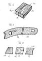
- Fig. 6 shows a perspective view of a producible by the process according to the invention component, for example, a part of a front side of a kitchen forming lid.
- the component 90 has an upper side 92 and two side surfaces 94 and 96.
- the wood grain patterns on top 92 and side surfaces 94 and 96 are formed to conform to a real wood board cut out of a tree, with the cut directions parallel to side surface 96 and perpendicular to side surface 94 and top surface 92, respectively lie.
- the woodgrain pattern of the side surface 96 thus corresponds to a frontal wood.
- the grains of the side surfaces 94 and 96 close to the grain of the top 92 steadily, ie the grain lines are merging in the edges into each other.
- step 42 By the method according to the invention can be represented by corresponding records alone in the ink jet printing step 42 a wide variety of woods with different nuances in an indistinguishable from real wood appearance. This is especially successful if step 42 ( Fig. 2 ) is performed on a natural wood veneered body.
- the wood veneer gives the printed body a real wood appearance, with a natural grain of the veneer is covered by the printed grain so that it no longer appears.
- embossing, grinding and priming of the base body is prepared so that the applied pattern of a real wood grain is indistinguishable.
- the protective layer applied in step 44 for example transparent two-component lacquer with the respective requirement of gloss, makes the component produced according to the invention hard-wearing and wear-resistant.
- the patterns may be taken directly from a master of the base in solid wood and used as datasets to control the inkjet printhead similar to printing a color original.
- patterns may be computationally generated according to respective templates, so that a variety of patterns that are not limited to woodgrain patterns can be generated.
- the data calculation takes place in such a way that the pattern contours (and colors) merge into one another according to the respective cuts at the edges (which can also be formed with radii of curvature).
- Data stores may store a sample of a variety of woods or other geometric or spatial patterns, each read out according to the desired size and used for printing.
- the color or coloration of the veneer may affect the appearance of the finished base.
- White bleached veneers lead to a clearer color embossing of the finished pattern.
- Tinted veneers result in less pronounced, more homogeneous dyeings of the finished pattern, if one does not work with a high degree of coverage.
- Fig. 7 shows an example of two vehicle interior deerboard components 98 and 100 printed according to the invention with woodgrain patterns.
- the woodgrain patterns in the area in which the components 98 and 100 adjoin one another are matched to one another in such a way that that they correspond or merge. In this way, the impression is created that the two components 98 and 100 are made of a single piece of natural wood, which increases the quality of the appearance.
- Fig. 8 shows how stored by appropriate data processing patterns can be adapted to the geometry of the component to be manufactured.
- Fig. 8b shows a basic pattern of a rectangular component 102.
- Fig. 8a shows the pattern corresponding to the component 102 on a component 104, which tapers in accordance with the figure upwards. The pattern lines are compressed according to the taper of the component.
- Fig. 8c shows a component 106, which is constricted in its central region.
- the pattern is constricted according to the constriction of the component. It is understood that the variations of the pattern present on the component 102 corresponding to the component 104 and 106 generally no longer correspond to a natural solid wood pattern; however, the effects produced by the compression of the patterns produce an aesthetically pleasing appearance of the components.
- the invention can be modified in many different ways. Various method steps can be combined with one another in a wide variety of ways, so that, with the exception of the inkjet printing method, only individual steps of the sequences according to FIG Fig. 2 must be present.
- left branch can, for example, if the starting body is a solid wood body made of simple wood, the veneer level, the boundary level and the embossing stage are missing.
- a veneer stage and a grinding stage can be provided in the right branch.
- the embossing steps may be missing in both branches etc.
- inks for example, pigment inks are used, as they are used in plotters.
- primers or adhesion promoters are used for the priming of plastic surfaces.
- wood priming liquids are used for the wood primer.
- protective layer are customary transparent coatings, which harden to a high-strength layer. When used as a parquet element conventional parquet seals can be used.
- Cost-effective blanks can be used to produce components of the highest quality that meet the highest quality requirements.
- storage only a stock with a small variety (sizes, material of the raw body) is required.
- the customer-relevant variety in terms of wood species, surface design and so on is achieved shortly before delivery due to the order entry by inkjet printing.
Abstract
Description
Die Erfindung betrifft ein Verfahren zum Herstellen eines Bauteils mit einer bedruckten Echtholzoberfläche vorbestimmten Aussehens.The invention relates to a method for producing a component with a printed real wood surface of predetermined appearance.
Aus der
Aus der
In der
Ein Problem, das sich bei mit einer Oberfläche vorbestimmten Aussehens herzustellenden Bauteilen stellt, liegt darin, dass beispielsweise plattenförmige Bauteile, die mit einer Holzmaserung versehen werden, nicht das Aussehen von Echtholzplatten haben, da ihre Seitenflächen ebenso wie die Oberfläche zwar mit einer Holzmaserung bedruckt werden, die Holzmaserungen der Oberseite und der sichtbaren Seitenflächen jedoch nicht zusammenpassen, so dass der Betrachter von vornherein sieht, dass es sich um keine Massivholzplatte, sondern um eine furnierte Platte handelt.A problem which arises in components to be produced with a surface of predetermined appearance is that, for example, plate-shaped components provided with a wood grain do not have the appearance of real wood panels, since their side surfaces, like the surface, are indeed printed with a wood grain However, the wood grains of the top and the visible side surfaces do not match, leaving the viewer From the outset sees that it is not a solid wood panel, but a veneered panel.
Der Erfindung liegt die Aufgabe zugrunde, ein Verfahren zum Herstellen eines Bauteils mit einer bedruckten Echtholzoberfläche anzugeben, mit dem kostengünstig Bauteile mit hochwertig aussehenden Oberflächen herstellbar sind.The invention has for its object to provide a method for producing a component with a printed real wood surface, with the cost components with high-quality-looking surfaces can be produced.
Die Ansprüche 1 und 3 sind auf Lösungen dieser Aufgabe gerichtet.
Die Unteransprüche kennzeichnen vorteilhafte Weiterbildungen der erfmdungsgemäßen Verfahren.The subclaims characterize advantageous developments of the inventive method.
Die Erfindung wird im Folgenden anhand schematischer Zeichnungen beispielsweise und mit weiteren Einzelheiten erläutert.The invention is explained below with reference to schematic drawings, for example, and with further details.
- Fig. 1Fig. 1
- eine Prinzipdarstellung des Aufbaus einer Vorrichtung zur Durchführung einer Tintenstrahlbedruckung,a schematic diagram of the structure of an apparatus for performing an ink jet printing,
- Fig. 2Fig. 2
- ein Flussdiagramm zur Erläuterung der Herstellung eines nach dem erfindungsgemäßen Verfahren hergestellten Bauteils,a flowchart for explaining the preparation of a component produced by the method according to the invention,
- Fig. 3Fig. 3
- Teilschnitte von Bauteilen mit unterschiedlichen Rändern,Partial sections of components with different edges,
- Fig. 4Fig. 4
- perspektivische Ansichten unterschiedlich geprägter Grundkörper,perspective views of differently embossed basic body,
- Fig. 5Fig. 5
- Skizzen zur Erläuterung der Tintenstrahlbedruckung,Sketches explaining the inkjet printing,
- Fig. 6Fig. 6
- ein erfindungsgemäß hergestelltes Bauteil,a component produced according to the invention,
- Fig. 7Fig. 7
- ein weiteres Beispiel für erfindungsgemäß hergestellte Bauteile, unda further example of components produced according to the invention, and
- Fig. 8Fig. 8
- weitere erfindungsgemäß hergestellte Bauteile.further components produced according to the invention.
Gemäß
Die Position des Grundkörpers 2 wird mittels einer Sensoreinrichtung 16 erfasst.The position of the
Zur Steuerung der Antriebe und des Tintenstrahldruckkopfes 8 ist ein elektronisches Steuergerät 18 vorgesehen, das einen Mikroprozessor 20 mit zugehörigen Programm- und Datenspeichern 22, 24 enthält. Eingänge 26 des Steuergerätes 18 sind mit der Sensoreinrichtung 16 verbunden; Ausgänge 28 sind mit den verschiedenen Antriebseinrichtungen und dem Tintenstrahldruckkopf verbunden.To control the drives and the
Insgesamt ist es mit der beschriebenen Einrichtung möglich, den Tintenstrahldruckkopf 8 relativ zu dem Grundkörper 2 derart zu bewegen, dass der Tintenstrahldruckkopf 8 die gesamte Oberfläche des Grundkörpers 2 einschließlich dessen Seitenflächen unter Beibehaltung eines vorbestimmten Abstandes zwischen dem Tintenstrahldruckkopf 8 und der Oberfläche des Grundkörpers 2 und einem vorbestimmten Winkel zwischen dem vom Tintenstrahldruckkopf 8 abgespritzten Tintenstrahl und der Oberfläche des Grundkörpers 2 überstreicht. Wie ersichtlich, können auch Vorsprünge, Einbuchtungen oder sonstige Unebenheiten des Grundkörpers 2 auf diese Weise überstrichen werden.Overall, it is possible with the described device to move the ink
Für die Antriebs- und Transporteinrichtungen, mit denen die Relativbewegungen zwischen Tintenstrahldruckkopf 8 und Oberfläche des Grundkörpers 2 erzielt werden, bestehen unterschiedlichste Möglichkeiten. Der Grundkörper 2 kann ortsfest sein und der Tintenstrahldruckkopf 8 kann bewegt und verschwenkt werden. Umgekehrt kann auch der Tintenstrahldruckkopf 8 ortsfest sein und der Grundkörper 2 verschwenkt und linear bewegt werden.For the drive and transport devices with which the relative movements between the
In dem Steuergerät 18 ist ein auf den Grundkörper 2 aufzubringendes Muster derart gespeichert, dass jedem Oberflächenpunkt des Grundkörpers 2 ein Farbpixel nach Art der Farbe und Menge zugeordnet ist. Die Rasterfeinheit (Pixelgröße) richtet sich nach den Erfordernissen und technischen Möglichkeiten. Für eine einwandfreie Zuordnung des augenblicklich vor dem Tintenstrahlkopf 8 befindlichen Oberflächenelements kann die Geometrie des Grundkörpers gesamthaft in dem Steuergerät 18 gespeichert werden, so dass mittels der Sensoreinrichtung 16 lediglich eine Referenzstellung des Grundkörpers 2 erfasst werden muss. In einer weitergebildeten Ausführungsform der Sensoreinrichtung können am Druckkopf 8 selbst Sensoren, beispielsweise Ultraschallsensoren, angebracht sein, die den Abstand zwischen Tintenstrahldruckkopf 8 und der Oberfläche des Grundkörpers 2 und deren Relativausrichtung erfassen. Eine beispielhafte Sensoreinrichtung ist in der eingangs genannten
Anhand der
Der in
Im Schritt 30 wird beispielsweise aus einer Pressspanplatte ein Rohkörper zugeschnitten, dessen Abmessungen etwa denen des herzustellenden Bauteils entsprechen. Der Rohkörper kann aus jedwelchem geeigneten Material bestehen, beispielsweise auch aus einer gewichtsgünstigen Honey-comb-Struktur, die aus Kunststoff oder Faserverbundwerkstoff besteht. Im dargestellten Beispiel wird angenommen, dass der Rohkörper plattenförmige Gestalt hat. Im Schritt 32 wird zumindest auf die Oberseite des Rohkörpers ein Echtholzfurnier in an sich bekannter Weise aufgebracht. Das Echtholzfurnier kann aus preiswertem Holz, beispielsweise Esche, Birke, Buche, Ulme oder anderen kostengünstigen Qualitätshölzern bestehen.In
Im Schritt 34 werden die Seitenflächen des plattenförmigen, mit einem Furnier versehenen Rohkörpers, der beispielsweise einen Zentimeter dick ist, mit Randelementen versehen, die ebenfalls Holzfurniere sein können, aber auch durch Kunststoffumleimer usw. gebildet sein können. Weiter wird im Schritt 34 der Übergang zwischen den Randelementen und den anderen Flächen des Körpers mechanisch sauber bearbeitet, so dass die Abmessungen des nun einen Grundkörper bildenden Rohkörpers nach dem Schritt 34 dem des herzustellenden fertigen Bauteils entsprechen.In
Im Schritt 36 wird die Oberfläche des Rohkörpers je nach Bedarf, beispielsweise durch Kalandrieren, mit einer Prägung versehen.In
Im Schritt 38 wird die Oberfläche mit einer auf die nachfolgenden Schritte abgestimmten Rauhigkeit geschliffen.In
Im Schritt 40 wird die beschliffene Oberfläche mit einer Grundierungsschicht versehen. Das Grundieren kann in einer ähnlich der
Der Grundierungsschritt 40 dient in erster Linie dazu, dass die in dem nachfolgenden Tintenstrahlbedruckungsschritt 42 aufgebrachte Tinte auf der Oberfläche gut haftet und in vorbestimmter Weise verläuft. In dem Tintenstrahldruckverfahrensschritt wird auf die Oberfläche ein Muster aufgebracht, das im Wesentlichen durch drei Datensätze bestimmt ist, nämlich
- die Geometrie des Musters, die das Musterornament beispielsweise in schwarz-weiß als Linienmuster mit dem Schwärzungsgrad der einzelnen Oberflächenelemente festlegt,
- die Farbe des Musters, die die Farbe der einzelnen Oberflächenelemente festlegt, und
- der Deckungsgrad des Musters, der die Farbmenge mit der Maßgabe festlegt, inwieweit die Oberfläche des noch nicht bedruckten Grundkörpers durch die Druckschicht hindurchscheinen soll. Es versteht sich, dass der Deckungsgrad sowohl durch die Deckfähigkeit der Tinte als auch durch die aufgebrachte Tintenmenge bestimmt wird.
- the geometry of the pattern, which defines the pattern ornament, for example, in black and white as a line pattern with the degree of blackening of the individual surface elements,
- the color of the pattern, which determines the color of the individual surface elements, and
- the degree of coverage of the pattern, which determines the amount of ink with the proviso, to what extent the surface of the not yet printed body is to shine through the print layer. It is understood that the degree of coverage is determined by both the opacity of the ink and the amount of ink applied.
An den Schritt 42 schließt sich ein Schritt 44 an, in dem der tintenstrahlbedruckte Grundkörper mit einer Schutzschicht versehen wird, die durch Spritzen, Rollen, Tauchen usw. aufgebracht werden kann.The
Wenn von einem Rohkörper beziehungsweise einer Platte mit Kunststoffoberfläche, beispielsweise einer melaminbeschichteten Platte ausgegangen wird, die flächig nicht furniert werden soll, wird in einem Schritt 50 eine Rohplatte ausgeschnitten, die im Schritt 54 mit einer Umrandung, beispielsweise einem Umleimer, versehen wird. Zusätzlich wird im Schritt 54 der Übergang zwischen dem Umleimer und der Plattenoberfläche mechanisch sauber bearbeitet, so dass die Gestalt des hergestellten Grundkörpers dem eines herzustellenden Bauteils entspricht.If it is assumed that a green body or a plate with a plastic surface, for example a melamine-coated plate which is not intended to be veneered surface, in a step 50, a raw plate is cut, which is provided in
Im Schritt 56 wird der Grundkörper im Bedarfsfall mit einer Prägung versehen.In
Auf den Schritt 56 folgt ein Grundierschritt 60, in dem die Oberfläche des Grundkörpers derart grundiert wird, dass die im nachfolgenden Tintenstrahlbedruckungsschritt 42 aufgebrachte Tinte einwandfrei auf der Oberfläche haftet. An den Schritt 42 schließt sich zur Fertigbearbeitung der Schutzschritt 44 an.
Im Folgenden werden einige Aspekte der beschriebenen Schritte erläutert.Here are some aspects of the steps described.
Nach Aufbringen der Randelemente wird der Übergangsbereich zwischen dem Randelement und dem Rohkörper jeweils sauber mechanisch bearbeitet, so dass der hergestellte Grundkörper keine Unsauberkeiten im Übergang zu dem bzw. zu den Randelementen hat. Bei geeigneter Beschaffenheit des Rohkörpers kann dessen Rand auch ohne jedwelches gesondert aufgebrachtes Randelement lediglich durch mechanische Bearbeitung geformt werden.After applying the edge elements, the transition region between the edge element and the green body is in each case treated cleanly mechanically so that the base body produced has no imperfections in the transition to or to the edge elements. With a suitable condition of the green body, its edge can also be shaped without any separately applied edge element merely by mechanical processing.
Gemäß
Der Schleifschritt 38 beeinflusst das Aussehen der nachfolgenden Tintenstrahlbedruckung ebenfalls stark. Ein grober Schliff führt zu einem Verlaufen der Farbpunkte. Mit zunehmend feinerem Schliff lassen sich zunehmend scharf gezeichnete Musterungen aufbringen.The grinding
Die im Schritt 40 bzw. 60 aufgebrachte Grundierung dient nicht nur einer guten Haftung der aufgedruckten Tinte. Mit der Grundierung kann auch das Saugverhalten der Oberfläche beeinflusst werden, was zusätzlich zur Menge und zum Farbstoffgehalt der Tinte Einfluss darauf hat, ob das durch Tintenstrahlbedruckung aufgebrachte Muster voll deckend oder lediglich lasierend ist.The primer applied in
Gemäß
Wenn der Tintenstrahldruckkopf 8 gemäß
Nach dem erfindungsgemäßen Verfahren lassen sich allein durch entsprechende Datensätze im Tintenstrahldruckschritt 42 unterschiedlichste Holzarten mit unterschiedlichsten Nuancierungen in einem von Echtholz nicht unterscheidbaren Aussehen darstellen. Besonders gut gelingt dies, wenn der Schritt 42 (
Für die Datengewinnung der in dem Steuergerät gespeicherten Muster gibt es verschiedene Möglichkeiten. Beispielsweise können die Muster unmittelbar von einer Vorlage des Grundkörpers in Massivholz abgenommen und als Datensätze zur Steuerung des Tintenstrahldruckkopfes ähnlich wie beim Ausdrucken einer Farbvorlage verwendet werden. Alternativ können Muster nach entsprechenden Vorlagen rechnerisch generiert werden, so dass unterschiedlichste Muster, die nicht auf Holzmaserungsmuster begrenzt sind, erzeugt werden können. Dabei erfolgt die Datenberechnung jeweils derart, dass die Musterkonturen (und Farben) entsprechend den jeweiligen Schnitten an den Kanten (die auch mit Krümmungsradien ausgebildet sein können), ineinander übergehen. In Datenspeichern kann ein Mustervorrat unterschiedlichster Hölzer oder anderweitiger geometrischer oder räumlicher Muster gespeichert sein, die jeweils entsprechend der gewünschten Größe ausgelesen und zum Drucken benutzt werden.There are various possibilities for the data acquisition of the patterns stored in the control unit. For example, the patterns may be taken directly from a master of the base in solid wood and used as datasets to control the inkjet printhead similar to printing a color original. Alternatively, patterns may be computationally generated according to respective templates, so that a variety of patterns that are not limited to woodgrain patterns can be generated. In each case, the data calculation takes place in such a way that the pattern contours (and colors) merge into one another according to the respective cuts at the edges (which can also be formed with radii of curvature). Data stores may store a sample of a variety of woods or other geometric or spatial patterns, each read out according to the desired size and used for printing.
Wenn mit mit Holzfurnieren versehenen Grundkörpern gearbeitet wird, kann durch die Farbe oder Färbung des Furniers das Aussehen des fertigen Grundkörpers beeinflusst werden. Weiß gebleichte Furniere fuhren zu einer klareren Farbprägung des fertigen Musters. Getönte Furniere ergeben weniger ausgeprägte, homogenere Färbungen des fertigen Musters, wenn nicht mit hohem Deckungsgrad gearbeitet wird.When working with wood veneered bases, the color or coloration of the veneer may affect the appearance of the finished base. White bleached veneers lead to a clearer color embossing of the finished pattern. Tinted veneers result in less pronounced, more homogeneous dyeings of the finished pattern, if one does not work with a high degree of coverage.
Mit dem beschriebenen Verfahren können unterschiedlichste Bauteile hergestellt werden, die von dem einfachen, nur auf einer Oberflächenseite bedruckten Parkettelement (das entsprechend verschleißfest beschichtet ist), bis zu komplizierter geformten dreidimensionalen Bauteilen reichen, beispielsweise Innenraumdekorteilen in Kraftfahrzeugen.With the method described, a wide variety of components can be produced, ranging from the simple parquet element printed on only one surface side (which is correspondingly wear-resistant coated) to more complexly shaped three-dimensional components, for example interior trim parts in motor vehicles.
Die Erfindung kann in unterschiedlichster Weise abgeändert werden. Es können verschiedene Verfahrensschritte in unterschiedlichster Weise miteinander kombiniert werden, so dass, mit Ausnahme des Tintenstrahldruckverfahrens, nur einzelne Schritte der Abläufe gemäß
Die Feinbearbeitung der Randelemente derart, dass beim Bedrucken der Übergang zwischen dem Randelement und dem Rohkörper nicht mehr sichtbar ist, kann innerhalb des Schleifschrittes 38 folgen usw.The fine machining of the edge elements such that when printing the transition between the edge element and the green body is no longer visible, can follow within the grinding
Als Tinten werden beispielsweise Pigmenttinten verwendet, wie sie auch in Plottern eingesetzt werden. Für die Grundierung von Kunststoffoberflächen werden handelsübliche Primer bzw. Haftvermittler eingesetzt. Für die Holzgrundierung werden ggfs. übliche Holzgrundierungsflüssigkeiten eingesetzt. Für die Schutzschicht eignen sich übliche transparente Lacke, die zu einer hochfesten Schicht härten. Bei Verwendung als Parkettelement können übliche Parkettversiegelungen verwendet werden.As inks, for example, pigment inks are used, as they are used in plotters. Commercially available primers or adhesion promoters are used for the priming of plastic surfaces. If necessary, the usual wood priming liquids are used for the wood primer. For the protective layer are customary transparent coatings, which harden to a high-strength layer. When used as a parquet element conventional parquet seals can be used.
Der Anmelder behält sich vor, einzelne Merkmale und Ansprüche auch für sich und nicht in Kombination mit denen anderer Ansprüche zu beanspruchen.The applicant reserves the right to claim individual features and claims on their own behalf and not in combination with those of other claims.
Mit der Erfindung werden zahlreiche Vorteile erzielt, die nicht nur das Aussehen der hergestellten Bauteile, sondern vor allem deren Kosten betreffen. Aus kostengünstigen Rohteilen können Bauteile mit höchstwertigstem Aussehen hergestellt werden, die höchste Qualitätsanforderungen erfüllen. Bezüglich der Lagerhaltung ist lediglich ein Vorrat mit geringer Vielfalt (Größen, Material des Rohkörpers) erforderlich. Die kundenrelevante Vielfalt hinsichtlich Holzart, Oberflächendesign und so weiter wird erst kurz vor der Auslieferung aufgrund des Bestelleingangs durch Tintenstrahlbedruckung erzielt.With the invention numerous advantages are achieved, which affect not only the appearance of the manufactured components, but especially their cost. Cost-effective blanks can be used to produce components of the highest quality that meet the highest quality requirements. With regard to storage, only a stock with a small variety (sizes, material of the raw body) is required. The customer-relevant variety in terms of wood species, surface design and so on is achieved shortly before delivery due to the order entry by inkjet printing.
- 22
- Grundkörperbody
- 44
- Transportplattetransport plate
- 66
- TintenstrahldruckeinrichtungInkjet printing apparatus
- 88th
- TintenstrahldruckkopfInkjet printhead
- 1010
- Armpoor
- 1212
- Konsoleconsole
- 1414
- Zylindercylinder
- 1616
- Sensoreinrichtungsensor device
- 1818
- Steuergerätcontrol unit
- 2020
- Mikroprozessormicroprocessor
- 2222
- SpeicherStorage
- 2424
- SpeicherStorage
- 2626
- Eingängeinputs
- 2828
- Ausgängeoutputs
- 7272
- RandelementBoundary element
- 7474
- RandelementBoundary element
- 7676
- RandelementBoundary element
- 7878
- Grundkörperbody
- 8080
- Tintenstrahlinkjet
- 9090
- Bauteilcomponent
- 9292
- Oberseitetop
- 9494
- Seitenflächeside surface
- 9696
- Seitenflächeside surface
- 9898
- Bauteilcomponent
- 100100
- Bauteilcomponent
- 102102
- Bauteilcomponent
- 104104
- Bauteilcomponent
- 106106
- Bauteilcomponent
Claims (11)
Applications Claiming Priority (2)
| Application Number | Priority Date | Filing Date | Title |
|---|---|---|---|
| DE10323412A DE10323412B4 (en) | 2003-05-23 | 2003-05-23 | Method and device for producing a component having a surface of predetermined appearance |
| EP04012101A EP1479524B1 (en) | 2003-05-23 | 2004-05-21 | Method and device for the production of a component with a pre-determined surface appearance |
Related Parent Applications (1)
| Application Number | Title | Priority Date | Filing Date |
|---|---|---|---|
| EP04012101A Division EP1479524B1 (en) | 2003-05-23 | 2004-05-21 | Method and device for the production of a component with a pre-determined surface appearance |
Publications (1)
| Publication Number | Publication Date |
|---|---|
| EP2080624A1 true EP2080624A1 (en) | 2009-07-22 |
Family
ID=33039300
Family Applications (3)
| Application Number | Title | Priority Date | Filing Date |
|---|---|---|---|
| EP04012101A Active EP1479524B1 (en) | 2003-05-23 | 2004-05-21 | Method and device for the production of a component with a pre-determined surface appearance |
| EP10180081A Active EP2292437B1 (en) | 2003-05-23 | 2004-05-21 | Method and device for the production of a component with a pre-determined surface appearance |
| EP09001678A Withdrawn EP2080624A1 (en) | 2003-05-23 | 2004-05-21 | Method for producing a component with a printed real wood surface of a particular appearance |
Family Applications Before (2)
| Application Number | Title | Priority Date | Filing Date |
|---|---|---|---|
| EP04012101A Active EP1479524B1 (en) | 2003-05-23 | 2004-05-21 | Method and device for the production of a component with a pre-determined surface appearance |
| EP10180081A Active EP2292437B1 (en) | 2003-05-23 | 2004-05-21 | Method and device for the production of a component with a pre-determined surface appearance |
Country Status (7)
| Country | Link |
|---|---|
| EP (3) | EP1479524B1 (en) |
| AT (1) | ATE491579T1 (en) |
| DE (2) | DE10323412B4 (en) |
| ES (2) | ES2357892T3 (en) |
| PL (2) | PL1479524T3 (en) |
| PT (2) | PT1479524E (en) |
| SI (2) | SI2292437T1 (en) |
Cited By (2)
| Publication number | Priority date | Publication date | Assignee | Title |
|---|---|---|---|---|
| CN104442181A (en) * | 2014-10-30 | 2015-03-25 | 佛山市天元汇邦装饰材料有限公司 | High-imitation wood grain paper |
| EP3216621A1 (en) * | 2016-03-10 | 2017-09-13 | VD Werkstätten GmbH & Co. KG | Method for manufacturing relief panels having an end-wood pattern |
Families Citing this family (39)
| Publication number | Priority date | Publication date | Assignee | Title |
|---|---|---|---|---|
| ITTV20050035A1 (en) * | 2005-03-04 | 2006-09-05 | Roberto Brao | Method for making a decorated piece of furniture. |
| DE102005036541B9 (en) * | 2005-08-03 | 2010-02-11 | Bauer, Jörg R. | Process for producing a paper surface, paper web and article coated therewith in particular by means of an inkjet printing process |
| DE102005059540A1 (en) * | 2005-08-19 | 2007-06-14 | Bauer, Jörg R. | Reliably fastened to each other, flat components, and component |
| DE102005060753A1 (en) * | 2005-12-16 | 2007-06-21 | Kronotec Ag | Floor panel`s profiled section printing method, involves applying inkjet-printing ink with binding material on profiled section to be printed in operating condition by using fixed print heads that are arranged one after another |
| EP1837189B1 (en) | 2006-03-08 | 2016-10-12 | HOMAG GmbH | Device for refining of workpieces |
| ES2601398T3 (en) | 2006-03-08 | 2017-02-15 | Homag Holzbearbeitungssysteme Ag | Procedure and device for printing work pieces in plate form |
| DE102006014644A1 (en) * | 2006-03-30 | 2007-10-04 | Robert Bürkle GmbH | Device for contour-accurate printing of decorative images on flat workpieces |
| ITMI20061227A1 (en) | 2006-06-26 | 2007-12-27 | Dante Frati | PROCEDURE FOR PRINTING SURFACES OF FLAT BASE ELEMENTS |
| DE502006005293D1 (en) | 2006-08-25 | 2009-12-17 | Homag Holzbearbeitungssysteme | Device for patterning workpieces |
| DE102006052293C5 (en) | 2006-11-03 | 2011-02-03 | Kronotec Ag | Wood-based panel with real wood veneer and process for its production |
| US7914098B2 (en) | 2006-11-07 | 2011-03-29 | Homag Holzbearbeitungssysteme Ag | Device for patterning workpieces |
| PL1974928T3 (en) | 2007-03-27 | 2010-04-30 | Homag Holzbearbeitungssysteme Ag | Method for printing on a three-dimensional container |
| DE102007017503B3 (en) | 2007-04-13 | 2008-11-06 | Bauer, Jörg R. | Method for producing a component with a printed real wood surface and component produced by the method |
| DE102007021767A1 (en) | 2007-05-09 | 2008-11-13 | Bauer, Jörg R. | Method and device for printing a component with two mutually inclined surface areas by means of a digital printing method |
| DE102007043202A1 (en) * | 2007-09-11 | 2009-03-26 | Guido Schulte | Floor/wall/ceiling panel, has carrier plate made of fiber material, upper-sided solid wood layer constituted of stamped surface structure, and intermediate layer provided between carrier plate and wood layer |
| DE202007014991U1 (en) | 2007-10-27 | 2009-03-12 | Rehau Ag + Co | Edging strip for furniture |
| ITMI20080572A1 (en) * | 2008-04-02 | 2009-10-03 | Colograf S R L | DECORATED WOODEN CONTAINER. |
| DE102008028000A1 (en) * | 2008-06-12 | 2009-12-17 | Kaindl Flooring Gmbh | Method of printing a trim panel |
| DE102008063837A1 (en) | 2008-12-19 | 2010-06-24 | Mankiewicz Gebr. & Co. Gmbh & Co Kg | Coating and its production by inkjet printing process |
| DE102009007114C5 (en) | 2009-02-02 | 2014-03-13 | Guido Schulte | Method for producing a surface of a component, its use and surface of a component |
| DE102010054578A1 (en) * | 2010-12-15 | 2012-06-21 | Erfurt & Sohn Kg | Sheets, particularly strips of wall papers, are made of paper, metal or plastic, whose front surface is printed and adjacent and adjoining front sides of longitudinal edges form image or art design |
| EP2730418B1 (en) | 2012-11-12 | 2015-06-03 | Lite-on Mobile Oyj | 3D dispensing apparatus and method |
| DE102013214980A1 (en) * | 2013-07-31 | 2015-02-05 | Krones Ag | Printing machine with printhead control |
| DE102013216113A1 (en) | 2013-08-14 | 2015-03-05 | Homag Holzbearbeitungssysteme Gmbh | coating unit |
| ES2541811B1 (en) * | 2014-01-24 | 2016-04-21 | Manprocar Vigo, S.L. | Method of manufacturing wooden elements for lining of vehicle steering wheels |
| DE102014012395A1 (en) | 2014-08-21 | 2016-02-25 | Heidelberger Druckmaschinen Ag | Method and apparatus for printing a curved surface of an object with an ink jet head |
| CN108136814A (en) * | 2015-10-19 | 2018-06-08 | 得嘉公司 | Manufacture embossing and the method for digital print substrate |
| US20190023045A1 (en) * | 2016-02-12 | 2019-01-24 | Arnaldo URRUTIA BAZÁN | System, method and computer program for edging parts by printing |
| JP6906279B2 (en) * | 2016-07-12 | 2021-07-21 | アイカ工業株式会社 | Cosmetic material |
| DE102016015027A1 (en) | 2016-12-16 | 2018-01-11 | Daimler Ag | Method for smoothing a surface |
| DE102017002890A1 (en) | 2017-03-25 | 2018-09-27 | Röhr GmbH | A method of processing a board having a wood surface, and a board made by the method |
| AT520096B1 (en) * | 2017-08-14 | 2019-01-15 | Ifn Holding Ag | Method for producing a window or door profile |
| CN109016918A (en) * | 2018-07-11 | 2018-12-18 | 四川鼎际恒荣金属材料有限公司 | A kind of production technology of metal veneer wood grain glue thermal transfer |
| AT521998B1 (en) * | 2018-11-23 | 2021-12-15 | Karl Pedross Ag | Process for printing elongated profile strips and profile strips |
| EP3798813A1 (en) * | 2019-09-24 | 2021-03-31 | Jesús Francisco Barberan Latorre | Method for decorating a substrate and substrate thus decorated |
| JP7472680B2 (en) * | 2020-06-29 | 2024-04-23 | セイコーエプソン株式会社 | Three-dimensional object printing device and three-dimensional object printing method |
| CN112976856A (en) * | 2021-02-03 | 2021-06-18 | 成都雅印电子科技有限公司 | Digital graph-based integrated jet printing method |
| DE102021133045A1 (en) * | 2021-12-14 | 2023-06-15 | Homag Gmbh | Method for creating a printed decoration, method for printing a workpiece and system |
| DE102022108850A1 (en) * | 2022-04-12 | 2023-10-12 | Homag Gmbh | Device for finishing a workpiece surface with a pivoting print head |
Citations (6)
| Publication number | Priority date | Publication date | Assignee | Title |
|---|---|---|---|---|
| DE19532724A1 (en) | 1995-09-05 | 1997-03-06 | Tampoprint Gmbh | Multi-color printing device |
| EP0931649A2 (en) | 1998-01-27 | 1999-07-28 | Eastman Kodak Company | Apparatus and method for making a contoured surface having complex topology |
| EP1145859A2 (en) * | 2000-04-11 | 2001-10-17 | Comital S.p.A. | Method for the realization of printed polychrome decoration on metal artifacts and related apparatus |
| WO2002000449A1 (en) * | 2000-06-26 | 2002-01-03 | Bauer Joerg R | Method, system and device for the production of components with a pre-determined surface appearance, in particular for front panels of kitchen units |
| US20030043246A1 (en) * | 2001-08-30 | 2003-03-06 | L&P Property Management Company | Method and apparatus for ink jet printing on rigid panels |
| WO2003084760A1 (en) * | 2002-04-03 | 2003-10-16 | Masonite Corporation | Method and apparatus for creating an image on an article, and printed article |
Family Cites Families (5)
| Publication number | Priority date | Publication date | Assignee | Title |
|---|---|---|---|---|
| JPH0679885A (en) * | 1992-06-24 | 1994-03-22 | Sony Corp | Printing method, printer, printing head, printed article container and printing method of cassette |
| US5429682A (en) * | 1993-08-19 | 1995-07-04 | Advanced Robotics Technologies | Automated three-dimensional precision coatings application apparatus |
| US6360656B2 (en) * | 2000-02-28 | 2002-03-26 | Minolta Co., Ltd. | Apparatus for and method of printing on three-dimensional object |
| US6460958B2 (en) * | 2000-02-29 | 2002-10-08 | Minolta Co., Ltd. | Three-dimensional object printing apparatus and method |
| US20030020767A1 (en) * | 2001-07-24 | 2003-01-30 | Saksa Thomas A. | Grain forming ink jet printer for printing a grain on a workpiece and method of assembling the printer |
-
2003
- 2003-05-23 DE DE10323412A patent/DE10323412B4/en not_active Expired - Fee Related
-
2004
- 2004-05-21 ES ES04012101T patent/ES2357892T3/en active Active
- 2004-05-21 PT PT04012101T patent/PT1479524E/en unknown
- 2004-05-21 PL PL04012101T patent/PL1479524T3/en unknown
- 2004-05-21 SI SI200432040T patent/SI2292437T1/en unknown
- 2004-05-21 EP EP04012101A patent/EP1479524B1/en active Active
- 2004-05-21 EP EP10180081A patent/EP2292437B1/en active Active
- 2004-05-21 AT AT04012101T patent/ATE491579T1/en active
- 2004-05-21 DE DE502004011985T patent/DE502004011985D1/en active Active
- 2004-05-21 PL PL10180081T patent/PL2292437T3/en unknown
- 2004-05-21 PT PT101800811T patent/PT2292437E/en unknown
- 2004-05-21 SI SI200431622T patent/SI1479524T1/en unknown
- 2004-05-21 EP EP09001678A patent/EP2080624A1/en not_active Withdrawn
- 2004-05-21 ES ES10180081T patent/ES2411688T3/en active Active
Patent Citations (7)
| Publication number | Priority date | Publication date | Assignee | Title |
|---|---|---|---|---|
| DE19532724A1 (en) | 1995-09-05 | 1997-03-06 | Tampoprint Gmbh | Multi-color printing device |
| EP0931649A2 (en) | 1998-01-27 | 1999-07-28 | Eastman Kodak Company | Apparatus and method for making a contoured surface having complex topology |
| EP1145859A2 (en) * | 2000-04-11 | 2001-10-17 | Comital S.p.A. | Method for the realization of printed polychrome decoration on metal artifacts and related apparatus |
| WO2002000449A1 (en) * | 2000-06-26 | 2002-01-03 | Bauer Joerg R | Method, system and device for the production of components with a pre-determined surface appearance, in particular for front panels of kitchen units |
| DE10031030A1 (en) | 2000-06-26 | 2002-01-17 | Joerg R Bauer | Method and device for producing flat components with a predetermined surface appearance, in particular front panels of kitchen elements |
| US20030043246A1 (en) * | 2001-08-30 | 2003-03-06 | L&P Property Management Company | Method and apparatus for ink jet printing on rigid panels |
| WO2003084760A1 (en) * | 2002-04-03 | 2003-10-16 | Masonite Corporation | Method and apparatus for creating an image on an article, and printed article |
Cited By (2)
| Publication number | Priority date | Publication date | Assignee | Title |
|---|---|---|---|---|
| CN104442181A (en) * | 2014-10-30 | 2015-03-25 | 佛山市天元汇邦装饰材料有限公司 | High-imitation wood grain paper |
| EP3216621A1 (en) * | 2016-03-10 | 2017-09-13 | VD Werkstätten GmbH & Co. KG | Method for manufacturing relief panels having an end-wood pattern |
Also Published As
| Publication number | Publication date |
|---|---|
| PL2292437T3 (en) | 2013-08-30 |
| DE502004011985D1 (en) | 2011-01-27 |
| PT2292437E (en) | 2013-05-13 |
| EP2292437A1 (en) | 2011-03-09 |
| SI2292437T1 (en) | 2013-07-31 |
| SI1479524T1 (en) | 2011-04-29 |
| PL1479524T3 (en) | 2011-08-31 |
| EP2292437B1 (en) | 2013-03-06 |
| ES2357892T3 (en) | 2011-05-03 |
| DE10323412B4 (en) | 2007-07-05 |
| DE10323412A1 (en) | 2004-12-30 |
| ES2411688T3 (en) | 2013-07-08 |
| PT1479524E (en) | 2011-01-26 |
| EP1479524A1 (en) | 2004-11-24 |
| EP1479524B1 (en) | 2010-12-15 |
| ATE491579T1 (en) | 2011-01-15 |
Similar Documents
| Publication | Publication Date | Title |
|---|---|---|
| EP1479524B1 (en) | Method and device for the production of a component with a pre-determined surface appearance | |
| EP2133154B1 (en) | Method, device and system to manufacture components with pre-set surface appearances, especially the front plates for kitchen elements | |
| EP2218520B1 (en) | Method and device for producing a structured surface | |
| EP1990204B1 (en) | Process and device for coating a surface | |
| EP2593244B1 (en) | Method for producing a panel having a decorative finish and a three-dimensional structure | |
| EP2292435B1 (en) | Method for producing a component having a printed real wood surface and component produced according to the method | |
| EP2544902B1 (en) | Method and device for producing a board-shaped product having a surface comprising a decoration | |
| EP4215282A1 (en) | Method for producing a structure on a surface | |
| WO2008138530A2 (en) | Method for the production of a part having a relief surface, and such a part | |
| DE102018127648B3 (en) | Process for producing a molded part | |
| EP2301762B9 (en) | Method and a device for applying a structure to a composite wood board | |
| WO2004000524A1 (en) | Method for production of an object and object produced by said method | |
| DE102012103491A1 (en) | Method and device for producing a structured lacquer surface | |
| EP3656566B1 (en) | Method for printing longitudinal profile strips and profile strips | |
| EP2807039B1 (en) | Method for producing a plastic film having a coloured and embossed surface | |
| DE102008059719A1 (en) | Method for manufacturing decoration element, particularly for passenger cabin of vehicle, involves providing mold with profiled or structured surfaces made of nickel or nickeliferous material, and providing premolding made of wood | |
| DE20023641U1 (en) | Method to manufacture front panels for kitchen cupboards or other elements; involves printing parts with pre-determined pattern using method that may be programmed according to desired appearance | |
| AT520096B1 (en) | Method for producing a window or door profile | |
| DE102022116424A1 (en) | Pressing tool for pressing material panels in heating presses | |
| DE10003412A1 (en) | Method for surface finishing and refining three-dimensional wooden curtain rings, involves initially printing on one side of the ring and then on the other side in a two-step process | |
| DE102012008064A1 (en) | Method for engraving inhomogeneous decorative material e.g. trim portion for automobile, involves performing decorative material removal processing, while adjusting processing parameters as function of detected material regions |
Legal Events
| Date | Code | Title | Description |
|---|---|---|---|
| PUAI | Public reference made under article 153(3) epc to a published international application that has entered the european phase |
Free format text: ORIGINAL CODE: 0009012 |
|
| AC | Divisional application: reference to earlier application |
Ref document number: 1479524 Country of ref document: EP Kind code of ref document: P |
|
| AK | Designated contracting states |
Kind code of ref document: A1 Designated state(s): AT BE BG CH CY CZ DE DK EE ES FI FR GB GR HU IE IT LI LU MC NL PL PT RO SE SI SK TR |
|
| AX | Request for extension of the european patent |
Extension state: AL HR LT LV MK |
|
| RAP1 | Party data changed (applicant data changed or rights of an application transferred) |
Owner name: INTERGLARION LIMITED |
|
| RIN1 | Information on inventor provided before grant (corrected) |
Inventor name: INTERGLARION LIMITED |
|
| 17P | Request for examination filed |
Effective date: 20100127 |
|
| 17Q | First examination report despatched |
Effective date: 20100224 |
|
| AKX | Designation fees paid |
Designated state(s): AT BE BG CH CY CZ DE DK EE ES FI FR GB GR HU IE IT LI LU MC NL PL PT RO SE SI SK TR |
|
| RIN1 | Information on inventor provided before grant (corrected) |
Inventor name: DER ERFINDER HAT AUF SEINE NENNUNG VERZICHTET. |
|
| STAA | Information on the status of an ep patent application or granted ep patent |
Free format text: STATUS: THE APPLICATION IS DEEMED TO BE WITHDRAWN |
|
| 18D | Application deemed to be withdrawn |
Effective date: 20100907 |