EP2085443A1 - Process for producing resin porous membrane with adhesive layer, resin porous membrane with adhesive layer, and filter member - Google Patents
Process for producing resin porous membrane with adhesive layer, resin porous membrane with adhesive layer, and filter member Download PDFInfo
- Publication number
- EP2085443A1 EP2085443A1 EP07828618A EP07828618A EP2085443A1 EP 2085443 A1 EP2085443 A1 EP 2085443A1 EP 07828618 A EP07828618 A EP 07828618A EP 07828618 A EP07828618 A EP 07828618A EP 2085443 A1 EP2085443 A1 EP 2085443A1
- Authority
- EP
- European Patent Office
- Prior art keywords
- porous membrane
- adhesive layer
- resin
- adhesive
- resin composition
- Prior art date
- Legal status (The legal status is an assumption and is not a legal conclusion. Google has not performed a legal analysis and makes no representation as to the accuracy of the status listed.)
- Withdrawn
Links
- 239000012528 membrane Substances 0.000 title claims abstract description 266
- 229920005989 resin Polymers 0.000 title claims abstract description 140
- 239000011347 resin Substances 0.000 title claims abstract description 140
- 239000012790 adhesive layer Substances 0.000 title claims abstract description 119
- 238000000034 method Methods 0.000 title claims description 71
- 238000004519 manufacturing process Methods 0.000 claims abstract description 34
- 239000000853 adhesive Substances 0.000 claims description 116
- 230000001070 adhesive effect Effects 0.000 claims description 116
- 239000011342 resin composition Substances 0.000 claims description 100
- 239000003822 epoxy resin Substances 0.000 claims description 23
- 229920000647 polyepoxide Polymers 0.000 claims description 23
- 239000000758 substrate Substances 0.000 claims description 23
- 239000004593 Epoxy Substances 0.000 claims description 18
- 229920001343 polytetrafluoroethylene Polymers 0.000 claims description 17
- 239000004810 polytetrafluoroethylene Substances 0.000 claims description 17
- 238000010438 heat treatment Methods 0.000 claims description 12
- 239000000203 mixture Substances 0.000 claims description 11
- 238000012546 transfer Methods 0.000 claims description 10
- -1 polytetrafluoroethylene Polymers 0.000 claims description 9
- 229920000098 polyolefin Polymers 0.000 claims description 3
- 230000035699 permeability Effects 0.000 abstract description 16
- 238000011282 treatment Methods 0.000 description 47
- 238000011161 development Methods 0.000 description 17
- 239000010410 layer Substances 0.000 description 13
- 239000011521 glass Substances 0.000 description 9
- PXKLMJQFEQBVLD-UHFFFAOYSA-N bisphenol F Chemical compound C1=CC(O)=CC=C1CC1=CC=C(O)C=C1 PXKLMJQFEQBVLD-UHFFFAOYSA-N 0.000 description 8
- XLYOFNOQVPJJNP-UHFFFAOYSA-N water Substances O XLYOFNOQVPJJNP-UHFFFAOYSA-N 0.000 description 8
- ZWEHNKRNPOVVGH-UHFFFAOYSA-N 2-Butanone Chemical compound CCC(C)=O ZWEHNKRNPOVVGH-UHFFFAOYSA-N 0.000 description 6
- 239000002390 adhesive tape Substances 0.000 description 6
- IISBACLAFKSPIT-UHFFFAOYSA-N bisphenol A Chemical compound C=1C=C(O)C=CC=1C(C)(C)C1=CC=C(O)C=C1 IISBACLAFKSPIT-UHFFFAOYSA-N 0.000 description 6
- 230000001413 cellular effect Effects 0.000 description 5
- 239000000463 material Substances 0.000 description 5
- SECXISVLQFMRJM-UHFFFAOYSA-N N-Methylpyrrolidone Chemical compound CN1CCCC1=O SECXISVLQFMRJM-UHFFFAOYSA-N 0.000 description 4
- ZUOUZKKEUPVFJK-UHFFFAOYSA-N diphenyl Chemical compound C1=CC=CC=C1C1=CC=CC=C1 ZUOUZKKEUPVFJK-UHFFFAOYSA-N 0.000 description 4
- 239000000428 dust Substances 0.000 description 4
- 238000001878 scanning electron micrograph Methods 0.000 description 4
- 239000002904 solvent Substances 0.000 description 4
- 229920002799 BoPET Polymers 0.000 description 3
- 229920001577 copolymer Polymers 0.000 description 3
- 239000007788 liquid Substances 0.000 description 3
- 229920006287 phenoxy resin Polymers 0.000 description 3
- 239000013034 phenoxy resin Substances 0.000 description 3
- 125000001997 phenyl group Chemical group [H]C1=C([H])C([H])=C(*)C([H])=C1[H] 0.000 description 3
- 239000000126 substance Substances 0.000 description 3
- RYHBNJHYFVUHQT-UHFFFAOYSA-N 1,4-Dioxane Chemical compound C1COCCO1 RYHBNJHYFVUHQT-UHFFFAOYSA-N 0.000 description 2
- VXNZUUAINFGPBY-UHFFFAOYSA-N 1-Butene Chemical compound CCC=C VXNZUUAINFGPBY-UHFFFAOYSA-N 0.000 description 2
- 238000005033 Fourier transform infrared spectroscopy Methods 0.000 description 2
- 239000002253 acid Substances 0.000 description 2
- 235000010290 biphenyl Nutrition 0.000 description 2
- 239000004305 biphenyl Substances 0.000 description 2
- 239000003795 chemical substances by application Substances 0.000 description 2
- 238000000576 coating method Methods 0.000 description 2
- 238000007796 conventional method Methods 0.000 description 2
- GYZLOYUZLJXAJU-UHFFFAOYSA-N diglycidyl ether Chemical compound C1OC1COCC1CO1 GYZLOYUZLJXAJU-UHFFFAOYSA-N 0.000 description 2
- 229920000840 ethylene tetrafluoroethylene copolymer Polymers 0.000 description 2
- NIHNNTQXNPWCJQ-UHFFFAOYSA-N fluorene Chemical compound C1=CC=C2CC3=CC=CC=C3C2=C1 NIHNNTQXNPWCJQ-UHFFFAOYSA-N 0.000 description 2
- 239000013067 intermediate product Substances 0.000 description 2
- 238000005259 measurement Methods 0.000 description 2
- 230000003287 optical effect Effects 0.000 description 2
- 238000000206 photolithography Methods 0.000 description 2
- 229920003207 poly(ethylene-2,6-naphthalate) Polymers 0.000 description 2
- 239000011112 polyethylene naphthalate Substances 0.000 description 2
- 238000002360 preparation method Methods 0.000 description 2
- 238000007639 printing Methods 0.000 description 2
- 238000004080 punching Methods 0.000 description 2
- 230000003014 reinforcing effect Effects 0.000 description 2
- 239000005871 repellent Substances 0.000 description 2
- 229920001187 thermosetting polymer Polymers 0.000 description 2
- 239000002966 varnish Substances 0.000 description 2
- RNFJDJUURJAICM-UHFFFAOYSA-N 2,2,4,4,6,6-hexaphenoxy-1,3,5-triaza-2$l^{5},4$l^{5},6$l^{5}-triphosphacyclohexa-1,3,5-triene Chemical compound N=1P(OC=2C=CC=CC=2)(OC=2C=CC=CC=2)=NP(OC=2C=CC=CC=2)(OC=2C=CC=CC=2)=NP=1(OC=1C=CC=CC=1)OC1=CC=CC=C1 RNFJDJUURJAICM-UHFFFAOYSA-N 0.000 description 1
- WSSSPWUEQFSQQG-UHFFFAOYSA-N 4-methyl-1-pentene Chemical compound CC(C)CC=C WSSSPWUEQFSQQG-UHFFFAOYSA-N 0.000 description 1
- 229910017048 AsF6 Inorganic materials 0.000 description 1
- XDTMQSROBMDMFD-UHFFFAOYSA-N Cyclohexane Chemical compound C1CCCCC1 XDTMQSROBMDMFD-UHFFFAOYSA-N 0.000 description 1
- BRLQWZUYTZBJKN-UHFFFAOYSA-N Epichlorohydrin Chemical compound ClCC1CO1 BRLQWZUYTZBJKN-UHFFFAOYSA-N 0.000 description 1
- 239000000654 additive Substances 0.000 description 1
- 150000001336 alkenes Chemical class 0.000 description 1
- 238000004458 analytical method Methods 0.000 description 1
- 150000001450 anions Chemical class 0.000 description 1
- 230000000844 anti-bacterial effect Effects 0.000 description 1
- 238000005102 attenuated total reflection Methods 0.000 description 1
- 239000011248 coating agent Substances 0.000 description 1
- 238000005520 cutting process Methods 0.000 description 1
- 125000005520 diaryliodonium group Chemical group 0.000 description 1
- LTYMSROWYAPPGB-UHFFFAOYSA-N diphenyl sulfide Chemical compound C=1C=CC=CC=1SC1=CC=CC=C1 LTYMSROWYAPPGB-UHFFFAOYSA-N 0.000 description 1
- 238000006073 displacement reaction Methods 0.000 description 1
- 238000001035 drying Methods 0.000 description 1
- 230000000694 effects Effects 0.000 description 1
- 238000010292 electrical insulation Methods 0.000 description 1
- 238000001914 filtration Methods 0.000 description 1
- 239000003063 flame retardant Substances 0.000 description 1
- 238000007646 gravure printing Methods 0.000 description 1
- 230000010354 integration Effects 0.000 description 1
- 230000001678 irradiating effect Effects 0.000 description 1
- QSHDDOUJBYECFT-UHFFFAOYSA-N mercury Chemical compound [Hg] QSHDDOUJBYECFT-UHFFFAOYSA-N 0.000 description 1
- 239000002184 metal Substances 0.000 description 1
- 229910052751 metal Inorganic materials 0.000 description 1
- 239000000178 monomer Substances 0.000 description 1
- 230000000877 morphologic effect Effects 0.000 description 1
- 239000004745 nonwoven fabric Substances 0.000 description 1
- 229920003986 novolac Polymers 0.000 description 1
- JRZJOMJEPLMPRA-UHFFFAOYSA-N olefin Natural products CCCCCCCC=C JRZJOMJEPLMPRA-UHFFFAOYSA-N 0.000 description 1
- 239000003960 organic solvent Substances 0.000 description 1
- 239000012466 permeate Substances 0.000 description 1
- 229920000058 polyacrylate Polymers 0.000 description 1
- 229920006267 polyester film Polymers 0.000 description 1
- 229920000642 polymer Polymers 0.000 description 1
- 239000011148 porous material Substances 0.000 description 1
- 239000000843 powder Substances 0.000 description 1
- 239000013558 reference substance Substances 0.000 description 1
- 230000003252 repetitive effect Effects 0.000 description 1
- 150000003839 salts Chemical class 0.000 description 1
- 238000007650 screen-printing Methods 0.000 description 1
- 238000000926 separation method Methods 0.000 description 1
- 238000005549 size reduction Methods 0.000 description 1
- 238000005476 soldering Methods 0.000 description 1
- 239000007787 solid Substances 0.000 description 1
- 238000005507 spraying Methods 0.000 description 1
- 238000004381 surface treatment Methods 0.000 description 1
- 238000010998 test method Methods 0.000 description 1
- 238000012360 testing method Methods 0.000 description 1
- 229920001169 thermoplastic Polymers 0.000 description 1
- 229920005992 thermoplastic resin Polymers 0.000 description 1
- 239000004416 thermosoftening plastic Substances 0.000 description 1
- 125000005409 triarylsulfonium group Chemical group 0.000 description 1
- 238000009423 ventilation Methods 0.000 description 1
- 238000003466 welding Methods 0.000 description 1
- 239000002759 woven fabric Substances 0.000 description 1
Images


Classifications
-
- B—PERFORMING OPERATIONS; TRANSPORTING
- B01—PHYSICAL OR CHEMICAL PROCESSES OR APPARATUS IN GENERAL
- B01D—SEPARATION
- B01D71/00—Semi-permeable membranes for separation processes or apparatus characterised by the material; Manufacturing processes specially adapted therefor
- B01D71/06—Organic material
- B01D71/30—Polyalkenyl halides
- B01D71/32—Polyalkenyl halides containing fluorine atoms
- B01D71/36—Polytetrafluoroethene
-
- B—PERFORMING OPERATIONS; TRANSPORTING
- B01—PHYSICAL OR CHEMICAL PROCESSES OR APPARATUS IN GENERAL
- B01D—SEPARATION
- B01D67/00—Processes specially adapted for manufacturing semi-permeable membranes for separation processes or apparatus
- B01D67/0002—Organic membrane manufacture
- B01D67/0023—Organic membrane manufacture by inducing porosity into non porous precursor membranes
- B01D67/0032—Organic membrane manufacture by inducing porosity into non porous precursor membranes by elimination of segments of the precursor, e.g. nucleation-track membranes, lithography or laser methods
- B01D67/0034—Organic membrane manufacture by inducing porosity into non porous precursor membranes by elimination of segments of the precursor, e.g. nucleation-track membranes, lithography or laser methods by micromachining techniques, e.g. using masking and etching steps, photolithography
-
- B—PERFORMING OPERATIONS; TRANSPORTING
- B01—PHYSICAL OR CHEMICAL PROCESSES OR APPARATUS IN GENERAL
- B01D—SEPARATION
- B01D69/00—Semi-permeable membranes for separation processes or apparatus characterised by their form, structure or properties; Manufacturing processes specially adapted therefor
- B01D69/10—Supported membranes; Membrane supports
- B01D69/106—Membranes in the pores of a support, e.g. polymerized in the pores or voids
-
- B—PERFORMING OPERATIONS; TRANSPORTING
- B01—PHYSICAL OR CHEMICAL PROCESSES OR APPARATUS IN GENERAL
- B01D—SEPARATION
- B01D71/00—Semi-permeable membranes for separation processes or apparatus characterised by the material; Manufacturing processes specially adapted therefor
- B01D71/06—Organic material
- B01D71/26—Polyalkenes
-
- B—PERFORMING OPERATIONS; TRANSPORTING
- B01—PHYSICAL OR CHEMICAL PROCESSES OR APPARATUS IN GENERAL
- B01D—SEPARATION
- B01D71/00—Semi-permeable membranes for separation processes or apparatus characterised by the material; Manufacturing processes specially adapted therefor
- B01D71/06—Organic material
- B01D71/46—Epoxy resins
-
- B—PERFORMING OPERATIONS; TRANSPORTING
- B32—LAYERED PRODUCTS
- B32B—LAYERED PRODUCTS, i.e. PRODUCTS BUILT-UP OF STRATA OF FLAT OR NON-FLAT, e.g. CELLULAR OR HONEYCOMB, FORM
- B32B27/00—Layered products comprising a layer of synthetic resin
- B32B27/06—Layered products comprising a layer of synthetic resin as the main or only constituent of a layer, which is next to another layer of the same or of a different material
- B32B27/08—Layered products comprising a layer of synthetic resin as the main or only constituent of a layer, which is next to another layer of the same or of a different material of synthetic resin
-
- B—PERFORMING OPERATIONS; TRANSPORTING
- B32—LAYERED PRODUCTS
- B32B—LAYERED PRODUCTS, i.e. PRODUCTS BUILT-UP OF STRATA OF FLAT OR NON-FLAT, e.g. CELLULAR OR HONEYCOMB, FORM
- B32B27/00—Layered products comprising a layer of synthetic resin
- B32B27/12—Layered products comprising a layer of synthetic resin next to a fibrous or filamentary layer
-
- B—PERFORMING OPERATIONS; TRANSPORTING
- B32—LAYERED PRODUCTS
- B32B—LAYERED PRODUCTS, i.e. PRODUCTS BUILT-UP OF STRATA OF FLAT OR NON-FLAT, e.g. CELLULAR OR HONEYCOMB, FORM
- B32B27/00—Layered products comprising a layer of synthetic resin
- B32B27/18—Layered products comprising a layer of synthetic resin characterised by the use of special additives
-
- B—PERFORMING OPERATIONS; TRANSPORTING
- B32—LAYERED PRODUCTS
- B32B—LAYERED PRODUCTS, i.e. PRODUCTS BUILT-UP OF STRATA OF FLAT OR NON-FLAT, e.g. CELLULAR OR HONEYCOMB, FORM
- B32B27/00—Layered products comprising a layer of synthetic resin
- B32B27/30—Layered products comprising a layer of synthetic resin comprising vinyl (co)polymers; comprising acrylic (co)polymers
- B32B27/308—Layered products comprising a layer of synthetic resin comprising vinyl (co)polymers; comprising acrylic (co)polymers comprising acrylic (co)polymers
-
- B—PERFORMING OPERATIONS; TRANSPORTING
- B32—LAYERED PRODUCTS
- B32B—LAYERED PRODUCTS, i.e. PRODUCTS BUILT-UP OF STRATA OF FLAT OR NON-FLAT, e.g. CELLULAR OR HONEYCOMB, FORM
- B32B27/00—Layered products comprising a layer of synthetic resin
- B32B27/32—Layered products comprising a layer of synthetic resin comprising polyolefins
- B32B27/322—Layered products comprising a layer of synthetic resin comprising polyolefins comprising halogenated polyolefins, e.g. PTFE
-
- B—PERFORMING OPERATIONS; TRANSPORTING
- B32—LAYERED PRODUCTS
- B32B—LAYERED PRODUCTS, i.e. PRODUCTS BUILT-UP OF STRATA OF FLAT OR NON-FLAT, e.g. CELLULAR OR HONEYCOMB, FORM
- B32B27/00—Layered products comprising a layer of synthetic resin
- B32B27/36—Layered products comprising a layer of synthetic resin comprising polyesters
-
- B—PERFORMING OPERATIONS; TRANSPORTING
- B32—LAYERED PRODUCTS
- B32B—LAYERED PRODUCTS, i.e. PRODUCTS BUILT-UP OF STRATA OF FLAT OR NON-FLAT, e.g. CELLULAR OR HONEYCOMB, FORM
- B32B27/00—Layered products comprising a layer of synthetic resin
- B32B27/38—Layered products comprising a layer of synthetic resin comprising epoxy resins
-
- B—PERFORMING OPERATIONS; TRANSPORTING
- B32—LAYERED PRODUCTS
- B32B—LAYERED PRODUCTS, i.e. PRODUCTS BUILT-UP OF STRATA OF FLAT OR NON-FLAT, e.g. CELLULAR OR HONEYCOMB, FORM
- B32B3/00—Layered products comprising a layer with external or internal discontinuities or unevennesses, or a layer of non-planar form; Layered products having particular features of form
- B32B3/10—Layered products comprising a layer with external or internal discontinuities or unevennesses, or a layer of non-planar form; Layered products having particular features of form characterised by a discontinuous layer, i.e. formed of separate pieces of material
- B32B3/14—Layered products comprising a layer with external or internal discontinuities or unevennesses, or a layer of non-planar form; Layered products having particular features of form characterised by a discontinuous layer, i.e. formed of separate pieces of material characterised by a face layer formed of separate pieces of material which are juxtaposed side-by-side
- B32B3/16—Layered products comprising a layer with external or internal discontinuities or unevennesses, or a layer of non-planar form; Layered products having particular features of form characterised by a discontinuous layer, i.e. formed of separate pieces of material characterised by a face layer formed of separate pieces of material which are juxtaposed side-by-side secured to a flexible backing
-
- B—PERFORMING OPERATIONS; TRANSPORTING
- B32—LAYERED PRODUCTS
- B32B—LAYERED PRODUCTS, i.e. PRODUCTS BUILT-UP OF STRATA OF FLAT OR NON-FLAT, e.g. CELLULAR OR HONEYCOMB, FORM
- B32B37/00—Methods or apparatus for laminating, e.g. by curing or by ultrasonic bonding
- B32B37/12—Methods or apparatus for laminating, e.g. by curing or by ultrasonic bonding characterised by using adhesives
- B32B37/1284—Application of adhesive
- B32B37/1292—Application of adhesive selectively, e.g. in stripes, in patterns
-
- B—PERFORMING OPERATIONS; TRANSPORTING
- B32—LAYERED PRODUCTS
- B32B—LAYERED PRODUCTS, i.e. PRODUCTS BUILT-UP OF STRATA OF FLAT OR NON-FLAT, e.g. CELLULAR OR HONEYCOMB, FORM
- B32B5/00—Layered products characterised by the non- homogeneity or physical structure, i.e. comprising a fibrous, filamentary, particulate or foam layer; Layered products characterised by having a layer differing constitutionally or physically in different parts
- B32B5/02—Layered products characterised by the non- homogeneity or physical structure, i.e. comprising a fibrous, filamentary, particulate or foam layer; Layered products characterised by having a layer differing constitutionally or physically in different parts characterised by structural features of a fibrous or filamentary layer
- B32B5/022—Non-woven fabric
-
- B—PERFORMING OPERATIONS; TRANSPORTING
- B32—LAYERED PRODUCTS
- B32B—LAYERED PRODUCTS, i.e. PRODUCTS BUILT-UP OF STRATA OF FLAT OR NON-FLAT, e.g. CELLULAR OR HONEYCOMB, FORM
- B32B5/00—Layered products characterised by the non- homogeneity or physical structure, i.e. comprising a fibrous, filamentary, particulate or foam layer; Layered products characterised by having a layer differing constitutionally or physically in different parts
- B32B5/02—Layered products characterised by the non- homogeneity or physical structure, i.e. comprising a fibrous, filamentary, particulate or foam layer; Layered products characterised by having a layer differing constitutionally or physically in different parts characterised by structural features of a fibrous or filamentary layer
- B32B5/024—Woven fabric
-
- B—PERFORMING OPERATIONS; TRANSPORTING
- B32—LAYERED PRODUCTS
- B32B—LAYERED PRODUCTS, i.e. PRODUCTS BUILT-UP OF STRATA OF FLAT OR NON-FLAT, e.g. CELLULAR OR HONEYCOMB, FORM
- B32B7/00—Layered products characterised by the relation between layers; Layered products characterised by the relative orientation of features between layers, or by the relative values of a measurable parameter between layers, i.e. products comprising layers having different physical, chemical or physicochemical properties; Layered products characterised by the interconnection of layers
- B32B7/04—Interconnection of layers
- B32B7/12—Interconnection of layers using interposed adhesives or interposed materials with bonding properties
-
- C—CHEMISTRY; METALLURGY
- C09—DYES; PAINTS; POLISHES; NATURAL RESINS; ADHESIVES; COMPOSITIONS NOT OTHERWISE PROVIDED FOR; APPLICATIONS OF MATERIALS NOT OTHERWISE PROVIDED FOR
- C09J—ADHESIVES; NON-MECHANICAL ASPECTS OF ADHESIVE PROCESSES IN GENERAL; ADHESIVE PROCESSES NOT PROVIDED FOR ELSEWHERE; USE OF MATERIALS AS ADHESIVES
- C09J163/00—Adhesives based on epoxy resins; Adhesives based on derivatives of epoxy resins
-
- C—CHEMISTRY; METALLURGY
- C09—DYES; PAINTS; POLISHES; NATURAL RESINS; ADHESIVES; COMPOSITIONS NOT OTHERWISE PROVIDED FOR; APPLICATIONS OF MATERIALS NOT OTHERWISE PROVIDED FOR
- C09J—ADHESIVES; NON-MECHANICAL ASPECTS OF ADHESIVE PROCESSES IN GENERAL; ADHESIVE PROCESSES NOT PROVIDED FOR ELSEWHERE; USE OF MATERIALS AS ADHESIVES
- C09J7/00—Adhesives in the form of films or foils
- C09J7/20—Adhesives in the form of films or foils characterised by their carriers
- C09J7/22—Plastics; Metallised plastics
- C09J7/26—Porous or cellular plastics
-
- C—CHEMISTRY; METALLURGY
- C09—DYES; PAINTS; POLISHES; NATURAL RESINS; ADHESIVES; COMPOSITIONS NOT OTHERWISE PROVIDED FOR; APPLICATIONS OF MATERIALS NOT OTHERWISE PROVIDED FOR
- C09J—ADHESIVES; NON-MECHANICAL ASPECTS OF ADHESIVE PROCESSES IN GENERAL; ADHESIVE PROCESSES NOT PROVIDED FOR ELSEWHERE; USE OF MATERIALS AS ADHESIVES
- C09J7/00—Adhesives in the form of films or foils
- C09J7/30—Adhesives in the form of films or foils characterised by the adhesive composition
-
- B—PERFORMING OPERATIONS; TRANSPORTING
- B01—PHYSICAL OR CHEMICAL PROCESSES OR APPARATUS IN GENERAL
- B01D—SEPARATION
- B01D2323/00—Details relating to membrane preparation
- B01D2323/34—Use of radiation
-
- B—PERFORMING OPERATIONS; TRANSPORTING
- B01—PHYSICAL OR CHEMICAL PROCESSES OR APPARATUS IN GENERAL
- B01D—SEPARATION
- B01D2325/00—Details relating to properties of membranes
- B01D2325/08—Patterned membranes
-
- B—PERFORMING OPERATIONS; TRANSPORTING
- B01—PHYSICAL OR CHEMICAL PROCESSES OR APPARATUS IN GENERAL
- B01D—SEPARATION
- B01D2325/00—Details relating to properties of membranes
- B01D2325/22—Thermal or heat-resistance properties
-
- B—PERFORMING OPERATIONS; TRANSPORTING
- B29—WORKING OF PLASTICS; WORKING OF SUBSTANCES IN A PLASTIC STATE IN GENERAL
- B29C—SHAPING OR JOINING OF PLASTICS; SHAPING OF MATERIAL IN A PLASTIC STATE, NOT OTHERWISE PROVIDED FOR; AFTER-TREATMENT OF THE SHAPED PRODUCTS, e.g. REPAIRING
- B29C66/00—General aspects of processes or apparatus for joining preformed parts
- B29C66/70—General aspects of processes or apparatus for joining preformed parts characterised by the composition, physical properties or the structure of the material of the parts to be joined; Joining with non-plastics material
- B29C66/71—General aspects of processes or apparatus for joining preformed parts characterised by the composition, physical properties or the structure of the material of the parts to be joined; Joining with non-plastics material characterised by the composition of the plastics material of the parts to be joined
-
- B—PERFORMING OPERATIONS; TRANSPORTING
- B32—LAYERED PRODUCTS
- B32B—LAYERED PRODUCTS, i.e. PRODUCTS BUILT-UP OF STRATA OF FLAT OR NON-FLAT, e.g. CELLULAR OR HONEYCOMB, FORM
- B32B2307/00—Properties of the layers or laminate
- B32B2307/30—Properties of the layers or laminate having particular thermal properties
- B32B2307/306—Resistant to heat
- B32B2307/3065—Flame resistant or retardant, fire resistant or retardant
-
- B—PERFORMING OPERATIONS; TRANSPORTING
- B32—LAYERED PRODUCTS
- B32B—LAYERED PRODUCTS, i.e. PRODUCTS BUILT-UP OF STRATA OF FLAT OR NON-FLAT, e.g. CELLULAR OR HONEYCOMB, FORM
- B32B2307/00—Properties of the layers or laminate
- B32B2307/70—Other properties
- B32B2307/714—Inert, i.e. inert to chemical degradation, corrosion
- B32B2307/7145—Rot proof, resistant to bacteria, mildew, mould, fungi
-
- B—PERFORMING OPERATIONS; TRANSPORTING
- B32—LAYERED PRODUCTS
- B32B—LAYERED PRODUCTS, i.e. PRODUCTS BUILT-UP OF STRATA OF FLAT OR NON-FLAT, e.g. CELLULAR OR HONEYCOMB, FORM
- B32B2307/00—Properties of the layers or laminate
- B32B2307/70—Other properties
- B32B2307/726—Permeability to liquids, absorption
- B32B2307/7265—Non-permeable
-
- B—PERFORMING OPERATIONS; TRANSPORTING
- B32—LAYERED PRODUCTS
- B32B—LAYERED PRODUCTS, i.e. PRODUCTS BUILT-UP OF STRATA OF FLAT OR NON-FLAT, e.g. CELLULAR OR HONEYCOMB, FORM
- B32B2307/00—Properties of the layers or laminate
- B32B2307/70—Other properties
- B32B2307/748—Releasability
-
- B—PERFORMING OPERATIONS; TRANSPORTING
- B32—LAYERED PRODUCTS
- B32B—LAYERED PRODUCTS, i.e. PRODUCTS BUILT-UP OF STRATA OF FLAT OR NON-FLAT, e.g. CELLULAR OR HONEYCOMB, FORM
- B32B2457/00—Electrical equipment
-
- C—CHEMISTRY; METALLURGY
- C09—DYES; PAINTS; POLISHES; NATURAL RESINS; ADHESIVES; COMPOSITIONS NOT OTHERWISE PROVIDED FOR; APPLICATIONS OF MATERIALS NOT OTHERWISE PROVIDED FOR
- C09J—ADHESIVES; NON-MECHANICAL ASPECTS OF ADHESIVE PROCESSES IN GENERAL; ADHESIVE PROCESSES NOT PROVIDED FOR ELSEWHERE; USE OF MATERIALS AS ADHESIVES
- C09J2301/00—Additional features of adhesives in the form of films or foils
- C09J2301/20—Additional features of adhesives in the form of films or foils characterized by the structural features of the adhesive itself
- C09J2301/204—Additional features of adhesives in the form of films or foils characterized by the structural features of the adhesive itself the adhesive coating being discontinuous
-
- C—CHEMISTRY; METALLURGY
- C09—DYES; PAINTS; POLISHES; NATURAL RESINS; ADHESIVES; COMPOSITIONS NOT OTHERWISE PROVIDED FOR; APPLICATIONS OF MATERIALS NOT OTHERWISE PROVIDED FOR
- C09J—ADHESIVES; NON-MECHANICAL ASPECTS OF ADHESIVE PROCESSES IN GENERAL; ADHESIVE PROCESSES NOT PROVIDED FOR ELSEWHERE; USE OF MATERIALS AS ADHESIVES
- C09J2301/00—Additional features of adhesives in the form of films or foils
- C09J2301/40—Additional features of adhesives in the form of films or foils characterized by the presence of essential components
- C09J2301/416—Additional features of adhesives in the form of films or foils characterized by the presence of essential components use of irradiation
-
- C—CHEMISTRY; METALLURGY
- C09—DYES; PAINTS; POLISHES; NATURAL RESINS; ADHESIVES; COMPOSITIONS NOT OTHERWISE PROVIDED FOR; APPLICATIONS OF MATERIALS NOT OTHERWISE PROVIDED FOR
- C09J—ADHESIVES; NON-MECHANICAL ASPECTS OF ADHESIVE PROCESSES IN GENERAL; ADHESIVE PROCESSES NOT PROVIDED FOR ELSEWHERE; USE OF MATERIALS AS ADHESIVES
- C09J2427/00—Presence of halogenated polymer
- C09J2427/006—Presence of halogenated polymer in the substrate
-
- C—CHEMISTRY; METALLURGY
- C09—DYES; PAINTS; POLISHES; NATURAL RESINS; ADHESIVES; COMPOSITIONS NOT OTHERWISE PROVIDED FOR; APPLICATIONS OF MATERIALS NOT OTHERWISE PROVIDED FOR
- C09J—ADHESIVES; NON-MECHANICAL ASPECTS OF ADHESIVE PROCESSES IN GENERAL; ADHESIVE PROCESSES NOT PROVIDED FOR ELSEWHERE; USE OF MATERIALS AS ADHESIVES
- C09J2463/00—Presence of epoxy resin
-
- Y—GENERAL TAGGING OF NEW TECHNOLOGICAL DEVELOPMENTS; GENERAL TAGGING OF CROSS-SECTIONAL TECHNOLOGIES SPANNING OVER SEVERAL SECTIONS OF THE IPC; TECHNICAL SUBJECTS COVERED BY FORMER USPC CROSS-REFERENCE ART COLLECTIONS [XRACs] AND DIGESTS
- Y10—TECHNICAL SUBJECTS COVERED BY FORMER USPC
- Y10T—TECHNICAL SUBJECTS COVERED BY FORMER US CLASSIFICATION
- Y10T156/00—Adhesive bonding and miscellaneous chemical manufacture
- Y10T156/10—Methods of surface bonding and/or assembly therefor
-
- Y—GENERAL TAGGING OF NEW TECHNOLOGICAL DEVELOPMENTS; GENERAL TAGGING OF CROSS-SECTIONAL TECHNOLOGIES SPANNING OVER SEVERAL SECTIONS OF THE IPC; TECHNICAL SUBJECTS COVERED BY FORMER USPC CROSS-REFERENCE ART COLLECTIONS [XRACs] AND DIGESTS
- Y10—TECHNICAL SUBJECTS COVERED BY FORMER USPC
- Y10T—TECHNICAL SUBJECTS COVERED BY FORMER US CLASSIFICATION
- Y10T428/00—Stock material or miscellaneous articles
- Y10T428/24—Structurally defined web or sheet [e.g., overall dimension, etc.]
- Y10T428/24802—Discontinuous or differential coating, impregnation or bond [e.g., artwork, printing, retouched photograph, etc.]
-
- Y—GENERAL TAGGING OF NEW TECHNOLOGICAL DEVELOPMENTS; GENERAL TAGGING OF CROSS-SECTIONAL TECHNOLOGIES SPANNING OVER SEVERAL SECTIONS OF THE IPC; TECHNICAL SUBJECTS COVERED BY FORMER USPC CROSS-REFERENCE ART COLLECTIONS [XRACs] AND DIGESTS
- Y10—TECHNICAL SUBJECTS COVERED BY FORMER USPC
- Y10T—TECHNICAL SUBJECTS COVERED BY FORMER US CLASSIFICATION
- Y10T428/00—Stock material or miscellaneous articles
- Y10T428/249921—Web or sheet containing structurally defined element or component
- Y10T428/249953—Composite having voids in a component [e.g., porous, cellular, etc.]
- Y10T428/249982—With component specified as adhesive or bonding agent
- Y10T428/249983—As outermost component
Definitions
- the present invention relates to a resin porous membrane having on a surface thereof an adhesive layer, and a method for producing the resin porous membrane with the adhesive layer.
- the present invention also relates to a filter member including the resin porous membrane with the adhesive layer.
- porous membranes Today, resin porous membranes (hereinafter, also referred to simply as “porous membranes”) are applied widely to filters. Particularly, porous membranes made of polytetrafluoroethylene (PTFE), that is, PTFE porous membranes, have excellent heat resistance, chemical stability, electrical insulation, water repellency, and oil repellency, which are characteristics derived from PTFE.
- PTFE porous membranes When the PTFE porous membranes are used as a filtering medium of a filter, dust hardly is generated, and both a low pressure loss and a high collection efficiency can be achieved at the same time.
- the PTFE porous membranes are used widely for filters, such as filters for clean rooms, filters for dust catchers, and water proof gas permeable filters and sound pressure adjusting filters used in electronic devices such as cellular phones.
- the PTFE porous membranes increasingly have been used as the water proof gas permeable filters in particular that can transfer sound while preventing liquid from contacting a transducer (a transmitter and a receiver) of a cellular phone.
- the porous membrane When the PTFE porous membrane is used for any of these applications, particularly for an electronic device, the porous membrane is bonded directly to a base component constituting the device, such as a housing, in many cases. When the porous membrane is bonded to the base component, it is important to ensure the gas permeability of the porous membrane.
- JP 2003-503991 T discloses methods for bonding a PTFE porous membrane that will be used as a water proof gas permeable filter of an electronic device, such as a microphone and a buzzer.
- One is a method in which a cut adhesive tape is bonded to a porous membrane, and another is a method in which a thermoplastic adhesive, a thermosetting adhesive, or a reactive curable adhesive is applied directly to the porous membrane by a technique such as screen printing, gravure printing, spray coating, and powder coating (see 0030 etc. of Document 1).
- the present invention is intended to provide a resin porous membrane with an adhesive layer that exhibits excellent bonding precision and can be bonded to the adherend while maintaining the gas permeability of the porous membrane even when the porous membrane is small in size, and to provide a method for producing the resin porous membrane.
- the present invention also is intended to provide a filter member including the resin porous membrane with the adhesive layer.
- the method for producing the resin porous membrane with the adhesive layer (a first production method) of the present invention is a method for producing a resin porous membrane with an adhesive layer, having on a surface thereof an adhesive body as the adhesive layer.
- the first production method of the present invention comprises the steps of: disposing a photosensitive resin composition on the surface of the resin porous membrane; and exposing a portion of the resin composition to light, and then removing an unexposed portion of the resin composition so that the exposed portion remaining on the surface of the resin porous membrane serves as the adhesive body.
- the method for producing the resin porous membrane with the adhesive layer (a second production method) of the present invention is a method for producing a resin porous membrane with an adhesive layer, having on a surface thereof an adhesive body as the adhesive layer.
- the second production method of the present invention comprises the steps of: disposing a photosensitive resin composition on a surface of a transfer substrate; exposing a portion of the resin composition to light, and then removing an unexposed portion of the resin composition; and transferring to the surface of the resin porous membrane the exposed portion remained on the surface of the substrate so that the transferred portion of the resin composition serves as the adhesive body.
- the adhesive layer is disposed on the surface of the resin porous membrane, and the adhesive body obtained by exposing the photosensitive resin composition to light is disposed as the adhesive layer.
- the first porous membrane can be obtained by, for example, the first production method or the second production method.
- the adhesive layer is disposed on the surface of the resin porous membrane, and the adhesive layer comprises the photosensitive resin composition.
- the second porous membrane can be obtained, for example, as an intermediate product in the first production method.
- the second porous membrane becomes the resin porous membrane with the adhesive layer, having on the surface thereof the arbitrarily-shaped adhesive body as the adhesive layer.
- the adhesive body is an adhesive body obtained by exposing the photosensitive resin composition to light, the resulting resin porous membrane with the adhesive layer is the first porous membrane.
- the filter member of the present invention includes the resin porous membrane with the adhesive layer of the present invention.
- the bonding method for the resin porous membrane of the present invention is a method for bonding the porous membrane to the adherend by bringing the porous membrane, which has on the surface thereof the adhesive body obtained by exposing the photosensitive resin composition to light, into contact with the adherend in such a manner that the adhesive body is in contact with the adherend, and by heating the contact area of the adhesive body and the adherend while keeping the adhesive body and the adherend in contact with each other so as to bond the resin porous membrane to the adherend.
- the production method of the present invention makes it possible to produce the resin porous membrane with the adhesive layer that exhibits excellent bonding precision and can be bonded to the adherend while maintaining the gas permeability of the porous membrane even when the porous membrane is small, by using the method (the first production method) in which a portion of the photosensitive resin composition disposed on the surface of the resin porous membrane is exposed to light so that the portion cured by the exposure in the resin composition serves as the adhesive body, or by using the method (the second production method) in which a portion of the photosensitive resin composition disposed on the surface of the transfer substrate is exposed to light, and the portion cured by the exposure in the resin composition is transferred to the surface of the resin porous membrane so that the transferred portion of the resin composition serves as the adhesive body.
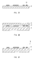
- a photosensitive resin composition 7 is disposed on a surface of a resin porous membrane 2 as shown in Fig. 1A .
- a portion of the resin composition 7 disposed on the surface of the porous membrane 2 is irradiated with a light that cures the resin composition 7, as shown in Fig. 1B , so that the irradiated portion of the resin composition 7 is cured.
- irradiating the photosensitive resin composition with a light that cures the composition is expressed as "to expose to the light”.
- the light irradiation shown in Fig. 1B also can be expressed as a portion of the composition being exposed to the light (exposure treatment).
- the exposure treatment allows the resin composition 7 to have exposed portions (cured portions) 21 and unexposed portions (uncured portions) 22 on the surface of the porous membrane 2.
- a photomask 11 with opening portions 13 is disposed between a source of the light and the resin composition 7 so that the resin composition 7 is irradiated with the light passing through the opening portions 13. Accordingly, the resin composition 7 is cured in portions corresponding to the shapes of the opening portions 13. This means the cured portions 21 corresponding to the shapes of the opening portions 13 are formed.
- a resin porous membrane with an adhesive layer (a first porous membrane) 5 having the adhesive bodies as the adhesive layer can be obtained.
- the photosensitive resin composition 7 is disposed on a surface of a transfer substrate 31 as shown in Fig. 2A .
- a portion of the resin composition 7 disposed on the surface of the substrate 31 is irradiated with the light that cures the resin composition 7, as shown in Fig. 2B , so that the irradiated portion of the resin composition 7 is cured (exposure treatment).
- the exposure treatment allows the resin composition 7 to have the cured portions 21 and the uncured portions 22 on the surface of the substrate 31.
- the resin porous membrane with the adhesive layer (the first porous membrane) 5 can be obtained that has on the surface thereof the adhesive bodies as the adhesive layer ( Fig. 2F ).
- the method shown in Fig. 1A to Fig. 1D and the method shown in Fig. 2A to Fig. 2F make it possible to determine arbitrarily the shape of the light applied to the photosensitive resin composition 7 by changing the shapes of the opening portions 13 of the photomask 11, and/or by controlling an optical system. That is, by applying the exposure and development treatments to the resin composition 7 disposed on the surface of the porous membrane 2 or the surface of the substrate 31, it is possible to form the first porous membrane having on the surface thereof the arbitrarily-shaped adhesive bodies 6 as the adhesive layer.
- the methods also allow the adhesive bodies 6 to have a very fine shape.
- the adhesive bodies 6 may have a width less than 1 mm, and 500 ⁇ m or less or 250 ⁇ m or less in some cases, and furthermore, 150 ⁇ m or less, for example.
- the adhesive bodies 6 may have a strip shape with a width of 1 mm or less, and in some cases 500 ⁇ m or less or 250 ⁇ m or less, and furthermore 150 ⁇ m or less, for example.
- the lower limit of the width of the adhesive bodies 6 is not particularly limited, and is approximately 20 ⁇ m, for example, although it varies depending on the type of the photosensitive resin composition 7.
- a cut adhesive tape is bonded to the porous membrane, or an adhesive is applied to the porous membrane by a technique such as printing. It is difficult, however, to process the adhesive tape into a fine size to have, for example, a width of less than 1 mm because of a problem such as its adhesion to a punching die or a cutting blade. Even when a method is employed in which the adhesive is applied to the surface of the porous membrane by a technique such as printing, it is not possible to apply the adhesive to the surface of the porous membrane in such a manner that the adhesive is applied in a width of less than 1 mm because of high viscosity of the adhesive.
- the first and second production methods of the present invention make it possible to form the resin porous membrane with the adhesive layer 5 having on the surface thereof the unconventionally fine-shaped adhesive bodies 6 as the adhesive layer.
- the resin porous membrane with the adhesive layer thus formed is easy to handle when being bonded to the adherend even in the case where the porous membrane 2 is small.
- the first and second production methods of the present invention allow the porous membrane 2 to ensure its gas permeability at the portions from which the photosensitive resin composition 7 has been removed by the development treatment.
- the first and second production methods of the present invention make it possible to form the resin porous membrane with the adhesive layer that exhibits excellent bonding precision, and can be bonded to the adherend while maintaining the gas permeability of the porous membrane 2 even when the porous membrane 2 is small.
- the "width" of the adhesive body 6 in the specification means a dimension of the adhesive body in a direction of a shorter side (or a shorter axis) thereof when viewed from a direction perpendicular to the surface of the porous membrane 2 on which the adhesive body 6 is disposed.
- the dimension in the shorter side direction is referred to as "width”
- a dimension in a longer side direction is referred to as "length”.
- the method for arranging the photosensitive resin composition on the surface of the porous membrane 2 or the surface of the substrate 31 is not particularly limited.
- the method may be as follows.
- the photosensitive resin composition is dissolved in an appropriate solvent (an example thereof is an organic solvent, such as dioxane and cyclohexane) to form a solution.
- the solution thus formed is applied to a base film, such as a resin film, by a common coating method, such as a spin coat method.
- the solvent is removed by a technique, such as drying, to form a photosensitive resin layer.
- the photosensitive resin layer thus formed is transferred from the base film to the surface of the porous membrane 2 or the surface of the substrate 31.
- the photosensitive resin composition may be disposed on the surface of the substrate 31 through applying the solution to the surface of the substrate 31 and removing the solvent.
- the method for transferring the photosensitive resin layer is not particularly limited.
- the method may be as follows.
- the porous membrane 2 is stacked on the base film with the photosensitive resin layer in such a manner that the photosensitive resin layer is in contact with the porous membrane 2, and pressure is applied in a direction that brings both of them into a close contact with each other. At this time, heat also may be applied, if needed.
- the method for applying the exposure treatment to the resin composition 7 disposed on the surface of the porous membrane 2 or the surface of the substrate 31 is not particularly limited, and a known method (for example, a photolithography method) can be used.
- Examples of the light used in the exposure treatment include ultraviolet ray, electron ray, and microwave, although it depends on the type of the resin composition 7.
- the wavelength, energy, and amount of the light may be selected suitably depending on the type of the resin composition 7, desired shape and size of the adhesive body 6, etc.
- the photomask 11 is used for the exposure treatment in the examples shown in Fig. 1B and Fig. 2B , a light shielding member other than the photomask may be used.
- the exposure treatment on the resin composition 7 may be performed without using the shielding body such as the photomask, and may be performed, for example, only by controlling the optical system of the light to be applied, depending on the desired size and shape of the adhesive body 6.
- Use of the shielding body, such as the photomask, in the exposure treatment makes it possible to form on the surface of the porous membrane 2 the adhesive bodies 6 with a fine shape and/or a fine arrangement pattern.
- the method for applying the development treatment to the resin composition 7 after the exposure treatment is not particularly limited, and a known method (for example, a photolithography method) can be used. More specifically, the surface of the porous membrane 2 may be washed with a solvent (a developer, such as N-methyl-2-pyrrolidone and methyl ethyl ketone) that dissolves selectively the uncured portions 22 resulting from the exposure treatment.
- a solvent a developer, such as N-methyl-2-pyrrolidone and methyl ethyl ketone
- a heat treatment such as a so-called post exposure bake (PEB) may be provided between the exposure treatment and the development treatment, if needed.
- PEB post exposure bake
- the transferring method in the second production method is not particularly limited.
- the method may be as follows.
- the transfer substrate 31 is stacked on the porous membrane 2 in such a manner that the cured portions 21 left on the surface of the substrate 31 are in contact with the porous membrane 2, and pressure is applied in a direction that brings the cured portions 21 and the porous membrane 2 into a close contact with each other. At this time, heat also may be applied, if needed.
- FIG. 3 shows an example of a resin porous membrane with an adhesive layer (a second porous membrane) of the present invention.
- a resin porous membrane with an adhesive layer 1 shown in Fig. 3 has a structure in which an adhesive layer 3 is disposed on the surface of the porous membrane 2.
- the adhesive layer 3 comprises the photosensitive resin composition.
- the adhesive layer 3 is disposed on one of the principal surfaces of the porous membrane 2 in such a manner that the adhesive layer 3 covers the principal surface entirely.
- a separator 4 that can be stripped off easily from the adhesive layer 3 is disposed on a principal surface of the adhesive layer 3 on a side opposite to the porous membrane 2 side.
- the resin porous membrane with the adhesive layer 1 can be obtained as an intermediate product in the first production method, and can be circulated in the market as it is.
- the laminate body shown in Fig. 1A constituted by the porous membrane 2 and the photosensitive resin composition 7 corresponds to the resin porous membrane with the adhesive layer 1.
- the exposure treatment and the development treatment are applied to the adhesive layer 3 to form the adhesive body on the surface of the porous membrane 2.
- the adhesive body has a shape corresponding to the shape of the light applied in the exposure treatment. That is, applying the exposure treatment and the development treatment to the adhesive layer 3 makes it possible to form the resin porous membrane with the adhesive layer (the first porous membrane) 5.
- the adhesive body obtained by exposing the photosensitive resin composition to the light is disposed on the surface of the porous membrane as the adhesive layer.
- the thickness of the adhesive layer 3 is not particularly limited. Usually, it is approximately 10 ⁇ m to 100 ⁇ m in order to perform the exposure treatment and the development treatment in a more reliable manner., and preferably 15 ⁇ m to 50 ⁇ m.
- the adhesive layer 3 is disposed on one of the principal surfaces of the porous membrane 2 in such a manner that the adhesive layer 3 covers the principal surface entirely.
- the adhesive layer 3 does not necessarily have to be disposed like this, and it may be disposed on the surface of the porous membrane 2 in such a manner that it covers the surface partially.
- the porous membrane 2 may have, at a periphery thereof, a portion at which the adhesive layer 3 is not disposed.
- the separator 4 may be provided on an if-needed basis. Providing the separator 4 to the resin porous membrane with the adhesive layer 1 makes it easier to handle the resin porous membrane with the adhesive layer 1, and promotes the circulation of the resin porous membrane with the adhesive layer 1 in the market.
- the separator 4 preferably has high transparency to the light that is applied to the adhesive layer 3 in the exposure treatment. In this case, the exposure treatment can be applied while the separator 4 is present.
- the separator 4 is made of resin.
- the resin porous membrane with the adhesive layer 1 can be formed by providing the photosensitive resin composition on the surface of the porous membrane 2.
- the method for providing the photosensitive resin composition complies with the method for providing the photosensitive resin composition on the surface of the porous membrane 2 in the first and the second production methods. In this method, after the photosensitive resin layer is transferred to the porous membrane, the base film used may not be stripped off but remain as it is to serve as the separator 4, depending on the type of the base film.
- Fig. 4 shows an example of the resin porous membrane with the adhesive layer (the first porous membrane) of the present invention.
- the resin porous membrane with the adhesive layer 5 shown in Fig. 4 has a structure in which the adhesive bodies 6 obtained by exposing the photosensitive resin composition to the light are disposed on the surface of the porous membrane 2 as the adhesive layer.
- the adhesive bodies 6 are strip-shaped bodies extending in one direction on the principal surface of the porous membrane 2. Two or more of the adhesive bodies 6 are disposed on the surface of the porous membrane 2 in such a manner that they are parallel to each other (in a stripe pattern).
- the resin porous membrane with the adhesive layer 5 can be formed, for example, by the first and the second production methods, or by applying the exposure treatment and the development treatment to the first porous membrane 1.
- the adhesive bodies 6 thus formed can have a fine shape.
- the adhesive bodies 6 may have a width less than 1 mm, and in some cases 500 ⁇ m or less or 250 ⁇ m or less, and furthermore 150 ⁇ m or less.
- the resin porous membrane with the adhesive layer 5 having on the surface thereof the fine-shaped adhesive bodies 6 is easy to handle when being bonded to the adherend, and allows the porous membrane 2 to ensure its gas permeability at the portions where the adhesive bodies 6 are not present. This means that even when the porous membrane 2 is small, the resin porous membrane with the adhesive layer 5 has an excellent bonding precision, and can be bonded to the adherend while maintaining the gas permeability of the porous membrane 2.
- the adhesive bodies 6 are disposed on the surface of the porous membrane 2 in a stripe pattern.
- the shape, quantity, and arrangement pattern etc. of the adhesive bodies 6 are not particularly limited.
- the single, annular adhesive body 6 may be disposed on the surface of the porous membrane 2 ( Fig. 5 ), or two or more of the rectangular adhesive bodies 6 may be disposed on the surface of the porous membrane 2 ( Fig. 6 ) in such a manner that the adhesive bodies constitute each side of one rectangle, respectively, when viewed from a direction perpendicular to the surface of the porous membrane 2 on which the adhesive bodies 6 are disposed.
- the rectangular adhesive bodies 6 and the annular adhesive body 6 may be disposed in combination on the surface of the porous membrane 2 ( Fig. 7 ). It can be said that all of the annular and rectangular adhesive bodies 6 shown in Figs. 5 to 7 are strip-shaped bodies.
- the width ( ⁇ shown in Figs. 5 and 6 ) of the resin porous membrane with the adhesive layer 5 can be set to less than 1 mm, and in some cases 500 ⁇ m or less or 250 ⁇ m or less, and furthermore 150 ⁇ m or less.
- the adhesive bodies 6 may be disposed on both of the principal surfaces of the porous membrane 2 as shown in Fig. 8 .
- the shape, quantity, and arrangement pattern of the adhesive bodies 6 disposed on one of the principal surfaces and those of the adhesive bodies 6 disposed on the other principal surface may be the same or different.
- the precision in bonding the resin porous membrane with the adhesive layer 5 to the adherend can be enhanced further by selecting the shape and/or the arrangement pattern of the adhesive bodies 6 according to the material and the shape of the adhesion surface of the adherend to which the resin porous membrane with the adhesive layer 5 is bonded.
- the arrangement pattern of the adhesive layer can be more intricate than that in conventional methods in which an adhesive tape is disposed on or an adhesive is applied to the surface of the porous membrane.
- the type of the photosensitive resin composition is not particularly limited, and may be an epoxy resin composition, for example.
- the epoxy resin composition include a resin composition comprising an epoxy resin, and a substance that accelerates curing of the epoxy resin under light irradiation, such as a photoacid generator.
- the photosensitive resin composition preferably is a resin composition (a resin composition (C)) comprising a polyfunctional epoxy resin (A) having an epoxy equivalent of 100 g/eq to 300 g/eq, and a polyfunctional epoxy resin (B) having an epoxy equivalent of 450 g/eq to 10000 g/eq, and a photoacid generator.
- a resin composition (C) comprising a polyfunctional epoxy resin (A) having an epoxy equivalent of 100 g/eq to 300 g/eq, and a polyfunctional epoxy resin (B) having an epoxy equivalent of 450 g/eq to 10000 g/eq, and a photoacid generator.
- the resin (A) with a relatively small epoxy equivalent has high wettability and flowability when being heated and maintains them even after being exposed to the light, and because the resin (B) with a relatively large epoxy equivalent has morphological stability during the exposure treatment.
- the type of the resin (A) is not particularly limited as long as it is a polyfunctional epoxy resin whose epoxy equivalent is in the range of 100 g/eq to 300 g/eq.
- a glycidyl ether epoxy resin is preferable, and particularly, a glycidyl ether epoxy resin of bisphenol A type, bisphenol F type, biphenyl type, novolak type, or fluorene type can be used suitably.
- the type of the resin (B) is not particularly limited as long as it is a polyfunctional epoxy resin whose epoxy equivalent is in the range of 450 g/eq to 10000 g/eq.
- a bisphenol A type phenoxy resin or a bisphenol F type phenoxy resin can be used suitably.
- "Phenoxy resin” is an epoxy resin with an increased molecular weight, obtained by allowing epichlorohydrin to react with bisphenol A or bisphenol F.
- the amounts of the resin (A) and the resin (B) comprised in the resin composition (C) are not particularly limited. Usually, the amount of the resin (A) is approximately 5 to 90 parts by weight (preferably 10 to 60 parts by weight), and the amount of the resin (B) is approximately 10 to 95 parts by weight (preferably 40 to 90 parts by weight), when the weight of the entire epoxy resin comprised in the resin composition (C) is taken as 100 parts by weight.
- the type of the photoacid generator is not particularly limited as long as it generates acid when being irradiated with light, and the generated acid accelerates curing of the epoxy resin.
- a triaryl sulfonium salt, a diaryl iodonium salt, etc. for which various onium salts, particularly, BF 4 , PF 6 , AsF 6 , SbF 6 , serve as a counter anion may be used as the photoacid generator.
- the photoacid generator is included in the photosensitive resin composition with respect to 100 parts by weight of the epoxy resin.
- the photosensitive resin composition such as the resin composition (C) may comprise, as needed, various kinds of additives such as a flame retardant, a release agent, and a leveling agent, that conventionally have been added to photosensitive resin compositions in some cases.
- additives such as a flame retardant, a release agent, and a leveling agent, that conventionally have been added to photosensitive resin compositions in some cases.
- the ratio of unreacted epoxy in the composition after the exposition treatment is completed (that is, the ratio of unreacted epoxy in the adhesive body 6 obtained by exposing the epoxy resin composition to the light) preferably is in the range of 15% to 60%, and more preferably in the range of 20% to 50%.
- the unreacted epoxy ratio of less than 15% may deteriorate the adhesiveness of the adhesive bodies 6, depending on the specific composition of the epoxy resin composition.
- the unreacted epoxy ratio exceeding 60% may deteriorate the shape retentivity of the adhesive bodies 6.
- the unreacted epoxy ratio can be measured, for example, on a film-like measurement specimen by conducting an FT-IR (Fourier transform infrared spectroscopy) analysis using an ATR method (attenuated total reflectance method). Specifically, when a peak due to a benzene ring appearing at around a wavelength of 1600 cm -1 is taken as a reference peak, a peak due to epoxy unit is measured at around a wavelength of 910 cm -1 before the exposure and after the exposure (after the heat treatment when the heat treatment such as a post exposure bake (PEB) is performed between the exposure treatment and the development treatment, ) so as to calculate a ratio of a peak height h2 after the exposure to a peak height h1 before the exposure by (h2/h1) ⁇ 100 (%). This ratio can be used as the unreacted epoxy ratio.
- the epoxy resin composition is free from substances containing a benzene ring
- the reference peak is measured on a reference substance containing a benzene ring.
- the configuration of the resin porous membrane 2 is not particularly limited.
- the resin porous membrane 2 comprises preferably at least one selected from a fluororesin porous body and a polyolefin porous body.
- a porous body composed of a material such as polytetrafluoroethylene (PTFE), a tetrafluoroethylene-hexafluoropropylene copolymer (FEP), a tetrafluoroethylene-perfluoroalkyl vinyl ether copolymer (PFA), and a tetrafluoroethylene-ethylene copolymer (ETFE).
- PTFE polytetrafluoroethylene
- FEP tetrafluoroethylene-hexafluoropropylene copolymer
- PFA tetrafluoroethylene-perfluoroalkyl vinyl ether copolymer
- ETFE tetrafluoroethylene-ethylene copolymer
- the polyolefin porous body there can be mentioned, for example, a porous body composed of a polymer or a copolymer of various kinds of olefin monomers, such as ethylene, propylene, 4-methylpentene-1, 1-butene.
- the porous membrane 2 it is preferable for the porous membrane 2 to comprise the PTFE porous body that exhibits satisfactory gas permeability even in a small ventilation area and can suppress permeation of liquid.
- the porous membrane 2 comprising the PTFE porous body allows a circuit board of an electronic device to have a reflow soldering after the resin porous membrane with the adhesive layer comprising the porous membrane 2 is bonded to the circuit board.
- the resin porous membrane with the adhesive layer comprising the porous membrane 2 is applied suitably to water proof gas permeable filters used for electronic devices such as cellular phones.
- the porous membrane 2 may comprise a reinforcing layer made of nonwoven fabric, woven fabric, etc., if needed.
- a reinforcing layer made of nonwoven fabric, woven fabric, etc.
- various kinds of surface treatments such as a water-repellent treatment, an oil-repellent treatment, and an antibacterial treatment, may be applied.
- the resin porous membrane with the adhesive layer 5 is brought into contact with the adherend in such a manner that the adhesive bodies 6 are in contact with the adherend, and the contact areas of the adhesive bodies 6 and the adherend are heated while the adhesive bodies 6 and the adherend are kept in contact with each other.
- pressure may be applied, as needed, in a direction that brings the porous membrane with the adhesive layer 5 into close contact with the adherend, while their contact areas are heated.
- the heating temperature is not particularly limited.
- the contact areas may be heated at approximately 20°C to 200°C, preferably at approximately 100°C to 160°C.
- the heating method is not particularly limited.
- the contact areas may be heated from the porous membrane 2 side, or the entire unit including the adherend and the resin porous membrane with the adhesive layer 5 may be put in a heating furnace maintained at a predetermined temperature to heat the contact areas.
- the configuration of the filter member of the present invention is not particularly limited as long as the filter member includes the resin porous membrane with the adhesive layer of the present invention.
- the filter member of the present invention may include the resin porous membrane with the adhesive layer, and a support body that is made of metal or resin and supports the resin porous membrane. When the support body has gas permeability, the resin porous membrane can be stacked on the support body.
- An adhesive layer of the filter member can be bonded to various kinds of adherends, such as a housing of an electronic device, a circuit board, and a support frame of a filter. In this way, the filter member of the present invention can be used for various kinds of adherends.
- the filter member of the present invention can be used as various kinds of filters, such as filters for clean rooms, filters for dust catchers, and water proof gas permeable filters and sound pressure adjusting filters used in electronic devices such as cellular phones.
- the bonding method of the present invention exhibits higher bonding precision than that of the conventional bonding methods, and can bond the porous membrane to the adherend while maintaining the gas permeability of the porous membrane.
- the porous membrane having on the surface thereof the adhesive body may be formed by: arranging the photosensitive resin composition on the surface of the resin porous membrane; and exposing a portion of the resin composition to the light, and then removing an unexposed portion of the resin composition so that the exposed portion remained on the surface of the resin porous membrane serves as the adhesive body.
- the porous membrane having on the surface thereof the adhesive body may be formed by: arranging the photosensitive resin composition on the surface of the transfer substrate; exposing a portion of the resin composition to the light, and then removing an unexposed portion of the resin composition; and transferring to the surface of the resin porous membrane the exposed portion remained on the surface of the substrate so that the transferred portion of the resin composition serves as the adhesive body.
- Example 2 a PTFE porous body (NTF1133, produced by Nitto Denko Corp., with a thickness of 85 ⁇ m, a porosity of 82%, and a air permeability of 1 second/100 cc) was used as the porous membrane 2.
- the permeability shows a value obtained by a measurement according to JIS P8117 (air permeance test method - Gurley method).
- Fig. 9 shows an image taken when the surface of the porous membrane 2 was observed with a scanning electron microscope (SEM) (an SEM image of the surface of the porous membrane 2).
- SEM scanning electron microscope
- the varnish thus prepared was applied to a polyethylene naphthalate (PET) film, and placed and dried in a heating furnace maintained at 80°C to form a PET film having on a surface thereof a 25 ⁇ m-thick photosensitive resin layer.
- PET polyethylene naphthalate
- the PET film with the photosensitive resin layer thus formed and the porous membrane 2 were made go through between a pair of rollers heated at 90°C while being kept in contact with each other to transfer the photosensitive resin layer from the PET film to the surface of the porous membrane 2.
- the exposure treatment using ultraviolet ray was applied to the porous membrane with the adhesive layer 1 thus formed, using a photomask with opening portions (each having a width of 150 ⁇ m) arranged in a shape of an outline of a rectangle.
- a high pressure mercury vapor lamp was used as the source of the irradiation light, and the quantity of the irradiation light was set to 800 mJ/cm 2 .
- the whole unit was heated at 90°C for 10 minutes, and then the porous membrane 2 was immersed in a developer composed of N-methyl-2-pyrrolidone for 6 minutes.
- the porous membrane 2 was immersed further in a developer composed of methyl ethyl ketone to have the development treatment.
- the porous membrane 2 having on the surface thereof the adhesive bodies 6 with a shape corresponding to the shape of the opening portions of the photomask, that is, the resin porous membrane with the adhesive layer (the first porous membrane) 5, was prepared.
- Fig. 10A shows an SEM image of the surface of the resin porous membrane with the adhesive layer 5 thus prepared. It was confirmed that, as shown in Fig. 10A , in the resin porous membrane with the adhesive layer 5, a plurality of the adhesive bodies 6 were formed on the surface of the porous membrane 2, and the adhesive bodies 6 had a width of 150 ⁇ m and were arranged in a shape of a rectangular outline corresponding to the shape of the opening portions of the photomask.
- Fig. 10B is an SEM image showing an enlarged view of Portion A on the surface of the porous membrane 2 in Fig. 10A .
- Portion A is a portion at which the photosensitive resin composition had been removed by the development treatment and the porous membrane 2 was bare. It was confirmed that, as shown in Fig. 10B , in the portion where the photosensitive resin composition had been removed by the development treatment, the pores of the porous membrane 2 were not clogged, and that the porous membrane 2 still had the surface almost the same as the surface shown in Fig. 9 , which is the surface before the photosensitive resin layer was formed thereon.
- the resin porous membrane with the adhesive layer 5 thus prepared was brought into contact with the adherend constituted by a glass sheet having a through hole with a diameter of 3 mm ⁇ in such a manner that the adhesive bodies 6 and the glass sheet were in contact with each other.
- the whole unit was put in the heating furnace maintained at 100°C while a pressure of 5 MPa was applied in a direction that brings the adhesive bodies 6 into close contact with the glass sheet, and the whole unit was heated for 10 seconds.
- the adhesive bodies 6 were brought into contact with the glass sheet in such a manner that the porous membrane 2 covered the through hole but the adhesive bodies 6 on the porous membrane 2 did not overlap with the through hole.
- the bonding status between the adhesive bodies 6 and the glass sheet was checked visually after they were cooled. No deformation was observed on the adhesive bodies 6, and the porous membrane 2 was bonded to the surface of the glass sheet via the entire surfaces of the adhesive bodies 6. Also, air was blown through the through hole provided in the glass sheet. The air was able to be discharged through the porous membrane 2, and it was confirmed that the gas permeability of the porous membrane 2 was ensured.
- the glass sheet with the porous membrane 2 bonded thereto was put for 10 seconds in the heating furnace maintained at 260°C. Separation, displacement, etc. of the porous membrane 2 from the glass sheet were not observed.
- a double-sided adhesive tape (a 50 ⁇ m-thick polyester film on both sides of which a 20 ⁇ m-thick thermosensitive polyacrylate adhesive was applied) was tried to be punched out into a 700 ⁇ m-wide rectangle to be used as an adhesive.
- the adhesive adhered to the punching die making it impossible to punch out the double-sided adhesive tape into the aforementioned shape.
- the present invention provides the resin porous membrane with the adhesive layer that exhibits excellent bonding precision and can be bonded to the adherend while maintaining the gas permeability of the porous membrane even when the porous membrane is small.
- the present invention also provides the filter member including the resin porous membrane with the adhesive layer.
- the filter member of the present invention can be used suitably as various kinds of filters, such as filters for clean rooms, filters for dust catchers, and water proof gas permeable filters and sound pressure adjusting filters used in electronic devices such as cellular phones.
Landscapes
- Chemical & Material Sciences (AREA)
- Chemical Kinetics & Catalysis (AREA)
- Organic Chemistry (AREA)
- Engineering & Computer Science (AREA)
- Textile Engineering (AREA)
- Optics & Photonics (AREA)
- Manufacturing & Machinery (AREA)
- Physics & Mathematics (AREA)
- Separation Using Semi-Permeable Membranes (AREA)
- Laminated Bodies (AREA)
- Adhesives Or Adhesive Processes (AREA)
- Filtering Materials (AREA)
- Manufacture Of Porous Articles, And Recovery And Treatment Of Waste Products (AREA)
- Lining Or Joining Of Plastics Or The Like (AREA)
- Adhesive Tapes (AREA)
Abstract
Description
- The present invention relates to a resin porous membrane having on a surface thereof an adhesive layer, and a method for producing the resin porous membrane with the adhesive layer. The present invention also relates to a filter member including the resin porous membrane with the adhesive layer.
- Today, resin porous membranes (hereinafter, also referred to simply as "porous membranes") are applied widely to filters. Particularly, porous membranes made of polytetrafluoroethylene (PTFE), that is, PTFE porous membranes, have excellent heat resistance, chemical stability, electrical insulation, water repellency, and oil repellency, which are characteristics derived from PTFE. When the PTFE porous membranes are used as a filtering medium of a filter, dust hardly is generated, and both a low pressure loss and a high collection efficiency can be achieved at the same time. Thus, the PTFE porous membranes are used widely for filters, such as filters for clean rooms, filters for dust catchers, and water proof gas permeable filters and sound pressure adjusting filters used in electronic devices such as cellular phones. The PTFE porous membranes increasingly have been used as the water proof gas permeable filters in particular that can transfer sound while preventing liquid from contacting a transducer (a transmitter and a receiver) of a cellular phone.
- When the PTFE porous membrane is used for any of these applications, particularly for an electronic device, the porous membrane is bonded directly to a base component constituting the device, such as a housing, in many cases. When the porous membrane is bonded to the base component, it is important to ensure the gas permeability of the porous membrane.
- As common conventional methods for bonding the porous membrane to the base component, there can be mentioned a method in which an adhesive material processed into a predetermined shape is disposed on a surface of the porous membrane or a surface of the base component, and a method in which the porous membrane and the base component are welded thermally to each other, although the latter is possible only when the base component is made of thermoplastic resin. For example,
JP 2003-503991 T - In recent years, as electronic devices have been downsized and highly integrated, the porous membranes to be bonded to their base components are required strongly to be smaller. With an intent to achieve further downsizing and higher integration of the electronic devices, it also has been required to dispose electronic parts, such as a transducer, directly on a circuit board as well as to arrange the porous membrane in such a manner that the porous membrane covers the electronic parts. That is, it also has been required to bond the porous membrane directly to the circuit board.
- However, it is difficult to bond the smaller porous membrane to the base component while ensuring the gas permeability of the porous membrane by using the conventional bonding methods because they have limitations in reducing the size of the adhesive material to be disposed on the porous membrane, and in reducing the amount of the adhesive applied to the porous membrane. Moreover, the size reduction of the porous membrane, on which the adhesive material is disposed (on which the adhesive is applied), makes it difficult to handle, and lowers the precision in bonding the porous membrane to the base component. Furthermore, when the adherend is a circuit board, it is not possible to bond the porous membrane thereto by thermal welding because circuit boards usually are made of thermosetting resin.
- The present invention is intended to provide a resin porous membrane with an adhesive layer that exhibits excellent bonding precision and can be bonded to the adherend while maintaining the gas permeability of the porous membrane even when the porous membrane is small in size, and to provide a method for producing the resin porous membrane. The present invention also is intended to provide a filter member including the resin porous membrane with the adhesive layer.
- The method for producing the resin porous membrane with the adhesive layer (a first production method) of the present invention is a method for producing a resin porous membrane with an adhesive layer, having on a surface thereof an adhesive body as the adhesive layer. The first production method of the present invention comprises the steps of: disposing a photosensitive resin composition on the surface of the resin porous membrane; and exposing a portion of the resin composition to light, and then removing an unexposed portion of the resin composition so that the exposed portion remaining on the surface of the resin porous membrane serves as the adhesive body.
- In another aspect, the method for producing the resin porous membrane with the adhesive layer (a second production method) of the present invention is a method for producing a resin porous membrane with an adhesive layer, having on a surface thereof an adhesive body as the adhesive layer. The second production method of the present invention comprises the steps of: disposing a photosensitive resin composition on a surface of a transfer substrate; exposing a portion of the resin composition to light, and then removing an unexposed portion of the resin composition; and transferring to the surface of the resin porous membrane the exposed portion remained on the surface of the substrate so that the transferred portion of the resin composition serves as the adhesive body.
- In the resin porous membrane with the adhesive layer (a first porous membrane) of the present invention, the adhesive layer is disposed on the surface of the resin porous membrane, and the adhesive body obtained by exposing the photosensitive resin composition to light is disposed as the adhesive layer. The first porous membrane can be obtained by, for example, the first production method or the second production method.
- In the resin porous membrane with the adhesive layer of the present invention in another aspect (a second porous membrane), the adhesive layer is disposed on the surface of the resin porous membrane, and the adhesive layer comprises the photosensitive resin composition. The second porous membrane can be obtained, for example, as an intermediate product in the first production method. By having the below-mentioned exposure treatment and development treatment, the second porous membrane becomes the resin porous membrane with the adhesive layer, having on the surface thereof the arbitrarily-shaped adhesive body as the adhesive layer. At this time, since the adhesive body is an adhesive body obtained by exposing the photosensitive resin composition to light, the resulting resin porous membrane with the adhesive layer is the first porous membrane.
- The filter member of the present invention includes the resin porous membrane with the adhesive layer of the present invention.
- The bonding method for the resin porous membrane of the present invention is a method for bonding the porous membrane to the adherend by bringing the porous membrane, which has on the surface thereof the adhesive body obtained by exposing the photosensitive resin composition to light, into contact with the adherend in such a manner that the adhesive body is in contact with the adherend, and by heating the contact area of the adhesive body and the adherend while keeping the adhesive body and the adherend in contact with each other so as to bond the resin porous membrane to the adherend.
- The production method of the present invention makes it possible to produce the resin porous membrane with the adhesive layer that exhibits excellent bonding precision and can be bonded to the adherend while maintaining the gas permeability of the porous membrane even when the porous membrane is small, by using the method (the first production method) in which a portion of the photosensitive resin composition disposed on the surface of the resin porous membrane is exposed to light so that the portion cured by the exposure in the resin composition serves as the adhesive body, or by using the method (the second production method) in which a portion of the photosensitive resin composition disposed on the surface of the transfer substrate is exposed to light, and the portion cured by the exposure in the resin composition is transferred to the surface of the resin porous membrane so that the transferred portion of the resin composition serves as the adhesive body.
-
-
Fig. 1A is a cross-sectional view showing schematically a process in an example of the first production method of the present invention. -
Fig. 1B is a cross-sectional view showing schematically a process following the process shown inFig. 1A . -
Fig. 1C is a cross-sectional view showing schematically a process following the process shown inFig. 1B . -
Fig. 1D is a cross-sectional view showing schematically a process following the process shown inFig. 1C . -
Fig. 2A is a cross-sectional view showing schematically a process in an example of the second production method of the present invention. -
Fig. 2B is a cross-sectional view showing schematically a process following the process shown inFig. 2A . -
Fig. 2C is a cross-sectional view showing schematically a process following the process shown inFig. 2B . -
Fig. 2D is a cross-sectional view showing schematically a process following the process shown inFig. 2C . -
Fig. 2E is a cross-sectional view showing schematically a process following the process shown inFig. 2D . -
Fig. 2F is a cross-sectional view showing schematically a process following the process shown inFig. 2E . -
Fig. 3 is a perspective view showing an example of the second porous membrane of the present invention. -
Fig. 4 is a perspective view showing an example of the first porous membrane of the present invention. -
Fig. 5 is a plan view showing an example of the shape and arrangement pattern of the adhesive bodies in the first porous membrane of the present invention. -
Fig. 6 is a plan view showing an example of the shape and arrangement pattern of the adhesive bodies in the first porous membrane of the present invention. -
Fig. 7 is a plan view showing an example of the shape and arrangement pattern of the adhesive bodies in the first porous membrane of the present invention. -
Fig. 8 is a perspective view showing an example of the first porous membrane of the present invention. -
Fig. 9 is a view showing a scanning electron microscope (SEM) image of the surface of the porous membrane used in Example. -
Fig. 10A is a view showing an SEM image of the surface of the first porous membrane produced in Example. -
Fig. 10B is an enlarged view of Portion A on the surface of the first porous membrane shown inFig. 10A . - Embodiments of the present invention will be described with reference to the drawings. In the following description, the same members are indicated by the same reference numerals and repetitive description thereof may be omitted.
- An example of the first production method of the present invention will be described with reference to
Fig. 1A to Fig. 1D . - First, a
photosensitive resin composition 7 is disposed on a surface of a resinporous membrane 2 as shown inFig. 1A . Next, a portion of theresin composition 7 disposed on the surface of theporous membrane 2 is irradiated with a light that cures theresin composition 7, as shown inFig. 1B , so that the irradiated portion of theresin composition 7 is cured. In the specification, irradiating the photosensitive resin composition with a light that cures the composition is expressed as "to expose to the light". The light irradiation shown inFig. 1B also can be expressed as a portion of the composition being exposed to the light (exposure treatment). As shown inFig. 1C , the exposure treatment allows theresin composition 7 to have exposed portions (cured portions) 21 and unexposed portions (uncured portions) 22 on the surface of theporous membrane 2. - In the example shown in
Fig. 1B , aphotomask 11 with openingportions 13 is disposed between a source of the light and theresin composition 7 so that theresin composition 7 is irradiated with the light passing through the openingportions 13. Accordingly, theresin composition 7 is cured in portions corresponding to the shapes of the openingportions 13. This means the curedportions 21 corresponding to the shapes of the openingportions 13 are formed. - Next, as shown in
Fig. 1D , theuncured portions 22 of theresin composition 7 are removed (development treatment), and the curedportions 21 left on the surface of theporous membrane 2 serve asadhesive bodies 6. Thus, a resin porous membrane with an adhesive layer (a first porous membrane) 5 having the adhesive bodies as the adhesive layer can be obtained. - An example of the second production method of the present invention will be described with reference to
Fig. 2A to Fig. 2F . - First, the
photosensitive resin composition 7 is disposed on a surface of atransfer substrate 31 as shown inFig. 2A . Next, a portion of theresin composition 7 disposed on the surface of thesubstrate 31 is irradiated with the light that cures theresin composition 7, as shown inFig. 2B , so that the irradiated portion of theresin composition 7 is cured (exposure treatment). As shown inFig. 2C , the exposure treatment allows theresin composition 7 to have the curedportions 21 and theuncured portions 22 on the surface of thesubstrate 31. , - Next, the
uncured portions 22 of theresin composition 7 are removed (development treatment). This treatment leaves the curedportions 21 on the surface of thesubstrate 31. - Subsequently, as shown in
Fig. 2E , the curedportions 21 left on the surface of thesubstrate 31 are transferred to the surface of theporous membrane 2, and the curedportions 21 transferred to the surface of theporous membrane 2 serve as theadhesive bodies 6. Thus, the resin porous membrane with the adhesive layer (the first porous membrane) 5 can be obtained that has on the surface thereof the adhesive bodies as the adhesive layer (Fig. 2F ). - The method shown in
Fig. 1A to Fig. 1D and the method shown inFig. 2A to Fig. 2F make it possible to determine arbitrarily the shape of the light applied to thephotosensitive resin composition 7 by changing the shapes of the openingportions 13 of thephotomask 11, and/or by controlling an optical system. That is, by applying the exposure and development treatments to theresin composition 7 disposed on the surface of theporous membrane 2 or the surface of thesubstrate 31, it is possible to form the first porous membrane having on the surface thereof the arbitrarily-shapedadhesive bodies 6 as the adhesive layer. - The methods also allow the
adhesive bodies 6 to have a very fine shape. Specifically, theadhesive bodies 6 may have a width less than 1 mm, and 500 µm or less or 250 µm or less in some cases, and furthermore, 150 µm or less, for example. Moreover, theadhesive bodies 6 may have a strip shape with a width of 1 mm or less, and in some cases 500 µm or less or 250 µm or less, and furthermore 150 µm or less, for example. The lower limit of the width of theadhesive bodies 6 is not particularly limited, and is approximately 20 µm, for example, although it varies depending on the type of thephotosensitive resin composition 7. - In the above-mentioned conventional bonding methods, a cut adhesive tape is bonded to the porous membrane, or an adhesive is applied to the porous membrane by a technique such as printing. It is difficult, however, to process the adhesive tape into a fine size to have, for example, a width of less than 1 mm because of a problem such as its adhesion to a punching die or a cutting blade. Even when a method is employed in which the adhesive is applied to the surface of the porous membrane by a technique such as printing, it is not possible to apply the adhesive to the surface of the porous membrane in such a manner that the adhesive is applied in a width of less than 1 mm because of high viscosity of the adhesive.
- In contrast, the first and second production methods of the present invention make it possible to form the resin porous membrane with the
adhesive layer 5 having on the surface thereof the unconventionally fine-shapedadhesive bodies 6 as the adhesive layer. The resin porous membrane with the adhesive layer thus formed is easy to handle when being bonded to the adherend even in the case where theporous membrane 2 is small. Also, the first and second production methods of the present invention allow theporous membrane 2 to ensure its gas permeability at the portions from which thephotosensitive resin composition 7 has been removed by the development treatment. That is, the first and second production methods of the present invention make it possible to form the resin porous membrane with the adhesive layer that exhibits excellent bonding precision, and can be bonded to the adherend while maintaining the gas permeability of theporous membrane 2 even when theporous membrane 2 is small. - It should be noted that the "width" of the
adhesive body 6 in the specification means a dimension of the adhesive body in a direction of a shorter side (or a shorter axis) thereof when viewed from a direction perpendicular to the surface of theporous membrane 2 on which theadhesive body 6 is disposed. For example, when the adhesive body is a strip-shaped body, the dimension in the shorter side direction is referred to as "width", and a dimension in a longer side direction is referred to as "length". - In the first and second production methods, the method for arranging the photosensitive resin composition on the surface of the
porous membrane 2 or the surface of thesubstrate 31 is not particularly limited. For example, the method may be as follows. The photosensitive resin composition is dissolved in an appropriate solvent (an example thereof is an organic solvent, such as dioxane and cyclohexane) to form a solution. The solution thus formed is applied to a base film, such as a resin film, by a common coating method, such as a spin coat method. The solvent is removed by a technique, such as drying, to form a photosensitive resin layer. And then, the photosensitive resin layer thus formed is transferred from the base film to the surface of theporous membrane 2 or the surface of thesubstrate 31. Or the photosensitive resin composition may be disposed on the surface of thesubstrate 31 through applying the solution to the surface of thesubstrate 31 and removing the solvent. - The method for transferring the photosensitive resin layer is not particularly limited. For example, the method may be as follows. The
porous membrane 2 is stacked on the base film with the photosensitive resin layer in such a manner that the photosensitive resin layer is in contact with theporous membrane 2, and pressure is applied in a direction that brings both of them into a close contact with each other. At this time, heat also may be applied, if needed. - The method for applying the exposure treatment to the
resin composition 7 disposed on the surface of theporous membrane 2 or the surface of thesubstrate 31 is not particularly limited, and a known method (for example, a photolithography method) can be used. Examples of the light used in the exposure treatment (the light to cure the resin composition 7) include ultraviolet ray, electron ray, and microwave, although it depends on the type of theresin composition 7. The wavelength, energy, and amount of the light may be selected suitably depending on the type of theresin composition 7, desired shape and size of theadhesive body 6, etc. - Although the
photomask 11 is used for the exposure treatment in the examples shown inFig. 1B andFig. 2B , a light shielding member other than the photomask may be used. Also, the exposure treatment on theresin composition 7 may be performed without using the shielding body such as the photomask, and may be performed, for example, only by controlling the optical system of the light to be applied, depending on the desired size and shape of theadhesive body 6. Use of the shielding body, such as the photomask, in the exposure treatment makes it possible to form on the surface of theporous membrane 2 theadhesive bodies 6 with a fine shape and/or a fine arrangement pattern. - The method for applying the development treatment to the
resin composition 7 after the exposure treatment is not particularly limited, and a known method (for example, a photolithography method) can be used. More specifically, the surface of theporous membrane 2 may be washed with a solvent (a developer, such as N-methyl-2-pyrrolidone and methyl ethyl ketone) that dissolves selectively theuncured portions 22 resulting from the exposure treatment. - In the first and the second production methods, a heat treatment, such as a so-called post exposure bake (PEB) may be provided between the exposure treatment and the development treatment, if needed.
- The transferring method in the second production method is not particularly limited. For example, the method may be as follows. The
transfer substrate 31 is stacked on theporous membrane 2 in such a manner that the curedportions 21 left on the surface of thesubstrate 31 are in contact with theporous membrane 2, and pressure is applied in a direction that brings the curedportions 21 and theporous membrane 2 into a close contact with each other. At this time, heat also may be applied, if needed. - The configurations of the resin
porous membrane 2, thephotosensitive resin composition 7, and thetransfer substrate 31 will be explained in the description about the resin porous membrane with the adhesive layer of the present invention. -
Fig. 3 shows an example of a resin porous membrane with an adhesive layer (a second porous membrane) of the present invention. A resin porous membrane with an adhesive layer 1 shown inFig. 3 has a structure in which an adhesive layer 3 is disposed on the surface of theporous membrane 2. The adhesive layer 3 comprises the photosensitive resin composition. The adhesive layer 3 is disposed on one of the principal surfaces of theporous membrane 2 in such a manner that the adhesive layer 3 covers the principal surface entirely. Aseparator 4 that can be stripped off easily from the adhesive layer 3 is disposed on a principal surface of the adhesive layer 3 on a side opposite to theporous membrane 2 side. - The resin porous membrane with the adhesive layer 1 can be obtained as an intermediate product in the first production method, and can be circulated in the market as it is. For example, the laminate body shown in
Fig. 1A constituted by theporous membrane 2 and thephotosensitive resin composition 7 corresponds to the resin porous membrane with the adhesive layer 1. - In the resin porous membrane with the adhesive layer 1, the exposure treatment and the development treatment are applied to the adhesive layer 3 to form the adhesive body on the surface of the
porous membrane 2. The adhesive body has a shape corresponding to the shape of the light applied in the exposure treatment. That is, applying the exposure treatment and the development treatment to the adhesive layer 3 makes it possible to form the resin porous membrane with the adhesive layer (the first porous membrane) 5. The adhesive body obtained by exposing the photosensitive resin composition to the light is disposed on the surface of the porous membrane as the adhesive layer. - The thickness of the adhesive layer 3 is not particularly limited. Usually, it is approximately 10 µm to 100 µm in order to perform the exposure treatment and the development treatment in a more reliable manner., and preferably 15 µm to 50 µm.
- In the resin porous membrane with the adhesive layer 1 shown in
Fig. 3 , the adhesive layer 3 is disposed on one of the principal surfaces of theporous membrane 2 in such a manner that the adhesive layer 3 covers the principal surface entirely. However, the adhesive layer 3 does not necessarily have to be disposed like this, and it may be disposed on the surface of theporous membrane 2 in such a manner that it covers the surface partially. For example, theporous membrane 2 may have, at a periphery thereof, a portion at which the adhesive layer 3 is not disposed. - Although the resin porous membrane with the adhesive layer 1 shown in
Fig. 3 includes theseparator 4, theseparator 4 may be provided on an if-needed basis. Providing theseparator 4 to the resin porous membrane with the adhesive layer 1 makes it easier to handle the resin porous membrane with the adhesive layer 1, and promotes the circulation of the resin porous membrane with the adhesive layer 1 in the market. - When the resin porous membrane with the adhesive layer 1 includes the
separator 4, theseparator 4 preferably has high transparency to the light that is applied to the adhesive layer 3 in the exposure treatment. In this case, the exposure treatment can be applied while theseparator 4 is present. - Typically, the
separator 4 is made of resin. - The resin porous membrane with the adhesive layer 1 can be formed by providing the photosensitive resin composition on the surface of the
porous membrane 2. The method for providing the photosensitive resin composition complies with the method for providing the photosensitive resin composition on the surface of theporous membrane 2 in the first and the second production methods. In this method, after the photosensitive resin layer is transferred to the porous membrane, the base film used may not be stripped off but remain as it is to serve as theseparator 4, depending on the type of the base film. -
Fig. 4 shows an example of the resin porous membrane with the adhesive layer (the first porous membrane) of the present invention. The resin porous membrane with theadhesive layer 5 shown inFig. 4 has a structure in which theadhesive bodies 6 obtained by exposing the photosensitive resin composition to the light are disposed on the surface of theporous membrane 2 as the adhesive layer. In the resin porous membrane with theadhesive layer 5 shown inFig. 4 , theadhesive bodies 6 are strip-shaped bodies extending in one direction on the principal surface of theporous membrane 2. Two or more of theadhesive bodies 6 are disposed on the surface of theporous membrane 2 in such a manner that they are parallel to each other (in a stripe pattern). - The resin porous membrane with the
adhesive layer 5 can be formed, for example, by the first and the second production methods, or by applying the exposure treatment and the development treatment to the first porous membrane 1. - As described above, the
adhesive bodies 6 thus formed can have a fine shape. For example, theadhesive bodies 6 may have a width less than 1 mm, and in some cases 500 µm or less or 250 µm or less, and furthermore 150 µm or less. Even when theporous membrane 2 is small, the resin porous membrane with theadhesive layer 5 having on the surface thereof the fine-shapedadhesive bodies 6 is easy to handle when being bonded to the adherend, and allows theporous membrane 2 to ensure its gas permeability at the portions where theadhesive bodies 6 are not present. This means that even when theporous membrane 2 is small, the resin porous membrane with theadhesive layer 5 has an excellent bonding precision, and can be bonded to the adherend while maintaining the gas permeability of theporous membrane 2. - In the resin porous membrane with the
adhesive layer 5 shown inFig. 4 , two or more of theadhesive bodies 6 are disposed on the surface of theporous membrane 2 in a stripe pattern. However, the shape, quantity, and arrangement pattern etc. of theadhesive bodies 6 are not particularly limited. For example, the single, annularadhesive body 6 may be disposed on the surface of the porous membrane 2 (Fig. 5 ), or two or more of the rectangularadhesive bodies 6 may be disposed on the surface of the porous membrane 2 (Fig. 6 ) in such a manner that the adhesive bodies constitute each side of one rectangle, respectively, when viewed from a direction perpendicular to the surface of theporous membrane 2 on which theadhesive bodies 6 are disposed. As a further example, the rectangularadhesive bodies 6 and the annularadhesive body 6 may be disposed in combination on the surface of the porous membrane 2 (Fig. 7 ). It can be said that all of the annular and rectangularadhesive bodies 6 shown inFigs. 5 to 7 are strip-shaped bodies. The width (α shown inFigs. 5 and 6 ) of the resin porous membrane with theadhesive layer 5 can be set to less than 1 mm, and in some cases 500 µm or less or 250 µm or less, and furthermore 150 µm or less. - In the resin porous membrane with the
adhesive layer 5, theadhesive bodies 6 may be disposed on both of the principal surfaces of theporous membrane 2 as shown inFig. 8 . In this case, the shape, quantity, and arrangement pattern of theadhesive bodies 6 disposed on one of the principal surfaces and those of theadhesive bodies 6 disposed on the other principal surface may be the same or different. - The precision in bonding the resin porous membrane with the
adhesive layer 5 to the adherend can be enhanced further by selecting the shape and/or the arrangement pattern of theadhesive bodies 6 according to the material and the shape of the adhesion surface of the adherend to which the resin porous membrane with theadhesive layer 5 is bonded. - In the resin porous membrane with the
adhesive layer 5, the arrangement pattern of the adhesive layer can be more intricate than that in conventional methods in which an adhesive tape is disposed on or an adhesive is applied to the surface of the porous membrane. - The type of the photosensitive resin composition is not particularly limited, and may be an epoxy resin composition, for example. Examples of the epoxy resin composition include a resin composition comprising an epoxy resin, and a substance that accelerates curing of the epoxy resin under light irradiation, such as a photoacid generator.
- More specifically, the photosensitive resin composition preferably is a resin composition (a resin composition (C)) comprising a polyfunctional epoxy resin (A) having an epoxy equivalent of 100 g/eq to 300 g/eq, and a polyfunctional epoxy resin (B) having an epoxy equivalent of 450 g/eq to 10000 g/eq, and a photoacid generator. Use of the resin composition (C) makes it possible to form stably the
adhesive bodies 6 having an arbitrary shape and/or an arrangement pattern by the exposure treatment and the development treatment. Furthermore, heating the formedadhesive bodies 6 makes it possible to attain high, stable adhesiveness. The reason is not clear why the resin composition (C) exerts such effects. Presumably, it is because the resin (A) with a relatively small epoxy equivalent has high wettability and flowability when being heated and maintains them even after being exposed to the light, and because the resin (B) with a relatively large epoxy equivalent has morphological stability during the exposure treatment. - The type of the resin (A) is not particularly limited as long as it is a polyfunctional epoxy resin whose epoxy equivalent is in the range of 100 g/eq to 300 g/eq. A glycidyl ether epoxy resin is preferable, and particularly, a glycidyl ether epoxy resin of bisphenol A type, bisphenol F type, biphenyl type, novolak type, or fluorene type can be used suitably.
- The type of the resin (B) is not particularly limited as long as it is a polyfunctional epoxy resin whose epoxy equivalent is in the range of 450 g/eq to 10000 g/eq. For example, a bisphenol A type phenoxy resin or a bisphenol F type phenoxy resin can be used suitably. "Phenoxy resin" is an epoxy resin with an increased molecular weight, obtained by allowing epichlorohydrin to react with bisphenol A or bisphenol F.
- The amounts of the resin (A) and the resin (B) comprised in the resin composition (C) are not particularly limited. Usually, the amount of the resin (A) is approximately 5 to 90 parts by weight (preferably 10 to 60 parts by weight), and the amount of the resin (B) is approximately 10 to 95 parts by weight (preferably 40 to 90 parts by weight), when the weight of the entire epoxy resin comprised in the resin composition (C) is taken as 100 parts by weight. When the amount of the resin (A) is excessively large in the resin composition (C), or when the amount of the resin (B) is excessively large in the resin composition (C), there may arise a case where it is difficult to form the
adhesive bodies 6 into fine shapes by the exposure treatment and the development treatment, and where the adhesiveness of theadhesive bodies 6 is deteriorated, depending on the epoxy equivalent of the resin (A) and the resin (B). - The type of the photoacid generator is not particularly limited as long as it generates acid when being irradiated with light, and the generated acid accelerates curing of the epoxy resin. For example, a triaryl sulfonium salt, a diaryl iodonium salt, etc. for which various onium salts, particularly, BF4, PF6, AsF6, SbF6, serve as a counter anion may be used as the photoacid generator.
- Usually, approximately 1 to 15 parts by weight (preferably 1 to 10 parts by weight) of the photoacid generator is included in the photosensitive resin composition with respect to 100 parts by weight of the epoxy resin.
- The photosensitive resin composition such as the resin composition (C) may comprise, as needed, various kinds of additives such as a flame retardant, a release agent, and a leveling agent, that conventionally have been added to photosensitive resin compositions in some cases.
- When the photosensitive resin composition is an epoxy resin composition, the ratio of unreacted epoxy in the composition after the exposition treatment is completed (that is, the ratio of unreacted epoxy in the
adhesive body 6 obtained by exposing the epoxy resin composition to the light) preferably is in the range of 15% to 60%, and more preferably in the range of 20% to 50%. The unreacted epoxy ratio of less than 15% may deteriorate the adhesiveness of theadhesive bodies 6, depending on the specific composition of the epoxy resin composition. On the other hand, the unreacted epoxy ratio exceeding 60% may deteriorate the shape retentivity of theadhesive bodies 6. - The unreacted epoxy ratio can be measured, for example, on a film-like measurement specimen by conducting an FT-IR (Fourier transform infrared spectroscopy) analysis using an ATR method (attenuated total reflectance method). Specifically, when a peak due to a benzene ring appearing at around a wavelength of 1600 cm-1 is taken as a reference peak, a peak due to epoxy unit is measured at around a wavelength of 910 cm-1 before the exposure and after the exposure (after the heat treatment when the heat treatment such as a post exposure bake (PEB) is performed between the exposure treatment and the development treatment, ) so as to calculate a ratio of a peak height h2 after the exposure to a peak height h1 before the exposure by (h2/h1) × 100 (%). This ratio can be used as the unreacted epoxy ratio. When the epoxy resin composition is free from substances containing a benzene ring, the reference peak is measured on a reference substance containing a benzene ring.
- The configuration of the resin
porous membrane 2 is not particularly limited. In order to be used for various kinds of filters such as a water proof gas permeable filter, the resinporous membrane 2 comprises preferably at least one selected from a fluororesin porous body and a polyolefin porous body. - As the fluororesin porous body, there can be mentioned, for example, a porous body composed of a material such as polytetrafluoroethylene (PTFE), a tetrafluoroethylene-hexafluoropropylene copolymer (FEP), a tetrafluoroethylene-perfluoroalkyl vinyl ether copolymer (PFA), and a tetrafluoroethylene-ethylene copolymer (ETFE).
- As the polyolefin porous body, there can be mentioned, for example, a porous body composed of a polymer or a copolymer of various kinds of olefin monomers, such as ethylene, propylene, 4-methylpentene-1, 1-butene.
- Particularly, it is preferable for the
porous membrane 2 to comprise the PTFE porous body that exhibits satisfactory gas permeability even in a small ventilation area and can suppress permeation of liquid. - PTFE has an excellent heat-resistance property. Thus, the
porous membrane 2 comprising the PTFE porous body allows a circuit board of an electronic device to have a reflow soldering after the resin porous membrane with the adhesive layer comprising theporous membrane 2 is bonded to the circuit board. - When the
porous membrane 2 is designed to suppress the liquid permeation and to allow gas to permeate therethrough by, for example, comprising the PTFE porous body, the resin porous membrane with the adhesive layer comprising theporous membrane 2 is applied suitably to water proof gas permeable filters used for electronic devices such as cellular phones. - The
porous membrane 2 may comprise a reinforcing layer made of nonwoven fabric, woven fabric, etc., if needed. To the surface of the reinforcing layer, various kinds of surface treatments, such as a water-repellent treatment, an oil-repellent treatment, and an antibacterial treatment, may be applied. - In order to bond the resin porous membrane with the
adhesive layer 5 to the adherend, such as a housing of an electronic device, and various kinds of base components such as a circuit board (that is, in order to bond theporous membrane 2 to the adherend via the adhesive bodies 6), the resin porous membrane with theadhesive layer 5 is brought into contact with the adherend in such a manner that theadhesive bodies 6 are in contact with the adherend, and the contact areas of theadhesive bodies 6 and the adherend are heated while theadhesive bodies 6 and the adherend are kept in contact with each other. At this time, pressure may be applied, as needed, in a direction that brings the porous membrane with theadhesive layer 5 into close contact with the adherend, while their contact areas are heated. - The heating temperature is not particularly limited. For example, when the photosensitive resin composition is the resin composition (C), the contact areas may be heated at approximately 20°C to 200°C, preferably at approximately 100°C to 160°C.
- The heating method is not particularly limited. For example, the contact areas may be heated from the
porous membrane 2 side, or the entire unit including the adherend and the resin porous membrane with theadhesive layer 5 may be put in a heating furnace maintained at a predetermined temperature to heat the contact areas. - The configuration of the filter member of the present invention is not particularly limited as long as the filter member includes the resin porous membrane with the adhesive layer of the present invention. For example, the filter member of the present invention may include the resin porous membrane with the adhesive layer, and a support body that is made of metal or resin and supports the resin porous membrane. When the support body has gas permeability, the resin porous membrane can be stacked on the support body.
- An adhesive layer of the filter member can be bonded to various kinds of adherends, such as a housing of an electronic device, a circuit board, and a support frame of a filter. In this way, the filter member of the present invention can be used for various kinds of adherends.
- The filter member of the present invention can be used as various kinds of filters, such as filters for clean rooms, filters for dust catchers, and water proof gas permeable filters and sound pressure adjusting filters used in electronic devices such as cellular phones.
- Even when the
porous membrane 2 is small, the bonding method of the present invention exhibits higher bonding precision than that of the conventional bonding methods, and can bond the porous membrane to the adherend while maintaining the gas permeability of the porous membrane. - In the bonding method of the present invention, the porous membrane having on the surface thereof the adhesive body may be formed by: arranging the photosensitive resin composition on the surface of the resin porous membrane; and exposing a portion of the resin composition to the light, and then removing an unexposed portion of the resin composition so that the exposed portion remained on the surface of the resin porous membrane serves as the adhesive body.
- In the bonding method of the present invention, the porous membrane having on the surface thereof the adhesive body may be formed by: arranging the photosensitive resin composition on the surface of the transfer substrate; exposing a portion of the resin composition to the light, and then removing an unexposed portion of the resin composition; and transferring to the surface of the resin porous membrane the exposed portion remained on the surface of the substrate so that the transferred portion of the resin composition serves as the adhesive body.
- These methods for forming the porous membrane having on the surface thereof the adhesive body comply with the first and second production methods.
- Hereinafter, the present invention is described in more detail with reference to the Example. The present invention is not limited to the following Example.
- In Example, a PTFE porous body (NTF1133, produced by Nitto Denko Corp., with a thickness of 85 µm, a porosity of 82%, and a air permeability of 1 second/100 cc) was used as the
porous membrane 2. The permeability shows a value obtained by a measurement according to JIS P8117 (air permeance test method - Gurley method).Fig. 9 shows an image taken when the surface of theporous membrane 2 was observed with a scanning electron microscope (SEM) (an SEM image of the surface of the porous membrane 2). - 40 parts by weight of biphenyl epoxy resin having an epoxy equivalent of 190 g/eq, which was as the resin (A), 60 parts by weight of bisphenol F type epoxy resin having an epoxy equivalent of 4500 g/eq, which was as the resin (B), and 9 parts by weight of 4,4-bis [di (β-hydroxyethoxy) phenylsulfinio] phenylsulfide bis (hexafluoroantimonate), which was used as the photoacid generator, were dissolved in dioxane to prepare a varnish with a solid content concentration of 50 wt%.
- Subsequently, the varnish thus prepared was applied to a polyethylene naphthalate (PET) film, and placed and dried in a heating furnace maintained at 80°C to form a PET film having on a surface thereof a 25 µm-thick photosensitive resin layer.
- Next, the PET film with the photosensitive resin layer thus formed and the
porous membrane 2 were made go through between a pair of rollers heated at 90°C while being kept in contact with each other to transfer the photosensitive resin layer from the PET film to the surface of theporous membrane 2. Thus, theporous membrane 2 having on the surface thereof the photosensitive resin layer (the adhesive layer 3), that is, the resin porous membrane with the adhesive layer 1 (the second porous membrane), was prepared. - Next, the exposure treatment using ultraviolet ray was applied to the porous membrane with the adhesive layer 1 thus formed, using a photomask with opening portions (each having a width of 150 µm) arranged in a shape of an outline of a rectangle. A high pressure mercury vapor lamp was used as the source of the irradiation light, and the quantity of the irradiation light was set to 800 mJ/cm2.
- Next, the whole unit was heated at 90°C for 10 minutes, and then the
porous membrane 2 was immersed in a developer composed of N-methyl-2-pyrrolidone for 6 minutes. Theporous membrane 2 was immersed further in a developer composed of methyl ethyl ketone to have the development treatment. Thus, theporous membrane 2 having on the surface thereof theadhesive bodies 6 with a shape corresponding to the shape of the opening portions of the photomask, that is, the resin porous membrane with the adhesive layer (the first porous membrane) 5, was prepared. -
Fig. 10A shows an SEM image of the surface of the resin porous membrane with theadhesive layer 5 thus prepared. It was confirmed that, as shown inFig. 10A , in the resin porous membrane with theadhesive layer 5, a plurality of theadhesive bodies 6 were formed on the surface of theporous membrane 2, and theadhesive bodies 6 had a width of 150 µm and were arranged in a shape of a rectangular outline corresponding to the shape of the opening portions of the photomask. -
Fig. 10B is an SEM image showing an enlarged view of Portion A on the surface of theporous membrane 2 inFig. 10A . Portion A is a portion at which the photosensitive resin composition had been removed by the development treatment and theporous membrane 2 was bare. It was confirmed that, as shown inFig. 10B , in the portion where the photosensitive resin composition had been removed by the development treatment, the pores of theporous membrane 2 were not clogged, and that theporous membrane 2 still had the surface almost the same as the surface shown inFig. 9 , which is the surface before the photosensitive resin layer was formed thereon. - Next, the resin porous membrane with the
adhesive layer 5 thus prepared was brought into contact with the adherend constituted by a glass sheet having a through hole with a diameter of 3 mm φ in such a manner that theadhesive bodies 6 and the glass sheet were in contact with each other. The whole unit was put in the heating furnace maintained at 100°C while a pressure of 5 MPa was applied in a direction that brings theadhesive bodies 6 into close contact with the glass sheet, and the whole unit was heated for 10 seconds. Theadhesive bodies 6 were brought into contact with the glass sheet in such a manner that theporous membrane 2 covered the through hole but theadhesive bodies 6 on theporous membrane 2 did not overlap with the through hole. - The bonding status between the
adhesive bodies 6 and the glass sheet was checked visually after they were cooled. No deformation was observed on theadhesive bodies 6, and theporous membrane 2 was bonded to the surface of the glass sheet via the entire surfaces of theadhesive bodies 6. Also, air was blown through the through hole provided in the glass sheet.
The air was able to be discharged through theporous membrane 2, and it was confirmed that the gas permeability of theporous membrane 2 was ensured. - In addition, as a reflow-soldering-proof test, the glass sheet with the
porous membrane 2 bonded thereto was put for 10 seconds in the heating furnace maintained at 260°C. Separation, displacement, etc. of theporous membrane 2 from the glass sheet were not observed. - A double-sided adhesive tape (a 50 µm-thick polyester film on both sides of which a 20 µm-thick thermosensitive polyacrylate adhesive was applied) was tried to be punched out into a 700 µm-wide rectangle to be used as an adhesive. However, the adhesive adhered to the punching die, making it impossible to punch out the double-sided adhesive tape into the aforementioned shape.
- The present invention provides the resin porous membrane with the adhesive layer that exhibits excellent bonding precision and can be bonded to the adherend while maintaining the gas permeability of the porous membrane even when the porous membrane is small. The present invention also provides the filter member including the resin porous membrane with the adhesive layer.
- The filter member of the present invention can be used suitably as various kinds of filters, such as filters for clean rooms, filters for dust catchers, and water proof gas permeable filters and sound pressure adjusting filters used in electronic devices such as cellular phones.
Claims (15)
- A method for producing a resin porous membrane with an adhesive layer, the resin porous membrane having on a surface thereof an adhesive body as the adhesive layer, the method comprising the steps of:disposing a photosensitive resin composition on the surface of the resin porous membrane; andexposing a portion of the resin composition to light, and then removing an unexposed portion of the resin composition so that the exposed portion remained on the surface of the resin porous membrane serves as the adhesive body.
- A method for producing a resin porous membrane with an adhesive layer, the resin porous membrane having on a surface thereof an adhesive body as the adhesive layer, the method comprising the steps of:disposing a photosensitive resin composition on a surface of a transfer substrate;exposing a portion of the resin composition to light, and then removing an unexposed portion of the resin composition; andtransferring to the surface of the resin porous membrane the exposed portion remained on the surface of the substrate so that the transferred portion of the resin composition serves as the adhesive body.
- A resin porous membrane with an adhesive layer, having on a surface thereof the adhesive layer, and the adhesive layer being an adhesive body obtained by exposing a photosensitive resin composition to light.
- The resin porous membrane with the adhesive layer according to claim 3, wherein two or more of the adhesive bodies are disposed as the adhesive layer.
- The resin porous membrane with the adhesive layer according to claim 4, wherein the adhesive bodies are disposed in a stripe pattern.
- The resin porous membrane with the adhesive layer according to claim 3, wherein the adhesive body is a strip-shaped body with a width of less than 1 mm.
- The resin porous membrane with the adhesive layer according to claim 3, wherein the resin composition is an epoxy resin composition.
- The resin porous membrane with the adhesive layer according to claim 7, wherein the resin composition comprises a polyfunctional epoxy resin(A) having an epoxy equivalent of 100 g/eq to 300 g/eq, a polyfunctional epoxy resin (B) having an epoxy equivalent of 450 g/eq to 10000 g/eq, and a photoacid generator.
- The resin porous membrane with the adhesive layer according to claim 3, wherein the porous membrane comprises at least one selected from a fluororesin porous body and a polyolefin porous body.
- The resin porous membrane with the adhesive layer according to claim 3, wherein the porous membrane comprises a polytetrafluoroethylene porous body.
- A resin porous membrane with an adhesive layer, having on a surface thereof the adhesive layer, and the adhesive layer comprising a photosensitive resin composition.
- A filter member including the resin porous membrane with the adhesive layer according to claim 3.
- A method for bonding a resin porous membrane, the method comprising the steps of:bringing the porous membrane, which has on a surface thereof an adhesive body obtained by exposing a photosensitive resin composition to light, into contact with an adherend in such a manner that the adhesive body is in contact with the adherend; andheating the contact area of the adhesive body and the adherend while keeping the adhesive body and the adherend in contact with each other so as to bond the resin porous membrane to the adherend.
- The method for bonding the resin porous membrane according to claim 13, wherein the porous membrane having on the surface thereof the adhesive body is formed through disposing the photosensitive resin composition on the surface of the resin porous membrane, exposing a portion of the resin composition to light, and then removing an unexposed portion of the resin composition so that the exposed portion remained on the surface of the resin porous membrane serves as the adhesive body.
- The method for bonding the resin porous membrane according to claim 13, wherein the porous membrane having on the surface thereof the adhesive body is formed through:disposing the photosensitive resin composition on a surface of a transfer substrate, exposing a portion of the resin composition to light, and then removing an unexposed portion of the resin composition; andtransferring to the surface of the resin porous membrane the exposed portion remained on the surface of the substrate so that the transferred portion of the resin composition serves as the adhesive body.
Applications Claiming Priority (2)
| Application Number | Priority Date | Filing Date | Title |
|---|---|---|---|
| JP2006284980A JP5085090B2 (en) | 2006-10-19 | 2006-10-19 | Porous resin membrane with adhesive layer, method for producing the same, and filter member |
| PCT/JP2007/068872 WO2008050577A1 (en) | 2006-10-19 | 2007-09-27 | Process for producing resin porous membrane with adhesive layer, resin porous membrane with adhesive layer, and filter member |
Publications (2)
| Publication Number | Publication Date |
|---|---|
| EP2085443A1 true EP2085443A1 (en) | 2009-08-05 |
| EP2085443A4 EP2085443A4 (en) | 2014-03-12 |
Family
ID=39324383
Family Applications (1)
| Application Number | Title | Priority Date | Filing Date |
|---|---|---|---|
| EP07828618.4A Withdrawn EP2085443A4 (en) | 2006-10-19 | 2007-09-27 | Process for producing resin porous membrane with adhesive layer, resin porous membrane with adhesive layer, and filter member |
Country Status (6)
| Country | Link |
|---|---|
| US (2) | US8187511B2 (en) |
| EP (1) | EP2085443A4 (en) |
| JP (1) | JP5085090B2 (en) |
| KR (1) | KR101407799B1 (en) |
| CN (2) | CN103396743A (en) |
| WO (1) | WO2008050577A1 (en) |
Cited By (1)
| Publication number | Priority date | Publication date | Assignee | Title |
|---|---|---|---|---|
| US9968890B2 (en) | 2014-08-11 | 2018-05-15 | Shinshu University | Method for producing filter molded article |
Families Citing this family (19)
| Publication number | Priority date | Publication date | Assignee | Title |
|---|---|---|---|---|
| CN101389388B (en) * | 2006-02-23 | 2012-09-12 | Nv贝卡特股份有限公司 | A filter plate for use in a filter stack |
| JP5085090B2 (en) * | 2006-10-19 | 2012-11-28 | 日東電工株式会社 | Porous resin membrane with adhesive layer, method for producing the same, and filter member |
| JP2010000464A (en) * | 2008-06-20 | 2010-01-07 | Japan Gore Tex Inc | Vent filter and method for manufacturing thereof |
| KR101662075B1 (en) * | 2009-09-22 | 2016-10-04 | 엘지전자 주식회사 | A water purification filter and Method for fabricating in the same |
| JP5405198B2 (en) * | 2009-06-04 | 2014-02-05 | 日東電工株式会社 | Filter carrier |
| CN102822997A (en) * | 2010-03-24 | 2012-12-12 | 住友电木株式会社 | Method of manufacture for light-emitting element and light-emitting element manufactured thereby |
| EP2428537A1 (en) * | 2010-09-13 | 2012-03-14 | Sika Technology AG | Waterproofing membrane |
| US8790432B2 (en) * | 2012-04-27 | 2014-07-29 | W. L. Gore & Associates, Inc. | Seam-sealed filters and methods of making thereof |
| US9968130B2 (en) | 2014-10-16 | 2018-05-15 | R.J. Reynolds Tobacco Company | Package for a tobacco-containing material with a valve assembly and related packaging method |
| CN104652619A (en) * | 2015-02-28 | 2015-05-27 | 济南一布建材科技有限公司 | Waterproof and rainproof cloth |
| SG10201908699SA (en) | 2015-03-23 | 2019-10-30 | Donaldson Co Inc | Pattern coated filter and method |
| JP6816938B2 (en) * | 2015-07-27 | 2021-01-20 | 日東電工株式会社 | Ventilation filter with oil repellency |
| JP6372507B2 (en) * | 2016-03-11 | 2018-08-15 | ダイキン工業株式会社 | Air filter medium, air filter unit, and method of manufacturing air filter medium |
| CN106303894A (en) * | 2016-10-13 | 2017-01-04 | 广东欧珀移动通信有限公司 | Terminal, receiver's net and the processing method of receiver's net |
| JP7077324B2 (en) * | 2017-08-10 | 2022-05-30 | 株式会社寺岡製作所 | Adhesive sheet and its manufacturing method |
| AU2019262174C1 (en) * | 2018-05-03 | 2023-09-21 | Avery Dennison Corporation | Adhesive laminates and method for making adhesive laminates |
| JP7453797B2 (en) | 2020-01-24 | 2024-03-21 | キヤノン株式会社 | Electrostatic filter unit and electrostatic filter |
| CN113041717B (en) * | 2021-03-24 | 2022-04-19 | 美埃(中国)环境科技股份有限公司 | Photocuring filter element and preparation method thereof |
| EP4250879A1 (en) * | 2022-03-23 | 2023-09-27 | AT & S Austria Technologie & Systemtechnik Aktiengesellschaft | Inlay with exposed porous layer, component carrier and manufacture method |
Citations (4)
| Publication number | Priority date | Publication date | Assignee | Title |
|---|---|---|---|---|
| EP0012542A1 (en) * | 1978-12-01 | 1980-06-25 | Westinghouse Electric Corporation | Method of making heat curable adhesive coated insulation for transformers |
| WO2001003468A2 (en) * | 1999-07-07 | 2001-01-11 | Gore Enterprise Holdings, Inc. | Acoustic protective cover assembly |
| US6221484B1 (en) * | 1999-04-30 | 2001-04-24 | Flexipak Distribution | Venting tape |
| DE10358264A1 (en) * | 2003-12-11 | 2005-07-14 | Tesa Ag | Production of pressure-sensitive adhesive foil with rastered adhesive area, e.g. for reversible use, involves local selective cure of adhesion on base and removal of uncured areas |
Family Cites Families (21)
| Publication number | Priority date | Publication date | Assignee | Title |
|---|---|---|---|---|
| JPH0627216B2 (en) | 1984-12-11 | 1994-04-13 | ジャパンゴアテックス株式会社 | Stretchable moisture-permeable waterproof film for clothing |
| DE3688956T2 (en) * | 1985-06-26 | 1994-02-17 | Canon Kk | Radiation curable composition. |
| JPS63183247A (en) | 1987-01-23 | 1988-07-28 | Japan Electronic Control Syst Co Ltd | Control device for internal combustion engine |
| JPH047168Y2 (en) * | 1987-05-15 | 1992-02-26 | ||
| US5310581A (en) * | 1989-12-29 | 1994-05-10 | The Dow Chemical Company | Photocurable compositions |
| EP0647250B1 (en) * | 1992-06-25 | 2001-04-11 | E.I. Du Pont De Nemours And Company | Porous polytetrafluoroethylene and preparation |
| US5653699A (en) * | 1994-09-13 | 1997-08-05 | Polymedica Industries, Inc. | Spyrosorbent wound dressings for exudate management |
| US5772831A (en) * | 1995-04-03 | 1998-06-30 | Kubota Corporation | Filter membrane element and method of manufacturing same |
| JP3796701B2 (en) * | 1997-04-23 | 2006-07-12 | 株式会社クレハ | Vinylidene fluoride resin monofilament and fishing line comprising the same |
| JP3606735B2 (en) * | 1998-04-21 | 2005-01-05 | 株式会社クボタ | Method and apparatus for regenerating activated sludge membrane cartridge |
| DE19916109A1 (en) | 1999-04-09 | 2000-10-12 | Basf Ag | Composite bodies suitable as separators in electrochemical cells |
| ES2331108T3 (en) * | 2000-05-18 | 2009-12-22 | Millipore Corporation | MULTIPLE WELL PLATE WITH ADHESIVE ADHESIVE FILTER. |
| CN100341391C (en) * | 2001-04-18 | 2007-10-03 | 日东电工株式会社 | Method for mounting electronic part on flexible printed wiring board and adhesive sheet for fixing flexible printed wiring board |
| JP2003003134A (en) * | 2001-06-20 | 2003-01-08 | Japan Gore Tex Inc | Sheet for ic chip adhesion and ic package |
| WO2003026779A1 (en) * | 2001-08-01 | 2003-04-03 | Asahi Kasei Kabushiki Kaisha | Multilayer microporous film |
| JP2004083811A (en) | 2002-08-28 | 2004-03-18 | Nitto Denko Corp | Waterproofing sound-passing membrane |
| US6875553B2 (en) * | 2002-12-18 | 2005-04-05 | Xerox Corporation | Method of casting photoresist onto substrates |
| WO2004067176A1 (en) * | 2003-01-22 | 2004-08-12 | Millipore Corporation | A method of forming multiwell filtration plates |
| US6986428B2 (en) * | 2003-05-14 | 2006-01-17 | 3M Innovative Properties Company | Fluid separation membrane module |
| JP5079984B2 (en) * | 2005-02-23 | 2012-11-21 | 株式会社Gsユアサ | Membrane element manufacturing method |
| JP5085090B2 (en) * | 2006-10-19 | 2012-11-28 | 日東電工株式会社 | Porous resin membrane with adhesive layer, method for producing the same, and filter member |
-
2006
- 2006-10-19 JP JP2006284980A patent/JP5085090B2/en not_active Expired - Fee Related
-
2007
- 2007-09-27 WO PCT/JP2007/068872 patent/WO2008050577A1/en active Application Filing
- 2007-09-27 KR KR1020097010094A patent/KR101407799B1/en not_active IP Right Cessation
- 2007-09-27 CN CN201310250091XA patent/CN103396743A/en active Pending
- 2007-09-27 CN CN2007800387421A patent/CN101528877B/en not_active Expired - Fee Related
- 2007-09-27 US US12/311,674 patent/US8187511B2/en not_active Expired - Fee Related
- 2007-09-27 EP EP07828618.4A patent/EP2085443A4/en not_active Withdrawn
-
2012
- 2012-04-09 US US13/442,375 patent/US8828227B2/en not_active Expired - Fee Related
Patent Citations (4)
| Publication number | Priority date | Publication date | Assignee | Title |
|---|---|---|---|---|
| EP0012542A1 (en) * | 1978-12-01 | 1980-06-25 | Westinghouse Electric Corporation | Method of making heat curable adhesive coated insulation for transformers |
| US6221484B1 (en) * | 1999-04-30 | 2001-04-24 | Flexipak Distribution | Venting tape |
| WO2001003468A2 (en) * | 1999-07-07 | 2001-01-11 | Gore Enterprise Holdings, Inc. | Acoustic protective cover assembly |
| DE10358264A1 (en) * | 2003-12-11 | 2005-07-14 | Tesa Ag | Production of pressure-sensitive adhesive foil with rastered adhesive area, e.g. for reversible use, involves local selective cure of adhesion on base and removal of uncured areas |
Non-Patent Citations (1)
| Title |
|---|
| See also references of WO2008050577A1 * |
Cited By (1)
| Publication number | Priority date | Publication date | Assignee | Title |
|---|---|---|---|---|
| US9968890B2 (en) | 2014-08-11 | 2018-05-15 | Shinshu University | Method for producing filter molded article |
Also Published As
| Publication number | Publication date |
|---|---|
| EP2085443A4 (en) | 2014-03-12 |
| CN101528877A (en) | 2009-09-09 |
| KR20090074080A (en) | 2009-07-03 |
| US20100032368A1 (en) | 2010-02-11 |
| JP5085090B2 (en) | 2012-11-28 |
| CN103396743A (en) | 2013-11-20 |
| KR101407799B1 (en) | 2014-06-17 |
| US20120193285A1 (en) | 2012-08-02 |
| CN101528877B (en) | 2013-12-25 |
| US8828227B2 (en) | 2014-09-09 |
| JP2008100430A (en) | 2008-05-01 |
| WO2008050577A1 (en) | 2008-05-02 |
| US8187511B2 (en) | 2012-05-29 |
Similar Documents
| Publication | Publication Date | Title |
|---|---|---|
| US8828227B2 (en) | Method for producing resin porous membrane with adhesive layer, resin porous membrane with adhesive layer, and filter member | |
| KR100984431B1 (en) | Micro fluid system support unit | |
| CN101803483A (en) | Process for producing multilayer printed wiring board | |
| WO2007097249A1 (en) | Porous film and layered product including porous film | |
| JP2009530823A (en) | MEMS device packaging | |
| WO2009154307A1 (en) | Vent filter and method for manufacturing thereof | |
| WO2001098199A1 (en) | Microdevice having multilayer structure and method for fabricating the same | |
| EP2835164B1 (en) | Ventilation filter equipped with adhesive layer endowed with oil repellent properties | |
| US20120014640A1 (en) | Method of manufacturing optical waveguide core, method of manufacturing optical waveguide, optical waveguide, and optoelectric composite wiring board | |
| JP4702829B2 (en) | Vent filter and casing provided with the same | |
| US20090042370A1 (en) | Method of cutting pcbs | |
| WO2013150780A1 (en) | Breathable film imparted with oil repellent properties | |
| TWI535355B (en) | Manufacturing method of multilayer printed circuit board | |
| JP2012081763A (en) | Resin porous film having adhesive layer, filter member and bonding method of resin porous film | |
| KR20100039329A (en) | Resin sheet for circuit board and method for manufacturing the resin sheet | |
| CN110536796A (en) | The application method of resin sheet, semiconductor device and resin sheet | |
| WO2014125538A1 (en) | Dry film for optical waveguides, optical waveguide using same, photoelectric composite wiring board using same, and method for producing photoelectric composite wiring board | |
| WO2023277190A1 (en) | Protective cover member, sheet for member supply, and microelectromechanical system | |
| KR101860981B1 (en) | Manufacturing method of coverlay film and manufacturing method of flexible printed circuit board | |
| JP2004286449A (en) | Micro-analysis chip, its manufacturing method and analyzer using the same | |
| CN114929825B (en) | Protective cover member and member supply sheet | |
| JP2007197617A (en) | Adhesive film | |
| JP2005002335A (en) | Adhesive film and semiconductor device using the same | |
| KR20200115283A (en) | Dry film and printed wiring board | |
| JP2005119206A (en) | Porous body and its production method |
Legal Events
| Date | Code | Title | Description |
|---|---|---|---|
| PUAI | Public reference made under article 153(3) epc to a published international application that has entered the european phase |
Free format text: ORIGINAL CODE: 0009012 |
|
| 17P | Request for examination filed |
Effective date: 20090519 |
|
| AK | Designated contracting states |
Kind code of ref document: A1 Designated state(s): AT BE BG CH CY CZ DE DK EE ES FI FR GB GR HU IE IS IT LI LT LU LV MC MT NL PL PT RO SE SI SK TR |
|
| DAX | Request for extension of the european patent (deleted) | ||
| A4 | Supplementary search report drawn up and despatched |
Effective date: 20140211 |
|
| RIC1 | Information provided on ipc code assigned before grant |
Ipc: B01D 67/00 20060101ALI20140205BHEP Ipc: B01D 69/10 20060101ALI20140205BHEP Ipc: C09J 7/02 20060101AFI20140205BHEP Ipc: B01D 39/16 20060101ALI20140205BHEP Ipc: B01D 71/26 20060101ALI20140205BHEP Ipc: B32B 5/18 20060101ALI20140205BHEP Ipc: C08J 9/36 20060101ALI20140205BHEP Ipc: B32B 3/16 20060101ALI20140205BHEP |
|
| STAA | Information on the status of an ep patent application or granted ep patent |
Free format text: STATUS: THE APPLICATION IS DEEMED TO BE WITHDRAWN |
|
| 18D | Application deemed to be withdrawn |
Effective date: 20140911 |