EP2085534A1 - Covering panel - Google Patents
Covering panel Download PDFInfo
- Publication number
- EP2085534A1 EP2085534A1 EP09160400A EP09160400A EP2085534A1 EP 2085534 A1 EP2085534 A1 EP 2085534A1 EP 09160400 A EP09160400 A EP 09160400A EP 09160400 A EP09160400 A EP 09160400A EP 2085534 A1 EP2085534 A1 EP 2085534A1
- Authority
- EP
- European Patent Office
- Prior art keywords
- boundary surface
- roughening
- panel
- panel according
- groove
- Prior art date
- Legal status (The legal status is an assumption and is not a legal conclusion. Google has not performed a legal analysis and makes no representation as to the accuracy of the status listed.)
- Withdrawn
Links
Images


Classifications
-
- E—FIXED CONSTRUCTIONS
- E04—BUILDING
- E04F—FINISHING WORK ON BUILDINGS, e.g. STAIRS, FLOORS
- E04F15/00—Flooring
- E04F15/02—Flooring or floor layers composed of a number of similar elements
-
- E—FIXED CONSTRUCTIONS
- E04—BUILDING
- E04F—FINISHING WORK ON BUILDINGS, e.g. STAIRS, FLOORS
- E04F2201/00—Joining sheets or plates or panels
- E04F2201/01—Joining sheets, plates or panels with edges in abutting relationship
- E04F2201/0107—Joining sheets, plates or panels with edges in abutting relationship by moving the sheets, plates or panels substantially in their own plane, perpendicular to the abutting edges
- E04F2201/0115—Joining sheets, plates or panels with edges in abutting relationship by moving the sheets, plates or panels substantially in their own plane, perpendicular to the abutting edges with snap action of the edge connectors
-
- E—FIXED CONSTRUCTIONS
- E04—BUILDING
- E04F—FINISHING WORK ON BUILDINGS, e.g. STAIRS, FLOORS
- E04F2201/00—Joining sheets or plates or panels
- E04F2201/01—Joining sheets, plates or panels with edges in abutting relationship
- E04F2201/0153—Joining sheets, plates or panels with edges in abutting relationship by rotating the sheets, plates or panels around an axis which is parallel to the abutting edges, possibly combined with a sliding movement
-
- E—FIXED CONSTRUCTIONS
- E04—BUILDING
- E04F—FINISHING WORK ON BUILDINGS, e.g. STAIRS, FLOORS
- E04F2201/00—Joining sheets or plates or panels
- E04F2201/02—Non-undercut connections, e.g. tongue and groove connections
- E04F2201/023—Non-undercut connections, e.g. tongue and groove connections with a continuous tongue or groove
-
- E—FIXED CONSTRUCTIONS
- E04—BUILDING
- E04F—FINISHING WORK ON BUILDINGS, e.g. STAIRS, FLOORS
- E04F2201/00—Joining sheets or plates or panels
- E04F2201/08—Joining sheets or plates or panels hook and loop-type fastener or similar fixing means
Definitions
- the invention relates to a trim panel having two pairs of opposite side edges, wherein at least one side edge pair is provided with coupling means, which are formed substantially in the form of a groove and a spring and extending along the respective side edge.
- trim panels are well known. For example, be on the EP 1 036 244 B1 directed.
- the generic panels are usually made by substantially forming cuboidal panels, i. Raw panels whose side surfaces associated with the side edges substantially orthogonal to the loading surface, machined, for example by milling to form the coupling means on at least one of the side surface pairs, in the form of a groove in the region of a side surface and a spring in the region other side surface.
- the aim of this machining is always to achieve surfaces as smooth as possible in order to move when installing the cladding panels two interconnected via tongue and groove panels in the longitudinal direction of the respective side edge relative to each other.
- the "boundary surface” is understood to be that surface which starts from the side surface of the respective side edge, the groove rotates with a surface normal pointing into the groove, or the spring revolves with a surface normal pointing away from the spring, and on the other side of the groove or the spring ends again on the side surface of the side edge.
- the friction between the groove of one panel and the spring of the other panel is increased, so that a relative displacement of the two interconnected panels in the longitudinal direction of the groove or the spring is difficult.
- the gap formation is counteracted at the panel side extending orthogonally to this longitudinal direction. That when the trim panel is a rectangular trim panel with a short side and a long side, the formation of gaps on the short side of the panel can be counteracted by roughening at least on the long side at least a portion of the groove or tongue and groove boundary surface.
- the provision of a roughening in the region of the groove or / and the spring of the short side of the panel has a reduction in the tendency to form crevices on the long side of the panel.
- the at least one section of the boundary surface provided with the roughening extends over substantially the entire length of the respective side edge and also in the circumferential direction of the boundary surface over the substantially entire circumference of the boundary surface , Not least for manufacturing reasons, however, it may also be desirable that the provided with the roughening at least a portion of the boundary surface extends only over part of the length of the respective side edge and / or in the circumferential direction only over part of the boundary surface.
- the friction between the boundary surface of the groove and the corresponding boundary surface of the spring can be further increased by providing at least a portion of the boundary surface of the groove and at least a portion of the boundary surface of the spring with a roughening Part are provided on mutually complementary portions of the boundary surfaces of tongue and groove.
- a "complementary" in the sense of this claim two sections of the boundary surfaces of tongue or groove one and the same panel are to be considered if, when connecting two identical panels provided with a roughening portion of the groove of a panel and provided with a roughening section of Spring of the other panel in the connected state of these two panels abut each other.
- the roughening can be designed in different ways:
- At least one section provided with a roughening can be formed by a toothing.
- the tooth follower direction of the toothing extends substantially in the longitudinal direction of the respective side edge, while the tooth extension direction extends substantially in the circumferential direction of the groove or spring.
- the “tooth following direction” is understood to be that direction in which the teeth of the toothing follow one another; in a conventional gear so the circumferential direction of the gear.
- the term “tooth extension direction” is understood to mean that direction in which the individual tooth extends; in a conventional spur gear so the axial direction.
- the toothing can be formed for example by a substantially non-cutting machining, such as by impressions, notching or the like. Additionally or alternatively, however, it is also possible for the teeth to be formed by machining, for example by piercing, milling or the like. In both alternatives for producing the toothing, however, it is advantageous to use a tool whose rotational speed is matched to the feed rate of the panel, that its peripheral speed substantially coincides with the feed rate of the panel.
- At least one provided with a roughening portion of a plurality of wood fibers may be formed, which protrude from the surface of the respective portion of the boundary surface.
- the surface may be treated with an agent, for example with a water-dilutable paint (such as a plasticizer-free aqueous copolymer dispersion) which at least partially removes the fibers from their composite material, for example solid wood, MDF or another wood-based material, sets up and fixes.
- a water-dilutable paint such as a plasticizer-free aqueous copolymer dispersion
- At least one section provided with a roughening can be formed by a plurality of particles which are applied to the surface of the respective section of the boundary surface.
- these particles are, for example, particles of micronized polypropylene wax into consideration, which have a size of between about 30 microns and 75 microns.
- these particles can be bonded to the surface by means of an adhesion promoter, for example a water-dilutable paint (for example a plasticizer-free aqueous copolymer dispersion) be connected to the respective portion of the boundary surface.
- At least one core of the panel can be formed from a wood material, for example solid wood, a chipboard, an MDF board or the like.
- a wood material for example solid wood, a chipboard, an MDF board or the like.
- other materials for example compact laminate, plastic or the like.
- the coupling means may be formed with integrated locking means which extend in the longitudinal direction of the respective side edge.
- This locking means can be formed, for example, in one piece from the core material. In principle, however, it is also conceivable to form the locking means and / or the coupling means in or on a coupling unit connected to the core of the panel.
- This coupling unit can for example be connected to the core of the panel by injecting a suitable material, for example plastic, a wood extrudate or the like, into a prepared recess in the side surface of the panel and subsequently machining it to form the coupling means and / or the locking means , Alternatively, however, it is also possible to insert a prefabricated part with prefabricated coupling means and / or locking means in the prepared recess.
- a suitable material for example plastic, a wood extrudate or the like
- the invention can be used when the trim panel is a floor panel, especially if the floor panel is intended for floating installation and / or laying without the use of adhesive to connect adjacent panels.
- Fig. 1 is a panel according to the invention generally designated 10.
- the panel 10 is formed as a rectangular panel and comprises two long sides 10a and 10b and two short sides 10c and 10d, which are each arranged in pairs opposite one another.
- the panel 10 is provided on both the long sides 10a and 10b as well as on the short sides 10c and 10d with coupling means which the connection of the panel 10 with in the longitudinal direction L or in the transverse direction Q adjacent panels 10 ', 10 ",. .. serve (see Fig. 2 ).
- the coupling means 12 are formed essentially in the form of a groove 12a provided on the long side 10a and a spring 12b provided on the long side 10b, which together form the coupling means of the long side, and a groove 12c provided on the short side 10c and one on the short side 10d provided spring 12d, which together form the coupling means of the short side.
- These coupling means 12 may be in different Variants of which with reference to the Fig. 3 to 6 will be explained in more detail below.
- Fig. 3 On the one hand, it can be interpreted as showing, at the bottom left in a first perspective view, the groove edge 10a or 10c and at the top right in a second perspective view the spring edge 10b or 10d of the same panel 10.
- the panels joined together to form a lining covering are identically formed, they can also be interpreted as meaning that the adjoining edges 10b, 10a 'or 10c, 10d "of two adjacent identically formed panels 10, 10' and 10, respectively , 10 "represents (see Fig. 2 ).
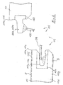
- Fig. 3 illustrated embodiment is a tongue and groove profile, which can be connected by interlocking two adjacent panels 10 and 10 'and 10 " Fig. 3 left Nutpaneel 10 lie flat on the ground, while the in Fig. 3 right spring panel 10 'or 10 "is fed laterally in an angled relative to the horizontal position until its spring 12b, 12d engages in the groove 12a, 12c of the panel 10.
- the two panels 10 and 10 'or 10 "provided by pivoting down the spring panel 10', 10" are engaged with each other in the illustrated embodiment, the locking means 14 are on the groove side 12a, 12c of the panel of a recess 14a formed in the upper surface of the lower, the groove 12 a, 12 c bounding lip 16.
- the Locking means 14 formed by a projection 14 b, which is provided on the underside of the spring 12 b, 12 d.
- the engagement of the coupling means 12 prevents a relative movement of the two panels 10 in the vertical direction H (see Fig. 1 ), that is, in a direction orthogonal to the panel plane or Begeh formation E of the panel 10 extending direction, while the interaction of the locking means 14 prevents relative movement of the two panels 10 in a panel plane E and orthogonal to the respective side edge 12a to 12d extending direction.
- the panel plane E is thereby spanned by the longitudinal direction L (direction of the long sides 10a and 10b) and the transverse direction Q (direction of the short sides 10c and 10d) of the panel 10.
- the panels 10 according to the invention additionally have a roughening 18, which at least complicates a relative movement of two interconnected panels 10 in the longitudinal direction of the respective side edge 10a / 10b, 10c / 10d.
- a roughening 18 which at least complicates a relative movement of two interconnected panels 10 in the longitudinal direction of the respective side edge 10a / 10b, 10c / 10d.
- at least one surface portion of the abutting surfaces of the coupling means 12 and the locking means 14 is provided with such a roughening 18.
- this is on the one hand the base 14a1 of the recess 14a of the in Fig. 3 Nutpaneels shown on the left and the top surface 14b1 of the projection 14b of in Fig. 3 right illustrated spring panel.
- the two aforementioned surfaces 14a1 and 14b1 abut against each other in the connected state of two adjacent panels, thus interacting with their respective roughnesses, thereby effectively increasing the longitudinal friction of the respective side edges 10a / 10b, 10c / 10d.
- the surface 14a1 and 14b1 of the panel 10 therefore form "complementary" surfaces.
- the roughenings 18 extend in the longitudinal direction of the two side edges preferably over its entire length while, as in Fig. 3 shown, are provided in the circumferential direction U only on a part of the boundary surface of the groove or the spring.
- the latter has mainly manufacturing reasons.
- the roughenings 18 are each formed by a toothing, the teeth 18a in the longitudinal direction of the respective side edge 10a / 10b, 10c / 10d successive (“tooth follower"), each individual tooth substantially in the circumferential direction U, ie orthogonal to the longitudinal direction of the respective side edge extends ("Zahnerstreckungsraum").
- the toothing 18, for example, by impressing the teeth 18a in the base 14a1 of the recess 14a and in the head surface 14b1 of the projection 14b are formed.
- a rotating tool 20 or 22 with the surfaces 14a1 and 14b1 is brought into engagement, the peripheral surface 20a and 22a has one of the teeth to be formed 18 corresponding counter-toothing.
- a further tool 24 is shown, which corresponds in construction and function of the tools 20 and 22, but is arranged such that it provides an oblique boundary surface 14a2 of the recess 14a with a toothing. It should also be noted that at the in Fig. 4 shown right spring panel no analog gear tool for the local inclined surface 14b2 is provided. Nevertheless, even the one-sided provision of a toothing can further increase the friction between the two panels.
- Fig. 5 and 6 a modified embodiment is shown, which essentially according to the embodiment Fig. 3 and 4 equivalent. Therefore, in the Fig. 5 and 6 Analog parts provided with the same reference numerals as in Fig. 3 and 4 , but increased by the number 100. In addition, the Fig. 5 and 6 in the following will be described only insofar as they differ from the above-described embodiment, the description of which is hereby expressly referred to.
- panel 110 differs from the panel 10 according to Fig. 3 and 4 on the one hand, that the coupling means 112 formed on the side edges 110a-110d are not formed so that two adjacent panels can be connected to each other by angling the spring panel into the groove panel, but the panels 110 are connected by a substantially planar telescoping parallel to the panel plane E. become.
- the locking means 114 are in this case formed by a projection 114a at the free end of the groove 112a, 112c limiting lower lip 116 and by a recess 114b in the region of the transition of the spring 112b, 112d in the panel 110.
- both the groove 112a, 112c and the spring 112b, 112d provided with a roughening 118, on the one hand to an upper boundary surface 116a of the lower lip 116 and the other to a lower boundary surface 122 of the spring 112b, 112d.
- the roughenings 118 are formed in the present case of particles 118a, which by means of a spray tool 128 or 130 (see Fig. 6 ) on the surfaces 116a and 126th can be applied, preferably using a primer that holds the particles 118a after it has dried on the surfaces 116a, 126.
- a solvent can also be applied to the surfaces 116a and 126, which at least solves a wood material used for forming the panels 110, for example solid wood, MDF or the like, so that individual wood fibers are at least partially made loosen the material composite and protrude from the surface after drying of the treatment agent.
- a wood material used for forming the panels 110 for example solid wood, MDF or the like
- Fig. 5 118a denotes the wood fibers protruding from the surfaces 116a and 126a.
- the panels 10, 110 can be made of any material, such as a wood material, such as solid wood boards, MDF boards, chipboard or the like, or even of compact laminate, plastic and the like suitable panel materials.
- a core 10e, 110e which is formed for example as MDF board (medium-density fiberboard), said core 10e, 110e at its footprint E a decorative layer 10f, 110f and its the loading side E opposite, lying on the bottom bottom B with a leveling layer 10g, 110g is glued.
- the decorative layer 10f, 110f may, for example, comprise one or more layers of printed paper impregnated with synthetic resin.
- the compensating layer 10g, 100g may also be formed by such a laminate layer comprising a plurality of paper layers.
- the groove 112a, 112c and the spring 112b, 112d need not necessarily be formed directly from the material of the core 110e. Rather, it is, as in Fig. 6 indicated by dashed lines, also possible to inject into a prepared in the side surface 110a to 110d recess 150 a suitable material, such as plastic, a wood extrudate or the like, and cure there and the groove 112a, 112c and the spring 112b, 112d thereafter to be trained by machining.
- a suitable material such as plastic, a wood extrudate or the like
Abstract
Description
Die Erfindung betrifft ein Verkleidungspaneel mit zwei Paaren von einander gegenüberliegenden Seitenrändern, wobei wenigstens ein Seitenränder-Paar mit Kopplungsmitteln versehen ist, welche im Wesentlichen in Form einer Nut und einer Feder ausgebildet sind und sich längs des jeweiligen Seitenrands erstrecken.The invention relates to a trim panel having two pairs of opposite side edges, wherein at least one side edge pair is provided with coupling means, which are formed substantially in the form of a groove and a spring and extending along the respective side edge.
Derartige Verkleidungspaneele sind allgemein bekannt. Beispielsweise sei auf die
Die gattungsgemäßen Paneele werden üblicherweise dadurch hergestellt, dass man im Wesentlichen quaderförmige Rohpaneele, d.h. Rohpaneele, deren den Seitenrändern zugeordnete Seitenflächen im Wesentlichen orthogonal zur Begehfläche verlaufen, spanabhebend bearbeitet, beispielsweise durch Fräsen, um an wenigstens einem der Seitenflächen-Paare die Kopplungsmittel herauszubilden, und zwar in Form einer Nut im Bereich der einen Seitenfläche sowie einer Feder im Bereich der anderen Seitenfläche. Ziel dieser spanabhebenden Bearbeitung ist es dabei stets, möglichst glatte Oberflächen zu erzielen, um beim Verlegen der Verkleidungspaneele zwei über Nut und Feder miteinander verbundene Paneele in Längsrichtung des betreffenden Seitenrands relativ zueinander verschieben zu können.The generic panels are usually made by substantially forming cuboidal panels, i. Raw panels whose side surfaces associated with the side edges substantially orthogonal to the loading surface, machined, for example by milling to form the coupling means on at least one of the side surface pairs, in the form of a groove in the region of a side surface and a spring in the region other side surface. The aim of this machining is always to achieve surfaces as smooth as possible in order to move when installing the cladding panels two interconnected via tongue and groove panels in the longitudinal direction of the respective side edge relative to each other.
Ein Problem, mit welchem gattungsgemäße Verkleidungspaneele in der Praxis stets zu kämpfen haben, sind die jahreszeitlich bedingten Schwankungen der relativen Luftfeuchtigkeit. Während Zeiten hoher relativer Luftfeuchtigkeit dehnen sich die Verkleidungspaneele aufgrund von Quellung aus, während sie aufgrund der niedrigeren relativen Luftfeuchtigkeit während der Heizungsperiode im Winter schrumpfen. Dieses Quellen und Schrumpfen führt selbst dann zur Bildung von Spalten zwischen aneinander angrenzenden Paneelen, wenn die Kopplungsmittel der Verkleidungspaneele, wie dies bei vielen derzeit auf dem Markt erhältlichen Typen von Verkleidungspaneelen üblich ist, mit integrierten Verriegelungsmitteln ausgebildet sind, welche sich in Längsrichtung des jeweiligen Seitenrands des Verkleidungspaneels erstrecken und einer Relativbewegung der beiden Paneele in einer in der Paneelebene und orthogonal zum jeweiligen Seitenrand verlaufenden Richtung versuchen entgegenzuwirken. Als weitere Ursachen für die Bildung von Spalten sind die einwirkungen von statischen und mechanisch-dynamischen Belastungen zu nennen, wie sie auf den Boden beispielsweise von schweren Einrichtungsgegenständen oder durch dessen Begehen ausgeübt werden. Bei rechteckigen Verkleidungspaneelen zeigt sich dieses Spaltenbildungsproblem insbesondere an den Kurzseiten der Paneele. Besonders stark tritt das Spaltenbildungsproblem zudem dann auf, wenn die Paneele, wie heutzutage üblich, auf dem Untergrund frei schwimmend verlegt sind, d.h. mit dem Untergrund nicht durch gesonderte Verbindungsmittel verbunden sind, und nicht miteinander verklebt sind.A problem with which generic trim panels always have to contend in practice, are the seasonal variations in relative humidity. During periods of high relative humidity, the trim panels expand due to swelling while shrinking due to lower relative humidity during the heating period in winter. This swelling and shrinking leads to the formation of gaps between adjacent panels, even if the coupling means of the cladding panels, as is common in many types of trim panels currently available on the market, are formed with integral locking means which extend longitudinally of the respective side edge of the trim panel and attempt relative movement of the two panels in a direction in the panel plane and orthogonal to the respective side edge counteract. Other causes for the formation of cracks include the effects of static and mechanical-dynamic loads, such as those that are exerted on the ground, for example, by heavy furnishings or by their conquest. For rectangular cladding panels, this cleavage problem is particularly evident on the short sides of the panels. The splitting problem also occurs particularly strongly when the panels, as usual today, are laid freely floating on the ground, ie are not connected to the ground by separate connecting means and are not glued together.
Zur Verhinderung von Spaltenbildung wurde in der
Es ist daher Aufgabe der vorliegenden Erfindung, ein Verkleidungspaneel der eingangs genannten Art bereitzustellen, bei welchem der Bildung von Spalten zwischen zwei miteinander verbundenen Paneelen unter Verzicht auf das Vorsehen einer derartigen Vorspannkraft entgegengewirkt werden kann.It is therefore an object of the present invention to provide a trim panel of the type mentioned, in which the formation of gaps between two interconnected panels waiving the provision of such biasing force can be counteracted.
Diese Aufgabe wird erfindungsgemäß durch ein Verkleidungspaneel der eingangs genannten Art gelöst, bei welchem wenigstens ein Abschnitt der Begrenzungsfläche der Nut oder/und wenigstens ein Abschnitt der Begrenzungsfläche der Feder mit einer Aufrauhung versehen ist.This object is achieved by a trim panel of solved at the beginning, at least a portion of the boundary surface of the groove and / or at least a portion of the boundary surface of the spring is provided with a roughening.
Unter der "Begrenzungsfläche" wird dabei im Zusammenhang mit der vorliegenden Erfindung diejenige Fläche verstanden, die von der Seitenfläche des jeweiligen Seitenrands ausgeht, die Nut mit einer in die Nut hinein weisenden Flächennormalen bzw. die Feder mit einer von der Feder weg weisenden Flächennormalen umläuft und auf der anderen Seite der Nut bzw. der Feder wieder an der Seitenfläche des Seitenrands endet.In the context of the present invention, the "boundary surface" is understood to be that surface which starts from the side surface of the respective side edge, the groove rotates with a surface normal pointing into the groove, or the spring revolves with a surface normal pointing away from the spring, and on the other side of the groove or the spring ends again on the side surface of the side edge.
Durch das Vorsehen der erfindungsgemäßen Aufrauhung wird die Reibung zwischen der Nut des einen Paneels und der Feder des anderen Paneels erhöht, sodass eine Relativverlagerung der beiden miteinander verbundenen Paneele in Längsrichtung der Nut bzw. der Feder erschwert ist. Hierdurch wird auch der Spaltbildung an der orthogonal zu dieser Längsrichtung verlaufenden Paneelseite entgegengewirkt. D.h. dann, wenn das Verkleidungspaneel ein rechteckiges Verkleidungspaneel mit einer Kurzseite und einer Langseite ist, kann der Spaltenbildung an der Kurzseite des Paneels dadurch entgegengewirkt werden, dass man zumindest an der Langseite wenigstens einen Abschnitt der Begrenzungsfläche von Nut oder/und Feder mit einer Aufrauhung versieht. Selbstverständlich hat auch das Vorsehen einer Aufrauhung im Bereich der Nut oder/und der Feder der Kurzseite des Paneels eine Minderung der Neigung zur Spaltenbildung an der Langseite des Paneels zur Folge.By providing the roughening according to the invention, the friction between the groove of one panel and the spring of the other panel is increased, so that a relative displacement of the two interconnected panels in the longitudinal direction of the groove or the spring is difficult. As a result, the gap formation is counteracted at the panel side extending orthogonally to this longitudinal direction. That when the trim panel is a rectangular trim panel with a short side and a long side, the formation of gaps on the short side of the panel can be counteracted by roughening at least on the long side at least a portion of the groove or tongue and groove boundary surface. Of course, the provision of a roughening in the region of the groove or / and the spring of the short side of the panel has a reduction in the tendency to form crevices on the long side of the panel.
Im Hinblick auf die Erzielung einer möglichst hohen Reibung ist es bevorzugt, wenn sich der mit der Aufrauhung versehene wenigstens eine Abschnitt der Begrenzungsfläche sowohl über die im Wesentlichen gesamte Länge des jeweiligen Seitenrands als auch in Umfangsrichtung der Begrenzungsfläche über den im Wesentlichen gesamten Umfang der Begrenzungsfläche erstreckt. Nicht zuletzt aus fertigungstechnischen Gründen kann es jedoch auch wünschenswert sein, dass der mit der Aufrauhung versehene wenigstens eine Abschnitt der Begrenzungsfläche sich lediglich über einen Teil der Länge des jeweiligen Seitenrands oder/und in Umfangsrichtung lediglich über einen Teil der Begrenzungsfläche erstreckt.With regard to achieving the highest possible friction, it is preferred if the at least one section of the boundary surface provided with the roughening extends over substantially the entire length of the respective side edge and also in the circumferential direction of the boundary surface over the substantially entire circumference of the boundary surface , Not least for manufacturing reasons, however, it may also be desirable that the provided with the roughening at least a portion of the boundary surface extends only over part of the length of the respective side edge and / or in the circumferential direction only over part of the boundary surface.
Die Reibung zwischen der Begrenzungsfläche der Nut und der korrespondierenden Begrenzungsfläche der Feder kann weiter dadurch erhöht werden, dass dann, wenn sowohl wenigstens ein Abschnitt der Begrenzungsfläche der Nut als auch wenigstens ein Abschnitt der Begrenzungsfläche der Feder mit einer Aufrauhung versehen sind, diese Aufrauhungen wenigstens zum Teil an zueinander komplementären Abschnitten der Begrenzungsflächen von Nut und Feder vorgesehen sind. Als "komplementär" im Sinne dieses Anspruchs sind zwei Abschnitte der Begrenzungsflächen von Nut bzw. Feder ein und desselben Paneels dann anzusehen, wenn bei Verbindung zweier identischer Paneele der mit einer Aufrauhung versehene Abschnitt der Nut des einen Paneels und der mit einer Aufrauhung versehene Abschnitt der Feder des anderen Paneels im verbundenen Zustand dieser beiden Paneele aneinander anliegen.The friction between the boundary surface of the groove and the corresponding boundary surface of the spring can be further increased by providing at least a portion of the boundary surface of the groove and at least a portion of the boundary surface of the spring with a roughening Part are provided on mutually complementary portions of the boundary surfaces of tongue and groove. As a "complementary" in the sense of this claim, two sections of the boundary surfaces of tongue or groove one and the same panel are to be considered if, when connecting two identical panels provided with a roughening portion of the groove of a panel and provided with a roughening section of Spring of the other panel in the connected state of these two panels abut each other.
Beispielsweise kann wenigstens ein mit einer Aufrauhung versehener Abschnitt von einer Verzahnung gebildet sein. Zur Erzielung einer möglichst hohen Reibung zwischen zwei miteinander verbundenen Paneelen wird dabei vorgeschlagen, dass die Zahnfolgerichtung der Verzahnung im Wesentlichen in Längsrichtung des jeweiligen Seitenrands verläuft, während die Zahnerstreckungsrichtung im Wesentlichen in Umfangsrichtung der Nut bzw. der Feder verläuft. Unter der "Zahnfolgerichtung" wird dabei diejenige Richtung verstanden, in welcher die Zähne der Verzahnung aufeinander folgen; bei einem herkömmlichen Zahnrad also die Umfangsrichtung des Zahnrads. Als "Zahnerstreckungsrichtung" wird hingegen diejenige Richtung verstanden, in der sich der einzelne Zahn erstreckt; bei einem herkömmlichen Zahnrad mit Geradverzahnung also die Achsrichtung.For example, at least one section provided with a roughening can be formed by a toothing. In order to achieve the highest possible friction between two interconnected panels, it is proposed that the tooth follower direction of the toothing extends substantially in the longitudinal direction of the respective side edge, while the tooth extension direction extends substantially in the circumferential direction of the groove or spring. The "tooth following direction" is understood to be that direction in which the teeth of the toothing follow one another; in a conventional gear so the circumferential direction of the gear. By contrast, the term "tooth extension direction" is understood to mean that direction in which the individual tooth extends; in a conventional spur gear so the axial direction.
Die Verzahnung kann beispielsweise durch eine im Wesentlichen spanlose Bearbeitung gebildet sein, etwa durch Eindrücken, Einkerben oder dergleichen. Zusätzlich oder alternativ ist es jedoch auch möglich, dass die Verzahnung durch eine spanende Bearbeitung zu bilden, beispielsweise durch Stechen, Fräsen oder dergleichen. In beiden Alternativen zur Herstellung der Verzahnung ist es jedoch vorteilhaft, ein Werkzeug einzusetzen, dessen Rotationsgeschwindigkeit derart auf die Vorschubgeschwindigkeit des Paneels abgestimmt ist, dass seine Umfangsgeschwindigkeit im Wesentlichen mit der Vorschubgeschwindigkeit des Paneels übereinstimmt.The toothing can be formed for example by a substantially non-cutting machining, such as by impressions, notching or the like. Additionally or alternatively, however, it is also possible for the teeth to be formed by machining, for example by piercing, milling or the like. In both alternatives for producing the toothing, however, it is advantageous to use a tool whose rotational speed is matched to the feed rate of the panel, that its peripheral speed substantially coincides with the feed rate of the panel.
In einer zweiten Ausführungsvariante, die zusätzlich oder alternativ zur Ausbildung des aufgerauhten Abschnitts als Verzahnung eingesetzt werden kann, kann wenigstens ein mit einer Aufrauhung versehener Abschnitt von einer Mehrzahl von Holzfasern gebildet sein, welche aus der Oberfläche des jeweiligen Abschnitts der Begrenzungsfläche hervorstehen. Um dieses Aufstellen der Fasern zu erreichen, kann die Oberfläche mit einem Mittel behandelt sein, beispielsweise mit einem wasserverdünnbaren Lack (wie einer weichmacherfreien wässrigen Copolymerisatdispersion), welches die Fasern zumindest teilweise aus ihrem Materialverbund, beispielsweise Vollholz, MDF oder einem anderen Holzwerkstoff, herauslöst, aufstellt und fixiert.In a second variant, which can be used in addition to or alternatively to the formation of the roughened portion as a toothing, at least one provided with a roughening portion of a plurality of wood fibers may be formed, which protrude from the surface of the respective portion of the boundary surface. In order to achieve this setting up of the fibers, the surface may be treated with an agent, for example with a water-dilutable paint (such as a plasticizer-free aqueous copolymer dispersion) which at least partially removes the fibers from their composite material, for example solid wood, MDF or another wood-based material, sets up and fixes.
Gemäß einer dritten Ausführungsvariante, die wiederum zusätzlich oder alternativ zu den beiden vorstehend erläuterten Ausführungsvarianten zum Einsatz kommen kann, kann wenigstens ein mit einer Aufrauhung versehener Abschnitt von einer Mehrzahl von Partikeln gebildet sein, welche auf die Oberfläche des jeweiligen Abschnitts der Begrenzungsfläche aufgebracht sind. Als diese Partikel kommen beispielsweise Partikel aus mikronisiertem Polypropylenwachs in Betracht, welche eine Größe von zwischen etwa 30 µm und 75 µm aufweisen. Ferner können diese Partikel mittels eines Haftvermittlers, beispielsweise einem wasserverdünnbaren Lack (etwa einer weichmacherfreien wässrigen Copolymerisatdispersion) mit der Oberfläche des jeweiligen Abschnitts der Begrenzungsfläche verbunden sein.According to a third embodiment, which in turn may be used in addition to or as an alternative to the two embodiments described above, at least one section provided with a roughening can be formed by a plurality of particles which are applied to the surface of the respective section of the boundary surface. As these particles are, for example, particles of micronized polypropylene wax into consideration, which have a size of between about 30 microns and 75 microns. Furthermore, these particles can be bonded to the surface by means of an adhesion promoter, for example a water-dilutable paint (for example a plasticizer-free aqueous copolymer dispersion) be connected to the respective portion of the boundary surface.
Wie vorstehend bereits angedeutet, kann zumindest ein Kern des Paneels aus einem Holzwerkstoff, beispielsweise Vollholz, einer Spanplatte, einer MDF-Platte oder dergleichen, gebildet sein. Grundsätzlich ist es jedoch auch möglich, die erfindungsgemäßen Prinzipien bei anderen Werkstoffen einzusetzen, beispielsweise Kompaktlaminat, Kunststoff oder dergleichen.As already indicated above, at least one core of the panel can be formed from a wood material, for example solid wood, a chipboard, an MDF board or the like. In principle, however, it is also possible to use the principles according to the invention for other materials, for example compact laminate, plastic or the like.
Wie vorstehend ebenfalls bereits erwähnt, können die Kopplungsmittel mit integrierten Verriegelungsmitteln ausgebildet sein, welche sich in Längsrichtung des jeweiligen Seitenrands erstrecken. Diese Verriegelungsmittel können dabei beispielsweise einstückig aus dem Kernmaterial gebildet sein. Grundsätzlich ist es jedoch auch denkbar, die Verriegelungsmittel oder/und die Kopplungsmittel in bzw. an einer mit dem Kern des Paneels verbundenen Kopplungseinheit auszubilden. Diese Kopplungseinheit kann beispielsweise dadurch mit dem Kern des Paneels verbunden sein, dass man ein geeignetes Material, beispielsweise Kunststoff, ein Holzextrudat oder dergleichen, in eine vorbereitete Vertiefung in der Seitenfläche des Paneels einspritzt und anschließend zur Bildung der Kopplungsmittel oder/und der Verriegelungsmittel materialabtragend bearbeitet. Alternativ ist es jedoch auch möglich, ein vorgefertigtes Teil mit daran vorgefertigten Kopplungsmitteln oder/und Verriegelungsmitteln in die vorbereitete Vertiefung einzulegen.As already mentioned above, the coupling means may be formed with integrated locking means which extend in the longitudinal direction of the respective side edge. This locking means can be formed, for example, in one piece from the core material. In principle, however, it is also conceivable to form the locking means and / or the coupling means in or on a coupling unit connected to the core of the panel. This coupling unit can for example be connected to the core of the panel by injecting a suitable material, for example plastic, a wood extrudate or the like, into a prepared recess in the side surface of the panel and subsequently machining it to form the coupling means and / or the locking means , Alternatively, however, it is also possible to insert a prefabricated part with prefabricated coupling means and / or locking means in the prepared recess.
In besonders vorteilhafter Weise kann die Erfindung dann eingesetzt werden, wenn das Verkleidungspaneel ein Fußbodenpaneel ist, und zwar insbesondere dann, wenn das Fußbodenpaneel zur schwimmenden Verlegung oder/und zu Verlegung ohne die Verwendung von Klebstoff zur Verbindung benachbarter Paneele bestimmt ist.In a particularly advantageous manner, the invention can be used when the trim panel is a floor panel, especially if the floor panel is intended for floating installation and / or laying without the use of adhesive to connect adjacent panels.
Die Erfindung wird im Folgenden an Ausführungsbeispielen anhand der beigefügten Zeichnungen näher erläutert werden. Es stellt dar:
- Fig. 1
- eine Draufsicht auf ein erfindungsgemäßes Verkleidungspaneel;
- Fig. 2
- eine Teildraufsicht auf einen aus einer Mehrzahl derartiger Verkleidungspaneele gebildeten Verkleidungsbelag;
- Fig. 3
- eine perspektivische Darstellung des Nutendes und des Federendes eines erfindungsgemäß mit einer Aufrauhung versehenen Verkleidungspaneels;
- Fig. 4
- eine schematische Seitenansicht des Paneels gemäß
Fig. 3 zur Erläuterung des Verfahrens zur Ausbildung der Aufrauhung; und - Fig. 5 und 6
- Ansichten ähnlich
Fig. 3 und4 einer weiteren Ausführungsform eines erfindungsgemäßen Verkleidungspaneels.
- Fig. 1
- a plan view of an inventive panel panel;
- Fig. 2
- a partial plan view of a formed from a plurality of such panel panels lining covering;
- Fig. 3
- a perspective view of the groove end and the spring end of a present invention provided with a roughening panel panel;
- Fig. 4
- a schematic side view of the panel according to
Fig. 3 to explain the method of forming the roughening; and - FIGS. 5 and 6
- Similar views
Fig. 3 and4 a further embodiment of a trim panel according to the invention.
In
Die Kopplungsmittel 12 sind im Wesentlichen in Form einer an der Langseite 10a vorgesehenen Nut 12a und einer an der Langseite 10b vorgesehenen Feder 12b gebildet, die zusammen die Kopplungsmittel der Langseite bilden, sowie einer an der Kurzseite 10c vorgesehen Nut 12c und einer an der Kurzseite 10d vorgesehenen Feder 12d, die zusammen die Kopplungsmittel der Kurzseite bilden. Diese Kopplungsmittel 12 können in verschiedenen Varianten ausgeführt sein, von denen mit Bezug auf die
Die Darstellung gemäß
Bei der in
Im verbundenen Zustand zweier Paneele 10 verhindert der Eingriff der Kopplungsmittel 12 eine Relativbewegung der beiden Paneele 10 in Hochrichtung H (siehe
Im Unterschied zu den Paneelen des Standes der Technik verfügen die erfindungsgemäßen Paneele 10 zusätzlich über eine Aufrauhung 18, welche eine Relativbewegung zweier miteinander verbundener Paneele 10 in Längsrichtung des jeweiligen Seitenrands 10a/10b, 10c/10d zumindest erschwert. Hierzu ist wenigstens ein Flächenabschnitt der aneinander anliegenden Oberflächen der Kopplungsmittel 12 und der Verriegelungsmittel 14 mit einer derartigen Aufrauhung 18 versehen. In dem in
Die Aufrauhungen 18 erstrecken sich in Längsrichtung der beiden Seitenränder vorzugsweise über deren gesamte Länge, während sie, wie in
Wie in
Wie in
In
In den
Das in den
Auch in dem in den
Festzuhalten ist noch, dass es grundsätzlich auch denkbar ist, lediglich eine der beiden komplementären Flächen 116a, 126 mit solchen aufgesprühten Partikeln zu versehen, um eine höhere Reibung zwischen den beiden Paneelen 110 zu erreichen. Darüber hinaus ist es denkbar, derartige Partikel auch auf die in
Anhand der schematischen Darstellungen gemäß
Und zwar kann mittels der Sprühwerkzeuge 128 und 130 auch ein Lösungsmittel auf die Flächen 116a und 126 aufgebracht werden, welches einen zur Bildung der Paneele 110 verwendeten Holzwerkstoff, beispielsweise Vollholz, MDF oder dergleichen, zumindest so weit anlöst, dass sich einzelne Holzfasern zumindest teilweise aus dem Werkstoffverbund lösen und nach dem Abtrocknen des Behandlungsmittels aus der Oberfläche hervorstehen. In diesem Fall sind in
Nachzutragen ist noch Folgendes:Add to this is the following:
Die Paneele 10, 110 können aus einem beliebigen Werkstoff gefertigt sein, beispielsweise einem Holzwerkstoff, wie beispielsweise Vollholzbrettern, MDF-Platten, Spanplatten oder dergleichen, oder aber auch aus Kompaktlaminat, Kunststoff und dergleichen geeigneten Paneelmaterialien.The
Falls die Paneele als Fußbodenpaneele eingesetzt werden sollen, können sie, wie in
Die Nut 112a, 112c bzw. die Feder 112b, 112d brauchen nicht notwendigerweise unmittelbar aus dem Material des Kerns 110e gebildet zu sein. Vielmehr ist es, wie in
Claims (11)
dadurch gekennzeichnet, dass die Aufrauhung (118) in Form einer Mehrzahl von zumindest teilweise aus dem Materialverbund des Verkleidungspaneels herausgelösten Holzfasern (118a) gebildet ist, welche aus der Oberfläche des jeweiligen Abschnittes der Begrenzungsfläche hervorstehen.A trim panel (110) having two pairs of opposed side edges (110a-110d), at least one side edge pair being provided with coupling means (112) substantially in the form of a groove (112a, 112c) and a spring (112b, 112d ) and extending along the respective side edge, wherein at least a portion (116a) of the boundary surface of the groove (112a, 112c) and / or at least a portion (126) of the boundary surface of the spring (112b, 112d) with a roughening (118 ),
characterized in that the roughening (118) in the form of a plurality of at least partially out of the composite material of the cladding panel wood fibers (118a) is formed, which protrude from the surface of the respective portion of the boundary surface.
dadurch gekennzeichnet, dass dann, wenn es ein rechteckiges Verkleidungspaneel mit einer Kurzseite (10c, 10d) und einer Langseite (10a, 10b) ist, zumindest an der Langseite (10a, 10b) wenigstens ein Abschnitt (14a1, 14b1) der Begrenzungsfläche von Nut oder/und Feder mit einer Aufrauhung (18) versehen ist.Cladding panel according to claim 1,
characterized in that , if it is a rectangular fairing panel with a short side (10c, 10d) and a long side (10a, 10b) at least on the long side (10a, 10b) at least a portion (14a1, 14b1) of the boundary surface of groove or / and spring is provided with a roughening (18).
dadurch gekennzeichnet, dass sich der mit der Aufrauhung (18) versehene wenigstens eine Abschnitt (14a1, 14b1) der Begrenzungsfläche lediglich über einen Teil der Länge des jeweiligen Seitenrands erstreckt.Cladding panel according to claim 1 or 2,
characterized in that the at least one portion (14a1, 14b1) of the boundary surface provided with the roughening (18) extends only over part of the length of the respective side edge.
dadurch gekennzeichnet, dass sich der mit der Aufrauhung (18) versehene wenigstens eine Abschnitt (14a1, 14b1) der Begrenzungsfläche über die im Wesentlichen gesamte Länge des jeweiligen Seitenrands erstreckt.Cladding panel according to claim 1 or 2,
characterized in that the roughening (18) provided at least a portion (14a1, 14b1) of the boundary surface extends over the substantially entire length of the respective side edge.
dadurch gekennzeichnet, dass sich der mit der Aufrauhung (18) versehene wenigstens eine Abschnitt (14a1, 14b1) der Begrenzungsfläche in Umfangsrichtung (U) der Begrenzungsfläche lediglich über einen Teil des Umfangs der Begrenzungsfläche erstreckt.Cladding panel according to one of claims 1 to 4,
characterized in that the at least one portion (14a1, 14b1) of the boundary surface provided with the roughening (18) extends in the circumferential direction (U) of the boundary surface only over a part of the circumference of the boundary surface.
dadurch gekennzeichnet, dass sich der mit der Aufrauhung (18) versehene wenigstens eine Abschnitt (14a1, 14b1) der Begrenzungsfläche in Umfangsrichtung (U) der Begrenzungsfläche über den im Wesentlichen gesamten Umfang der Begrenzungsfläche erstreckt.Cladding panel according to one of claims 1 to 4,
characterized in that the at least one portion (14a1, 14b1) of the boundary surface provided with the roughening (18) extends in the circumferential direction (U) of the boundary surface over the substantially entire circumference of the boundary surface.
dadurch gekennzeichnet, dass zumindest ein Kern (10e) des Paneels (10) aus einem Holzwerkstoff, beispielsweise Vollholz, einer Spanplatte, einer MDF-Platte oder dergleichen, oder/und aus Kompaktlaminat oder/und aus Kunststoff gefertigt ist.Cladding panel according to one of claims 1 to 6,
characterized in that at least one core (10e) of the panel (10) is made of a wood material, for example solid wood, a chipboard, an MDF board or the like, and / or of compact laminate and / or of plastic.
dadurch gekennzeichnet, dass die Kopplungsmittel (12) mit integrierten Verriegelungsmitteln (14) ausgebildet sind, welche sich in Längsrichtung (L bzw. Q) des jeweiligen Seitenrands (10a-10d) erstrecken.Cladding panel according to one of claims 1 to 7,
characterized in that the coupling means (12) are formed with integrated locking means (14) extending in the longitudinal direction (L or Q) of the respective side edge (10a-10d).
dadurch gekennzeichnet, dass die Verriegelungsmittel (14) einstückig aus dem Material des Kerns (10e) gefertigt sind.Cladding panel according to claim 8,
characterized in that the locking means (14) are made in one piece from the material of the core (10e).
dadurch gekennzeichnet, dass die Kopplungsmittel (112) oder/und die Verriegelungsmittel (114) in bzw. an einer mit dem Kern (110e) des Paneels (110) verbundenen Kopplungseinheit (150) ausgebildet sind.Cladding panel according to one of claims 1 to 9,
characterized in that the coupling means (112) and / or the locking means (114) are formed in or on a coupling unit (150) connected to the core (110e) of the panel (110).
dadurch gekennzeichnet, dass es ein Fussbodenpaneel ist.Cladding panel according to one of claims 1 to 10,
characterized in that it is a floor panel.
Applications Claiming Priority (2)
| Application Number | Priority Date | Filing Date | Title |
|---|---|---|---|
| DE102004054368A DE102004054368A1 (en) | 2004-11-10 | 2004-11-10 | trim panel |
| EP05802289A EP1809833B1 (en) | 2004-11-10 | 2005-11-09 | Covering panel |
Related Parent Applications (1)
| Application Number | Title | Priority Date | Filing Date |
|---|---|---|---|
| EP05802289A Division EP1809833B1 (en) | 2004-11-10 | 2005-11-09 | Covering panel |
Publications (1)
| Publication Number | Publication Date |
|---|---|
| EP2085534A1 true EP2085534A1 (en) | 2009-08-05 |
Family
ID=35515658
Family Applications (2)
| Application Number | Title | Priority Date | Filing Date |
|---|---|---|---|
| EP05802289A Active EP1809833B1 (en) | 2004-11-10 | 2005-11-09 | Covering panel |
| EP09160400A Withdrawn EP2085534A1 (en) | 2004-11-10 | 2005-11-09 | Covering panel |
Family Applications Before (1)
| Application Number | Title | Priority Date | Filing Date |
|---|---|---|---|
| EP05802289A Active EP1809833B1 (en) | 2004-11-10 | 2005-11-09 | Covering panel |
Country Status (18)
| Country | Link |
|---|---|
| US (1) | US8001741B2 (en) |
| EP (2) | EP1809833B1 (en) |
| JP (1) | JP5122971B2 (en) |
| CN (2) | CN100575638C (en) |
| AT (1) | ATE440189T1 (en) |
| AU (1) | AU2005303947B2 (en) |
| CA (1) | CA2586186C (en) |
| DE (2) | DE102004054368A1 (en) |
| DK (1) | DK1809833T3 (en) |
| ES (1) | ES2329267T3 (en) |
| HR (1) | HRP20090476T1 (en) |
| MX (1) | MX2007005540A (en) |
| PL (1) | PL1809833T3 (en) |
| PT (1) | PT1809833E (en) |
| RU (1) | RU2358073C2 (en) |
| SI (1) | SI1809833T1 (en) |
| UA (1) | UA88490C2 (en) |
| WO (1) | WO2006050928A1 (en) |
Families Citing this family (69)
| Publication number | Priority date | Publication date | Assignee | Title |
|---|---|---|---|---|
| US20020178674A1 (en) | 1993-05-10 | 2002-12-05 | Tony Pervan | System for joining a building board |
| SE517183C2 (en) | 2000-01-24 | 2002-04-23 | Valinge Aluminium Ab | Locking system for mechanical joining of floorboards, floorboard provided with the locking system and method for making such floorboards |
| SE518184C2 (en) | 2000-03-31 | 2002-09-03 | Perstorp Flooring Ab | Floor covering material comprising disc-shaped floor elements which are joined together by means of interconnecting means |
| US20040211144A1 (en) * | 2001-06-27 | 2004-10-28 | Stanchfield Oliver O. | Flooring panel or wall panel and use thereof |
| US8028486B2 (en) | 2001-07-27 | 2011-10-04 | Valinge Innovation Ab | Floor panel with sealing means |
| SE525661C2 (en) | 2002-03-20 | 2005-03-29 | Vaelinge Innovation Ab | Floor boards decorative joint portion making system, has surface layer with underlying layer such that adjoining edge with surface has underlying layer parallel to horizontal plane |
| BRPI0308966B8 (en) | 2002-04-03 | 2016-05-17 | Vaelinge Innovation Ab | floor board |
| SE525657C2 (en) | 2002-04-08 | 2005-03-29 | Vaelinge Innovation Ab | Flooring boards for floating floors made of at least two different layers of material and semi-finished products for the manufacture of floorboards |
| US8850769B2 (en) | 2002-04-15 | 2014-10-07 | Valinge Innovation Ab | Floorboards for floating floors |
| US8375673B2 (en) * | 2002-08-26 | 2013-02-19 | John M. Evjen | Method and apparatus for interconnecting paneling |
| US7845140B2 (en) | 2003-03-06 | 2010-12-07 | Valinge Innovation Ab | Flooring and method for installation and manufacturing thereof |
| US7677001B2 (en) | 2003-03-06 | 2010-03-16 | Valinge Innovation Ab | Flooring systems and methods for installation |
| US7886497B2 (en) | 2003-12-02 | 2011-02-15 | Valinge Innovation Ab | Floorboard, system and method for forming a flooring, and a flooring formed thereof |
| US20050166516A1 (en) | 2004-01-13 | 2005-08-04 | Valinge Aluminium Ab | Floor covering and locking systems |
| SE527570C2 (en) | 2004-10-05 | 2006-04-11 | Vaelinge Innovation Ab | Device and method for surface treatment of sheet-shaped material and floor board |
| US7841144B2 (en) | 2005-03-30 | 2010-11-30 | Valinge Innovation Ab | Mechanical locking system for panels and method of installing same |
| US8215078B2 (en) | 2005-02-15 | 2012-07-10 | Välinge Innovation Belgium BVBA | Building panel with compressed edges and method of making same |
| US8061104B2 (en) | 2005-05-20 | 2011-11-22 | Valinge Innovation Ab | Mechanical locking system for floor panels |
| SE533410C2 (en) | 2006-07-11 | 2010-09-14 | Vaelinge Innovation Ab | Floor panels with mechanical locking systems with a flexible and slidable tongue as well as heavy therefore |
| US7861482B2 (en) | 2006-07-14 | 2011-01-04 | Valinge Innovation Ab | Locking system comprising a combination lock for panels |
| DE102006051840A1 (en) * | 2006-08-09 | 2008-02-14 | Agepan-Tarkett Laminatepark Eiweiler Gmbh & Co. Kg | Attachment system for tabular panels |
| DE102006052081A1 (en) * | 2006-11-04 | 2008-05-08 | Agepan-Tarkett Laminatepark Eiweiler Gmbh & Co. Kg | Attachment system for tabular panels |
| EP3540146B1 (en) * | 2006-11-15 | 2021-08-25 | Välinge Innovation AB | Mechanical locking of floor panels with vertical folding |
| US11725394B2 (en) | 2006-11-15 | 2023-08-15 | Välinge Innovation AB | Mechanical locking of floor panels with vertical folding |
| SE532607C2 (en) * | 2006-11-15 | 2010-03-02 | Vaelinge Innovation Ab | Mechanical locking of vertical paneling floor panels |
| US8689512B2 (en) | 2006-11-15 | 2014-04-08 | Valinge Innovation Ab | Mechanical locking of floor panels with vertical folding |
| SE531111C2 (en) | 2006-12-08 | 2008-12-23 | Vaelinge Innovation Ab | Mechanical locking of floor panels |
| US8499521B2 (en) | 2007-11-07 | 2013-08-06 | Valinge Innovation Ab | Mechanical locking of floor panels with vertical snap folding and an installation method to connect such panels |
| US8353140B2 (en) * | 2007-11-07 | 2013-01-15 | Valinge Innovation Ab | Mechanical locking of floor panels with vertical snap folding |
| MY152779A (en) | 2008-01-31 | 2014-11-28 | Valinge Innovation Ab | Mechanical locking of floor panels, methods to install and uninstall panels, a method and an equipment to produce the locking system, a method to connect a displaceable tongue to a panel and a tongue blank |
| US8505257B2 (en) * | 2008-01-31 | 2013-08-13 | Valinge Innovation Ab | Mechanical locking of floor panels |
| CN102066674B (en) | 2008-05-15 | 2015-06-03 | 瓦林格创新股份有限公司 | Floor panels with a mechanical locking system activated by a magnetic field and a method to install the panels |
| DE202008010555U1 (en) * | 2008-08-08 | 2009-12-17 | Akzenta Paneele + Profile Gmbh | Plastic panel with hook profile |
| US20100068451A1 (en) * | 2008-09-17 | 2010-03-18 | David Richard Graf | Building panel with wood facing layer and composite substrate backing layer |
| WO2010087752A1 (en) | 2009-01-30 | 2010-08-05 | Välinge Innovation Belgium BVBA | Mechanical lockings of floor panels and a tongue blank |
| PL2524093T3 (en) | 2010-01-12 | 2020-07-27 | Välinge Innovation AB | Mechanical locking system for floor panels |
| US8234830B2 (en) | 2010-02-04 | 2012-08-07 | Välinge Innovations AB | Mechanical locking system for floor panels |
| BR112012018285B1 (en) | 2010-02-04 | 2020-02-18 | Välinge Innovation AB | SET OF FLOOR PANELS |
| DE212010000195U1 (en) | 2010-04-15 | 2012-08-06 | Spanolux N.V. Div. Balterio | Bottom plate arrangement |
| US20120024347A1 (en) * | 2010-07-27 | 2012-02-02 | Tzy-Ying Lin | Solar package structure and method for fabricating the same |
| UA109938C2 (en) | 2011-05-06 | 2015-10-26 | MECHANICAL LOCKING SYSTEM FOR CONSTRUCTION PANELS | |
| UA114715C2 (en) | 2011-07-05 | 2017-07-25 | Сералок Інновейшн Аб | Mechanical locking of floor panels with a glued tongue |
| US9725912B2 (en) * | 2011-07-11 | 2017-08-08 | Ceraloc Innovation Ab | Mechanical locking system for floor panels |
| US8650826B2 (en) | 2011-07-19 | 2014-02-18 | Valinge Flooring Technology Ab | Mechanical locking system for floor panels |
| DE102012102339A1 (en) * | 2011-07-29 | 2013-01-31 | Hamberger Industriewerke Gmbh | Connection for elastic or plate-shaped components, profile slides and floor coverings |
| US8763340B2 (en) | 2011-08-15 | 2014-07-01 | Valinge Flooring Technology Ab | Mechanical locking system for floor panels |
| US8857126B2 (en) | 2011-08-15 | 2014-10-14 | Valinge Flooring Technology Ab | Mechanical locking system for floor panels |
| US8769905B2 (en) | 2011-08-15 | 2014-07-08 | Valinge Flooring Technology Ab | Mechanical locking system for floor panels |
| CN102373785A (en) * | 2011-10-20 | 2012-03-14 | 宣建民 | Floor lock catch |
| US9216541B2 (en) | 2012-04-04 | 2015-12-22 | Valinge Innovation Ab | Method for producing a mechanical locking system for building panels |
| US8596013B2 (en) | 2012-04-04 | 2013-12-03 | Valinge Innovation Ab | Building panel with a mechanical locking system |
| US20140318895A1 (en) * | 2013-04-29 | 2014-10-30 | John Birk | Adjustable length scaffolding and method therefor |
| US20130313046A1 (en) * | 2012-05-24 | 2013-11-28 | John Birk | Adjustable length scaffolding and method therefor |
| EP2895667B1 (en) * | 2012-08-27 | 2019-12-04 | Pergo (Europe) AB | Panel |
| PL2923012T3 (en) | 2012-11-22 | 2020-04-30 | Ceraloc Innovation Ab | Mechanical locking system for floor panels |
| JP6397009B2 (en) | 2013-06-27 | 2018-10-10 | ベーリンゲ、イノベイション、アクチボラグVaelinge Innovation Ab | Building material panel with mechanical locking system |
| CN103758322A (en) * | 2013-06-30 | 2014-04-30 | 江西南丰振宇实业集团有限公司 | Novel latch floor |
| KR102398462B1 (en) | 2014-03-24 | 2022-05-13 | 플로어링 인더스트리즈 리미티드 에스에이알엘 | A set of mutually lockable panels |
| US9260870B2 (en) | 2014-03-24 | 2016-02-16 | Ivc N.V. | Set of mutually lockable panels |
| US10246883B2 (en) | 2014-05-14 | 2019-04-02 | Valinge Innovation Ab | Building panel with a mechanical locking system |
| KR102386246B1 (en) | 2014-05-14 | 2022-04-12 | 뵈린게 이노베이션 에이비이 | Building panel with a mechanical locking system |
| RU2584985C2 (en) * | 2014-07-15 | 2016-05-27 | Александр Григорьевич Леонтьев | Wall lamellar panel |
| US10138636B2 (en) | 2014-11-27 | 2018-11-27 | Valinge Innovation Ab | Mechanical locking system for floor panels |
| JP6077692B1 (en) | 2016-03-04 | 2017-02-08 | 伸興化成株式会社 | Recyclable synthetic resin tile and manufacturing method thereof |
| DE102016118380A1 (en) * | 2016-09-28 | 2018-03-29 | Guido Schulte | Flooring and method for laying the floor covering |
| EP3568536A4 (en) * | 2017-01-11 | 2020-12-23 | Concept Modular Limited | Improvements in modular construction systems |
| CN111148883B (en) * | 2017-06-27 | 2021-12-21 | 地板工业有限公司 | Wall or ceiling panel and wall or ceiling assembly |
| EP3684986B1 (en) * | 2017-09-20 | 2023-09-20 | Louisiana-Pacific Corporation | Integrated joint sealing system |
| KR20210110687A (en) | 2019-01-10 | 2021-09-08 | 뵈린게 이노베이션 에이비이 | Set of vertically unlockable panels, method and device thereof |
Citations (7)
| Publication number | Priority date | Publication date | Assignee | Title |
|---|---|---|---|---|
| WO1996023942A1 (en) * | 1995-01-30 | 1996-08-08 | Ab Golvabia | Jointing system |
| WO1997047834A1 (en) * | 1996-06-11 | 1997-12-18 | Unilin Beheer B.V. | Floor covering, consisting of hard floor panels and method for manufacturing such floor panels |
| WO1998022677A1 (en) * | 1996-11-18 | 1998-05-28 | Ab Golvabia | An arrangement for jointing together adjacent pieces of floor covering material |
| WO1998058142A1 (en) * | 1997-06-18 | 1998-12-23 | M. Kaindl | Building component structure, or building components |
| US20010024707A1 (en) * | 1996-11-08 | 2001-09-27 | Kjell Andersson | Flooring |
| WO2003074814A1 (en) * | 2002-03-07 | 2003-09-12 | Fritz Egger Gmbh & Co. | Panels provided with a friction-based fixing |
| WO2004083557A1 (en) * | 2003-03-18 | 2004-09-30 | Pergo (Europe) Ab | Panel joint |
Family Cites Families (24)
| Publication number | Priority date | Publication date | Assignee | Title |
|---|---|---|---|---|
| FR1483017A (en) * | 1966-04-22 | 1967-06-02 | Improvements to assembly joints, for construction elements and others | |
| DK117103B (en) * | 1967-09-20 | 1970-03-16 | H Pedersen | Floor element of cast or pressed material. |
| JPS51144013A (en) * | 1975-06-04 | 1976-12-10 | Kumagai Gumi Co Ltd | Beam body connected portion with closed shape section |
| GB1559636A (en) * | 1976-07-05 | 1980-01-23 | Baupres Ag | Building block |
| US6421970B1 (en) * | 1995-03-07 | 2002-07-23 | Perstorp Flooring Ab | Flooring panel or wall panel and use thereof |
| US5618602A (en) * | 1995-03-22 | 1997-04-08 | Wilsonart Int Inc | Articles with tongue and groove joint and method of making such a joint |
| JPH09317132A (en) | 1996-05-28 | 1997-12-09 | Niyuucom:Kk | Temporary floor |
| SE507737C2 (en) | 1996-11-08 | 1998-07-06 | Golvabia Ab | Device for joining of flooring material |
| SE513151C2 (en) * | 1998-02-04 | 2000-07-17 | Perstorp Flooring Ab | Guide heel at the joint including groove and spring |
| DE19851200C1 (en) | 1998-11-06 | 2000-03-30 | Kronotex Gmbh Holz Und Kunstha | Floor panel has a tongue and groove joint between panels with additional projections and recesses at the underside of the tongue and the lower leg of the groove for a sealed joint with easy laying |
| TW420621B (en) * | 1999-01-15 | 2001-02-01 | Interlego Ag | A toy building set |
| ATE222634T1 (en) * | 1999-06-30 | 2002-09-15 | Akzenta Paneele & Profile Gmbh | PANEL AND FASTENING SYSTEM FOR PANELS |
| DE10034409A1 (en) * | 2000-07-14 | 2002-01-24 | Kronotec Ag | Fastener, to lock two butting wood boards/panels, is inserted into the facing grooves at the joint with symmetrical barbs for easy and low-cost installation |
| EP1277896A1 (en) * | 2001-07-16 | 2003-01-22 | Ulf Palmberg | Floorboards |
| DE10141791A1 (en) * | 2001-08-25 | 2003-03-06 | Kronotec Ag | Structural e.g. floor panel |
| DE10159284B4 (en) * | 2001-12-04 | 2005-04-21 | Kronotec Ag | Building plate, in particular floor panel |
| SE525661C2 (en) * | 2002-03-20 | 2005-03-29 | Vaelinge Innovation Ab | Floor boards decorative joint portion making system, has surface layer with underlying layer such that adjoining edge with surface has underlying layer parallel to horizontal plane |
| AT413228B (en) * | 2002-08-19 | 2005-12-15 | Kaindl M | COVER PLATE |
| DE20219023U1 (en) * | 2002-12-06 | 2003-02-20 | Hdm Holz Dammers Gmbh | Panel, and especially floor panel, has protruding locking element on at least one tongue face and elastically constructed so that elasticity of locking element is greater than elasticity of tongue supporting locking element |
| AT501440A1 (en) * | 2003-03-07 | 2006-09-15 | Kaindl Flooring Gmbh | COVER PLATE |
| DE10329686B4 (en) * | 2003-07-02 | 2008-02-28 | Akzenta Paneele + Profile Gmbh | Panel with locking system |
| CN2641200Y (en) * | 2003-08-19 | 2004-09-15 | 石学军 | Floorings of putting pieces together type |
| US8061104B2 (en) * | 2005-05-20 | 2011-11-22 | Valinge Innovation Ab | Mechanical locking system for floor panels |
| DE102006051840A1 (en) * | 2006-08-09 | 2008-02-14 | Agepan-Tarkett Laminatepark Eiweiler Gmbh & Co. Kg | Attachment system for tabular panels |
-
2004
- 2004-11-10 DE DE102004054368A patent/DE102004054368A1/en not_active Withdrawn
-
2005
- 2005-11-09 PL PL05802289T patent/PL1809833T3/en unknown
- 2005-11-09 ES ES05802289T patent/ES2329267T3/en active Active
- 2005-11-09 UA UAA200706410A patent/UA88490C2/en unknown
- 2005-11-09 US US11/718,822 patent/US8001741B2/en active Active
- 2005-11-09 DE DE502005007964T patent/DE502005007964D1/en active Active
- 2005-11-09 EP EP05802289A patent/EP1809833B1/en active Active
- 2005-11-09 SI SI200530846T patent/SI1809833T1/en unknown
- 2005-11-09 RU RU2007121686/03A patent/RU2358073C2/en active
- 2005-11-09 JP JP2007540567A patent/JP5122971B2/en not_active Expired - Fee Related
- 2005-11-09 CN CN200580038493A patent/CN100575638C/en active Active
- 2005-11-09 CA CA2586186A patent/CA2586186C/en active Active
- 2005-11-09 AU AU2005303947A patent/AU2005303947B2/en not_active Ceased
- 2005-11-09 PT PT05802289T patent/PT1809833E/en unknown
- 2005-11-09 WO PCT/EP2005/011988 patent/WO2006050928A1/en active Application Filing
- 2005-11-09 DK DK05802289T patent/DK1809833T3/en active
- 2005-11-09 CN CNA2009101453205A patent/CN101591965A/en active Pending
- 2005-11-09 MX MX2007005540A patent/MX2007005540A/en active IP Right Grant
- 2005-11-09 EP EP09160400A patent/EP2085534A1/en not_active Withdrawn
- 2005-11-09 AT AT05802289T patent/ATE440189T1/en active
-
2009
- 2009-09-08 HR HR20090476T patent/HRP20090476T1/en unknown
Patent Citations (11)
| Publication number | Priority date | Publication date | Assignee | Title |
|---|---|---|---|---|
| WO1996023942A1 (en) * | 1995-01-30 | 1996-08-08 | Ab Golvabia | Jointing system |
| WO1997047834A1 (en) * | 1996-06-11 | 1997-12-18 | Unilin Beheer B.V. | Floor covering, consisting of hard floor panels and method for manufacturing such floor panels |
| EP0843763A1 (en) | 1996-06-11 | 1998-05-27 | Unilin Beheer B.V. | Floor covering, consisting of hard floor panels and method for manufacturing such floor panels |
| EP1024234A2 (en) | 1996-06-11 | 2000-08-02 | Unilin Beheer B.V. | Floor covering, consisting of hard floor panels and method for manufacturing such floor panels |
| EP1026341A2 (en) | 1996-06-11 | 2000-08-09 | Unilin Beheer B.V. | Floor covering, consisting of hard floor panels and method for manufacturing such floor panels |
| US20010024707A1 (en) * | 1996-11-08 | 2001-09-27 | Kjell Andersson | Flooring |
| WO1998022677A1 (en) * | 1996-11-18 | 1998-05-28 | Ab Golvabia | An arrangement for jointing together adjacent pieces of floor covering material |
| WO1998058142A1 (en) * | 1997-06-18 | 1998-12-23 | M. Kaindl | Building component structure, or building components |
| EP1036244B1 (en) | 1997-06-18 | 2003-08-06 | M. Kaindl | Panel shaped or strip shaped building members |
| WO2003074814A1 (en) * | 2002-03-07 | 2003-09-12 | Fritz Egger Gmbh & Co. | Panels provided with a friction-based fixing |
| WO2004083557A1 (en) * | 2003-03-18 | 2004-09-30 | Pergo (Europe) Ab | Panel joint |
Also Published As
| Publication number | Publication date |
|---|---|
| AU2005303947B2 (en) | 2011-02-24 |
| ATE440189T1 (en) | 2009-09-15 |
| EP1809833B1 (en) | 2009-08-19 |
| ES2329267T3 (en) | 2009-11-24 |
| PT1809833E (en) | 2009-09-30 |
| CN100575638C (en) | 2009-12-30 |
| CN101218402A (en) | 2008-07-09 |
| PL1809833T3 (en) | 2010-01-29 |
| RU2007121686A (en) | 2008-12-20 |
| SI1809833T1 (en) | 2010-01-29 |
| MX2007005540A (en) | 2007-07-25 |
| CN101591965A (en) | 2009-12-02 |
| RU2358073C2 (en) | 2009-06-10 |
| DK1809833T3 (en) | 2009-11-23 |
| CA2586186C (en) | 2014-02-04 |
| AU2005303947A1 (en) | 2006-05-18 |
| HRP20090476T1 (en) | 2009-10-31 |
| JP2008520853A (en) | 2008-06-19 |
| DE102004054368A1 (en) | 2006-05-11 |
| EP1809833A1 (en) | 2007-07-25 |
| WO2006050928A1 (en) | 2006-05-18 |
| CA2586186A1 (en) | 2006-05-18 |
| US8001741B2 (en) | 2011-08-23 |
| DE502005007964D1 (en) | 2009-10-01 |
| UA88490C2 (en) | 2009-10-26 |
| US20080000185A1 (en) | 2008-01-03 |
| JP5122971B2 (en) | 2013-01-16 |
Similar Documents
| Publication | Publication Date | Title |
|---|---|---|
| EP1809833B1 (en) | Covering panel | |
| EP2478168B1 (en) | Covering consisting of elements that can be mechanically interconnected and method for producing elements | |
| EP2318614B1 (en) | Plastic panel having a hook-type profile | |
| DE69916666T2 (en) | Rectangular base plate | |
| EP1885970B1 (en) | Method for placing and mechanically connecting panels | |
| EP1985464B1 (en) | Construction plate, in particular floor panel and method for its production | |
| EP2250330B1 (en) | Method for laying floor panels | |
| EP2795017B1 (en) | Panel of a floor covering having a locking surface sloped along a lateral edge | |
| DE69926608T2 (en) | Floor system comprising floor panels with guiding means | |
| EP1400641A2 (en) | Panels with attachment clip | |
| WO2002001018A1 (en) | Floor covering plate | |
| EP1917407A1 (en) | Detachable, flat components that can be fastened to each other, in particular floor covering components and corresponding component | |
| EP2054566B1 (en) | Fastening system for slab-like panels | |
| EP2955295B1 (en) | Method for manufacturing a panel | |
| EP2404012B1 (en) | Panel for forming a covering and method for producing said covering | |
| DE202010017748U1 (en) | Surface made of mechanically interconnectable elements | |
| DE202019101603U1 (en) | Detachable connection of building panels for the installation of a mosaic surface covering | |
| WO2016180980A1 (en) | Panel and method for laying panels | |
| DE10133101B4 (en) | Flooring element with panels | |
| EP1183138A1 (en) | Parquet lamella, the use of the same for producing a parquet panel or parquet element, a parquet element produced from the same and a method for producing a parquet lamella | |
| EP4081686B1 (en) | Wall, ceiling or roof element connection | |
| EP3907346B1 (en) | Multi-profile panel | |
| EP2403712A1 (en) | Lightweight building board and method and device for the production thereof | |
| DE202009011997U1 (en) | Panel for the formation of a covering | |
| WO2003097963A1 (en) | Floor element and method for producing the same |
Legal Events
| Date | Code | Title | Description |
|---|---|---|---|
| PUAI | Public reference made under article 153(3) epc to a published international application that has entered the european phase |
Free format text: ORIGINAL CODE: 0009012 |
|
| 17P | Request for examination filed |
Effective date: 20090515 |
|
| AC | Divisional application: reference to earlier application |
Ref document number: 1809833 Country of ref document: EP Kind code of ref document: P |
|
| AK | Designated contracting states |
Kind code of ref document: A1 Designated state(s): AT BE BG CH CY CZ DE DK EE ES FI FR GB GR HU IE IS IT LI LT LU LV MC NL PL PT RO SE SI SK TR |
|
| AX | Request for extension of the european patent |
Extension state: HR |
|
| RIN1 | Information on inventor provided before grant (corrected) |
Inventor name: DUERNBERGER, GERHARD |
|
| 17Q | First examination report despatched |
Effective date: 20090930 |
|
| STAA | Information on the status of an ep patent application or granted ep patent |
Free format text: STATUS: THE APPLICATION IS DEEMED TO BE WITHDRAWN |
|
| 18D | Application deemed to be withdrawn |
Effective date: 20100211 |