EP2086397B1 - Delivery device for implantable monitor - Google Patents
Delivery device for implantable monitor Download PDFInfo
- Publication number
- EP2086397B1 EP2086397B1 EP07854097A EP07854097A EP2086397B1 EP 2086397 B1 EP2086397 B1 EP 2086397B1 EP 07854097 A EP07854097 A EP 07854097A EP 07854097 A EP07854097 A EP 07854097A EP 2086397 B1 EP2086397 B1 EP 2086397B1
- Authority
- EP
- European Patent Office
- Prior art keywords
- capsule
- motion
- delivery device
- drive wire
- actuator
- Prior art date
- Legal status (The legal status is an assumption and is not a legal conclusion. Google has not performed a legal analysis and makes no representation as to the accuracy of the status listed.)
- Active
Links
- 239000002775 capsule Substances 0.000 claims abstract description 239
- 230000007246 mechanism Effects 0.000 claims description 80
- 230000008878 coupling Effects 0.000 claims description 39
- 238000010168 coupling process Methods 0.000 claims description 39
- 238000005859 coupling reaction Methods 0.000 claims description 39
- 239000011800 void material Substances 0.000 claims description 27
- 239000000523 sample Substances 0.000 claims description 24
- 238000000034 method Methods 0.000 abstract description 15
- 238000004873 anchoring Methods 0.000 abstract description 11
- 210000003238 esophagus Anatomy 0.000 description 58
- 210000001519 tissue Anatomy 0.000 description 54
- 208000021302 gastroesophageal reflux disease Diseases 0.000 description 16
- 238000010586 diagram Methods 0.000 description 15
- 210000000111 lower esophageal sphincter Anatomy 0.000 description 14
- 210000002784 stomach Anatomy 0.000 description 14
- 238000012544 monitoring process Methods 0.000 description 11
- 238000005259 measurement Methods 0.000 description 9
- 239000002253 acid Substances 0.000 description 5
- 208000024891 symptom Diseases 0.000 description 5
- 238000012377 drug delivery Methods 0.000 description 4
- 201000006549 dyspepsia Diseases 0.000 description 4
- 208000024798 heartburn Diseases 0.000 description 4
- 230000004044 response Effects 0.000 description 4
- 230000009747 swallowing Effects 0.000 description 4
- 230000001225 therapeutic effect Effects 0.000 description 4
- 208000023514 Barrett esophagus Diseases 0.000 description 3
- 208000023665 Barrett oesophagus Diseases 0.000 description 3
- 206010061218 Inflammation Diseases 0.000 description 3
- 150000007513 acids Chemical class 0.000 description 3
- 230000006870 function Effects 0.000 description 3
- 230000004054 inflammatory process Effects 0.000 description 3
- 230000014759 maintenance of location Effects 0.000 description 3
- 239000003550 marker Substances 0.000 description 3
- 238000012806 monitoring device Methods 0.000 description 3
- 210000001331 nose Anatomy 0.000 description 3
- 210000000056 organ Anatomy 0.000 description 3
- 230000004962 physiological condition Effects 0.000 description 3
- 238000010992 reflux Methods 0.000 description 3
- 206010011224 Cough Diseases 0.000 description 2
- 206010030201 Oesophageal ulcer Diseases 0.000 description 2
- 208000037656 Respiratory Sounds Diseases 0.000 description 2
- 206010047924 Wheezing Diseases 0.000 description 2
- 208000006673 asthma Diseases 0.000 description 2
- 238000004891 communication Methods 0.000 description 2
- 238000003745 diagnosis Methods 0.000 description 2
- 239000003814 drug Substances 0.000 description 2
- 229940079593 drug Drugs 0.000 description 2
- 208000028299 esophageal disease Diseases 0.000 description 2
- 208000019064 esophageal ulcer Diseases 0.000 description 2
- 230000002496 gastric effect Effects 0.000 description 2
- 210000003736 gastrointestinal content Anatomy 0.000 description 2
- 238000003780 insertion Methods 0.000 description 2
- 230000037431 insertion Effects 0.000 description 2
- 238000002560 therapeutic procedure Methods 0.000 description 2
- 210000001635 urinary tract Anatomy 0.000 description 2
- 210000001260 vocal cord Anatomy 0.000 description 2
- 208000017897 Carcinoma of esophagus Diseases 0.000 description 1
- 208000000461 Esophageal Neoplasms Diseases 0.000 description 1
- 206010017943 Gastrointestinal conditions Diseases 0.000 description 1
- 230000002159 abnormal effect Effects 0.000 description 1
- 230000009471 action Effects 0.000 description 1
- 230000000747 cardiac effect Effects 0.000 description 1
- 239000003795 chemical substances by application Substances 0.000 description 1
- 230000001684 chronic effect Effects 0.000 description 1
- 210000001072 colon Anatomy 0.000 description 1
- 230000001419 dependent effect Effects 0.000 description 1
- 238000011161 development Methods 0.000 description 1
- 238000007435 diagnostic evaluation Methods 0.000 description 1
- 210000002249 digestive system Anatomy 0.000 description 1
- 208000037265 diseases, disorders, signs and symptoms Diseases 0.000 description 1
- 208000035475 disorder Diseases 0.000 description 1
- 238000001839 endoscopy Methods 0.000 description 1
- 210000000981 epithelium Anatomy 0.000 description 1
- 238000002580 esophageal motility study Methods 0.000 description 1
- 210000003754 fetus Anatomy 0.000 description 1
- 238000002594 fluoroscopy Methods 0.000 description 1
- 210000001035 gastrointestinal tract Anatomy 0.000 description 1
- 238000003384 imaging method Methods 0.000 description 1
- 230000003993 interaction Effects 0.000 description 1
- 210000000936 intestine Anatomy 0.000 description 1
- 238000004519 manufacturing process Methods 0.000 description 1
- 210000000214 mouth Anatomy 0.000 description 1
- 230000003387 muscular Effects 0.000 description 1
- 208000010125 myocardial infarction Diseases 0.000 description 1
- 210000003928 nasal cavity Anatomy 0.000 description 1
- 230000016087 ovulation Effects 0.000 description 1
- 238000012856 packing Methods 0.000 description 1
- 230000002085 persistent effect Effects 0.000 description 1
- 230000035935 pregnancy Effects 0.000 description 1
- 230000002685 pulmonary effect Effects 0.000 description 1
- 238000011084 recovery Methods 0.000 description 1
- 238000010561 standard procedure Methods 0.000 description 1
- 230000000638 stimulation Effects 0.000 description 1
- 238000012360 testing method Methods 0.000 description 1
- 238000002604 ultrasonography Methods 0.000 description 1
- 210000003708 urethra Anatomy 0.000 description 1
- 238000002562 urinalysis Methods 0.000 description 1
- 210000003932 urinary bladder Anatomy 0.000 description 1
- 230000003202 urodynamic effect Effects 0.000 description 1
Images


Classifications
-
- A—HUMAN NECESSITIES
- A61—MEDICAL OR VETERINARY SCIENCE; HYGIENE
- A61B—DIAGNOSIS; SURGERY; IDENTIFICATION
- A61B5/00—Measuring for diagnostic purposes; Identification of persons
- A61B5/145—Measuring characteristics of blood in vivo, e.g. gas concentration, pH value; Measuring characteristics of body fluids or tissues, e.g. interstitial fluid, cerebral tissue
- A61B5/14539—Measuring characteristics of blood in vivo, e.g. gas concentration, pH value; Measuring characteristics of body fluids or tissues, e.g. interstitial fluid, cerebral tissue for measuring pH
-
- A—HUMAN NECESSITIES
- A61—MEDICAL OR VETERINARY SCIENCE; HYGIENE
- A61B—DIAGNOSIS; SURGERY; IDENTIFICATION
- A61B5/00—Measuring for diagnostic purposes; Identification of persons
- A61B5/0002—Remote monitoring of patients using telemetry, e.g. transmission of vital signals via a communication network
- A61B5/0031—Implanted circuitry
-
- A—HUMAN NECESSITIES
- A61—MEDICAL OR VETERINARY SCIENCE; HYGIENE
- A61B—DIAGNOSIS; SURGERY; IDENTIFICATION
- A61B5/00—Measuring for diagnostic purposes; Identification of persons
- A61B5/07—Endoradiosondes
- A61B5/076—Permanent implantations
-
- A—HUMAN NECESSITIES
- A61—MEDICAL OR VETERINARY SCIENCE; HYGIENE
- A61B—DIAGNOSIS; SURGERY; IDENTIFICATION
- A61B5/00—Measuring for diagnostic purposes; Identification of persons
- A61B5/68—Arrangements of detecting, measuring or recording means, e.g. sensors, in relation to patient
- A61B5/6846—Arrangements of detecting, measuring or recording means, e.g. sensors, in relation to patient specially adapted to be brought in contact with an internal body part, i.e. invasive
- A61B5/6847—Arrangements of detecting, measuring or recording means, e.g. sensors, in relation to patient specially adapted to be brought in contact with an internal body part, i.e. invasive mounted on an invasive device
- A61B5/6861—Capsules, e.g. for swallowing or implanting
-
- A—HUMAN NECESSITIES
- A61—MEDICAL OR VETERINARY SCIENCE; HYGIENE
- A61B—DIAGNOSIS; SURGERY; IDENTIFICATION
- A61B1/00—Instruments for performing medical examinations of the interior of cavities or tubes of the body by visual or photographical inspection, e.g. endoscopes; Illuminating arrangements therefor
- A61B1/04—Instruments for performing medical examinations of the interior of cavities or tubes of the body by visual or photographical inspection, e.g. endoscopes; Illuminating arrangements therefor combined with photographic or television appliances
- A61B1/041—Capsule endoscopes for imaging
-
- A—HUMAN NECESSITIES
- A61—MEDICAL OR VETERINARY SCIENCE; HYGIENE
- A61B—DIAGNOSIS; SURGERY; IDENTIFICATION
- A61B5/00—Measuring for diagnostic purposes; Identification of persons
- A61B5/07—Endoradiosondes
-
- A—HUMAN NECESSITIES
- A61—MEDICAL OR VETERINARY SCIENCE; HYGIENE
- A61B—DIAGNOSIS; SURGERY; IDENTIFICATION
- A61B5/00—Measuring for diagnostic purposes; Identification of persons
- A61B5/68—Arrangements of detecting, measuring or recording means, e.g. sensors, in relation to patient
- A61B5/6846—Arrangements of detecting, measuring or recording means, e.g. sensors, in relation to patient specially adapted to be brought in contact with an internal body part, i.e. invasive
- A61B5/6847—Arrangements of detecting, measuring or recording means, e.g. sensors, in relation to patient specially adapted to be brought in contact with an internal body part, i.e. invasive mounted on an invasive device
Definitions
- This disclosure relates to medical devices and, more particularly, to medical devices for monitoring physiological conditions within a body lumen.
- Gastroesophageal reflux occurs when stomach acid intermittently surges into the esophagus. It is common for most people to experience this acid reflux occasionally as heartburn. Gastroesophageal reflux disease (GERD) is a clinical condition in which the reflux of stomach acid into the esophagus is frequent enough and severe enough to impact a patient's normal functioning or to cause damage to the esophagus.
- GFD Gastroesophageal reflux disease
- the LES lower esophageal sphincter
- LES lower esophageal sphincter
- GERD GERD-associated GERD
- Acid reflux also leads to esophageal inflammation, which causes symptoms such as painful swallowing and difficulty swallowing. Pulmonary symptoms such as coughing, wheezing, asthma, or inflammation of the vocal cords or throat may occur in some patients. More serious complications from GERD include esophageal ulcers and narrowing of the esophagus.
- the most serious complication from chronic GERD is a condition called Barrett's esophagus in which the epithelium of the esophagus is replaced with abnormal tissue. Barrett's esophagus is a risk factor for the development of cancer of the esophagus.
- US 2004/0260164 A1 describes an implantable monitoring probe provided with an outer shell for enclosing a transducer, such as a pH sensor.
- the shell has a tissue attachment cavity for attaching the probe at an attachment site.
- the shell can be removably connected to a delivery catheter.
- US 2005/0165272 A1 describes an endoscope system having an insertion section to be inserted into a body cavity, an introducer for performing treatmenrt in the body cavity, and a capsule endoscope.
- the capsule endoscope is used in combination with the introducer.
- WO 02/087657 A2 describes a gastric device that is introduced into the body with an endoscopic delivery system and attached to a stomach wall by suction.
- the device has a chamber for receiving tissue of the stomach wall for attachment.
- the object of the application is to provide improved techniques for placing a capsule used for sensing one or more parameters within a body lumen of a patient. This object is achieved by the subject-matter of claim 1.
- Advantageous embodiments are described in the dependent claims.
- this disclosure describes techniques for placing a capsule used for sensing one or more parameters within a body lumen of a patient.
- a delivery device may be configured to anchor the capsule to tissue at a specific site within the body lumen during a first motion of an actuator and release the capsule from the delivery device during a second motion of the actuator. In this manner, a user may place the capsule by interacting with a single actuator.
- this disclosure describes techniques for placing an implantable capsule used for sensing one or more parameters within a body lumen of a patient.
- a delivery device may be configured to anchor the capsule to tissue at a specific site within the body lumen during a first motion of an actuator and release the capsule from the delivery device during a second motion of the actuator. In this manner, a user may place the capsule by interacting with a single actuator.
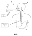
- FIG. 1 is a schematic diagram illustrating an acidity monitoring system 10 shown in conjunction with a patient 12.
- Acidity monitoring system 10 measures the acidity within the lower portion of an esophagus 14 of patient 12. More specifically, acidity monitoring system 10 measures the acidity level near the lower esophageal sphincter (LES) of patient 12, i.e., where esophagus 14 meets stomach 16. Measuring the acidity level of the lower portion of esophagus 14 allows a physician to more accurately diagnose Gastroesophageal Reflux Disease (GERD).
- LES lower esophageal sphincter
- system 10 is described in this disclosure in terms of sensing acidity in the esophagus, the system may be adapted for application to a variety of other sensing environments, and to a variety of different sensing applications. In other words, system 10 may be used for monitoring other locations within patient 12 or monitoring other body parameters.
- the LES normally relaxes to allow food to enter into stomach 16 from esophagus 14. The LES then contracts to prevent stomach contents from entering esophagus 14.
- the LES relaxes too frequently or at inappropriate times allowing stomach contents to reflux into the esophagus 14, increasing the acidity level near the lower portion of esophagus 14, which may lead to complications such as heartburn, painful swallowing, difficulty swallowing, coughing, wheezing, asthma, inflammation of the vocal cords or throat, esophageal ulcers, narrowing of the esophagus, and in the worst cases Barrett's esophagus.
- Acidity monitoring system 10 includes a capsule 18 for sensing acidity.
- Capsule 18 includes an acidity sensor, e.g., a pH sensor (not shown), to measure the acidity level within esophagus 14.
- the pH sensor carried by capsule 18 may generally conform to the pH sensor employed in monitoring devices, such as those described in U.S. Patent Nos. 6,285,897 and 6,689,056 to Kilcoyne et al .
- Capsule 18 may be in wireless communication with a receiver 20.
- capsule 18 may transmit measured acidity data to receiver 20 via a transmitter and an antenna (not shown).
- Receiver 20 may, for example, comprise a portable receiver that is carried by patient 12.
- the information stored within receiver 20 may be downloaded by a physician to a computing device and analyzed to diagnose the condition of patient 12.
- capsule may include a memory that stores the measured data, thus permitting recovery of the data after capsule 18 is passed through patient 12.
- a delivery device 22 attaches capsule 18 to a wall of esophagus 14 and, more particularly, to esophageal tissue within esophagus 14.
- Delivery device 22 includes a proximal portion, referred to herein as a handle 24, and an elongated probe 26 that extends from handle 24 into esophagus 14 of patient 12.
- Elongated probe 26 is configured to carry capsule 18 for deployment within patient 12.
- Capsule 18 may, for example, be coupled to a distal end of delivery device 22 for delivery to a particular location within esophagus 14.
- delivery device 22 may utilize a single actuator, such as a drive wire (not shown), to both anchor capsule 18 to esophagus 14 in a first motion and release the capsule from delivery device 22 in a second motion.
- delivery device 22 includes a vacuum inlet 28 on handle 24 to couple delivery device 22 to a vacuum 30.
- Vacuum 30 applies suction within an inner lumen formed by probe 26.
- a vacuum outlet (not shown) at the distal end of probe 26 and, more particularly, at the interface between probe 26 and capsule 18, applies the suction from vacuum 30 to the wall of esophagus 14 in order to draw esophageal tissue into a void within capsule 18.
- Delivery device 22 anchors capsule 18 to the esophageal tissue drawn into the void of capsule 18 and disengages from capsule 18, thereby leaving capsule 18 attached to the wall of esophagus 14.
- the actuator is configured to activate an anchor element during a first motion to anchor capsule 18 to the wall of esophagus 14.
- the actuator is also configured to activate a release mechanism during a second motion to cause a retention mechanism coupled to capsule 18 to detach from capsule 18, thus releasing capsule 18 from delivery device 22.
- the first motion and second motion may be movement in substantially opposite directions.
- the actuator may activate the anchor element during a forward motion and activate a release mechanism during a rearward motion.
- the first and second motion may be movement in substantially the same direction.
- the actuator may activate an anchor element during a forward motion to a first position and activate the release mechanism during a forward motion to a second position. Allowing the physician to place capsule 18 with a single actuator, in accordance with this disclosure, may make the delivery system more reliable and easier to operate. Additionally, the delivery system may be less costly to produce.
- the acidity sensor of capsule 18 While on the wall of esophagus 14, the acidity sensor of capsule 18 obtains acidity measurements for a period of time, e.g., several hours or several days, and relays the acidity measurements to receiver 20 via wireless telemetry. Capsule 18 eventually detaches from the wall of the esophagus and is passed through the digestive system of patient 12. For some applications, however, in the esophagus or in other body lumens, tissue sites, or organs, capsule 18 may be designed for more persistent placement, such that the capsule may remain attached within the patient for several weeks, months, or possibly years.
- the techniques of this disclosure are described in terms of delivering a capsule 18 for sensing acidity of esophagus 14 of the patient, the techniques of the disclosure may be applied for delivery of other types of sensors to different tissue locations or organs. Moreover, the techniques of this disclosure may be used to place other therapeutic devices, drugs or other agents to locations within patient 12.
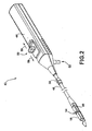
- FIG. 2 is a schematic diagram illustrating an exemplary delivery device 40 for delivering a capsule 18 to a location within a patient, substantially as shown in FIG. 1 .
- Delivery device 40 includes a handle 44 and an elongated probe 46 that extends from handle 44.
- Delivery device 40 also includes a capsule coupling mechanism 48 at a distal end of probe 46 that is coupled to capsule 18 to secure capsule 18 to delivery device 40 during placement of capsule 18.
- Delivery device 40 places capsule 18 at an appropriate tissue location along esophagus 14 ( FIG. 1 ), anchors capsule 18 to the appropriate location during a first motion of an actuator and releases capsule 18 during a second motion of the actuator. In this manner, delivery device 40 is capable of anchoring capsule 18 to a tissue location and releasing capsule 18 from delivery device 40 using a single actuator.
- the actuator may comprise a drive wire.
- Delivery device 40 includes a controller 50 located on handle 44 that controls operation of the actuator, e.g., drive wire, to anchor capsule 18 to the wall of esophagus 14 and release capsule 18 from delivery device 40.
- Controller 50 may comprise a sliding button that is successively pushed through different stages to perform sequential operations during the delivery of capsule 18 to the appropriate location along esophagus 14.
- controller 50 may comprise a dial, switch, or similar control mechanism that can be switched to different settings to perform different functions, e.g., by linear or rotational movement.
- controller 40 may be manually activated, e.g., by a physician's hand, or automatically activate, e.g., by a motor or other drive mechanism in response to physician action.
- the distal end of delivery device 40 which carries capsule 18, enters esophagus 14 and extends through esophagus 14 to a location five to six centimeters above the LES, i.e., the tissue location of interest in this example.
- the distal end of delivery device 40 may be guided to the LES using a number of different techniques.
- delivery device 40 may detect a pressure variation, such as a pressure variation between the stomach and the esophagus, to identify the location of the LES.
- the user of delivery device 40 may use external imaging techniques, such as ultrasound or fluoroscopy, to track the location of the distal end of delivery device 40.
- the distal end of delivery device 40 is inserted into patient 12 until a depth marker 56 reaches a particular location. Depth marker 56 may be moved up or down probe 46 based on the approximate length of esophagus 14 of patient 12.
- delivery device Upon identifying the appropriate location for placement of capsule 18, delivery device opens vacuum inlet 52. Controller 50 may control opening and closing of vacuum inlet 52 and, thus, application of suction from vacuum 30 ( FIG. 1 ). Controller 50 may open vacuum inlet 52 upon actuation of controller 50. Alternatively, the user of delivery device 40 may control application of the suction from vacuum 30 by turning on and off vacuum 30. Vacuum inlet 52 receives sufficient suction pressure from vacuum 30 to draw a portion of esophageal tissue into a void 54 of capsule 18.
- controller 50 Upon drawing the esophageal tissue into void 54, controller 50 is adjusted to cause delivery device 40 to anchor capsule 18 to the esophageal tissue drawn into void 54.
- controller 50 may slide toward the distal end of delivery device 40, i.e., in a forward direction, to cause the drive wire to deploy an anchor element that is configured to anchor sensing capsule 18 to a wall of esophagus 14.
- the drive wire may deploy a pin through the esophageal tissue when controller 50 is advanced in the forward motion. The forward motion is motion in the direction of arrow 58.
- a pin is described for purposes of illustration, other types of anchoring elements may be used.
- 6,285,897 and 6,689,056 to Kilcoyne et al provide examples of a variety of anchoring elements for attaching monitoring devices to the lining of the esophagus.
- the anchoring elements described in the Kilcoyne et al. patents may be suitable for attachment of capsule 18.
- delivery device 40 After capsule 18 is anchored to the wall of esophagus 14, delivery device 40 releases capsule 18, thereby leaving capsule 18 attached to the wall of esophagus 14.
- Delivery device 40 may release capsule 18 during a rearward motion of the drive wire.
- the rearward motion is motion in the direction of arrow 59.
- the drive wire activates a release mechanism that releases capsule 18 from delivery device 40.
- rearward motion of the drive wire may cause a retention mechanism, such as one or more prongs, within capsule coupling mechanism 48 to disengage from capsule 18, thus releasing capsule 18 from delivery device 40.
- delivery device 40 anchors capsule 18 to the tissue and releases capsule 18 from delivery device 40 using a single actuator.
- Delivery device 40 is then removed and a sensor of capsule 18 begins to measure one or more parameters of esophagus 14 over time and transmit the information to receiver 20 via wireless communication, e.g., via a transmitter and an antenna.
- the sensor of capsule 18 may measure one or more parameters that indicate an acidity of esophagus 14. Such operation is described above with respect to FIG. 1 .
- FIG. 3 is a schematic diagram illustrating an exploded view of exemplary delivery device 40 of FIG. 2 .
- the exploded view of delivery device 40 illustrates various example components of delivery device 40.
- Delivery device 40 includes a slider button 60, a slider 62 and a slider lock 64.
- Slider button 60 and slider 62 couple together to form a controller 50 ( FIG. 2 ) that is successively placed in different positions to perform sequential control operations during delivery of capsule 18.
- Slider lock 64 locks controller 50 to prevent inadvertent movement of controller 50 during packing, shipping or unpacking. Hence, when slider lock 64 is coupled to controller 50, controller 50 is unable to move in any direction. Slider lock 64 is disengaged prior to use of delivery device 40.
- Delivery device 40 further includes an upper handle body 66A and a lower handle body 66B.
- Upper handle body 66A and lower handle body 66B couple together to form handle 44 ( FIG. 2 ).
- Upper handle body 66A is formed to include a slide groove 68. Slider button 60 and slider 62 fit into slide groove 68, and slide forward and backward in slide groove 68 in response to force applied by a user of the device.
- Lower handle body 66B is formed to include a vacuum inlet 52 that couples to a vacuum ( FIG. 1 ) to provide suction.
- Upper handle body 66A and lower handle body 66B are formed to include a groove 69.
- FIG. 3 only illustrates the portion of groove 69 formed in lower handle body 66B.
- upper handle body 66A also includes a similar groove portion.
- Groove 69 receives an element that slides within groove 69, such as a spring element 70.
- Groove 69 is formed to allow controller 50 to only move in the forward direction initially.
- spring element 70 may fit into a first portion of groove 69 in a manner that prevents initial movement in the rearward direction.
- controller 50 is still unable to be move in a rearward direction after slide lock 64 is removed.
- groove 69 and spring element 70 form a means for preventing inadvertent release of capsule 18 from delivery device 22 by preventing controller 50 from moving in the rearward direction until anchor element 80 is deployed.
- the means for preventing movement in the rearward direction until anchor element 80 is deployed may be realized using other mechanical or electromechanical mechanisms.
- groove 69 may receive elements other than spring element 70.
- Delivery device 40 also includes a drive wire adaptor 72.
- drive wire adaptor 72 advances a drive wire 74 to anchor capsule 18 to the wall of esophagus 14.
- drive wire adaptor 72 is formed to have at least two sections of different diameters.
- the different diameter sections of drive wire adaptor 72 assist in creating a vacuum chamber within delivery device 40, as described below.
- the larger diameter portion of drive wire adaptor 72 is located within a center of a seal 75.
- the larger diameter portion of drive wire adaptor 72 and seal 75 create a vacuum chamber within a forward region 81 of delivery device 40.
- the vacuum chamber extends from seal 75 through probe 46 and a vacuum channel 88 into a void 54 of capsule 18.
- Vacuum channel 88 may be integrated into one of the other elements of delivery device 40, such as within a capsule coupling housing 86, which is described below. While drive wire adaptor 72 is advanced forward to anchor capsule 18, the larger diameter portion of drive wire adaptor 72 remains seated within the central aperture of seal 75, maintaining the vacuum seal.
- drive wire adaptor 72 retracts from seal 75 until the smaller diameter portion of drive wire adaptor 72 is located within the center of seal 75. The smaller diameter portion of drive wire adaptor 72 does not fill the entire central aperture of seal 75. When this occurs, the vacuum chamber within delivery device 40 is vented, thus reducing the suction force caused by the attached vacuum 30 ( FIG. 1 ).
- Drive wire 74 is located within an inner lumen formed by probe 46, and runs the length of delivery device 40.
- the length of probe 46 and drive wire 74 may be much longer than they appear in FIG. 3 .
- probe 46 and drive wire 74 may be approximately twenty to thirty inches (fifty to seventy-five centimeters).
- Drive wire 74 and probe 46 are illustrated in FIG. 3 in shorter lengths for ease of illustration.
- a depth marker 56 may be adjusted along probe 46 to measure a length of probe 46 for insertion into a patient 12.
- Drive wire 74 includes a protrusion, such as a ball portion 76, located at the distal end of drive wire 74.
- Ball portion 76 is constructed such that during rearward motion, ball portion 76 engages with a release mechanism to release capsule 18 from delivery device 40 as described below.
- the protrusion at the distal end of drive wire 74 is shaped like a ball, the protrusion may take other forms such as a square, a T-shape or the like.
- the distal portion of delivery device 40 includes a nose 78. Nose 78 couples to an anchor element 80, a release mechanism 82 and a capsule coupling mechanism 84. Capsule coupling mechanism 84 fits into a capsule coupling housing 86. As illustrated in FIG. 3 , capsule coupling mechanism 84 includes a retention mechanism, such as one or more prongs, that couple to capsule 18. As will be described in detail, the prongs of capsule coupling mechanism 84 engage with channel-like detents formed on capsule 18 to securely couple capsule 18 to delivery device 40 during delivery to a tissue location.
- a retention mechanism such as one or more prongs
- Anchor element 80 is configured to anchor capsule 18 to tissue that is suctioned into void 54.
- Anchor element 80 anchors capsule 18 to the tissue in void 54 during forward motion of controller 50.
- anchor element 80 may comprise a locking pin that is driven through the tissue in void 54 in response to forward motion of controller 50. More specifically, the forward motion of controller 50 causes drive wire 74 to advance forward to drive the locking pin through the tissue suctioned into void 54 of capsule 18.
- other type of anchor elements may be used in place of the locking pin.
- release mechanism 82 comprises a cam that interacts with capsule coupling mechanism 84 to release capsule 18.
- an enlarged portion of drive wire 74 such as ball portion 76, engages with the cam during rearward motion to cause the cam to retract towards handle 44.
- the retraction of the cam toward handle 44 causes the prongs of capsule coupling mechanism 84 to expand outwards to release capsule 18: In this manner, the cam acts as a release mechanism that releases capsule 18 from delivery device 40.
- FIG. 4 is a cross-sectional view of a side of a handle 44 of exemplary delivery device 40.
- a user of delivery device 40 interacts with controller 50 of handle 44 to anchor capsule 18 to the tissue location of interest and to release capsule 18 from delivery device 40.
- controller 50 is located in a position such that the only direction in which controller 50 may be moved is in a forward direction.
- Spring element 70 may, for example, be aligned in a first channel of groove 69 in order to only permit movement of controller 50 in the forward direction.
- the larger diameter portion of drive wire adaptor 72 is located within a center of a seal 75 as illustrated in FIG. 4 .
- the larger diameter portion of drive wire adaptor 72 and seal 75 create a vacuum chamber within delivery device 40.
- the vacuum chamber extends from seal 75 through probe 26 and vacuum channel 88 ( FIG. 3 ) into a void 54 of capsule 18.
- drive wire adaptor 72 advances drive wire 74 forward.
- the advancement of drive wire 74 causes an anchor element to anchor capsule 18 to the tissue within void 54. In this position, the larger diameter portion of drive wire adaptor 72 still remains within seal 75 and thus the vacuum chamber is still intact.
- spring element 70 moves into a second channel of groove 69 that allows for movement of controller 50 in a rearward direction further along handle than the original position of controller 50.
- drive wire adaptor 72 causes drive wire 74 to retract toward handle 44 of delivery device 40.
- Drive wire 74 engages release mechanism 82 ( FIG. 3 ) while moving in the rearward direction, causing the capsule coupling mechanism 84 ( FIG. 3 ) to release the capsule 18.
- controller 50 moves in the rearward direction to cause retraction of drive wire adaptor 72 until the smaller diameter portion of drive wire adaptor 72 is located within the center of seal 75.
- the vacuum chamber within delivery device 40 is vented, thus redirecting the suction force caused by the attached vacuum 30 ( FIG. 1 ).
- the suction force caused by the attached vacuum 30 may be manually controlled by the user of delivery device 40.
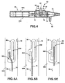
- FIGS. 5A-5C are schematic diagrams illustrating exemplary operation of an embodiment of a locking mechanism of the invention that includes a spring element 70 within groove 69 to prevent inadvertent release of capsule 18.
- FIGS. 5A-5C illustrate a groove 69 formed in a lower handle body 66B of delivery device 40, and the interaction between groove 69 and spring element 70 to prevent inadvertent release of capsule 18.
- upper handle body 66A also includes a similar groove portion which interacts with a spring element 70 in a similar manner.
- Groove 69 includes a first groove channel 90A and a second groove channel 90B. As illustrated in detail in FIGS. 5A-5C , first groove channel 90A is shorter than second groove channel 90B. In other words, second groove channel 90B extends further in the rearward direction (represented by arrow 59) than first groove channel 90A. Arrow 59 points in the opposite direction of elongated probe 46 ( FIG. 2 ).
- FIG. 5A shows the initial position of spring element 70 within the groove 69. Spring element 70 is initially positioned within first groove channel 90A. Because first groove channel 90A is shorter than second groove channel 90B, spring element 70 is prevented from initially moving in the rearward direction. Controller 50, which is coupled to spring element 70, is therefore also prevented from initially moving in the rearward direction. Since no movement in the rearward direction is permitted by spring element 70, drive wire 76 cannot activate the release mechanism to inadvertently release capsule 18 from delivery device 40 before the capsule 18 is anchored to the tissue site.
- FIG. 5B illustrates the positioning of spring element 70 within groove 69 when controller 50 moves in the forward direction (indicated by arrow 58). Arrow 58 points toward elongated probe 46 of FIG. 2 .
- spring element 70 moves to the portion of groove 69 in which groove channel 90A and groove channel 90B are communicatively coupled.
- the positioning of spring element 70 illustrated in FIG. 5B may, for example, correspond to the distal end of delivery device 40 anchoring capsule 18 to the tissue at the specific site.
- FIG. 5C illustrates the positioning of spring element 70 within groove 69 after anchoring capsule 18 to the tissue at the specific site.
- spring element 70 moves into groove channel 90B after the movement of controller 50 in the forward direction.
- Groove 69 may be formed in such a manner that spring element 70 will be biased to being in groove channel 90B.
- spring element 70 may be slightly bent into groove 90A during manufacturing and thus spring over to groove channel 90B in an attempt to straighten out after moving controller 50 in the forward direction.
- controller 50 may move in the rearward direction to the rear of groove channel 90B.
- the rear of groove channel 90B is further in the rearward direction (represented by arrow 59) than the rear of groove channel 90A.
- Rearward movement of controller 50 and spring element 70 in the rearward direction corresponds to the distal end of delivery device releasing capsule 18 from the delivery device 40.
- groove 69 and spring element 70 prevent inadvertent release of capsule 18 from deliver device 40 by preventing controller 50 from initially moving in the rearward direction, which would engage the release mechanism.
- FIG. 5 is described with reference to groove 69 receiving a spring element 70, groove 69 may receive other elements to perform the same function as spring element 70. Moreover other types of grooves may be formed that perform the same function, i.e., preventing inadvertent release of capsule 18.
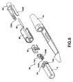
- FIG. 6 is a schematic diagram illustrating an exploded view of the distal end of delivery device 40 in further detail.
- the distal end of delivery device 40 includes a nose 78 that couples to an anchor element 80, a release mechanism 82 and a capsule coupling mechanism 84.
- Capsule coupling mechanism 84 fits into a capsule coupling housing 86.
- capsule coupling mechanism 84 includes prongs 100A and 100B (collectively, "prongs 100").
- Prong 100B of capsule coupling mechanism 84 engages with a channel 106 formed on capsule 18 to securely couple capsule 18 to delivery device 40 during delivery to a tissue location. Although only a single channel 106 is illustrated in FIG.
- capsule coupling mechanism 84 may include more than two prongs that attach to capsule 18.
- Anchor element 80 anchors capsule 18 to tissue that is suctioned into void 54 via suction delivered through vacuum channel 88.
- Anchor element 80 anchors capsule 18 to the tissue in void 54 during forward motion of controller 50.
- anchor element 80 may comprise a locking pin 102 that is driven through the tissue in void 54 in response to forward motion of controller 50.
- Anchor element 80 also includes tangs 104A and 104B (collectively, "tangs 104") that fit in channels within capsule 18 and couple the anchor element 80 to capsule 18. In this manner, anchor element 80 becomes a part of capsule 18.
- anchor element 80 may be incorporated within capsule 18 and advance through the tissue in void 54. In this case, drive wire 74 anchor element 80 is always a part of the capsule 18.
- release mechanism 82 comprises a cam that interacts with capsule coupling mechanism 84 to release capsule 18.
- a ball 76 on a distal end of drive wire 74 engages with the cam during rearward motion to cause the cam to retract towards handle 44 causing prongs 100 of capsule coupling mechanism 84 to expand outwards.
- the prongs continue to expand outward until they disengage from channels 106 to release capsule 18. In this manner, the cam acts as a release mechanism that releases capsule 18 from delivery device 40.
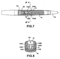
- FIG. 7 is a cross-sectional view of a top of the distal end of delivery device 40.
- the top view illustrates the coupling of capsule 18 to the distal end of delivery device 40.
- Prongs 100A and 100B of capsule coupling mechanism couple capsule 18 to delivery device 40.
- capsule 18 is formed to include channels 106A and 106B that engage with prongs 100A and 100B, respectively, of capsule coupling mechanism 80.
- release mechanism 82 During rearward motion of controller 50, drive wire 74 interacts with release mechanism 82 to release capsule 18. In particular, retraction of release mechanism 82 toward the handle of delivery device 40 causes prongs 100A and 100B to expand outward, eventually expanding outward far enough to release capsule 18 from delivery device 40. As illustrated in FIG. 7 , prongs 100 of capsule coupling mechanism 80 are formed in a ramp-like manner. Release mechanism begins to move toward the thicker portion of the ramp of prongs 100 causing prongs 100 to be pushed outward, eventually releasing capsule 18 from delivery device 40.
- FIG. 8 is a cross-sectional front view of the distal end of delivery device 40 taken from A to A' as illustrated in FIG. 7.
- FIG. 8 illustrates the coupling between capsule 18 and capsule coupling mechanism 84.
- capsule 18 includes a void 54 into which tissue is drawn in by the suction of vacuum 30 ( FIG. 1 ).
- Void 54 includes an opening 109 through which locking pin 102 enters to anchor capsule 18 to tissue suctioned within void 54.
- Capsule 18 includes anchor channels 110A and 110B that receive tangs, such as tangs 104 of anchor element 80 ( FIG. 6 ) to attach anchor element 80 to capsule 18. In this manner, anchor element 80 becomes a part of capsule 18.
- Capsule 18 also includes coupling channels 106A and 106B ("coupling channels 106"). Prongs 100A and 100B of capsule coupling mechanism 84 engage with coupling channels 106A and 106B, respectively, to couple capsule to the distal end of delivery device 40.
- prongs 100 of capsule coupling mechanism 84 may be formed in a ramp-like manner. As release mechanism 82 begins to move toward the thicker portion of the ramp of prongs 100, prongs 100 begin to be push outward to release capsule 18 from delivery device 40.
- FIGS. 9A-9C are schematic diagrams illustrating exemplary operation of a delivery device for placing capsule 18 to tissue location within a patient.
- FIGS. 9A-9C illustrate the distal end of delivery device 40 during various stages of delivery of capsule 18. More specifically, FIG. 9A illustrates an initial configuration of the distal end of delivery device 40, FIG. 9B illustrates the distal end of delivery device 40 during anchoring of capsule 18 to the tissue at the site of interest, and FIG. 9C illustrates the distal end of delivery device 40 during release of capsule 18 from delivery device 40.
- the initial configuration of the distal end of delivery device 40 is such that the anchor element 80 is not engaged with capsule 18.
- the initial configuration of the distal end of delivery device 40 is the configuration in which the delivery device would be upon initial receipt of the product.
- the configuration illustrated in FIG. 9A corresponds with the configuration of the handle portion described above with reference to FIG. 5A .
- spring element 70 is initially positioned within first groove channel 90A such that controller 50 is prevented from initially moving in the rearward direction. Since no movement in the rearward direction is permitted by spring element 70, drive wire 74 cannot activate the release mechanism to inadvertently release capsule 18 from delivery device 40 before the capsule 18 is anchored to the tissue site.
- delivery device Upon identifying the appropriate location for placement of capsule 18, delivery device opens vacuum inlet 52 ( FIG. 2 ). Vacuum inlet 52 receives sufficient suction pressure from vacuum 30 ( FIG. 1 ) to draw a portion of esophageal tissue into a void 54 of capsule 18. Controller 50 is moved in a forward direction to cause delivery device 40 to anchor capsule 18 to the esophageal tissue. More specifically, the forward movement of controller 50 causes drive wire 74 to drive anchor element 80 through the tissue within void 54 to anchor capsule 18 to the wall of esophagus 14, as illustrated in FIG. 9B .
- the configuration illustrated in FIG. 9B corresponds with the configuration of the handle portion described above with reference to FIG. 5B . More specifically, spring element 70 moves to the portion of groove 69 in which spring channel 90A and spring channel 90B are communicatively coupled.
- controller 50 is moved in a rearward direction causing drive wire to retract toward handle 44 of delivery device 40.
- ball portion 76 of drive wire 74 engages with a release mechanism 82, such as a cam, during rearward motion to cause the cam to retract towards handle 44.
- ball portion 76 may be sized so that it cannot fit through a hole in release mechanism 82, thereby causing drive wire 74 to exert a pulling force on the release mechanism when the drive wire is pulled backward away from capsule 18.
- Release mechanism 82 begins to move toward the thicker portion of the ramp of prongs 100 causing prongs 100 to be pushed outward, eventually releasing capsule 18 from delivery device 40.
- 9C corresponds with the configuration of the handle portion described above with reference to FIG. 5C .
- spring element 70 moves into groove channel 90B such that controller 50 may move in a rearward direction past the location of the initial position. Rearward movement of controller 50 and spring element 70 in the rearward direction corresponds to the distal end of delivery device releasing capsule 18 from the delivery device 40.
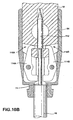
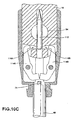
- FIGS. 10A-10C are schematic diagrams illustrating exemplary operation of another exemplary delivery device for placing capsule 18 at a tissue location within a patient.
- FIGS. 10A-10C illustrate the distal end of the delivery device during various stages of delivery of capsule 18. More specifically, FIG. 10A illustrates an initial configuration of the distal end of the delivery device, FIG. 10B illustrates the distal end of the delivery device during anchoring of capsule 18 to the tissue at the site of interest, and FIG. 10C illustrates the distal end of the delivery device during release of capsule 18 from the delivery device.
- the distal portion of the delivery device includes an anchor element 112 and a capsule coupling mechanism formed from latch 114A and latch 114B (collectively, “latches 114"). As illustrated in FIG. 10 , latches 114 of the capsule coupling mechanism engage with respective ones of channels 116A and 116B formed on capsule 18 to securely couple capsule 18 to the delivery device during delivery of capsule 18 to a tissue location.
- anchor element 112 separates latches 114.
- Anchor element 112 is used to anchor capsule 18 to tissue that is suctioned into void 54.
- Anchor element 112 is pushed forward by drive wire 74 during forward movement of controller 50 to anchor capsule 18 to the tissue in void 54.
- FIG. 10B illustrates the distal end of the delivery device after anchor element 112 is pushed forward. As shown in FIG. 10B , anchor element 112 no longer separates latches 114. However, drive wire 74 is located between latches 114 during movement in the forward direction and thus continues to separate latches 114.
- drive wire 74 and anchor element 112 are of substantially the same thickness and diameter.
- FIG. 10C illustrates the distal end of the delivery device after retraction of drive wire 74.
- latches 114 open to release capsule 18.
- the latches are biased so that the ends not coupling to capsule 18 push toward one another.
- the ends of latches 114 may, for example, be biased to push toward one another using a spring mechanism that causes the portion of latches 114 separated by drive wire 74 to come together.
- Latches 114 may be biased using other biasing means, such as a magnet.
- FIG. 11 is a flow diagram illustrating exemplary operation of delivery device 40 placing a capsule 18 to an esophagus 14 of the patient.
- delivery device 40 places the distal end of delivery device 40 at tissue at a site of interest (120).
- the distal end of delivery device 40 enters esophagus 14, via either the nasal or oral cavity, and extends through esophagus 14 to the LES.
- delivery device 40 Upon identifying the appropriate location for anchoring of capsule 18, delivery device 40 opens vacuum inlet 28 (122). Delivery device 40 receives suction pressure from vacuum 30 to draw esophageal tissue into a void of capsule 18 (124). Delivery device 40 anchors capsule 18 to the wall of esophagus 14 during a first motion of an actuator (126). For example, delivery device 40 may advance drive wire 74 to drive a locking pin through the esophageal tissue in the void of capsule 18 to anchor the capsule 18 when controller 50 is advanced in a forward direction.
- delivery device releases capsule 18 during a second motion of the actuator, thereby leaving capsule 18 anchored to esophagus 14 (128).
- movement of controller 50 may cause drive wire 74 to activate a release mechanism to release capsule 18.
- rearward motion of drive wire 74 may engage a cam, which causes prongs 100 of a capsule coupling mechanism 84 to expand and detach from capsule 18.
- drive wire 74 may separate latches 114 ( FIG. 10 ) that are spring biased toward one another, and rearward motion of the drive wire 74 may result in drive wire 74 no longer separating latches 114. In this case, latches 114 push toward one another to release capsule 18.
- the first and second motion may be motion in substantially opposite directions.
- the actuator may activate the anchor element during a forward motion and activate a release mechanism during a rearward motion.
- the first and second motion may be motion in substantially the same direction.
- the actuator may activate an anchor element during a forward motion to a first position and activate the release mechanism during a forward motion to a second position.
- capsule 18 may transmit the measurements to receiver 20 and/or to an external or implanted therapy device, such as an electrical neurostimulator or a drug delivery device.
- an electrical neurostimulator or a drug delivery device may be responsive to measurements obtained by capsule 18 to delivery therapy based on the measurements.
- a neurostimulator, drug delivery device, or other therapeutic device may be responsive to commands transmitted by receiver 20 to the device, in which case receiver 20 generates the commands based on the measurements obtained by capsule 18.
- the techniques of the disclosure may be applied for delivery of other types of sensors to different body lumens, tissue locations or organs within a patient.
- the techniques of this disclosure may be used to place other therapeutic devices, such as neurostimulators, drug delivery devices, drug release devices, or other devices to locations within patient.
- the techniques and system of this disclosure may be used to place in the stomach or other location in the gastrointestinal tract an intra-luminal device for gastrointestinal electrical stimulation such as one of such devices described in U.S. Application Serial No. 10/801,230 , published as Publication No. 2005/0209653 to Herbert, et al. ,.
- such a system may be used to sense physiological conditions within different body lumens, such as the esophagus, stomach, intestines, urethra, bladder, or colon.
- the system may be adapted for urodynamic testing, urinalysis, or other diagnostic evaluations pertinent to the urinary tract, e.g., as described in U.S. Published Patent Application No. 2005/0245840 to Christopherson et al .
- the techniques are not limited to application for monitoring associated with any particular disorder, condition or affliction.
- a monitoring device in accordance with the techniques of this disclosure can be used to monitor other types of physiological conditions, such as conditions indicative of pregnancy, ovulation, or the condition of a fetus.
Abstract
Description
- This disclosure relates to medical devices and, more particularly, to medical devices for monitoring physiological conditions within a body lumen.
- Gastroesophageal reflux occurs when stomach acid intermittently surges into the esophagus. It is common for most people to experience this acid reflux occasionally as heartburn. Gastroesophageal reflux disease (GERD) is a clinical condition in which the reflux of stomach acid into the esophagus is frequent enough and severe enough to impact a patient's normal functioning or to cause damage to the esophagus.
- In the lower part of the esophagus, where the esophagus meets the stomach, there is a muscular valve called the lower esophageal sphincter (LES). Normally, the LES relaxes to allow food to enter into the stomach from the esophagus. The LES then contracts to prevent stomach acids from entering the esophagus. In GERD, the LES relaxes too frequently or at inappropriate times, allowing stomach acids to reflux into the esophagus.
- The most common symptom of GERD is heartburn. Acid reflux also leads to esophageal inflammation, which causes symptoms such as painful swallowing and difficulty swallowing. Pulmonary symptoms such as coughing, wheezing, asthma, or inflammation of the vocal cords or throat may occur in some patients. More serious complications from GERD include esophageal ulcers and narrowing of the esophagus. The most serious complication from chronic GERD is a condition called Barrett's esophagus in which the epithelium of the esophagus is replaced with abnormal tissue. Barrett's esophagus is a risk factor for the development of cancer of the esophagus.
- Accurate diagnosis of GERD is difficult but important. Accurate diagnosis allows identification of individuals at high risk for developing the complications associated with GERD. It is also important to be able to differentiate between gastroesophageal reflux, other gastrointestinal conditions, and various cardiac conditions. For example, the similarity between the symptoms of a heart attack and heartburn often lead to confusion about the cause of the symptoms. Esophageal manometry, esophageal endoscopy, and esophageal pH monitoring are standard methods of measuring esophageal exposure to stomach acids and are currently used to diagnose GERD.
-
US 2004/0260164 A1 describes an implantable monitoring probe provided with an outer shell for enclosing a transducer, such as a pH sensor. The shell has a tissue attachment cavity for attaching the probe at an attachment site. The shell can be removably connected to a delivery catheter. -
US 2005/0165272 A1 describes an endoscope system having an insertion section to be inserted into a body cavity, an introducer for performing treatmenrt in the body cavity, and a capsule endoscope. The capsule endoscope is used in combination with the introducer. -
WO 02/087657 A2 - The object of the application is to provide improved techniques for placing a capsule used for sensing one or more parameters within a body lumen of a patient. This object is achieved by the subject-matter of claim 1. Advantageous embodiments are described in the dependent claims.
- In general, this disclosure describes techniques for placing a capsule used for sensing one or more parameters within a body lumen of a patient. A delivery device may be configured to anchor the capsule to tissue at a specific site within the body lumen during a first motion of an actuator and release the capsule from the delivery device during a second motion of the actuator. In this manner, a user may place the capsule by interacting with a single actuator.
- The details of one or more embodiments are set forth in the accompanying drawings and the description below. Other features, objects, and advantages of the described techniques will be apparent from the description and drawings, and from the claims.
-
-
FIG. 1 is a schematic diagram illustrating an esophageal acidity monitoring system shown in conjunction with a patient. -
FIG. 2 is a perspective diagram illustrating an exemplary delivery device for placing a capsule at a location within body lumen of a patient. -
FIG. 3 is a schematic diagram illustrating an exploded view of the delivery device ofFIG. 2 . -
FIG. 4 is a cross-sectional side view of a handle portion of the delivery device ofFIG. 2 . -
FIGS. 5A-5C are top views illustrating an exemplary locking structure for preventing inadvertent release of a capsule from a delivery device such as that shown inFIGS. 2-4 . -
FIG. 6 is a schematic diagram illustrating an exploded view of a distal end of the delivery device ofFIG. 2 in further detail. -
FIG. 7 is a cross-sectional top view of the distal end of delivery device shown inFIG. 6 . -
FIG. 8 is a cross-sectional view from A to A' of the distal end of a delivery device. -
FIGS. 9A-9C are schematic diagrams illustrating exemplary operation of a distal end of an exemplary delivery device during various stages of delivery of a capsule. -
FIGS. 10A-10C are schematic diagrams illustrating exemplary operation of a distal end of another exemplary delivery device during various stages of delivery of a capsule. -
FIG. 11 is a flow diagram illustrating exemplary operation of a delivery device placing a capsule at a location within a patient. - In general, this disclosure describes techniques for placing an implantable capsule used for sensing one or more parameters within a body lumen of a patient. A delivery device may be configured to anchor the capsule to tissue at a specific site within the body lumen during a first motion of an actuator and release the capsule from the delivery device during a second motion of the actuator. In this manner, a user may place the capsule by interacting with a single actuator.
-
FIG. 1 is a schematic diagram illustrating anacidity monitoring system 10 shown in conjunction with apatient 12.Acidity monitoring system 10 measures the acidity within the lower portion of anesophagus 14 ofpatient 12. More specifically,acidity monitoring system 10 measures the acidity level near the lower esophageal sphincter (LES) ofpatient 12, i.e., whereesophagus 14 meetsstomach 16. Measuring the acidity level of the lower portion ofesophagus 14 allows a physician to more accurately diagnose Gastroesophageal Reflux Disease (GERD). Althoughsystem 10 is described in this disclosure in terms of sensing acidity in the esophagus, the system may be adapted for application to a variety of other sensing environments, and to a variety of different sensing applications. In other words,system 10 may be used for monitoring other locations withinpatient 12 or monitoring other body parameters. - As described above, the LES normally relaxes to allow food to enter into
stomach 16 fromesophagus 14. The LES then contracts to prevent stomach contents from enteringesophagus 14. In GERD, the LES relaxes too frequently or at inappropriate times allowing stomach contents to reflux into theesophagus 14, increasing the acidity level near the lower portion ofesophagus 14, which may lead to complications such as heartburn, painful swallowing, difficulty swallowing, coughing, wheezing, asthma, inflammation of the vocal cords or throat, esophageal ulcers, narrowing of the esophagus, and in the worst cases Barrett's esophagus. -
Acidity monitoring system 10 includes acapsule 18 for sensing acidity.Capsule 18 includes an acidity sensor, e.g., a pH sensor (not shown), to measure the acidity level withinesophagus 14. The pH sensor carried bycapsule 18 may generally conform to the pH sensor employed in monitoring devices, such as those described inU.S. Patent Nos. 6,285,897 and6,689,056 to Kilcoyne et al .Capsule 18 may be in wireless communication with areceiver 20. Thus,capsule 18 may transmit measured acidity data toreceiver 20 via a transmitter and an antenna (not shown).Receiver 20 may, for example, comprise a portable receiver that is carried bypatient 12. The information stored withinreceiver 20 may be downloaded by a physician to a computing device and analyzed to diagnose the condition ofpatient 12. Alternatively, capsule may include a memory that stores the measured data, thus permitting recovery of the data aftercapsule 18 is passed throughpatient 12. - A
delivery device 22 attachescapsule 18 to a wall ofesophagus 14 and, more particularly, to esophageal tissue withinesophagus 14.Delivery device 22 includes a proximal portion, referred to herein as ahandle 24, and anelongated probe 26 that extends fromhandle 24 intoesophagus 14 ofpatient 12.Elongated probe 26 is configured to carrycapsule 18 for deployment withinpatient 12.Capsule 18 may, for example, be coupled to a distal end ofdelivery device 22 for delivery to a particular location withinesophagus 14. As will be described in detail below,delivery device 22 may utilize a single actuator, such as a drive wire (not shown), to bothanchor capsule 18 toesophagus 14 in a first motion and release the capsule fromdelivery device 22 in a second motion. - In the example of
FIG. 1 ,delivery device 22 includes avacuum inlet 28 onhandle 24 to coupledelivery device 22 to avacuum 30.Vacuum 30 applies suction within an inner lumen formed byprobe 26. A vacuum outlet (not shown) at the distal end ofprobe 26 and, more particularly, at the interface betweenprobe 26 andcapsule 18, applies the suction fromvacuum 30 to the wall ofesophagus 14 in order to draw esophageal tissue into a void withincapsule 18.Delivery device 22anchors capsule 18 to the esophageal tissue drawn into the void ofcapsule 18 and disengages fromcapsule 18, thereby leavingcapsule 18 attached to the wall ofesophagus 14. - In particular, the actuator is configured to activate an anchor element during a first motion to anchor
capsule 18 to the wall ofesophagus 14. The actuator is also configured to activate a release mechanism during a second motion to cause a retention mechanism coupled tocapsule 18 to detach fromcapsule 18, thus releasingcapsule 18 fromdelivery device 22. In some embodiments, the first motion and second motion may be movement in substantially opposite directions. For example, the actuator may activate the anchor element during a forward motion and activate a release mechanism during a rearward motion. In other embodiments, the first and second motion may be movement in substantially the same direction. For example, the actuator may activate an anchor element during a forward motion to a first position and activate the release mechanism during a forward motion to a second position. Allowing the physician to placecapsule 18 with a single actuator, in accordance with this disclosure, may make the delivery system more reliable and easier to operate. Additionally, the delivery system may be less costly to produce. - While on the wall of
esophagus 14, the acidity sensor ofcapsule 18 obtains acidity measurements for a period of time, e.g., several hours or several days, and relays the acidity measurements toreceiver 20 via wireless telemetry.Capsule 18 eventually detaches from the wall of the esophagus and is passed through the digestive system ofpatient 12. For some applications, however, in the esophagus or in other body lumens, tissue sites, or organs,capsule 18 may be designed for more persistent placement, such that the capsule may remain attached within the patient for several weeks, months, or possibly years. - Although the techniques of this disclosure are described in terms of delivering a
capsule 18 for sensing acidity ofesophagus 14 of the patient, the techniques of the disclosure may be applied for delivery of other types of sensors to different tissue locations or organs. Moreover, the techniques of this disclosure may be used to place other therapeutic devices, drugs or other agents to locations withinpatient 12. -
FIG. 2 is a schematic diagram illustrating anexemplary delivery device 40 for delivering acapsule 18 to a location within a patient, substantially as shown inFIG. 1 .Delivery device 40 includes ahandle 44 and anelongated probe 46 that extends fromhandle 44.Delivery device 40 also includes acapsule coupling mechanism 48 at a distal end ofprobe 46 that is coupled tocapsule 18 to securecapsule 18 todelivery device 40 during placement ofcapsule 18.Delivery device 40places capsule 18 at an appropriate tissue location along esophagus 14 (FIG. 1 ), anchorscapsule 18 to the appropriate location during a first motion of an actuator and releasescapsule 18 during a second motion of the actuator. In this manner,delivery device 40 is capable of anchoringcapsule 18 to a tissue location and releasingcapsule 18 fromdelivery device 40 using a single actuator. In one embodiment, the actuator may comprise a drive wire. -
Delivery device 40 includes acontroller 50 located onhandle 44 that controls operation of the actuator, e.g., drive wire, to anchorcapsule 18 to the wall ofesophagus 14 andrelease capsule 18 fromdelivery device 40.Controller 50 may comprise a sliding button that is successively pushed through different stages to perform sequential operations during the delivery ofcapsule 18 to the appropriate location alongesophagus 14. Alternatively,controller 50 may comprise a dial, switch, or similar control mechanism that can be switched to different settings to perform different functions, e.g., by linear or rotational movement. In some embodiments,controller 40 may be manually activated, e.g., by a physician's hand, or automatically activate, e.g., by a motor or other drive mechanism in response to physician action. - The distal end of
delivery device 40, which carriescapsule 18, entersesophagus 14 and extends throughesophagus 14 to a location five to six centimeters above the LES, i.e., the tissue location of interest in this example. The distal end ofdelivery device 40 may be guided to the LES using a number of different techniques. For example,delivery device 40 may detect a pressure variation, such as a pressure variation between the stomach and the esophagus, to identify the location of the LES. Alternatively, the user ofdelivery device 40 may use external imaging techniques, such as ultrasound or fluoroscopy, to track the location of the distal end ofdelivery device 40. In another embodiment, the distal end ofdelivery device 40 is inserted intopatient 12 until adepth marker 56 reaches a particular location.Depth marker 56 may be moved up or downprobe 46 based on the approximate length ofesophagus 14 ofpatient 12. - Upon identifying the appropriate location for placement of
capsule 18, delivery device opensvacuum inlet 52.Controller 50 may control opening and closing ofvacuum inlet 52 and, thus, application of suction from vacuum 30 (FIG. 1 ).Controller 50 may openvacuum inlet 52 upon actuation ofcontroller 50. Alternatively, the user ofdelivery device 40 may control application of the suction fromvacuum 30 by turning on and offvacuum 30.Vacuum inlet 52 receives sufficient suction pressure fromvacuum 30 to draw a portion of esophageal tissue into avoid 54 ofcapsule 18. - Upon drawing the esophageal tissue into
void 54,controller 50 is adjusted to causedelivery device 40 to anchorcapsule 18 to the esophageal tissue drawn intovoid 54. In one embodiment,controller 50 may slide toward the distal end ofdelivery device 40, i.e., in a forward direction, to cause the drive wire to deploy an anchor element that is configured to anchorsensing capsule 18 to a wall ofesophagus 14. For example, the drive wire may deploy a pin through the esophageal tissue whencontroller 50 is advanced in the forward motion. The forward motion is motion in the direction ofarrow 58. Although a pin is described for purposes of illustration, other types of anchoring elements may be used.U.S. Patent Nos. 6,285,897 and6,689,056 to Kilcoyne et al . provide examples of a variety of anchoring elements for attaching monitoring devices to the lining of the esophagus. The anchoring elements described in the Kilcoyne et al. patents may be suitable for attachment ofcapsule 18. - After
capsule 18 is anchored to the wall ofesophagus 14,delivery device 40releases capsule 18, thereby leavingcapsule 18 attached to the wall ofesophagus 14.Delivery device 40 may releasecapsule 18 during a rearward motion of the drive wire. The rearward motion is motion in the direction ofarrow 59. In particular, whencontroller 50 slides in the rearward direction the drive wire activates a release mechanism that releasescapsule 18 fromdelivery device 40. As an example, rearward motion of the drive wire may cause a retention mechanism, such as one or more prongs, withincapsule coupling mechanism 48 to disengage fromcapsule 18, thus releasingcapsule 18 fromdelivery device 40. In this manner,delivery device 40anchors capsule 18 to the tissue and releasescapsule 18 fromdelivery device 40 using a single actuator. -
Delivery device 40 is then removed and a sensor ofcapsule 18 begins to measure one or more parameters ofesophagus 14 over time and transmit the information toreceiver 20 via wireless communication, e.g., via a transmitter and an antenna. As an example, the sensor ofcapsule 18 may measure one or more parameters that indicate an acidity ofesophagus 14. Such operation is described above with respect toFIG. 1 . -
FIG. 3 is a schematic diagram illustrating an exploded view ofexemplary delivery device 40 ofFIG. 2 . The exploded view ofdelivery device 40 illustrates various example components ofdelivery device 40.Delivery device 40 includes aslider button 60, aslider 62 and aslider lock 64.Slider button 60 andslider 62 couple together to form a controller 50 (FIG. 2 ) that is successively placed in different positions to perform sequential control operations during delivery ofcapsule 18.Slider lock 64locks controller 50 to prevent inadvertent movement ofcontroller 50 during packing, shipping or unpacking. Hence, whenslider lock 64 is coupled tocontroller 50,controller 50 is unable to move in any direction.Slider lock 64 is disengaged prior to use ofdelivery device 40. -
Delivery device 40 further includes anupper handle body 66A and alower handle body 66B.Upper handle body 66A andlower handle body 66B couple together to form handle 44 (FIG. 2 ).Upper handle body 66A is formed to include aslide groove 68.Slider button 60 andslider 62 fit intoslide groove 68, and slide forward and backward inslide groove 68 in response to force applied by a user of the device. -
Lower handle body 66B is formed to include avacuum inlet 52 that couples to a vacuum (FIG. 1 ) to provide suction.Upper handle body 66A andlower handle body 66B are formed to include agroove 69. For simplicity,FIG. 3 only illustrates the portion ofgroove 69 formed inlower handle body 66B. However,upper handle body 66A also includes a similar groove portion.Groove 69 receives an element that slides withingroove 69, such as aspring element 70.Groove 69 is formed to allowcontroller 50 to only move in the forward direction initially. For example,spring element 70 may fit into a first portion ofgroove 69 in a manner that prevents initial movement in the rearward direction. Thus,controller 50 is still unable to be move in a rearward direction afterslide lock 64 is removed. - As will be described in detail, after
controller 50 is initially moved forward,spring element 70 moves from the first portion ofgroove 69 into a second portion ofgroove 69. The second portion ofgroove 69 allows for movement in the rearward direction. In this manner, groove 69 andspring element 70 form a means for preventing inadvertent release ofcapsule 18 fromdelivery device 22 by preventingcontroller 50 from moving in the rearward direction untilanchor element 80 is deployed. Although described in terms of agroove 69 andspring element 70, the means for preventing movement in the rearward direction untilanchor element 80 is deployed may be realized using other mechanical or electromechanical mechanisms. For example, groove 69 may receive elements other thanspring element 70. -
Delivery device 40 also includes adrive wire adaptor 72. During forward motion ofcontroller 50,drive wire adaptor 72 advances adrive wire 74 to anchorcapsule 18 to the wall ofesophagus 14. As illustrated in the example ofFIG. 3 ,drive wire adaptor 72 is formed to have at least two sections of different diameters. A front portion ofdrive wire adaptor 72, i.e., the portion that interacts withdrive wire 74, is of a smaller diameter than the main body ofdrive wire adaptor 72. The different diameter sections ofdrive wire adaptor 72 assist in creating a vacuum chamber withindelivery device 40, as described below. - Initially, the larger diameter portion of
drive wire adaptor 72 is located within a center of aseal 75. Thus, the larger diameter portion ofdrive wire adaptor 72 and seal 75 create a vacuum chamber within aforward region 81 ofdelivery device 40. In particular, the vacuum chamber extends fromseal 75 throughprobe 46 and avacuum channel 88 into avoid 54 ofcapsule 18.Vacuum channel 88 may be integrated into one of the other elements ofdelivery device 40, such as within acapsule coupling housing 86, which is described below. Whiledrive wire adaptor 72 is advanced forward to anchorcapsule 18, the larger diameter portion ofdrive wire adaptor 72 remains seated within the central aperture ofseal 75, maintaining the vacuum seal. Upon the rearward motion ofcontroller 50, however,drive wire adaptor 72 retracts fromseal 75 until the smaller diameter portion ofdrive wire adaptor 72 is located within the center ofseal 75. The smaller diameter portion ofdrive wire adaptor 72 does not fill the entire central aperture ofseal 75. When this occurs, the vacuum chamber withindelivery device 40 is vented, thus reducing the suction force caused by the attached vacuum 30 (FIG. 1 ). - Drive
wire 74 is located within an inner lumen formed byprobe 46, and runs the length ofdelivery device 40. The length ofprobe 46 and drivewire 74 may be much longer than they appear inFIG. 3 . As an example,probe 46 and drivewire 74 may be approximately twenty to thirty inches (fifty to seventy-five centimeters). Drivewire 74 andprobe 46, however, are illustrated inFIG. 3 in shorter lengths for ease of illustration. Adepth marker 56 may be adjusted alongprobe 46 to measure a length ofprobe 46 for insertion into apatient 12. Drivewire 74 includes a protrusion, such as aball portion 76, located at the distal end ofdrive wire 74.Ball portion 76 is constructed such that during rearward motion,ball portion 76 engages with a release mechanism to releasecapsule 18 fromdelivery device 40 as described below. Although the protrusion at the distal end ofdrive wire 74 is shaped like a ball, the protrusion may take other forms such as a square, a T-shape or the like. - The distal portion of
delivery device 40 includes anose 78.Nose 78 couples to ananchor element 80, arelease mechanism 82 and acapsule coupling mechanism 84.Capsule coupling mechanism 84 fits into acapsule coupling housing 86. As illustrated inFIG. 3 ,capsule coupling mechanism 84 includes a retention mechanism, such as one or more prongs, that couple tocapsule 18. As will be described in detail, the prongs ofcapsule coupling mechanism 84 engage with channel-like detents formed oncapsule 18 to securely couplecapsule 18 todelivery device 40 during delivery to a tissue location. -
Anchor element 80 is configured to anchorcapsule 18 to tissue that is suctioned intovoid 54.Anchor element 80anchors capsule 18 to the tissue invoid 54 during forward motion ofcontroller 50. As an example,anchor element 80 may comprise a locking pin that is driven through the tissue invoid 54 in response to forward motion ofcontroller 50. More specifically, the forward motion ofcontroller 50 causes drivewire 74 to advance forward to drive the locking pin through the tissue suctioned intovoid 54 ofcapsule 18. As described above, other type of anchor elements may be used in place of the locking pin. - After
capsule 18 is anchored to the tissue,drive wire 74 engagesrelease mechanism 82, which is configured to releasecapsule 18 fromdelivery device 40. In the example illustrated inFIG. 3 ,release mechanism 82 comprises a cam that interacts withcapsule coupling mechanism 84 to releasecapsule 18. In particular, an enlarged portion ofdrive wire 74, such asball portion 76, engages with the cam during rearward motion to cause the cam to retract towardshandle 44. As will be described in detail herein, the retraction of the cam towardhandle 44 causes the prongs ofcapsule coupling mechanism 84 to expand outwards to release capsule 18: In this manner, the cam acts as a release mechanism that releasescapsule 18 fromdelivery device 40. -
FIG. 4 is a cross-sectional view of a side of ahandle 44 ofexemplary delivery device 40. A user ofdelivery device 40 interacts withcontroller 50 ofhandle 44 to anchorcapsule 18 to the tissue location of interest and to releasecapsule 18 fromdelivery device 40. Initially,controller 50 is located in a position such that the only direction in whichcontroller 50 may be moved is in a forward direction.Spring element 70 may, for example, be aligned in a first channel ofgroove 69 in order to only permit movement ofcontroller 50 in the forward direction. At this initial position, the larger diameter portion ofdrive wire adaptor 72 is located within a center of aseal 75 as illustrated inFIG. 4 . The larger diameter portion ofdrive wire adaptor 72 and seal 75 create a vacuum chamber withindelivery device 40. In particular, the vacuum chamber extends fromseal 75 throughprobe 26 and vacuum channel 88 (FIG. 3 ) into avoid 54 ofcapsule 18. - After suction is applied to draw tissue into
void 54 ofcapsule 18,slide button 60 andslider 62 move in the forward direction pushingdrive wire adaptor 72 forward. In turn,drive wire adaptor 72 advances drivewire 74 forward. The advancement ofdrive wire 74 causes an anchor element to anchorcapsule 18 to the tissue withinvoid 54. In this position, the larger diameter portion ofdrive wire adaptor 72 still remains withinseal 75 and thus the vacuum chamber is still intact. - After
controller 50 is initially moved forward,spring element 70 moves into a second channel ofgroove 69 that allows for movement ofcontroller 50 in a rearward direction further along handle than the original position ofcontroller 50. During movement in the rearward direction,drive wire adaptor 72 causes drivewire 74 to retract towardhandle 44 ofdelivery device 40. Drivewire 74 engages release mechanism 82 (FIG. 3 ) while moving in the rearward direction, causing the capsule coupling mechanism 84 (FIG. 3 ) to release thecapsule 18. - Additionally, the movement of
controller 50 in the rearward direction causes retraction ofdrive wire adaptor 72 until the smaller diameter portion ofdrive wire adaptor 72 is located within the center ofseal 75. When this occurs, the vacuum chamber withindelivery device 40 is vented, thus redirecting the suction force caused by the attached vacuum 30 (FIG. 1 ). At this point, the amount of suction that is being applied is small enough to allow release ofcapsule 18. In other embodiments, the suction force caused by the attachedvacuum 30 may be manually controlled by the user ofdelivery device 40. -
FIGS. 5A-5C are schematic diagrams illustrating exemplary operation of an embodiment of a locking mechanism of the invention that includes aspring element 70 withingroove 69 to prevent inadvertent release ofcapsule 18. In particular,FIGS. 5A-5C illustrate agroove 69 formed in alower handle body 66B ofdelivery device 40, and the interaction betweengroove 69 andspring element 70 to prevent inadvertent release ofcapsule 18. As described above,upper handle body 66A also includes a similar groove portion which interacts with aspring element 70 in a similar manner. -
Groove 69 includes afirst groove channel 90A and asecond groove channel 90B. As illustrated in detail inFIGS. 5A-5C ,first groove channel 90A is shorter thansecond groove channel 90B. In other words,second groove channel 90B extends further in the rearward direction (represented by arrow 59) thanfirst groove channel 90A.Arrow 59 points in the opposite direction of elongated probe 46 (FIG. 2 ).FIG. 5A shows the initial position ofspring element 70 within thegroove 69.Spring element 70 is initially positioned withinfirst groove channel 90A. Becausefirst groove channel 90A is shorter thansecond groove channel 90B,spring element 70 is prevented from initially moving in the rearward direction.Controller 50, which is coupled tospring element 70, is therefore also prevented from initially moving in the rearward direction. Since no movement in the rearward direction is permitted byspring element 70,drive wire 76 cannot activate the release mechanism to inadvertently releasecapsule 18 fromdelivery device 40 before thecapsule 18 is anchored to the tissue site. -
FIG. 5B illustrates the positioning ofspring element 70 withingroove 69 whencontroller 50 moves in the forward direction (indicated by arrow 58).Arrow 58 points towardelongated probe 46 ofFIG. 2 . Whencontroller 50 is moved in the forward direction,spring element 70 moves to the portion ofgroove 69 in whichgroove channel 90A andgroove channel 90B are communicatively coupled. The positioning ofspring element 70 illustrated inFIG. 5B may, for example, correspond to the distal end ofdelivery device 40anchoring capsule 18 to the tissue at the specific site. -
FIG. 5C illustrates the positioning ofspring element 70 withingroove 69 after anchoringcapsule 18 to the tissue at the specific site. As shown,spring element 70 moves intogroove channel 90B after the movement ofcontroller 50 in the forward direction.Groove 69 may be formed in such a manner thatspring element 70 will be biased to being ingroove channel 90B. For example,spring element 70 may be slightly bent intogroove 90A during manufacturing and thus spring over togroove channel 90B in an attempt to straighten out after movingcontroller 50 in the forward direction. - Once in
groove channel 90B,controller 50 may move in the rearward direction to the rear ofgroove channel 90B. As indicated above, the rear ofgroove channel 90B is further in the rearward direction (represented by arrow 59) than the rear ofgroove channel 90A. Rearward movement ofcontroller 50 andspring element 70 in the rearward direction corresponds to the distal end of deliverydevice releasing capsule 18 from thedelivery device 40. In this manner, groove 69 andspring element 70 prevent inadvertent release ofcapsule 18 from deliverdevice 40 by preventingcontroller 50 from initially moving in the rearward direction, which would engage the release mechanism. AlthoughFIG. 5 is described with reference to groove 69 receiving aspring element 70,groove 69 may receive other elements to perform the same function asspring element 70. Moreover other types of grooves may be formed that perform the same function, i.e., preventing inadvertent release ofcapsule 18. -
FIG. 6 is a schematic diagram illustrating an exploded view of the distal end ofdelivery device 40 in further detail. The distal end ofdelivery device 40 includes anose 78 that couples to ananchor element 80, arelease mechanism 82 and acapsule coupling mechanism 84.Capsule coupling mechanism 84 fits into acapsule coupling housing 86. As illustrated inFIG. 3 ,capsule coupling mechanism 84 includesprongs Prong 100B ofcapsule coupling mechanism 84 engages with achannel 106 formed oncapsule 18 to securely couplecapsule 18 todelivery device 40 during delivery to a tissue location. Although only asingle channel 106 is illustrated inFIG. 6 , another similar channel exists on the opposite side ofcapsule 18 and engages withprong 100A ofcapsule coupling mechanism 84. Although only two prongs are illustrated in the example ofFIG. 6 ,capsule coupling mechanism 84 may include more than two prongs that attach tocapsule 18. -
Anchor element 80anchors capsule 18 to tissue that is suctioned intovoid 54 via suction delivered throughvacuum channel 88.Anchor element 80anchors capsule 18 to the tissue invoid 54 during forward motion ofcontroller 50. As an example,anchor element 80 may comprise alocking pin 102 that is driven through the tissue invoid 54 in response to forward motion ofcontroller 50.Anchor element 80 also includestangs capsule 18 and couple theanchor element 80 tocapsule 18. In this manner,anchor element 80 becomes a part ofcapsule 18. In some embodiments,anchor element 80 may be incorporated withincapsule 18 and advance through the tissue invoid 54. In this case,drive wire 74anchor element 80 is always a part of thecapsule 18. - After
capsule 18 is anchored to the tissue,drive wire 74 engagesrelease mechanism 82 to releasecapsule 18 fromdelivery device 40. In the example illustrated inFIG. 6 ,release mechanism 82 comprises a cam that interacts withcapsule coupling mechanism 84 to releasecapsule 18. In particular, aball 76 on a distal end of drive wire 74 (FIG. 3 ) engages with the cam during rearward motion to cause the cam to retract towardshandle 44 causing prongs 100 ofcapsule coupling mechanism 84 to expand outwards. As the cam continues to retract towardhandle 44, the prongs continue to expand outward until they disengage fromchannels 106 to releasecapsule 18. In this manner, the cam acts as a release mechanism that releasescapsule 18 fromdelivery device 40. -
FIG. 7 is a cross-sectional view of a top of the distal end ofdelivery device 40. The top view illustrates the coupling ofcapsule 18 to the distal end ofdelivery device 40.Prongs mechanism couple capsule 18 todelivery device 40. In the embodiment illustrated inFIG. 7 ,capsule 18 is formed to includechannels prongs capsule coupling mechanism 80. - During rearward motion of
controller 50,drive wire 74 interacts withrelease mechanism 82 to releasecapsule 18. In particular, retraction ofrelease mechanism 82 toward the handle ofdelivery device 40causes prongs capsule 18 fromdelivery device 40. As illustrated inFIG. 7 , prongs 100 ofcapsule coupling mechanism 80 are formed in a ramp-like manner. Release mechanism begins to move toward the thicker portion of the ramp of prongs 100 causing prongs 100 to be pushed outward, eventually releasingcapsule 18 fromdelivery device 40. -
FIG. 8 is a cross-sectional front view of the distal end ofdelivery device 40 taken from A to A' as illustrated inFIG. 7. FIG. 8 illustrates the coupling betweencapsule 18 andcapsule coupling mechanism 84. As shown inFIG. 8 ,capsule 18 includes a void 54 into which tissue is drawn in by the suction of vacuum 30 (FIG. 1 ).Void 54 includes anopening 109 through whichlocking pin 102 enters to anchorcapsule 18 to tissue suctioned withinvoid 54. -
Capsule 18 includesanchor channels FIG. 6 ) to attachanchor element 80 tocapsule 18. In this manner,anchor element 80 becomes a part ofcapsule 18.Capsule 18 also includescoupling channels coupling channels 106").Prongs capsule coupling mechanism 84 engage withcoupling channels delivery device 40. - During rearward motion of
controller 50,drive wire 74 interacts withrelease mechanism 82 to causeprongs capsule 18 fromdelivery device 40. As described above, prongs 100 ofcapsule coupling mechanism 84 may be formed in a ramp-like manner. Asrelease mechanism 82 begins to move toward the thicker portion of the ramp of prongs 100, prongs 100 begin to be push outward to releasecapsule 18 fromdelivery device 40. -
FIGS. 9A-9C are schematic diagrams illustrating exemplary operation of a delivery device for placingcapsule 18 to tissue location within a patient.FIGS. 9A-9C illustrate the distal end ofdelivery device 40 during various stages of delivery ofcapsule 18. More specifically,FIG. 9A illustrates an initial configuration of the distal end ofdelivery device 40,FIG. 9B illustrates the distal end ofdelivery device 40 during anchoring ofcapsule 18 to the tissue at the site of interest, andFIG. 9C illustrates the distal end ofdelivery device 40 during release ofcapsule 18 fromdelivery device 40. - As illustrated in
FIG. 9A , the initial configuration of the distal end ofdelivery device 40 is such that theanchor element 80 is not engaged withcapsule 18. The initial configuration of the distal end ofdelivery device 40 is the configuration in which the delivery device would be upon initial receipt of the product. The configuration illustrated inFIG. 9A corresponds with the configuration of the handle portion described above with reference toFIG. 5A . In particular,spring element 70 is initially positioned withinfirst groove channel 90A such thatcontroller 50 is prevented from initially moving in the rearward direction. Since no movement in the rearward direction is permitted byspring element 70,drive wire 74 cannot activate the release mechanism to inadvertently releasecapsule 18 fromdelivery device 40 before thecapsule 18 is anchored to the tissue site. - Upon identifying the appropriate location for placement of
capsule 18, delivery device opens vacuum inlet 52 (FIG. 2 ).Vacuum inlet 52 receives sufficient suction pressure from vacuum 30 (FIG. 1 ) to draw a portion of esophageal tissue into avoid 54 ofcapsule 18.Controller 50 is moved in a forward direction to causedelivery device 40 to anchorcapsule 18 to the esophageal tissue. More specifically, the forward movement ofcontroller 50 causes drivewire 74 to driveanchor element 80 through the tissue withinvoid 54 to anchorcapsule 18 to the wall ofesophagus 14, as illustrated inFIG. 9B . The configuration illustrated inFIG. 9B corresponds with the configuration of the handle portion described above with reference toFIG. 5B . More specifically,spring element 70 moves to the portion ofgroove 69 in whichspring channel 90A andspring channel 90B are communicatively coupled. - After
capsule 18 is anchored to the wall ofesophagus 14,controller 50 is moved in a rearward direction causing drive wire to retract towardhandle 44 ofdelivery device 40. In particular,ball portion 76 ofdrive wire 74 engages with arelease mechanism 82, such as a cam, during rearward motion to cause the cam to retract towardshandle 44. In particular,ball portion 76 may be sized so that it cannot fit through a hole inrelease mechanism 82, thereby causingdrive wire 74 to exert a pulling force on the release mechanism when the drive wire is pulled backward away fromcapsule 18.Release mechanism 82 begins to move toward the thicker portion of the ramp of prongs 100 causing prongs 100 to be pushed outward, eventually releasingcapsule 18 fromdelivery device 40. The configuration illustrated inFIG. 9C corresponds with the configuration of the handle portion described above with reference toFIG. 5C . In particular,spring element 70 moves intogroove channel 90B such thatcontroller 50 may move in a rearward direction past the location of the initial position. Rearward movement ofcontroller 50 andspring element 70 in the rearward direction corresponds to the distal end of deliverydevice releasing capsule 18 from thedelivery device 40. -
FIGS. 10A-10C are schematic diagrams illustrating exemplary operation of another exemplary delivery device for placingcapsule 18 at a tissue location within a patient.FIGS. 10A-10C illustrate the distal end of the delivery device during various stages of delivery ofcapsule 18. More specifically,FIG. 10A illustrates an initial configuration of the distal end of the delivery device,FIG. 10B illustrates the distal end of the delivery device during anchoring ofcapsule 18 to the tissue at the site of interest, andFIG. 10C illustrates the distal end of the delivery device during release ofcapsule 18 from the delivery device. - The distal portion of the delivery device includes an
anchor element 112 and a capsule coupling mechanism formed fromlatch 114A and latch 114B (collectively, "latches 114"). As illustrated inFIG. 10 , latches 114 of the capsule coupling mechanism engage with respective ones ofchannels capsule 18 to securely couplecapsule 18 to the delivery device during delivery ofcapsule 18 to a tissue location. - During the initial configuration illustrated in
FIG. 10A ,anchor element 112 separates latches 114. In particular, the ends of latches 114 not coupled tocapsule 18 are separated byanchor element 112.Anchor element 112 is used to anchorcapsule 18 to tissue that is suctioned intovoid 54.Anchor element 112 is pushed forward bydrive wire 74 during forward movement ofcontroller 50 to anchorcapsule 18 to the tissue invoid 54.FIG. 10B illustrates the distal end of the delivery device afteranchor element 112 is pushed forward. As shown inFIG. 10B ,anchor element 112 no longer separates latches 114. However,drive wire 74 is located between latches 114 during movement in the forward direction and thus continues to separate latches 114. In one embodiment,drive wire 74 andanchor element 112 are of substantially the same thickness and diameter. - After
capsule 18 is anchored to the tissue,drive wire 74 retracts towardshandle 44. Drivewire 74 continues to retract until it no longer separates latches 114.FIG. 10C illustrates the distal end of the delivery device after retraction ofdrive wire 74. With nothing left separating the ends of latches 114 that are not coupled tocapsule 18, latches 114 open to releasecapsule 18. In one embodiment, the latches are biased so that the ends not coupling tocapsule 18 push toward one another. The ends of latches 114 may, for example, be biased to push toward one another using a spring mechanism that causes the portion of latches 114 separated bydrive wire 74 to come together. Latches 114 may be biased using other biasing means, such as a magnet. This in turn causes the portion of latches 114 that engage the capsule to be pushed outward, i.e., away from one another. In this manner, movement ofdrive wire 74 in the rearward direction activates the release mechanism, i.e., the spring mechanism in this example. The outward movement causes latches 114 to releasecapsule 18 at the specific site. -
FIG. 11 is a flow diagram illustrating exemplary operation ofdelivery device 40 placing acapsule 18 to anesophagus 14 of the patient. Initially,delivery device 40 places the distal end ofdelivery device 40 at tissue at a site of interest (120). In particular, the distal end ofdelivery device 40 entersesophagus 14, via either the nasal or oral cavity, and extends throughesophagus 14 to the LES. - Upon identifying the appropriate location for anchoring of
capsule 18,delivery device 40 opens vacuum inlet 28 (122).Delivery device 40 receives suction pressure fromvacuum 30 to draw esophageal tissue into a void of capsule 18 (124).Delivery device 40anchors capsule 18 to the wall ofesophagus 14 during a first motion of an actuator (126). For example,delivery device 40 may advancedrive wire 74 to drive a locking pin through the esophageal tissue in the void ofcapsule 18 to anchor thecapsule 18 whencontroller 50 is advanced in a forward direction. - After anchoring
capsule 18 toesophagus 14, delivery device releasescapsule 18 during a second motion of the actuator, thereby leavingcapsule 18 anchored to esophagus 14 (128). For example, movement ofcontroller 50 may causedrive wire 74 to activate a release mechanism to releasecapsule 18. In one embodiment, rearward motion ofdrive wire 74 may engage a cam, which causes prongs 100 of acapsule coupling mechanism 84 to expand and detach fromcapsule 18. In another embodiment,drive wire 74 may separate latches 114 (FIG. 10 ) that are spring biased toward one another, and rearward motion of thedrive wire 74 may result indrive wire 74 no longer separating latches 114. In this case, latches 114 push toward one another to releasecapsule 18. - In some embodiments, the first and second motion may be motion in substantially opposite directions. For example, the actuator may activate the anchor element during a forward motion and activate a release mechanism during a rearward motion. In other embodiments, the first and second motion may be motion in substantially the same direction. For example, the actuator may activate an anchor element during a forward motion to a first position and activate the release mechanism during a forward motion to a second position.
- While anchored on the wall of
esophagus 14, one or more sensors withincapsule 18 obtain measurements, such as acidity measurements, withinesophagus 14, andcapsule 18 relays the measurements toreceiver 20 via wireless telemetry. In some embodiments,capsule 18 may transmit the measurements toreceiver 20 and/or to an external or implanted therapy device, such as an electrical neurostimulator or a drug delivery device. A neurostimulator, drug delivery device, or other therapeutic device may be responsive to measurements obtained bycapsule 18 to delivery therapy based on the measurements. Alternatively, a neurostimulator, drug delivery device, or other therapeutic device may be responsive to commands transmitted byreceiver 20 to the device, in whichcase receiver 20 generates the commands based on the measurements obtained bycapsule 18. - Although the embodiments described in this disclosure relate to placement of a capsule for sensing acidity of esophagus of the patient, the techniques of the disclosure may be applied for delivery of other types of sensors to different body lumens, tissue locations or organs within a patient. Moreover, the techniques of this disclosure may be used to place other therapeutic devices, such as neurostimulators, drug delivery devices, drug release devices, or other devices to locations within patient. The techniques and system of this disclosure may be used to place in the stomach or other location in the gastrointestinal tract an intra-luminal device for gastrointestinal electrical stimulation such as one of such devices described in
U.S. Application Serial No. 10/801,230 , published as Publication No.2005/0209653 to Herbert, et al. ,. For example, such a system may be used to sense physiological conditions within different body lumens, such as the esophagus, stomach, intestines, urethra, bladder, or colon. In urinary tract applications, for example, the system may be adapted for urodynamic testing, urinalysis, or other diagnostic evaluations pertinent to the urinary tract, e.g., as described inU.S. Published Patent Application No. 2005/0245840 to Christopherson et al . Moreover, the techniques are not limited to application for monitoring associated with any particular disorder, condition or affliction. As further examples, a monitoring device in accordance with the techniques of this disclosure can be used to monitor other types of physiological conditions, such as conditions indicative of pregnancy, ovulation, or the condition of a fetus.
Claims (13)
- A device comprising:an elongated probe (26) configured to carry an implantable capsule (18) for deployment within a patient;an anchor element (112) configured to anchor the capsule to tissue within the patient;a release mechanism (82) configured to release the capsule from the probe;an actuator configured to activate the anchor element to cause the anchor element to anchor the capsule to the tissue during a first motion of the actuator, and activates the release mechanism to release the capsule from the probe during a second motion of the actuator, wherein the actuator comprises a drive wire (74)characterised bya drive wire adaptor (72) that couples with the drive wire to drive the drive wire in the first and second motion, wherein the drive wire adaptor includes a first section of a first diameter and a second section of a second diameter, the first section having a larger diameter than the second section;a vacuum seal (75) that includes a central aperture for seating the drive wire adaptor, wherein the first portion of the drive wire adaptor is seated in the central aperture during the first motion and the second section of the drive wire adaptor is seated in the central aperture during the second motion; anda vacuum chamber formed when the first section of the drive wire adaptor is seated in the central aperture and vented when the second section of the drive wire is seated in the central aperture.
- The device of claim 1, wherein the first motion and the second motion comprise motion in substantially opposite directions.
- The device of claim 2, wherein the actuator activates the anchor element during a forward motion and activates the release mechanism during a rearward motion.
- The device of claim 1, wherein the first motion and the second motion comprise motion in substantially the same direction.
- The device of claim 4, wherein the actuator activates the anchor element during a forward motion of the actuator to a first position and activates the release mechanism during a forward motion of the actuator to a second position.
- The device of claim 1, further comprising a capsule coupling mechanism (48) configured to couple the capsule to a distal end of the probe, wherein the release mechanism causes the capsule coupling mechanism to release the capsule during the second motion of the actuator.
- The device of claim 6, wherein the capsule coupling mechanism includes one or more prongs (100) configured to couple to the capsule, and further wherein the release mechanism causes the prongs to release the capsule during the second motion of the actuator.
- The device of claim 6, wherein the capsule coupling mechanism includes:a first latch (114A) configured to couple to the capsule at a first end of the first latch; anda second latch (114B) configured to couple to the capsule at a first end of the second latch, wherein second ends of the first and second latches are biased such that the second ends push toward one another; and further wherein the actuator separates the second ends of the first and second latches.
- The device of claim 1, wherein the anchor element comprises a locking pin (102), and further wherein the actuator engages with the locking pin to advance the locking pin through the tissue during the first motion.
- The device of claim 1, further comprising:a controller (50) that advances in a forward and rearward motion to control the motion of the actuator; anda locking mechanism that prevents the controller from moving in the rearward motion prior to moving in the forward motion.
- The device of claim 10, wherein the locking mechanism comprises:a groove (69) within a handle of the device, wherein the groove includes a first channel (106) and a second channel (106), the first channel being of a shorter distance than the second channel; anda spring element (70) within the groove, wherein the spring element moves from the first channel to the second channel after the first motion.
- The device of claim 1, wherein the locking mechanism comprises a first locking mechanism, and further comprising a second locking mechanism that prevents movement of the controller in any direction.
- The device of claim 1, further comprising a vacuum inlet (52) that couples to a vacuum, wherein the device is configured to provide suction to draw the tissue into a void of the capsule.
Applications Claiming Priority (3)
| Application Number | Priority Date | Filing Date | Title |
|---|---|---|---|
| US85198606P | 2006-10-16 | 2006-10-16 | |
| US11/740,163 US9675285B2 (en) | 2006-10-16 | 2007-04-25 | Delivery device for implantable monitor |
| PCT/US2007/081521 WO2008048962A2 (en) | 2006-10-16 | 2007-10-16 | Delivery device for implantable monitor |
Publications (2)
| Publication Number | Publication Date |
|---|---|
| EP2086397A2 EP2086397A2 (en) | 2009-08-12 |
| EP2086397B1 true EP2086397B1 (en) | 2012-01-04 |
Family
ID=39146073
Family Applications (1)
| Application Number | Title | Priority Date | Filing Date |
|---|---|---|---|
| EP07854097A Active EP2086397B1 (en) | 2006-10-16 | 2007-10-16 | Delivery device for implantable monitor |
Country Status (5)
| Country | Link |
|---|---|
| US (1) | US9675285B2 (en) |
| EP (1) | EP2086397B1 (en) |
| JP (1) | JP5281010B2 (en) |
| AT (1) | ATE539676T1 (en) |
| WO (1) | WO2008048962A2 (en) |
Families Citing this family (11)
| Publication number | Priority date | Publication date | Assignee | Title |
|---|---|---|---|---|
| US20190357827A1 (en) | 2003-08-01 | 2019-11-28 | Dexcom, Inc. | Analyte sensor |
| US9452258B2 (en) | 2007-10-09 | 2016-09-27 | Dexcom, Inc. | Integrated insulin delivery system with continuous glucose sensor |
| CN101711673B (en) * | 2009-10-16 | 2012-11-21 | 重庆金山科技(集团)有限公司 | System, device and method for wireless monitoring and positioning of pH value of esophagus |
| US8219171B2 (en) * | 2010-03-16 | 2012-07-10 | Given Imaging Ltd. | Delivery device for implantable monitor |
| US9149172B2 (en) | 2011-12-29 | 2015-10-06 | Given Imaging Ltd. | System and apparatus for anchoring and operation of in-vivo medical devices |
| CN104826220B (en) * | 2014-10-23 | 2017-09-22 | 重庆金山科技(集团)有限公司 | A kind of pH operating capsule handles with interlock |
| US10779891B2 (en) * | 2015-10-30 | 2020-09-22 | Acclarent, Inc. | System and method for navigation of surgical instruments |
| DK4238496T3 (en) | 2015-12-30 | 2024-02-26 | Dexcom Inc | TRANSCUTANEOUS ANALYTE SENSOR SYSTEMS AND METHODS |
| KR20200067124A (en) | 2017-06-23 | 2020-06-11 | 덱스콤, 인크. | Transdermal analysis sensor, applicator for this, and associated method |
| US20190120785A1 (en) | 2017-10-24 | 2019-04-25 | Dexcom, Inc. | Pre-connected analyte sensors |
| US11331022B2 (en) | 2017-10-24 | 2022-05-17 | Dexcom, Inc. | Pre-connected analyte sensors |
Family Cites Families (96)
| Publication number | Priority date | Publication date | Assignee | Title |
|---|---|---|---|---|
| DE1220966B (en) * | 1958-12-31 | 1966-07-14 | Hans Guenter Noeller Dr | Endoradiosonde |
| US3133537A (en) * | 1960-05-19 | 1964-05-19 | Telefunken Patent | ph-measuring endo-radiosonde |
| US3480003A (en) * | 1967-02-03 | 1969-11-25 | Battelle Development Corp | Apparatus for measuring esophageal motility |
| US3779237A (en) * | 1971-04-13 | 1973-12-18 | Electrocardio Dynamics Inc | Method and system for automatic processing of physiological information in greater than real time |
| US3739279A (en) * | 1971-06-30 | 1973-06-12 | Corning Glass Works | Radio capsule oscillator circuit |
| US3949388A (en) * | 1972-11-13 | 1976-04-06 | Monitron Industries, Inc. | Physiological sensor and transmitter |
| US4030481A (en) * | 1975-10-29 | 1977-06-21 | Hill Lucius D | Manometric pressure sensing and liquid evacuating device for intraoperative hiatal hernia repair |
| US4062360A (en) * | 1976-04-02 | 1977-12-13 | Bentley Laboratories, Inc. | Atraumatic fluid handling method and apparatus |
| JPS55136039A (en) * | 1979-04-10 | 1980-10-23 | Olympus Optical Co | Capsule device for medical treatment |
| JPS55148540A (en) * | 1979-05-10 | 1980-11-19 | Olympus Optical Co | Capsule device for medical treatment |
| US4257420A (en) * | 1979-05-22 | 1981-03-24 | Olympus Optical Co., Ltd. | Ring applicator with an endoscope |
| US4326535A (en) * | 1980-05-13 | 1982-04-27 | Akron City Hospital | Circuit and method for the radiotelemetry of esophageal pH in an ECG radiotelemetry system |
| US4618929A (en) * | 1983-05-04 | 1986-10-21 | Akron City Hospital | Portable circuit and method for performing a time study and analysis of bodily ionic characteristics |
| US4748562A (en) * | 1983-05-04 | 1988-05-31 | Akron City Hospital | Portable circuit and method for performing a time study and analysis of bodily characteristics |
| US4503859A (en) * | 1983-06-16 | 1985-03-12 | William Beaumont Hospital | Esophageal function and EKG monitor |
| US4546436A (en) * | 1983-07-06 | 1985-10-08 | The Johns Hopkins University | Portable pH data collector |
| US4561450A (en) * | 1984-10-03 | 1985-12-31 | The United States Of America As Represented By The Secretary Of The Army | Electrolytic pressure transduction system |
| US4638045A (en) * | 1985-02-19 | 1987-01-20 | Massachusetts Institute Of Technology | Non-peptide polyamino acid bioerodible polymers |
| SE453561B (en) * | 1986-06-25 | 1988-02-15 | Radisensor Ab | MINIATURIZED SENSOR FOR PHYSIOLOGICAL PRESSURE SEATS |
| US4823808A (en) * | 1987-07-06 | 1989-04-25 | Clegg Charles T | Method for control of obesity, overweight and eating disorders |
| US4967759A (en) * | 1988-06-29 | 1990-11-06 | Teves Leonides Y | Cardiac monitor with endotracheal sensor |
| US4995402A (en) * | 1988-10-12 | 1991-02-26 | Thorne, Smith, Astill Technologies, Inc. | Medical droplet whole blood and like monitoring |
| US5063081A (en) * | 1988-11-14 | 1991-11-05 | I-Stat Corporation | Method of manufacturing a plurality of uniform microfabricated sensing devices having an immobilized ligand receptor |
| US4924877A (en) * | 1988-11-25 | 1990-05-15 | Ambrook Medical Concepts, Inc. | Pressure sensing catheter |
| US4991590A (en) * | 1989-01-30 | 1991-02-12 | Martin Goffman Associates | Fiber optic intravascular blood pressure transducer |
| US5153584A (en) * | 1989-03-17 | 1992-10-06 | Cardiac Evaluation Center, Inc. | Miniature multilead biotelemetry and patient location system |
| US4981470A (en) * | 1989-06-21 | 1991-01-01 | Synectics Medical, Inc. | Intraesophageal catheter with pH sensor |
| US5247938A (en) * | 1990-01-11 | 1993-09-28 | University Of Washington | Method and apparatus for determining the motility of a region in the human body |
| US5127404A (en) * | 1990-01-22 | 1992-07-07 | Medtronic, Inc. | Telemetry format for implanted medical device |
| US5105812A (en) * | 1990-07-25 | 1992-04-21 | Baylor College Of Medicine | Nasogastric tube with removable pH detector |
| US5080663A (en) * | 1990-09-26 | 1992-01-14 | Univerity College London | Sewing device |
| US5117827A (en) * | 1990-10-26 | 1992-06-02 | Sandhill Scientific, Inc. | Apparatus and method for ambulatory reflux monitoring |
| US5339799A (en) * | 1991-04-23 | 1994-08-23 | Olympus Optical Co., Ltd. | Medical system for reproducing a state of contact of the treatment section in the operation unit |
| FI88972C (en) * | 1991-07-26 | 1993-07-26 | Polar Electro Oy | Wireless connection for a telemetric receiver |
| US5301673A (en) * | 1991-11-18 | 1994-04-12 | Massachusetts General Hospital | Ambulatory clearance function monitor |
| US5381800A (en) * | 1992-03-12 | 1995-01-17 | Angelchik; Jean P. | Method for testing for esophagitis |
| US5297437A (en) * | 1992-04-09 | 1994-03-29 | Joachim Schneider | Device for manometric measurement of the esophagus |
| AT399229B (en) * | 1992-04-23 | 1995-04-25 | Avl Verbrennungskraft Messtech | SENSOR ARRANGEMENT FOR DIRECT OR INDIRECT OPTICAL DETERMINATION OF PHYSICAL OR CHEMICAL PARAMETERS |
| JPH06114036A (en) * | 1992-10-05 | 1994-04-26 | Olympus Optical Co Ltd | Capsule for medical treatment |
| US5269789A (en) * | 1992-10-09 | 1993-12-14 | Boston Scientific Corporation | Multiple ligating band dispenser for ligating instruments |
| US5624453A (en) * | 1993-02-23 | 1997-04-29 | Wilson-Cook Medical, Inc. | Endoscopic ligating instrument |
| JP3020376B2 (en) * | 1993-03-26 | 2000-03-15 | サージミヤワキ株式会社 | Internal body identification device for animals |
| US5411022A (en) * | 1993-07-01 | 1995-05-02 | Mccue; Michael | Continuous pH monitoring system and method of using same |
| US5394882A (en) * | 1993-07-21 | 1995-03-07 | Respironics, Inc. | Physiological monitoring system |
| DE4329898A1 (en) * | 1993-09-04 | 1995-04-06 | Marcus Dr Besson | Wireless medical diagnostic and monitoring device |
| US5479935A (en) * | 1993-10-21 | 1996-01-02 | Synectics Medical, Inc. | Ambulatory reflux monitoring system |
| US5833625A (en) * | 1993-10-21 | 1998-11-10 | Synectics Medical Ab | Ambulatory reflux monitoring system |
| US5497772A (en) * | 1993-11-19 | 1996-03-12 | Alfred E. Mann Foundation For Scientific Research | Glucose monitoring system |
| US5398844A (en) * | 1994-01-31 | 1995-03-21 | Boston Scientific Corporation | Multiple ligating band dispenser |
| GB9405790D0 (en) * | 1994-03-23 | 1994-05-11 | Univ London | Sewing device |
| US5836895A (en) * | 1995-01-09 | 1998-11-17 | Arzco Medical Systems, Inc. | Esophageal catheter with gauge |
| US5720771A (en) * | 1995-08-02 | 1998-02-24 | Pacesetter, Inc. | Method and apparatus for monitoring physiological data from an implantable medical device |
| US5759199A (en) * | 1995-08-02 | 1998-06-02 | Pacesetter, Inc. | System and method for ambulatory monitoring and programming of an implantable medical device |
| IL151563A0 (en) * | 1995-10-13 | 2003-04-10 | Transvascular Inc | A longitudinal compression apparatus for compressing tissue |
| US5683432A (en) * | 1996-01-11 | 1997-11-04 | Medtronic, Inc. | Adaptive, performance-optimizing communication system for communicating with an implanted medical device |
| US5935078A (en) * | 1996-01-30 | 1999-08-10 | Telecom Medical, Inc. | Transdermal communication system and method |
| EP0884971A1 (en) * | 1996-03-05 | 1998-12-23 | Lifesensors, Inc. | Telemetric intracranial pressure monitoring system |
| FR2749462B1 (en) * | 1996-06-04 | 1998-07-24 | Ela Medical Sa | AUTONOMOUS DEVICE, IN PARTICULAR ACTIVE IMPLANTABLE MEDICAL DEVICE, AND ITS EXTERNAL PROGRAMMER WITH SYNCHRONOUS TRANSMISSION |
| JP2000514682A (en) | 1996-07-11 | 2000-11-07 | メドトロニック・インコーポレーテッド | Minimal invasive implantable device for monitoring physiological events |
| US5873369A (en) * | 1997-03-31 | 1999-02-23 | Chronoslim P.C.E. Ltd. | System for monitoring health conditions of an individual and a method thereof |
| US5984875A (en) * | 1997-08-22 | 1999-11-16 | Innotek Pet Products, Inc. | Ingestible animal temperature sensor |
| US6409674B1 (en) * | 1998-09-24 | 2002-06-25 | Data Sciences International, Inc. | Implantable sensor with wireless communication |
| US6088608A (en) * | 1997-10-20 | 2000-07-11 | Alfred E. Mann Foundation | Electrochemical sensor and integrity tests therefor |
| US6304766B1 (en) * | 1998-08-26 | 2001-10-16 | Sensors For Medicine And Science | Optical-based sensing devices, especially for in-situ sensing in humans |
| US6406498B1 (en) * | 1998-09-04 | 2002-06-18 | Bionx Implants Oy | Bioactive, bioabsorbable surgical composite material |
| US6402689B1 (en) * | 1998-09-30 | 2002-06-11 | Sicel Technologies, Inc. | Methods, systems, and associated implantable devices for dynamic monitoring of physiological and biological properties of tumors |
| WO2000040299A1 (en) * | 1999-01-06 | 2000-07-13 | Ball Semiconductor, Inc. | Radiation dosimetry system |
| US6285899B1 (en) * | 1999-02-18 | 2001-09-04 | Motorola, Inc. | Remotely interrogated biomedical sensor |
| US6285897B1 (en) * | 1999-04-07 | 2001-09-04 | Endonetics, Inc. | Remote physiological monitoring system |
| CA2366760A1 (en) * | 1999-04-07 | 2000-10-12 | John T. Kilcoyne | Implantable monitoring probe |
| US6416471B1 (en) * | 1999-04-15 | 2002-07-09 | Nexan Limited | Portable remote patient telemonitoring system |
| US6358197B1 (en) * | 1999-08-13 | 2002-03-19 | Enteric Medical Technologies, Inc. | Apparatus for forming implants in gastrointestinal tract and kit for use therewith |
| US6974437B2 (en) * | 2000-01-21 | 2005-12-13 | Medtronic Minimed, Inc. | Microprocessor controlled ambulatory medical apparatus with hand held communication device |
| US6728565B2 (en) * | 2000-02-25 | 2004-04-27 | Scimed Life Systems, Inc. | Diagnostic catheter using a vacuum for tissue positioning |
| US7052474B2 (en) * | 2000-10-02 | 2006-05-30 | Sandhill Scientific, Inc. | Pharyngoesophageal monitoring systems |
| US6632175B1 (en) * | 2000-11-08 | 2003-10-14 | Hewlett-Packard Development Company, L.P. | Swallowable data recorder capsule medical device |
| US6997931B2 (en) * | 2001-02-02 | 2006-02-14 | Lsi Solutions, Inc. | System for endoscopic suturing |
| US7020531B1 (en) * | 2001-05-01 | 2006-03-28 | Intrapace, Inc. | Gastric device and suction assisted method for implanting a device on a stomach wall |
| US6535764B2 (en) * | 2001-05-01 | 2003-03-18 | Intrapace, Inc. | Gastric treatment and diagnosis device and method |
| US6951536B2 (en) * | 2001-07-30 | 2005-10-04 | Olympus Corporation | Capsule-type medical device and medical system |
| WO2003063700A1 (en) * | 2002-01-29 | 2003-08-07 | Sicel Technologies, Inc. | Implantable sensor housing and fabrication methods |
| WO2004021873A2 (en) * | 2002-09-06 | 2004-03-18 | C.R. Bard, Inc. | Integrated endoscope and accessory treatment device |
| US6994712B1 (en) * | 2002-11-12 | 2006-02-07 | Biopsy Sciences, Llc | Bioabsorbable marker having external anchoring means |
| US7374547B2 (en) * | 2003-04-25 | 2008-05-20 | Medtronic, Inc. | Delivery device for an acidity monitoring system |
| EP1494306A1 (en) * | 2003-06-24 | 2005-01-05 | Matsushita Electric Industrial Co., Ltd. | Fuel cell and fuel cell stack |
| JP3993550B2 (en) * | 2003-09-30 | 2007-10-17 | オリンパス株式会社 | Gastrointestinal inspection device |
| US20050165272A1 (en) * | 2003-12-01 | 2005-07-28 | Yuta Okada | Endoscope system |
| US20050209653A1 (en) * | 2004-03-16 | 2005-09-22 | Medtronic, Inc. | Intra-luminal device for gastrointestinal electrical stimulation |
| US7654985B2 (en) * | 2004-03-30 | 2010-02-02 | Given Imaging Ltd. | Controlled detachment of intra-luminal medical device |
| US20050288555A1 (en) * | 2004-06-28 | 2005-12-29 | Binmoeller Kenneth E | Methods and devices for illuminating, vievwing and monitoring a body cavity |
| US7666189B2 (en) * | 2004-09-29 | 2010-02-23 | Synthes Usa, Llc | Less invasive surgical system and methods |
| WO2006099425A1 (en) | 2005-03-11 | 2006-09-21 | The Johns Hopkins University | Devices and methods for treatment of gastrointestinal disorders |
| US7610093B2 (en) | 2005-04-28 | 2009-10-27 | Medtronic, Inc. | Implantable optical pressure sensor for sensing urinary sphincter pressure |
| US7621036B2 (en) * | 2005-06-21 | 2009-11-24 | Cardiomems, Inc. | Method of manufacturing implantable wireless sensor for in vivo pressure measurement |
| US7988621B2 (en) * | 2006-08-10 | 2011-08-02 | Syntheon, Llc | Torque-transmitting, variably-flexible, corrugated insertion device and method for transmitting torque and variably flexing a corrugated insertion device |
| US8219171B2 (en) * | 2010-03-16 | 2012-07-10 | Given Imaging Ltd. | Delivery device for implantable monitor |
-
2007
- 2007-04-25 US US11/740,163 patent/US9675285B2/en active Active
- 2007-10-16 WO PCT/US2007/081521 patent/WO2008048962A2/en active Application Filing
- 2007-10-16 JP JP2009533479A patent/JP5281010B2/en active Active
- 2007-10-16 AT AT07854097T patent/ATE539676T1/en active
- 2007-10-16 EP EP07854097A patent/EP2086397B1/en active Active
Also Published As
| Publication number | Publication date |
|---|---|
| WO2008048962A3 (en) | 2008-06-05 |
| WO2008048962A2 (en) | 2008-04-24 |
| JP2010506687A (en) | 2010-03-04 |
| ATE539676T1 (en) | 2012-01-15 |
| US9675285B2 (en) | 2017-06-13 |
| EP2086397A2 (en) | 2009-08-12 |
| JP5281010B2 (en) | 2013-09-04 |
| US20080091177A1 (en) | 2008-04-17 |
Similar Documents
| Publication | Publication Date | Title |
|---|---|---|
| EP2086397B1 (en) | Delivery device for implantable monitor | |
| US8219171B2 (en) | Delivery device for implantable monitor | |
| JP4737833B2 (en) | Implantable monitoring probe | |
| US9962108B2 (en) | Implantable monitoring probe | |
| US20050245788A1 (en) | Esophageal delivery system and method with position indexing | |
| AU2002329174B2 (en) | Gastric treatment and diagnosis device and method | |
| US20080004547A1 (en) | Monitoring fluid flow in the gastrointestinal tract | |
| WO2012090206A2 (en) | Method and systems for delivering and deploying a sensory implant in situ | |
| WO2008017071A2 (en) | Methods and devices for stimulation of an organ with the use of a transectionally placed guide wire | |
| US7374547B2 (en) | Delivery device for an acidity monitoring system | |
| US20150051450A1 (en) | System, device and method for measurement of esophageal wall blood perfusion | |
| CN110403567A (en) | A kind of device of magnet and " awn of wheat " bionical reverse colonoscopy of combined power downlink | |
| US7223247B2 (en) | Apparatus for determining a location in a body using a catheter and method of using such catheter | |
| CN107661127A (en) | System and method for percutaneous suture transmission | |
| EP3708214B1 (en) | Double-balloon catheter device for gastrointestinal anastomosis |
Legal Events
| Date | Code | Title | Description |
|---|---|---|---|
| PUAI | Public reference made under article 153(3) epc to a published international application that has entered the european phase |
Free format text: ORIGINAL CODE: 0009012 |
|
| 17P | Request for examination filed |
Effective date: 20090421 |
|
| AK | Designated contracting states |
Kind code of ref document: A2 Designated state(s): AT BE BG CH CY CZ DE DK EE ES FI FR GB GR HU IE IS IT LI LT LU LV MC MT NL PL PT RO SE SI SK TR |
|
| DAX | Request for extension of the european patent (deleted) | ||
| 17Q | First examination report despatched |
Effective date: 20100120 |
|
| GRAP | Despatch of communication of intention to grant a patent |
Free format text: ORIGINAL CODE: EPIDOSNIGR1 |
|
| RAP1 | Party data changed (applicant data changed or rights of an application transferred) |
Owner name: GIVEN IMAGING LTD. |
|
| GRAS | Grant fee paid |
Free format text: ORIGINAL CODE: EPIDOSNIGR3 |
|
| GRAA | (expected) grant |
Free format text: ORIGINAL CODE: 0009210 |
|
| AK | Designated contracting states |
Kind code of ref document: B1 Designated state(s): AT BE BG CH CY CZ DE DK EE ES FI FR GB GR HU IE IS IT LI LT LU LV MC MT NL PL PT RO SE SI SK TR |
|
| REG | Reference to a national code |
Ref country code: GB Ref legal event code: FG4D |
|
| REG | Reference to a national code |
Ref country code: CH Ref legal event code: EP |
|
| REG | Reference to a national code |
Ref country code: AT Ref legal event code: REF Ref document number: 539676 Country of ref document: AT Kind code of ref document: T Effective date: 20120115 |
|
| REG | Reference to a national code |
Ref country code: IE Ref legal event code: FG4D |
|
| REG | Reference to a national code |
Ref country code: DE Ref legal event code: R096 Ref document number: 602007019885 Country of ref document: DE Effective date: 20120308 |
|
| REG | Reference to a national code |
Ref country code: NL Ref legal event code: VDEP Effective date: 20120104 |
|
| PG25 | Lapsed in a contracting state [announced via postgrant information from national office to epo] |
Ref country code: SI Free format text: LAPSE BECAUSE OF FAILURE TO SUBMIT A TRANSLATION OF THE DESCRIPTION OR TO PAY THE FEE WITHIN THE PRESCRIBED TIME-LIMIT Effective date: 20120104 |
|
| LTIE | Lt: invalidation of european patent or patent extension |
Effective date: 20120104 |
|
| PG25 | Lapsed in a contracting state [announced via postgrant information from national office to epo] |
Ref country code: BE Free format text: LAPSE BECAUSE OF FAILURE TO SUBMIT A TRANSLATION OF THE DESCRIPTION OR TO PAY THE FEE WITHIN THE PRESCRIBED TIME-LIMIT Effective date: 20120104 Ref country code: NL Free format text: LAPSE BECAUSE OF FAILURE TO SUBMIT A TRANSLATION OF THE DESCRIPTION OR TO PAY THE FEE WITHIN THE PRESCRIBED TIME-LIMIT Effective date: 20120104 Ref country code: LT Free format text: LAPSE BECAUSE OF FAILURE TO SUBMIT A TRANSLATION OF THE DESCRIPTION OR TO PAY THE FEE WITHIN THE PRESCRIBED TIME-LIMIT Effective date: 20120104 Ref country code: IS Free format text: LAPSE BECAUSE OF FAILURE TO SUBMIT A TRANSLATION OF THE DESCRIPTION OR TO PAY THE FEE WITHIN THE PRESCRIBED TIME-LIMIT Effective date: 20120504 Ref country code: BG Free format text: LAPSE BECAUSE OF FAILURE TO SUBMIT A TRANSLATION OF THE DESCRIPTION OR TO PAY THE FEE WITHIN THE PRESCRIBED TIME-LIMIT Effective date: 20120404 |
|
| PG25 | Lapsed in a contracting state [announced via postgrant information from national office to epo] |
Ref country code: FI Free format text: LAPSE BECAUSE OF FAILURE TO SUBMIT A TRANSLATION OF THE DESCRIPTION OR TO PAY THE FEE WITHIN THE PRESCRIBED TIME-LIMIT Effective date: 20120104 Ref country code: PL Free format text: LAPSE BECAUSE OF FAILURE TO SUBMIT A TRANSLATION OF THE DESCRIPTION OR TO PAY THE FEE WITHIN THE PRESCRIBED TIME-LIMIT Effective date: 20120104 Ref country code: LV Free format text: LAPSE BECAUSE OF FAILURE TO SUBMIT A TRANSLATION OF THE DESCRIPTION OR TO PAY THE FEE WITHIN THE PRESCRIBED TIME-LIMIT Effective date: 20120104 Ref country code: GR Free format text: LAPSE BECAUSE OF FAILURE TO SUBMIT A TRANSLATION OF THE DESCRIPTION OR TO PAY THE FEE WITHIN THE PRESCRIBED TIME-LIMIT Effective date: 20120405 Ref country code: PT Free format text: LAPSE BECAUSE OF FAILURE TO SUBMIT A TRANSLATION OF THE DESCRIPTION OR TO PAY THE FEE WITHIN THE PRESCRIBED TIME-LIMIT Effective date: 20120504 |
|
| REG | Reference to a national code |
Ref country code: AT Ref legal event code: MK05 Ref document number: 539676 Country of ref document: AT Kind code of ref document: T Effective date: 20120104 |
|
| PG25 | Lapsed in a contracting state [announced via postgrant information from national office to epo] |
Ref country code: CY Free format text: LAPSE BECAUSE OF FAILURE TO SUBMIT A TRANSLATION OF THE DESCRIPTION OR TO PAY THE FEE WITHIN THE PRESCRIBED TIME-LIMIT Effective date: 20120104 |
|
| PG25 | Lapsed in a contracting state [announced via postgrant information from national office to epo] |
Ref country code: DK Free format text: LAPSE BECAUSE OF FAILURE TO SUBMIT A TRANSLATION OF THE DESCRIPTION OR TO PAY THE FEE WITHIN THE PRESCRIBED TIME-LIMIT Effective date: 20120104 Ref country code: SE Free format text: LAPSE BECAUSE OF FAILURE TO SUBMIT A TRANSLATION OF THE DESCRIPTION OR TO PAY THE FEE WITHIN THE PRESCRIBED TIME-LIMIT Effective date: 20120104 Ref country code: EE Free format text: LAPSE BECAUSE OF FAILURE TO SUBMIT A TRANSLATION OF THE DESCRIPTION OR TO PAY THE FEE WITHIN THE PRESCRIBED TIME-LIMIT Effective date: 20120104 Ref country code: RO Free format text: LAPSE BECAUSE OF FAILURE TO SUBMIT A TRANSLATION OF THE DESCRIPTION OR TO PAY THE FEE WITHIN THE PRESCRIBED TIME-LIMIT Effective date: 20120104 Ref country code: CZ Free format text: LAPSE BECAUSE OF FAILURE TO SUBMIT A TRANSLATION OF THE DESCRIPTION OR TO PAY THE FEE WITHIN THE PRESCRIBED TIME-LIMIT Effective date: 20120104 |
|
| PLBE | No opposition filed within time limit |
Free format text: ORIGINAL CODE: 0009261 |
|
| STAA | Information on the status of an ep patent application or granted ep patent |
Free format text: STATUS: NO OPPOSITION FILED WITHIN TIME LIMIT |
|
| PG25 | Lapsed in a contracting state [announced via postgrant information from national office to epo] |
Ref country code: IT Free format text: LAPSE BECAUSE OF FAILURE TO SUBMIT A TRANSLATION OF THE DESCRIPTION OR TO PAY THE FEE WITHIN THE PRESCRIBED TIME-LIMIT Effective date: 20120104 Ref country code: SK Free format text: LAPSE BECAUSE OF FAILURE TO SUBMIT A TRANSLATION OF THE DESCRIPTION OR TO PAY THE FEE WITHIN THE PRESCRIBED TIME-LIMIT Effective date: 20120104 |
|
| 26N | No opposition filed |
Effective date: 20121005 |
|
| PG25 | Lapsed in a contracting state [announced via postgrant information from national office to epo] |
Ref country code: AT Free format text: LAPSE BECAUSE OF FAILURE TO SUBMIT A TRANSLATION OF THE DESCRIPTION OR TO PAY THE FEE WITHIN THE PRESCRIBED TIME-LIMIT Effective date: 20120104 |
|
| REG | Reference to a national code |
Ref country code: DE Ref legal event code: R097 Ref document number: 602007019885 Country of ref document: DE Effective date: 20121005 |
|
| PG25 | Lapsed in a contracting state [announced via postgrant information from national office to epo] |
Ref country code: ES Free format text: LAPSE BECAUSE OF FAILURE TO SUBMIT A TRANSLATION OF THE DESCRIPTION OR TO PAY THE FEE WITHIN THE PRESCRIBED TIME-LIMIT Effective date: 20120415 |
|
| PG25 | Lapsed in a contracting state [announced via postgrant information from national office to epo] |
Ref country code: MC Free format text: LAPSE BECAUSE OF NON-PAYMENT OF DUE FEES Effective date: 20121031 |
|
| REG | Reference to a national code |
Ref country code: CH Ref legal event code: PL |
|
| GBPC | Gb: european patent ceased through non-payment of renewal fee |
Effective date: 20121016 |
|
| REG | Reference to a national code |
Ref country code: IE Ref legal event code: MM4A |
|
| REG | Reference to a national code |
Ref country code: FR Ref legal event code: ST Effective date: 20130628 |
|
| PG25 | Lapsed in a contracting state [announced via postgrant information from national office to epo] |
Ref country code: LI Free format text: LAPSE BECAUSE OF NON-PAYMENT OF DUE FEES Effective date: 20121031 Ref country code: GB Free format text: LAPSE BECAUSE OF NON-PAYMENT OF DUE FEES Effective date: 20121016 Ref country code: IE Free format text: LAPSE BECAUSE OF NON-PAYMENT OF DUE FEES Effective date: 20121016 Ref country code: CH Free format text: LAPSE BECAUSE OF NON-PAYMENT OF DUE FEES Effective date: 20121031 |
|
| PG25 | Lapsed in a contracting state [announced via postgrant information from national office to epo] |
Ref country code: FR Free format text: LAPSE BECAUSE OF NON-PAYMENT OF DUE FEES Effective date: 20121031 |
|
| PG25 | Lapsed in a contracting state [announced via postgrant information from national office to epo] |
Ref country code: MT Free format text: LAPSE BECAUSE OF FAILURE TO SUBMIT A TRANSLATION OF THE DESCRIPTION OR TO PAY THE FEE WITHIN THE PRESCRIBED TIME-LIMIT Effective date: 20120104 |
|
| PG25 | Lapsed in a contracting state [announced via postgrant information from national office to epo] |
Ref country code: TR Free format text: LAPSE BECAUSE OF FAILURE TO SUBMIT A TRANSLATION OF THE DESCRIPTION OR TO PAY THE FEE WITHIN THE PRESCRIBED TIME-LIMIT Effective date: 20120104 |
|
| PG25 | Lapsed in a contracting state [announced via postgrant information from national office to epo] |
Ref country code: LU Free format text: LAPSE BECAUSE OF NON-PAYMENT OF DUE FEES Effective date: 20121016 |
|
| PG25 | Lapsed in a contracting state [announced via postgrant information from national office to epo] |
Ref country code: HU Free format text: LAPSE BECAUSE OF FAILURE TO SUBMIT A TRANSLATION OF THE DESCRIPTION OR TO PAY THE FEE WITHIN THE PRESCRIBED TIME-LIMIT Effective date: 20071016 |
|
| PGFP | Annual fee paid to national office [announced via postgrant information from national office to epo] |
Ref country code: DE Payment date: 20230920 Year of fee payment: 17 |