EP2090262A2 - Dental device - Google Patents
Dental device Download PDFInfo
- Publication number
- EP2090262A2 EP2090262A2 EP09152063A EP09152063A EP2090262A2 EP 2090262 A2 EP2090262 A2 EP 2090262A2 EP 09152063 A EP09152063 A EP 09152063A EP 09152063 A EP09152063 A EP 09152063A EP 2090262 A2 EP2090262 A2 EP 2090262A2
- Authority
- EP
- European Patent Office
- Prior art keywords
- housing
- stand
- appliance according
- dental appliance
- frame
- Prior art date
- Legal status (The legal status is an assumption and is not a legal conclusion. Google has not performed a legal analysis and makes no representation as to the accuracy of the status listed.)
- Granted
Links
- 238000013016 damping Methods 0.000 claims abstract description 53
- 230000033001 locomotion Effects 0.000 claims description 11
- 229920001875 Ebonite Polymers 0.000 claims description 4
- 230000006835 compression Effects 0.000 claims description 4
- 238000007906 compression Methods 0.000 claims description 4
- 239000006263 elastomeric foam Substances 0.000 claims description 2
- 229920002635 polyurethane Polymers 0.000 claims description 2
- 239000004814 polyurethane Substances 0.000 claims description 2
- 239000005548 dental material Substances 0.000 description 3
- 230000002349 favourable effect Effects 0.000 description 3
- 239000006260 foam Substances 0.000 description 3
- 230000007774 longterm Effects 0.000 description 3
- 229920001971 elastomer Polymers 0.000 description 2
- 239000000806 elastomer Substances 0.000 description 2
- NJPPVKZQTLUDBO-UHFFFAOYSA-N novaluron Chemical compound C1=C(Cl)C(OC(F)(F)C(OC(F)(F)F)F)=CC=C1NC(=O)NC(=O)C1=C(F)C=CC=C1F NJPPVKZQTLUDBO-UHFFFAOYSA-N 0.000 description 2
- 229910000497 Amalgam Inorganic materials 0.000 description 1
- 230000009286 beneficial effect Effects 0.000 description 1
- 230000005540 biological transmission Effects 0.000 description 1
- 230000015572 biosynthetic process Effects 0.000 description 1
- 238000011161 development Methods 0.000 description 1
- 230000018109 developmental process Effects 0.000 description 1
- 238000006073 displacement reaction Methods 0.000 description 1
- 229910052602 gypsum Inorganic materials 0.000 description 1
- 239000010440 gypsum Substances 0.000 description 1
- 239000002184 metal Substances 0.000 description 1
- 229920003225 polyurethane elastomer Polymers 0.000 description 1
- 238000007493 shaping process Methods 0.000 description 1
Images


Classifications
-
- A—HUMAN NECESSITIES
- A61—MEDICAL OR VETERINARY SCIENCE; HYGIENE
- A61C—DENTISTRY; APPARATUS OR METHODS FOR ORAL OR DENTAL HYGIENE
- A61C5/00—Filling or capping teeth
- A61C5/60—Devices specially adapted for pressing or mixing capping or filling materials, e.g. amalgam presses
- A61C5/68—Mixing dental material components for immediate application to a site to be restored, e.g. a tooth cavity
Landscapes
- Health & Medical Sciences (AREA)
- Oral & Maxillofacial Surgery (AREA)
- Dentistry (AREA)
- Epidemiology (AREA)
- Life Sciences & Earth Sciences (AREA)
- Animal Behavior & Ethology (AREA)
- General Health & Medical Sciences (AREA)
- Public Health (AREA)
- Veterinary Medicine (AREA)
- Dental Tools And Instruments Or Auxiliary Dental Instruments (AREA)
Abstract
Description
Die Erfindung betrifft ein Dentalgerät, gemäß dem Oberbegriff der Ansprüche 1 bzw. 14, das insbesondere als dentales Mischgerät ausgebildet ist.The invention relates to a dental appliance, according to the preamble of
Ein derartiges Dentalgerät ist beispielsweise aus der DE-GM 93 09 794 bekannt. Die dort beschriebene Rüttelvorrichtung weist Lagerstellen eines Rahmens auf, der so abgestimmt ist, dass beim Rütteln von Dentalmaterialien wie Gips, Amalgam oder dergleichen, die Eigenfrequenz des Rahmens zusammen mit der Rüttelvorrichtung möglichst schnell erreicht wird. Hierzu ist der Rahmen an Lagerstellen zwischen zwei elastisch vorgespannten Dämpfungselementen eingespannt. Die Dämpfungselement werde von einem Stift durchtreten, der sie zusammendrückt und insofern unter Vorspannung setzt.Such a dental device is known for example from DE-GM 93 09 794. The vibrating device described therein has bearing points of a frame, which is tuned so that when vibrating dental materials such as gypsum, amalgam or the like, the natural frequency of the frame is achieved as quickly as possible together with the vibrator. For this purpose, the frame is clamped at bearings between two elastically prestressed damping elements. The damping element will pass through a pin, which compresses them and sets in so far under bias.
Hierzu ist ein Gewindestift vorgesehen, der die Dämpfungselemente durchtritt und dessen wirksame Länge über eine Kontermutter einstellbar ist. Der Stift ist an dem Gehäuse gelagert, wobei die Lagerung über Sicherungsscheiben und zusätzlich über Zentrierscheiben erfolgt.For this purpose, a grub screw is provided, which passes through the damping elements and whose effective length is adjustable via a lock nut. The pin is mounted on the housing, wherein the storage via locking washers and additionally via centering takes place.
Nachteilig bei dieser Lösung ist die vergleichsweise schlechte seitliche Führung. Es hat sich gezeigt, dass bei der bekannten Rüttelvorrichtung durch die eingeleiteten Schwingungen Relativbewegungen zwischen den Unterlegscheiben einerseits und den Federelementen andererseits entstehen, zumal die Rüttelbewegung typischerweise über einen Elektromotor realisiert ist und sich insofern als Kreisbewegung oder elliptische Bewegung darstellt, nicht hingegen als reine Vertikalbewegung.The disadvantage of this solution is the comparatively poor lateral guidance. It has been found that relative movements between the washers on the one hand and the spring elements on the other hand arise in the known vibrator by the vibrations introduced, especially since the shaking movement is typically realized by an electric motor and thus represents a circular motion or elliptical motion, but not as a pure vertical movement.
Die Relativbewegungen führen auf Dauer zum Verschleiß an dieser Stelle, was die Langzeitstabilität der Rüttelvorrichtung beeinträchtigt.The relative movements lead in the long term to wear at this point, which affects the long-term stability of the vibrator.
Ein weiterer Nachteil der bekannten Rüttelvorrichtung liegt in der Abhängigkeit der Rüttelvorrichtung von der Menge des zu rüttelnden Dentalmaterials begründet. Bei einem starken Füllungsgrad muss relativ viel Masse im Vergleich zur Masse der Rüttelvorrichtung bewegt werden, so dass die Rüttelvorrichtung gleichsam ins Hüpfen gerät. Dies belastet die Unterlage, beispielsweise den betreffenden Tisch in der Zahnarztpraxis oder dem Dentallabor, auf dem die Rüttelvorrichtung aufgestellt ist. Außerdem werden durch das Mitschwingen des Gehäuses die dort vorgesehenen Kabeldurchführungen, Lager usw. vergleichweise stark belastet.Another disadvantage of the known vibrating device is due to the dependence of the vibrating device on the amount of dental material to be vibrated. With a high degree of filling, a relatively large mass has to be moved in comparison to the mass of the vibrating device, so that the vibrating device, as it were, starts to hop. This burdens the pad, for example, the table in question in the dental office or dental laboratory on which the vibrator is placed. In addition, by the swinging of the housing there provided cable entries, bearings, etc. are relatively heavily loaded.
Demgegenüber liegt der Erfindung die Aufgabe zugrunde, ein Dentalgerät gemäß dem Oberbegriff der Ansprüche 1 bzw. 14 zu schaffen, das hinsichtlich der Langzeitstabilität verbessert ist, und zwar sowohl geräteinwendig als auch hinsichtlich des Unterlage des Geräts.In contrast, the invention has for its object to provide a dental device according to the preamble of
Diese Aufgabe wird erfindungsgemäß durch die Ansprüche 1 bzw. 14 gelöst. Vorteilhafte Weiterbildungen ergeben sich aus den Unteransprüchen.This object is achieved by the
Erfindungsgemäß ist es vorgesehen, dass das Gehäuse selbst für die Bildung von Anschlagflächen für die Dämpfungselemente eingesetzt wird. Hierdurch lässt sich eine seitliche Verlagerung und Relativbewegung zwischen den Enden der Dämfungselemente und dem Gehäuse vermeiden bzw. umständlich machen. Auch wenn beispielsweise an der Oberseite der Dämpfungselemente an der oberen Anschlagfläche des Gehäuses eine Lagerscheibe vorgesehen ist, kann diese fest eingepresst in dem Gerätegehäuse vorgesehen sein. Durch die Verwendung von Elastomerschaum für die Dämpfungselemente anstelle von Spiralfedern sind die Lagerstellen ohnehin weniger belastet, nachdem typischerweise auch hart hergestellter Elastomerschaum wesentlich weicher als Metall ist. Erfindungsgemäß ist gemäß einem weiteren Aspekt der Erfindung der Standfuß in besonderer Weise ausgebildet, so dass sich durch den Aufstandsdruck des Dentalgeräts auf der jeweiligen Lagerstelle der Standfuß so verformt, dass die Einfederung durch den Aufstandsdruck mindestens teilweise kompensiert wird. Dieses Merkmal ist weiter unten anhand der Beschreibung näher erläutert.According to the invention, it is provided that the housing itself is used for the formation of stop surfaces for the damping elements. As a result, a lateral displacement and relative movement between the ends of the Dämfungselemente and the housing can be avoided or cumbersome. Even if, for example, a bearing plate is provided on the upper side of the damping elements on the upper abutment surface of the housing, it can be pressed firmly into the device housing. By using elastomer foam for the damping elements instead of coil springs, the bearings are In any case less loaded, since typically also hard-made elastomer foam is much softer than metal. According to the invention, according to a further aspect of the invention, the base is designed in a special way, so that the stand pressure is so deformed by the contact pressure of the dental appliance on the respective bearing point that the deflection is at least partially compensated by the contact pressure. This feature is explained in more detail below with reference to the description.
Der Aufstandsdruck des Dämpfungselements, auf dem der Rahmen abgestützt ist, wirkt erfindungsgemäß für eine in dem Standfuß vorgesehene Mulde ausflachend, während ein Kippmoment, das zwischen dem die Mulde umgebenden Aufstandsring des Aufstandsfußes und einem gehäusefesten Bereich des Standfußes erzeugt wird, die Mulde vertiefend wirkt. Die gegenüber einem imaginären Drehpunkt wirkenden Hebel sind insofern entgegengesetzt und bei Lasteinleitung, beispielsweise durch die Rüttelbewegung, wird das von dem Rahmen induzierte Kippmoment um diesen imaginären Drehpunkt durch das entgegengesetzte Kippmoment zwischen Gehäuse und Aufstandsring kompensiert. Die Zunahme der nach unten wirkenden Kraft auf die untere Anschlagfläche führt zur Zunahme auch einer Gegenkraft, die die Unterlage auf den Aufstandsring erzeugt, so dass die Krafteinleitungen je proportional stattfinden und insofern eine Kompensation möglich ist.The contact pressure of the damping element, on which the frame is supported, according to the invention for a provided in the base trough ausflachend, while a tipping moment, which is generated between the trough surrounding the trough of the tread upstand and a housing-fixed portion of the base, the trough acts deepening. The levers acting in relation to an imaginary pivot point are opposite in this respect and when load introduction, for example by the shaking movement, the tilting moment induced by the frame is compensated for this imaginary pivot point by the opposite overturning moment between the housing and the contact ring. The increase of the downwardly acting force on the lower abutment surface leads to the increase of a counterforce that generates the pad on the uprising ring, so that the force inputs take place in each case proportional and thus compensation is possible.
In vorteilhafter Ausgestaltung ist es vorgesehen, dass die nach oben weisende Anschlagfläche des Gehäuses im Bereich des Standfußes und bevorzugt auf diesem Standfuß vorgesehen ist. Gerade hierdurch lässt sich die erwünschte Krafteinleitung besonders günstig realisieren, und die seitliche Führung lässt sich durch geeignete Formgebung des Dämpfungselements einerseits und des Standfußes andererseits optimieren.In an advantageous embodiment, it is provided that the upwardly facing stop surface of the housing is provided in the region of the base and preferably on this base. This is the only way to achieve the desired introduction of force particularly favorable, and the lateral guidance can be optimized by appropriate shaping of the damping element on the one hand and the base on the other hand.
Besonders günstig ist es, wenn das obere Dämpfungselement weicher als das untere Dämpfungselement ausgebildet ist. Die Hauptkraft erfolgt durch das Gewicht des Rahmens nach unten, so dass die Kraftunterschiede beim Einspannen kompensiert werden und beide Dämpfungselemente um etwa den gleichen Betrag zusammengepresst werden.It is particularly favorable if the upper damping element is made softer than the lower damping element. The main force is down by the weight of the frame, so that the force differences are compensated during clamping and both damping elements are pressed together by about the same amount.
Die Vorspannung lässt sich in beliebiger geeigneter Weise fix einstellen, durch geeignete Wahl der Abmessungen des Gehäuses, wobei bevorzugt die Vorspannung weniger als 30 Prozent, bevorzugt lediglich 10 bis 20 Prozent der eingeleiteten Kräfte beträgt.The bias can be set in any suitable manner fix, by a suitable choice of the dimensions of the housing, wherein preferably the bias voltage is less than 30 percent, preferably only 10 to 20 percent of the introduced forces.
Erfindungsgemäß besonders günstig ist es, wenn ein Führungselement vorgesehen ist, dass den Rahmen seitlich an den Dämpfungselementen führt. Das Führungselement kann entweder als die Dämpfungselemente unmittelbar umgreifende Führungshülse oder als Führungsstift ausgebildet sein, der die Dämpfungselemente innen in einer Durchgangsbohrung ausfüllt, wobei die Höhe des Führungsstifts jedoch bevorzugt so gewählt ist, dass der Führungsstift je etwas weniger als die Hälfte der Höhe der betreffenden Durchgangsbohrung einnimmt.According to the invention, it is particularly favorable if a guide element is provided which guides the frame laterally on the damping elements. The guide member may be formed either as the damping elements directly embracing guide sleeve or as a guide pin which fills the damping elements inside in a through hole, the height of the guide pin is preferably selected so that the guide pin is slightly less than half the height of the respective through hole occupies.
Bevorzugt ist der Standfuß aus einem harten Elastomer ausgebildet, wobei die vorstehend erläuterte Verformung jedoch zusätzlich der Dämpfung der Schwingungsübertragung von der Rütteleinrichtung auf die Unterlage dient.Preferably, the base is formed of a hard elastomer, wherein the above-described deformation, however, additionally serves to damp the vibration transmission from the vibrator to the base.
Bevorzugt weist das Gehäuse eine Bodenplatte auf, in der die Standfüße gelagert sind. Es ist zweiteilig, und ein innenliegender oberer Gehäuseteil ist mit dem umgebenden Gehäuseteil fest verschraubt. Die Bodenplatte als Teil des Gehäuses ist bevorzugt in der umlaufenden Nut des Standfußes aufgenommen, wobei der Standfuß kreisförmig sein kann, aber auch beispielsweise quadratisch mit abgerundeten Ecken. Bevorzugt weist er an seiner Unterseite eine muldenartige Vertiefung auf, und die untere, nach oben weisende Anschlagfläche des Gehäuses ist am Boden einer hülsenartigen Vertiefung des Standfußes vorgesehen, der zudem zur Verbesserung der seitlichen Führung einen Mittelzapfen aufweist.Preferably, the housing has a bottom plate in which the feet are mounted. It is in two parts, and an inner upper housing part is firmly bolted to the surrounding housing part. The bottom plate as part of the housing is preferably received in the circumferential groove of the base, wherein the base can be circular, but also, for example, square with rounded corners. Preferably, it has on its underside a trough-like depression, and the lower, upwardly facing stop surface of the housing is provided at the bottom of a sleeve-like recess of the base, which also has a center pin to improve the lateral guidance.
Insofern ist bevorzugt der untere Bereich des unteren Dämpfungselements von dem Standfuß umgeben und zusätzlich an dem Mittelzapfen, der mit seiner Durchgangsbohrung zusammenwirkt, seitlich geführt. Der Standfuß ragt bevorzugt um weniges gegenüber dem Dentalgerät nach unten vor, und bevorzugt ist der Standfuß so ausgebildet, dass er von unten in die Bodenplatte einschnappbar ist.In this respect, the lower region of the lower damping element is preferably surrounded by the base and in addition to the center pin, which cooperates with its through hole, guided laterally. The base preferably protrudes downwards a little in relation to the dental appliance, and the pedestal is preferably designed such that it can be snapped into the base plate from below.
Erfindungsgemäß ist es damit vorgesehen, dass das Gehäuse des erfindungsgemäßen Dentalgeräts, das bevorzugt als dentales Mischgerät oder Rüttelgerät ausgebildet ist, schon recht wenig schwingt, auch wenn große Mengen von Dentalmaterial bearbeitet werden, und dass die Unterlage, auf der das Dentalgerät aufgestellt ist, einer noch geringeren Belastung unterworfen ist. Diesem Gesichtspunkt kommt zugute, wenn der Motor mit dem Mischarm über ein elastisches Lagerelement oder zusätzliches Federelement auf dem Rahmen gelagert ist. Das Federelement ermöglicht bereits eine Schwingungsreduktion für den Rahmen gegenüber der Schwingung des Motors, so dass insofern eine doppelte Schwingungsentkopplung realisierbar ist.According to the invention, it is thus provided that the housing of the dental device according to the invention, which is preferably designed as a dental mixing device or vibrator, oscillates quite little, even if large quantities of dental material are processed, and that the base on which the dental device is placed, a subjected to even lower load. This point of view is beneficial if the engine is mounted with the mixing arm via an elastic bearing element or additional spring element on the frame. The spring element already allows a vibration reduction for the frame relative to the vibration of the engine, so that insofar a double vibration decoupling can be realized.
Die Resonanzfrequenzen sowohl des Rahmens als auch des Gehäuses lassen sich in weiten Bereichen an die Erfordernisse anpassen. Beispielsweise kann die Resonanzfrequenz des Gehäuses auf einen Wert justiert werden, der deutlich verschieden von der Erregerfrequenz ist, also beispielsweise ein Drittel bis ein Fünftel diese Erregerfrequenz beträgt.The resonance frequencies of both the frame and the housing can be adapted to the requirements in a wide range. For example, the resonant frequency of the housing can be adjusted to a value that is significantly different from the exciter frequency, that is, for example, one third to one fifth of this exciter frequency.
In einer weiteren vorteilhaften Ausgestaltung ist es vorgesehen, dass das untere Dämpfungselement auf einem Standfuss abgestützt ist.In a further advantageous embodiment, it is provided that the lower damping element is supported on a stand.
In einer weiteren vorteilhaften Ausgestaltung ist es vorgesehen, dass ein Führungselement, insbesondere ein Führungsstift, wenigstens teilweise in das obere und das untere Dämpfungslement hineinragt und dass das Führungselement auch eine Durchtrittsöffnung des Rahmens durchsetzt.In a further advantageous embodiment, it is provided that a guide element, in particular a guide pin, at least partially protrudes into the upper and the lower Dämpfungslement and that the guide element also passes through a passage opening of the frame.
In einer weiteren vorteilhaften Ausgestaltung ist es vorgesehen, dass das obere Dämpfungselemente weicher ist als das untere Dämpfungselement.In a further advantageous embodiment, it is provided that the upper damping elements is softer than the lower damping element.
In einer weiteren vorteilhaften Ausgestaltung ist es vorgesehen, dass jedes Dämpfungslement hülsenförmig ausgebildet ist und eine zentrale Durchgangsbohrung aufweist, deren Durchmesser im Wesentlichen dem Durchmesser des Führungsstiftes entspricht.In a further advantageous embodiment, it is provided that each Dämpfungslement is sleeve-shaped and has a central through hole whose diameter corresponds substantially to the diameter of the guide pin.
In einer weiteren vorteilhaften Ausgestaltung ist es vorgesehen, dass die Dämpfungselemente aus einem Elastomerschaum, insbesondere aus Polyurethan, von einer Druckfeder oder einem anpassbaren Luftkissen gebildet sind.In a further advantageous embodiment, it is provided that the damping elements are formed from an elastomeric foam, in particular polyurethane, by a compression spring or an adjustable air cushion.
In einer weiteren vorteilhaften Ausgestaltung ist es vorgesehen, dass die erste, nach oben weisende Anschlagfläche des Gehäuses Teil eines Standfusses ist, der eine Durchgangsbohrung des Gehäuses durchsetzt und das Gehäuse in vertikaler Richtung nach unten überragt.In a further advantageous embodiment, it is provided that the first upwardly facing abutment surface of the housing is part of a stand, which passes through a through bore of the housing and projects beyond the housing in the vertical direction.
In einer weiteren vorteilhaften Ausgestaltung ist es vorgesehen, dass ein Standfuss das untere Dämpfungselement abstützt und insbesondere aus einem harten Elastomer gebildet ist und dass insbesondere der untere Bereich des unteren Dämpfungselementen von dem Standfuss umgeben ist.In a further advantageous embodiment, it is provided that a stand supports the lower damping element and in particular is formed of a hard elastomer and that in particular the lower region of the lower damping elements is surrounded by the stand.
In einer weiteren vorteilhaften Ausgestaltung ist es vorgesehen, dass der Standfuss an seiner Unterseite eine muldenartige Vertiefung aufweist und an seiner kreisrunden Außenkontur eine umlaufende Nut besitzt, in welche der Randbereich der Durchgangsbohrung des Gehäuses ragt.In a further advantageous embodiment, it is provided that the stand has on its underside a trough-like depression and has on its circular outer contour a circumferential groove into which the edge region of the through hole of the housing protrudes.
In einer weiteren vorteilhaften Ausgestaltung ist es vorgesehen, dass das Führungselement fest in der Durchtrittsöffnung des Rahmens angeordnet ist.In a further advantageous embodiment, it is provided that the guide element is fixedly arranged in the passage opening of the frame.
In einer weiteren vorteilhaften Ausgestaltung ist es vorgesehen, dass der obere Bereich des oberen Dämpfungslement von einem Teil des Gehäuses umgeben ist und sich insbesondere gegen das Gehäuse abstützt.In a further advantageous embodiment, it is provided that the upper region of the upper Dämpfungslement is surrounded by a part of the housing and is supported in particular against the housing.
In einer weiteren vorteilhaften Ausgestaltung ist es vorgesehen, dass das Gehäuse wenigstens zweiteilig ausgebildet ist und dass insbesondere das Gehäuse nach der Art einer Verkleidung den Rahmen abdeckt.In a further advantageous embodiment, it is provided that the housing is formed at least in two parts and that in particular the housing covers the frame in the manner of a panel.
In einer weiteren vorteilhaften Ausgestaltung ist es vorgesehen, dass der Motor und/oder der Mischarm in einem sich an dem Rahmen abstützenden Federelement, insbesondere am harten Elastomerteil gelagert sind.In a further advantageous embodiment, it is provided that the motor and / or the mixing arm are mounted in a spring element supported on the frame, in particular on the hard elastomer part.
In einer weiteren vorteilhaften Ausgestaltung ist es vorgesehen, dass die mindestens eine Lagerstelle und/oder das Gehäuse an einem Standfuss abgestützt ist, der sich durch den Aufstandsdruck der Lagerstelle so verformt, dass die Einfederung durch den Aufstandsdruck mindestens teilweise kompensiert wird.In a further advantageous embodiment, it is provided that the at least one bearing point and / or the housing is supported on a stand, which deforms by the contact pressure of the bearing so that the deflection is compensated by the contact pressure at least partially.
In einer weiteren vorteilhaften Ausgestaltung ist es vorgesehen, dass oberhalb des Standfusses und insbesondere auf diesen abgestützt das untere Dämpfungslement und auf diesem das obere Dämpfungslement angebracht sind und dass der Rahmen zwischen diesen eingespannt ist.In a further advantageous embodiment, it is provided that above the pedestal and in particular supported on this lower damping element and on this the upper Dämpfungslement are mounted and that the frame is clamped between them.
In einer weiteren vorteilhaften Ausgestaltung ist es vorgesehen, dass der Motor über mindestens ein elastisches Lagerelement an dem Rahmen gelagert ist und dass das Federelement insbesondere an dem Rahmen für die Montage einschnappbar ist.In a further advantageous embodiment, it is provided that the motor is mounted on at least one elastic bearing element on the frame and that the spring element can be snapped in particular on the frame for mounting.
In einer weiteren vorteilhaften Ausgestaltung ist es vorgesehen, dass durch die Gewichtskraft des Dentalgeräts ein Kippmoment auf den Standfuss eingeleitet wird, das den Boden des Standfusses anzuheben neigt.In a further advantageous embodiment, it is provided that a tilting moment is introduced to the stand by the weight of the dental device, which tends to raise the bottom of the stand.
In einer weiteren vorteilhaften Ausgestaltung ist es vorgesehen, dass durch die Gewichtskraft des Dentalgeräts der Standfuss komprimiert und hierdurch eine vertikal nach unten wirkende Kraftkomponente auf den Standfuss eingeleitet wird, die dazu neigt, den Boden des Standfusses abzusenken.In a further advantageous embodiment, it is provided that compressed by the weight of the dental device of the stand and thereby a vertically downward force component is introduced to the stand, which tends to lower the bottom of the stand.
In einer weiteren vorteilhaften Ausgestaltung ist es vorgesehen, dass die Standfüsse des Dentalgeräts mit ihrer Lagerstelle innenliegend in den Dentalgerät aufgenommen sind und der Aufstandbereich jedes Standfusses gegenüber dem Dentalgerät im übrigen um weniges, insbesondere um weniger als einen Zentimeter, vorspringt.In a further advantageous embodiment, it is provided that the feet of the dental device are taken with its bearing point inside the dental unit and the Aufstandbereich each stand relative to the dental device in the other by a few, in particular by less than one centimeter, protrudes.
In einer weiteren vorteilhaften Ausgestaltung ist es vorgesehen, dass der Rahmen des Dentalgeräts an dem Standfuss abgestützt ist und das Gehäuse nach der Art einer Verkleidung den Rahmen abdeckt.In a further advantageous embodiment, it is provided that the frame of the dental device is supported on the stand and the housing covers the frame in the manner of a panel.
In einer weiteren vorteilhaften Ausgestaltung ist es vorgesehen, dass der Standfuss je im Wesentlichen kreissymmetrisch ausgebildet ist und eine vertikale Bewegungsachse aufweist, bezogen auf welche sich der Standfuss bei Zunahme der Belastung symmetrisch verformt.In a further advantageous embodiment, it is provided that the stand is each formed substantially circularly symmetrical and has a vertical axis of movement, based on which deforms the stand when the load increases symmetrically.
In einer weiteren vorteilhaften Ausgestaltung ist es vorgesehen, dass der Standfuss über ein Gelenk an der Bodenplatte geführt ist und zentral über das Hauptlager an dem Rahmen des Dentalgeräts abgestützt ist.In a further advantageous embodiment, it is provided that the stand is guided via a hinge on the bottom plate and is supported centrally on the main bearing on the frame of the dental device.
Weitere Vorteile, Einzelheiten und Merkmale ergeben sich aus der nachfolgenden Beschreibung zweier Ausführungsbeispiele der Erfindung anhand der Zeichnungen.Further advantages, details and features will become apparent from the following description of two embodiments of the invention with reference to the drawings.
Es zeigen:
- Fig. 1
- eine schematische Ansicht eines Rahmens mit Motor- und Mischarm als Teil des erfindungsgemäßen Dentalgeräts;
- Fig. 2
- eine Schnittdarstellung einer Lagerstelle eines erfindungsgemäßen Dentalgeräts;
- Fig. 3
- einen Schnitt durch einen erfindungsgemäßen Standfuß in unbelastetem Zustand;
- Fig. 4
- den Standfuß gemäß
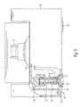
Fig. 3 in belastetem Zustand; - Fig. 5
- eine weitere Ausführungsform eines erfindungsgemäßen Dentalgeräts in teilweiser aufgebrochener Darstellung; und
- Fig. 6
- eine Ausschnittsvergrößerung zu
Fig. 5 .
- Fig. 1
- a schematic view of a frame with motor and mixing arm as part of the dental device according to the invention;
- Fig. 2
- a sectional view of a bearing point of a dental device according to the invention;
- Fig. 3
- a section through a stand according to the invention in unloaded condition;
- Fig. 4
- the stand according to
Fig. 3 in loaded condition; - Fig. 5
- a further embodiment of a dental device according to the invention in a partially broken-away representation; and
- Fig. 6
- an enlarged detail too
Fig. 5 ,
Die in
Der Mischarm 16 ist über Federelemente 18 an dem im Wesentlichen U-förmigen Rahmen 12 gelagert. In dem dargestellten Ausführungsbeispiel weist der Motor hierzu nicht dargestellte Zapfen auf, die in V-förmigen Ausschnitten 20 ruhen, die in den Federelementen 18 vorgesehen sind. Die Federelemente 18 sind in passende Ausnehmungen der Seitenschenkel des Rahmens 12 eingeschnappt, so dass der Motor 14 insofern federnd an dem Rahmen 12 aufgehängt ist.The mixing
Der Motor 14 weist ferner eine Schwungscheibe 22 mit einer asymmetrischen Masse auf, die als Massenausgleich für die Bewegungen des Mischarms 16 dient, wobei hierzu entsprechende Bohrungen 24 in der Schwungscheibe 22 asymmetrisch vorgesehen sind.The
Der Rahmen 12 ist an vier Lagerstellen an einem Gehäuse des Dentalgeräts 10 gelagert, von denen drei Lagerstellen ersichtlich sind. Jede Lagerstelle 30 weist ein oberes Dämpfungselement 32 und ein unteres Dämpfungselement 34 auf. In dem dargestellten Ausführungsbeispiel ist das obere Dämpfungselement 32 mit seinem oberen Ende an einer nach unten weisenden Anschlagfläche des Gehäuses abgestützt, und das untere Dämpfungselement 34 ist an seinem unteren Ende an einer nach oben weisenden Anschlagfläche des Gehäuses abgestützt. Das obere Dämpfungselement 32 ist je weicher als das untere Dämpfungselement 34, das je zusätzlich das Gewicht des Motors, des Mischarms und des Rahmens tragen muss.The
Wie aus
Die Dämpfungselemente 32 und 34 sind von einem Gehäuse 44 eingespannt gehalten. Das Gehäuse 44 weist einen oberen Teil 46 auf, der eine topfförmige Ausnehmung 48 aufweist, in dem das obere Ende des Dämpfungselements 32 geführt ist. Dort wird insofern eine nach unten weisende Anschlagfläche 50 des Gehäuses ausgebildet. Zwischen dem oberen Teil 46 der Gehäuses und dem Gehäuse 44 im übrigen ist zudem eine Verschraubung 47 angebracht, die beide Teile gegeneinander verspannt und hierdurch die Dämpfungselemente 32 und 34 unter Vorspannung setzt.The damping
Als Teil des Gehäuses 44 ist zudem ein Standfuß 52 realisiert, der in einer Bodenplatte 54 des Gehäuses 44 gelagert ist, und zwar über eine Nut 56, die umlaufend an dem Standfuß 52 ausgebildet ist.As part of the
Der Standfuß 52 bildet eine nach oben weisende Anschlagfläche 58 des Gehäuses, die das Dämpfungselement 34 abstützt. Dort ist zudem eine Seitenführung über einen Mittelzapfen 60 gebildet, der sich von dem Standfuß 52 ausgehend in die Durchgangsbohrung hinein erstreckt.The base 52 forms an upwardly facing
Beim Einfedern durch Belastung des Rahmens 12 nach unten wird das untere Dämpfungselement 32 komprimiert und verdickt sich hinsichtlich seiner Wandstärke insofern, während das obere Dämpfungselement leicht entspannt wird. Die Entspannung erfolgt jedoch lediglich in einem solchen Maße, dass stets eine Anlage an der oberen Anschlagfläche 50 gewährleistet ist. Insofern wird durch das Zusammenwirken der Teile 46 und 52 des Gehäuses 44 eine Vorspannung auf die Dämpfungselemente 32 und 34 eingeleitet und der Rahmen 32 unter Spannung zwischen diesen gehalten.During compression by loading the
Der Standfuß 52 wird durch die zusätzliche Gewichtsbelastung im Bereich der Anschlagfläche 53 belastet. Dort ist im auswärtigen Bereich eine ringförmige Aufstandsfläche 62 vorgesehen, die sich um eine nach der Art einer negativen Kalotte gebildeten Mulde 64 erstreckt. Im inneren Bereich der Anschlagfläche 58 erstreckt sich insofern die Mulde 64.The
Die in
Andererseits wird durch die zusätzliche Belastung des Rahmens auch der Gegendruck über das Gewicht insgesamt erhöht, der insofern im Bereich der Nut 56 angreift. Insofern entsteht ein entgegenwirkender Druck um den Drehpunkt 70, und bei richtiger Auslegung werden diese beiden Momente so kompensiert, dass auch bei zusätzlicher Belastung der Standfuß nicht zusätzlich einfedert, der Abstand zwischen der Unterlage 72 und der Nut 56 und damit dem Gehäuse 44 also insofern konstant bleibt.On the other hand, the total load on the weight is increased in total by the additional burden of the frame, the extent that engages in the region of the
Eine weitere Ausführungsform eines erfindungsgemäßen Dentalgerätes ist aus
Zwischen dem oberen Teil 46 der Gehäuses und dem Gehäuse 44 im übrigen ist hier im Bereich der Bodenplatte eine Verschraubung 47 angebracht, die beide Teile gegeneinander verspannt und hierdurch die Dämpfungselemente 32 und 34 unter Druck setzt.Between the
Die Abstandsfestlegung ist auch aus
Claims (15)
Applications Claiming Priority (1)
| Application Number | Priority Date | Filing Date | Title |
|---|---|---|---|
| DE102008008919A DE102008008919B4 (en) | 2008-02-13 | 2008-02-13 | Dental device |
Publications (3)
| Publication Number | Publication Date |
|---|---|
| EP2090262A2 true EP2090262A2 (en) | 2009-08-19 |
| EP2090262A3 EP2090262A3 (en) | 2009-09-16 |
| EP2090262B1 EP2090262B1 (en) | 2013-05-15 |
Family
ID=40627293
Family Applications (1)
| Application Number | Title | Priority Date | Filing Date |
|---|---|---|---|
| EP09152063.5A Active EP2090262B1 (en) | 2008-02-13 | 2009-02-04 | Dental device |
Country Status (3)
| Country | Link |
|---|---|
| US (1) | US8177416B2 (en) |
| EP (1) | EP2090262B1 (en) |
| DE (1) | DE102008008919B4 (en) |
Citations (1)
| Publication number | Priority date | Publication date | Assignee | Title |
|---|---|---|---|---|
| DE9309794U1 (en) | 1993-07-01 | 1994-11-10 | Harnisch & Rieth Maschbau | Vibrating device for the dental sector |
Family Cites Families (7)
| Publication number | Priority date | Publication date | Assignee | Title |
|---|---|---|---|---|
| JPS4856894U (en) * | 1971-10-29 | 1973-07-20 | ||
| US4125335A (en) * | 1977-02-03 | 1978-11-14 | Blume Horst K | Agitator system |
| DE3106690A1 (en) * | 1981-02-23 | 1982-09-09 | Klöckner-Humboldt-Deutz AG, 5000 Köln | RUBBER SPRING FOR THE ELASTIC STORAGE OF MACHINES |
| DE3919775C2 (en) * | 1989-06-16 | 1994-09-01 | Daimler Benz Ag | Support bearing |
| JPH09126274A (en) * | 1995-10-27 | 1997-05-13 | Ishikawajima Harima Heavy Ind Co Ltd | Vibration control structure for space gear |
| IL166505A0 (en) * | 2002-08-01 | 2006-01-15 | Bertin Technologies Sa | Device for fast vibration of tubes containing samples |
| DE202006019709U1 (en) * | 2006-12-28 | 2007-03-08 | Wang, Shu-Lung, San-Chung | Mixer for amalgam, for dental cavity fillings, has a damper system with adjustable springs over and under a lateral holding plate to absorb oscillations at the holding frame |
-
2008
- 2008-02-13 DE DE102008008919A patent/DE102008008919B4/en active Active
-
2009
- 2009-02-04 EP EP09152063.5A patent/EP2090262B1/en active Active
- 2009-02-13 US US12/378,492 patent/US8177416B2/en active Active
Patent Citations (1)
| Publication number | Priority date | Publication date | Assignee | Title |
|---|---|---|---|---|
| DE9309794U1 (en) | 1993-07-01 | 1994-11-10 | Harnisch & Rieth Maschbau | Vibrating device for the dental sector |
Also Published As
| Publication number | Publication date |
|---|---|
| US8177416B2 (en) | 2012-05-15 |
| EP2090262A3 (en) | 2009-09-16 |
| EP2090262B1 (en) | 2013-05-15 |
| US20090201762A1 (en) | 2009-08-13 |
| DE102008008919A1 (en) | 2009-08-27 |
| DE102008008919B4 (en) | 2011-07-21 |
Similar Documents
| Publication | Publication Date | Title |
|---|---|---|
| EP0544175B1 (en) | Machine base | |
| DE60105817T2 (en) | METHOD FOR VIBRATING VIBRATIONS AND METHOD FOR STORING THE DEVICE | |
| EP3017738B1 (en) | Stand of a device, in particular a table-top kitchen appliance | |
| DE2953729A1 (en) | Mount to absorb shocks | |
| DE2051626A1 (en) | Device for generating a vibration counterforce | |
| DE69918114T2 (en) | RITZ TOOL | |
| DE10353907B4 (en) | Vibration isolation device, in particular for earthquake protection of buildings | |
| DE69915065T2 (en) | RICE NEEDLE | |
| EP2208693A2 (en) | Linear vibration feeder | |
| DE1965583A1 (en) | Anti-vibration support | |
| EP2090262B1 (en) | Dental device | |
| EP2410200B1 (en) | Base, in particular for a table kitchen appliance | |
| DE3938383C1 (en) | ||
| DE102008015129B3 (en) | Flush-mounted switch, has wall compensating spring tongues overlapping bottom edge of cover frame, where spring tongues are compressed during pressurization of compensators before switch engages into stable switch position | |
| DE10312977A1 (en) | Spring element for transmission components, valves, etc. in motor vehicles has contact sections and connecting elastic bridging sections for increased damping of vibrations | |
| DE102006041434B4 (en) | Schwingungsisolatiosvorrichtung | |
| EP2659810A1 (en) | Stand of a device, in particular a table-top kitchen appliance | |
| EP0457058B1 (en) | High voltage apparatus | |
| EP3698067B1 (en) | Vibration absorber, in particular for a control cabinet | |
| WO2009024329A1 (en) | Oscillating stool | |
| DE10064881B4 (en) | Foot bearings for height-adjustable feet of a support frame for baths and shower trays | |
| EP2870903B1 (en) | Stand of a table kitchen appliance | |
| DE2014999A1 (en) | Buffer device for regulating vibrations, noises and shocks | |
| DE19535580C2 (en) | Dynamically mounted vehicle seat | |
| DE2309950C3 (en) | Vibration-damping machine base |
Legal Events
| Date | Code | Title | Description |
|---|---|---|---|
| PUAI | Public reference made under article 153(3) epc to a published international application that has entered the european phase |
Free format text: ORIGINAL CODE: 0009012 |
|
| PUAL | Search report despatched |
Free format text: ORIGINAL CODE: 0009013 |
|
| AK | Designated contracting states |
Kind code of ref document: A2 Designated state(s): AT BE BG CH CY CZ DE DK EE ES FI FR GB GR HR HU IE IS IT LI LT LU LV MC MK MT NL NO PL PT RO SE SI SK TR |
|
| AX | Request for extension of the european patent |
Extension state: AL BA RS |
|
| AK | Designated contracting states |
Kind code of ref document: A3 Designated state(s): AT BE BG CH CY CZ DE DK EE ES FI FR GB GR HR HU IE IS IT LI LT LU LV MC MK MT NL NO PL PT RO SE SI SK TR |
|
| AX | Request for extension of the european patent |
Extension state: AL BA RS |
|
| 17P | Request for examination filed |
Effective date: 20091010 |
|
| 17Q | First examination report despatched |
Effective date: 20091109 |
|
| AKX | Designation fees paid |
Designated state(s): AT BE BG CH CY CZ DE DK EE ES FI FR GB GR HR HU IE IS IT LI LT LU LV MC MK MT NL NO PL PT RO SE SI SK TR |
|
| GRAP | Despatch of communication of intention to grant a patent |
Free format text: ORIGINAL CODE: EPIDOSNIGR1 |
|
| GRAS | Grant fee paid |
Free format text: ORIGINAL CODE: EPIDOSNIGR3 |
|
| GRAA | (expected) grant |
Free format text: ORIGINAL CODE: 0009210 |
|
| AK | Designated contracting states |
Kind code of ref document: B1 Designated state(s): AT BE BG CH CY CZ DE DK EE ES FI FR GB GR HR HU IE IS IT LI LT LU LV MC MK MT NL NO PL PT RO SE SI SK TR |
|
| REG | Reference to a national code |
Ref country code: GB Ref legal event code: FG4D Free format text: NOT ENGLISH Ref country code: CH Ref legal event code: EP |
|
| REG | Reference to a national code |
Ref country code: CH Ref legal event code: NV Representative=s name: KELLER AND PARTNER PATENTANWAELTE AG, CH |
|
| REG | Reference to a national code |
Ref country code: AT Ref legal event code: REF Ref document number: 611724 Country of ref document: AT Kind code of ref document: T Effective date: 20130615 |
|
| REG | Reference to a national code |
Ref country code: IE Ref legal event code: FG4D Free format text: LANGUAGE OF EP DOCUMENT: GERMAN |
|
| REG | Reference to a national code |
Ref country code: DE Ref legal event code: R096 Ref document number: 502009007084 Country of ref document: DE Effective date: 20130711 |
|
| REG | Reference to a national code |
Ref country code: SE Ref legal event code: TRGR |
|
| REG | Reference to a national code |
Ref country code: LT Ref legal event code: MG4D |
|
| REG | Reference to a national code |
Ref country code: NL Ref legal event code: VDEP Effective date: 20130515 |
|
| PG25 | Lapsed in a contracting state [announced via postgrant information from national office to epo] |
Ref country code: PT Free format text: LAPSE BECAUSE OF FAILURE TO SUBMIT A TRANSLATION OF THE DESCRIPTION OR TO PAY THE FEE WITHIN THE PRESCRIBED TIME-LIMIT Effective date: 20130916 Ref country code: FI Free format text: LAPSE BECAUSE OF FAILURE TO SUBMIT A TRANSLATION OF THE DESCRIPTION OR TO PAY THE FEE WITHIN THE PRESCRIBED TIME-LIMIT Effective date: 20130515 Ref country code: GR Free format text: LAPSE BECAUSE OF FAILURE TO SUBMIT A TRANSLATION OF THE DESCRIPTION OR TO PAY THE FEE WITHIN THE PRESCRIBED TIME-LIMIT Effective date: 20130816 Ref country code: IS Free format text: LAPSE BECAUSE OF FAILURE TO SUBMIT A TRANSLATION OF THE DESCRIPTION OR TO PAY THE FEE WITHIN THE PRESCRIBED TIME-LIMIT Effective date: 20130915 Ref country code: ES Free format text: LAPSE BECAUSE OF FAILURE TO SUBMIT A TRANSLATION OF THE DESCRIPTION OR TO PAY THE FEE WITHIN THE PRESCRIBED TIME-LIMIT Effective date: 20130826 Ref country code: SI Free format text: LAPSE BECAUSE OF FAILURE TO SUBMIT A TRANSLATION OF THE DESCRIPTION OR TO PAY THE FEE WITHIN THE PRESCRIBED TIME-LIMIT Effective date: 20130515 Ref country code: LT Free format text: LAPSE BECAUSE OF FAILURE TO SUBMIT A TRANSLATION OF THE DESCRIPTION OR TO PAY THE FEE WITHIN THE PRESCRIBED TIME-LIMIT Effective date: 20130515 Ref country code: NO Free format text: LAPSE BECAUSE OF FAILURE TO SUBMIT A TRANSLATION OF THE DESCRIPTION OR TO PAY THE FEE WITHIN THE PRESCRIBED TIME-LIMIT Effective date: 20130815 |
|
| PG25 | Lapsed in a contracting state [announced via postgrant information from national office to epo] |
Ref country code: HR Free format text: LAPSE BECAUSE OF FAILURE TO SUBMIT A TRANSLATION OF THE DESCRIPTION OR TO PAY THE FEE WITHIN THE PRESCRIBED TIME-LIMIT Effective date: 20130515 Ref country code: BG Free format text: LAPSE BECAUSE OF FAILURE TO SUBMIT A TRANSLATION OF THE DESCRIPTION OR TO PAY THE FEE WITHIN THE PRESCRIBED TIME-LIMIT Effective date: 20130815 Ref country code: PL Free format text: LAPSE BECAUSE OF FAILURE TO SUBMIT A TRANSLATION OF THE DESCRIPTION OR TO PAY THE FEE WITHIN THE PRESCRIBED TIME-LIMIT Effective date: 20130515 |
|
| PG25 | Lapsed in a contracting state [announced via postgrant information from national office to epo] |
Ref country code: LV Free format text: LAPSE BECAUSE OF FAILURE TO SUBMIT A TRANSLATION OF THE DESCRIPTION OR TO PAY THE FEE WITHIN THE PRESCRIBED TIME-LIMIT Effective date: 20130515 |
|
| PG25 | Lapsed in a contracting state [announced via postgrant information from national office to epo] |
Ref country code: DK Free format text: LAPSE BECAUSE OF FAILURE TO SUBMIT A TRANSLATION OF THE DESCRIPTION OR TO PAY THE FEE WITHIN THE PRESCRIBED TIME-LIMIT Effective date: 20130515 Ref country code: SK Free format text: LAPSE BECAUSE OF FAILURE TO SUBMIT A TRANSLATION OF THE DESCRIPTION OR TO PAY THE FEE WITHIN THE PRESCRIBED TIME-LIMIT Effective date: 20130515 Ref country code: CZ Free format text: LAPSE BECAUSE OF FAILURE TO SUBMIT A TRANSLATION OF THE DESCRIPTION OR TO PAY THE FEE WITHIN THE PRESCRIBED TIME-LIMIT Effective date: 20130515 Ref country code: EE Free format text: LAPSE BECAUSE OF FAILURE TO SUBMIT A TRANSLATION OF THE DESCRIPTION OR TO PAY THE FEE WITHIN THE PRESCRIBED TIME-LIMIT Effective date: 20130515 |
|
| PG25 | Lapsed in a contracting state [announced via postgrant information from national office to epo] |
Ref country code: NL Free format text: LAPSE BECAUSE OF FAILURE TO SUBMIT A TRANSLATION OF THE DESCRIPTION OR TO PAY THE FEE WITHIN THE PRESCRIBED TIME-LIMIT Effective date: 20130515 Ref country code: RO Free format text: LAPSE BECAUSE OF FAILURE TO SUBMIT A TRANSLATION OF THE DESCRIPTION OR TO PAY THE FEE WITHIN THE PRESCRIBED TIME-LIMIT Effective date: 20130515 |
|
| PLBE | No opposition filed within time limit |
Free format text: ORIGINAL CODE: 0009261 |
|
| STAA | Information on the status of an ep patent application or granted ep patent |
Free format text: STATUS: NO OPPOSITION FILED WITHIN TIME LIMIT |
|
| 26N | No opposition filed |
Effective date: 20140218 |
|
| REG | Reference to a national code |
Ref country code: DE Ref legal event code: R097 Ref document number: 502009007084 Country of ref document: DE Effective date: 20140218 |
|
| BERE | Be: lapsed |
Owner name: IVOCLAR VIVADENT AG Effective date: 20140228 |
|
| PG25 | Lapsed in a contracting state [announced via postgrant information from national office to epo] |
Ref country code: LU Free format text: LAPSE BECAUSE OF FAILURE TO SUBMIT A TRANSLATION OF THE DESCRIPTION OR TO PAY THE FEE WITHIN THE PRESCRIBED TIME-LIMIT Effective date: 20140204 Ref country code: MC Free format text: LAPSE BECAUSE OF FAILURE TO SUBMIT A TRANSLATION OF THE DESCRIPTION OR TO PAY THE FEE WITHIN THE PRESCRIBED TIME-LIMIT Effective date: 20130515 |
|
| REG | Reference to a national code |
Ref country code: IE Ref legal event code: MM4A |
|
| PG25 | Lapsed in a contracting state [announced via postgrant information from national office to epo] |
Ref country code: BE Free format text: LAPSE BECAUSE OF NON-PAYMENT OF DUE FEES Effective date: 20140228 Ref country code: IE Free format text: LAPSE BECAUSE OF NON-PAYMENT OF DUE FEES Effective date: 20140204 |
|
| REG | Reference to a national code |
Ref country code: CH Ref legal event code: PCAR Free format text: NEW ADDRESS: EIGERSTRASSE 2 POSTFACH, 3000 BERN 14 (CH) |
|
| REG | Reference to a national code |
Ref country code: FR Ref legal event code: PLFP Year of fee payment: 8 |
|
| PG25 | Lapsed in a contracting state [announced via postgrant information from national office to epo] |
Ref country code: MT Free format text: LAPSE BECAUSE OF FAILURE TO SUBMIT A TRANSLATION OF THE DESCRIPTION OR TO PAY THE FEE WITHIN THE PRESCRIBED TIME-LIMIT Effective date: 20130515 |
|
| PG25 | Lapsed in a contracting state [announced via postgrant information from national office to epo] |
Ref country code: CY Free format text: LAPSE BECAUSE OF FAILURE TO SUBMIT A TRANSLATION OF THE DESCRIPTION OR TO PAY THE FEE WITHIN THE PRESCRIBED TIME-LIMIT Effective date: 20130515 |
|
| PG25 | Lapsed in a contracting state [announced via postgrant information from national office to epo] |
Ref country code: HU Free format text: LAPSE BECAUSE OF FAILURE TO SUBMIT A TRANSLATION OF THE DESCRIPTION OR TO PAY THE FEE WITHIN THE PRESCRIBED TIME-LIMIT; INVALID AB INITIO Effective date: 20090204 Ref country code: TR Free format text: LAPSE BECAUSE OF FAILURE TO SUBMIT A TRANSLATION OF THE DESCRIPTION OR TO PAY THE FEE WITHIN THE PRESCRIBED TIME-LIMIT Effective date: 20130515 |
|
| REG | Reference to a national code |
Ref country code: DE Ref legal event code: R079 Ref document number: 502009007084 Country of ref document: DE Free format text: PREVIOUS MAIN CLASS: A61C0005060000 Ipc: A61C0005600000 |
|
| REG | Reference to a national code |
Ref country code: FR Ref legal event code: PLFP Year of fee payment: 9 |
|
| REG | Reference to a national code |
Ref country code: FR Ref legal event code: PLFP Year of fee payment: 10 |
|
| PG25 | Lapsed in a contracting state [announced via postgrant information from national office to epo] |
Ref country code: MK Free format text: LAPSE BECAUSE OF FAILURE TO SUBMIT A TRANSLATION OF THE DESCRIPTION OR TO PAY THE FEE WITHIN THE PRESCRIBED TIME-LIMIT Effective date: 20130515 |
|
| REG | Reference to a national code |
Ref country code: CH Ref legal event code: PFA Owner name: IVOCLAR VIVADENT AG, LI Free format text: FORMER OWNER: IVOCLAR VIVADENT AG, LI |
|
| PGFP | Annual fee paid to national office [announced via postgrant information from national office to epo] |
Ref country code: FR Payment date: 20230104 Year of fee payment: 15 Ref country code: CH Payment date: 20230307 Year of fee payment: 15 Ref country code: AT Payment date: 20230109 Year of fee payment: 15 |
|
| PGFP | Annual fee paid to national office [announced via postgrant information from national office to epo] |
Ref country code: SE Payment date: 20230109 Year of fee payment: 15 Ref country code: IT Payment date: 20230127 Year of fee payment: 15 Ref country code: GB Payment date: 20230109 Year of fee payment: 15 Ref country code: DE Payment date: 20230105 Year of fee payment: 15 |
|
| P01 | Opt-out of the competence of the unified patent court (upc) registered |
Effective date: 20230607 |
|
| PGFP | Annual fee paid to national office [announced via postgrant information from national office to epo] |
Ref country code: AT Payment date: 20240109 Year of fee payment: 16 |