EP2092955B1 - Leitungen zur Schrittstimulierung und/oder Überwachung des Herzens von den Koronarvenen aus - Google Patents
Leitungen zur Schrittstimulierung und/oder Überwachung des Herzens von den Koronarvenen aus Download PDFInfo
- Publication number
- EP2092955B1 EP2092955B1 EP09161205.1A EP09161205A EP2092955B1 EP 2092955 B1 EP2092955 B1 EP 2092955B1 EP 09161205 A EP09161205 A EP 09161205A EP 2092955 B1 EP2092955 B1 EP 2092955B1
- Authority
- EP
- European Patent Office
- Prior art keywords
- lead
- electrode
- electrodes
- lead body
- recited
- Prior art date
- Legal status (The legal status is an assumption and is not a legal conclusion. Google has not performed a legal analysis and makes no representation as to the accuracy of the status listed.)
- Expired - Lifetime
Links
Images


Classifications
-
- A—HUMAN NECESSITIES
- A61—MEDICAL OR VETERINARY SCIENCE; HYGIENE
- A61N—ELECTROTHERAPY; MAGNETOTHERAPY; RADIATION THERAPY; ULTRASOUND THERAPY
- A61N1/00—Electrotherapy; Circuits therefor
- A61N1/02—Details
- A61N1/04—Electrodes
- A61N1/05—Electrodes for implantation or insertion into the body, e.g. heart electrode
- A61N1/056—Transvascular endocardial electrode systems
- A61N1/057—Anchoring means; Means for fixing the head inside the heart
-
- A—HUMAN NECESSITIES
- A61—MEDICAL OR VETERINARY SCIENCE; HYGIENE
- A61N—ELECTROTHERAPY; MAGNETOTHERAPY; RADIATION THERAPY; ULTRASOUND THERAPY
- A61N1/00—Electrotherapy; Circuits therefor
- A61N1/02—Details
- A61N1/04—Electrodes
- A61N1/05—Electrodes for implantation or insertion into the body, e.g. heart electrode
- A61N1/056—Transvascular endocardial electrode systems
- A61N2001/0585—Coronary sinus electrodes
Definitions
- the present invention relates to the field of leads for correcting arrhythmias of the heart. More particularly, this invention relates to leads for pacing and/or sensing the heart from the coronary vasculature.
- a cardiac pacing system includes a battery powered pulse generator and one or more leads for delivering pulses to the heart.
- Current pulse generators include electronic circuitry for determining the nature of an irregular rhythm, commonly referred to as arrhythmia, and for timing the delivery of a pulse for a particular purpose.
- the pulse generator is typically implanted into a subcutaneous pocket made in the wall of the chest. Insulated wires called leads attached to the pulse generator are routed subcutaneously from the pocket to the shoulder or neck where the leads enter a major vein, usually the subclavian vein. The leads are then routed into the site of pacing, usually a chamber of the heart.
- the leads are electrically connected to the pulse generators on one end and are electrically connected to the heart on the other end. Electrodes on the leads provide the electrical connection of the lead to the heart. The leads deliver the electrical discharges from the pulse generator to the heart.
- the electrodes are typically arranged on a lead body in two ways or categories.
- a pair of electrodes which form a single electrical circuit i.e., one electrode is positive and one electrode is negative
- the bipolar arrangement of electrodes requires two insulated wires positioned within the lead.
- this arrangement is known as a unipolar arrangement.
- the unipolar arrangement of electrodes requires one insulated wire positioned within the lead.
- a common practice for a patient requiring multi-site pacing within one or more chambers of the heart would be to provide two separate and different leads attached to the particular chamber of the heart. One lead would be implanted at one site in the chamber. Another lead would be implanted at another site in the same chamber, or another chamber.
- the single chamber of the heart receiving multi-site pacing would be the right atrium.
- two separate leads is undesirable for many reasons. Among these are the complexity of and time required for the implantation procedure for implanting two leads as compared to that of the procedure for implanting one lead.
- two leads may mechanically interact with one another after implantation which can result in dislodgement of one or both of the leads. In vivo mechanical interaction of the leads may also cause abrasion of the insulative layer along the lead which can result in electrical failure of one or both of the leads.
- Another problem is that as more leads are implanted in the heart, the ability to add leads is reduced. If the patient's condition changes over time, the ability to add leads is restricted. Two separate leads also increase the risk of infection and may result in additional health care costs associated with reimplantation and follow-up.
- the heart functions with two sides.
- the right side of the heart receives blood from the body and pumps it into the lungs to exchange gases.
- the left side of the heart receives the oxygenated blood from the lungs and pumps it to the brain and throughout the body.
- endocardial pacing and defibrillation leads are positioned within the right chambers of the heart.
- a major reason that this is typically practiced is that the risk of severe cerebral accidents during endocardial, left heart procedures is greater than that encountered during endocardial right side heart procedures.
- it is safer for the patient to position leads within the right heart numerous difficulties are encountered when it is desired to sense and pace the left heart endocardially.
- Document EP-A-0 919 254 discloses a cardiac pacing lead to be placed within the coronary sinus.
- This lead comprises a proximal end, a distal end a stiff portion located between the two ends; electrodes are distributed along the length of the lead.
- the distal end is formed as a blunt, tapered, flexible tip to enhance manoeuvrability through the tortuous cardiac veins.
- the stiff portion is designed so as to allow the electrodes to be wedged into position against the wall of the vasculature.
- both right atrial and left atrial contact may be made. Electrical contact with the tissues is ensured due to the stiffness of the lead body.
- Document US-A-5 476 498 discloses a cardiac pacing lead to be placed within the coronary sinus for pacing of the left atrium.
- This lead comprises a tapered tip portion and a helical portion for intimate contact with the wall of the coronary sinus.
- a single elongated electrode is wound around the entire length of the helical portion.
- Document US-A-5 871 531 shows a lead for implantation in the coronary sinus having a duel tapered spiral electrode at a distal end thereof.
- a lead is provided herein which includes a lead body having a proximal portion and a distal portion and an intermediate portion therebetween.
- the lead further includes at least one electrode coupled with the lead body, where the lead body is adapted to carry signals to and from the at least one electrode, and a connector located at a proximal end of the lead.
- a portion of the distal portion of the lead body has a preformed radius of curvature substantially the same as or slightly smaller than a coronary sinus and geometrically shaped to hug a wall of the coronary sinus.
- the electrode includes a first electrode associated with the distal portion of the lead body, the first electrode including a first electrode contact area, and a second electrode associated with the distal portion of the lead body, the second electrode including a second electrode contact area, the distal portion of the lead constructed and arranged to urge the first and second electrodes toward a wall of a passage, and optionally the first electrode and the second electrode are spaced about 1 - 5 mm apart.
- the lead further includes at least one atrial pacing electrode.
- the distal portion of the lead body further includes at least one arched tine located opposite the first electrode, and at least one arched tine located opposite the second electrode, where the tines are constructed and arranged to urge the electrode contact area of the first and second electrodes toward a wall of a passage.
- the distal portion of the lead body further includes a double bias configuration constructed and arranged to urge the at least one electrode toward a wall of a passage.
- the first electrode and/or the second electrode is optionally partially masked and further comprises an electrical contact portion constructed and arranged to contact a wall of a passage.
- the lead body further includes an external steroid collar disposed in close proximity to one electrode, or at least a portion of the lead body comprises a shape memory material.
- the distal portion of the lead body has a tapered outer diameter, and the outer diameter includes a first diameter at the intermediate portion and a second diameter at the distal portion, and the first diameter is greater than the second diameter.
- the distal portion of the lead body further includes a helical portion having the at least one electrode thereon, the helical portion is constructed and arranged to urge the at least one electrode toward a wall of a passage, and optionally a plurality of electrodes are disposed on the helical portion, and the plurality of electrodes are spaced about 120 degrees apart along the helical portion.
- the lead further includes apical electrodes, mid ventricular electrodes, and ventricular electrodes that are coupled with the lead body.
- the distal portion of the lead body further includes at least one arched tine located opposite the at least one electrode, where the at least one arched tine optionally comprises a pliable, thin arched tine which extends from a first end to a second end, and the first end and the second end are coupled with the lead body.
- a lead which includes a lead body having a proximal portion and a distal portion and an intermediate portion therebetween.
- the lead further includes at least one electrode coupled with the lead body, where the lead body is adapted to carry signals to and from the at least one electrode, and a connector located at a proximal end of the lead.
- the distal portion of the lead body has a helical portion that is adapted to be implanted within a passage, and at least one electrode is coupled with the helical portion of the lead body.
- a plurality of electrodes are disposed on the helical portion, and the plurality of electrodes are spaced about 120 degrees apart along the helical portion.
- the lead further includes apical electrodes, mid ventricular electrodes, and ventricular electrodes on the helical portion.
- at least a portion of the lead body comprises a shape memory material.
- the distal portion of the lead body has a tapered outer diameter, and the outer diameter includes a first diameter at the intermediate portion and a second diameter at the distal portion, and the first diameter is greater than the second diameter.
- a lead assembly in another embodiment, includes a lead body adapted to carry electrical signals, where the lead body has a proximal end and a distal end, and an intermediate portion therebetween, and a connector is located at the proximal end of the lead body. At least one conductor disposed within the lead body, and the lead body has at least one preformed biased portion at an intermediate portion of the lead body.
- the lead further includes an unbiased, flexible tapered portion disposed between the biased portion and the distal end of the lead body, and the tapered portion distal to the biased portion is substantially more flexible than the biased portion.
- the lead further includes at least one electrode coupled with at least one conductor.
- the unbiased, flexible tapered portion terminates at the distal end of the lead body.
- the conductor forms an inner lumen therein, and the inner lumen is isodiametric.
- none of the conductors extend to the distal end of the lead body, where optionally the conductor terminates within the unbiased, flexible, tapered portion of the lead body.
- the biased portion has a helical shape, and optionally electrodes are disposed along the helical shape, wherein the electrodes on the helical shape are spaced 120 degrees apart.
- the lead includes, in another option, radiopaque material molded within material forming the unbiased, flexible, tapered portion.
- the above described leads advantageously provide the ability to sense and pace the heart using leads positioned within the cardiac vasculature, and further the leads provide the ability to pace and/or sense the left heart. It has been found that by placing a therapeutic lead near the atrium, but not in the atrium, higher amplitude electrograms may be detected as compared to a standard endocardial lead. Further, it has been found that left sided pacing may help suppress atrial arrhythmias, particularly those originating near the left atrium. Still further, it has been found that the ability to critically control the timing between pacing the atria and ventricles of the heart is of utility in optimizing pacing therapies.
- the leads described herein involve geometries that utilize the shape of the local vasculature, the shape of the heart, or both, to help insure that an optimally positioned lead will remain in that position well beyond the time of implant.
- the lead designs discussed herein yield reliable and optimal performance in sensing and pacing of the heart.
- New coronary lead configurations are provided which can provide dual chamber pacing and/or defibrillation on a single lead body.
- the lead advantageously allows for effective use of a biased portion on a lead body in combination with an atraumatic tip assembly.
- the biased portion allows for gentle and effective forces against passage walls enabling the lead to be positionally maintained therein.
- the biased portion ensures the electrode is placed up against the passage wall with sufficient force.
- the spacing of the electrodes along the biased portion provides for an increased opportunity for the electrode to be placed against the passage wall.
- the atraumatic tip assembly is extremely flexible, relative to the biased portion, which allows for improved maneuverability of the lead through tortuous vasculature, and allows for the lead to be implanted more easily and quickly than conventional leads.
- the flexible tapered portion of the atraumatic tip assembly allows for the guidewire or stylet, if used, to better guide the lead without interference from the biased portion.
- Figure 1A is a side view of one example of a coronary vein lead 100.
- the lead 100 has a proximal end 102 and a distal end 104 and includes a connector terminal 110 and a lead body 120.
- the lead 100 attaches to a pulse sensor and generator 140.
- the lead 100 is constructed and arranged for insertion into the coronary sinus, as discussed further below.
- the lead body 120 has a number of electrodes 122 in its distal end 104 which is implanted in a coronary vein.
- the connector terminal 110 electrically connects the various electrodes and conductors within the lead body 120 to a pulse sensor and generator 140.
- the pulse sensor and generator 140 contains electronics to sense various pulses of the heart and also produce pulsing signals for delivery to the heart.
- the pulse sensor and generator 140 also contains electronics and software necessary to detect certain types of arrhythmias and to correct for them.
- the lead 100 operates similarly to a bipolar lead having positive and negative portions of a circuit located in the lead body 120. It should be noted that this lead may also be made a unipolar lead.
- one electrode or both electrodes of the lead body 120 can be pacing/sensing electrodes, or one electrode can be a pacing/sensing electrode and the anode can be the pulse generator.
- the lead body 120 is a tubing material formed from a polymer biocompatible for implantation, and preferably the tubing is made from a silicone rubber polymer.
- the lead body 120 may be made of a biocompatible material having shape memory characteristics such that it will return to its preformed shape once implanted and a stylet or guidewire is removed.
- An example of such a material is polyether polyurethane.
- the lead body 120 optionally has portions which have shape memory characteristics, comprising either a shape memory polymer or a shape memory metal.
- the lead body contains several electrical conductors.
- the electrical conductors are made of a highly conductive, highly corrosion-resistant material.
- the electrical conductors carry current and signals between the pulse sensor and generator 140 and the electrodes located at the distal end 104 of the lead 100. Electrical conductors are shown, for example, at 472 and 473 of Figures 4B and 4C , and at 672 and 673 of Figures 6C , 6E and 6G .
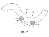
- the lead body 120 has a helical portion 130 at the distal end 104. After implantation, the helical portion 130 will be located in a coronary vein, as shown, for example, in Figure 1B .
- a coronary vein 124 is shown which includes a free wall 126 and a myocardial wall 128. The free wall 126 is disposed away from the heart 125, and the myocardial wall 128 abuts the heart 125.
- the helical portion 130 of the lead body 120 is optionally made of a biocompatible material having shape memory characteristics such that it will return to its preformed helical shape once implanted and a stylet or guidewire is removed.
- a biocompatible material having shape memory characteristics such that it will return to its preformed helical shape once implanted and a stylet or guidewire is removed.
- An example of such a material is polyether polyurethane.
- the lead body may have portions which have shape memory characteristics, comprising either a shape memory polymer or a shape memory metal.
- the diameter of the helix is about .25cm - 2 cm.
- the pitch of the helix ranges from .5 cm - 2.5 cm.
- the helical portion 130 includes electrodes 122.
- the electrodes 122 are evenly spaced at about 120 degrees apart, which increases the opportunity for the electrodes 122 to make contact with the myocardial wall 128. In a further option, pairs of electrodes 122 are evenly spaced about 120 degrees apart along the lead body 120. The electrodes 122 are electrically coupled with one conductor, or are electrically coupled with separate conductors.
- the helical portion 130 facilitates placement of the electrodes against the myocardial wall 128 of the coronary vein 124 during and/or after implantation.
- the helical shape of the lead 100 provides large lead/vessel wall area interface to produce reliable, long term stability. When implanted, the helical shape of the lead 100 produces subtle lateral forces between the electrodes 122 and myocardial wall 128, resulting in low pacing thresholds.
- the distal end 104 of the lead 100 includes several electrodes 122, and in one example has two electrodes 132, 134.
- the first electrode 132 is generally referred to as the distal electrode.
- a second electrode 134 is located near the distal electrode and proximally thereof and can be used as a counter electrode for electrode 132 or for defibrillation therapy.
- the lead 100 may be generally described as a tachycardia (tachy) lead, although it is not limited thereto.
- the electrodes 132, 134 are of an electrically conductive material such as an alloy of platinum and iridium which is highly conductive and highly resistant to corrosion.
- the electrodes 132, 134 optionally include a passive fixation portion.
- Electrodes 132 and 134 are masked or otherwise insulated on the inside radius 142 of the distal end 104 of the lead 100. This decreases electrode area and provides desired increase in impedance.
- the bipolar electrode pair spacing between electrodes 132 and 134 is shown at line A of Figure 2 to be from about 1-5 mm. With such close electrode spacing, increased rejection of problematic far field (ventricular) signals is accomplished.
- the electrode surfaces 136, 138 are raised beyond the body 120 of the lead 100. Electrodes designed in this fashion increase the chances of achieving intimate tissue-electrode contact thereby resulting in lower thresholds.
- Figure 3A shows an exemplary modification of a coronary vein lead 200 which has a helical distal end 230, where the heart 10, left ventricle 22, right ventricle and apex 24 of the heart 10 are shown.
- the left coronary artery 25 branches into the circumflex artery 26 and the anterior descending artery 27.
- the coronary sinus 28 branches into the coronary branch vein 29. Placing the lead 200 in the coronary branch veins, for example, on the left ventricle has been found to be a suitable means for delivering pacing therapy to patients suffering from congestive heart failure.
- the lead 200 is adapted to be used within the coronary artery 25 and also within the coronary branch vein 29.
- a coronary vein lead 200 with a helical distal portion 230 is shown located in an implanted site.
- the coronary vein lead 200 includes a mid ventricular electrode pair 246 (electrodes 232 and 234).
- the electrodes 232, 234 are shown in intimate contact with the vessel wall 108 of the branch vein 29, where the electrodes 232, 234 contact the myocardial wall, as discussed above.
- the coronary vein lead 200 optionally includes a mid ventricular electrode pair 246 (electrodes 232 and 234) and further optionally includes an apical electrode pair 250 (electrodes 252 and 254).
- the helical portion 230 and the spacing of the electrodes positions the electrodes 232, 234 against the myocardium to reduce pacing thresholds.
- the helix diameter is such that a vein of any size will reduce the diameter of the helix so that at least one electrode will be pressed against the myocardial wall.
- the lead 200 optionally has a fixation mechanism 240, as shown in Figures 3A and 3C .
- Electrodes 232, 234 form a midventricular electrode pair 246 and electrodes 242, 244 form a basal electrode pair 248, so designated by their proximity to a particular region of the heart when the lead 200 is in its implanted site in the heart 10.
- Lead 200 has an apical electrode pair 250 formed of electrodes 252, 254 which have a proximity to the apex 24 of the heart 10 when implanted.
- the portion of the lead 200 including the apical electrode pair 250 optionally includes a helical portion. In another option, instead of pairs, single electrodes, or more than two electrodes can be included in that discussed above.
- the lead 200 has multiple electrodes and conductors, and the electrodes which are the cathodes or anodes are selected depending on the thresholds acquired at each stimulation site. As an example, in a bipolar lead, optimal therapy may be achieved by choosing the tip or ring (such as are shown, for example, at 750 and 734 of Figure 7 ) as cathode or anode depending on the different thresholds. In the example shown at Figures 3A and 3B, multiple electrode capacity is provided in the left ventricular vein. These electrodes are capable of pacing together, or alternatively with only a pair of the electrodes pacing together. Further, the electrodes optionally pace with a delay between them or sequentially.
- a steroid is optionally used to ensure pacing at the cathodal site.
- the steroid is located in close proximity of the cathode electrode, for example, electrode 234, and not in close proximity of the anode electrode.
- the steroid is provided by way of steroid collar 256 loaded with the desired drug which is then time released.
- the steroid collar 256 is external to the lead body 220, and adjacent to the electrode.
- the drug has a very localized effect, thereby requiring close proximity to the cathode. Steroid release in close proximity to the anode electrode is not critical, but may be allowed.
- This placement of the steroid collar 256 ensures that the cathode electrode paces first, and before the anode electrode.
- An example of such a drug is dexamethasone acetate.
- a steroid collar or a steroid coating for example, is provided as a generally cylindrical component adjacent one or both sides of an electrode of any lead described herein.
- Another option for the leads described herein involves the use of local drug elution, for example a steroid, in the vicinity of the electrodes.
- desired low chronic pacing thresholds can be achieved through the local release of at least one pharmacologically active agent. This can be easily accomplished by compounding agents into polymeric components positioned adjacent to the electrodes.
- a pharmaceutical agent typically used in pacing applications is one possessing anti-inflammatory action.
- Dexamethasone, dexamethasone sodium phosphate and dexamethasone acetate have been used in commercially released devices. Other agents with other actions are other options.
- steroidal anti-inflammatory agents other than dexamethasone, nonsteriod anti-inflammatory agents, as well as antiarrhythmic, antibiotic, anticoagulative, thrombolytic and other agents known to improve biocompatibility and/or electrical therapies are optionally used.
- the steroid is released from the interior of an electrode and subsequently delivered directly to the heart tissue contacting the electrode.
- a biocompatible polymer such as silicone
- a steroid substance such as dexamethasone
- molding the polymer-drug matrix into a small component than can finally be positioned within a porous electrode Alternatively, a polymer-drug matrix is molded into a generally cylindrical component that can be subsequently positioned adjacent to one or both sides of a generally cylindrical electrode.
- Another alternative is to apply a thin coating of the polymer-drug matrix to the completed lead body construction in locations consistent with the needed close proximity to the electrode.
- a steroid collar is used, as discussed above.
- the lead is constructed and arranged for fixation in the coronary sinus and has specific biases to facilitate placement and retention in the coronary sinus.
- FIGs 4A a double-bias lead 400 constructed and arranged for fixation in the coronary sinus is shown. It should be noted that the double-bias lead 400 can be combined with examples discussed above and below.
- the lead 400 includes a first bias 402 and a second bias 406, although an additional bias is optionally further provided with the lead 400.
- the first bias 402 is disposed in a direction that is different than the second bias 406.
- a lead 400 including half ring electrodes 432, 434 which are biased against the vessel wall by a biased portion 460 of the lead 400.
- the electrodes 432, 434 are spaced about 10 mm apart along the lead 400, and the length of the biased portion 460 is about 30 mm.
- the lead 400 is constructed and arranged so a first plane including a surface 438 of the electrode 434 is spaced about 10 mm from a second plane including a surface 436 of the electrode 432.
- the lead 400 in one example is an over the wire lead with an open distal end, as shown in Figure 4B .
- the lead 400 has a length which fits within the coronary sinus/great cardiac vein.
- the bias portion 460 pushes the electrode up against the vein wall.
- the bias portion 460 is constructed and arranged to fit within the area of the coronary sinus/great cardiac vein around the mitral valve.
- the lengths and diameters of the coronary sinus/great cardiac vein are shown at Figure 4D .
- the coronary sinus has a length of about 37 mm and the great cardiac vein has a length of about 43 mm, for a combined length of about 80 mm.
- the diameter of the proximal end of the coronary sinus at the thebesian valve is about 10 mm.
- the diameter is about 5 mm.
- the distal portion of the great cardiac vein has a diameter of about 3 mm.
- the mitral valve may have a radius ( R ) between about 9.5 mm-42 mm. In general the radius is about 30 mm.
- the biased lead portion 460 shown at Figure 4A has a radius between about 9.5 mm to about 42 mm. In one example, the biased portion has a radius of about 30 mm.
- the biased portion 460 of lead 400 urges electrodes 432,434 against the vein wall.
- the diameter of the bias portion 460 of lead 400 is between electrodes 432 and 434 is larger than the diameter of the vein to provide a snug fit. In one embodiment the diameter is about 10 mm. Subtle lateral forces on vessel wall produce reliable long term stability. Lateral forces between electrode and vessel wall result in low pacing thresholds.
- the lead 400 has an atraumatic tip 490 having an outer diameter of about 5 French (0.066 inch) and an inner diameter of about 0.038 inch.
- the interior space between coils 472 has a diameter of about 0.018 inch.
- Atraumatic tip 490 in one example comprises silastic tubing extending beyond the coils 472 to avoid bruising the vasculature during implantation therein.
- the transition 476 from a portion of lead body 420 which has two coils to the distal portion having one coil 478 is shown.
- the distal portion 404 has a ring electrode 474.
- the lead has an outer diameter of about 0.067 inch at the point where electrode 474 is located.
- the lead 400 of Figure 4A is designed to be implanted inside the coronary sinus/great cardiac veins (CS/GCV), the size of the lead in relation to the veins is very important.
- the leads described herein are designed to be held in place by wall tension, i.e. by the force of the lead against the heart wall.
- the lead 400 must be small enough to slide into place and not damage the walls by excess forces.
- the lead bias or holding mechanism must not be too small or the lead 400 may become dislodged and fall out.
- the biased portion 460 must not be too long or it will extend into the atrium. Referring to Figure 4D , the length of the coronary sinus and great cardiac veins together is 80 mm.
- the electrode should be placed about 43 mm proximal to the tip.
- the diameter of the vein averages at 10 mm at the os (entrance) and goes down to an average of 3 mm at the end of the great cardiac veins.
- the intended position in the implanted site, or the final lead position is considered in the lead design so that in its final position the lead 400 is wedged or held in the appropriate place.
- the outer diameter of the portion that is being wedged in place would be about 20 to 30 % larger than the inner diameter of the blood vessel.
- the dimension 462 of the biased portion 460 is 10 mm. This would wedge into a portion of the vein that is about 7 mm in diameter, which is near the end of the coronary sinus near the beginning of the great cardiac veins.
- the lead body 420 may be made of a biocompatible material having shape memory characteristics such that it will return to its preformed shape once implanted and a stylet or guidewire is removed.
- a biocompatible material having shape memory characteristics such that it will return to its preformed shape once implanted and a stylet or guidewire is removed.
- An example of such a material is polyether polyurethane.
- the lead body may have portions which have shape memory characteristics, comprising either a shape memory polymer or a shape memory metal.
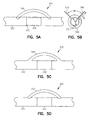
- Figures 5A-5D show a lead 500 constructed and arranged for fixation in the coronary sinus, where the lead 500 includes any of the above and below discussed leads.
- the silicone arches 540 in one option, are attached to and extend from a lead body 520 opposite the contact area 536 of electrode 532.
- the arches 540 provide spring forces to position the electrode 532 against the vessel wall, and help to reduce dislodgement and keep pacing thresholds lower.
- the arches 540 also reduce complications arising in the event that the lead 500 must be removed.
- the arch or arches 540 are part of a molded part of the lead 500.
- the arches 540 are straight silicone rubber cylinders affixed to the lead body 520 wall by glue in two locations that force the cylinders to assume an arched configuration.
- molded components in the shape of an arch are positioned on the lead body 520, as shown at Figure 5A and 5B .
- the arches 540 straddle the electrode 532, as shown in Figures 5A, 5C, and 5D .
- any of the above mentioned arches 540 provide a side thrust to the lead body 520 when that lead body 520 is advanced into a narrow vessel with an inner diameter less than the combined distance of the lead body outer diameter (d, as shown at Figure 5B ) and the maximum height (h, as shown at Figure 5B ) of the arch.
- the side thrust will force the electrode 532 against the vessel wall in a position opposite of the arches 540.
- These arches 540 are provided to reduce the rate of two types of complications. First, during implantation of a lead body 520 having arches 540, that lead body 520 could be manipulated back and forth in the vessel.
- the lead 500 also comprises a helical portion as shown at Figures 1-2 and 3A-3C .
- the lead body 520 may be made of a biocompatible material having shape memory characteristics such that it will return to its preformed shape once implanted and a stylet or guidewire is removed.
- An example of such a material is polyether polyurethane.
- the lead body may have portions which have shape memory characteristics, comprising either a shape memory polymer or a shape memory metal.
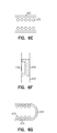
- Figures 6A-6G show a lead 600 adapted for implantation and fixation in the coronary sinus.
- Figure 6A shows the entire lead 600
- Figures 6B - 6G illustrate a portion of the lead 600.
- the lead body 620 is generally shaped with the same or smaller radius of curvature as the coronary sinus, so that it hugs the anatomy of the coronary sinus when the lead 600 is implanted.
- the shape of the lead body 620 hugging the myocardial wall of the coronary sinus urges the electrodes 632, 634 against the wall of the coronary sinus. Because of this geometry compatibility, the lead 600 will have good long term stability with relatively small forces on the lead body 620 and vessel walls. By distributing forces along the extent of the lead body 620, the possibility of lead or vessel wall damage is reduced.
- Figure 6B shows the distal portion of one example of lead 600 in greater detail.
- the lead body 620 is made of a biocompatible material having shape memory characteristics such that it will return to its preformed shape once implanted and a stylet or guidewire is removed.
- a biocompatible material having shape memory characteristics such that it will return to its preformed shape once implanted and a stylet or guidewire is removed.
- An example of such a material is polyether polyurethane.
- the lead body may have portions which have shape memory characteristics, comprising either a shape memory polymer or a shape memory metal.
- the lead body 620 is preformed such that is has a shape adapted to hug the heart while the lead 600 is disposed in the coronary sinus. It should be noted that the hugging shape of the lead body 620 can be combined with any of the above and below discussed examples.
- Figure 6C shows the side cross section of one example of the lead 600 along line C-C of Figure 6B .
- the lead 600 optionally has two sets of coils 672,673 at this portion.
- Figure 6D shows a pacing electrode 632 in greater detail.
- the electrode 632 optionally is partially masked with the contact portion 636 facing outward, so that in an implanted site, the electrode 632 contacts the vascular tissue adjacent the myocardial wall.
- Figure 6E shows the side cross section of the lead along line E-E of Figure 6B , of a lead portion having one set of coils 672.
- Figure 6F shows one example of electrode 634 in greater detail, showing a partially masked electrode 634 with the contact portion 638 facing inward.
- Figure 6G shows the side cross section of the lead 600 along line G-G of Figure 6B showing the end tip 690 of the lead 600.
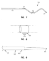
- Figure 7 illustrates another option for a cardiac vein lead, for example, a multiple polar lead 700 adapted for use in a cardiac vein.
- a third electrode 750 is added to a bipolar configuration, and the lead 700 can be used to pace and sense both the atrium and the ventricle. This configuration would allow the middle electrode 732 to be used as a common anode for both an atrial and ventricular bipole. This configuration would result in a lead utilizing the advantages of two bipole pairs with only three electrodes.
- the electrode 734 is electrically common with the electrode 750.
- the lead 700 has a proximal end (as shown at 102 of Figure 1 ), and attaches to a pulse sensor and generator (as shown at 140 of Figure 1 ).
- the lead body 720 is cylindrical in shape and includes one or more electrical conductors.
- the electrical conductors are made of a highly conductive, highly corrosion-resistant material.
- the one or more electrical conductors carry current and signals between the pulse sensor and generator and the electrodes 732, 734 and 750.
- the electrode 734 for example, a full ring electrode, serves as ground.
- the electrode 732 is a half ring electrode and serves as an atrial electrode.
- the electrode 750 is a PICOTIP (TM) electrode, and also comprises a ventricular electrode.
- FIG 8 shows a miniaturized high impedance PICOTIP (TM) electrode 850 constructed and arranged to be a side mounted electrode, which can be used with any of the leads discussed herein.
- This miniaturized electrode 850 increases electrode impedance by using a smaller exposed area.
- Electrode 850 comprises an electrode mesh 852 which increases chronic lead stability by providing local tissue ingrowth into the electrode mesh.
- the PICOTIP (TM) electrode protrudes from the lead body to enhance intimate wall contact.
- a lead according to the coronary vein leads described herein is implanted in any suitable manner, for example, as follows. Venous access is obtained via the subclavian, cephalic or jugular vein. A standard stylet is inserted into the lead to straighten it and provide stiffness for insertion of the lead into the vasculature. The coronary vein lead will then be guided into the coronary sinus/great cardiac vein. Once the coronary vein lead is positioned, the stylet will be removed. The preferred position for coronary vein lead placement is, in one option, to place the tip of the coronary vein lead near the origin of the great cardiac vein just proximal to the point where it originates from the interventricular vein. This will position the pacing electrodes near the end of the coronary sinus.
- the lead is tested for P-wave, P/R ratio and atrial and ventricular threshold.
- the lead will be manipulated and repositioned to maximize P-Wave and P/R ratios, and minimize atrial voltage threshold.
- Target thresholds will be below 2.0 volts with a P-wave above 2 mVolts and a P/R ratio above 2.
- An optional method for implanting these leads is to use an "over the wire” method. This involves (1) placing a guide catheter into the coronary sinus (2) threading a guide wire into the coronary veins, and (3) pushing the lead over the guide wire.
- a slender distal tubing or stylet/conductor coil section was instrumental in improving the ability of the medical personnel to position these leads. It is believed that this feature provided the distal portion of the lead with a guiding means that easily followed the vasculature. This was accomplished only when the diameter of this guiding section was considerably less than that of the vasculature.
- a lead body 920 having a tapered flexible distal tip 990 at its distal end 904 is shown which allows for easier access to distal veins.
- the outer diameter 980 of the lead body 920 tapers from the proximal portion 902 to the distal end 990 of the distal portion 904.
- the tapered lead body provides a smaller outer diameter at the distal end 990, and allows more easy access to the distal veins, which have a decreasing inner diameter, and can be more complex.
- a lead is shown generally at 1000.
- the lead 1000 provides ventricular pacing and sensing with or without atrial pacing and sensing.
- the lead 1000 provides atrial pacing and sensing with or without ventricular pacing and sensing.
- the lead 1000 provides ventricular pacing and sensing with or without sided defibrillation.
- the lead 1000 has a proximal end shown generally at 1002 and a distal end shown generally at 1004.
- the lead 1000 has a connector terminal 1010 at its proximal end and a lead body 1020, and is constructed and arranged for insertion into the coronary sinus.
- the lead 1000 attaches to a pulse sensor and generator 1040.
- the lead body 1020 has multiple electrodes.
- Proximal ring electrodes 1006 and 1008 are provided for atrial or ventricular sensing and distal electrodes 1012 and 1014 are provided for ventricular sensing and pacing.
- Connector terminal 1010 electrically connects the various electrodes and conductors within the lead body to the pulse sensor and generator 1040.
- the pulse sensor and generator 1040 also contains electronics to sense various pulses of the heart and also produce pulsing signals for delivery to the heart.
- the pulse sensor and generator 1040 also contains electronics and software necessary to detect certain types arrhythmias and to correct for them. Physicians are able to program the pulse sensor and generator to correct a particular arrhythmia that the patient may have. It should be noted that there are numerous types of connector terminals which connect to a pulse sensing and generating unit 1040.
- the distal end 1004 of the lead 1000 is placed far enough into the coronary venous system to stimulate the ventricle, as shown for example, in Figure 3B .
- This stimulation may occur at the base of the ventricle, the middle ventricle or the apex of the ventricle.
- the lead 1000 is instantiated only for pacing and sensing purposes, and the lead 1000 may have a unipolar or bipolar distal electrodes.
- the lead 1000 has multiple pairs of distal electrodes for multisite ventricular pacing. Electrodes 1046 and 1048 form an electrode pair located in the coronary sinus/great cardiac vein, and electrodes 1050 and 1052 form an electrode pair located in the ventricular portion of the lead 1000, implanted in the coronary venous system. Electrodes 1054 and 1056 also form an electrode pair located on the ventricular portion of the lead 1000 implanted in the coronary venous system.
- the example shown at Figure 10B may have a lead body 420 made of a biocompatible material having shape memory characteristics such that it will return to its preformed shape once implanted and a stylet or guidewire is removed.
- a biocompatible material having shape memory characteristics such that it will return to its preformed shape once implanted and a stylet or guidewire is removed.
- An example of such a material is polyether polyurethane.
- the lead body may have portions which have shape memory characteristics, comprising either a shape memory polymer or a shape memory metal.
- the lead 1000 has proximal electrodes, shown at 1006 and 1008 of Figure 10A , which are either bipolar or unipolar, for sensing and/or pacing of the atrium. In one example, multiple pairs or multiple sets of electrodes may be used for bi-atrial pacing.
- An optional distal electrode 1014 of the lead 1000 serves as a distal shocking electrode for the purpose of delivering a high energy shock greater than about 0.01 Joule to the ventricle. This distal shocking electrode may be added to any of the lead configurations disclosed herein.
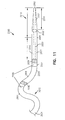
- a lead 2000 constructed in accordance with an embodiment is illustrated in Figure 11 . It should be noted that the lead 2000 and features thereof can be combined with the features discussed in the above described and illustrated examples.
- the lead 2000 comprises an open lumen lead, in one option.
- the lead 2000 is suitable for implantation within a body using a stylet, catheter, and/or guidewire.
- the lead 2000 has a lead body 2006 that extends to a distal end 2002, and has an atraumatic tip assembly 2010, as further described below.
- the lead 2000 includes a seal within the atraumatic tip assembly 2010.
- the seal in one option, comprises a hemostasis mechanism such as a polymer membrane.
- the lead 2000 includes a biased portion 2030 at an intermediate portion 2004 of the lead 2000, and a non-biased portion 2032 distal to the biased portion 2030.
- the biased portion 2030 extends from a first end 2033 to a second end 2034.
- the biased portion 2030 has a helical shape as discussed above (See e.g. Figures 3B and 3C ).
- the biased portion 2030 has a helical shape with 1 - 2 turns.
- one or more biases are formed within the biased portion 2030.
- the biased portion 2030 is formed into a bias with, for example, shape memory material such that the lead body 2006 is straightened during implantation, and biased once implanted, for example, once the stylet is removed from the lead body 2006.
- a suitable material although not limited to such material, is polyether polyurethane.
- shape memory material for the conductor can be used, such that the conductor can be formed with a bias.
- the biased portion 2030 assists in maintaining the lead 2000 within a passage, such as a vein or artery.
- the biased portion 2030 assists in enhancing tissue-electrode contact.
- the lead 2000 further includes electrodes 2036.
- the electrodes 2036 are disposed on the lead body 2006 along the biased portion 2030, where the biased portion 2030 would assist in fixation of the one or more electrodes 2036 and/or enhance tissue contact.
- the electrodes 2036 are disposed 120 degrees apart along the biased portion 2030, which increases the opportunity for the electrodes 2036 to make contact with the myocardial wall.
- a steroid collar 2038 is disposed directly adjacent to the one or more electrodes 2036, for example, along the biased portion 2030.
- the biased portion 2030 further enhances the effectiveness of the steroid collar 2038 by biasing a portion of the steroid collar 2038 toward the tissue.
- the lead 2000 further includes another electrode 2037 along the non-biased portion 2032, and optionally another steroid collar 2039 directly adjacent to the electrode 2037.
- the lead 2000 includes an atraumatic tip assembly 2010.
- the atraumatic tip assembly 2010 includes a flexible, tapered portion 2012 that is significantly more flexible than the biased portion 2030. This allows for improved maneuverability of the lead 2000 through tortuous vasculature, and allows for the lead 2000 to be implanted more easily and quickly than conventional leads. Furthermore, the flexible tapered portion 2012 allows for the guidewire, if used, to better guide the lead 2000 without interference from the biased portion 2030.
- the tapered portion 2012 begins, in one option, at the distal end 2002 of the lead body 2006 and extends to the intermediate portion 2004 of the lead 2000 and ends at 2005. Disposed between 2005 and the biased portion 2030 is a portion 2007 that extends, in one option, for a length of 5 - 10 cm, which further assists in the maneuverability of the lead 2000. In another option, the tapered portion 2012 begins at the distal end 2002 of the lead body 2006 and extends until the biased portion 2030 of the lead body 2006. The length 2014 of the tapered portion 2012, in another option, is 1 - 2 cm. The tapered portion 2012 assists in allowing for the lead body 2006 to more easily traverse vessels that are generally narrow, make tight turns, and frequently branch off.
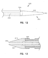
- the lead 2000 further includes at least one conductor 2020.
- the at least one conductor 2020 in one option, does not extend to the distal end 2002 of the lead body 2006. This allows for enhanced flexibility of the atraumatic tip assembly 2010, where the distal portion includes all, for example, rubber material without any rigidity from the conductors.
- the at least one conductor 2020 terminates at 2022 along a portion of the tapered portion 2012 of the lead body 2006.
- the at least one conductor 2020 terminates at 2024, that is proximal to the tapered portion 2012, as shown in Figure 12 . In this configuration, no conductor 2020 would be present along the tapered portion 2012, allowing for enhanced flexibility of the tapered portion 2012.
- the conductor 2020 comprises one or more coiled wires, having an inner diameter. The inner diameter, optionally, is isodiametric along the entire length of the conductor 2020, providing for further options with respect to flexibility for the atraumatic tip assembly 2010.
- the lead 2000 further includes, in one option, radiopaque materials within the lead body 2006, for example incorporated into the lead body 2006 at the distal end 2002 of the lead body 2006.
- a pre-molded tip assembly is formed of rubber, or other flexible material, filled with radiopaque material, where optionally the entire tapered portion is formed of the filled material 2007, as shown in Figure 13 .
- the lead body 2006 is formed of a flexible material, such as, but not limited to, LSR or Gumstock.
- radiopaque materials include, but are not limited to, barium sulfate, bismuth subcarbonate, tungston powder, platinum powder, platinum/iridium alloy powder, or a Pt Ir marker band. Varying the material selection of the lead body 2006 for the atraumatic tip assembly 2010 will allow for providing a more flexible atraumatic tip assembly 2010. In addition, having the radiopaque material at the distal end 2002 of the lead body 2006 will allow for a physician to more accurately determine the location of the lead 2000 within a passage of a body.
- the lead advantageously allows for effective use of a biased portion on a lead body in combination with an atraumatic tip assembly.
- the biased portion allows for gentle and effective forces against passage walls enabling the lead to be positionally maintained therein.
- the biased portion ensures the electrode is placed up against the passage wall with sufficient force.
- the spacing of the electrodes along the biased portion provides for an increased opportunity for the electrode to be placed against the passage wall.
- the atraumatic tip assembly is extremely flexible, relative to the biased portion, which allows for improved maneuverability of the lead through tortuous vasculature, and allows for the lead to be implanted more easily and quickly than conventional leads.
- the flexible tapered portion of the atraumatic tip assembly allows for the guidewire or stylet, if used, to better guide the lead without interference from the biased portion.
- the leads described herein provide several advantages over previous leads.
- the leads provide, in one option, the ability to sense and pace the heart using leads positioned within the cardiac vasculature, and further the leads provide the ability to pace and/or sense the left heart. It has been found that by placing a therapeutic lead near the atrium, but not in the atrium, higher amplitude electrograms may be detected as compared to a standard endocardial lead. Further, it has been found that left sided pacing may help suppress atrial arrhythmias, particularly those originating near the left atrium. Still further, it has been found that the ability to critically control the timing between pacing the atria and ventricles of the heart is of utility in optimizing pacing therapies.
- a lead is provided that is a right side lead and is placed within the coronary sinus, and is then advanced from the coronary sinus toward the left atrium to provide left sided sensing and pacing.
Claims (12)
- Leitung, umfassendeinen Leitungskörper (120, 220, 620, 2006), aufweisend einen proximalen Teil, einen distalen Teil und einen mittleren Teil zwischen dem proximalen Teil und dem distalen Teil, wobei der Leitungskörper ein sich durch den Leitungskörper erstreckendes isodiametrisches Lumen aufweist;mehrere mit dem Leitungskörper gekoppelte Elektroden (122, 132, 134; 232, 234, 242, 244, 252, 254; 432, 434, 454; 532; 632, 634; 2036, 2037), wobei der Leitungskörper dazu angepasst ist, Signale an die und von der mindestens einen Elektrode zu übertragen;einen Verbinder (110), der an dem proximalen Ende der Leitung angeordnet ist; undwobei der mittlere Teil (104; 230; 2030) des Leitungskörpers einen vorgeformten vorgespannten Teil (104; 230; 2030), umfassend einen spiralförmigen Teil (130), beinhaltet, daran aufweisend die zwei oder mehr Elektroden, wobei der spiralförmige Teil aufgebaut und angeordnet ist, die zwei oder mehr Elektroden in Richtung einer Wand eines Durchgangs zu drängen, undwobei der Leitungskörper ferner einen nicht vorgespannten Teil beinhaltet, der zwischen dem vorgeformten vorgespannten Teil und dem distalen Ende des Leitungskörpers angeordnet ist, wobei der nicht vorgespannte Teil mindestens eine Elektrode (252; 254; 2037) und einen flexiblen Teil am distalen Ende des Leitungskörpers, der flexibler ist als der vorgepannte Teil, beinhaltet,
dadurch gekennzeichnet, dass sich das isodiametrische Lumen zu einem offenen distalen Ende des Leitungskörpers erstreckt und dass sich der flexible Teil am distalen Ende des Leitungskörpers verjüngt. - Leitung nach Anspruch 1, wobei der spiralförmige Teil (130) mehr als zwei Elektroden beinhaltet.
- Leitung nach Anspruch 1, wobei die mehreren Elektroden eine erste Elektrode (132; 232; 432; 632; 2036) die zugehörig zum distalen Teil des Leitungskörpers ist, beinhalten, wobei die erste Elektrode einen ersten Elektrodenkontaktbereich beinhaltet, und eine zweite Elektrode (134; 234; 434; 634; 2037), die zugehörig zum distalen Teil des Leitungskörpers ist, beinhaltet, wobei die zweite Elektrode einen zweiten Elektrodenkontaktbereich beinhaltet, wobei der distale Teil der Leitung aufgebaut und angeordnet ist, die erste und zweite Elektrode in Richtung einer Wand eines Durchgangs zu drängen.
- Leitung nach Anspruch 3, wobei die erste Elektrode und die zweite Elektrode in unmittelbarer Nähe zueinander beabstandet sind, wobei die erste Elektrode und die zweite Elektrode ca. 1-5mm voneinander beabstandet sind.
- Leitung nach Anspruch 1 oder 4, wobei die erste Elektrode und/oder die zweite Elektrode (132, 134) teilweise umhüllt sind und ferner einen elektrischen Kontaktteil (136, 138) umfassen, der aufgebaut und angeordnet ist, eine Wand eines Durchgangs zu berühren.
- Leitung nach einem der Ansprüche 1-5, wobei der Leitungskörper ferner eine außenseitige Steroidmanschette (256, 2038), die in unmittelbarer Nähe zu einer Elektrode angeordnet ist, umfasst.
- Leitung nach Anspruch 2, wobei die mehr als zwei Elektroden um 120 Grad voneinander entlang des spiralförmigen Teils beabstandet sind.
- Leitung nach Anspruch 1, wobei zumindest ein Teil des Leitungskörpers einen Formgedächtniswerkstoff umfasst.
- Leitung nach Anspruch 8, wobei der Leitungskörper (120, 220, 620, 2006) aus einem biokompatiblen Werkstoff hergestellt ist, der Formgedächtniseigenschaften aufweist derart, dass er in seine vorgeformte Form zurückkehrt, sobald er implantiert ist und ein Mandrin oder Führungsdraht entfernt wurde.
- Leitung nach Anspruch 1, wobei der Durchmesser des spiralförmigen Teils im Bereich von 0,25 cm bis 2 cm liegt.
- Leitung nach Anspruch 11, wonach die Steigung der Spirale im Bereich von 0,5 cm bis 2,5 cm liegt.
- Leitung nach einem der vorhergehenden Ansprüche, wobei der spiralförmige Teil eine zylindrische Spiralform aufweist.
Applications Claiming Priority (2)
| Application Number | Priority Date | Filing Date | Title |
|---|---|---|---|
| US09/651,340 US6584362B1 (en) | 2000-08-30 | 2000-08-30 | Leads for pacing and/or sensing the heart from within the coronary veins |
| EP01968281A EP1363697B1 (de) | 2000-08-30 | 2001-08-30 | In koronarvenen implantierbare leitung zur herzstimulation oder zum detektieren von herzereignissen |
Related Parent Applications (2)
| Application Number | Title | Priority Date | Filing Date |
|---|---|---|---|
| EP01968281.4 Division | 2001-08-30 | ||
| EP01968281A Division EP1363697B1 (de) | 2000-08-30 | 2001-08-30 | In koronarvenen implantierbare leitung zur herzstimulation oder zum detektieren von herzereignissen |
Publications (3)
| Publication Number | Publication Date |
|---|---|
| EP2092955A2 EP2092955A2 (de) | 2009-08-26 |
| EP2092955A3 EP2092955A3 (de) | 2010-04-14 |
| EP2092955B1 true EP2092955B1 (de) | 2016-09-21 |
Family
ID=24612512
Family Applications (2)
| Application Number | Title | Priority Date | Filing Date |
|---|---|---|---|
| EP01968281A Expired - Lifetime EP1363697B1 (de) | 2000-08-30 | 2001-08-30 | In koronarvenen implantierbare leitung zur herzstimulation oder zum detektieren von herzereignissen |
| EP09161205.1A Expired - Lifetime EP2092955B1 (de) | 2000-08-30 | 2001-08-30 | Leitungen zur Schrittstimulierung und/oder Überwachung des Herzens von den Koronarvenen aus |
Family Applications Before (1)
| Application Number | Title | Priority Date | Filing Date |
|---|---|---|---|
| EP01968281A Expired - Lifetime EP1363697B1 (de) | 2000-08-30 | 2001-08-30 | In koronarvenen implantierbare leitung zur herzstimulation oder zum detektieren von herzereignissen |
Country Status (6)
| Country | Link |
|---|---|
| US (6) | US6584362B1 (de) |
| EP (2) | EP1363697B1 (de) |
| AT (1) | ATE507869T1 (de) |
| AU (1) | AU2001288538A1 (de) |
| DE (1) | DE60144577D1 (de) |
| WO (1) | WO2002018006A2 (de) |
Families Citing this family (240)
| Publication number | Priority date | Publication date | Assignee | Title |
|---|---|---|---|---|
| US8728065B2 (en) * | 2009-07-02 | 2014-05-20 | St. Jude Medical, Atrial Fibrillation Division, Inc. | Apparatus and methods for contactless electrophysiology studies |
| US6463334B1 (en) | 1998-11-02 | 2002-10-08 | Cardiac Pacemakers, Inc. | Extendable and retractable lead |
| KR100312753B1 (ko) * | 1998-10-13 | 2002-04-06 | 윤종용 | 광시야각액정표시장치 |
| US6493586B1 (en) * | 2000-08-30 | 2002-12-10 | Cardiac Pacemakers, Inc. | Site reversion in cardiac rhythm management |
| US6584362B1 (en) * | 2000-08-30 | 2003-06-24 | Cardiac Pacemakers, Inc. | Leads for pacing and/or sensing the heart from within the coronary veins |
| US7499742B2 (en) | 2001-09-26 | 2009-03-03 | Cvrx, Inc. | Electrode structures and methods for their use in cardiovascular reflex control |
| US7840271B2 (en) * | 2000-09-27 | 2010-11-23 | Cvrx, Inc. | Stimulus regimens for cardiovascular reflex control |
| US7623926B2 (en) | 2000-09-27 | 2009-11-24 | Cvrx, Inc. | Stimulus regimens for cardiovascular reflex control |
| US8086314B1 (en) | 2000-09-27 | 2011-12-27 | Cvrx, Inc. | Devices and methods for cardiovascular reflex control |
| US7616997B2 (en) | 2000-09-27 | 2009-11-10 | Kieval Robert S | Devices and methods for cardiovascular reflex control via coupled electrodes |
| US7130682B2 (en) | 2000-12-26 | 2006-10-31 | Cardiac Pacemakers, Inc. | Pacing and sensing vectors |
| US6480740B2 (en) | 2000-12-26 | 2002-11-12 | Cardiac Pacemakers, Inc. | Safety pacing in multi-site CRM devices |
| US6936040B2 (en) * | 2001-10-29 | 2005-08-30 | Medtronic, Inc. | Method and apparatus for endovenous pacing lead |
| US20030105501A1 (en) * | 2001-12-03 | 2003-06-05 | Warman Eduardo N. | Shaped lead with electrodes |
| US20030199961A1 (en) | 2002-04-03 | 2003-10-23 | Bjorklund Vicki L. | Method and apparatus for fixating a pacing lead of an implantable medical device |
| US7653438B2 (en) * | 2002-04-08 | 2010-01-26 | Ardian, Inc. | Methods and apparatus for renal neuromodulation |
| US7110815B2 (en) * | 2002-05-06 | 2006-09-19 | Cardiac Pacemakers, Inc. | System and method for providing temporary stimulation therapy to optimize chronic electrical performance for electrodes used in conjunction with a cardiac rhythm management system |
| AU2003296956A1 (en) * | 2002-12-11 | 2004-06-30 | Proteus Biomedical, Inc. | Monitoring and treating hemodynamic parameters |
| WO2005000398A2 (en) | 2003-06-04 | 2005-01-06 | Synecor | Intravascular electrophysiological system and methods |
| US7082336B2 (en) * | 2003-06-04 | 2006-07-25 | Synecor, Llc | Implantable intravascular device for defibrillation and/or pacing |
| US7617007B2 (en) | 2003-06-04 | 2009-11-10 | Synecor Llc | Method and apparatus for retaining medical implants within body vessels |
| US8239045B2 (en) | 2003-06-04 | 2012-08-07 | Synecor Llc | Device and method for retaining a medical device within a vessel |
| US20050055058A1 (en) | 2003-09-08 | 2005-03-10 | Mower Morton M. | Method and apparatus for intrachamber resynchronization |
| US20050080472A1 (en) * | 2003-10-10 | 2005-04-14 | Atkinson Robert Emmett | Lead stabilization devices and methods |
| US7657312B2 (en) | 2003-11-03 | 2010-02-02 | Cardiac Pacemakers, Inc. | Multi-site ventricular pacing therapy with parasympathetic stimulation |
| WO2005058415A2 (en) | 2003-12-12 | 2005-06-30 | Synecor, Llc | Implantable medical device having pre-implant exoskeleton |
| US7245973B2 (en) * | 2003-12-23 | 2007-07-17 | Cardiac Pacemakers, Inc. | His bundle mapping, pacing, and injection lead |
| US8024050B2 (en) | 2003-12-24 | 2011-09-20 | Cardiac Pacemakers, Inc. | Lead for stimulating the baroreceptors in the pulmonary artery |
| US7668594B2 (en) * | 2005-08-19 | 2010-02-23 | Cardiac Pacemakers, Inc. | Method and apparatus for delivering chronic and post-ischemia cardiac therapies |
| US7509166B2 (en) | 2003-12-24 | 2009-03-24 | Cardiac Pacemakers, Inc. | Automatic baroreflex modulation responsive to adverse event |
| US7460906B2 (en) | 2003-12-24 | 2008-12-02 | Cardiac Pacemakers, Inc. | Baroreflex stimulation to treat acute myocardial infarction |
| US7643875B2 (en) * | 2003-12-24 | 2010-01-05 | Cardiac Pacemakers, Inc. | Baroreflex stimulation system to reduce hypertension |
| US8126560B2 (en) * | 2003-12-24 | 2012-02-28 | Cardiac Pacemakers, Inc. | Stimulation lead for stimulating the baroreceptors in the pulmonary artery |
| US8200331B2 (en) * | 2004-11-04 | 2012-06-12 | Cardiac Pacemakers, Inc. | System and method for filtering neural stimulation |
| EP1595571B1 (de) * | 2004-05-14 | 2008-02-13 | BIOTRONIK CRM Patent AG | Elektrodenleitung |
| US7225035B2 (en) * | 2004-06-24 | 2007-05-29 | Medtronic, Inc. | Multipolar medical electrical lead |
| US20060020314A1 (en) * | 2004-07-23 | 2006-01-26 | Cardiac Pacemakers, Inc. | Systems and methods for characterizing leads |
| DE102004036397A1 (de) * | 2004-07-23 | 2006-02-09 | Biotronik Vi Patent Ag | Stimulationselektrodenleitung |
| US7395120B2 (en) * | 2004-08-13 | 2008-07-01 | The General Hospital Corporation | Telescoping, dual-site pacing lead |
| US20060036306A1 (en) * | 2004-08-13 | 2006-02-16 | Heist E K | Telescoping, dual-site pacing lead |
| US7515970B2 (en) | 2004-08-18 | 2009-04-07 | Cardiac Pacemakers, Inc. | Transeptal lead |
| US20060041297A1 (en) * | 2004-08-23 | 2006-02-23 | Medtronic, Inc. | Novel electrode assembly for medical electrical leads |
| US8219212B2 (en) * | 2004-08-23 | 2012-07-10 | Medtronic, Inc. | Distal portions for medical electrical leads |
| WO2006069322A2 (en) * | 2004-12-22 | 2006-06-29 | Proteus Biomedical, Inc. | Implantable addressable segmented electrodes |
| US7647109B2 (en) * | 2004-10-20 | 2010-01-12 | Boston Scientific Scimed, Inc. | Leadless cardiac stimulation systems |
| WO2006045075A1 (en) | 2004-10-20 | 2006-04-27 | Boston Scientific Limited | Leadless cardiac stimulation systems |
| US7532933B2 (en) | 2004-10-20 | 2009-05-12 | Boston Scientific Scimed, Inc. | Leadless cardiac stimulation systems |
| US20060089694A1 (en) * | 2004-10-21 | 2006-04-27 | Cardiac Pacemakers, Inc. | Delivery system and method for pulmonary artery leads |
| US7664550B2 (en) * | 2004-11-30 | 2010-02-16 | Medtronic, Inc. | Method and apparatus for detecting left ventricular lead displacement based upon EGM change |
| US7328063B2 (en) | 2004-11-30 | 2008-02-05 | Cardiac Pacemakers, Inc. | Method and apparatus for arrhythmia classification using atrial signal mapping |
| US7433739B1 (en) * | 2004-11-30 | 2008-10-07 | Pacesetter, Inc. | Passive fixation mechanism for epicardial sensing and stimulation lead placed through pericardial access |
| US8014861B2 (en) | 2004-12-20 | 2011-09-06 | Cardiac Pacemakers, Inc. | Systems, devices and methods relating to endocardial pacing for resynchronization |
| US8423139B2 (en) | 2004-12-20 | 2013-04-16 | Cardiac Pacemakers, Inc. | Methods, devices and systems for cardiac rhythm management using an electrode arrangement |
| US8050756B2 (en) | 2004-12-20 | 2011-11-01 | Cardiac Pacemakers, Inc. | Circuit-based devices and methods for pulse control of endocardial pacing in cardiac rhythm management |
| US8326423B2 (en) | 2004-12-20 | 2012-12-04 | Cardiac Pacemakers, Inc. | Devices and methods for steering electrical stimulation in cardiac rhythm management |
| AR047851A1 (es) | 2004-12-20 | 2006-03-01 | Giniger Alberto German | Un nuevo marcapasos que restablece o preserva la conduccion electrica fisiologica del corazon y un metodo de aplicacion |
| US8290586B2 (en) * | 2004-12-20 | 2012-10-16 | Cardiac Pacemakers, Inc. | Methods, devices and systems for single-chamber pacing using a dual-chamber pacing device |
| US8010192B2 (en) | 2004-12-20 | 2011-08-30 | Cardiac Pacemakers, Inc. | Endocardial pacing relating to conduction abnormalities |
| US8010191B2 (en) | 2004-12-20 | 2011-08-30 | Cardiac Pacemakers, Inc. | Systems, devices and methods for monitoring efficiency of pacing |
| US8005544B2 (en) | 2004-12-20 | 2011-08-23 | Cardiac Pacemakers, Inc. | Endocardial pacing devices and methods useful for resynchronization and defibrillation |
| US20080077186A1 (en) * | 2006-04-18 | 2008-03-27 | Proteus Biomedical, Inc. | High phrenic, low capture threshold pacing devices and methods |
| US7295874B2 (en) * | 2005-01-06 | 2007-11-13 | Cardiac Pacemakers, Inc. | Intermittent stress augmentation pacing for cardioprotective effect |
| US7587238B2 (en) | 2005-03-11 | 2009-09-08 | Cardiac Pacemakers, Inc. | Combined neural stimulation and cardiac resynchronization therapy |
| US7840266B2 (en) * | 2005-03-11 | 2010-11-23 | Cardiac Pacemakers, Inc. | Integrated lead for applying cardiac resynchronization therapy and neural stimulation therapy |
| WO2006098996A1 (en) | 2005-03-11 | 2006-09-21 | Cardiac Pacemakers, Inc. | Combined neural stimulation and cardiac resynchronization therapy |
| JP5027797B2 (ja) | 2005-03-31 | 2012-09-19 | プロテウス バイオメディカル インコーポレイテッド | 心臓再同期化のための多重電極ペーシングの自動最適化 |
| US7499748B2 (en) * | 2005-04-11 | 2009-03-03 | Cardiac Pacemakers, Inc. | Transvascular neural stimulation device |
| US20060235499A1 (en) * | 2005-04-14 | 2006-10-19 | Cardiac Pacemakers, Inc. | Coated lead fixation electrode |
| US7962208B2 (en) * | 2005-04-25 | 2011-06-14 | Cardiac Pacemakers, Inc. | Method and apparatus for pacing during revascularization |
| US20060253181A1 (en) * | 2005-05-05 | 2006-11-09 | Alfred E. Mann Foundation For Scientific Research | Lead insertion tool |
| US7734348B2 (en) * | 2005-05-10 | 2010-06-08 | Cardiac Pacemakers, Inc. | System with left/right pulmonary artery electrodes |
| US7765000B2 (en) * | 2005-05-10 | 2010-07-27 | Cardiac Pacemakers, Inc. | Neural stimulation system with pulmonary artery lead |
| US20060259088A1 (en) * | 2005-05-13 | 2006-11-16 | Pastore Joseph M | Method and apparatus for delivering pacing pulses using a coronary stent |
| US7917210B2 (en) * | 2005-05-13 | 2011-03-29 | Cardiac Pacemakers, Inc. | Method and apparatus for cardiac protection pacing |
| US7894896B2 (en) * | 2005-05-13 | 2011-02-22 | Cardiac Pacemakers, Inc. | Method and apparatus for initiating and delivering cardiac protection pacing |
| US7617003B2 (en) * | 2005-05-16 | 2009-11-10 | Cardiac Pacemakers, Inc. | System for selective activation of a nerve trunk using a transvascular reshaping lead |
| US20060276868A1 (en) * | 2005-06-03 | 2006-12-07 | Seth Worley | Coronary sinus lead for pacing the left atrium |
| US20060276869A1 (en) * | 2005-06-03 | 2006-12-07 | Seth Worley | Coronary sinus lead for pacing the left atrium |
| US8862243B2 (en) | 2005-07-25 | 2014-10-14 | Rainbow Medical Ltd. | Electrical stimulation of blood vessels |
| WO2007021804A2 (en) | 2005-08-12 | 2007-02-22 | Proteus Biomedical, Inc. | Evaluation of depolarization wave conduction velocity |
| US7515971B1 (en) * | 2005-09-09 | 2009-04-07 | Pacesetter, Inc. | Left atrial pressure sensor lead |
| US8731659B2 (en) | 2005-09-20 | 2014-05-20 | Cardiac Pacemakers, Inc. | Multi-site lead/system using a multi-pole connection and methods therefor |
| US20070112402A1 (en) * | 2005-10-19 | 2007-05-17 | Duke University | Electrode systems and related methods for providing therapeutic differential tissue stimulation |
| US7616990B2 (en) | 2005-10-24 | 2009-11-10 | Cardiac Pacemakers, Inc. | Implantable and rechargeable neural stimulator |
| US10406366B2 (en) * | 2006-11-17 | 2019-09-10 | Respicardia, Inc. | Transvenous phrenic nerve stimulation system |
| CA2630211C (en) | 2005-11-18 | 2016-11-01 | Cardiac Concepts, Inc. | System and method to modulate phrenic nerve to prevent sleep apnea |
| US8204586B2 (en) * | 2005-11-22 | 2012-06-19 | Proteus Biomedical, Inc. | External continuous field tomography |
| US8108034B2 (en) | 2005-11-28 | 2012-01-31 | Cardiac Pacemakers, Inc. | Systems and methods for valvular regurgitation detection |
| EP1957147B1 (de) | 2005-12-09 | 2010-12-29 | Boston Scientific Scimed, Inc. | Herzstimulationssystem |
| US7546165B2 (en) * | 2005-12-19 | 2009-06-09 | Cardiac Pacemakers, Inc. | Interconnections of implantable lead conductors and electrodes and reinforcement therefor |
| US8050774B2 (en) | 2005-12-22 | 2011-11-01 | Boston Scientific Scimed, Inc. | Electrode apparatus, systems and methods |
| US7885710B2 (en) * | 2005-12-23 | 2011-02-08 | Cardiac Pacemakers, Inc. | Method and apparatus for tissue protection against ischemia using remote conditioning |
| US20070156215A1 (en) * | 2005-12-29 | 2007-07-05 | Marc Jensen | Dilating lead tip |
| US7747334B2 (en) | 2006-03-23 | 2010-06-29 | Cardiac Pacemakers, Inc. | Left ventricular lead shapes |
| US7937161B2 (en) * | 2006-03-31 | 2011-05-03 | Boston Scientific Scimed, Inc. | Cardiac stimulation electrodes, delivery devices, and implantation configurations |
| US8457763B2 (en) * | 2006-04-27 | 2013-06-04 | Medtronic, Inc. | Implantable medical electrical stimulation lead fixation method and apparatus |
| US8126538B2 (en) | 2006-06-06 | 2012-02-28 | Cardiac Pacemakers, Inc. | Method and apparatus for introducing endolymphatic instrumentation |
| US7734341B2 (en) * | 2006-06-06 | 2010-06-08 | Cardiac Pacemakers, Inc. | Method and apparatus for gastrointestinal stimulation via the lymphatic system |
| US7526337B2 (en) * | 2006-06-06 | 2009-04-28 | Cardiac Pacemakers, Inc. | Method and device for lymphatic system monitoring |
| US20070282376A1 (en) | 2006-06-06 | 2007-12-06 | Shuros Allan C | Method and apparatus for neural stimulation via the lymphatic system |
| WO2007146060A2 (en) * | 2006-06-07 | 2007-12-21 | Cherik Bulkes | Self-anchoring electrical lead with multiple electrodes |
| WO2007146076A2 (en) * | 2006-06-07 | 2007-12-21 | Cherik Bulkes | Biological tissue stimulator with flexible electrode carrier |
| US7865248B2 (en) * | 2006-06-15 | 2011-01-04 | Cardiac Pacemakers, Inc. | Biasing and fixation features on leads |
| US7725197B2 (en) * | 2006-06-15 | 2010-05-25 | Cardiac Pacemakers, Inc. | Medical electrical lead with friction-enhancing fixation features |
| US20070293923A1 (en) * | 2006-06-15 | 2007-12-20 | Cardiac Pacemakers, Inc. | Lead with orientation feature |
| US20080097566A1 (en) * | 2006-07-13 | 2008-04-24 | Olivier Colliou | Focused segmented electrode |
| US8290600B2 (en) * | 2006-07-21 | 2012-10-16 | Boston Scientific Scimed, Inc. | Electrical stimulation of body tissue using interconnected electrode assemblies |
| US7840281B2 (en) | 2006-07-21 | 2010-11-23 | Boston Scientific Scimed, Inc. | Delivery of cardiac stimulation devices |
| US20080046059A1 (en) * | 2006-08-04 | 2008-02-21 | Zarembo Paul E | Lead including a heat fused or formed lead body |
| US20080039916A1 (en) * | 2006-08-08 | 2008-02-14 | Olivier Colliou | Distally distributed multi-electrode lead |
| US7917229B2 (en) | 2006-08-31 | 2011-03-29 | Cardiac Pacemakers, Inc. | Lead assembly including a polymer interconnect and methods related thereto |
| US8905999B2 (en) * | 2006-09-01 | 2014-12-09 | Cardiac Pacemakers, Inc. | Method and apparatus for endolymphatic drug delivery |
| WO2008034005A2 (en) | 2006-09-13 | 2008-03-20 | Boston Scientific Scimed, Inc. | Cardiac stimulation using leadless electrode assemblies |
| US20080114230A1 (en) * | 2006-11-14 | 2008-05-15 | Bruce Addis | Electrode support |
| US20080147168A1 (en) * | 2006-12-04 | 2008-06-19 | Terrance Ransbury | Intravascular implantable device having detachable tether arrangement |
| US8311633B2 (en) * | 2006-12-04 | 2012-11-13 | Synecor Llc | Intravascular implantable device having superior anchoring arrangement |
| US7662132B2 (en) * | 2007-01-25 | 2010-02-16 | Cardiac Pacemakers, Inc. | Expandable member for venous lead fixation |
| CA2877177C (en) | 2007-01-29 | 2018-05-22 | Simon Fraser University | Transvascular nerve stimulation apparatus and methods |
| US7949409B2 (en) * | 2007-01-30 | 2011-05-24 | Cardiac Pacemakers, Inc. | Dual spiral lead configurations |
| US8244378B2 (en) * | 2007-01-30 | 2012-08-14 | Cardiac Pacemakers, Inc. | Spiral configurations for intravascular lead stability |
| US20080183265A1 (en) * | 2007-01-30 | 2008-07-31 | Cardiac Pacemakers, Inc. | Transvascular lead with proximal force relief |
| US20080183187A1 (en) * | 2007-01-30 | 2008-07-31 | Cardiac Pacemakers, Inc. | Direct delivery system for transvascular lead |
| US20080183255A1 (en) * | 2007-01-30 | 2008-07-31 | Cardiac Pacemakers, Inc. | Side port lead delivery system |
| US20080183186A1 (en) * | 2007-01-30 | 2008-07-31 | Cardiac Pacemakers, Inc. | Method and apparatus for delivering a transvascular lead |
| US20080183264A1 (en) * | 2007-01-30 | 2008-07-31 | Cardiac Pacemakers, Inc. | Electrode configurations for transvascular nerve stimulation |
| US7917230B2 (en) * | 2007-01-30 | 2011-03-29 | Cardiac Pacemakers, Inc. | Neurostimulating lead having a stent-like anchor |
| US7937147B2 (en) * | 2007-02-28 | 2011-05-03 | Cardiac Pacemakers, Inc. | High frequency stimulation for treatment of atrial fibrillation |
| US8615296B2 (en) * | 2007-03-06 | 2013-12-24 | Cardiac Pacemakers, Inc. | Method and apparatus for closed-loop intermittent cardiac stress augmentation pacing |
| WO2008134651A2 (en) * | 2007-04-27 | 2008-11-06 | St. Jude Medical, Atrial Fibrillation Division, Inc. | Apparatus and method for positioning and retention of catheter |
| US8103359B2 (en) | 2007-05-17 | 2012-01-24 | Cardiac Pacemakers, Inc. | Systems and methods for fixating transvenously implanted medical devices |
| US20090024197A1 (en) * | 2007-07-18 | 2009-01-22 | Cardiac Pacemakers, Inc. | Elution control via geometric features of an implantable substance matrix |
| US20090088827A1 (en) * | 2007-10-02 | 2009-04-02 | Cardiac Pacemakers, Inc | Lead assembly providing sensing or stimulation of spaced-apart myocardial contact areas |
| WO2009075750A2 (en) | 2007-12-12 | 2009-06-18 | Cardiac Pacemakers, Inc. | System for delivering neurostimulation from pulmonary artery |
| WO2009097118A1 (en) * | 2008-01-29 | 2009-08-06 | Cardiac Pacemakers, Inc | Configurable intermittent pacing therapy |
| US8538535B2 (en) | 2010-08-05 | 2013-09-17 | Rainbow Medical Ltd. | Enhancing perfusion by contraction |
| US8738147B2 (en) | 2008-02-07 | 2014-05-27 | Cardiac Pacemakers, Inc. | Wireless tissue electrostimulation |
| WO2009131749A2 (en) | 2008-02-28 | 2009-10-29 | Proteus Biomedical, Inc. | Integrated circuit implementation and fault control system, device, and method |
| US8140155B2 (en) * | 2008-03-11 | 2012-03-20 | Cardiac Pacemakers, Inc. | Intermittent pacing therapy delivery statistics |
| US8483826B2 (en) * | 2008-03-17 | 2013-07-09 | Cardiac Pacemakers, Inc. | Deactivation of intermittent pacing therapy |
| US20090287266A1 (en) * | 2008-05-13 | 2009-11-19 | Mark Zdeblick | High-voltage tolerant multiplex multi-electrode stimulation systems and methods for using the same |
| US20100331941A1 (en) * | 2008-05-28 | 2010-12-30 | Walsh Robert G | Implantable fine wire lead for electrostimulation and sensing |
| US9242100B2 (en) | 2012-08-07 | 2016-01-26 | Nuax, Inc. | Optical fiber-fine wire lead for electrostimulation and sensing |
| US9513443B2 (en) * | 2008-05-28 | 2016-12-06 | John Lawrence Erb | Optical fiber-fine wire conductor and connectors |
| US9193313B2 (en) | 2012-03-22 | 2015-11-24 | Nuax, Inc. | Methods and apparatuses involving flexible cable/guidewire/interconnects |
| US9025598B1 (en) | 2012-03-22 | 2015-05-05 | Nuax, Inc. | Cable/guidewire/interconnects communication apparatus and methods |
| US8692117B2 (en) | 2008-05-28 | 2014-04-08 | Cardia Access, Inc. | Durable fine wire electrical conductor suitable for extreme environment applications |
| US20090318984A1 (en) * | 2008-06-19 | 2009-12-24 | Mokelke Eric A | External pacemaker with automatic cardioprotective pacing protocol |
| US9409012B2 (en) * | 2008-06-19 | 2016-08-09 | Cardiac Pacemakers, Inc. | Pacemaker integrated with vascular intervention catheter |
| US9037235B2 (en) | 2008-06-19 | 2015-05-19 | Cardiac Pacemakers, Inc. | Pacing catheter with expandable distal end |
| US20090318994A1 (en) * | 2008-06-19 | 2009-12-24 | Tracee Eidenschink | Transvascular balloon catheter with pacing electrodes on shaft |
| US8639357B2 (en) * | 2008-06-19 | 2014-01-28 | Cardiac Pacemakers, Inc. | Pacing catheter with stent electrode |
| US8244352B2 (en) | 2008-06-19 | 2012-08-14 | Cardiac Pacemakers, Inc. | Pacing catheter releasing conductive liquid |
| US20090318749A1 (en) * | 2008-06-19 | 2009-12-24 | Craig Stolen | Method and apparatus for pacing and intermittent ischemia |
| US8457738B2 (en) * | 2008-06-19 | 2013-06-04 | Cardiac Pacemakers, Inc. | Pacing catheter for access to multiple vessels |
| US8126571B2 (en) * | 2008-06-23 | 2012-02-28 | Cardiac Pacemakers, Inc. | Expandable assembly for cardiac lead fixation |
| WO2010002456A1 (en) * | 2008-07-01 | 2010-01-07 | Cardiac Pacemakers, Inc. | Pacing system controller integrated into indeflator |
| US8219209B2 (en) | 2008-08-15 | 2012-07-10 | Cardiac Pacemakers, Inc. | Implantable medical lead having reduced dimension tubing transition |
| CA2771158A1 (en) * | 2008-08-28 | 2010-03-04 | Thoratec Corporation | Implantable heart assist system |
| US20100056858A1 (en) * | 2008-09-02 | 2010-03-04 | Mokelke Eric A | Pacing system for use during cardiac catheterization or surgery |
| US8655458B2 (en) * | 2008-09-05 | 2014-02-18 | Cardiac Pacemakers, Inc. | Conformal electrodes for shaped medical device lead body segments |
| WO2010071849A2 (en) | 2008-12-19 | 2010-06-24 | Action Medical, Inc. | Devices, methods, and systems including cardiac pacing |
| US20100228331A1 (en) * | 2009-03-09 | 2010-09-09 | Pacesetter, Inc. | Implantable medical lead having a body with helical cable conductor construction and method of making same |
| US8412347B2 (en) * | 2009-04-29 | 2013-04-02 | Proteus Digital Health, Inc. | Methods and apparatus for leads for implantable devices |
| US8983600B2 (en) | 2009-05-15 | 2015-03-17 | Cardiac Pacemakers, Inc. | Method and apparatus for safety control during cardiac pacing mode transition |
| US8958873B2 (en) | 2009-05-28 | 2015-02-17 | Cardiac Pacemakers, Inc. | Method and apparatus for safe and efficient delivery of cardiac stress augmentation pacing |
| US20110004288A1 (en) * | 2009-06-12 | 2011-01-06 | Terrance Ransbury | Intravascular implantable device having integrated anchor mechanism |
| WO2010144916A2 (en) * | 2009-06-12 | 2010-12-16 | Innerpulse, Inc. | Methods and systems for anti-thrombotic intravascular implantable devices |
| WO2011011736A2 (en) | 2009-07-23 | 2011-01-27 | Proteus Biomedical, Inc. | Solid-state thin film capacitor |
| US8812104B2 (en) | 2009-09-23 | 2014-08-19 | Cardiac Pacemakers, Inc. | Method and apparatus for automated control of pacing post-conditioning |
| ES2550034T3 (es) * | 2009-09-23 | 2015-11-04 | Lake Region Manufacturing, Inc. D/B/A/ Lake Regional Medical | Cable conductor de electroestimulación de tipo alambre guía |
| US9468755B2 (en) * | 2009-09-30 | 2016-10-18 | Respicardia, Inc. | Medical lead with preformed bias |
| WO2011053369A1 (en) * | 2009-10-30 | 2011-05-05 | Cardiac Pacemakers, Inc. | Pacemaker with vagal surge monitoring and response |
| US8463398B2 (en) * | 2009-12-30 | 2013-06-11 | Cardiac Pacemakers, Inc. | Electrode surface modification for imparting current density directionality in lead electrodes |
| US9814874B2 (en) * | 2009-12-30 | 2017-11-14 | Cardiac Pacemakers, Inc. | Implantable lead electrode with asymmetrically distributed current density and methods for imparting current density directionality in lead electrodes |
| US8728562B2 (en) * | 2009-12-30 | 2014-05-20 | Cardiac Pacemakers, Inc. | Implantable leads with a unitary silicone component |
| AU2011213068A1 (en) * | 2010-02-02 | 2012-08-16 | Thoratec Llc | Expandable and collapsible medical device |
| US20110224606A1 (en) * | 2010-03-10 | 2011-09-15 | Shibaji Shome | Method and apparatus for remote ischemic conditioning during revascularization |
| US8961420B2 (en) | 2010-04-01 | 2015-02-24 | Siemens Medical Solutions Usa, Inc. | System for cardiac condition detection and characterization |
| US8565880B2 (en) | 2010-04-27 | 2013-10-22 | Cardiac Pacemakers, Inc. | His-bundle capture verification and monitoring |
| US8718770B2 (en) | 2010-10-21 | 2014-05-06 | Medtronic, Inc. | Capture threshold measurement for selection of pacing vector |
| TWI556849B (zh) | 2010-10-21 | 2016-11-11 | 美敦力阿福盧森堡公司 | 用於腎臟神經協調的導管裝置 |
| MX2013004235A (es) | 2010-10-25 | 2013-05-30 | Medtronic Ardian Luxembourg | Aparatos de cateter que tienen arreglos de multiples electrodos para neuromodulacion renal y sistemas y metodos asociados. |
| US9308121B2 (en) * | 2011-02-07 | 2016-04-12 | Roger Clemente | Helical air distribution system |
| US9744349B2 (en) | 2011-02-10 | 2017-08-29 | Respicardia, Inc. | Medical lead and implantation |
| WO2012125273A2 (en) | 2011-03-14 | 2012-09-20 | Cardiac Pacemakers, Inc. | His capture verification using electro-mechanical delay |
| US8355784B2 (en) | 2011-05-13 | 2013-01-15 | Medtronic, Inc. | Dynamic representation of multipolar leads in a programmer interface |
| US9526637B2 (en) | 2011-09-09 | 2016-12-27 | Enopace Biomedical Ltd. | Wireless endovascular stent-based electrodes |
| WO2013052066A1 (en) * | 2011-10-07 | 2013-04-11 | Advanced Bionics Ag | Lead body with tubes of different diameters for a cochlear implant |
| EP2581107A1 (de) | 2011-10-14 | 2013-04-17 | Sorin CRM SAS | Detektions-/Stimulations-Mikrosonde zum Implantieren in Venen-, Arterien- oder Lymphsystem-Geflechte |
| WO2013069020A1 (en) * | 2011-11-08 | 2013-05-16 | Enopace Biomedical Ltd. | Acute myocardial infarction treatment by electrical stimulation of the thoracic aorta |
| CN103157181B (zh) * | 2011-12-08 | 2015-07-22 | 百多力欧洲股份两合公司 | 可植入的电极引线 |
| US20130184801A1 (en) * | 2012-01-13 | 2013-07-18 | Pacesetter, Inc. | Lead shaped for stimulation at the base left ventricle |
| EP4070850A1 (de) | 2012-03-05 | 2022-10-12 | Lungpacer Medical Inc. | Vorrichtung und verfahren für transvaskuläre nervenstimulation |
| US8784714B2 (en) * | 2012-03-30 | 2014-07-22 | Cardiac Pacemakers, Inc. | Steroid eluting collar undermold |
| ES2614272T3 (es) | 2012-05-11 | 2017-05-30 | Medtronic Ardian Luxembourg S.à.r.l. | Conjuntos de catéter de múltiples electrodos para neuromodulación renal y sistemas y métodos asociados |
| CA2877049C (en) | 2012-06-21 | 2022-08-16 | Simon Fraser University | Transvascular diaphragm pacing systems and methods of use |
| US8670824B2 (en) | 2012-08-07 | 2014-03-11 | Medtronic, Inc. | Single-pass left-sided DDD pacing lead |
| US9044575B2 (en) | 2012-10-22 | 2015-06-02 | Medtronic Adrian Luxembourg S.a.r.l. | Catheters with enhanced flexibility and associated devices, systems, and methods |
| EP2732848B1 (de) * | 2012-11-14 | 2022-03-02 | Sorin CRM SAS | Mikroleiter zur implantation in die tiefen herzkranzgefässe mit einem verformbaren proximalen teil |
| US20140172034A1 (en) * | 2012-12-18 | 2014-06-19 | Pacesetter, Inc. | Intra-cardiac implantable medical device with ic device extension for lv pacing/sensing |
| WO2014189794A1 (en) | 2013-05-18 | 2014-11-27 | Medtronic Ardian Luxembourg S.A.R.L. | Neuromodulation catheters with shafts for enhanced flexibility and control and associated devices, systems, and methods |
| CN105899166B (zh) | 2013-11-06 | 2018-07-06 | 伊诺佩斯生医有限公司 | 无线型血管内基于支架的电极 |
| CN105873630B (zh) | 2013-11-22 | 2020-01-03 | 隆佩瑟尔医疗公司 | 用于通过经血管神经刺激辅助呼吸的装置和方法 |
| EP2878332B1 (de) | 2013-11-27 | 2016-04-20 | Sorin CRM SAS | Detektions-/Stimulationsmikrosonde zur Implantation in ein Gefäß des Venen-, Arterien- oder Lymphsystems |
| CA2935454A1 (en) | 2014-01-21 | 2015-07-30 | Simon Fraser University | Systems and related methods for optimization of multi-electrode nerve pacing |
| EP4059563B1 (de) | 2014-01-27 | 2023-09-27 | Medtronic Ireland Manufacturing Unlimited Company | Neuromodulationskatheter mit ummantelten neuromodulationselementen und zugehörige vorrichtungen |
| CN106232043B (zh) | 2014-04-24 | 2019-07-23 | 美敦力阿迪安卢森堡有限公司 | 具有编织轴的神经调节导管以及相关的系统和方法 |
| US20150306375A1 (en) | 2014-04-25 | 2015-10-29 | Medtronic, Inc. | Implantable extravascular electrical stimulation lead having improved sensing and pacing capability |
| EP2997996B1 (de) | 2014-09-19 | 2019-01-09 | Sorin CRM SAS | Implantierbare vorrichtung, die eine stimulationssonde zur messung der bioimpedanz in einem blutstrom umfasst |
| US10532206B2 (en) | 2014-10-24 | 2020-01-14 | Medtronic, Inc. | Coronary sinus medical electrical lead |
| US10016591B2 (en) | 2014-10-24 | 2018-07-10 | Medtronic, Inc. | Medical electrical lead |
| US9901732B2 (en) | 2014-10-24 | 2018-02-27 | Medtronic, Inc. | Medical electrical lead |
| WO2016065263A1 (en) * | 2014-10-24 | 2016-04-28 | Medtronic, Inc. | Medical electrical lead |
| CN106999085A (zh) * | 2014-12-09 | 2017-08-01 | 美敦力公司 | 具有波状配置的血管外植入式电引线 |
| WO2017118986A2 (en) * | 2016-01-07 | 2017-07-13 | The Medical Research, Infrastructure and Health Services Fund of the Tel Aviv Medical Center | Coronary sinus electrophysiology measurements device and methods |
| AU2016215745B2 (en) * | 2015-02-06 | 2018-03-15 | Cardiac Pacemakers, Inc. | Systems and methods for treating cardiac arrhythmias |
| AU2016355338B2 (en) | 2015-11-20 | 2019-04-18 | Cardiac Pacemakers, Inc. | Single pass coronary venous lead for multiple chamber sense and pace |
| CN108883283B (zh) | 2016-03-18 | 2022-01-28 | 泰利福生命科学有限公司 | 起搏导丝 |
| WO2018089311A1 (en) | 2016-11-08 | 2018-05-17 | Cardiac Pacemakers, Inc | Implantable medical device for atrial deployment |
| EP3600535B1 (de) | 2017-03-20 | 2021-11-17 | Cardiac Pacemakers, Inc. | Leitungslose herzschrittmachervorrichtung zur behandlung von herzrhythmusstörungen |
| JP6888112B2 (ja) | 2017-03-20 | 2021-06-16 | カーディアック ペースメイカーズ, インコーポレイテッド | 心不整脈を治療するためのリードレスペーシング装置 |
| US10994148B2 (en) | 2017-03-20 | 2021-05-04 | Cardiac Pacemakers, Inc. | Systems and methods for treating cardiac arrhythmias |
| US11160989B2 (en) | 2017-03-20 | 2021-11-02 | Cardiac Pacemakers, Inc. | Systems and methods for treating cardiac arrhythmias |
| US10293164B2 (en) | 2017-05-26 | 2019-05-21 | Lungpacer Medical Inc. | Apparatus and methods for assisted breathing by transvascular nerve stimulation |
| EP4115942A1 (de) | 2017-06-30 | 2023-01-11 | Lungpacer Medical Inc. | System zur vorbeugung, abschwächung und/oder behandlung von kognitiven läsionen |
| US10195429B1 (en) | 2017-08-02 | 2019-02-05 | Lungpacer Medical Inc. | Systems and methods for intravascular catheter positioning and/or nerve stimulation |
| US10940308B2 (en) | 2017-08-04 | 2021-03-09 | Lungpacer Medical Inc. | Systems and methods for trans-esophageal sympathetic ganglion recruitment |
| EP3723837A4 (de) * | 2017-12-15 | 2021-09-01 | Galvani Bioelectronics Limited | Systeme und verfahren zum einsetzen von manschetten auf biologische strukturen |
| EP3727578B1 (de) | 2017-12-22 | 2022-02-16 | Cardiac Pacemakers, Inc. | Implantierbare medizinische vorrichtung für den vaskulären einsatz |
| WO2019126281A1 (en) | 2017-12-22 | 2019-06-27 | Cardiac Pacemakers, Inc. | Implantable medical device for vascular deployment |
| US11291833B2 (en) | 2018-05-09 | 2022-04-05 | Medtronic, Inc. | Bonding strip for fixing an electrode coil to a lead body |
| EP3877043A4 (de) | 2018-11-08 | 2022-08-24 | Lungpacer Medical Inc. | Stimulationssystem und zugehörige benutzerschnittstellen |
| US11383079B2 (en) * | 2018-12-21 | 2022-07-12 | Cardiac Pacemakers, Inc. | Activation fixation lead for cardiac conductive system pacing |
| CN113660977A (zh) | 2019-03-29 | 2021-11-16 | 心脏起搏器股份公司 | 用于治疗心律失常的系统和方法 |
| WO2020205397A1 (en) | 2019-03-29 | 2020-10-08 | Cardiac Pacemakers, Inc. | Systems and methods for treating cardiac arrhythmias |
| WO2020232333A1 (en) | 2019-05-16 | 2020-11-19 | Lungpacer Medical Inc. | Systems and methods for sensing and stimulation |
| EP3983057A4 (de) | 2019-06-12 | 2023-07-12 | Lungpacer Medical Inc. | Schaltung für medizinische stimulationssysteme |
| EP4028117A1 (de) | 2019-09-11 | 2022-07-20 | Cardiac Pacemakers, Inc. | Werkzeuge und systeme zum implantieren und/oder entnehmen eines leitungslosen herzschrittmachers mit spiralfixierung |
| JP2022547306A (ja) | 2019-09-11 | 2022-11-11 | カーディアック ペースメイカーズ, インコーポレイテッド | 螺旋固定を用いてリードレス心臓ペーシング装置の植込みおよび/または回収を行う器具およびシステム |
| US11400299B1 (en) | 2021-09-14 | 2022-08-02 | Rainbow Medical Ltd. | Flexible antenna for stimulator |
Citations (3)
| Publication number | Priority date | Publication date | Assignee | Title |
|---|---|---|---|---|
| US4169479A (en) * | 1977-02-24 | 1979-10-02 | Rudolph Muto | Elongated, tapered flexible front guide for electrical catheters and method of use |
| US5755766A (en) * | 1997-01-24 | 1998-05-26 | Cardiac Pacemakers, Inc. | Open-ended intravenous cardiac lead |
| EP0919254A2 (de) * | 1997-11-28 | 1999-06-02 | Medtronic, Inc. | Medizinische elektrische Zuleitung |
Family Cites Families (197)
| Publication number | Priority date | Publication date | Assignee | Title |
|---|---|---|---|---|
| USRE30366E (en) | 1970-09-21 | 1980-08-12 | Rasor Associates, Inc. | Organ stimulator |
| US3835864A (en) | 1970-09-21 | 1974-09-17 | Rasor Ass Inc | Intra-cardiac stimulator |
| US3943936A (en) | 1970-09-21 | 1976-03-16 | Rasor Associates, Inc. | Self powered pacers and stimulators |
| US3769984A (en) | 1971-03-11 | 1973-11-06 | Sherwood Medical Ind Inc | Pacing catheter with frictional fit lead attachment |
| US4091817A (en) | 1976-09-27 | 1978-05-30 | American Optical Corporation | P-Wave control, R-wave inhibited ventricular stimulation device |
| US4122294A (en) | 1976-12-28 | 1978-10-24 | Jury Fedorovich Frolov | Method of and device for forming self-baking electrode |
| US4958632A (en) | 1978-07-20 | 1990-09-25 | Medtronic, Inc. | Adaptable, digital computer controlled cardiac pacemaker |
| US4332259A (en) | 1979-09-19 | 1982-06-01 | Mccorkle Jr Charles E | Intravenous channel cardiac electrode and lead assembly and method |
| US4458677A (en) | 1979-09-19 | 1984-07-10 | Mccorkle Jr Charles E | Intravenous channel cardiac electrode and lead assembly and method |
| US4402330A (en) | 1979-09-24 | 1983-09-06 | Medtronic, Inc. | Body implantable lead |
| US4498482A (en) | 1979-12-13 | 1985-02-12 | Medtronic, Inc. | Transvenous pacing lead having improved stylet |
| US4311153A (en) * | 1980-09-30 | 1982-01-19 | Medtronic, Inc. | Screw-in lead having lead tip with membrane |
| CA1173114A (en) | 1981-02-02 | 1984-08-21 | David F. Juncker | Body implantable lead with improved dcd electrode |
| US4401119A (en) | 1981-02-17 | 1983-08-30 | Medtronic, Inc. | Prolongation of timing intervals in response to ectopic heart beats in atrial and ventricular pacemakers |
| US4407287A (en) | 1981-02-17 | 1983-10-04 | Medtronic, Inc. | Atrial and ventricular-only pacemaker responsive to premature ventricular contractions |
| US4399818A (en) | 1981-04-06 | 1983-08-23 | Telectronics Pty. Ltd. | Direct-coupled output stage for rapid-signal biological stimulator |
| US4408608A (en) | 1981-04-09 | 1983-10-11 | Telectronics Pty. Ltd. | Implantable tissue-stimulating prosthesis |
| US4506680A (en) * | 1983-03-17 | 1985-03-26 | Medtronic, Inc. | Drug dispensing body implantable lead |
| US4577639A (en) | 1984-11-08 | 1986-03-25 | Spacelabs, Inc. | Apparatus and method for automatic lead selection in electrocardiography |
| US4577642A (en) * | 1985-02-27 | 1986-03-25 | Medtronic, Inc. | Drug dispensing body implantable lead employing molecular sieves and methods of fabrication |
| US4592359A (en) | 1985-04-02 | 1986-06-03 | The Board Of Trustees Of The Leland Stanford Junior University | Multi-channel implantable neural stimulator |
| US4649938A (en) * | 1985-04-29 | 1987-03-17 | Mcarthur William A | Tissue-stimulating electrode having sealed, low-friction extendable/retractable active fixation means |
| US4665925A (en) | 1985-09-13 | 1987-05-19 | Pfizer Hospital Products Group, Inc. | Doppler catheter |
| US4889128A (en) | 1985-09-13 | 1989-12-26 | Pfizer Hospital Products | Doppler catheter |
| US4957111A (en) | 1985-09-13 | 1990-09-18 | Pfizer Hospital Products Group, Inc. | Method of using a doppler catheter |
| US4649904A (en) * | 1986-01-02 | 1987-03-17 | Welch Allyn, Inc. | Biopsy seal |
| US5167229A (en) | 1986-03-24 | 1992-12-01 | Case Western Reserve University | Functional neuromuscular stimulation system |
| US5014696A (en) | 1987-01-14 | 1991-05-14 | Medtronic, Inc. | Endocardial defibrillation electrode system |
| DE3708133A1 (de) | 1987-03-13 | 1988-09-22 | Bisping Hans Juergen | Implantierbare elektrodensonde mit ausfahrbarer schraubelektrode |
| US4819661A (en) * | 1987-10-26 | 1989-04-11 | Cardiac Pacemakers, Inc. | Positive fixation cardiac electrode with drug elution capabilities |
| US5003975A (en) | 1988-04-19 | 1991-04-02 | Siemens-Pacesetter, Inc. | Automatic electrode configuration of an implantable pacemaker |
| US5226427A (en) | 1988-04-28 | 1993-07-13 | Research Medical Inc. | Removable stylet for retrograde cardioplegia catheter and methods for use |
| US5099838A (en) | 1988-12-15 | 1992-03-31 | Medtronic, Inc. | Endocardial defibrillation electrode system |
| US4932407A (en) | 1988-12-15 | 1990-06-12 | Medtronic, Inc. | Endocardial defibrillation electrode system |
| US4928688A (en) | 1989-01-23 | 1990-05-29 | Mieczyslaw Mirowski | Method and apparatus for treating hemodynamic disfunction |
| US5015238A (en) * | 1989-06-21 | 1991-05-14 | Becton, Dickinson And Company | Expandable obturator and catheter assembly including same |
| US5002067A (en) * | 1989-08-23 | 1991-03-26 | Medtronic, Inc. | Medical electrical lead employing improved penetrating electrode |
| US4953564A (en) | 1989-08-23 | 1990-09-04 | Medtronic, Inc. | Screw-in drug eluting lead |
| US5003992A (en) * | 1989-08-23 | 1991-04-02 | Holleman Timothy W | Atraumatic screw-in lead |
| US5076272A (en) | 1990-06-15 | 1991-12-31 | Telectronics Pacing Systems, Inc. | Autocontrollable pacemaker with alarm |
| US5184614A (en) | 1990-10-19 | 1993-02-09 | Telectronics Pacing Systems, Inc. | Implantable haemodynamically responsive cardioverting/defibrillating pacemaker |
| US5165403A (en) | 1991-02-26 | 1992-11-24 | Medtronic, Inc. | Difibrillation lead system and method of use |
| US5144960A (en) | 1991-03-20 | 1992-09-08 | Medtronic, Inc. | Transvenous defibrillation lead and method of use |
| AU654552B2 (en) | 1991-04-05 | 1994-11-10 | Medtronic, Inc. | Subcutaneous multi-electrode sensing system |
| JPH066170B2 (ja) | 1991-08-28 | 1994-01-26 | 中島 博 | ペースメーカのペーシング・リード |
| US5363861A (en) | 1991-11-08 | 1994-11-15 | Ep Technologies, Inc. | Electrode tip assembly with variable resistance to bending |
| US5224475A (en) | 1991-11-20 | 1993-07-06 | Medtronic, Inc. | Method and apparatus for termination of ventricular tachycardia and ventricular fibrillation |
| WO1993011751A1 (en) | 1991-12-18 | 1993-06-24 | Scimed Life Systems, Inc. | Lubricous polymer network |
| EP0588996B1 (de) | 1992-04-09 | 1996-09-25 | Medtronic, Inc. | Elektrodeneinfuehreinrichtung mit mechanish oeffnendem ventil |
| US5277231A (en) | 1992-04-21 | 1994-01-11 | Medtronic, Inc. | Stylet former |
| JPH07504596A (ja) | 1992-06-30 | 1995-05-25 | メドトロニック インコーポレーテッド | 電気的医療用刺激器と電気的刺激方法 |
| US5507724A (en) * | 1992-07-01 | 1996-04-16 | Genetronics, Inc. | Electroporation and iontophoresis apparatus and method for insertion of drugs and genes into cells |
| US5447533A (en) * | 1992-09-03 | 1995-09-05 | Pacesetter, Inc. | Implantable stimulation lead having an advanceable therapeutic drug delivery system |
| FR2696348B1 (fr) | 1992-10-01 | 1994-12-09 | Dev Et | Electrode pour appareil de stimulation cardiaque à vis biologique rétractable. |
| JPH06205842A (ja) * | 1992-12-04 | 1994-07-26 | Siemens Ag | 植え込み可能な医療装置用リードアッセンブリ |
| US5387233A (en) * | 1993-01-11 | 1995-02-07 | Incontrol, Inc. | Intravenous cardiac lead with improved fixation and method |
| US5308356A (en) | 1993-02-25 | 1994-05-03 | Blackshear Jr Perry L | Passive perfusion angioplasty catheter |
| IT1271458B (it) * | 1993-03-08 | 1997-05-28 | Leonardo Cammilli | Sistema di stimolazione cardiaca sequenziale (ddd) con l'uso di un elettrocatetere unico inserito attraverso il seno coronarico. |
| EP0710126B1 (de) | 1993-07-30 | 2004-05-06 | Aruba International Pty. Ltd. | Plasmadelipidationssystem |
| US5465715A (en) | 1993-08-13 | 1995-11-14 | Ludlow Corporation | Positive locking biomedical electrode and connector system |
| US5372125A (en) | 1993-08-13 | 1994-12-13 | Ludlow Corporation | Positive locking biomedical electrode and connector system |
| US5405374A (en) | 1993-08-25 | 1995-04-11 | Medtronic, Inc. | Transvenous defibrillation lead and method of use |
| US5411531A (en) * | 1993-09-23 | 1995-05-02 | Medtronic, Inc. | Method and apparatus for control of A-V interval |
| US5423806A (en) | 1993-10-01 | 1995-06-13 | Medtronic, Inc. | Laser extractor for an implanted object |
| US5456708A (en) | 1993-10-28 | 1995-10-10 | Pacesetter, Inc. | Rotatable pin, screw-in pacing and sensing lead having improved tip and fluidic seal |
| US5411524A (en) | 1993-11-02 | 1995-05-02 | Medtronic, Inc. | Method and apparatus for synchronization of atrial defibrillation pulses |
| US5531781A (en) * | 1993-11-02 | 1996-07-02 | Alferness; Clifton A. | Implantable lead having a steering distal guide tip |
| US5409469A (en) | 1993-11-04 | 1995-04-25 | Medtronic, Inc. | Introducer system having kink resistant splittable sheath |
| US5397343A (en) * | 1993-12-09 | 1995-03-14 | Medtronic, Inc. | Medical electrical lead having counter fixation anchoring system |
| US5620477A (en) * | 1994-03-31 | 1997-04-15 | Ventritex, Inc. | Pulse generator with case that can be active or inactive |
| US5517989A (en) * | 1994-04-01 | 1996-05-21 | Cardiometrics, Inc. | Guidewire assembly |
| US5496360A (en) * | 1994-04-12 | 1996-03-05 | Ventritex, Inc. | Implantable cardiac electrode with rate controlled drug delivery |
| US5476501A (en) | 1994-05-06 | 1995-12-19 | Medtronic, Inc. | Silicon insulated extendable/retractable screw-in pacing lead with high efficiency torque transfer |
| US5776073A (en) | 1994-05-19 | 1998-07-07 | Board Of Regents, University Of Texas System | Method and apparatus for analyzing uterine electrical activity from surface measurements for obstetrical diagnosis |
| EP0688579B1 (de) | 1994-06-24 | 2001-08-22 | St. Jude Medical AB | Herztherapievorrichtung |
| US5522874A (en) * | 1994-07-28 | 1996-06-04 | Gates; James T. | Medical lead having segmented electrode |
| US5476498A (en) * | 1994-08-15 | 1995-12-19 | Incontrol, Inc. | Coronary sinus channel lead and method |
| US5549642A (en) | 1994-08-19 | 1996-08-27 | Medtronic, Inc. | Atrial defibrillator and method of use |
| US5769875A (en) | 1994-09-06 | 1998-06-23 | Case Western Reserve University | Functional neuromusclar stimulation system |
| US5639276A (en) | 1994-09-23 | 1997-06-17 | Rapid Development Systems, Inc. | Device for use in right ventricular placement and method for using same |
| US5540727A (en) | 1994-11-15 | 1996-07-30 | Cardiac Pacemakers, Inc. | Method and apparatus to automatically optimize the pacing mode and pacing cycle parameters of a dual chamber pacemaker |
| US5487752A (en) | 1994-11-15 | 1996-01-30 | Cardiac Pacemakers, Inc. | Automated programmable stimulating device to optimize pacing parameters and method |
| US5549646A (en) | 1994-12-06 | 1996-08-27 | Pacesetter, Inc. | Periodic electrical lead intergrity testing system and method for implantable cardiac stimulating devices |
| US5704351A (en) | 1995-02-28 | 1998-01-06 | Mortara Instrument, Inc. | Multiple channel biomedical digital telemetry transmitter |
| EP0819014B1 (de) | 1995-03-30 | 2003-02-05 | Heartport, Inc. | Endovaskulärerkatheter zum ableiten aus dem herz |
| US5782760A (en) * | 1995-05-23 | 1998-07-21 | Cardima, Inc. | Over-the-wire EP catheter |
| US5782879A (en) | 1995-06-02 | 1998-07-21 | Sulzer Intermedics Inc. | Apparatus and method for discriminating flow of blood in a cardiovascular system |
| US5609621A (en) | 1995-08-04 | 1997-03-11 | Medtronic, Inc. | Right ventricular outflow tract defibrillation lead |
| US5626621A (en) | 1995-11-07 | 1997-05-06 | Medtronic, Inc. | Dual chamber, multi-mode external pacemaker |
| US5823955A (en) | 1995-11-20 | 1998-10-20 | Medtronic Cardiorhythm | Atrioventricular valve tissue ablation catheter and method |
| US5578069A (en) | 1995-12-06 | 1996-11-26 | Vnetritex, Inc. | Electrode deployment mechanism and method using artificial muscle |
| US5669790A (en) * | 1995-12-07 | 1997-09-23 | Ventritex, Inc. | Lead lumen sealing device |
| US5674274A (en) * | 1995-12-14 | 1997-10-07 | Pacesetter, Inc. | Implantable adjustable single-pass A-V lead for use with an implantable stimulation device |
| US5674255A (en) | 1995-12-14 | 1997-10-07 | Cardiac Pacemakers, Inc. | Dual chamber pacer having automatic PVARP |
| US5776072A (en) | 1995-12-28 | 1998-07-07 | Cardiac Pacemakers, Inc. | Discrimination of atrial and ventricular signals from a single cardiac lead |
| US5772693A (en) | 1996-02-09 | 1998-06-30 | Cardiac Control Systems, Inc. | Single preformed catheter configuration for a dual-chamber pacemaker system |
| US5843117A (en) | 1996-02-14 | 1998-12-01 | Inflow Dynamics Inc. | Implantable vascular and endoluminal stents and process of fabricating the same |
| DE29603805U1 (de) | 1996-03-01 | 1997-07-03 | Michel Ulrich Dipl Ing | Vorrichtung zur transvenösen Kardioversion von Vorhofflimmern oder Vorhofflattern |
| US5628779A (en) * | 1996-04-03 | 1997-05-13 | Pacesetter, Inc. | Single-pass A-V pacing lead |
| US5643338A (en) | 1996-04-03 | 1997-07-01 | Pacesetter, Inc. | Single-pass A-V lead for pacing with stimulation of right ventricular outflow tract |
| US5755761A (en) | 1996-04-26 | 1998-05-26 | Pharmatarget, Inc. | Atrial pacing catheter and method having multiple electrodes in the right atrium and coronary sinus |
| US5713867A (en) | 1996-04-29 | 1998-02-03 | Medtronic, Inc. | Introducer system having kink resistant splittable sheath |
| US5683445A (en) | 1996-04-29 | 1997-11-04 | Swoyer; John M. | Medical electrical lead |
| US6006134A (en) | 1998-04-30 | 1999-12-21 | Medtronic, Inc. | Method and device for electronically controlling the beating of a heart using venous electrical stimulation of nerve fibers |
| US5720768A (en) | 1996-05-22 | 1998-02-24 | Sulzer Intermedics Inc. | Dual chamber pacing with interchamber delay |
| US5824032A (en) | 1996-08-09 | 1998-10-20 | Medtronic Inc. | Medical electrical lead featuring a one piece lead anchoring sleeve with wrap-around locking arms |
| US5700283A (en) | 1996-11-25 | 1997-12-23 | Cardiac Pacemakers, Inc. | Method and apparatus for pacing patients with severe congestive heart failure |
| US5807384A (en) | 1996-12-20 | 1998-09-15 | Eclipse Surgical Technologies, Inc. | Transmyocardial revascularization (TMR) enhanced treatment for coronary artery disease |
| US5871529A (en) | 1997-01-16 | 1999-02-16 | Cardiac Pacemakers, Inc. | Electrode for high impedance heart stimulation |
| US5935160A (en) * | 1997-01-24 | 1999-08-10 | Cardiac Pacemakers, Inc. | Left ventricular access lead for heart failure pacing |
| US5803928A (en) | 1997-01-24 | 1998-09-08 | Cardiac Pacemakers, Inc. | Side access "over the wire" pacing lead |
| US5919224A (en) * | 1997-02-12 | 1999-07-06 | Schneider (Usa) Inc | Medical device having a constricted region for occluding fluid flow in a body lumen |
| US6148233A (en) | 1997-03-07 | 2000-11-14 | Cardiac Science, Inc. | Defibrillation system having segmented electrodes |
| US5814088A (en) | 1997-03-26 | 1998-09-29 | Sulzer Intermedics Inc. | Cardiac stimulator with lead failure detector and warning system |
| US5800495A (en) | 1997-03-27 | 1998-09-01 | Sulzer Intermedics Inc. | Endocardial lead assembly |
| US5983138A (en) | 1997-04-04 | 1999-11-09 | Cardiac Pacemakers, Inc. | Device and method for ventricular tracking and pacing |
| US5978707A (en) | 1997-04-30 | 1999-11-02 | Cardiac Pacemakers, Inc. | Apparatus and method for treating ventricular tachyarrhythmias |
| US6112117A (en) | 1997-05-06 | 2000-08-29 | Cardiac Pacemakers, Inc. | Method and apparatus for treating cardiac arrhythmia using electrogram features |
| US5876408A (en) * | 1997-06-12 | 1999-03-02 | Sulzer Intermedics, Inc. | Method for enhancing implantation of thin leads |
| US6500174B1 (en) | 1997-07-08 | 2002-12-31 | Atrionix, Inc. | Circumferential ablation device assembly and methods of use and manufacture providing an ablative circumferential band along an expandable member |
| US5800497A (en) | 1997-07-17 | 1998-09-01 | Medtronic, Inc. | Medical electrical lead with temporarily stiff portion |
| US5922014A (en) | 1997-09-02 | 1999-07-13 | Medtronic, Inc. | Single pass lead and method of use |
| US5871531A (en) | 1997-09-25 | 1999-02-16 | Medtronic, Inc. | Medical electrical lead having tapered spiral fixation |
| US5897577A (en) | 1997-11-07 | 1999-04-27 | Medtronic, Inc. | Pacing lead impedance monitoring circuit and method |
| US6049732A (en) | 1997-11-17 | 2000-04-11 | Ep Technologies, Inc. | Electrophysiological interface system for use with multiple electrode catheters |
| US5931863A (en) * | 1997-12-22 | 1999-08-03 | Procath Corporation | Electrophysiology catheter |
| US5931864A (en) | 1998-02-20 | 1999-08-03 | Cardiac Pacemakers, Inc. | Coronary venous lead having fixation mechanism |
| US5925073A (en) | 1998-02-23 | 1999-07-20 | Cardiac Pacemakers, Inc. | Intravenous cardiac lead with wave shaped fixation segment |
| US6006137A (en) | 1998-03-06 | 1999-12-21 | Medtronic, Inc. | Method for single elecrode bi-atrial pacing |
| US6148237A (en) * | 1998-03-06 | 2000-11-14 | Intermedics Inc. | Cardiac pacemaker lead with swaged distal electrode |
| US6132456A (en) | 1998-03-10 | 2000-10-17 | Medtronic, Inc. | Arrangement for implanting an endocardial cardiac lead |
| US6055457A (en) | 1998-03-13 | 2000-04-25 | Medtronic, Inc. | Single pass A-V lead with active fixation device |
| US6106460A (en) | 1998-03-26 | 2000-08-22 | Scimed Life Systems, Inc. | Interface for controlling the display of images of diagnostic or therapeutic instruments in interior body regions and related data |
| US6014581A (en) | 1998-03-26 | 2000-01-11 | Ep Technologies, Inc. | Interface for performing a diagnostic or therapeutic procedure on heart tissue with an electrode structure |
| US6115626A (en) | 1998-03-26 | 2000-09-05 | Scimed Life Systems, Inc. | Systems and methods using annotated images for controlling the use of diagnostic or therapeutic instruments in instruments in interior body regions |
| US6042624A (en) * | 1998-04-03 | 2000-03-28 | Medtronic, Inc. | Method of making an implantable medical device having a flat electrolytic capacitor |
| JP3360807B2 (ja) | 1998-04-14 | 2003-01-07 | ペンタックス株式会社 | 内視鏡の鉗子栓 |
| EP0951920B1 (de) * | 1998-04-22 | 2004-10-20 | BIOTRONIK Mess- und Therapiegeräte GmbH & Co Ingenieurbüro Berlin | Gefässelektrodenleitung |
| US5902324A (en) | 1998-04-28 | 1999-05-11 | Medtronic, Inc. | Bi-atrial and/or bi-ventricular sequential cardiac pacing systems |
| US6122545A (en) | 1998-04-28 | 2000-09-19 | Medtronic, Inc. | Multiple channel sequential cardiac pacing method |
| US6714823B1 (en) * | 1998-04-29 | 2004-03-30 | Emory University | Cardiac pacing lead and delivery system |
| US6144880A (en) | 1998-05-08 | 2000-11-07 | Cardiac Pacemakers, Inc. | Cardiac pacing using adjustable atrio-ventricular delays |
| EP1109591A4 (de) | 1998-06-12 | 2004-08-18 | Cardiac Pacemakers Inc | Modifizierter fürhungsdraht für eine zugangsleitung zur linken herzkammer |
| US6061594A (en) | 1998-07-29 | 2000-05-09 | Cardiac Pacemakers, Inc. | Algorithm for automatically checking the pacing safety margin in cardiac pacing systems |
| US6027462A (en) | 1998-07-30 | 2000-02-22 | Medtronic, Inc. | Method and apparatus for deflecting a screw-in-lead |
| US6148234A (en) | 1998-09-28 | 2000-11-14 | Medtronic Inc. | Dual site pacing system with automatic pulse output adjustment |
| FR2784300B1 (fr) | 1998-10-13 | 2000-12-08 | Ela Medical Sa | Sonde de stimulation du ventricule gauche implantable dans le reseau veineux coronarien pour dispositif medical implantable actif, notamment stimulateur de type "multisite" |
| IL126905A0 (en) | 1998-11-05 | 1999-09-22 | Impulse Dynamics Ltd | Multi-electrode catheter |
| US6292693B1 (en) | 1998-11-06 | 2001-09-18 | Impulse Dynamics N.V. | Contractility enhancement using excitable tissue control and multi-site pacing |
| US7313444B2 (en) * | 1998-11-20 | 2007-12-25 | Pacesetter, Inc. | Self-anchoring coronary sinus lead |
| IL127640A0 (en) | 1998-12-20 | 1999-10-28 | Impulse Dynamics Ltd | A multi-electrode intravascular lead |
| US6363242B1 (en) * | 1999-01-11 | 2002-03-26 | Lucent Technologies Inc. | Identifying alternative service options |
| US6161029A (en) * | 1999-03-08 | 2000-12-12 | Medtronic, Inc. | Apparatus and method for fixing electrodes in a blood vessel |
| US6129750A (en) | 1999-03-23 | 2000-10-10 | Cardiac Pacemakers, Inc. | Fixation mechanism for a coronary venous pacing lead |
| US6370430B1 (en) * | 1999-03-25 | 2002-04-09 | Impulse Dynamics N.V. | Apparatus and method for controlling the delivery of non-excitatory cardiac contractility modulating signals to a heart |
| US6263242B1 (en) * | 1999-03-25 | 2001-07-17 | Impulse Dynamics N.V. | Apparatus and method for timing the delivery of non-excitatory ETC signals to a heart |
| US6325797B1 (en) * | 1999-04-05 | 2001-12-04 | Medtronic, Inc. | Ablation catheter and method for isolating a pulmonary vein |
| US6285907B1 (en) * | 1999-05-21 | 2001-09-04 | Cardiac Pacemakers, Inc. | System providing ventricular pacing and biventricular coordination |
| US6192280B1 (en) * | 1999-06-02 | 2001-02-20 | Medtronic, Inc. | Guidewire placed implantable lead with tip seal |
| US6377856B1 (en) * | 1999-06-14 | 2002-04-23 | Pacesetter, Inc. | Device and method for implanting medical leads |
| US6363288B1 (en) | 1999-08-20 | 2002-03-26 | Pacesetter, Inc. | CS lead with single site sensing and dual site pacing |
| US6427084B2 (en) * | 1999-08-23 | 2002-07-30 | Cardiac Pacemakers, Inc. | Multi-site hybrid hardware-based cardiac pacemaker |
| US6556873B1 (en) | 1999-11-29 | 2003-04-29 | Medtronic, Inc. | Medical electrical lead having variable bending stiffness |
| US6662055B1 (en) * | 1999-12-17 | 2003-12-09 | Impulse Dynamics Nv | Multi-electrode intravascular lead |
| US6628976B1 (en) * | 2000-01-27 | 2003-09-30 | Biosense Webster, Inc. | Catheter having mapping assembly |
| US6615089B1 (en) * | 2000-03-31 | 2003-09-02 | Cardiac Pacemakers, Inc. | System and method for verifying capture in a multi-site pacemaker |
| US6708061B2 (en) * | 2000-04-07 | 2004-03-16 | Cardiac Pacemakers, Inc. | Cardiac rhythm management system with optimization of cardiac performance using heart rate |
| US6490486B1 (en) | 2000-04-27 | 2002-12-03 | Pacesetter, Inc. | Implantable cardiac stimulation device and method that monitors displacement of an implanted lead |
| DE20010369U1 (de) | 2000-06-07 | 2000-08-17 | Biotronik Mess & Therapieg | Elektrodenanordnung |
| US6574512B1 (en) | 2000-08-28 | 2003-06-03 | Cardiac Pacemakers, Inc. | Lead system with main lead and transverse lead |
| US6584362B1 (en) | 2000-08-30 | 2003-06-24 | Cardiac Pacemakers, Inc. | Leads for pacing and/or sensing the heart from within the coronary veins |
| US6493586B1 (en) * | 2000-08-30 | 2002-12-10 | Cardiac Pacemakers, Inc. | Site reversion in cardiac rhythm management |
| US6544270B1 (en) * | 2000-09-14 | 2003-04-08 | Cardiac Pacemakers, Inc. | Multi-lumen cardiac catheter and system |
| US20020035378A1 (en) | 2000-09-18 | 2002-03-21 | Cameron Health, Inc. | Subcutaneous electrode for transthoracic conduction with highly maneuverable insertion tool |
| US6480740B2 (en) * | 2000-12-26 | 2002-11-12 | Cardiac Pacemakers, Inc. | Safety pacing in multi-site CRM devices |
| US6934583B2 (en) | 2001-10-22 | 2005-08-23 | Pacesetter, Inc. | Implantable lead and method for stimulating the vagus nerve |
| US20030105505A1 (en) | 2001-12-05 | 2003-06-05 | Pianca Anne M. | Medical leads with superior handling characteristics |
| US7277761B2 (en) | 2002-06-12 | 2007-10-02 | Pacesetter, Inc. | Vagal stimulation for improving cardiac function in heart failure or CHF patients |
| US7123961B1 (en) | 2002-06-13 | 2006-10-17 | Pacesetter, Inc. | Stimulation of autonomic nerves |
| US7082335B2 (en) | 2002-09-30 | 2006-07-25 | Medtronic, Inc. | Multipolar pacing method and apparatus |
| US7065405B2 (en) * | 2002-11-15 | 2006-06-20 | Cardiac Pacemakers, Inc. | Stress reduction pacing mode for arrhythmia prevention |
| US7305265B2 (en) | 2002-11-25 | 2007-12-04 | Terumo Kabushiki Kaisha | Heart treatment equipment for treating heart failure |
| US7555351B2 (en) | 2002-12-19 | 2009-06-30 | Cardiac Pacemakers, Inc. | Pulmonary artery lead for atrial therapy and atrial pacing and sensing |
| US6928323B2 (en) | 2002-12-30 | 2005-08-09 | Cardiac Pacemakers, Inc. | Adaptive sensing threshold for cross-chamber refractory period |
| US7225024B2 (en) | 2003-09-30 | 2007-05-29 | Cardiac Pacemakers, Inc. | Sensors having protective eluting coating and method therefor |
| US8126560B2 (en) | 2003-12-24 | 2012-02-28 | Cardiac Pacemakers, Inc. | Stimulation lead for stimulating the baroreceptors in the pulmonary artery |
| US8200331B2 (en) | 2004-11-04 | 2012-06-12 | Cardiac Pacemakers, Inc. | System and method for filtering neural stimulation |
| US8219212B2 (en) | 2004-08-23 | 2012-07-10 | Medtronic, Inc. | Distal portions for medical electrical leads |
| US7840266B2 (en) | 2005-03-11 | 2010-11-23 | Cardiac Pacemakers, Inc. | Integrated lead for applying cardiac resynchronization therapy and neural stimulation therapy |
| US7542800B2 (en) | 2005-04-05 | 2009-06-02 | Cardiac Pacemakers, Inc. | Method and apparatus for synchronizing neural stimulation to cardiac cycles |
| US20060259078A1 (en) | 2005-05-16 | 2006-11-16 | Imad Libbus | Method and apparatus for electronically switching electrode configuration |
| US8731659B2 (en) | 2005-09-20 | 2014-05-20 | Cardiac Pacemakers, Inc. | Multi-site lead/system using a multi-pole connection and methods therefor |
| US20080027526A1 (en) | 2006-07-27 | 2008-01-31 | Cardic Pacemakers, Inc. | Lead comprising a drug region shared by more than one electrode |
| US20080046059A1 (en) | 2006-08-04 | 2008-02-21 | Zarembo Paul E | Lead including a heat fused or formed lead body |
| US7917229B2 (en) | 2006-08-31 | 2011-03-29 | Cardiac Pacemakers, Inc. | Lead assembly including a polymer interconnect and methods related thereto |
| JP5049701B2 (ja) | 2007-08-24 | 2012-10-17 | 富士フイルム株式会社 | 液晶表示装置 |
| US20090088827A1 (en) | 2007-10-02 | 2009-04-02 | Cardiac Pacemakers, Inc | Lead assembly providing sensing or stimulation of spaced-apart myocardial contact areas |
-
2000
- 2000-08-30 US US09/651,340 patent/US6584362B1/en not_active Expired - Lifetime
-
2001
- 2001-08-30 EP EP01968281A patent/EP1363697B1/de not_active Expired - Lifetime
- 2001-08-30 EP EP09161205.1A patent/EP2092955B1/de not_active Expired - Lifetime
- 2001-08-30 WO PCT/US2001/027022 patent/WO2002018006A2/en active Application Filing
- 2001-08-30 AU AU2001288538A patent/AU2001288538A1/en not_active Abandoned
- 2001-08-30 DE DE60144577T patent/DE60144577D1/de not_active Expired - Lifetime
- 2001-08-30 AT AT01968281T patent/ATE507869T1/de not_active IP Right Cessation
-
2002
- 2002-04-23 US US10/128,997 patent/US7628801B2/en not_active Expired - Lifetime
-
2003
- 2003-05-07 US US10/431,136 patent/US7139614B2/en not_active Expired - Lifetime
-
2006
- 2006-11-16 US US11/600,807 patent/US20070067008A1/en not_active Abandoned
-
2009
- 2009-10-29 US US12/608,402 patent/US8050775B2/en not_active Expired - Fee Related
-
2011
- 2011-10-03 US US13/251,466 patent/US8498721B2/en not_active Expired - Fee Related
Patent Citations (3)
| Publication number | Priority date | Publication date | Assignee | Title |
|---|---|---|---|---|
| US4169479A (en) * | 1977-02-24 | 1979-10-02 | Rudolph Muto | Elongated, tapered flexible front guide for electrical catheters and method of use |
| US5755766A (en) * | 1997-01-24 | 1998-05-26 | Cardiac Pacemakers, Inc. | Open-ended intravenous cardiac lead |
| EP0919254A2 (de) * | 1997-11-28 | 1999-06-02 | Medtronic, Inc. | Medizinische elektrische Zuleitung |
Also Published As
| Publication number | Publication date |
|---|---|
| US7628801B2 (en) | 2009-12-08 |
| EP2092955A3 (de) | 2010-04-14 |
| US6584362B1 (en) | 2003-06-24 |
| WO2002018006A8 (en) | 2003-12-31 |
| US20120215294A1 (en) | 2012-08-23 |
| ATE507869T1 (de) | 2011-05-15 |
| DE60144577D1 (de) | 2011-06-16 |
| US8050775B2 (en) | 2011-11-01 |
| US20100049288A1 (en) | 2010-02-25 |
| WO2002018006A2 (en) | 2002-03-07 |
| AU2001288538A1 (en) | 2002-03-13 |
| EP2092955A2 (de) | 2009-08-26 |
| EP1363697B1 (de) | 2011-05-04 |
| US8498721B2 (en) | 2013-07-30 |
| US20030109914A1 (en) | 2003-06-12 |
| US20070067008A1 (en) | 2007-03-22 |
| US20030195603A1 (en) | 2003-10-16 |
| WO2002018006A3 (en) | 2002-06-13 |
| US7139614B2 (en) | 2006-11-21 |
| EP1363697A2 (de) | 2003-11-26 |
Similar Documents
| Publication | Publication Date | Title |
|---|---|---|
| EP2092955B1 (de) | Leitungen zur Schrittstimulierung und/oder Überwachung des Herzens von den Koronarvenen aus | |
| US6505082B1 (en) | Single pass lead system | |
| US5800497A (en) | Medical electrical lead with temporarily stiff portion | |
| US5269319A (en) | Unitary intravascular defibrillating catheter with bipolar sensing | |
| US5609621A (en) | Right ventricular outflow tract defibrillation lead | |
| US7555351B2 (en) | Pulmonary artery lead for atrial therapy and atrial pacing and sensing | |
| US6141594A (en) | Single pass lead and system with active and passive fixation elements | |
| US6256541B1 (en) | Endocardial lead having defibrillation and sensing electrodes with septal anchoring | |
| EP0898483B1 (de) | Medizinische elektrische zuleitung | |
| US6871101B2 (en) | Lead system with sleeve for passing a lead | |
| US6345204B1 (en) | Single pass lead having retractable, actively attached electrode for pacing and sensing | |
| US20040260374A1 (en) | Implantable lead with fixation mechanism in the pulmonary artery | |
| US20090088827A1 (en) | Lead assembly providing sensing or stimulation of spaced-apart myocardial contact areas | |
| US20090259272A1 (en) | Bundle of his stimulation system | |
| US20040122498A1 (en) | Pulmonary artery lead for atrial therapy | |
| US6647291B1 (en) | Method and apparatus for cardiac defibrillation | |
| US6321122B1 (en) | Single pass defibrillation/pacing lead with passively attached electrode for pacing and sensing | |
| EP1037690A2 (de) | Stimulationselektrodenanordnung | |
| US5849032A (en) | Single pass medical electrical lead | |
| CA2577388A1 (en) | Novel electrode assembly for medical electrical leads | |
| EP1071492A1 (de) | Herzleitungsvorrichtung | |
| AU1944600A (en) | Medical electrical lead |
Legal Events
| Date | Code | Title | Description |
|---|---|---|---|
| PUAI | Public reference made under article 153(3) epc to a published international application that has entered the european phase |
Free format text: ORIGINAL CODE: 0009012 |
|
| AC | Divisional application: reference to earlier application |
Ref document number: 1363697 Country of ref document: EP Kind code of ref document: P |
|
| AK | Designated contracting states |
Kind code of ref document: A2 Designated state(s): AT BE CH CY DE DK ES FI FR GB GR IE IT LI LU MC NL PT SE TR |
|
| PUAL | Search report despatched |
Free format text: ORIGINAL CODE: 0009013 |
|
| AK | Designated contracting states |
Kind code of ref document: A3 Designated state(s): AT BE CH CY DE DK ES FI FR GB GR IE IT LI LU MC NL PT SE TR |
|
| 17P | Request for examination filed |
Effective date: 20100714 |
|
| 17Q | First examination report despatched |
Effective date: 20100806 |
|
| GRAP | Despatch of communication of intention to grant a patent |
Free format text: ORIGINAL CODE: EPIDOSNIGR1 |
|
| INTG | Intention to grant announced |
Effective date: 20160316 |
|
| GRAS | Grant fee paid |
Free format text: ORIGINAL CODE: EPIDOSNIGR3 |
|
| GRAA | (expected) grant |
Free format text: ORIGINAL CODE: 0009210 |
|
| AC | Divisional application: reference to earlier application |
Ref document number: 1363697 Country of ref document: EP Kind code of ref document: P |
|
| AK | Designated contracting states |
Kind code of ref document: B1 Designated state(s): AT BE CH CY DE DK ES FI FR GB GR IE IT LI LU MC NL PT SE TR |
|
| REG | Reference to a national code |
Ref country code: GB Ref legal event code: FG4D |
|
| REG | Reference to a national code |
Ref country code: CH Ref legal event code: EP |
|
| REG | Reference to a national code |
Ref country code: AT Ref legal event code: REF Ref document number: 830560 Country of ref document: AT Kind code of ref document: T Effective date: 20161015 |
|
| REG | Reference to a national code |
Ref country code: IE Ref legal event code: FG4D |
|
| REG | Reference to a national code |
Ref country code: DE Ref legal event code: R096 Ref document number: 60150124 Country of ref document: DE |
|
| REG | Reference to a national code |
Ref country code: NL Ref legal event code: FP |
|
| PG25 | Lapsed in a contracting state [announced via postgrant information from national office to epo] |
Ref country code: FI Free format text: LAPSE BECAUSE OF FAILURE TO SUBMIT A TRANSLATION OF THE DESCRIPTION OR TO PAY THE FEE WITHIN THE PRESCRIBED TIME-LIMIT Effective date: 20160921 |
|
| REG | Reference to a national code |
Ref country code: AT Ref legal event code: MK05 Ref document number: 830560 Country of ref document: AT Kind code of ref document: T Effective date: 20160921 |
|
| PG25 | Lapsed in a contracting state [announced via postgrant information from national office to epo] |
Ref country code: SE Free format text: LAPSE BECAUSE OF FAILURE TO SUBMIT A TRANSLATION OF THE DESCRIPTION OR TO PAY THE FEE WITHIN THE PRESCRIBED TIME-LIMIT Effective date: 20160921 Ref country code: GR Free format text: LAPSE BECAUSE OF FAILURE TO SUBMIT A TRANSLATION OF THE DESCRIPTION OR TO PAY THE FEE WITHIN THE PRESCRIBED TIME-LIMIT Effective date: 20161222 |
|
| PG25 | Lapsed in a contracting state [announced via postgrant information from national office to epo] |
Ref country code: AT Free format text: LAPSE BECAUSE OF FAILURE TO SUBMIT A TRANSLATION OF THE DESCRIPTION OR TO PAY THE FEE WITHIN THE PRESCRIBED TIME-LIMIT Effective date: 20160921 Ref country code: ES Free format text: LAPSE BECAUSE OF FAILURE TO SUBMIT A TRANSLATION OF THE DESCRIPTION OR TO PAY THE FEE WITHIN THE PRESCRIBED TIME-LIMIT Effective date: 20160921 Ref country code: BE Free format text: LAPSE BECAUSE OF FAILURE TO SUBMIT A TRANSLATION OF THE DESCRIPTION OR TO PAY THE FEE WITHIN THE PRESCRIBED TIME-LIMIT Effective date: 20160921 Ref country code: PT Free format text: LAPSE BECAUSE OF FAILURE TO SUBMIT A TRANSLATION OF THE DESCRIPTION OR TO PAY THE FEE WITHIN THE PRESCRIBED TIME-LIMIT Effective date: 20170123 |
|
| REG | Reference to a national code |
Ref country code: DE Ref legal event code: R097 Ref document number: 60150124 Country of ref document: DE |
|
| REG | Reference to a national code |
Ref country code: FR Ref legal event code: PLFP Year of fee payment: 17 |
|
| PLBE | No opposition filed within time limit |
Free format text: ORIGINAL CODE: 0009261 |
|
| STAA | Information on the status of an ep patent application or granted ep patent |
Free format text: STATUS: NO OPPOSITION FILED WITHIN TIME LIMIT |
|
| PG25 | Lapsed in a contracting state [announced via postgrant information from national office to epo] |
Ref country code: DK Free format text: LAPSE BECAUSE OF FAILURE TO SUBMIT A TRANSLATION OF THE DESCRIPTION OR TO PAY THE FEE WITHIN THE PRESCRIBED TIME-LIMIT Effective date: 20160921 |
|
| 26N | No opposition filed |
Effective date: 20170622 |
|
| REG | Reference to a national code |
Ref country code: CH Ref legal event code: PL |
|
| PG25 | Lapsed in a contracting state [announced via postgrant information from national office to epo] |
Ref country code: MC Free format text: LAPSE BECAUSE OF FAILURE TO SUBMIT A TRANSLATION OF THE DESCRIPTION OR TO PAY THE FEE WITHIN THE PRESCRIBED TIME-LIMIT Effective date: 20160921 |
|
| PG25 | Lapsed in a contracting state [announced via postgrant information from national office to epo] |
Ref country code: LI Free format text: LAPSE BECAUSE OF NON-PAYMENT OF DUE FEES Effective date: 20170831 Ref country code: CH Free format text: LAPSE BECAUSE OF NON-PAYMENT OF DUE FEES Effective date: 20170831 |
|
| REG | Reference to a national code |
Ref country code: IE Ref legal event code: MM4A |
|
| PG25 | Lapsed in a contracting state [announced via postgrant information from national office to epo] |
Ref country code: LU Free format text: LAPSE BECAUSE OF NON-PAYMENT OF DUE FEES Effective date: 20170830 |
|
| REG | Reference to a national code |
Ref country code: FR Ref legal event code: PLFP Year of fee payment: 18 |
|
| PG25 | Lapsed in a contracting state [announced via postgrant information from national office to epo] |
Ref country code: IE Free format text: LAPSE BECAUSE OF NON-PAYMENT OF DUE FEES Effective date: 20170830 |
|
| PGFP | Annual fee paid to national office [announced via postgrant information from national office to epo] |
Ref country code: NL Payment date: 20180815 Year of fee payment: 18 Ref country code: IT Payment date: 20180823 Year of fee payment: 18 Ref country code: FR Payment date: 20180712 Year of fee payment: 18 Ref country code: DE Payment date: 20180814 Year of fee payment: 18 |
|
| PGFP | Annual fee paid to national office [announced via postgrant information from national office to epo] |
Ref country code: GB Payment date: 20180829 Year of fee payment: 18 |
|
| PG25 | Lapsed in a contracting state [announced via postgrant information from national office to epo] |
Ref country code: CY Free format text: LAPSE BECAUSE OF NON-PAYMENT OF DUE FEES Effective date: 20160921 |
|
| REG | Reference to a national code |
Ref country code: DE Ref legal event code: R119 Ref document number: 60150124 Country of ref document: DE |
|
| PG25 | Lapsed in a contracting state [announced via postgrant information from national office to epo] |
Ref country code: TR Free format text: LAPSE BECAUSE OF FAILURE TO SUBMIT A TRANSLATION OF THE DESCRIPTION OR TO PAY THE FEE WITHIN THE PRESCRIBED TIME-LIMIT Effective date: 20160921 |
|
| REG | Reference to a national code |
Ref country code: NL Ref legal event code: MM Effective date: 20190901 |
|
| GBPC | Gb: european patent ceased through non-payment of renewal fee |
Effective date: 20190830 |
|
| PG25 | Lapsed in a contracting state [announced via postgrant information from national office to epo] |
Ref country code: FR Free format text: LAPSE BECAUSE OF NON-PAYMENT OF DUE FEES Effective date: 20190831 Ref country code: NL Free format text: LAPSE BECAUSE OF NON-PAYMENT OF DUE FEES Effective date: 20190901 Ref country code: DE Free format text: LAPSE BECAUSE OF NON-PAYMENT OF DUE FEES Effective date: 20200303 |
|
| PG25 | Lapsed in a contracting state [announced via postgrant information from national office to epo] |
Ref country code: IT Free format text: LAPSE BECAUSE OF NON-PAYMENT OF DUE FEES Effective date: 20190830 Ref country code: GB Free format text: LAPSE BECAUSE OF NON-PAYMENT OF DUE FEES Effective date: 20190830 |