EP2097025B1 - Multi-axial bone fixation apparatus - Google Patents
Multi-axial bone fixation apparatus Download PDFInfo
- Publication number
- EP2097025B1 EP2097025B1 EP07861779.2A EP07861779A EP2097025B1 EP 2097025 B1 EP2097025 B1 EP 2097025B1 EP 07861779 A EP07861779 A EP 07861779A EP 2097025 B1 EP2097025 B1 EP 2097025B1
- Authority
- EP
- European Patent Office
- Prior art keywords
- head
- receiver
- fastener
- bone
- axial
- Prior art date
- Legal status (The legal status is an assumption and is not a legal conclusion. Google has not performed a legal analysis and makes no representation as to the accuracy of the status listed.)
- Active
Links
Images


Classifications
-
- A—HUMAN NECESSITIES
- A61—MEDICAL OR VETERINARY SCIENCE; HYGIENE
- A61B—DIAGNOSIS; SURGERY; IDENTIFICATION
- A61B17/00—Surgical instruments, devices or methods, e.g. tourniquets
- A61B17/56—Surgical instruments or methods for treatment of bones or joints; Devices specially adapted therefor
- A61B17/58—Surgical instruments or methods for treatment of bones or joints; Devices specially adapted therefor for osteosynthesis, e.g. bone plates, screws, setting implements or the like
- A61B17/68—Internal fixation devices, including fasteners and spinal fixators, even if a part thereof projects from the skin
- A61B17/70—Spinal positioners or stabilisers ; Bone stabilisers comprising fluid filler in an implant
- A61B17/7001—Screws or hooks combined with longitudinal elements which do not contact vertebrae
- A61B17/7035—Screws or hooks, wherein a rod-clamping part and a bone-anchoring part can pivot relative to each other
- A61B17/7037—Screws or hooks, wherein a rod-clamping part and a bone-anchoring part can pivot relative to each other wherein pivoting is blocked when the rod is clamped
-
- A—HUMAN NECESSITIES
- A61—MEDICAL OR VETERINARY SCIENCE; HYGIENE
- A61B—DIAGNOSIS; SURGERY; IDENTIFICATION
- A61B17/00—Surgical instruments, devices or methods, e.g. tourniquets
- A61B17/56—Surgical instruments or methods for treatment of bones or joints; Devices specially adapted therefor
- A61B17/58—Surgical instruments or methods for treatment of bones or joints; Devices specially adapted therefor for osteosynthesis, e.g. bone plates, screws, setting implements or the like
- A61B17/68—Internal fixation devices, including fasteners and spinal fixators, even if a part thereof projects from the skin
- A61B17/70—Spinal positioners or stabilisers ; Bone stabilisers comprising fluid filler in an implant
- A61B17/7001—Screws or hooks combined with longitudinal elements which do not contact vertebrae
- A61B17/7032—Screws or hooks with U-shaped head or back through which longitudinal rods pass
Description
- It is often necessary to stabilize and fix bones in relation to one another to correct fractures, discontinuities or other abnormalities using fixation devices. Known devices for spinal fixation, for example, may include bone screws anchored in adjacent vertebrae and connected together by spinal rods.
- The spinal rods may be coupled transversely to the bone screws by saddle-like receiver components that also receive the bone screws. Multi-axial bone screws, when used, may pivot in corresponding sockets defined by the receivers. In some known devices, the bone screws can be introduced from the bottom rather than the top of the receivers.
US 2005/228392 A1 discloses a multi-axial bone fixation device comprising a receiver defining an axial opening along a longitudinal axis, a bone fastener with a head and a hollow member retaining the head. - It is still desirable to have multi-axial bone screw devices that can be easily assembled by the surgeon and secured at various orientations determined by the surgeon during implantation.
- The present invention is a multi-axial bone fixation device. The bone fixation device particularly includes a receiver defining an axial opening along a longitudinal axis, the receiver having first and second portions along the longitudinal axis, the second portion being radially compressible, a bone fastener having a head, the head insertable into the axial opening in a direction from the second portion to the first portion, a hollow member received around the second portion, the hollow member compressing the second portion and retaining the head while allowing angulation of the fastener relative to the longitudinal axis, and a first retention ring (160) in a first circumferential groove (108) of the head (110) of the fastener (102), the first retention ring (160) providing frictional resistance to rotation and maintaining a position of the fastener (102) relative to the receiver (104) before implantation, wherein the second portion (123) comprises deflectable fingers (124) including outward flanges (126), and the hollow member (106) comprises a discontinuity (131) into which discontinuity the flanges of the fingers can snap-in.
- The present teachings relate to a multi-axial bone fixation device that includes a receiver defining an axial opening along a longitudinal axis, the receiver having an upper portion and a lower portion along the longitudinal axis, the lower portion comprising a plurality of spaced apart flexible elements, a bone fastener having a head and a bone-engaging elongated portion, the head insertable into the axial opening along the longitudinal axis in a direction from the lower portion to the upper portion, the head having an external circumferential groove, a friction element supported in the circumferential groove, and a hollow member having a surface tapered along the longitudinal axis and received around the lower portion, the hollow member compressing the plurality of flexible elements such that the fastener is retained in the receiver and permitted to angulate relative to the longitudinal axis.
- The present teachings also relate to a multi-axial bone fixation device that includes a receiver defining an axial opening along a longitudinal axis, and a transverse opening along a transverse axis, the receiver having an upper portion and a lower portion along the longitudinal axis, the lower portion comprising a plurality of spaced apart elongated elements, each elongated element having a flange extending proximate a distal end thereof, and a bone fastener having a head and a bone-engaging elongated portion, the head insertable into the axial opening along the longitudinal axis in a direction from the lower portion to the upper portion, the head having a first circumferential groove. The fixation device preferably also includes an annular member insertable into the axial opening from the upper portion over the head of the fastener, the annular member having a second circumferential groove, a first retention element supported in the first circumferential groove, a second retention element supported in the second circumferential groove, and a hollow member having a surface tapered along the longitudinal axis and received around the lower portion, the hollow member defining an inner groove engaging the flanges of the elongated elements and compressing the elongated elements such that the fastener is retained in the receiver and can angulate relative to the longitudinal axis. Further, the fixation device preferably includes an elongated element insertable in the receiver along the transverse axis, and a securing element threadably received in the upper portion of the receiver over the elongated element, such that when the securing element is fully threaded to the receiver, the securing element transmits a force to the head of the fastener and secures the fastener in the receiver at a selected angle relative to the longitudinal axis.
- The present teachings also relate to a bone fixation device including a receiver having a deformable portion, a bone fastener having a head, the head insertable into the receiver from the deformable portion, and a retaining member couplable to the deformable portion. The retaining member deforms the deformable portion and angulatably retains the fastener relative to the receiver.
- Further, areas of applicability of the present invention will become apparent from the description provided hereinafter.
- The present invention will become more fully understood from the detailed description and the accompanying drawings, wherein:
-
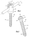
FIG. 1 is a perspective view of an exemplary multi-axial screw assembly according to the present teachings; -
FIG. 2 is a perspective view of an exemplary bone screw of the multi-axial screw assembly ofFIG. 1 ; -
FIGS. 3A and 3B are perspective views of a receiver for the multi-axial screw assembly ofFIG. 1 ; -
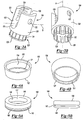
FIGS. 4A and 4B are perspective views of a sleeve for the multi-axial screw assembly ofFIG. 1 ; -
FIG. 5A is a perspective view of a cap for the multi-axial screw assembly ofFIG. 1 ; -
FIG. 5B is a side view of the cap ofFIG. 5A ; -
FIG. 6 is a perspective view of a cap-retaining ring for the multi- axial screw assembly ofFIG. 1 ; -
FIG. 7 is a perspective view of a bone screw ring for the multi- axial screw assembly ofFIG. 1 ; -
FIG. 8A is an exploded view of an exemplary multi-axial screw assembly according to the present teachings; -
FIGS. 8B-D illustrate various aspects of assembling the multi-axial screw assembly ofFIG. 8A ; -
FIG. 9 is a bottom perspective view of the multi-axial screw assembly ofFIG. 8D ; -
FIG. 10A is a side view of the multi-axial screw assembly ofFIG. 9 ; -
FIG. 10B is a sectional view of the multi-axial screw assembly ofFIG. 9 ; and -
FIG. 10C is an enlarged view ofDetail 10C ofFIG. 10B . - Referring to
FIG. 1 , an exemplary multi-axialbone fixation device 100 according to the present teachings is illustrated as assembled with a spinal connectingelement 109. Theconnecting element 109 is preferably in the form of a rod or bar or other elongated element. Although the connectingelement 109 is illustrated as straight, it will be appreciated that the connectingelement 109 preferably is curved and preferably has a curvature following, for example, the natural curvature of the spine. - Referring to
FIGS. 1 , 2 and8A , thebone fixation device 100 can generally include abone fastener 102, areceiver 104, a hollow retaining member orsleeve 106, anannular element 140 and first andsecond retention elements FIGS. 3A-7 and9-10C . - Referring to
FIG. 2 , thebone fastener 102 includes ahead 110 and a bone-engagingelongated portion 114 that preferably includes ridges, threads orother anchoring formations 116 along at least a portion of its length. Theelongated portion 114 includes one ormore cutting flutes 118 at its distal end. Thehead 110 of thebone fastener 102 defines a firstcircumferential groove 108 for at least partially receiving thefirst retention element 160. Thehead 110 includes aprotrusion 119 having an internal driver-engagement surface 112 for engaging a conventional or other insertion tool (not shown). Theengagement surface 112 preferably includes straight or curved drive faces. In the exemplary illustration ofFIG. 2 , a five-lobe (pentalobe)engagement surface 112 is shown for use with an insertion tool having complementary driver surfaces. - Referring to
FIGS. 3A and 3B , thereceiver 104 defines an axial opening comprising anupper opening 105 and alower opening 103 along a longitudinal axis A. Thereceiver 104 also includes anupper portion 121 comprising twoarms 120 and defining a U-shapedtransverse opening 101 along a transverse axis B. Each of thearms 120 definesinner engagement formations 128, such as threads, ridges, or grooves. Thetransverse opening 101 can be configured to receive a connecting element, such as the connectingelement 109 shown inFIG. 1 . Thereceiver 104 includes a radially compressiblelower portion 123 in the form of a socket defined by a plurality of spaced apart elongated elements orfingers 124. Eachelongated element 124 includes anoutward flange 126 directed radially away from thelower opening 103. Theelongated elements 124 preferably are resiliently deflected inward toward the longitudinal axis A for receiving thehollow member 106. - Referring to
FIGS. 4A and 4B , thehollow member 106 includes an annularupper face 130, an annularlower face 132, and aperipheral wall 134 between the upper andlower faces peripheral wall 134 is preferably tapered from theupper face 130 to thelower face 132, and defines an inner step or notch or othercircumferential discontinuity 131. Thehollow member 106 is insertably arranged around the compressiblelower portion 123 such that theflanges 126 engage thediscontinuity 131 and theelongated members 124 are urged radially inwards securing thehollow member 106 over thereceiver 104 in a snap-fit or other engagement. - Referring to
FIGS. 5A and 5B , theannular member 140 includes a peripheral orside wall 144 between upper andlower surfaces peripheral wall 144 defines anopening 117 through theannular member 140. Theannular member 140 preferably defines a second outercircumferential groove 142 on theperipheral wall 144 for at least partially receiving thesecond retention element 150. - Referring to
FIGS. 8A-8D , an exemplary procedure for assembling themulti-axial fixation device 100 includes assembling thefirst retention element 160 in the firstcircumferential groove 108 of thehead 110 of thebone fastener 102, as shown inFIG. 8B , and inserting thebone fastener 102 from thelower portion 123 of thereceiver 104 into thelower opening 103, as shown inFIG. 8C . As such, theelongated elements 124 in their relaxed states cooperate to define anopening 103 larger than the diameter of thehead 110. Thehollow member 106 is preferably pushed over thelower portion 123 until theflanges 126 of theelongated elements 124 snap into thediscontinuity 131 radially compressing thelower portion 123. Engagement of thehollow member 106 inwardly deflects theelongated elements 124 toward the first longitudinal axis A such that thelower opening 103 becomes smaller in diameter. The reduced diameter of thelower opening 103 is now smaller than the maximum diameter of thehead 110 and thereby prevents thehead 110 of thebone fastener 102 from becoming dislodged from thelower portion 123 of thereceiver 104, as shown inFIGS. 8C and9 . - As it is seen in
FIGS. 1 OB and C, a major diameter D of thehead 110 exceeds a minor diameter "d" of thereceiver 104. The minor diameter corresponds to theengagement formations 128. In this position, thefastener 102 angulates relative to the first longitudinal axis A of thereceiver 104, as shown inFIG. 8D in phantom lines. Thefirst retention element 160 provides frictional resistance to rotation of thebone fastener 102 relative to thereceiver 104. - Referring to
FIG. 8C , thesecond retention element 150 is assembled in the secondcircumferential groove 142 of theannular element 140, which is inserted from theupper portion 121 of thereceiver 104 and positioned to contact thehead 110 of thebone fastener 102, as shown inFIG. 8D . In one aspect, theannular member 140 is seated around theprotrusion 119 of thehead 110 of thebone fastener 102, such that theprotrusion 119 is inserted in theopening 117 defined by theperipheral wall 144. Thesecond retention element 150 retains theannular member 140 in thereceiver 104 and is supported between the secondcircumferential groove 142 and anotch 170 defined in an abutting inner surface of thereceiver 104, as shown inFIGS. 10B and 10C . - Referring to
FIGS. 1 and3A , after theannular element 140 is assembled in thereceiver 104, the connectingelement 109 is inserted along the transverse axis B in thetransverse opening 101 of thereceiver 104. A securing or lockingmember 113, in the form of a set screw or other plug, for example, is inserted through theupper opening 105 of thereceiver 104. The securingmember 113 preferably includesengagement formations 111 complimentary to theengagement formations 128 of thereceiver 104, and a driver-receivinginner surface 107. Theengagement formations 111 preferably comprise a helical flange, for example. A driver is preferably coupled to the driver- receivingsurface 107 and rotated to drive the securingmember 113 against the connectingelement 109, thereby transmitting compression through theannular element 140 to thehead 110 of thebone fastener 102 and securing thebone fastener 102 in a preselected angulation position. - The multi-axial
bone fixation device 100 is preferably used withbone fasteners 102 having different sizes or shapes, or of different types, with or withoutflutes 118 or other cutting ridges. For example, the extent and/or type of anchoringformations 116 can be varied, as well as the size and geometry of thehead 110, etc. - It will be appreciated that the present teachings allow quick loading of the
bone fastener 102 from thelower portion 123 of the receiver and still maintain a high degree of angulation similar to top-loading bone fasteners. Further, the present teachings allow a major diameter D of the head of thebone fastener 102 to exceed a minor diameter d that is associated with theengagement formations 128 for the securingelement 113. Thus the present teaching can prevent bone fastener back out.
Claims (12)
- A multi-axial bone fixation device comprising:a receiver (104) defining an axial opening along a longitudinal axis (A), the receiver (104) having first and second portions (121, 123) along the longitudinal axis (A), the second portion (123) being radially compressible;a bone fastener (102) having a head (110), the head (110) insertable into the axial opening in a direction from the second portion (123) to the first portion (121);a hollow member (106) received around the second portion (123), the hollow member (106) compressing the second portion (123) and retaining the head (110) while allowing angulation of the fastener (102) relative to the longitudinal axis (A) and a first retention ring (160) in a first circumferential groove (108) of the head (110) of the fastener (102), the first retention ring (160) providing frictional resistance to rotation and maintaining a position of the fastener (102) relative to the receiver (104) before implantation,wherein the second portion (123) comprises deflectable fingers (124) including outward flanges (126), and the hollow member (106) comprises a discontinuity (131) into which discontinuity the flanges of the fingers can snap-in.
- The device of claim 1, wherein the hollow member comprises a tapered inner surface.
- The device of claim 1, wherein the head (110) comprises a circumferential groove (108), the first ring at least partially disposed in the circumferential groove (108).
- The device of claim 1, further comprising an annular element (140) insertable into the axial opening in a direction from the first portion (121) to the second portion (123) and positioned in contact with the head (110) of the bone fastener (102).
- The device of claim 4, wherein the head (110) of the bone fastener (102) comprises an internal driver engagement surface (112).
- The device of claim 4, further comprising a second ring carried by the annular element (140), wherein the second ring secures the annular element (140) within the axial opening of the receiver (104).
- The device of claim 6, further comprising a threaded member, the threaded member threadably received into the first portion (121) of the receiver (104), the threaded member holding the fastener (102) in a fixed angle relative to the axial opening.
- The device of claim 7, wherein the threaded member contacts an elongated element received in a transverse opening (101) of the receiver (104) between the threaded member and the annular element (140).
- The device of claim 1, wherein the head (110) of the bone fastener (102) comprises an internal driver-engagement surface (112).
- The device of claim 1, wherein the second portion (123) comprises a plurality of spaced apart elements (124).
- The device of claim 10, wherein each of the spaced apart elements (124) includes an outer flange (126) extending proximate a distal end thereof.
- The device of claim 11, wherein the hollow member (106) comprises an inner circumferential discontinuity (131) engaging the outer flanges (126) of the spaced apart elements (124).
Applications Claiming Priority (2)
| Application Number | Priority Date | Filing Date | Title |
|---|---|---|---|
| US11/594,316 US7699876B2 (en) | 2006-11-08 | 2006-11-08 | Multi-axial bone fixation apparatus |
| PCT/US2007/023423 WO2008057551A2 (en) | 2006-11-08 | 2007-11-07 | Multi-axial bone fixation apparatus |
Publications (2)
| Publication Number | Publication Date |
|---|---|
| EP2097025A2 EP2097025A2 (en) | 2009-09-09 |
| EP2097025B1 true EP2097025B1 (en) | 2015-07-22 |
Family
ID=39205293
Family Applications (1)
| Application Number | Title | Priority Date | Filing Date |
|---|---|---|---|
| EP07861779.2A Active EP2097025B1 (en) | 2006-11-08 | 2007-11-07 | Multi-axial bone fixation apparatus |
Country Status (3)
| Country | Link |
|---|---|
| US (1) | US7699876B2 (en) |
| EP (1) | EP2097025B1 (en) |
| WO (1) | WO2008057551A2 (en) |
Families Citing this family (124)
| Publication number | Priority date | Publication date | Assignee | Title |
|---|---|---|---|---|
| US7833250B2 (en) | 2004-11-10 | 2010-11-16 | Jackson Roger P | Polyaxial bone screw with helically wound capture connection |
| US8353932B2 (en) | 2005-09-30 | 2013-01-15 | Jackson Roger P | Polyaxial bone anchor assembly with one-piece closure, pressure insert and plastic elongate member |
| US10729469B2 (en) | 2006-01-09 | 2020-08-04 | Roger P. Jackson | Flexible spinal stabilization assembly with spacer having off-axis core member |
| US8292926B2 (en) | 2005-09-30 | 2012-10-23 | Jackson Roger P | Dynamic stabilization connecting member with elastic core and outer sleeve |
| US10258382B2 (en) | 2007-01-18 | 2019-04-16 | Roger P. Jackson | Rod-cord dynamic connection assemblies with slidable bone anchor attachment members along the cord |
| US7862587B2 (en) | 2004-02-27 | 2011-01-04 | Jackson Roger P | Dynamic stabilization assemblies, tool set and method |
| US8876868B2 (en) | 2002-09-06 | 2014-11-04 | Roger P. Jackson | Helical guide and advancement flange with radially loaded lip |
| US7621918B2 (en) | 2004-11-23 | 2009-11-24 | Jackson Roger P | Spinal fixation tool set and method |
| US7377923B2 (en) | 2003-05-22 | 2008-05-27 | Alphatec Spine, Inc. | Variable angle spinal screw assembly |
| US7776067B2 (en) | 2005-05-27 | 2010-08-17 | Jackson Roger P | Polyaxial bone screw with shank articulation pressure insert and method |
| US8137386B2 (en) | 2003-08-28 | 2012-03-20 | Jackson Roger P | Polyaxial bone screw apparatus |
| US8377102B2 (en) | 2003-06-18 | 2013-02-19 | Roger P. Jackson | Polyaxial bone anchor with spline capture connection and lower pressure insert |
| US20110040338A1 (en) * | 2003-08-28 | 2011-02-17 | Jackson Roger P | Polyaxial bone anchor having an open retainer with conical, cylindrical or curvate capture |
| US8398682B2 (en) | 2003-06-18 | 2013-03-19 | Roger P. Jackson | Polyaxial bone screw assembly |
| US8926670B2 (en) | 2003-06-18 | 2015-01-06 | Roger P. Jackson | Polyaxial bone screw assembly |
| US7766915B2 (en) | 2004-02-27 | 2010-08-03 | Jackson Roger P | Dynamic fixation assemblies with inner core and outer coil-like member |
| US7967850B2 (en) | 2003-06-18 | 2011-06-28 | Jackson Roger P | Polyaxial bone anchor with helical capture connection, insert and dual locking assembly |
| US11419642B2 (en) | 2003-12-16 | 2022-08-23 | Medos International Sarl | Percutaneous access devices and bone anchor assemblies |
| US7179261B2 (en) | 2003-12-16 | 2007-02-20 | Depuy Spine, Inc. | Percutaneous access devices and bone anchor assemblies |
| US7527638B2 (en) | 2003-12-16 | 2009-05-05 | Depuy Spine, Inc. | Methods and devices for minimally invasive spinal fixation element placement |
| JP2007525274A (en) | 2004-02-27 | 2007-09-06 | ロジャー・ピー・ジャクソン | Orthopedic implant rod reduction instrument set and method |
| US11241261B2 (en) | 2005-09-30 | 2022-02-08 | Roger P Jackson | Apparatus and method for soft spinal stabilization using a tensionable cord and releasable end structure |
| US7160300B2 (en) | 2004-02-27 | 2007-01-09 | Jackson Roger P | Orthopedic implant rod reduction tool set and method |
| US8152810B2 (en) | 2004-11-23 | 2012-04-10 | Jackson Roger P | Spinal fixation tool set and method |
| US20050234457A1 (en) * | 2004-03-26 | 2005-10-20 | Anthony James | Methods for treating fractures of the femur and femoral fracture devices |
| US7651502B2 (en) | 2004-09-24 | 2010-01-26 | Jackson Roger P | Spinal fixation tool set and method for rod reduction and fastener insertion |
| US20060161152A1 (en) * | 2004-10-25 | 2006-07-20 | Alphaspine, Inc. | Bone fixation systems and methods of assembling and/or installing the same |
| JP2008519656A (en) | 2004-11-10 | 2008-06-12 | ロジャー・ピー・ジャクソン | Helical guide and forward flange with break extension |
| US8926672B2 (en) | 2004-11-10 | 2015-01-06 | Roger P. Jackson | Splay control closure for open bone anchor |
| US8308782B2 (en) | 2004-11-23 | 2012-11-13 | Jackson Roger P | Bone anchors with longitudinal connecting member engaging inserts and closures for fixation and optional angulation |
| US9168069B2 (en) | 2009-06-15 | 2015-10-27 | Roger P. Jackson | Polyaxial bone anchor with pop-on shank and winged insert with lower skirt for engaging a friction fit retainer |
| WO2006057837A1 (en) | 2004-11-23 | 2006-06-01 | Jackson Roger P | Spinal fixation tool attachment structure |
| US9980753B2 (en) | 2009-06-15 | 2018-05-29 | Roger P Jackson | pivotal anchor with snap-in-place insert having rotation blocking extensions |
| US8444681B2 (en) | 2009-06-15 | 2013-05-21 | Roger P. Jackson | Polyaxial bone anchor with pop-on shank, friction fit retainer and winged insert |
| US9216041B2 (en) | 2009-06-15 | 2015-12-22 | Roger P. Jackson | Spinal connecting members with tensioned cords and rigid sleeves for engaging compression inserts |
| US10076361B2 (en) | 2005-02-22 | 2018-09-18 | Roger P. Jackson | Polyaxial bone screw with spherical capture, compression and alignment and retention structures |
| US7901437B2 (en) | 2007-01-26 | 2011-03-08 | Jackson Roger P | Dynamic stabilization member with molded connection |
| US7955358B2 (en) | 2005-09-19 | 2011-06-07 | Albert Todd J | Bone screw apparatus, system and method |
| US8105368B2 (en) | 2005-09-30 | 2012-01-31 | Jackson Roger P | Dynamic stabilization connecting member with slitted core and outer sleeve |
| US7833252B2 (en) * | 2006-01-27 | 2010-11-16 | Warsaw Orthopedic, Inc. | Pivoting joints for spinal implants including designed resistance to motion and methods of use |
| US8057519B2 (en) | 2006-01-27 | 2011-11-15 | Warsaw Orthopedic, Inc. | Multi-axial screw assembly |
| US7722652B2 (en) | 2006-01-27 | 2010-05-25 | Warsaw Orthopedic, Inc. | Pivoting joints for spinal implants including designed resistance to motion and methods of use |
| WO2008008511A2 (en) * | 2006-07-14 | 2008-01-17 | Laszlo Garamszegi | Pedicle screw assembly with inclined surface seat |
| WO2008073323A2 (en) | 2006-12-08 | 2008-06-19 | Jackson Roger P | Tool system for dynamic spinal implants |
| US8366745B2 (en) | 2007-05-01 | 2013-02-05 | Jackson Roger P | Dynamic stabilization assembly having pre-compressed spacers with differential displacements |
| US8475498B2 (en) | 2007-01-18 | 2013-07-02 | Roger P. Jackson | Dynamic stabilization connecting member with cord connection |
| US10792074B2 (en) | 2007-01-22 | 2020-10-06 | Roger P. Jackson | Pivotal bone anchor assemly with twist-in-place friction fit insert |
| US10383660B2 (en) | 2007-05-01 | 2019-08-20 | Roger P. Jackson | Soft stabilization assemblies with pretensioned cords |
| EP2022423B1 (en) | 2007-07-31 | 2010-07-14 | BIEDERMANN MOTECH GmbH | Bone anchoring device |
| US20090069852A1 (en) * | 2007-09-06 | 2009-03-12 | Warsaw Orthopedic, Inc. | Multi-Axial Bone Anchor Assembly |
| US20090082812A1 (en) * | 2007-09-21 | 2009-03-26 | Lewis Trevor K | Provisional locking pedicle screw system and method |
| US8007522B2 (en) | 2008-02-04 | 2011-08-30 | Depuy Spine, Inc. | Methods for correction of spinal deformities |
| JP2012529969A (en) | 2008-08-01 | 2012-11-29 | ロジャー・ピー・ジャクソン | Longitudinal connecting member with tensioning cord with sleeve |
| JP2010099293A (en) * | 2008-10-24 | 2010-05-06 | Japan Medical Materials Corp | Bone anchor unit for vertebral column fixation and method for manufacturing the same |
| US8603145B2 (en) * | 2008-12-16 | 2013-12-10 | Zimmer Spine, Inc. | Coaxially lockable poly-axial bone fastener assemblies |
| EP2201902B1 (en) * | 2008-12-23 | 2011-10-19 | Biedermann Motech GmbH | Receiving part for receiving a rod for coupling the rod to a bone anchoring element and a bone anchoring device with such a receiving part |
| EP2204129B1 (en) * | 2008-12-30 | 2011-11-30 | Biedermann Motech GmbH | Receiving part for receiving a rod for coupling the rod to a bone anchoring element and a bone anchoring device with such a receiving part |
| FR2942951B1 (en) * | 2009-03-12 | 2012-03-30 | Euros Sa | SPINAL IMPLANT WITH LOCKING BALL JOINT |
| EP2753252A1 (en) | 2009-06-15 | 2014-07-16 | Jackson, Roger P. | Polyaxial bone anchor with pop-on shank and friction fit retainer with low profile edge lock |
| US11229457B2 (en) | 2009-06-15 | 2022-01-25 | Roger P. Jackson | Pivotal bone anchor assembly with insert tool deployment |
| US9668771B2 (en) | 2009-06-15 | 2017-06-06 | Roger P Jackson | Soft stabilization assemblies with off-set connector |
| US8998959B2 (en) | 2009-06-15 | 2015-04-07 | Roger P Jackson | Polyaxial bone anchors with pop-on shank, fully constrained friction fit retainer and lock and release insert |
| CN103826560A (en) | 2009-06-15 | 2014-05-28 | 罗杰.P.杰克逊 | Polyaxial bone anchor with pop-on shank and winged insert with friction fit compressive collet |
| ES2496178T3 (en) * | 2009-08-20 | 2014-09-18 | Biedermann Technologies Gmbh & Co. Kg | Bone anchoring device |
| CA2774471A1 (en) | 2009-10-05 | 2011-04-14 | James L. Surber | Polyaxial bone anchor with non-pivotable retainer and pop-on shank, some with friction fit |
| US20110106181A1 (en) * | 2009-10-30 | 2011-05-05 | Warsaw Orthopedic, Inc. | Adjustable saddle for a bone anchor |
| US8449578B2 (en) * | 2009-11-09 | 2013-05-28 | Ebi, Llc | Multiplanar bone anchor system |
| US9044272B2 (en) | 2009-11-09 | 2015-06-02 | Ebi, Llc | Multiplanar bone anchor system |
| US20110202094A1 (en) * | 2009-11-11 | 2011-08-18 | Pereira Mario L | Trans-polyaxial screw |
| ES2394774T3 (en) | 2010-05-05 | 2013-02-05 | Biedermann Technologies Gmbh & Co. Kg | Receiver piece intended to receive a bar for coupling with an anchoring element for bone, anchoring device for bone and method and tool for mounting it |
| WO2012030712A1 (en) * | 2010-08-30 | 2012-03-08 | Zimmer Spine, Inc. | Polyaxial pedicle screw |
| AU2011299558A1 (en) | 2010-09-08 | 2013-05-02 | Roger P. Jackson | Dynamic stabilization members with elastic and inelastic sections |
| DE112011103644T5 (en) * | 2010-11-02 | 2013-12-24 | Roger P. Jackson | Polyaxial bone anchor with quick-release shaft and rotatable holder |
| ES2534940T3 (en) * | 2010-12-10 | 2015-04-30 | Biedermann Technologies Gmbh & Co. Kg | Receiver piece for receiving a rod in order to couple it to a bone anchoring element, and bone anchoring element with such a receiving piece |
| ES2534968T3 (en) * | 2010-12-10 | 2015-04-30 | Biedermann Technologies Gmbh & Co. Kg | Bone anchoring device |
| US8992579B1 (en) | 2011-03-08 | 2015-03-31 | Nuvasive, Inc. | Lateral fixation constructs and related methods |
| WO2012128825A1 (en) | 2011-03-24 | 2012-09-27 | Jackson Roger P | Polyaxial bone anchor with compound articulation and pop-on shank |
| US9066734B2 (en) | 2011-08-31 | 2015-06-30 | Biomet Manufacturing, Llc | Patient-specific sacroiliac guides and associated methods |
| US9295497B2 (en) | 2011-08-31 | 2016-03-29 | Biomet Manufacturing, Llc | Patient-specific sacroiliac and pedicle guides |
| ES2558083T3 (en) | 2011-09-30 | 2016-02-01 | Biedermann Technologies Gmbh & Co. Kg | Bone anchoring device and tool that cooperates with said bone anchoring device |
| EP2747670A4 (en) | 2011-10-05 | 2015-06-24 | Mark A Dodson | Modular retractor and related method |
| US8663291B2 (en) | 2011-10-28 | 2014-03-04 | Ortho Innovations, Llc | Top loading polyaxial ball and socket fastener |
| US8911479B2 (en) | 2012-01-10 | 2014-12-16 | Roger P. Jackson | Multi-start closures for open implants |
| US9060815B1 (en) | 2012-03-08 | 2015-06-23 | Nuvasive, Inc. | Systems and methods for performing spine surgery |
| EP2682062B1 (en) * | 2012-07-03 | 2015-09-16 | Biedermann Technologies GmbH & Co. KG | Polyaxial bone anchoring device |
| EP2687171B1 (en) | 2012-07-18 | 2015-04-22 | Biedermann Technologies GmbH & Co. KG | Polyaxial bone anchoring device |
| US9782204B2 (en) | 2012-09-28 | 2017-10-10 | Medos International Sarl | Bone anchor assemblies |
| US8911478B2 (en) | 2012-11-21 | 2014-12-16 | Roger P. Jackson | Splay control closure for open bone anchor |
| US10058354B2 (en) | 2013-01-28 | 2018-08-28 | Roger P. Jackson | Pivotal bone anchor assembly with frictional shank head seating surfaces |
| US8852239B2 (en) | 2013-02-15 | 2014-10-07 | Roger P Jackson | Sagittal angle screw with integral shank and receiver |
| US20140277203A1 (en) | 2013-03-14 | 2014-09-18 | Ebi, Llc | Torque multiplier, limiter, and counter-torque combinations and methods |
| US20140277153A1 (en) | 2013-03-14 | 2014-09-18 | DePuy Synthes Products, LLC | Bone Anchor Assemblies and Methods With Improved Locking |
| US9775660B2 (en) | 2013-03-14 | 2017-10-03 | DePuy Synthes Products, Inc. | Bottom-loading bone anchor assemblies and methods |
| US9259247B2 (en) | 2013-03-14 | 2016-02-16 | Medos International Sarl | Locking compression members for use with bone anchor assemblies and methods |
| US10342582B2 (en) | 2013-03-14 | 2019-07-09 | DePuy Synthes Products, Inc. | Bone anchor assemblies and methods with improved locking |
| US9724145B2 (en) | 2013-03-14 | 2017-08-08 | Medos International Sarl | Bone anchor assemblies with multiple component bottom loading bone anchors |
| US9987047B2 (en) | 2013-10-07 | 2018-06-05 | Spine Wave, Inc. | Translating polyaxial screw |
| US9517089B1 (en) | 2013-10-08 | 2016-12-13 | Nuvasive, Inc. | Bone anchor with offset rod connector |
| US9566092B2 (en) * | 2013-10-29 | 2017-02-14 | Roger P. Jackson | Cervical bone anchor with collet retainer and outer locking sleeve |
| US9717533B2 (en) | 2013-12-12 | 2017-08-01 | Roger P. Jackson | Bone anchor closure pivot-splay control flange form guide and advancement structure |
| US9498255B2 (en) * | 2013-12-31 | 2016-11-22 | Blackstone Medical, Inc. | Translational pedicle screw systems |
| US9451993B2 (en) | 2014-01-09 | 2016-09-27 | Roger P. Jackson | Bi-radial pop-on cervical bone anchor |
| US10064658B2 (en) | 2014-06-04 | 2018-09-04 | Roger P. Jackson | Polyaxial bone anchor with insert guides |
| US9597119B2 (en) | 2014-06-04 | 2017-03-21 | Roger P. Jackson | Polyaxial bone anchor with polymer sleeve |
| US9707013B2 (en) * | 2015-04-30 | 2017-07-18 | Warsaw Orthopedic, Inc. | Spinal implant system and methods of use |
| JP6965257B2 (en) | 2016-02-26 | 2021-11-10 | メドス・インターナショナル・エスエイアールエルMedos International SARL | Multi-axis bone fixation element |
| EP3278750B1 (en) * | 2016-08-04 | 2018-12-12 | Biedermann Technologies GmbH & Co. KG | Polyaxial bone anchoring device and system of an instrument and a polyaxial bone anchoring device |
| EP3287089B1 (en) * | 2016-08-24 | 2019-07-24 | Biedermann Technologies GmbH & Co. KG | Polyaxial bone anchoring device and system of an instrument and a polyaxial bone anchoring device |
| US11026730B2 (en) * | 2017-05-10 | 2021-06-08 | Medos International Sarl | Bone anchors with drag features and related methods |
| US10258386B2 (en) * | 2017-06-15 | 2019-04-16 | Warsaw Orthopedic, Inc. | Spinal construct and method |
| US10610265B1 (en) | 2017-07-31 | 2020-04-07 | K2M, Inc. | Polyaxial bone screw with increased angulation |
| EP3476340B1 (en) | 2017-10-25 | 2021-06-02 | Biedermann Technologies GmbH & Co. KG | Polyaxial bone anchoring device |
| US10695102B2 (en) * | 2017-12-15 | 2020-06-30 | Warsaw Orthopedic, Inc. | Spinal implant system and methods of use |
| US10695100B2 (en) * | 2017-12-15 | 2020-06-30 | Warsaw Orthopedic, Inc. | Spinal implant system and methods of use |
| EP3536271B1 (en) | 2018-03-06 | 2022-05-04 | Biedermann Technologies GmbH & Co. KG | Polyaxial bone anchoring device and system of an instrument and a polyaxial bone anchoring device |
| US10898232B2 (en) | 2018-03-20 | 2021-01-26 | Medos International Sàrl | Multipoint fixation implants and related methods |
| US10687858B2 (en) | 2018-11-08 | 2020-06-23 | Warsaw Orthopedic, Inc. | Spinal implant system and methods of use |
| US10918421B2 (en) * | 2019-05-07 | 2021-02-16 | Warsaw Orthopedic, Inc. | Spinal implant system and methods of use |
| US11141197B2 (en) * | 2019-06-24 | 2021-10-12 | DePuy Synthes Products, Inc. | Polyaxial strut for external fixation |
| US11426210B2 (en) | 2019-09-25 | 2022-08-30 | Medos International Sàrl | Multipoint angled fixation implants for multiple screws and related methods |
| EP3821834B1 (en) * | 2019-11-14 | 2024-05-01 | Biedermann Technologies GmbH & Co. KG | Receiving part for coupling a rod to a bone anchor |
| JP2023514243A (en) * | 2020-02-14 | 2023-04-05 | メドス・インターナショナル・エスエイアールエル | Integrated multi-point fixing screw |
| US11376046B1 (en) | 2021-02-01 | 2022-07-05 | Warsaw Orthopedic, Inc. | Spinal implant system and method |
| EP4129220A1 (en) * | 2021-08-04 | 2023-02-08 | Biedermann Technologies GmbH & Co. KG | Coupling device for coupling a rod to a bone anchoring element and method of manufacturing the same |
Family Cites Families (23)
| Publication number | Priority date | Publication date | Assignee | Title |
|---|---|---|---|---|
| DE3614101C1 (en) | 1986-04-25 | 1987-10-22 | Juergen Prof Dr Med Harms | Pedicle screw |
| US5669911A (en) | 1995-04-13 | 1997-09-23 | Fastenetix, L.L.C. | Polyaxial pedicle screw |
| US5733285A (en) | 1995-07-13 | 1998-03-31 | Fastenetix, Llc | Polyaxial locking mechanism |
| US5549608A (en) | 1995-07-13 | 1996-08-27 | Fastenetix, L.L.C. | Advanced polyaxial locking screw and coupling element device for use with rod fixation apparatus |
| US5964760A (en) | 1996-10-18 | 1999-10-12 | Spinal Innovations | Spinal implant fixation assembly |
| US5728098A (en) | 1996-11-07 | 1998-03-17 | Sdgi Holdings, Inc. | Multi-angle bone screw assembly using shape-memory technology |
| EP0954247B1 (en) | 1997-01-22 | 2005-11-23 | Synthes Ag Chur | Device for connecting a longitudinal bar to a pedicle screw |
| US6010503A (en) | 1998-04-03 | 2000-01-04 | Spinal Innovations, Llc | Locking mechanism |
| PT1117336E (en) * | 1998-09-29 | 2004-10-29 | Synthes Ag | DEVICE FOR CONNECTING A LONGITUDINAL SUPPORT TO A BONUS FIXATION MEANS |
| US6273888B1 (en) * | 1999-05-28 | 2001-08-14 | Sdgi Holdings, Inc. | Device and method for selectively preventing the locking of a shape-memory alloy coupling system |
| US6254602B1 (en) | 1999-05-28 | 2001-07-03 | Sdgi Holdings, Inc. | Advanced coupling device using shape-memory technology |
| US6280442B1 (en) * | 1999-09-01 | 2001-08-28 | Sdgi Holdings, Inc. | Multi-axial bone screw assembly |
| US7066937B2 (en) * | 2002-02-13 | 2006-06-27 | Endius Incorporated | Apparatus for connecting a longitudinal member to a bone portion |
| US20060200128A1 (en) | 2003-04-04 | 2006-09-07 | Richard Mueller | Bone anchor |
| WO2005018471A1 (en) | 2003-08-20 | 2005-03-03 | Sdgi Holdings, Inc. | Multi-axial orthopedic device and system, e.g. for spinal surgery |
| US20050080415A1 (en) * | 2003-10-14 | 2005-04-14 | Keyer Thomas R. | Polyaxial bone anchor and method of spinal fixation |
| US7090674B2 (en) | 2003-11-03 | 2006-08-15 | Spinal, Llc | Bone fixation system with low profile fastener |
| US20050251192A1 (en) | 2004-03-31 | 2005-11-10 | Shluzas Alan E | Access device having discrete visualization locations |
| US8475495B2 (en) | 2004-04-08 | 2013-07-02 | Globus Medical | Polyaxial screw |
| US7491207B2 (en) | 2004-04-12 | 2009-02-17 | Synthes Usa, Llc | Rod persuader |
| US20060161152A1 (en) | 2004-10-25 | 2006-07-20 | Alphaspine, Inc. | Bone fixation systems and methods of assembling and/or installing the same |
| US7674277B2 (en) | 2004-12-01 | 2010-03-09 | Warsaw Orthopedic, Inc. | Side-loading bone anchor |
| US20070118117A1 (en) | 2005-10-20 | 2007-05-24 | Ebi, L.P. | Bone fixation assembly |
-
2006
- 2006-11-08 US US11/594,316 patent/US7699876B2/en active Active
-
2007
- 2007-11-07 EP EP07861779.2A patent/EP2097025B1/en active Active
- 2007-11-07 WO PCT/US2007/023423 patent/WO2008057551A2/en active Application Filing
Also Published As
| Publication number | Publication date |
|---|---|
| US20080108992A1 (en) | 2008-05-08 |
| US7699876B2 (en) | 2010-04-20 |
| WO2008057551A3 (en) | 2008-07-03 |
| EP2097025A2 (en) | 2009-09-09 |
| WO2008057551A2 (en) | 2008-05-15 |
Similar Documents
| Publication | Publication Date | Title |
|---|---|---|
| EP2097025B1 (en) | Multi-axial bone fixation apparatus | |
| US9936979B2 (en) | Bone anchor with locking cap and method of spinal fixation | |
| US9924974B2 (en) | Polyaxial bone anchoring device | |
| EP2851021B1 (en) | Coupling assembly for coupling a rod to a bone anchoring element, polyaxial bone anchoring device and modular stabilization device | |
| US9603641B2 (en) | Device for osteosynthesis | |
| EP2893890B1 (en) | Coupling assembly for coupling a rod to a bone anchoring element, and polyaxial bone anchoring device | |
| US6224598B1 (en) | Bone screw threaded plug closure with central set screw | |
| US6569164B1 (en) | Spinal osteosynthesis system for anterior fixation | |
| US8506609B2 (en) | Receiving part for receiving a rod for coupling the rod to a bone anchoring element and a bone anchoring device with such a receiving part | |
| US6613053B1 (en) | Surgical implant | |
| JP5613401B2 (en) | Receiving part for receiving the rod and connecting it to the bone anchoring element, and a bone anchoring device having such a receiving part | |
| JP5957216B2 (en) | Bone anchoring device | |
| US20040267264A1 (en) | Polyaxial bone screw | |
| EP2674123B1 (en) | Polyaxial bone anchoring device | |
| EP2410931A1 (en) | Variable height, multi-axial bone screw assembly | |
| EP3536271B1 (en) | Polyaxial bone anchoring device and system of an instrument and a polyaxial bone anchoring device | |
| JP7343717B2 (en) | modular tension spinal screw | |
| CN114052879A (en) | Bone anchoring device |
Legal Events
| Date | Code | Title | Description |
|---|---|---|---|
| PUAI | Public reference made under article 153(3) epc to a published international application that has entered the european phase |
Free format text: ORIGINAL CODE: 0009012 |
|
| 17P | Request for examination filed |
Effective date: 20090608 |
|
| AK | Designated contracting states |
Kind code of ref document: A2 Designated state(s): AT BE BG CH CY CZ DE DK EE ES FI FR GB GR HU IE IS IT LI LT LU LV MC MT NL PL PT RO SE SI SK TR |
|
| RAP1 | Party data changed (applicant data changed or rights of an application transferred) |
Owner name: EBI, LLC |
|
| DAX | Request for extension of the european patent (deleted) | ||
| 17Q | First examination report despatched |
Effective date: 20120615 |
|
| GRAP | Despatch of communication of intention to grant a patent |
Free format text: ORIGINAL CODE: EPIDOSNIGR1 |
|
| INTG | Intention to grant announced |
Effective date: 20150217 |
|
| GRAS | Grant fee paid |
Free format text: ORIGINAL CODE: EPIDOSNIGR3 |
|
| GRAA | (expected) grant |
Free format text: ORIGINAL CODE: 0009210 |
|
| AK | Designated contracting states |
Kind code of ref document: B1 Designated state(s): AT BE BG CH CY CZ DE DK EE ES FI FR GB GR HU IE IS IT LI LT LU LV MC MT NL PL PT RO SE SI SK TR |
|
| REG | Reference to a national code |
Ref country code: GB Ref legal event code: FG4D |
|
| REG | Reference to a national code |
Ref country code: CH Ref legal event code: EP |
|
| REG | Reference to a national code |
Ref country code: IE Ref legal event code: FG4D |
|
| REG | Reference to a national code |
Ref country code: AT Ref legal event code: REF Ref document number: 737419 Country of ref document: AT Kind code of ref document: T Effective date: 20150815 |
|
| REG | Reference to a national code |
Ref country code: DE Ref legal event code: R096 Ref document number: 602007042295 Country of ref document: DE |
|
| REG | Reference to a national code |
Ref country code: FR Ref legal event code: PLFP Year of fee payment: 9 |
|
| REG | Reference to a national code |
Ref country code: CH Ref legal event code: NV Representative=s name: OFFICE ERNEST T. FREYLINGER S.A., CH |
|
| REG | Reference to a national code |
Ref country code: AT Ref legal event code: MK05 Ref document number: 737419 Country of ref document: AT Kind code of ref document: T Effective date: 20150722 |
|
| REG | Reference to a national code |
Ref country code: LT Ref legal event code: MG4D |
|
| REG | Reference to a national code |
Ref country code: NL Ref legal event code: MP Effective date: 20150722 |
|
| PG25 | Lapsed in a contracting state [announced via postgrant information from national office to epo] |
Ref country code: LV Free format text: LAPSE BECAUSE OF FAILURE TO SUBMIT A TRANSLATION OF THE DESCRIPTION OR TO PAY THE FEE WITHIN THE PRESCRIBED TIME-LIMIT Effective date: 20150722 Ref country code: LT Free format text: LAPSE BECAUSE OF FAILURE TO SUBMIT A TRANSLATION OF THE DESCRIPTION OR TO PAY THE FEE WITHIN THE PRESCRIBED TIME-LIMIT Effective date: 20150722 Ref country code: GR Free format text: LAPSE BECAUSE OF FAILURE TO SUBMIT A TRANSLATION OF THE DESCRIPTION OR TO PAY THE FEE WITHIN THE PRESCRIBED TIME-LIMIT Effective date: 20151023 Ref country code: FI Free format text: LAPSE BECAUSE OF FAILURE TO SUBMIT A TRANSLATION OF THE DESCRIPTION OR TO PAY THE FEE WITHIN THE PRESCRIBED TIME-LIMIT Effective date: 20150722 |
|
| PG25 | Lapsed in a contracting state [announced via postgrant information from national office to epo] |
Ref country code: PL Free format text: LAPSE BECAUSE OF FAILURE TO SUBMIT A TRANSLATION OF THE DESCRIPTION OR TO PAY THE FEE WITHIN THE PRESCRIBED TIME-LIMIT Effective date: 20150722 Ref country code: IS Free format text: LAPSE BECAUSE OF FAILURE TO SUBMIT A TRANSLATION OF THE DESCRIPTION OR TO PAY THE FEE WITHIN THE PRESCRIBED TIME-LIMIT Effective date: 20151122 Ref country code: ES Free format text: LAPSE BECAUSE OF FAILURE TO SUBMIT A TRANSLATION OF THE DESCRIPTION OR TO PAY THE FEE WITHIN THE PRESCRIBED TIME-LIMIT Effective date: 20150722 Ref country code: SE Free format text: LAPSE BECAUSE OF FAILURE TO SUBMIT A TRANSLATION OF THE DESCRIPTION OR TO PAY THE FEE WITHIN THE PRESCRIBED TIME-LIMIT Effective date: 20150722 Ref country code: AT Free format text: LAPSE BECAUSE OF FAILURE TO SUBMIT A TRANSLATION OF THE DESCRIPTION OR TO PAY THE FEE WITHIN THE PRESCRIBED TIME-LIMIT Effective date: 20150722 Ref country code: PT Free format text: LAPSE BECAUSE OF FAILURE TO SUBMIT A TRANSLATION OF THE DESCRIPTION OR TO PAY THE FEE WITHIN THE PRESCRIBED TIME-LIMIT Effective date: 20151123 |
|
| REG | Reference to a national code |
Ref country code: DE Ref legal event code: R097 Ref document number: 602007042295 Country of ref document: DE |
|
| PG25 | Lapsed in a contracting state [announced via postgrant information from national office to epo] |
Ref country code: EE Free format text: LAPSE BECAUSE OF FAILURE TO SUBMIT A TRANSLATION OF THE DESCRIPTION OR TO PAY THE FEE WITHIN THE PRESCRIBED TIME-LIMIT Effective date: 20150722 Ref country code: CZ Free format text: LAPSE BECAUSE OF FAILURE TO SUBMIT A TRANSLATION OF THE DESCRIPTION OR TO PAY THE FEE WITHIN THE PRESCRIBED TIME-LIMIT Effective date: 20150722 Ref country code: SK Free format text: LAPSE BECAUSE OF FAILURE TO SUBMIT A TRANSLATION OF THE DESCRIPTION OR TO PAY THE FEE WITHIN THE PRESCRIBED TIME-LIMIT Effective date: 20150722 Ref country code: IT Free format text: LAPSE BECAUSE OF FAILURE TO SUBMIT A TRANSLATION OF THE DESCRIPTION OR TO PAY THE FEE WITHIN THE PRESCRIBED TIME-LIMIT Effective date: 20150722 Ref country code: DK Free format text: LAPSE BECAUSE OF FAILURE TO SUBMIT A TRANSLATION OF THE DESCRIPTION OR TO PAY THE FEE WITHIN THE PRESCRIBED TIME-LIMIT Effective date: 20150722 |
|
| PLBE | No opposition filed within time limit |
Free format text: ORIGINAL CODE: 0009261 |
|
| STAA | Information on the status of an ep patent application or granted ep patent |
Free format text: STATUS: NO OPPOSITION FILED WITHIN TIME LIMIT |
|
| PG25 | Lapsed in a contracting state [announced via postgrant information from national office to epo] |
Ref country code: RO Free format text: LAPSE BECAUSE OF FAILURE TO SUBMIT A TRANSLATION OF THE DESCRIPTION OR TO PAY THE FEE WITHIN THE PRESCRIBED TIME-LIMIT Effective date: 20150722 |
|
| 26N | No opposition filed |
Effective date: 20160425 |
|
| PG25 | Lapsed in a contracting state [announced via postgrant information from national office to epo] |
Ref country code: LU Free format text: LAPSE BECAUSE OF FAILURE TO SUBMIT A TRANSLATION OF THE DESCRIPTION OR TO PAY THE FEE WITHIN THE PRESCRIBED TIME-LIMIT Effective date: 20151107 Ref country code: MC Free format text: LAPSE BECAUSE OF FAILURE TO SUBMIT A TRANSLATION OF THE DESCRIPTION OR TO PAY THE FEE WITHIN THE PRESCRIBED TIME-LIMIT Effective date: 20150722 |
|
| PG25 | Lapsed in a contracting state [announced via postgrant information from national office to epo] |
Ref country code: SI Free format text: LAPSE BECAUSE OF FAILURE TO SUBMIT A TRANSLATION OF THE DESCRIPTION OR TO PAY THE FEE WITHIN THE PRESCRIBED TIME-LIMIT Effective date: 20150722 |
|
| REG | Reference to a national code |
Ref country code: FR Ref legal event code: PLFP Year of fee payment: 10 |
|
| PG25 | Lapsed in a contracting state [announced via postgrant information from national office to epo] |
Ref country code: BE Free format text: LAPSE BECAUSE OF FAILURE TO SUBMIT A TRANSLATION OF THE DESCRIPTION OR TO PAY THE FEE WITHIN THE PRESCRIBED TIME-LIMIT Effective date: 20150722 |
|
| PG25 | Lapsed in a contracting state [announced via postgrant information from national office to epo] |
Ref country code: BG Free format text: LAPSE BECAUSE OF FAILURE TO SUBMIT A TRANSLATION OF THE DESCRIPTION OR TO PAY THE FEE WITHIN THE PRESCRIBED TIME-LIMIT Effective date: 20150722 Ref country code: HU Free format text: LAPSE BECAUSE OF FAILURE TO SUBMIT A TRANSLATION OF THE DESCRIPTION OR TO PAY THE FEE WITHIN THE PRESCRIBED TIME-LIMIT; INVALID AB INITIO Effective date: 20071107 |
|
| PG25 | Lapsed in a contracting state [announced via postgrant information from national office to epo] |
Ref country code: NL Free format text: LAPSE BECAUSE OF FAILURE TO SUBMIT A TRANSLATION OF THE DESCRIPTION OR TO PAY THE FEE WITHIN THE PRESCRIBED TIME-LIMIT Effective date: 20150722 Ref country code: CY Free format text: LAPSE BECAUSE OF FAILURE TO SUBMIT A TRANSLATION OF THE DESCRIPTION OR TO PAY THE FEE WITHIN THE PRESCRIBED TIME-LIMIT Effective date: 20150722 |
|
| PG25 | Lapsed in a contracting state [announced via postgrant information from national office to epo] |
Ref country code: MT Free format text: LAPSE BECAUSE OF FAILURE TO SUBMIT A TRANSLATION OF THE DESCRIPTION OR TO PAY THE FEE WITHIN THE PRESCRIBED TIME-LIMIT Effective date: 20150722 Ref country code: TR Free format text: LAPSE BECAUSE OF FAILURE TO SUBMIT A TRANSLATION OF THE DESCRIPTION OR TO PAY THE FEE WITHIN THE PRESCRIBED TIME-LIMIT Effective date: 20150722 |
|
| REG | Reference to a national code |
Ref country code: FR Ref legal event code: PLFP Year of fee payment: 11 |
|
| REG | Reference to a national code |
Ref country code: CH Ref legal event code: NV Representative=s name: SCHNEIDER FELDMANN AG PATENT- UND MARKENANWAEL, CH Ref country code: CH Ref legal event code: PUE Owner name: ZIMMER BIOMET SPINE, INC., US Free format text: FORMER OWNER: EBI, LLC, US |
|
| REG | Reference to a national code |
Ref country code: GB Ref legal event code: 732E Free format text: REGISTERED BETWEEN 20171207 AND 20171213 |
|
| PGFP | Annual fee paid to national office [announced via postgrant information from national office to epo] |
Ref country code: FR Payment date: 20171012 Year of fee payment: 11 |
|
| PGFP | Annual fee paid to national office [announced via postgrant information from national office to epo] |
Ref country code: CH Payment date: 20171114 Year of fee payment: 11 Ref country code: IE Payment date: 20171109 Year of fee payment: 11 |
|
| REG | Reference to a national code |
Ref country code: FR Ref legal event code: TP Owner name: ZIMMER BIOMET SPINE, INC., US Effective date: 20180515 |
|
| REG | Reference to a national code |
Ref country code: CH Ref legal event code: PL |
|
| REG | Reference to a national code |
Ref country code: DE Ref document number: 602007042295 Country of ref document: DE Ref country code: DE Ref legal event code: R082 Ref document number: 602007042295 Country of ref document: DE Representative=s name: VENNER SHIPLEY LLP, CAMBRIDGE, GB |
|
| REG | Reference to a national code |
Ref country code: IE Ref legal event code: MM4A |
|
| PG25 | Lapsed in a contracting state [announced via postgrant information from national office to epo] |
Ref country code: CH Free format text: LAPSE BECAUSE OF NON-PAYMENT OF DUE FEES Effective date: 20181130 Ref country code: LI Free format text: LAPSE BECAUSE OF NON-PAYMENT OF DUE FEES Effective date: 20181130 |
|
| PG25 | Lapsed in a contracting state [announced via postgrant information from national office to epo] |
Ref country code: FR Free format text: LAPSE BECAUSE OF NON-PAYMENT OF DUE FEES Effective date: 20181130 Ref country code: IE Free format text: LAPSE BECAUSE OF NON-PAYMENT OF DUE FEES Effective date: 20181107 |
|
| REG | Reference to a national code |
Ref country code: DE Ref legal event code: R081 Ref document number: 602007042295 Country of ref document: DE Owner name: ZIMMER BIOMET SPINE, INC., BROOMFIELD, US Free format text: FORMER OWNER: EBI, LLC, PARSIPPANY, N.J., US Ref country code: DE Ref legal event code: R082 Ref document number: 602007042295 Country of ref document: DE Ref country code: DE Ref legal event code: R081 Ref document number: 602007042295 Country of ref document: DE Owner name: ZIMMER BIOMET SPINE, INC., WESTMINSTER, US Free format text: FORMER OWNER: EBI, LLC, PARSIPPANY, N.J., US |
|
| REG | Reference to a national code |
Ref country code: DE Ref legal event code: R081 Ref document number: 602007042295 Country of ref document: DE Owner name: ZIMMER BIOMET SPINE, INC., WESTMINSTER, US Free format text: FORMER OWNER: ZIMMER BIOMET SPINE, INC., BROOMFIELD, COL., US |
|
| PGFP | Annual fee paid to national office [announced via postgrant information from national office to epo] |
Ref country code: GB Payment date: 20201008 Year of fee payment: 14 |
|
| GBPC | Gb: european patent ceased through non-payment of renewal fee |
Effective date: 20211107 |
|
| PG25 | Lapsed in a contracting state [announced via postgrant information from national office to epo] |
Ref country code: GB Free format text: LAPSE BECAUSE OF NON-PAYMENT OF DUE FEES Effective date: 20211107 |
|
| PGFP | Annual fee paid to national office [announced via postgrant information from national office to epo] |
Ref country code: DE Payment date: 20220914 Year of fee payment: 16 |