EP2104474B1 - Knee joint prosthesis system - Google Patents
Knee joint prosthesis system Download PDFInfo
- Publication number
- EP2104474B1 EP2104474B1 EP08779545A EP08779545A EP2104474B1 EP 2104474 B1 EP2104474 B1 EP 2104474B1 EP 08779545 A EP08779545 A EP 08779545A EP 08779545 A EP08779545 A EP 08779545A EP 2104474 B1 EP2104474 B1 EP 2104474B1
- Authority
- EP
- European Patent Office
- Prior art keywords
- adapter
- stem
- component
- locking member
- augments
- Prior art date
- Legal status (The legal status is an assumption and is not a legal conclusion. Google has not performed a legal analysis and makes no representation as to the accuracy of the status listed.)
- Active
Links
- 210000000629 knee joint Anatomy 0.000 title claims description 30
- 210000003127 knee Anatomy 0.000 claims description 46
- 239000000463 material Substances 0.000 claims description 8
- 238000003780 insertion Methods 0.000 description 32
- 230000037431 insertion Effects 0.000 description 32
- 229910052751 metal Inorganic materials 0.000 description 14
- 239000002184 metal Substances 0.000 description 14
- 230000007704 transition Effects 0.000 description 9
- 239000000560 biocompatible material Substances 0.000 description 8
- 230000000087 stabilizing effect Effects 0.000 description 7
- 238000000034 method Methods 0.000 description 6
- 206010065687 Bone loss Diseases 0.000 description 5
- 210000000988 bone and bone Anatomy 0.000 description 5
- 239000007943 implant Substances 0.000 description 5
- 230000033001 locomotion Effects 0.000 description 5
- 239000007787 solid Substances 0.000 description 4
- 230000008878 coupling Effects 0.000 description 3
- 238000010168 coupling process Methods 0.000 description 3
- 238000005859 coupling reaction Methods 0.000 description 3
- 239000004696 Poly ether ether ketone Substances 0.000 description 2
- 229910001069 Ti alloy Inorganic materials 0.000 description 2
- 239000004699 Ultra-high molecular weight polyethylene Substances 0.000 description 2
- MTHLBYMFGWSRME-UHFFFAOYSA-N [Cr].[Co].[Mo] Chemical compound [Cr].[Co].[Mo] MTHLBYMFGWSRME-UHFFFAOYSA-N 0.000 description 2
- JUPQTSLXMOCDHR-UHFFFAOYSA-N benzene-1,4-diol;bis(4-fluorophenyl)methanone Chemical compound OC1=CC=C(O)C=C1.C1=CC(F)=CC=C1C(=O)C1=CC=C(F)C=C1 JUPQTSLXMOCDHR-UHFFFAOYSA-N 0.000 description 2
- 230000000295 complement effect Effects 0.000 description 2
- 230000006866 deterioration Effects 0.000 description 2
- 210000003041 ligament Anatomy 0.000 description 2
- 239000004033 plastic Substances 0.000 description 2
- 229920003023 plastic Polymers 0.000 description 2
- 229920002530 polyetherether ketone Polymers 0.000 description 2
- 229920000785 ultra high molecular weight polyethylene Polymers 0.000 description 2
- OKTJSMMVPCPJKN-UHFFFAOYSA-N Carbon Chemical compound [C] OKTJSMMVPCPJKN-UHFFFAOYSA-N 0.000 description 1
- 239000004698 Polyethylene Substances 0.000 description 1
- RTAQQCXQSZGOHL-UHFFFAOYSA-N Titanium Chemical compound [Ti] RTAQQCXQSZGOHL-UHFFFAOYSA-N 0.000 description 1
- 229920010741 Ultra High Molecular Weight Polyethylene (UHMWPE) Polymers 0.000 description 1
- 210000001264 anterior cruciate ligament Anatomy 0.000 description 1
- 230000000712 assembly Effects 0.000 description 1
- 238000000429 assembly Methods 0.000 description 1
- 229910052799 carbon Inorganic materials 0.000 description 1
- 239000000788 chromium alloy Substances 0.000 description 1
- 239000010941 cobalt Substances 0.000 description 1
- 229910017052 cobalt Inorganic materials 0.000 description 1
- GUTLYIVDDKVIGB-UHFFFAOYSA-N cobalt atom Chemical group [Co] GUTLYIVDDKVIGB-UHFFFAOYSA-N 0.000 description 1
- 210000004439 collateral ligament Anatomy 0.000 description 1
- 230000006835 compression Effects 0.000 description 1
- 238000007906 compression Methods 0.000 description 1
- 238000010276 construction Methods 0.000 description 1
- 230000000881 depressing effect Effects 0.000 description 1
- 230000002349 favourable effect Effects 0.000 description 1
- 210000001699 lower leg Anatomy 0.000 description 1
- 239000000203 mixture Substances 0.000 description 1
- 238000012986 modification Methods 0.000 description 1
- 230000004048 modification Effects 0.000 description 1
- 210000003205 muscle Anatomy 0.000 description 1
- -1 polyethylene Polymers 0.000 description 1
- 229920000573 polyethylene Polymers 0.000 description 1
- 210000002967 posterior cruciate ligament Anatomy 0.000 description 1
- 230000000717 retained effect Effects 0.000 description 1
- 238000000926 separation method Methods 0.000 description 1
- 210000004872 soft tissue Anatomy 0.000 description 1
- 239000010935 stainless steel Substances 0.000 description 1
- 229910001220 stainless steel Inorganic materials 0.000 description 1
- 210000002435 tendon Anatomy 0.000 description 1
- 210000002303 tibia Anatomy 0.000 description 1
- 239000010936 titanium Substances 0.000 description 1
- 229910052719 titanium Inorganic materials 0.000 description 1
- 210000000689 upper leg Anatomy 0.000 description 1
Images


Classifications
-
- A—HUMAN NECESSITIES
- A61—MEDICAL OR VETERINARY SCIENCE; HYGIENE
- A61F—FILTERS IMPLANTABLE INTO BLOOD VESSELS; PROSTHESES; DEVICES PROVIDING PATENCY TO, OR PREVENTING COLLAPSING OF, TUBULAR STRUCTURES OF THE BODY, e.g. STENTS; ORTHOPAEDIC, NURSING OR CONTRACEPTIVE DEVICES; FOMENTATION; TREATMENT OR PROTECTION OF EYES OR EARS; BANDAGES, DRESSINGS OR ABSORBENT PADS; FIRST-AID KITS
- A61F2/00—Filters implantable into blood vessels; Prostheses, i.e. artificial substitutes or replacements for parts of the body; Appliances for connecting them with the body; Devices providing patency to, or preventing collapsing of, tubular structures of the body, e.g. stents
- A61F2/02—Prostheses implantable into the body
- A61F2/30—Joints
- A61F2/38—Joints for elbows or knees
-
- A—HUMAN NECESSITIES
- A61—MEDICAL OR VETERINARY SCIENCE; HYGIENE
- A61F—FILTERS IMPLANTABLE INTO BLOOD VESSELS; PROSTHESES; DEVICES PROVIDING PATENCY TO, OR PREVENTING COLLAPSING OF, TUBULAR STRUCTURES OF THE BODY, e.g. STENTS; ORTHOPAEDIC, NURSING OR CONTRACEPTIVE DEVICES; FOMENTATION; TREATMENT OR PROTECTION OF EYES OR EARS; BANDAGES, DRESSINGS OR ABSORBENT PADS; FIRST-AID KITS
- A61F2/00—Filters implantable into blood vessels; Prostheses, i.e. artificial substitutes or replacements for parts of the body; Appliances for connecting them with the body; Devices providing patency to, or preventing collapsing of, tubular structures of the body, e.g. stents
- A61F2/02—Prostheses implantable into the body
- A61F2/30—Joints
- A61F2/30721—Accessories
-
- A—HUMAN NECESSITIES
- A61—MEDICAL OR VETERINARY SCIENCE; HYGIENE
- A61F—FILTERS IMPLANTABLE INTO BLOOD VESSELS; PROSTHESES; DEVICES PROVIDING PATENCY TO, OR PREVENTING COLLAPSING OF, TUBULAR STRUCTURES OF THE BODY, e.g. STENTS; ORTHOPAEDIC, NURSING OR CONTRACEPTIVE DEVICES; FOMENTATION; TREATMENT OR PROTECTION OF EYES OR EARS; BANDAGES, DRESSINGS OR ABSORBENT PADS; FIRST-AID KITS
- A61F2/00—Filters implantable into blood vessels; Prostheses, i.e. artificial substitutes or replacements for parts of the body; Appliances for connecting them with the body; Devices providing patency to, or preventing collapsing of, tubular structures of the body, e.g. stents
- A61F2/02—Prostheses implantable into the body
- A61F2/30—Joints
- A61F2/38—Joints for elbows or knees
- A61F2/3836—Special connection between upper and lower leg, e.g. constrained
- A61F2/384—Special connection between upper and lower leg, e.g. constrained hinged, i.e. with transverse axle restricting the movement
- A61F2/385—Special connection between upper and lower leg, e.g. constrained hinged, i.e. with transverse axle restricting the movement also provided with condylar bearing surfaces
-
- A—HUMAN NECESSITIES
- A61—MEDICAL OR VETERINARY SCIENCE; HYGIENE
- A61F—FILTERS IMPLANTABLE INTO BLOOD VESSELS; PROSTHESES; DEVICES PROVIDING PATENCY TO, OR PREVENTING COLLAPSING OF, TUBULAR STRUCTURES OF THE BODY, e.g. STENTS; ORTHOPAEDIC, NURSING OR CONTRACEPTIVE DEVICES; FOMENTATION; TREATMENT OR PROTECTION OF EYES OR EARS; BANDAGES, DRESSINGS OR ABSORBENT PADS; FIRST-AID KITS
- A61F2/00—Filters implantable into blood vessels; Prostheses, i.e. artificial substitutes or replacements for parts of the body; Appliances for connecting them with the body; Devices providing patency to, or preventing collapsing of, tubular structures of the body, e.g. stents
- A61F2/02—Prostheses implantable into the body
- A61F2/30—Joints
- A61F2/38—Joints for elbows or knees
- A61F2/3868—Joints for elbows or knees with sliding tibial bearing
-
- A—HUMAN NECESSITIES
- A61—MEDICAL OR VETERINARY SCIENCE; HYGIENE
- A61F—FILTERS IMPLANTABLE INTO BLOOD VESSELS; PROSTHESES; DEVICES PROVIDING PATENCY TO, OR PREVENTING COLLAPSING OF, TUBULAR STRUCTURES OF THE BODY, e.g. STENTS; ORTHOPAEDIC, NURSING OR CONTRACEPTIVE DEVICES; FOMENTATION; TREATMENT OR PROTECTION OF EYES OR EARS; BANDAGES, DRESSINGS OR ABSORBENT PADS; FIRST-AID KITS
- A61F2/00—Filters implantable into blood vessels; Prostheses, i.e. artificial substitutes or replacements for parts of the body; Appliances for connecting them with the body; Devices providing patency to, or preventing collapsing of, tubular structures of the body, e.g. stents
- A61F2/02—Prostheses implantable into the body
- A61F2/30—Joints
- A61F2002/30001—Additional features of subject-matter classified in A61F2/28, A61F2/30 and subgroups thereof
- A61F2002/30316—The prosthesis having different structural features at different locations within the same prosthesis; Connections between prosthetic parts; Special structural features of bone or joint prostheses not otherwise provided for
- A61F2002/30329—Connections or couplings between prosthetic parts, e.g. between modular parts; Connecting elements
- A61F2002/30331—Connections or couplings between prosthetic parts, e.g. between modular parts; Connecting elements made by longitudinally pushing a protrusion into a complementarily-shaped recess, e.g. held by friction fit
- A61F2002/30332—Conically- or frustoconically-shaped protrusion and recess
- A61F2002/30339—Double cones, i.e. connecting element having two conical connections, one at each of its opposite ends
-
- A—HUMAN NECESSITIES
- A61—MEDICAL OR VETERINARY SCIENCE; HYGIENE
- A61F—FILTERS IMPLANTABLE INTO BLOOD VESSELS; PROSTHESES; DEVICES PROVIDING PATENCY TO, OR PREVENTING COLLAPSING OF, TUBULAR STRUCTURES OF THE BODY, e.g. STENTS; ORTHOPAEDIC, NURSING OR CONTRACEPTIVE DEVICES; FOMENTATION; TREATMENT OR PROTECTION OF EYES OR EARS; BANDAGES, DRESSINGS OR ABSORBENT PADS; FIRST-AID KITS
- A61F2/00—Filters implantable into blood vessels; Prostheses, i.e. artificial substitutes or replacements for parts of the body; Appliances for connecting them with the body; Devices providing patency to, or preventing collapsing of, tubular structures of the body, e.g. stents
- A61F2/02—Prostheses implantable into the body
- A61F2/30—Joints
- A61F2002/30001—Additional features of subject-matter classified in A61F2/28, A61F2/30 and subgroups thereof
- A61F2002/30316—The prosthesis having different structural features at different locations within the same prosthesis; Connections between prosthetic parts; Special structural features of bone or joint prostheses not otherwise provided for
- A61F2002/30535—Special structural features of bone or joint prostheses not otherwise provided for
- A61F2002/30604—Special structural features of bone or joint prostheses not otherwise provided for modular
- A61F2002/30616—Sets comprising a plurality of prosthetic parts of different sizes or orientations
-
- A—HUMAN NECESSITIES
- A61—MEDICAL OR VETERINARY SCIENCE; HYGIENE
- A61F—FILTERS IMPLANTABLE INTO BLOOD VESSELS; PROSTHESES; DEVICES PROVIDING PATENCY TO, OR PREVENTING COLLAPSING OF, TUBULAR STRUCTURES OF THE BODY, e.g. STENTS; ORTHOPAEDIC, NURSING OR CONTRACEPTIVE DEVICES; FOMENTATION; TREATMENT OR PROTECTION OF EYES OR EARS; BANDAGES, DRESSINGS OR ABSORBENT PADS; FIRST-AID KITS
- A61F2/00—Filters implantable into blood vessels; Prostheses, i.e. artificial substitutes or replacements for parts of the body; Appliances for connecting them with the body; Devices providing patency to, or preventing collapsing of, tubular structures of the body, e.g. stents
- A61F2/02—Prostheses implantable into the body
- A61F2/30—Joints
- A61F2/30721—Accessories
- A61F2/30734—Modular inserts, sleeves or augments, e.g. placed on proximal part of stem for fixation purposes or wedges for bridging a bone defect
- A61F2002/30736—Augments or augmentation pieces, e.g. wedges or blocks for bridging a bone defect
-
- A—HUMAN NECESSITIES
- A61—MEDICAL OR VETERINARY SCIENCE; HYGIENE
- A61F—FILTERS IMPLANTABLE INTO BLOOD VESSELS; PROSTHESES; DEVICES PROVIDING PATENCY TO, OR PREVENTING COLLAPSING OF, TUBULAR STRUCTURES OF THE BODY, e.g. STENTS; ORTHOPAEDIC, NURSING OR CONTRACEPTIVE DEVICES; FOMENTATION; TREATMENT OR PROTECTION OF EYES OR EARS; BANDAGES, DRESSINGS OR ABSORBENT PADS; FIRST-AID KITS
- A61F2/00—Filters implantable into blood vessels; Prostheses, i.e. artificial substitutes or replacements for parts of the body; Appliances for connecting them with the body; Devices providing patency to, or preventing collapsing of, tubular structures of the body, e.g. stents
- A61F2/02—Prostheses implantable into the body
- A61F2/30—Joints
- A61F2/30767—Special external or bone-contacting surface, e.g. coating for improving bone ingrowth
- A61F2/30771—Special external or bone-contacting surface, e.g. coating for improving bone ingrowth applied in original prostheses, e.g. holes or grooves
- A61F2002/30878—Special external or bone-contacting surface, e.g. coating for improving bone ingrowth applied in original prostheses, e.g. holes or grooves with non-sharp protrusions, for instance contacting the bone for anchoring, e.g. keels, pegs, pins, posts, shanks, stems, struts
-
- A—HUMAN NECESSITIES
- A61—MEDICAL OR VETERINARY SCIENCE; HYGIENE
- A61F—FILTERS IMPLANTABLE INTO BLOOD VESSELS; PROSTHESES; DEVICES PROVIDING PATENCY TO, OR PREVENTING COLLAPSING OF, TUBULAR STRUCTURES OF THE BODY, e.g. STENTS; ORTHOPAEDIC, NURSING OR CONTRACEPTIVE DEVICES; FOMENTATION; TREATMENT OR PROTECTION OF EYES OR EARS; BANDAGES, DRESSINGS OR ABSORBENT PADS; FIRST-AID KITS
- A61F2220/00—Fixations or connections for prostheses classified in groups A61F2/00 - A61F2/26 or A61F2/82 or A61F9/00 or A61F11/00 or subgroups thereof
- A61F2220/0025—Connections or couplings between prosthetic parts, e.g. between modular parts; Connecting elements
- A61F2220/0033—Connections or couplings between prosthetic parts, e.g. between modular parts; Connecting elements made by longitudinally pushing a protrusion into a complementary-shaped recess, e.g. held by friction fit
Definitions
- the present disclosure relates generally to knee joint prostheses and more particularly to various tibial and femoral components and modular augments for cooperating with such tibial and femoral components.
- a knee joint prosthesis typically comprises a femoral component and a tibial component.
- the femoral component and tibial component are designed to be surgically attached to the distal end of the femur and the proximal end of the tibia, respectively.
- the femoral component is further designed to cooperate with the tibial component in simulating the articulating motion of an anatomical knee joint.
- Such knee joint prostheses are generally referred to as primary knee prostheses.
- Knee joint prostheses in combination with ligaments and muscles, attempt to duplicate natural knee motion as well as absorb and control forces generated during the range of flexion. In some instances however, it may be necessary to replace an existing prosthesis. Such replacement prosthesis are generally referred to as revision knee prostheses. Depending on the degree of damage or deterioration of the primary knee prosthesis, knee tendons and ligaments, however, it may be necessary for a revision knee joint prosthesis to eliminate one or more of these motions in order to provide adequate stability. In this way, it may be desirable to provide a crutiate retaining (CR) revision knee, a fully constrained revision knee, a posterior stabilized (PS) revision knee or a hinged revision knee for example.
- CR crutiate retaining
- PS posterior stabilized
- US 2003/0014120 A1 discloses a knee implant system comprising an intermediate stem extension.
- the stem extension has a central body which comprises a female taper having a longitudinal axis; a male taper having a longitudinal axis, wherein the longitudinal axis of the male taper is disposed at an angle relative to the longitudinal axis of the female taper and offset parallel a first distance from the longitudinal axis of the female taper at a second distance from a bottom of the female taper.
- a knee joint prosthesis system according to the present invention is defined in claim 1.
- a second knee prosthesis component distinct from the first knee prosthesis component, can have a second attachment portion.
- the second attachment portion can be operable to couple with the stem engagement portion or the first adapter engagement portion.
- the first knee prosthesis component can be a femoral component and the second knee prosthesis component can be a tibial component. At least one of the femoral components and at least one of the tibial components can cooperate to form each of a crutiate retaining (CR) knee prosthesis, a posterior stabilized (PS) knee prosthesis, a fully constrained knee prosthesis, and a hinged knee prosthesis.
- CR crutiate retaining
- PS posterior stabilized
- the stem engagement portion can be operable to couple with the second adapter engagement portion.
- a plurality of stems can be provided, each having a stem engagement portion and defining distinct lengths or diameters.
- Each of the stem engagement portions can be operable to couple with the first attachment portion of the knee prosthesis component or the second adapter engagement portion of the adapter.
- the first attachment portion can define a female tapered receiving portion.
- the stem engagement portion and the first adapter engagement portion can each define a male tapered insertion portion.
- the female tapered receiving portion can cooperatively engage the male tapered insertion portion by way of a Morse-type taper fit.
- a first locking member can pass through an adapter bore defined in the first adapter.
- the first locking member can be operable to lock the first stem to the first adapter.
- the adapter bore can be threaded.
- the first locking member can threadably advance along the adapter bore between an unsecured position and a secured position.
- An insert can be secured to the stem.
- the first locking member can engage the insert at an interface area in the secured position.
- the first locking member can be formed of a harder material than the insert such that the insert deforms at an interface area upon advancement of the first locking member to the secured position.
- a plurality of augments defining various shapes and sizes can be provided.
- Each of the augments can define a passage having a conical engaging surface.
- Each of the plurality of augments can be operable to couple with a superiorly extending portion of the femoral component or an inferiorly extending portion of the tibial component.
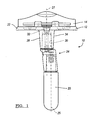
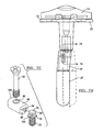
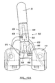
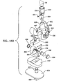
- FIG 1 is an anterior view illustration of a knee joint prosthesis including a modular tibial component having a first adapter assembly for providing a first predetermined offset according to the present teachings;
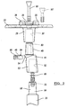
- FIG. 2 is an exploded view of the modular tibial component of FIG. 1 ;
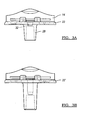
- FIG. 3A is an anterior view of the tibial component of FIG. 1 ;
- FIG. 3B is an anterior view of a tibial component according to additional features
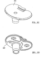
- FIG. 3C is a perspective view of a tibial component according to additional features
- FIG. 3D is a perspective view of a tibial component according to additional features
- FIG. 4 is a view of a first adapter body according to the present teachings.
- FIG. 5 is a view of another adapter body according to additional features
- FIG. 6 is a view of an exemplary stem and fastener insert
- FIG. 7A is a cross-sectional view taken along a superior/inferior line through the adapter of FIG. 1 ;
- FIG. 7B is a view of the knee joint prosthesis of FIG. 1 illustrating various offsets
- FIG. 7C is an exploded view of a locking assembly shown in FIG. 7A ;
- FIG. 8 is an anterior view of an exemplary femoral component according to the present teachings and shown with the adapter assembly of FIG. 1 ;
- FIG. 9 is a perspective view of a tibial tray and bearing according to additional features.
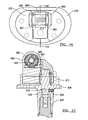
- FIG. 10 is a perspective view of the tibial tray of FIG. 9 ;
- FIG. 11 is a perspective view of an inferior surface of the bearing of FIG. 9 ;
- FIG. 12 is a perspective view of a superior surface of the bearing of FIG. 9 ;
- FIG. 13 is a top view of the tibial tray and bearing of FIG. 9 ;
- FIG. 14 is a cross-sectional view taken along the line 14-14 of FIG. 13 ;
- FIG. 15 is a perspective view of a hinged knee joint prosthesis according to additional features.
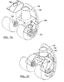
- FIG. 16A is a cross-sectional view taken along the line 16-16 of FIG. 15 and shown with the femoral component rotated;
- FIG. 16B is a cross-sectional view of a hinged knee prosthesis according to additional features
- FIGS. 17-20 show an exemplary sequence of assembling the knee joint prosthesis of FIG. 15 ;
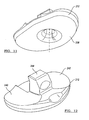
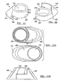
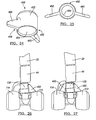
- FIG. 21 is a perspective view of a first augment according to the present teachings.
- FIG. 22 is a perspective view of a second augment according to the present teachings.
- FIG. 23A is a plan view of the first and second augments of FIGS. 21 and 22 ;
- FIG. 23B is side view of the first and second augments in an mated or interlocked position
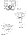
- FIG. 24 is a perspective view of a third augment according to the present teachings.
- FIG. 25 is a top view of the third augment of FIG. 24 ;
- FIG. 26 is an anterior view of the femoral component of FIG. 8 shown with the first augment assembled on a superiorly extending portion;
- FIG. 27 is an anterior view of the femoral component of FIG. 8 shown with the first and second augments assembled on a superiorly extending portion;
- FIG. 28 is a superior view of the femoral component of FIG. 27 and shown with the augment of FIG. 24 secured to an inferiorly extending portion;
- FIG. 29 is an anterior view of the tibial component of FIG. 1 shown with the first and second augments assembled on an inferiorly extending portion and without the adapter assembly;
- FIG. 30 is an anterior view of the tibial component of FIG. 1 shown with the third augment assembled on the inferiorly extending portion;
- FIG. 31 is an exploded view of a modular tibial component according to additional features
- FIG. 32 is a perspective view of an augment according to additional features
- FIG. 33 is a perspective view of another augment according to the present teachings.
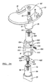
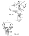
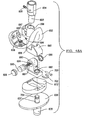
- FIG. 34 is an exploded perspective view of an adapter assembly according to additional features and shown with an exemplary tibial component and stem;
- FIG. 35 is an anterior view of the prosthesis illustrated in FIG. 34 ;
- FIG. 36A is a detail exploded view of the tibial tray and adapter illustrated in FIG. 34 ;
- FIG. 36B is a partial sectional view taken along line 36B-36B of FIG. 36A ;
- FIG. 36C is a detail exploded view of an adapter assembly cooperating with a tibial component according to additional features
- FIG. 36D is a partial sectional view taken along line 36D-36D of FIG. 36C ;
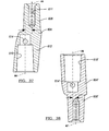
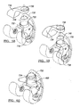
- FIG. 37 is a sectional view of an exemplary adapter having a first offset
- FIG. 38 is a sectional view of another exemplary adapter having a second offset
- FIG. 39A is an exploded view of a fastener member and insert of the adapter assembly
- FIG. 39B is a partial exploded view of an adapter assembly
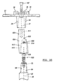
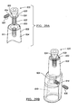
- FIG. 40A is an assembled view of a tibial component, adapter assembly and stem according to one example of the present teachings
- FIG. 40B is a sectional view taken along line 40B-40B of FIG. 40A ;
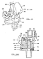
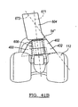
- FIG. 41A is an assembled view of an exemplary femoral component, adapter assembly and stem according to one example of the present teachings
- FIG. 41B is an assembled posterior perspective view of a pair of interlocking augments, adapter assembly and femoral component according to one example of the present teachings;
- FIGS. 42-45 are perspective views of various tibial components and bearings used in cooperation with a bone conserving hinged knee;
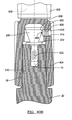
- FIG. 46 is a superior view of an assembled hinged knee
- FIG. 47 is a sectional view taken along line 47-47 of FIG. 46 ;
- FIGS. 48A and 48B are exploded perspective views of a hinged knee prosthesis according to one example of the present teachings.
- FIG. 49 is a sectional view of the hinged knee prosthesis of FIGS. 48A and 48B shown assembled
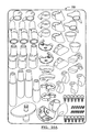
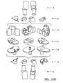
- FIGS. 50-54 are perspective views of various augments according to the present teachings.
- FIG. 55A and 55B illustrates a kit of implants according to the present teachings.
- FIGS. 56-60 illustrate various augments shown during stages of assembly.
- the instant disclosure provides a knee joint prosthesis system having various knee joint prostheses that may be adapted for use in a revision knee procedure.
- Various tibial and femoral components are described that may be used alone or as part of a crutiate retaining (CR) knee revision, posterior stabilized (PS) knee revision, fully constrained knee revision and hinged knee revision.
- the instant disclosure further provides various modular adapters, stems and augments that may be used in any combination with any of the tibial and femoral components disclosed herein.
- all of the components disclosed that are above and below the joint line can be inter-changeably used with any of the knee prostheses disclosed herein and on the tibial or femoral side.
- selection of any of the knee prostheses and related components from the knee joint prosthesis system may be selected intra-operatively by the surgeon performing the procedure.
- a knee joint prosthesis constructed in accordance with the present teachings is illustrated and generally identified at reference number 10.
- the knee joint prosthesis 10 is generally shown to include a tibial component 12 that supports a bearing 14 which engages an articulation surface of a femoral component (not shown).
- a first crutiate retaining (CR) bearing 14 is illustrated that is designed to articulate with a CR femoral component.
- a fixed PS bearing may be employed that is designed to articulate with a PS femoral component.
- the tibial component 12 illustrated in FIG. 1 will be understood to be modular in construction and generally include a stem 20, a tray 22, and a first adapter assembly 24.
- the adapter assembly 24 can connect the tray 22 and the stem 20 so as to provide an offset to the stem 20 in the transverse or coronal plane or in any other plane.
- a central axis 25 of the stem 20 can be offset from a central axis 27 of an inferiorly extending portion 28 of the tray 22.
- the first adapter assembly 24 can provide a first offset of approximately 5 mm.
- the offset can range from 0 mm to approximately 5 mm or more and can be in any rotational direction relative to the central axis 27.
- a stem 20 can be attached directly to the tray 22 ( FIG. 29 ).
- the offset axis 25 can be rotated 360 degrees relative to the central axis 27 to provide the surgeon with various intra-operative options to select depending on the patient's needs.
- the adapter assembly 24 or stem 20 can be rotational keyed to provide only a limited range of adjustment, such as providing only a single offset or two offset positions.
- the inferiorly extending portion 28 of the tibial tray 22 can define a female tapered receiving portion 30.
- the female tapered receiving portion 30 can taper slightly as it extends into the inferiorly extending portion 28.
- a central aperture 32 can be formed through the tray 22 and the inferiorly extending portion 28 into the female tapered receiving portion 30.
- the inferiorly extending portion 28 may also define an exterior tapered augment receiving surface 34.
- a retaining rail 36 ( FIG. 2 ) can extend superiorly from a posterior edge of the tray 22.
- the tibial tray 22 can further include a pair of posts 38 integrally formed on a superior surface at an anterior edge thereof. The posts 38 and rail 36 can cooperate to retain the modular bearing 14 in a fixed position on the tray 22.
- An alternate tibial tray 22' is shown in FIG. 3B .
- the modular bearing 14 can be formed of ultra-high molecular weight polyethylene (UHMWPE) with anterior and posterior recesses (not specifically shown) to receive the posts 38 and rail 36, respectively, and with a uniformly flat inferior surface on its intercondylar and medial/lateral portions for direct contact with the superior surface of the tray 22.
- UHMWPE ultra-high molecular weight polyethylene
- the modular bearing 14 can be designed to be locked in position with a transverse slide-in locking bar or clip 40 wedged between the posts 38 and the bearing 14 in opposed grooves provided therein for that purpose.
- a more detailed discussion of how the locking bar cooperates with the posts and bearing may be found in commonly owned U.S. Pat. No. 5,330,534 entitled "Knee Joint Prosthesis With Interchangeable Components".
- Modular tibial trays and bearings as generally described above are commercially available from Biomet Inc., the assignee of the present disclosure, as components of the Vanguard ® Complete Knee System, which includes various sizes and configurations of trays, bearings and other knee components for different patient requirements.
- the articulating surfaces of the modular bearing 14 can be substantially the same as provided by the Vanguard ® Complete Knee System.
- the adapter assembly 24 can generally include an adapter body 44 and a locking member or element 46 ( FIG. 2 ).
- the adapter body 44 of the adapter assembly 24 can define a male tapered insertion portion 48 having a passage 50 formed therethrough.
- a female tapered receiving portion 52 can be formed in an offset body portion 53 of the adapter body 44 for receiving a male tapered insertion portion 58 of the stem 20.
- the female tapered receiving portion 52 can be generally cylindrical.
- a skirt 54 can be defined at a transition between the male tapered insertion portion 48 and the offset body portion 53.
- the male tapered insertion portion 48 of the adapter body 44 defines a first axis A 1 and the female tapered receiving portion 52 defines a second axis A 2 .
- the first axis A 1 and the second axis A 2 are parallel to one another and spaced apart to provide the desired offset.
- multiple adaptors each having a different offset can be provided to provide the surgeon with intra-operative selection depending on the patient's needs.
- the adapter body 44 provides a 5mm offset
- the first and second central axes A 1 and A 2 are spaced apart 5mm.
- the adapter body 44' can define a skirt 54' having an alternate configuration. Other geometries are contemplated for the skirt 54, 54'.
- the male tapered insertion portion 48 can taper slightly as it extends away from the adapter body 44.
- the female tapered receiving portion 52 similarly tapers slightly as it extends into the adapter body 44 from an end of the adapter body 44.
- various male tapered insertion portions (such as portion 48) can be inserted in various female tapered receiving portions (such as portion 52) to form a locking taper or Morse taper.
- the adapter body 44 is illustrated to further define a laterally extending channel 60 which intersects both the aperture 50 and the female tapered receiving portion 52.
- the locking element 46 can extend into the laterally extending channel 60 where it ultimately couples the tray 22 to the stem 20.
- the stem 20 can include an upper portion 64 that cooperatively engages with the locking element 46.
- the upper portion 64 of the stem 20 can include a fastener insert 66.
- the fastener insert 66 of the stem 20 may be integrally formed to cooperate with the locking element 46.
- the fastener insert 66 can include a distal portion 70 which can be externally threaded for engaging an internally threaded aperture 72 of the male tapered insertion portion 58 of the stem 20.
- the fastener insert 66 can further include a central portion 74 having a hexagonal or other suitable cross-section which can be engaged by a tool (not shown) for rotating the fastener insert 66 into the stem 20.
- the fastener insert 66 can include a proximal end 78 including an enlarged diameter head 80.
- the locking element 46 can be sized and configured to be inserted through an opening 81 in the sidewall of the adapter body 44 and into the channel 60 for coupling of the stem 20 and the tray 22.
- the locking element 46 can include an upper surface 84 (see FIG. 2 ) having an internally threaded aperture 86.
- the internally threaded aperture 86 can threadably receive a fastener 90 which can extend through the central aperture 32 provided in the tray 22.
- the fastener 90 can align with the central longitudinal axis 27 of the inferior portion 28 of the tray 22.
- the locking element 46 can additionally include an open end 94 and a bottom surface having a slot 96.
- the slot 96 can intersect the open end 94.
- the open end 94 can receive the head 80 of the stem insert 66 as the locking element 46 is inserted through the opening 60.
- the slot 96 can accommodate a reduced diameter, central portion 100 of the fastener insert 66.
- the head 80 of the fastener insert 66 can have a diameter greater than a width of the slot 94 for coupling of the fastener insert 66 with the locking element 46.
- the locking element 46 can further include a closed end 104.
- the closed end 104 can be convexly curved. When the locking element 46 is completely inserted into the channel 60, the closed end 104 can be flush with the sidewall of the adapter body 44.
- the fastener insert 66 can be screwed into the stem 20.
- the adapter body 44 can be placed over the male insertion portion 64 of the stem 20 such that the male insertion portion 64 is received in a press fit within the female tapered receiving portion 52 of the adapter body 44 and the upper end 78 of the fastener insert 66 extends into the laterally extending channel 60.
- the male taper extension 48 of the adapter 44 can now be press fit onto the female tapered receiving portion 30 of the tray 12 with the adapter body 44 oriented to provide the offset in the desired direction.
- the adapter body 44 may be rotated about the axis A 1 prior to fastening to orient the stem 20 at the desired offset for a particular patient.
- the stem 20 may extend at a plurality of positions around a radius defined by the axes A 1 and A 2 .
- the stem 20 may be keyed with the adapted body thus, precluding rotation.
- a set of stems may be provided having various lengths suitable for a range of patients.
- a set of adapter bodies may be provided for providing various offsets.
- the locking element 46 can be inserted into the laterally extending channel 60 through the opening 81. Upon complete insertion, the locking element 46 can engage the fastener insert 66.
- the tray 22 can be secured to the adapter body 44 by the threaded fastener 90 which extends through the central aperture 32 of the tray 22 and threadably engages the internally threaded aperture 86 of the locking element 46.
- the tibial tray defines an inferiorly extending male portion whereas in the instant application, the tibial tray 22 defines the inferiorly extending the female receiving portion 30.
- the adapter body 44 may alternatively define an axis A 2 that defines an angle with respect to the axis A 1 .
- the male insertion portion 58 may be inserted directly into the female receiving portion 30 of the tray 22.
- another threaded fastener 90' may be used that has a shorter shaft for spanning an appropriate distance to mate directly with the threaded aperture 72 of the stem 20.
- FIGS. 3A-3D other tibial trays 22A, 22B, 22C and 22D, are shown for accommodating various combinations of fasteners 90, 90', adapters 44, 44' and stems 20.
- the knee joint prosthesis 110 includes a femoral component 112.
- the femoral component 112 may be used as part of a posterior stabilized (PS) knee joint prosthesis.
- PS knee joint prosthesis can provide adequate stability in case of moderate deterioration or instability of a knee. This most typically occurs when the anterior and posterior cruciate ligaments are sacrificed or dysfunctional and the medial and lateral collateral ligaments remain functionally intact.
- the femoral component 112 can include a first condylar portion 114 and a second condylar portion 116 that provide a first femoral bearing surface 118 and a second femoral bearing surface 120, respectively.
- the first and second condylar portions 114 and 116 of the femoral component 112 can be interconnected by an inner condylar portion 122 that defines an intercondylar recess 124.
- a superiorly extending portion 130 may be formed on the femoral component 112.
- the superiorly extending portion 130 can include a generally tapered outer body to receive the augments described herein and define a female tapered receiving portion 132.
- the female tapered receiving portion 132 of the femoral component 112 may be configured to accept one of the adapter bodies 44, 44' described above.
- the male tapered insertion portion 48 of the adapter body 44 can be adapted to be inserted and press-fit into the female tapered receiving portion 132 of the femoral component 112.
- the first axis A 1 and the second axis A 2 are parallel to one another and spaced apart.
- the exemplary adapter assembly 24 has been described as having a 5 mm offset however, other adapter bodies may be provided having various offsets.
- a locking element 46 and stem 20 may be used according to the description above.
- the knee joint prosthesis 210 is generally shown to include a tibial component 212 that supports a rotating constrained bearing 214.
- the tibial component 212 can generally include a substantially planar platform-like tibial tray 216 ( FIG. 10 ) and an inferiorly extending portion 218.
- the inferiorly extending portion 218 can define a tapered female receiving portion 220 and an outer tapered body for receiving augments disclosed herein.
- the tibial tray 216 can further include a superiorly extending post 224.
- a transition between the tibial tray 216 and the superiorly extending post 224 can be defined by a varying radius R, or more specifically transition between a radius R 1 having a radius of approximately 0.50 inches, and a radius R 3 having a radius of approximately 1.50 inches.
- An intermediate radius R 2 can have a radius of approximately 0.38 inches. It is appreciated that the radius R may define other dimensions.
- the transition of the varying radius R can minimize stresses experienced on the superiorly extending post 224.
- An axis A 3 ( FIG. 14 ) defined trough the post 224 can be laterally offset in the posterior direction relative to an axis A 4 defined through the inferiorly extending portion 218.
- a threaded aperture 228 can be formed through the anterior portion of the tibial tray 216. The threaded aperture 228 can extend generally perpendicular to the axis A 4 .
- the inferiorly extending portion 218 can define a tapered augment receiving surface 230.
- the tibial tray 216 can be formed from cobalt-chromium-molybdenum or any other suitable biocompatible material.
- a top 232 ( FIG. 10 ) of the tibial tray 216 can be highly polished to provide a substantially smooth tibial bearing surface 234.
- the rotating bearing 214 can have a substantially planar inferior bearing surface 238 ( FIG. 11 ) which can rotatably move relative to the highly polished tibial bearing surface 234.
- the rotating bearing 212 can further include a first superior articulating or bearing surface 240 and a second superior articulating or bearing surface 242.
- the bearing surfaces 240 and 242 can be formed anteriorly and laterally from a central superiorly extending portion 244.
- the first bearing surface 240 and the second bearing surface 242 can articulate with respective bearing surfaces of a first and second condyle of a constrained femoral component (not shown).
- the rotating bearing 212 can be formed from a surgical grade, low friction, low wearing plastic, such as UHMWPE or other suitable material.
- a posterior edge 246 of the tibial tray 216 can define a surface that defines an angle 247 relative to a posterior edge 250 of the bearing 214.
- the angle 247 can be approximately 8 degrees. Other angles are contemplated.
- the stem 20 can include a fastener insert 66'.
- the fastener insert 66' can include a distal portion 70' which is externally threaded for engaging an internally threaded aperture 72 of the male tapered insertion portion 64 of the stem 20.
- the fastener insert 66' can further include a central portion 74' having a hexagonal or other suitable cross-section which can be engaged by a tool (not shown) for rotating the fastener insert 66' into the stem 20.
- the fastener insert 66' can include an upper end 78' including a conical engaging head 80'.
- a set screw 252 can be advanced through the threaded aperture 228 of the tibial tray 216 to engage the conical engaging head 80'. In this way, advancement of the set screw 252 can secure the fastener insert 66', and therefore, the stem 20 in a secure position. It is appreciated that when utilizing the adapter body 44, a fastener such as fastener insert 66' but having a longer shank, may alternately be used for threadably securing to the locking element 46.
- the knee joint prosthesis 310 is generally shown to include a tibial component 312 that supports a bearing 314 which engages an articulation surface of a femoral component 316.
- the tibial component 312 can generally include a substantially planar platform-like tibial tray 318 and an inferiorly extending portion 320.
- the inferiorly extending portion 320 can define a tapered female receiving portion 322.
- the tibial tray 318 can further include a superiorly extending post 324.
- a cap 326 can be securably inserted into an elongate bore 328 defined at a terminal opening of the superiorly extending post 324.
- a threaded aperture 330 can be formed through the tibial tray 318.
- the threaded aperture 330 can extend generally perpendicular to an axis defined by the superiorly extending post 324.
- the tibial tray 318 can be formed from cobalt-chromium-molybdenum or any other suitable biocompatible material.
- a set screw (not shown) can be advanced through the threaded aperture 330 of the tibial tray 318 to engage a conical engaging head of a fastener insert (as described in detail above regarding FIG. 14 ). In this way, advancement of the set screw can secure the fastener insert, and therefore the adapter body 44 or the stem 20 in a secure position.
- the top of the tibial tray 318 can be highly polished to provide a substantially smooth tibial bearing surface 331.
- the rotating bearing 314 can have a substantially planar inferior bearing surface 332 which can rotatably move relative to the highly polished tibial bearing surface 331.
- the rotating bearing 314 can further include a first superior articulating or bearing surface 336 and a second superior articulating or bearing surface 338.
- the first bearing surface 336 and the second bearing surface 338 can articulate with respective bearing surfaces of a first and second condyle 340 and 342, respectively of the femoral component 316.
- the bearing surfaces may be similar to those provided in the Vanguard ® Complete Knee System.
- the bearing 314 can include a stabilizing post 350 which can project superiorly from the bearing surface.
- the stabilizing post 350 can include a fin-like body 352 having a raised posterior portion 354 and a lower anterior portion 356.
- the body 350 can define a first and second laterally spaced-apart sides 360 and 362 ( FIG. 17 ).
- the first and second sides 360 and 362 of the stabilizing post 350 can be positioned so as to extend into an intercondylar recess 366 ( FIG. 15 ) of the femoral component 316.
- a stabilizing post aperture 370 can be formed in a superior/inferior direction through the body 350.
- a passage 372 can be formed through the raised posterior portion 354 of the body 350.
- the passage 372 can extend generally through the first and second sides 360 and 362 of the stabilizing post 350 in a direction generally perpendicular to the stabilizing post aperture 370.
- the rotating bearing 314 can be formed from a surgical grade, low friction, low wearing plastic, such as UHMWPE or other suitable material.
- FIG. 16B An alternate stabilizing post 350' is shown in FIG. 16B that accepts a cap or fastener 326'.
- the first and second condylar portions 340 and 342 of the femoral component 316 can be interconnected by an inner condylar portion 380 that defines the intercondylar recess 366.
- the intercondylar portion 380 can include a first lateral sidewall 382 and a second lateral sidewall 384 ( FIG. 17 ) which can be planar and substantially parallel to each other.
- the first and second lateral sidewalls 382 and 384 can further define hinge passages 388 formed respectively therethrough.
- Anterior portions of the first and second lateral sidewalls 382 and 384 can be connected by an anterior surface 390 ( FIG. 15 ) of the intercondylar portion 380.
- the anterior surface 390 of the intercondylar portion 380 can angle anteriorly in an inferior direction at approximately 60 degrees with respect to a superior surface of the intercondylar portion 380.
- a superiorly extending portion 392 may be formed on the femoral component 316 and generally extend from a superior surface 394 ( FIG. 16A ).
- the superiorly extending portion 392 can include a generally cylindrical body and define a female tapered receiving portion 394.
- a hinge post 396 can securably extend through the respective hinge passages 388 of the first and second lateral sidewalls 382 and 384 of the femoral component 316 and through the passage 372 in the bearing 314.
- the lateral sidewalls 382 and 384 of the femoral component 316 can be positioned proximate an inboard portion of the respective first and second condyles 340 and 342. In this way, host bone need not be sacrificed in areas outboard to the lateral sidewalls 382 and 384.
- the femoral component 316 can rotate about the hinge pin 396.
- FIG. 17 illustrates an exploded view of the respective femoral component 310, hinge pin 396 and bearing 314.
- the femoral component 310 is placed onto the bearing 314 such that the respective passages 372 and 388 are aligned.
- FIGS. 19-20 show the hinge pin 296 inserted into the passages 372 and 388.
- FIGS. 21-23B illustrate a first pair of augments 400 and 402.
- the first augment 400 can generally define a body 404 having first end 406 and a second end 408.
- the body 404 can further define a consistent radius portion 410 at the second end and 408 an outwardly tapered radially extending portion 412 near the first end 406.
- the consistent radius portion 410 can define a tapered receiving bore 416 formed therethrough.
- the receiving bore 416 can taper from the first end 406 to the second end 408.
- a first step 420 may be formed in the body 404 between the consistent radius and the radially extending portions 410 and 412, respectively.
- a collection of first augments may be provided having various dimensions and configurations suitable for a particular patient.
- the second augment 402 can generally define a body 424 having first end 426 and a second end 428.
- the body 424 can further define a consistent radius portion 430 at the first end 426 and an outwardly tapered radially extending portion 432 near the second end 428.
- the consistent radius portion 430 can define a tapered receiving bore 436 formed therethrough.
- the receiving bore 436 can taper from the first end 426 to the second end 428.
- a second step 440 may be formed at the second end 428 between the consistent radius and the radially extending portions 430 and 432, respectively.
- a collection of first augments may be provided having various dimensions and configurations suitable for a particular patient.
- the first and second augments 400 and 402 may be used singly or as a combination. As shown in FIG. 23B , the first and second augments 400 and 402 can interlock or mate at the first and second steps 420 and 440 when used concurrently with any of the tibial and femoral components described above.
- the third augment 450 can generally define a body 452 having a first end 454 and a second end 456.
- the body 452 can further define a pair of wing portions 460 extending radially therefrom to provide rotational stability to either the femoral component or the tibial component.
- the wing portions 460 may be offset toward the first end 454.
- the body 452 can define a tapered receiving bore 464 formed therethrough. The receiving bore 464 can taper from the second end 456 to the first end 454.
- the receiving bores 416, 436 and 464 of each of the augments 400, 402 and 450 can be slidably press-fit onto any of the inferior extensions of the tibial trays described above. More specifically, the receiving bores can define a tapered interlock with the tapered augment receiving surfaces of the inferior extensions of the tibial trays. Likewise, any of the same augments can also be slidably press-fit onto any of the superior extensions of the femoral components described above. More specifically, the receiving bores can define a tapered interlock with the tapered augment receiving surfaces of the superior extensions of the femoral components. As such, the respective tapered surfaces can cooperate to form a Morse taper.
- a second augment 402 is shown secured to the superior extension 130 of the femoral component 112 ( FIG. 26 ). If a surgeon desires to account for additional bone loss, the first augment 400 may also be advanced onto the superior extension 130 of the femoral component 112 ( FIGS. 27 and 29 ). As shown, the respective first and second steps 420 and 440 cooperate to mate or form an interlock.
- FIG. 29 a first and second augment 400 and 402 are shown secured to the inferior extension 28 of the tibial tray 22.
- the first and second augments 400 and 402 may be used with or without the adapter. It is appreciated, that any of the augments may be used with or without the adapter assemblies described above.
- FIG. 30 illustrates the third augment 450 secured to the inferior extension 28 of the tibial tray 22.
- the tibial component 522 can define one or more (such as a pair) of blind bores 524 and at least one opening 526 formed on an inferior surface.
- a recessed portion such as pocket 530 may also be optionally formed on an inferior surface of the tibial component 522.
- An augment 540 can define one or more (such as a pair) of complementary locating pegs 542 and at least one complementary opening 544.
- the augment 540 can be adapted to secure onto the inferior surface of the tibial component 522 to compensate for bone loss.
- an augment may be provided on one of a lateral or medial portion, or both, of the tibial component 522.
- the locating peg 542 may nest within a blind bore 524.
- a fastener (not shown) may be inserted through the respective openings 526 and 544.
- Another augment 540' having at least one peg 542' can be provided for the opposite of the medial and lateral sides of the inferior surface of the tibial component 522.
- an augment 540" suitable for connecting to either of the medial and lateral sides is provided.
- pegs (such as pegs 542, FIG. 31 ) need not be provided.
- a plurality of augments 540 can be provided having various thicknesses such that a surgeon can assemble a particular augment suitable for a given patient.
- a stem 20 can be fixedly accepted into a female tapered extending portion 560 of the tray.
- FIG. 33 illustrates another augment 590 that defines a tapered receiving bore 592 formed therethrough.
- the tapered receiving bore 592 can be slidably press-fit onto any of the inferior extensions of the tibial trays and/or the superior extensions of the femoral components described above.
- a portion of the augment 590 can optionally be formed of porous metal 594.
- the porous metal 594 can comprise porous titanium alloy for example.
- the augment 590 can define an inner solid metal sleeve portion and an outer porous metal sleeve portion 594.
- the respective femoral components, tibial components, bearings and/or augments may be part of a kit wherein a surgeon may intra-operatively select a desired component or components needed for a particular patient.
- the modular tibial component 22 (as described above with respect to FIGS. 1-3A ) is shown cooperating with an adapter assembly 600 according to additional features.
- the adapter assembly 600 can cooperate with the stem 20.
- the adapter assembly 600 can connect the tray 22 and the stem 20 so as to provide an offset to the stem 20 in the transverse or coronal plane or in any other plane.
- the central axis 25 of the stem 20 can be offset from the central axis 27 of the inferiorly extending portion 28 of the tray 22.
- the adapter assembly 600 can provide a first offset of approximately 5mm.
- the offset can range from 0mm to approximately 5mm or more and can be in any rotational direction relative to the central axis 27.
- the offset axis 25 can be rotated 360 degrees relative to the central axis 27 to provide the surgeon with various intra-operative options to select depending on the patient's needs.
- the adapter assembly 600 or stem 20 can be rotational keyed to provide only a limited range of adjustment, such as providing only a single offset or two offset positions.
- the adapter assembly 600 can generally include an adapter body 604 and a locking member or element 606.
- the adapter body 604 of the adapter assembly 600 can define a male tapered insertion portion 608 and a female tapered receiving portion 610.
- the male tapered insertion portion 608 can define a threaded bore 611.
- the female tapered receiving portion 610 can be formed in an offset body portion 612 of the adapter body 604 for receiving a male tapered insertion portion 58 of the stem 20.
- the adapter body 604 can define flats 614 on an outer surface for gripping and facilitating alignment as will be described.
- a skirt (not shown), similar to the skirt 54 formed on the adapter body 44 illustrated in FIG. 2 , can be defined at a transition between the male tapered insertion portion 608 and the offset body portion 612.
- a non-skirted transition can alternatively be formed as shown herein.
- a bore 614 can be defined from an outer surface of the adapter body 604 to the female tapered receiving portion 610. The bore 614 can define threads 616 that threadably receive the locking member 606.
- the male tapered insertion portion 608 of the adapter body 604 defines a first axis A 5 and the female tapered receiving portion 610 defines a second axis A 6 .
- the first axis A 5 and the second axis A 6 are parallel to one another and spaced apart to provide the desired offset.
- multiple adaptors each having a different offset can be provided to provide the surgeon with intra-operative selection depending on the patient's needs.
- the adapter body 604 provides a 5mm offset
- the first and second central axes A 5 and A 6 are spaced apart 5mm.
- the adapter body 604 can define axes having an alternate offset.
- an adapter body 604' ( FIG. 38 ) includes a male tapered insertion portion 608' that defines a first axis A 7 and the female tapered receiving portion 610' that defines a second axis A 8 .
- the adapter body 604' can define an offset of 2.5mm.
- the male tapered insertion portion 608 can taper slightly as it extends away from the adapter body 604.
- the female tapered receiving portion 610 similarly tapers slightly as it extends into the adapter body 604 from an end of the adapter body 604.
- various male tapered insertion portions (such as portion 608) can be inserted in various female tapered receiving portions (such as portion 610) to form a locking taper or Morse taper.
- the locking member 606 can extend into the bore 614 where it ultimately engages a fastener insert 620.
- the fastener insert 620 can include a distal portion 622 which can be externally threaded for engaging the internally threaded aperture 72 of the male tapered insertion portion 58 of the stem 20.
- the fastener insert 620 can further include a central portion 624 and a proximal portion 626.
- the proximal portion 626 can define a conical engaging head 630.
- a gripping detail 632 (such as, but not limited to, a hex-bore for receiving an Allen wrench), can be formed in an upper surface of the proximal portion 626.
- the fastener insert 620 or more specifically the conical engaging head 630 can be formed of a first biocompatible material while the locking member 606 can be formed of a second biocompatible material.
- the second biocompatible material can be a higher durometer (harder) material than the first biocompatible material.
- the tibial tray 636 can be part of a bone-conserving hinge knee prosthesis ( FIG. 48A ).
- the tibial tray 636 can define a superiorly extending stub 637 and an inferiorly extending portion 638 that defines a female tapered receiving portion 640.
- the inferiorly extending portion 638 can define an exterior tapered augment receiving surface 642.
- the tibial tray 636 can define a threaded passage 646 formed through the tray portion of the tibial tray 636.
- the treaded passage 646 can be adapted to threadably accept the locking member 606.
- the tibial tray 636 can provide the threaded passage 646 for receiving the locking member 606 in the anterior/posterior direction.
- the fastener insert 620 can be threaded into the threaded bore 611.
- the fastener insert 620 can be threaded until the central portion 624 engages a terminal surface 650 of the male tapered insertion portion 608 of the adapter body 604.
- the stem 20 can be coupled to the adapter body or the adapter body 604 can be coupled to the tibial tray 636.
- the adapter body 604 can be coupled to the tibial tray 636, by inserting the male tapered insertion portion 608 of the adapter body 604 into the female tapered receiving portion 640 of the tibial tray 636. The surgeon can then rotate the male tapered insertion portion 608 within the female tapered receiving portion 640 to attain the desired orientation.
- the instant disclosure provides various tools for verifying a correct orientation of the adapter body 604 prior to securing the adapter body 604 in a fixed position relative to the tibial tray 636. Once the desired orientation has been attained, the locking member 606 can be threaded from an unsecured position ( FIG. 36C ) into engagement with the conical engaging head 630 to a secured position ( FIG. 36D ).
- the locking member 606 can be formed of a biocompatible material that is harder than the fastener insert 620.
- a distal end 654 of the locking member 606 can deform (e.g. create a depression at) an interface area of the conical engaging head 630.
- the deformed area is identified at reference numeral 656 ( FIGS. 39A and 40B ).
- the locking function of the locking member 606 can be improved by providing a greater resistance to separation.
- the resultant depression can inhibit sliding, rotation, or other relative movement between the locking member 606 and the fastener insert 620.
- the stem 20 can be coupled to the adapter body 604 by driving the locking member 606 (i.e. another identical locking member 606) into the fastener insert 620 (i.e. another identical fastener insert 620).
- the threads 616 defined by the bore 614 can define a thread profile that is slightly different (i.e. pitch) than threads 662 defined by the locking member 606.
- one of the threads 616 or 662 can be deformed initially.
- Such a relationship can allow the locking member 606 to be retained within the bore 614 upon initial handling by a surgeon.
- the locking member 606 can already by positioned within the bore such that the surgeon would not need to locate the distal tip 654 of the locking member 606 into the bore 616 (i.e. mate two separate components). It is appreciated that such thread configuration would not preclude rotation of the locking member 606 within the bore 616 during fastening.
- the adapter assembly 600 including the adapter body 604 and the locking member 606 are shown assembled with a femoral component 112'.
- the femoral component 112' is substantially similar to the femoral component 112 ( FIG. 8 ), but can define a threaded bore 668 formed in a femoral box 670.
- the threaded bore 668 can provide a similar function to the threads 616 of the bore 614 of the adapter body 604.
- a locking member 606 can be driven to engage a conical engaging head 630 of fastener insert 620.
- a skirt 54" is shown on the adapter body 604.
- the skirt 54" generally defines a flared contour portion that can provide a generally smooth geometrical transition onto the outwardly tapered radially extending portion 432 (see also FIG. 21 ) of the augment 402.
- the geometrical transition between the skirt 54" and the augment 402 can reduce otherwise sharp transitions between implanted components to provide a favorable nesting configuration with surrounding bone in an implanted position.
- the male tapered insertion portion 608 of the adapter 604 can define an attachment axis 671.
- the outwardly tapered radially extending portion 432 of the body 424 can define a plane 673.
- the flared contour portion of the skirt 54" can taper generally along the plane 673 in an implanted position. The skirt 54" can therefore cooperate with the augment 402 to effectively fill bone voids.
- an adapter assembly 600 can be used on either side of the joint line (e.g. with a tibial component, such as described in relation to FIG. 35 , and also a femoral component, such as described in relation to FIG. 41 ).
- the locking member 606 and fastener insert 620 combination can be used in several distinct areas as described above.
- the augments such as disclosed in FIGS. 21-25 can be used in cooperation with either a superiorly extending portion (such as portion 130, FIG. 8 ) of a femoral component or an inferiorly extending portion (such as portion 638, FIG. 36C ) of a tibial component.
- the tibial tray 636 can be used as part of a bone-conserving hinge knee prosthesis.
- the tibial tray 636 can cooperate with a bearing 672.
- a keel 680 can define a first bore 682 for receiving the superiorly extending stub 637, and a second bore 684 for receiving an axle 686.
- a pair of hubs 688 can engage opposite ends of the axle 686.
- a biasing member 687 can bias against an outer surface on the keel 680 to bias the axle 686 outward.
- the keel 680 can be intraoperatively coupled to the femoral component 692 by depressing the axle 686 in a direction inwardly and locating the keel 680 generally into the femoral box 696 of the femoral component 692 until the axle 686 aligns with passages 695 and 697 formed in the femoral box.
- the hubs 688 can nest in the passages 695 and 697 on opposite ends of the axle 686.
- the axle 686 can bias outwardly encouraging the hubs 688 to seat into the passages 695 and 697.
- the hubs 688 can provide a rotational surface for supporting the axle 686.
- the hubs 688 can be formed of any suitable bearing material such as PEEK, polyethylene, carbon reinforced PEEK.
- a pin 700 can then be inserted into the keel 680 to inhibit inward compression of the axle 686.
- a shoe 690 can be disposed intermediate of the keel 680 and a femoral component 692.
- the femoral component 692 can define a threaded bore 694 through the box 696.
- a superiorly extending portion 698 can receive a male tapered insertion portion 608 of the adapter body 604.
- the locking member 606 can be used as described above to engage a fastener insert 620 (not specifically shown) extending proud from the male insertion portion 608.
- a fastener can extend superiorly though the femoral component 692 to securably mate with the adapter body 604 (such as shown in FIG. 8 ).
- a horseshoe clip 702 can securably nest in an annular pocket 704 defined on the stub 637.
- An augment 710 can define a substantially symmetric profile for securing to either a medial or lateral inferior side of a tibial tray (i.e. such as tibial tray 22D, FIG. 3D ).
- Passages 712 can be formed through the augment 710 for receiving a fastener (not shown) in an assembled position.
- Augments 716 and 718 can define passages 720 and 722, respectively for receiving a superiorly extending portion 724 of a femoral component 730 (see FIG. 58 ).
- the augments 716 and 718 can define a profile unique for cooperating with a medial or lateral side of a femoral box 732.
- the augment 716 can be implanted to occupy an area of bone loss on a medial side of the femoral component 730.
- the augment 718 can be implanted to occupy an area of bone loss on a lateral side of the femoral component.
- Augments 734 and 736 can define passages 738 and 740 respectively ( FIG. 59 ).
- the augments 734 and 736 can be used individually or in combination.
- the respective passages 720, 722, 738 and 740 and the superiorly extending portion 724 of the femoral component 730 can define conical engaging surfaces that are adapted to provide a friction fit formed by a Morse-type taper.
- the augments 734 and 736 can define a profile different than the augments 716 and 718.
- the augment 744 can define a passage 746.
- the augment 744 can be symmetric for coupling to either a medial or lateral surface of the femoral component 730.
- Threaded blind bores 750 and 752 can be defined on the femoral component 730 for accepting a fastener (not shown) for securing an augment 744.
- Another augment 744' can be provided (that can have a mirror image profile relative to the augment 744) for compatibility with only the medial (or lateral) side of the femoral component.
- a saddlebag augment 754 having a central passage 756 is shown.
- the central passage 756 can receive the superiorly extending portion 724 of a femoral component 730.
- the central passage 756 and the superiorly extending portion 724 can define conical engaging surfaces that are adapted to provide a friction fit formed by a Morse-type taper.
- FIG. 60 illustrates a femoral component 730 having the winged augment 450 ( FIG. 24 ) secured to the superiorly extending portion 724.
- Each of the augments disclosed herein can be formed of biocompatible material such as solid metal, porous metal or a combination of solid metal and porous metal.
- the solid metal or porous metal can comprise stainless steel, titanium, titanium alloys, cobalt-chromium alloys and other materials that are suited for use in a biocompatible environment.
- porous metal can provide a suitable surface area for encouraging ingrowth of natural bone and/or soft tissue.
- compositions and methods of making such porous metal may be found in co-pending applications, U.S. Serial Nos.
- FIGS. 55A illustrates a kit of components 760.
- the kit of components can be used interchangeably as discussed herein.
- the stems can define various lengths and diameters.
- the adapters can define various offsets.
- FIG. 55B illustrates such interchangeability. For instance, a surgeon can intraoperatively select a desired femoral component A, a tibial component B, a bearing C, and augment D and an offset adapter E. While not shown, a suitable stem (such as stem 20) can also be coupled to the offset adapter E as described herein.
- the tapered female receiving portions have been described as receiving the tapered male insertion portions by way of press-fit.
- the female receiving portions and male insertion portions all define conical engaging surfaces adapted to provide a friction fit formed by a Morse-type taper.
Description
- The present disclosure relates generally to knee joint prostheses and more particularly to various tibial and femoral components and modular augments for cooperating with such tibial and femoral components.
- A knee joint prosthesis typically comprises a femoral component and a tibial component. The femoral component and tibial component are designed to be surgically attached to the distal end of the femur and the proximal end of the tibia, respectively. The femoral component is further designed to cooperate with the tibial component in simulating the articulating motion of an anatomical knee joint. Such knee joint prostheses are generally referred to as primary knee prostheses.
- Knee joint prostheses, in combination with ligaments and muscles, attempt to duplicate natural knee motion as well as absorb and control forces generated during the range of flexion. In some instances however, it may be necessary to replace an existing prosthesis. Such replacement prosthesis are generally referred to as revision knee prostheses. Depending on the degree of damage or deterioration of the primary knee prosthesis, knee tendons and ligaments, however, it may be necessary for a revision knee joint prosthesis to eliminate one or more of these motions in order to provide adequate stability. In this way, it may be desirable to provide a crutiate retaining (CR) revision knee, a fully constrained revision knee, a posterior stabilized (PS) revision knee or a hinged revision knee for example. Furthermore, in some instances it may be necessary to account for bone loss in areas adjacent to such knee joint prostheses.
[0004a]US 2003/0014120 A1 discloses a knee implant system comprising an intermediate stem extension. The stem extension has a central body which comprises a female taper having a longitudinal axis; a male taper having a longitudinal axis, wherein the longitudinal axis of the male taper is disposed at an angle relative to the longitudinal axis of the female taper and offset parallel a first distance from the longitudinal axis of the female taper at a second distance from a bottom of the female taper. - A knee joint prosthesis system according to the present invention is defined in
claim 1. - According to additional features, a second knee prosthesis component, distinct from the first knee prosthesis component, can have a second attachment portion. The second attachment portion can be operable to couple with the stem engagement portion or the first adapter engagement portion. The first knee prosthesis component can be a femoral component and the second knee prosthesis component can be a tibial component. At least one of the femoral components and at least one of the tibial components can cooperate to form each of a crutiate retaining (CR) knee prosthesis, a posterior stabilized (PS) knee prosthesis, a fully constrained knee prosthesis, and a hinged knee prosthesis.
- According to still other features, the stem engagement portion can be operable to couple with the second adapter engagement portion. A plurality of stems can be provided, each having a stem engagement portion and defining distinct lengths or diameters. Each of the stem engagement portions can be operable to couple with the first attachment portion of the knee prosthesis component or the second adapter engagement portion of the adapter.
- According to other features, the first attachment portion can define a female tapered receiving portion. The stem engagement portion and the first adapter engagement portion can each define a male tapered insertion portion. The female tapered receiving portion can cooperatively engage the male tapered insertion portion by way of a Morse-type taper fit. A first locking member can pass through an adapter bore defined in the first adapter. The first locking member can be operable to lock the first stem to the first adapter. The adapter bore can be threaded. The first locking member can threadably advance along the adapter bore between an unsecured position and a secured position. An insert can be secured to the stem. The first locking member can engage the insert at an interface area in the secured position. The first locking member can be formed of a harder material than the insert such that the insert deforms at an interface area upon advancement of the first locking member to the secured position.
- According to yet other features, a plurality of augments defining various shapes and sizes can be provided. Each of the augments can define a passage having a conical engaging surface. Each of the plurality of augments can be operable to couple with a superiorly extending portion of the femoral component or an inferiorly extending portion of the tibial component.
- The present disclosure will become more fully understood from the detailed description and the accompanying drawings, wherein:
-
FIG 1 is an anterior view illustration of a knee joint prosthesis including a modular tibial component having a first adapter assembly for providing a first predetermined offset according to the present teachings; -
FIG. 2 is an exploded view of the modular tibial component ofFIG. 1 ; -
FIG. 3A is an anterior view of the tibial component ofFIG. 1 ; -
FIG. 3B is an anterior view of a tibial component according to additional features; -
FIG. 3C is a perspective view of a tibial component according to additional features; -
FIG. 3D is a perspective view of a tibial component according to additional features; -
FIG. 4 is a view of a first adapter body according to the present teachings; -
FIG. 5 is a view of another adapter body according to additional features; -
FIG. 6 is a view of an exemplary stem and fastener insert; -
FIG. 7A is a cross-sectional view taken along a superior/inferior line through the adapter ofFIG. 1 ; -
FIG. 7B is a view of the knee joint prosthesis ofFIG. 1 illustrating various offsets; -
FIG. 7C is an exploded view of a locking assembly shown inFIG. 7A ; -
FIG. 8 is an anterior view of an exemplary femoral component according to the present teachings and shown with the adapter assembly ofFIG. 1 ; -
FIG. 9 is a perspective view of a tibial tray and bearing according to additional features; -
FIG. 10 is a perspective view of the tibial tray ofFIG. 9 ; -
FIG. 11 is a perspective view of an inferior surface of the bearing ofFIG. 9 ; -
FIG. 12 is a perspective view of a superior surface of the bearing ofFIG. 9 ; -
FIG. 13 is a top view of the tibial tray and bearing ofFIG. 9 ; -
FIG. 14 is a cross-sectional view taken along the line 14-14 ofFIG. 13 ; -
FIG. 15 is a perspective view of a hinged knee joint prosthesis according to additional features; -
FIG. 16A is a cross-sectional view taken along the line 16-16 ofFIG. 15 and shown with the femoral component rotated; -
FIG. 16B is a cross-sectional view of a hinged knee prosthesis according to additional features; -
FIGS. 17-20 show an exemplary sequence of assembling the knee joint prosthesis ofFIG. 15 ; -
FIG. 21 is a perspective view of a first augment according to the present teachings; -
FIG. 22 is a perspective view of a second augment according to the present teachings; -
FIG. 23A is a plan view of the first and second augments ofFIGS. 21 and 22 ; -
FIG. 23B is side view of the first and second augments in an mated or interlocked position; -
FIG. 24 is a perspective view of a third augment according to the present teachings; -
FIG. 25 is a top view of the third augment ofFIG. 24 ; -
FIG. 26 is an anterior view of the femoral component ofFIG. 8 shown with the first augment assembled on a superiorly extending portion; -
FIG. 27 is an anterior view of the femoral component ofFIG. 8 shown with the first and second augments assembled on a superiorly extending portion; -
FIG. 28 is a superior view of the femoral component ofFIG. 27 and shown with the augment ofFIG. 24 secured to an inferiorly extending portion; -
FIG. 29 is an anterior view of the tibial component ofFIG. 1 shown with the first and second augments assembled on an inferiorly extending portion and without the adapter assembly; -
FIG. 30 is an anterior view of the tibial component ofFIG. 1 shown with the third augment assembled on the inferiorly extending portion; -
FIG. 31 is an exploded view of a modular tibial component according to additional features; -
FIG. 32 is a perspective view of an augment according to additional features; -
FIG. 33 is a perspective view of another augment according to the present teachings; -
FIG. 34 is an exploded perspective view of an adapter assembly according to additional features and shown with an exemplary tibial component and stem; -
FIG. 35 is an anterior view of the prosthesis illustrated inFIG. 34 ; -
FIG. 36A is a detail exploded view of the tibial tray and adapter illustrated inFIG. 34 ; -
FIG. 36B is a partial sectional view taken alongline 36B-36B ofFIG. 36A ; -
FIG. 36C is a detail exploded view of an adapter assembly cooperating with a tibial component according to additional features; -
FIG. 36D is a partial sectional view taken alongline 36D-36D ofFIG. 36C ; -
FIG. 37 is a sectional view of an exemplary adapter having a first offset; -
FIG. 38 is a sectional view of another exemplary adapter having a second offset; -
FIG. 39A is an exploded view of a fastener member and insert of the adapter assembly; -
FIG. 39B is a partial exploded view of an adapter assembly; -
FIG. 40A is an assembled view of a tibial component, adapter assembly and stem according to one example of the present teachings; -
FIG. 40B is a sectional view taken alongline 40B-40B ofFIG. 40A ; -
FIG. 41A is an assembled view of an exemplary femoral component, adapter assembly and stem according to one example of the present teachings; -
FIG. 41B is an assembled posterior perspective view of a pair of interlocking augments, adapter assembly and femoral component according to one example of the present teachings; -
FIGS. 42-45 are perspective views of various tibial components and bearings used in cooperation with a bone conserving hinged knee; -
FIG. 46 is a superior view of an assembled hinged knee; -
FIG. 47 is a sectional view taken along line 47-47 ofFIG. 46 ; -
FIGS. 48A and48B are exploded perspective views of a hinged knee prosthesis according to one example of the present teachings; -
FIG. 49 is a sectional view of the hinged knee prosthesis ofFIGS. 48A and48B shown assembled; -
FIGS. 50-54 are perspective views of various augments according to the present teachings; -
FIG. 55A and55B illustrates a kit of implants according to the present teachings; and -
FIGS. 56-60 illustrate various augments shown during stages of assembly. - At the outset, the instant disclosure provides a knee joint prosthesis system having various knee joint prostheses that may be adapted for use in a revision knee procedure. Various tibial and femoral components are described that may be used alone or as part of a crutiate retaining (CR) knee revision, posterior stabilized (PS) knee revision, fully constrained knee revision and hinged knee revision. As will be described, the instant disclosure further provides various modular adapters, stems and augments that may be used in any combination with any of the tibial and femoral components disclosed herein. In other words, all of the components disclosed that are above and below the joint line, such as the stems, adapters, augments, etc., can be inter-changeably used with any of the knee prostheses disclosed herein and on the tibial or femoral side. Moreover, selection of any of the knee prostheses and related components from the knee joint prosthesis system may be selected intra-operatively by the surgeon performing the procedure.
- With initial reference to
FIG. 1 , a knee joint prosthesis constructed in accordance with the present teachings is illustrated and generally identified atreference number 10. The kneejoint prosthesis 10 is generally shown to include atibial component 12 that supports abearing 14 which engages an articulation surface of a femoral component (not shown). Insofar as the present teachings are concerned, it will be understood that thetibial tray 12 and bearing 14 can be adapted for use with any suitable femoral component. For example, a first crutiate retaining (CR) bearing 14 is illustrated that is designed to articulate with a CR femoral component. However, a fixed PS bearing may be employed that is designed to articulate with a PS femoral component. - The
tibial component 12 illustrated inFIG. 1 will be understood to be modular in construction and generally include astem 20, atray 22, and afirst adapter assembly 24. In a manner which will be discussed more fully below, theadapter assembly 24 can connect thetray 22 and thestem 20 so as to provide an offset to thestem 20 in the transverse or coronal plane or in any other plane. Explaining further, when thestem 20 is attached to thetray 22 through thefirst adapter assembly 24, acentral axis 25 of thestem 20 can be offset from acentral axis 27 of an inferiorly extendingportion 28 of thetray 22. In the embodiment illustrated, thefirst adapter assembly 24 can provide a first offset of approximately 5 mm. It is appreciated that the offset can range from 0 mm to approximately 5 mm or more and can be in any rotational direction relative to thecentral axis 27. Alternatively, astem 20 can be attached directly to the tray 22 (FIG. 29 ). In other words, the offsetaxis 25 can be rotated 360 degrees relative to thecentral axis 27 to provide the surgeon with various intra-operative options to select depending on the patient's needs. Alternatively, theadapter assembly 24 or stem 20 can be rotational keyed to provide only a limited range of adjustment, such as providing only a single offset or two offset positions. - With reference to
FIGS. 2 and3A , the inferiorly extendingportion 28 of thetibial tray 22 can define a female tapered receivingportion 30. The female tapered receivingportion 30 can taper slightly as it extends into the inferiorly extendingportion 28. Acentral aperture 32 can be formed through thetray 22 and the inferiorly extendingportion 28 into the female tapered receivingportion 30. The inferiorly extendingportion 28 may also define an exterior tapered augment receivingsurface 34. A retaining rail 36 (FIG. 2 ) can extend superiorly from a posterior edge of thetray 22. Thetibial tray 22 can further include a pair ofposts 38 integrally formed on a superior surface at an anterior edge thereof. Theposts 38 andrail 36 can cooperate to retain themodular bearing 14 in a fixed position on thetray 22. An alternate tibial tray 22' is shown inFIG. 3B . - The
modular bearing 14 can be formed of ultra-high molecular weight polyethylene (UHMWPE) with anterior and posterior recesses (not specifically shown) to receive theposts 38 andrail 36, respectively, and with a uniformly flat inferior surface on its intercondylar and medial/lateral portions for direct contact with the superior surface of thetray 22. Themodular bearing 14 can be designed to be locked in position with a transverse slide-in locking bar or clip 40 wedged between theposts 38 and thebearing 14 in opposed grooves provided therein for that purpose. A more detailed discussion of how the locking bar cooperates with the posts and bearing may be found in commonly ownedU.S. Pat. No. 5,330,534 entitled "Knee Joint Prosthesis With Interchangeable Components". Modular tibial trays and bearings as generally described above are commercially available from Biomet Inc., the assignee of the present disclosure, as components of the Vanguard® Complete Knee System, which includes various sizes and configurations of trays, bearings and other knee components for different patient requirements. The articulating surfaces of themodular bearing 14 can be substantially the same as provided by the Vanguard® Complete Knee System. - Turning now to
FIGS. 2 ,4 and 5 , theadapter assembly 24 can generally include anadapter body 44 and a locking member or element 46 (FIG. 2 ). Theadapter body 44 of theadapter assembly 24 can define a male taperedinsertion portion 48 having apassage 50 formed therethrough. A female tapered receivingportion 52 can be formed in an offsetbody portion 53 of theadapter body 44 for receiving a male taperedinsertion portion 58 of thestem 20. In one example, the female tapered receivingportion 52 can be generally cylindrical. Askirt 54 can be defined at a transition between the male taperedinsertion portion 48 and the offsetbody portion 53. - With reference to
FIG. 4 , the male taperedinsertion portion 48 of theadapter body 44 defines a first axis A1 and the female tapered receivingportion 52 defines a second axis A2. Further, in the embodiment illustrated, the first axis A1 and the second axis A2 are parallel to one another and spaced apart to provide the desired offset. In this regard, multiple adaptors each having a different offset can be provided to provide the surgeon with intra-operative selection depending on the patient's needs. Insofar as theadapter body 44 provides a 5mm offset, the first and second central axes A1 and A2 are spaced apart 5mm. The adapter body 44' can define a skirt 54' having an alternate configuration. Other geometries are contemplated for theskirt 54, 54'. - The male tapered
insertion portion 48 can taper slightly as it extends away from theadapter body 44. The female tapered receivingportion 52 similarly tapers slightly as it extends into theadapter body 44 from an end of theadapter body 44. As will become appreciated from the following discussion, various male tapered insertion portions (such as portion 48) can be inserted in various female tapered receiving portions (such as portion 52) to form a locking taper or Morse taper. Theadapter body 44 is illustrated to further define a laterally extendingchannel 60 which intersects both theaperture 50 and the female tapered receivingportion 52. In a manner to be described further below, the lockingelement 46 can extend into the laterally extendingchannel 60 where it ultimately couples thetray 22 to thestem 20. - As shown in
FIGS. 2 and6 , thestem 20 can include anupper portion 64 that cooperatively engages with the lockingelement 46. In the embodiment illustrated, theupper portion 64 of thestem 20 can include afastener insert 66. Alternatively, thefastener insert 66 of thestem 20 may be integrally formed to cooperate with the lockingelement 46. - The
fastener insert 66 can include adistal portion 70 which can be externally threaded for engaging an internally threadedaperture 72 of the male taperedinsertion portion 58 of thestem 20. Thefastener insert 66 can further include acentral portion 74 having a hexagonal or other suitable cross-section which can be engaged by a tool (not shown) for rotating thefastener insert 66 into thestem 20. Further, thefastener insert 66 can include aproximal end 78 including anenlarged diameter head 80. - The locking
element 46 can be sized and configured to be inserted through anopening 81 in the sidewall of theadapter body 44 and into thechannel 60 for coupling of thestem 20 and thetray 22. The lockingelement 46 can include an upper surface 84 (seeFIG. 2 ) having an internally threadedaperture 86. The internally threadedaperture 86 can threadably receive afastener 90 which can extend through thecentral aperture 32 provided in thetray 22. Thefastener 90 can align with the centrallongitudinal axis 27 of theinferior portion 28 of thetray 22. - With additional reference to
FIG. 7C , the lockingelement 46 can additionally include anopen end 94 and a bottom surface having aslot 96. Theslot 96 can intersect theopen end 94. Theopen end 94 can receive thehead 80 of thestem insert 66 as the lockingelement 46 is inserted through theopening 60. Theslot 96 can accommodate a reduced diameter,central portion 100 of thefastener insert 66. Thehead 80 of thefastener insert 66 can have a diameter greater than a width of theslot 94 for coupling of thefastener insert 66 with the lockingelement 46. - The locking
element 46 can further include aclosed end 104. Theclosed end 104 can be convexly curved. When the lockingelement 46 is completely inserted into thechannel 60, theclosed end 104 can be flush with the sidewall of theadapter body 44. - In use, the
fastener insert 66 can be screwed into thestem 20. Next, theadapter body 44 can be placed over themale insertion portion 64 of thestem 20 such that themale insertion portion 64 is received in a press fit within the female tapered receivingportion 52 of theadapter body 44 and theupper end 78 of thefastener insert 66 extends into the laterally extendingchannel 60. - The
male taper extension 48 of theadapter 44 can now be press fit onto the female tapered receivingportion 30 of thetray 12 with theadapter body 44 oriented to provide the offset in the desired direction. As viewed inFIG. 7B , theadapter body 44 may be rotated about the axis A1 prior to fastening to orient thestem 20 at the desired offset for a particular patient. As a result, thestem 20 may extend at a plurality of positions around a radius defined by the axes A1 and A2. Alternatively, thestem 20 may be keyed with the adapted body thus, precluding rotation. In addition, a set of stems may be provided having various lengths suitable for a range of patients. Likewise, a set of adapter bodies may be provided for providing various offsets. - At this point, the locking
element 46 can be inserted into the laterally extendingchannel 60 through theopening 81. Upon complete insertion, the lockingelement 46 can engage thefastener insert 66. Thetray 22 can be secured to theadapter body 44 by the threadedfastener 90 which extends through thecentral aperture 32 of thetray 22 and threadably engages the internally threadedaperture 86 of the lockingelement 46. A further discussion of offset stems and their application with respect to various tibial and femoral components may be found in commonly ownedU.S. Pat. Appl. No. 10/934,282 filed September 3, 2004
In this commonly owned Application, the tibial tray defines an inferiorly extending male portion whereas in the instant application, thetibial tray 22 defines the inferiorly extending thefemale receiving portion 30. In addition, while not specifically shown, theadapter body 44 may alternatively define an axis A2 that defines an angle with respect to the axis A1. - In another example, the
male insertion portion 58 may be inserted directly into thefemale receiving portion 30 of thetray 22. In this example, another threaded fastener 90' may be used that has a shorter shaft for spanning an appropriate distance to mate directly with the threadedaperture 72 of thestem 20. As shown inFIGS. 3A-3D , othertibial trays fasteners 90, 90',adapters 44, 44' and stems 20. - Turning now to
FIG. 8 , a knee joint prosthesis according to another example is shown and generally identified atreference number 110. The kneejoint prosthesis 110 includes afemoral component 112. Thefemoral component 112 may be used as part of a posterior stabilized (PS) knee joint prosthesis. A PS knee joint prosthesis can provide adequate stability in case of moderate deterioration or instability of a knee. This most typically occurs when the anterior and posterior cruciate ligaments are sacrificed or dysfunctional and the medial and lateral collateral ligaments remain functionally intact. Thefemoral component 112 can include afirst condylar portion 114 and asecond condylar portion 116 that provide a firstfemoral bearing surface 118 and a secondfemoral bearing surface 120, respectively. The first and secondcondylar portions femoral component 112 can be interconnected by aninner condylar portion 122 that defines an intercondylar recess 124. A superiorly extendingportion 130 may be formed on thefemoral component 112. The superiorly extendingportion 130 can include a generally tapered outer body to receive the augments described herein and define a female tapered receivingportion 132. - According to the present teachings, the female tapered receiving
portion 132 of thefemoral component 112 may be configured to accept one of theadapter bodies 44, 44' described above. In this way, the male taperedinsertion portion 48 of theadapter body 44 can be adapted to be inserted and press-fit into the female tapered receivingportion 132 of thefemoral component 112. As can be appreciated, the first axis A1 and the second axis A2 are parallel to one another and spaced apart. Again, theexemplary adapter assembly 24 has been described as having a 5 mm offset however, other adapter bodies may be provided having various offsets. A lockingelement 46 and stem 20 may be used according to the description above. - Turning now to
FIGS. 9-14 , a knee joint prosthesis according to another example is shown and generally identified at reference number 210. The knee joint prosthesis 210 is generally shown to include atibial component 212 that supports a rotatingconstrained bearing 214. Thetibial component 212 can generally include a substantially planar platform-like tibial tray 216 (FIG. 10 ) and an inferiorly extendingportion 218. The inferiorly extendingportion 218 can define a taperedfemale receiving portion 220 and an outer tapered body for receiving augments disclosed herein. - The
tibial tray 216 can further include a superiorly extendingpost 224. A transition between thetibial tray 216 and the superiorly extendingpost 224 can be defined by a varying radius R, or more specifically transition between a radius R1 having a radius of approximately 0.50 inches, and a radius R3 having a radius of approximately 1.50 inches. An intermediate radius R2 can have a radius of approximately 0.38 inches. It is appreciated that the radius R may define other dimensions. The transition of the varying radius R can minimize stresses experienced on the superiorly extendingpost 224. An axis A3 (FIG. 14 ) defined trough thepost 224 can be laterally offset in the posterior direction relative to an axis A4 defined through the inferiorly extendingportion 218. A threadedaperture 228 can be formed through the anterior portion of thetibial tray 216. The threadedaperture 228 can extend generally perpendicular to the axis A4. - The inferiorly extending
portion 218 can define a tapered augment receivingsurface 230. Thetibial tray 216 can be formed from cobalt-chromium-molybdenum or any other suitable biocompatible material. A top 232 (FIG. 10 ) of thetibial tray 216 can be highly polished to provide a substantially smooth tibial bearing surface 234. - The rotating
bearing 214 can have a substantially planar inferior bearing surface 238 (FIG. 11 ) which can rotatably move relative to the highly polished tibial bearing surface 234. The rotatingbearing 212 can further include a first superior articulating or bearingsurface 240 and a second superior articulating or bearingsurface 242. The bearing surfaces 240 and 242 can be formed anteriorly and laterally from a central superiorly extendingportion 244. Thefirst bearing surface 240 and thesecond bearing surface 242 can articulate with respective bearing surfaces of a first and second condyle of a constrained femoral component (not shown). The rotatingbearing 212 can be formed from a surgical grade, low friction, low wearing plastic, such as UHMWPE or other suitable material. As shown inFIG. 13 , aposterior edge 246 of thetibial tray 216 can define a surface that defines anangle 247 relative to aposterior edge 250 of thebearing 214. Theangle 247 can be approximately 8 degrees. Other angles are contemplated. - Turning now to
FIG. 14 , astem 20 is shown received directly into the female tapered receivingportion 220 of thetray 216. Again, instead of inserting astem 20 directly into the female tapered receivingportion 220 of thetray 216, anadapter body 44 or 44' may be used. Thestem 20 can include a fastener insert 66'. The fastener insert 66' can include a distal portion 70' which is externally threaded for engaging an internally threadedaperture 72 of the male taperedinsertion portion 64 of thestem 20. The fastener insert 66' can further include a central portion 74' having a hexagonal or other suitable cross-section which can be engaged by a tool (not shown) for rotating the fastener insert 66' into thestem 20. Further, the fastener insert 66' can include an upper end 78' including a conical engaging head 80'. Aset screw 252 can be advanced through the threadedaperture 228 of thetibial tray 216 to engage the conical engaging head 80'. In this way, advancement of theset screw 252 can secure the fastener insert 66', and therefore, thestem 20 in a secure position. It is appreciated that when utilizing theadapter body 44, a fastener such as fastener insert 66' but having a longer shank, may alternately be used for threadably securing to the lockingelement 46. - Turning now to
FIGS. 15-20 , a hinged knee joint prosthesis constructed in accordance with the present teachings is illustrated and generally identified atreference number 310. The kneejoint prosthesis 310 is generally shown to include atibial component 312 that supports abearing 314 which engages an articulation surface of afemoral component 316. Thetibial component 312 can generally include a substantially planar platform-like tibial tray 318 and an inferiorly extendingportion 320. The inferiorly extendingportion 320 can define a taperedfemale receiving portion 322. - With additional reference to
FIG. 16A , thetibial tray 318 can further include a superiorly extendingpost 324. As will be described, acap 326 can be securably inserted into anelongate bore 328 defined at a terminal opening of the superiorly extendingpost 324. A threadedaperture 330 can be formed through thetibial tray 318. The threadedaperture 330 can extend generally perpendicular to an axis defined by the superiorly extendingpost 324. Thetibial tray 318 can be formed from cobalt-chromium-molybdenum or any other suitable biocompatible material. A set screw (not shown) can be advanced through the threadedaperture 330 of thetibial tray 318 to engage a conical engaging head of a fastener insert (as described in detail above regardingFIG. 14 ). In this way, advancement of the set screw can secure the fastener insert, and therefore theadapter body 44 or thestem 20 in a secure position. The top of thetibial tray 318 can be highly polished to provide a substantially smoothtibial bearing surface 331. - The rotating
bearing 314 can have a substantially planarinferior bearing surface 332 which can rotatably move relative to the highly polishedtibial bearing surface 331. The rotatingbearing 314 can further include a first superior articulating or bearingsurface 336 and a second superior articulating or bearingsurface 338. Thefirst bearing surface 336 and thesecond bearing surface 338 can articulate with respective bearing surfaces of a first andsecond condyle femoral component 316. Again, as described above, the bearing surfaces may be similar to those provided in the Vanguard® Complete Knee System. To accommodate guiding movement of thefemoral component 316, the bearing 314 can include a stabilizingpost 350 which can project superiorly from the bearing surface. The stabilizingpost 350 can include a fin-like body 352 having a raisedposterior portion 354 and a lower anterior portion 356. Thebody 350 can define a first and second laterally spaced-apartsides 360 and 362 (FIG. 17 ). The first andsecond sides post 350 can be positioned so as to extend into an intercondylar recess 366 (FIG. 15 ) of thefemoral component 316. A stabilizingpost aperture 370 can be formed in a superior/inferior direction through thebody 350. - A
passage 372 can be formed through the raisedposterior portion 354 of thebody 350. Thepassage 372 can extend generally through the first andsecond sides post 350 in a direction generally perpendicular to the stabilizingpost aperture 370. The rotatingbearing 314 can be formed from a surgical grade, low friction, low wearing plastic, such as UHMWPE or other suitable material. - An alternate stabilizing post 350' is shown in
FIG. 16B that accepts a cap or fastener 326'. - The first and second
condylar portions femoral component 316 can be interconnected by an inner condylar portion 380 that defines theintercondylar recess 366. The intercondylar portion 380 can include a firstlateral sidewall 382 and a second lateral sidewall 384 (FIG. 17 ) which can be planar and substantially parallel to each other. The first and secondlateral sidewalls hinge passages 388 formed respectively therethrough. - Anterior portions of the first and second
lateral sidewalls FIG. 15 ) of the intercondylar portion 380. In one example, theanterior surface 390 of the intercondylar portion 380 can angle anteriorly in an inferior direction at approximately 60 degrees with respect to a superior surface of the intercondylar portion 380. A superiorly extendingportion 392 may be formed on thefemoral component 316 and generally extend from a superior surface 394 (FIG. 16A ). The superiorly extendingportion 392 can include a generally cylindrical body and define a female tapered receivingportion 394. - A
hinge post 396 can securably extend through therespective hinge passages 388 of the first and secondlateral sidewalls femoral component 316 and through thepassage 372 in thebearing 314. Of note, thelateral sidewalls femoral component 316 can be positioned proximate an inboard portion of the respective first andsecond condyles lateral sidewalls femoral component 316 can rotate about thehinge pin 396. - With reference to
FIGS. 17-20 , an exemplary sequence of assembling the femoral component and bearing is shown.FIG. 17 illustrates an exploded view of the respectivefemoral component 310,hinge pin 396 andbearing 314. As viewed inFIG. 18 , thefemoral component 310 is placed onto the bearing 314 such that therespective passages FIGS. 19-20 show the hinge pin 296 inserted into thepassages - With reference now to
FIGS. 21-25 a plurality of exemplary augments for use with any of the knee joint prostheses described above will be explained in detail.FIGS. 21-23B illustrate a first pair ofaugments body 404 havingfirst end 406 and asecond end 408. Thebody 404 can further define aconsistent radius portion 410 at the second end and 408 an outwardly tapered radially extendingportion 412 near thefirst end 406. Theconsistent radius portion 410 can define a tapered receiving bore 416 formed therethrough. The receiving bore 416 can taper from thefirst end 406 to thesecond end 408. Afirst step 420 may be formed in thebody 404 between the consistent radius and theradially extending portions - The second augment 402 can generally define a
body 424 havingfirst end 426 and asecond end 428. Thebody 424 can further define aconsistent radius portion 430 at thefirst end 426 and an outwardly tapered radially extendingportion 432 near thesecond end 428. Theconsistent radius portion 430 can define a tapered receiving bore 436 formed therethrough. The receiving bore 436 can taper from thefirst end 426 to thesecond end 428. Asecond step 440 may be formed at thesecond end 428 between the consistent radius and theradially extending portions - As will be described in detail later, the first and
second augments FIG. 23B , the first andsecond augments second steps - With reference now to
FIGS. 24 and 25 , a third augment 450 is shown. The third augment 450 can generally define abody 452 having afirst end 454 and asecond end 456. Thebody 452 can further define a pair ofwing portions 460 extending radially therefrom to provide rotational stability to either the femoral component or the tibial component. In one example, thewing portions 460 may be offset toward thefirst end 454. Thebody 452 can define a tapered receiving bore 464 formed therethrough. The receiving bore 464 can taper from thesecond end 456 to thefirst end 454. - According to the teachings of the present disclosure, the receiving bores 416, 436 and 464 of each of the
augments - To illustrate this compatibility, a second augment 402 is shown secured to the
superior extension 130 of the femoral component 112 (FIG. 26 ). If a surgeon desires to account for additional bone loss, the first augment 400 may also be advanced onto thesuperior extension 130 of the femoral component 112 (FIGS. 27 and29 ). As shown, the respective first andsecond steps - With reference to
FIG. 29 , a first and second augment 400 and 402 are shown secured to theinferior extension 28 of thetibial tray 22. Notably, the first andsecond augments FIG. 30 illustrates the third augment 450 secured to theinferior extension 28 of thetibial tray 22. - Turning now to
FIGS. 31 and 32 , anothertibial component 522 is shown. Thetibial component 522 can define one or more (such as a pair) of blind bores 524 and at least oneopening 526 formed on an inferior surface. A recessed portion such aspocket 530 may also be optionally formed on an inferior surface of thetibial component 522. An augment 540 can define one or more (such as a pair) of complementary locating pegs 542 and at least onecomplementary opening 544. The augment 540 can be adapted to secure onto the inferior surface of thetibial component 522 to compensate for bone loss. As can be appreciated, an augment may be provided on one of a lateral or medial portion, or both, of thetibial component 522. During assembly, the locatingpeg 542 may nest within a blind bore 524. A fastener (not shown) may be inserted through therespective openings tibial component 522. In another example (FIG. 32 ), an augment 540" suitable for connecting to either of the medial and lateral sides is provided. In such an example, pegs (such aspegs 542,FIG. 31 ) need not be provided. As can be appreciated, a plurality ofaugments 540 can be provided having various thicknesses such that a surgeon can assemble a particular augment suitable for a given patient. Astem 20 can be fixedly accepted into a female tapered extending portion 560 of the tray. -
FIG. 33 illustrates another augment 590 that defines a tapered receiving bore 592 formed therethrough. The tapered receiving bore 592 can be slidably press-fit onto any of the inferior extensions of the tibial trays and/or the superior extensions of the femoral components described above. A portion of the augment 590 can optionally be formed ofporous metal 594. Theporous metal 594 can comprise porous titanium alloy for example. The augment 590 can define an inner solid metal sleeve portion and an outer porousmetal sleeve portion 594. Again, according to the present teachings, the respective femoral components, tibial components, bearings and/or augments may be part of a kit wherein a surgeon may intra-operatively select a desired component or components needed for a particular patient. - Turning now to
FIGS. 34-36B , the modular tibial component 22 (as described above with respect toFIGS. 1-3A ) is shown cooperating with anadapter assembly 600 according to additional features. Theadapter assembly 600 can cooperate with thestem 20. In a manner which will be discussed more fully below, theadapter assembly 600 can connect thetray 22 and thestem 20 so as to provide an offset to thestem 20 in the transverse or coronal plane or in any other plane. Explaining further, when thestem 20 is attached to thetray 22 through thefirst adapter assembly 600, thecentral axis 25 of thestem 20 can be offset from thecentral axis 27 of the inferiorly extendingportion 28 of thetray 22. In the embodiment illustrated, theadapter assembly 600 can provide a first offset of approximately 5mm. It is appreciated that the offset can range from 0mm to approximately 5mm or more and can be in any rotational direction relative to thecentral axis 27. In other words, the offsetaxis 25 can be rotated 360 degrees relative to thecentral axis 27 to provide the surgeon with various intra-operative options to select depending on the patient's needs. Alternatively, theadapter assembly 600 or stem 20 can be rotational keyed to provide only a limited range of adjustment, such as providing only a single offset or two offset positions. - With continued reference to
FIGS. 34-36D and additional reference toFIGS. 37-39B , theadapter assembly 600 can generally include anadapter body 604 and a locking member orelement 606. Theadapter body 604 of theadapter assembly 600 can define a male taperedinsertion portion 608 and a female tapered receivingportion 610. The male taperedinsertion portion 608 can define a threadedbore 611. The female tapered receivingportion 610 can be formed in an offsetbody portion 612 of theadapter body 604 for receiving a male taperedinsertion portion 58 of thestem 20. Theadapter body 604 can defineflats 614 on an outer surface for gripping and facilitating alignment as will be described. A skirt (not shown), similar to theskirt 54 formed on theadapter body 44 illustrated inFIG. 2 , can be defined at a transition between the male taperedinsertion portion 608 and the offsetbody portion 612. A non-skirted transition can alternatively be formed as shown herein. Abore 614 can be defined from an outer surface of theadapter body 604 to the female tapered receivingportion 610. Thebore 614 can definethreads 616 that threadably receive the lockingmember 606. - With reference to
FIG. 37 , the male taperedinsertion portion 608 of theadapter body 604 defines a first axis A5 and the female tapered receivingportion 610 defines a second axis A6. Further, in the embodiment illustrated, the first axis A5 and the second axis A6 are parallel to one another and spaced apart to provide the desired offset. In this regard, multiple adaptors each having a different offset can be provided to provide the surgeon with intra-operative selection depending on the patient's needs. Insofar as theadapter body 604 provides a 5mm offset, the first and second central axes A5 and A6 are spaced apart 5mm. Again, theadapter body 604 can define axes having an alternate offset. In one such alternate configuration, an adapter body 604' (FIG. 38 ) includes a male tapered insertion portion 608' that defines a first axis A7 and the female tapered receiving portion 610' that defines a second axis A8. The adapter body 604' can define an offset of 2.5mm. - The male tapered
insertion portion 608 can taper slightly as it extends away from theadapter body 604. The female tapered receivingportion 610 similarly tapers slightly as it extends into theadapter body 604 from an end of theadapter body 604. As will become appreciated from the following discussion, various male tapered insertion portions (such as portion 608) can be inserted in various female tapered receiving portions (such as portion 610) to form a locking taper or Morse taper. In a manner to be described further below, the lockingmember 606 can extend into thebore 614 where it ultimately engages afastener insert 620. - The
fastener insert 620 can include adistal portion 622 which can be externally threaded for engaging the internally threadedaperture 72 of the male taperedinsertion portion 58 of thestem 20. Thefastener insert 620 can further include acentral portion 624 and aproximal portion 626. Theproximal portion 626 can define a conical engaginghead 630. A gripping detail 632 (such as, but not limited to, a hex-bore for receiving an Allen wrench), can be formed in an upper surface of theproximal portion 626. As will be described in more detail, thefastener insert 620, or more specifically theconical engaging head 630 can be formed of a first biocompatible material while the lockingmember 606 can be formed of a second biocompatible material. The second biocompatible material can be a higher durometer (harder) material than the first biocompatible material. - Turning now to
FIGS. 36C and 36D , atibial tray 636 according to additional features is shown. As will be described more fully herein, thetibial tray 636 can be part of a bone-conserving hinge knee prosthesis (FIG. 48A ). Thetibial tray 636 can define a superiorly extendingstub 637 and an inferiorly extendingportion 638 that defines a female tapered receivingportion 640. The inferiorly extendingportion 638 can define an exterior tapered augment receivingsurface 642. Thetibial tray 636 can define a threadedpassage 646 formed through the tray portion of thetibial tray 636. Thetreaded passage 646 can be adapted to threadably accept the lockingmember 606. Unlike the cruciate retaining tibial tray 22 (FIG. 34 ) that provides thecentral aperture 32 for receiving the fastener 90' in the superior/inferior direction, thetibial tray 636 can provide the threadedpassage 646 for receiving the lockingmember 606 in the anterior/posterior direction. - With reference now to
FIGS. 39A-40B , an exemplary sequence of assembling thetibial tray 636, theadapter body 604, and thestem 20 will be described. At the outset, thefastener insert 620 can be threaded into the threadedbore 611. In one example, thefastener insert 620 can be threaded until thecentral portion 624 engages aterminal surface 650 of the male taperedinsertion portion 608 of theadapter body 604. At this point, thestem 20 can be coupled to the adapter body or theadapter body 604 can be coupled to thetibial tray 636. While the order can be reversed, theadapter body 604 can be coupled to thetibial tray 636, by inserting the male taperedinsertion portion 608 of theadapter body 604 into the female tapered receivingportion 640 of thetibial tray 636. The surgeon can then rotate the male taperedinsertion portion 608 within the female tapered receivingportion 640 to attain the desired orientation. As will be described later, the instant disclosure provides various tools for verifying a correct orientation of theadapter body 604 prior to securing theadapter body 604 in a fixed position relative to thetibial tray 636. Once the desired orientation has been attained, the lockingmember 606 can be threaded from an unsecured position (FIG. 36C ) into engagement with the conical engaginghead 630 to a secured position (FIG. 36D ). - As mentioned above, the locking
member 606 can be formed of a biocompatible material that is harder than thefastener insert 620. As a result, adistal end 654 of the lockingmember 606 can deform (e.g. create a depression at) an interface area of the conical engaginghead 630. The deformed area is identified at reference numeral 656 (FIGS. 39A and40B ). By deforming anarea 656 of thefastener insert 620, the locking function of the lockingmember 606 can be improved by providing a greater resistance to separation. Explained further, the resultant depression can inhibit sliding, rotation, or other relative movement between the lockingmember 606 and thefastener insert 620. - Next, the
stem 20 can be coupled to theadapter body 604 by driving the locking member 606 (i.e. another identical locking member 606) into the fastener insert 620 (i.e. another identical fastener insert 620). - According to another feature, the
threads 616 defined by thebore 614 can define a thread profile that is slightly different (i.e. pitch) thanthreads 662 defined by the lockingmember 606. Alternatively, one of thethreads member 606 to be retained within thebore 614 upon initial handling by a surgeon. In other words, the lockingmember 606 can already by positioned within the bore such that the surgeon would not need to locate thedistal tip 654 of the lockingmember 606 into the bore 616 (i.e. mate two separate components). It is appreciated that such thread configuration would not preclude rotation of the lockingmember 606 within thebore 616 during fastening. - Turning now to
FIG. 41A , theadapter assembly 600 including theadapter body 604 and the lockingmember 606 are shown assembled with a femoral component 112'. The femoral component 112' is substantially similar to the femoral component 112 (FIG. 8 ), but can define a threadedbore 668 formed in afemoral box 670. As can be appreciated, the threadedbore 668 can provide a similar function to thethreads 616 of thebore 614 of theadapter body 604. As a result, a lockingmember 606 can be driven to engage aconical engaging head 630 offastener insert 620. - As shown in
FIG. 41B , askirt 54" is shown on theadapter body 604. Theskirt 54" generally defines a flared contour portion that can provide a generally smooth geometrical transition onto the outwardly tapered radially extending portion 432 (see alsoFIG. 21 ) of the augment 402. The geometrical transition between theskirt 54" and the augment 402 can reduce otherwise sharp transitions between implanted components to provide a favorable nesting configuration with surrounding bone in an implanted position. Explained more specifically, the male taperedinsertion portion 608 of theadapter 604 can define anattachment axis 671. The outwardly tapered radially extendingportion 432 of thebody 424 can define aplane 673. The flared contour portion of theskirt 54" can taper generally along theplane 673 in an implanted position. Theskirt 54" can therefore cooperate with the augment 402 to effectively fill bone voids. - As can now be appreciated, the instant disclosure provides a simplified set of interchangeable components wherein an
adapter assembly 600 can be used on either side of the joint line (e.g. with a tibial component, such as described in relation toFIG. 35 , and also a femoral component, such as described in relation toFIG. 41 ). Moreover, the lockingmember 606 andfastener insert 620 combination can be used in several distinct areas as described above. Additionally, the augments such as disclosed inFIGS. 21-25 can be used in cooperation with either a superiorly extending portion (such asportion 130,FIG. 8 ) of a femoral component or an inferiorly extending portion (such asportion 638,FIG. 36C ) of a tibial component. - Turning now to
FIGS. 42-49 , additional components that may be used in cooperation with thetibial tray 636 will be described in greater detail. As explained, thetibial tray 636 can be used as part of a bone-conserving hinge knee prosthesis. Thetibial tray 636 can cooperate with abearing 672. Akeel 680 can define afirst bore 682 for receiving the superiorly extendingstub 637, and asecond bore 684 for receiving anaxle 686. A pair ofhubs 688 can engage opposite ends of theaxle 686. In one example, a biasingmember 687 can bias against an outer surface on thekeel 680 to bias theaxle 686 outward. - The
keel 680 can be intraoperatively coupled to thefemoral component 692 by depressing theaxle 686 in a direction inwardly and locating thekeel 680 generally into thefemoral box 696 of thefemoral component 692 until theaxle 686 aligns withpassages hubs 688 can nest in thepassages axle 686. Theaxle 686 can bias outwardly encouraging thehubs 688 to seat into thepassages hubs 688 can provide a rotational surface for supporting theaxle 686. Thehubs 688 can be formed of any suitable bearing material such as PEEK, polyethylene, carbon reinforced PEEK. Apin 700 can then be inserted into thekeel 680 to inhibit inward compression of theaxle 686. - A
shoe 690 can be disposed intermediate of thekeel 680 and afemoral component 692. Thefemoral component 692 can define a threadedbore 694 through thebox 696. A superiorly extendingportion 698 can receive a male taperedinsertion portion 608 of theadapter body 604. The lockingmember 606 can be used as described above to engage a fastener insert 620 (not specifically shown) extending proud from themale insertion portion 608. Alternatively, a fastener can extend superiorly though thefemoral component 692 to securably mate with the adapter body 604 (such as shown inFIG. 8 ). Ahorseshoe clip 702 can securably nest in anannular pocket 704 defined on thestub 637. - With reference now to
FIGS. 50-54 , additional augments are shown. An augment 710 can define a substantially symmetric profile for securing to either a medial or lateral inferior side of a tibial tray (i.e. such astibial tray 22D,FIG. 3D ).Passages 712 can be formed through the augment 710 for receiving a fastener (not shown) in an assembled position.Augments passages portion 724 of a femoral component 730 (seeFIG. 58 ). Theaugments femoral box 732. The augment 716 can be implanted to occupy an area of bone loss on a medial side of thefemoral component 730. The augment 718 can be implanted to occupy an area of bone loss on a lateral side of the femoral component.Augments passages FIG. 59 ). Theaugments respective passages portion 724 of thefemoral component 730 can define conical engaging surfaces that are adapted to provide a friction fit formed by a Morse-type taper. Theaugments augments - Returning now to
FIG. 53 , another augment 744 is shown. The augment 744 can define apassage 746. In one example, the augment 744 can be symmetric for coupling to either a medial or lateral surface of thefemoral component 730. Threaded blind bores 750 and 752 can be defined on thefemoral component 730 for accepting a fastener (not shown) for securing an augment 744. Another augment 744' can be provided (that can have a mirror image profile relative to the augment 744) for compatibility with only the medial (or lateral) side of the femoral component. - With reference to
FIGS. 54 and57 , a saddlebag augment 754 having acentral passage 756 is shown. Thecentral passage 756 can receive the superiorly extendingportion 724 of afemoral component 730. As with the other augments provided herein, thecentral passage 756 and the superiorly extendingportion 724 can define conical engaging surfaces that are adapted to provide a friction fit formed by a Morse-type taper.FIG. 60 illustrates afemoral component 730 having the winged augment 450 (FIG. 24 ) secured to the superiorly extendingportion 724. - Each of the augments disclosed herein can be formed of biocompatible material such as solid metal, porous metal or a combination of solid metal and porous metal. In one example, the solid metal or porous metal can comprise stainless steel, titanium, titanium alloys, cobalt-chromium alloys and other materials that are suited for use in a biocompatible environment. As is generally known in the art, porous metal can provide a suitable surface area for encouraging ingrowth of natural bone and/or soft tissue. Various compositions and methods of making such porous metal may be found in co-pending applications,
U.S. Serial Nos. 11/111,123, filed April 21, 2005 11/294,692, filed December 5, 2005 11/357,868, filed February 17, 2006 U.S. Serial No. 11/546,500, filed October 11, 2006 U.S. Serial No. 11/709,549, filed February 22, 2007 U.S. Serial No. 11/357,929, filed February 17, 2006 -
FIGS. 55A illustrates a kit ofcomponents 760. The kit of components can be used interchangeably as discussed herein. The stems can define various lengths and diameters. The adapters can define various offsets.FIG. 55B illustrates such interchangeability. For instance, a surgeon can intraoperatively select a desired femoral component A, a tibial component B, a bearing C, and augment D and an offset adapter E. While not shown, a suitable stem (such as stem 20) can also be coupled to the offset adapter E as described herein. - As described herein, the tapered female receiving portions have been described as receiving the tapered male insertion portions by way of press-fit. Explained further, the female receiving portions and male insertion portions all define conical engaging surfaces adapted to provide a friction fit formed by a Morse-type taper.
- While the disclosure has been described in the specification and illustrated in the drawings with reference to a preferred embodiment, it will be understood by those skilled in the art that various changes may be made and equivalents may be substituted for elements thereof without departing from the scope of the disclosure as defined in the claims. In addition, many modifications may be made to adapt a particular situation or material to the teachings of the disclosure without departing from the essential scope thereof. Therefore, it is intended that the disclosure not be limited to the particular embodiment illustrated by the drawings and described in the specification as the best mode presently contemplated for carrying out this disclosure, but that the disclosure will include any embodiments falling within the scope of the appended claims.
Claims (15)
- A knee joint prosthesis system (10) comprising:a first knee prosthesis component (12) having a first attachment portion (28) formed thereon;at least a first stem (20) defining a stem engagement portion (58);
anda first adapter (24) having a first adapter engagement portion (48) defining a first axis (A1) and a second adapter engagement portion (52) defining a second axis (A2), the first and second axes (A1, A2) being offset;wherein the first attachment portion (28) is operable to intraoperatively couple with the stem engagement portion (58) or the first adapter engagement portion (48);characterised in that the first and second axes (A1, A2) are parallel. - The system of claim 1, further comprising a second knee prosthesis component distinct from the first knee prosthesis component and having a second attachment portion, wherein the second attachment portion is operable to couple with the stem engagement portion (58) or the first adapter engagement portion (48).
- The system of claim 1, further comprising a first locking member (606) that passes through an adapter bore (614) defined in the first adapter, the first locking member (606) operable to lock the first stem (20) to the first adapter.
- The system of claim 3 wherein the adapter bore (614) is threaded and wherein the first locking member (606) threadably advances along the adapter bore (614) between an unsecured position and a secured position.
- The system of claim 4, further comprising an insert (620) secured to the stem (20) wherein the first locking member (606) engages the insert (620) at an interface area in the secured position.
- The system of claim 5 wherein the first locking member (606) is formed of a harder material than the insert (620) such that the insert (620) deforms at an interface area upon advancement of the first locking member (606) to the secured position.
- The system of claim 6 wherein the insert (620) defines a conical head (630), wherein the first locking member (606) engages the conical head (630) in the secured position.
- The system of claim 4, further comprising a second locking member (606) that passes through a prosthesis bore (668) defined in the first knee prosthesis, the second locking member (606) operable to lock the first knee prosthesis to the first adapter, wherein the first and second locking members (606) are substantially equivalent.
- The system of claim 8 wherein the prosthesis bore (668) is defined through a femoral box (670) in a femoral knee component.
- The system of claim 8 wherein the prosthesis bore (646) is defined through a tray portion of a tibial tray (636).
- The system of claim 2 wherein the first knee prosthesis includes a femoral component having the first attachment portion formed thereon and the second knee prosthesis includes a tibial component having the second attachment portion formed thereon; and wherein the first adapter engagement portion is operable to intraoperatively couple with the first attachment portion or the second attachment portion.
- The system of claim 11 wherein the femoral component (692) and the tibial component (636) are cooperatively coupled by a hinge, wherein the hinge defines a keel (680) having an axle (686) that is biased outwardly along its length, the axle (686) engaging hubs (688) disposed on a femoral box of the femoral component in an implanted position.
- The system of claim 11, further comprising:a plurality of augments each defining a passage having a conical engaging surface, wherein each of the plurality of augments are operable to couple with a superiorly extending portion of the femoral component or an inferiorly extending portion of the tibial component, wherein the conical engaging surface cooperates with the superiorly extending portion or the inferiorly extending portion to form a Morse-type taper fit in an assembled position.
- The system of claim 13 wherein the plurality of augments each define an attachment axis through the conical engaging surface, the plurality of augments including a first augment (400) defining a first step (420) and a second augment (402) defining a second step (440), wherein the first and second augments (400, 402) are operable to rotate around the attachment axis to locate at a desired location relative to the femoral component or the tibial component and wherein the first and second augments (400, 402) can be used individually or in combination, wherein the first and second steps (420, 440) mate when the first and second augments (400, 402) are used in combination.
- The system of claim 13, further comprising a plurality of stems (20) each having a stem engagement portion (58) and defining distinct lengths, wherein each of the stem engagement portions (58) are operable to couple with a first female tapered receiving portion formed on the superiorly extending portion or a second female tapered receiving portion formed on the inferiorly extending portion.
Applications Claiming Priority (3)
| Application Number | Priority Date | Filing Date | Title |
|---|---|---|---|
| US87973307P | 2007-01-10 | 2007-01-10 | |
| US97894907P | 2007-10-10 | 2007-10-10 | |
| PCT/US2008/000374 WO2008118247A1 (en) | 2007-01-10 | 2008-01-10 | Knee joint prosthesis system and method for implantation |
Publications (2)
| Publication Number | Publication Date |
|---|---|
| EP2104474A1 EP2104474A1 (en) | 2009-09-30 |
| EP2104474B1 true EP2104474B1 (en) | 2012-08-29 |
Family
ID=39400388
Family Applications (1)
| Application Number | Title | Priority Date | Filing Date |
|---|---|---|---|
| EP08779545A Active EP2104474B1 (en) | 2007-01-10 | 2008-01-10 | Knee joint prosthesis system |
Country Status (5)
| Country | Link |
|---|---|
| US (1) | US8157869B2 (en) |
| EP (1) | EP2104474B1 (en) |
| JP (1) | JP5448842B2 (en) |
| CN (1) | CN101646403B (en) |
| WO (1) | WO2008118247A1 (en) |
Families Citing this family (69)
| Publication number | Priority date | Publication date | Assignee | Title |
|---|---|---|---|---|
| US6485519B2 (en) | 2001-01-29 | 2002-11-26 | Bristol-Myers Squibb Company | Constrained prosthetic knee with rotating bearing |
| US6719800B2 (en) * | 2001-01-29 | 2004-04-13 | Zimmer Technology, Inc. | Constrained prosthetic knee with rotating bearing |
| US20030065397A1 (en) | 2001-08-27 | 2003-04-03 | Hanssen Arlen D. | Prosthetic implant support structure |
| US7892288B2 (en) | 2001-08-27 | 2011-02-22 | Zimmer Technology, Inc. | Femoral augments for use with knee joint prosthesis |
| US20040162619A1 (en) | 2001-08-27 | 2004-08-19 | Zimmer Technology, Inc. | Tibial augments for use with knee joint prostheses, method of implanting the tibial augment, and associated tools |
| WO2003059203A1 (en) | 2001-12-21 | 2003-07-24 | Smith & Nephew, Inc. | Hinged joint system |
| USD684693S1 (en) | 2002-08-22 | 2013-06-18 | Zimmer, Inc. | Prosthetic implant support structure |
| CA2648444C (en) * | 2006-04-04 | 2014-03-18 | Smith & Nephew, Inc. | Trial coupler systems and methods |
| CA2930222A1 (en) * | 2006-06-30 | 2008-01-10 | Smith & Nephew, Inc. | Anatomical motion hinged prosthesis |
| JP5379009B2 (en) | 2006-10-31 | 2013-12-25 | スミス アンド ネフュー インコーポレーテッド | Experimental femoral prosthesis and use thereof |
| US8328873B2 (en) * | 2007-01-10 | 2012-12-11 | Biomet Manufacturing Corp. | Knee joint prosthesis system and method for implantation |
| US8163028B2 (en) | 2007-01-10 | 2012-04-24 | Biomet Manufacturing Corp. | Knee joint prosthesis system and method for implantation |
| US8187280B2 (en) | 2007-10-10 | 2012-05-29 | Biomet Manufacturing Corp. | Knee joint prosthesis system and method for implantation |
| US8562616B2 (en) | 2007-10-10 | 2013-10-22 | Biomet Manufacturing, Llc | Knee joint prosthesis system and method for implantation |
| US7871442B2 (en) * | 2007-11-30 | 2011-01-18 | Howmedica Osteonics Corp. | Knee prosthesis with four degrees freedom |
| US20100100191A1 (en) * | 2008-10-17 | 2010-04-22 | Biomet Manufacturing Corp. | Tibial Tray Having a Reinforcing Member |
| WO2010096960A1 (en) * | 2009-02-25 | 2010-09-02 | 北京纳通投资有限公司 | Artificial knee replacement prostheses with anterior cruciate ligament reserved or reconstructed |
| GB0905009D0 (en) * | 2009-03-24 | 2009-05-06 | Stanmore Implants Worldwide Ltd | Percutaneous device |
| US9462964B2 (en) * | 2011-09-23 | 2016-10-11 | Orthosensor Inc | Small form factor muscular-skeletal parameter measurement system |
| US9011547B2 (en) * | 2010-01-21 | 2015-04-21 | Depuy (Ireland) | Knee prosthesis system |
| AU2011261509B2 (en) * | 2010-06-01 | 2016-03-10 | Smith & Nephew, Inc | Orthopaedic implant system and fasteners for use therein |
| US8932364B2 (en) | 2010-07-14 | 2015-01-13 | Howmedica Osteonics Corp. | Prosthetic knee void filers with splined fixation |
| US8764840B2 (en) | 2010-07-24 | 2014-07-01 | Zimmer, Inc. | Tibial prosthesis |
| CA2806326C (en) | 2010-07-24 | 2020-01-07 | Zimmer, Inc. | Asymmetric tibial components for a knee prosthesis |
| US8545571B2 (en) | 2010-07-30 | 2013-10-01 | Howmedica Osteonics Corp. | Stabilized knee prosthesis |
| EP2613739B1 (en) | 2010-09-10 | 2017-06-07 | Zimmer, Inc. | Motion facilitating tibial components for a knee prosthesis |
| US8535386B2 (en) | 2010-10-21 | 2013-09-17 | Howmedica Osteonics Corp. | Stem with pressfit porous element |
| US9675464B2 (en) * | 2010-10-28 | 2017-06-13 | Gerald J. Jerry | Tibial tray system and method of implantation |
| US8603101B2 (en) | 2010-12-17 | 2013-12-10 | Zimmer, Inc. | Provisional tibial prosthesis system |
| US8728167B2 (en) | 2011-01-10 | 2014-05-20 | Howmedica Osteonics Corp. | Bicruciate retaining tibial baseplate design and method of implantation |
| EP2514391A1 (en) * | 2011-04-20 | 2012-10-24 | Deru GmbH | Joint prosthesis with a flexion hinge with expanding axis |
| AU2012258998B2 (en) | 2011-05-20 | 2016-05-05 | Zimmer, Inc. | Stabilizing prosthesis support structure |
| DE102011085135B4 (en) * | 2011-10-24 | 2016-03-31 | Peter Brehm | Adapter for an implant and knee joint prosthesis |
| US8858643B2 (en) | 2011-11-18 | 2014-10-14 | Zimmer, Inc. | Tibial bearing component for a knee prosthesis with improved articular characteristics |
| ES2585838T3 (en) | 2011-11-21 | 2016-10-10 | Zimmer, Inc. | Tibial base plate with asymmetric placement of fixing structures |
| US8911501B2 (en) | 2011-12-29 | 2014-12-16 | Mako Surgical Corp. | Cruciate-retaining tibial prosthesis |
| US9149282B2 (en) | 2011-12-30 | 2015-10-06 | Howmedica Osteonics Corp. | Systems and methods for preparing bone voids to receive a prosthesis |
| CA2863375C (en) | 2012-01-30 | 2019-07-16 | Mary S.S. Wentorf | Asymmetric tibial components for a knee prosthesis |
| US9844335B2 (en) * | 2012-02-27 | 2017-12-19 | Orthosensor Inc | Measurement device for the muscular-skeletal system having load distribution plates |
| EP2636389A1 (en) * | 2012-03-09 | 2013-09-11 | WALDEMAR LINK GmbH & Co. KG | Prosthetic part |
| IN2014DN07700A (en) * | 2012-03-21 | 2015-05-15 | Smith & Nephew Inc | |
| US9345578B2 (en) | 2013-02-22 | 2016-05-24 | Stryker Corporation | Bicruciate retaining tibial implant system |
| US9585758B2 (en) * | 2013-03-12 | 2017-03-07 | Biomet Manufacturing, Llc | Knee prosthesis systems and methods |
| US9526513B2 (en) | 2013-03-13 | 2016-12-27 | Howmedica Osteonics Corp. | Void filling joint prosthesis and associated instruments |
| US8968413B2 (en) * | 2013-03-14 | 2015-03-03 | Depuy (Ireland) | Orthopaedic tibial prosthesis having tibial augments |
| US20140277536A1 (en) * | 2013-03-14 | 2014-09-18 | Filip Leszko | Orthopaedic knee prosthesis having stem components with a varying number of slots |
| JP6038718B2 (en) * | 2013-04-22 | 2016-12-07 | 京セラメディカル株式会社 | Tibial component and artificial knee joint including the tibial component |
| IN2013MU00623A (en) * | 2013-06-01 | 2015-05-29 | Narendra DAMLE | |
| US9925052B2 (en) | 2013-08-30 | 2018-03-27 | Zimmer, Inc. | Method for optimizing implant designs |
| US9452056B2 (en) | 2014-09-29 | 2016-09-27 | Biomet C.V. | Implants for fixation of the distal tibia |
| KR101683581B1 (en) * | 2014-12-18 | 2016-12-09 | 주식회사 코렌텍 | Offset adaptor unit |
| EP3242635B1 (en) * | 2015-01-08 | 2020-11-04 | Medacta International SA | Joint prosthesis with removal device |
| US10149763B2 (en) | 2015-01-12 | 2018-12-11 | Howmedica Osteonics Corp. | Multipurpose void filling prosthesis |
| WO2017053196A1 (en) | 2015-09-21 | 2017-03-30 | Zimmer, Inc. | Prosthesis system including tibial bearing component |
| US10357255B2 (en) | 2015-10-08 | 2019-07-23 | Howmedica Osteonics Corp. | Globalized total knee instrumentation |
| US10231840B2 (en) | 2016-07-27 | 2019-03-19 | Howmedica Osteonics Corp. | Low profile tibial baseplate with fixation members |
| US10136998B2 (en) | 2016-08-30 | 2018-11-27 | Wright Medical Technology, Inc. | Revision total ankle implants |
| EP3570787B1 (en) | 2017-01-20 | 2022-05-04 | Biomet Manufacturing, LLC | Modular augment component |
| US10716603B2 (en) | 2017-02-21 | 2020-07-21 | Biomet Manufacturing, Llc | Implants for bridging osseous defects |
| CN110402123B (en) * | 2017-03-10 | 2022-02-08 | 捷迈有限公司 | Tibial prosthesis with tibial bearing component fastening features |
| CN110636818B (en) | 2017-05-12 | 2021-06-04 | 捷迈有限公司 | Femoral prosthesis with size augmentation and size reduction capabilities |
| US10543001B2 (en) * | 2017-09-20 | 2020-01-28 | Depuy Ireland Unlimited Company | Method and instruments for assembling a femoral orthopaedic prosthesis |
| US10925743B2 (en) * | 2017-09-26 | 2021-02-23 | Stephen J. Incavo | Knee arthroplasty with modular femoral adapters |
| US11426282B2 (en) | 2017-11-16 | 2022-08-30 | Zimmer, Inc. | Implants for adding joint inclination to a knee arthroplasty |
| US10835380B2 (en) | 2018-04-30 | 2020-11-17 | Zimmer, Inc. | Posterior stabilized prosthesis system |
| US11129606B2 (en) * | 2019-03-18 | 2021-09-28 | David Wesley Bacastow | Method and apparatus for intercondylar notch distraction knee arthroplasty |
| US11660199B2 (en) * | 2020-01-29 | 2023-05-30 | Encore Medical, L.P. | Modular knee augment cones |
| TR202101656A2 (en) * | 2021-02-03 | 2022-08-22 | Hipokrat Tibbi Malzemeler Imalat Ve Pazarlama Anonim Sirketi | INNOVATION IN THE WORKING PRINCIPLE OF ROTATIONAL HINGED KNEE PROSTHESES |
| CN116763509A (en) * | 2023-08-18 | 2023-09-19 | 北京爱康宜诚医疗器材有限公司 | Knee joint tibia prosthesis |
Family Cites Families (839)
| Publication number | Priority date | Publication date | Assignee | Title |
|---|---|---|---|---|
| US538987A (en) | 1895-05-07 | Chromatic-printing attachment | ||
| US3848272A (en) | 1972-01-13 | 1974-11-19 | United States Surgical Corp | Artificial hip joint |
| US3806961A (en) | 1972-02-16 | 1974-04-30 | Sulzer Ag | Phosthetic patella implant |
| US3859992A (en) * | 1973-06-06 | 1975-01-14 | Harlan C Amstutz | Vacuum-operated acetabular cup holder and positioner |
| US3878566A (en) | 1974-05-08 | 1975-04-22 | Richards Mfg Co | Patello-femoral prosthesis |
| FR2299012A1 (en) | 1975-01-31 | 1976-08-27 | Rambert Andre | PARTIAL PROSTHESIS FOR JOINT |
| US3964106A (en) | 1975-03-03 | 1976-06-22 | Physical Systems, Inc. | Three-part total knee prosthesis |
| US4219893A (en) | 1977-09-01 | 1980-09-02 | United States Surgical Corporation | Prosthetic knee joint |
| CA1102051A (en) | 1975-08-15 | 1981-06-02 | Douglas G. Noiles | Prosthetic knee joint |
| US4012796A (en) | 1975-09-24 | 1977-03-22 | Howmedica, Inc. | Interpositioning collar for prosthetic bone insert |
| DE2620907C3 (en) | 1976-05-12 | 1984-09-20 | Battelle-Institut E.V., 6000 Frankfurt | Anchoring for highly stressed endoprostheses |
| US4007495A (en) * | 1976-05-28 | 1977-02-15 | Frazier Calvin H | Patello-femoral prothesis |
| US4041550A (en) | 1976-07-30 | 1977-08-16 | Frazier Calvin H | Artificial patella and method of repairing a natural patella |
| US4064567A (en) | 1976-09-15 | 1977-12-27 | The Sampson Corporation | Prosthesis-to-bone interface system |
| US4136405A (en) * | 1977-04-29 | 1979-01-30 | Zimmer U.S.A. | Rotational offset knee prosthesis |
| US4151615A (en) | 1977-06-29 | 1979-05-01 | Hall Thomas D | Prosthetic patello-femoral joint |
| DE2734249A1 (en) | 1977-07-29 | 1979-02-08 | Bayer Ag | THIGH NECK PROSTHESIS |
| FR2429009A1 (en) | 1978-06-21 | 1980-01-18 | Roux Christiane | PROSTHESIS FOR ARTICULATION, PARTICULARLY COXO-FEMORAL, ARTIFICIAL |
| DE2834297C3 (en) | 1978-08-04 | 1981-01-29 | Orthoplant Orthopaedische Implantate Gmbh & Co Kg, 2800 Bremen | Device for processing a bone to be provided with a prosthesis cap at the end |
| US4224698A (en) | 1979-04-05 | 1980-09-30 | Hopson Clark N | Acetabular cup for total hip replacements |
| IE50750B1 (en) | 1980-03-11 | 1986-07-09 | Howmedica | A set for assembly into a modular prosthesis |
| US4344192A (en) | 1980-07-14 | 1982-08-17 | Imbert Jean C | Full dual element prosthesis designed for the femoro-patellar joint |
| US4305394A (en) | 1980-12-22 | 1981-12-15 | Bertuch Jr Charles J | Acetabular cup positioning instrument |
| DE3147707A1 (en) | 1981-05-18 | 1982-12-23 | Mecron Medizinische Produkte Gmbh, 1000 Berlin | Part of a hip prosthesis |
| US4795471A (en) * | 1982-01-18 | 1989-01-03 | Indong Oh | Conversion femoral endoprosthesis |
| US4770661A (en) | 1982-01-18 | 1988-09-13 | Indong Oh | Conversion femoral endoprosthesis |
| US4475549A (en) | 1982-01-18 | 1984-10-09 | Indong Oh | Acetabular cup positioner and method |
| US4549319A (en) | 1982-08-03 | 1985-10-29 | United States Medical Corporation | Artificial joint fixation to bone |
| US4790854A (en) | 1982-02-17 | 1988-12-13 | Howmedica International Inc. | Bone prosthesis assembly |
| US4578081A (en) | 1982-02-17 | 1986-03-25 | Howmedica International, Inc. | Bone prosthesis |
| CH652912A5 (en) | 1982-02-23 | 1985-12-13 | Sulzer Ag | THE SHAFT OF AN ENDOPROTHESIS CENTER FITTING IN A TUBE BONE. |
| US4619658A (en) | 1982-02-24 | 1986-10-28 | Pappas Michael J | Spherical kinematic joint |
| US4624674A (en) | 1982-02-24 | 1986-11-25 | Pappas Michael J | Spherical kinematic joint |
| EP0091315B1 (en) | 1982-04-07 | 1986-07-30 | National Research Development Corporation | Endoprosthetic bone joint devices |
| DE3216538A1 (en) | 1982-05-03 | 1983-11-03 | Waldemar Link (Gmbh & Co), 2000 Hamburg | BONE IMPLANT, IN PARTICULAR FEMORAL HIP JOINT PROSTHESIS |
| US4798610A (en) * | 1982-09-29 | 1989-01-17 | Osteonics Corp. | Prosthetic implant device |
| FR2537868B3 (en) | 1982-12-20 | 1985-10-11 | Richards France Sarl | PROSTHESIS FOR REPLACING THE HIP JOINT |
| US4801301A (en) * | 1983-03-08 | 1989-01-31 | Joint Medical Products Corporation | Ball and socket bearing for artificial joint |
| US4950299A (en) | 1983-03-08 | 1990-08-21 | Joint Medical Products Corporation | Ball and socket bearing for artificial joint |
| US6042611A (en) | 1983-03-08 | 2000-03-28 | Joint Medical Products Corporation | Ball and socket bearing for artificial joint |
| US4978356A (en) | 1983-03-08 | 1990-12-18 | Joint Medical Products Corporation | Ball and socket bearing for artificial joint |
| US4960427A (en) | 1983-03-08 | 1990-10-02 | Joint Medical Products Corporation | Ball and socket bearing for artifical joint |
| CA1240101A (en) | 1983-05-06 | 1988-08-09 | Michael J. Pappas | Multi-component prosthesis with increased wall flexibility facilitating component assembly |
| DE3336004C2 (en) | 1983-10-04 | 1986-10-16 | S + G Implants GmbH, 2400 Lübeck | Adapter for a bone endoprosthesis |
| DE3340767A1 (en) | 1983-11-08 | 1985-05-15 | Mecron Medizinische Produkte Gmbh, 1000 Berlin | KIT FOR A RESECTION PROSTHESIS |
| US4659331A (en) | 1983-11-28 | 1987-04-21 | Regents Of University Of Michigan | Prosthesis interface surface and method of implanting |
| US4778473A (en) | 1983-11-28 | 1988-10-18 | The University Of Michigan | Prosthesis interface surface and method of implanting |
| GB8332119D0 (en) | 1983-12-01 | 1984-01-11 | Weightman B O | Endoprosthetic bone joint components |
| NL8304339A (en) | 1983-12-16 | 1985-07-16 | Jonas Lindwer | WEIGHT PROSTHESIS AND A TOOL TO BE USED THEREOF. |
| US4655777A (en) | 1983-12-19 | 1987-04-07 | Southern Research Institute | Method of producing biodegradable prosthesis and products therefrom |
| US4579558A (en) | 1984-01-10 | 1986-04-01 | Ramer James L | Mechanical hip joint |
| US4846839A (en) | 1984-02-09 | 1989-07-11 | Joint Medical Products Corporation | Apparatus for affixing a prosthesis to bone |
| CH662268A5 (en) | 1984-03-06 | 1987-09-30 | Protek Ag | Hip joint prosthesis. |
| US4770659A (en) | 1984-03-07 | 1988-09-13 | Kendall Richard L | Femoral prosthesis with forced motion sharing |
| US4990161A (en) * | 1984-03-16 | 1991-02-05 | Kampner Stanley L | Implant with resorbable stem |
| US4789663A (en) | 1984-07-06 | 1988-12-06 | Collagen Corporation | Methods of bone repair using collagen |
| DE3433264C2 (en) | 1984-09-11 | 1986-10-02 | S + G Implants GmbH, 2400 Lübeck | Tibial part for a knee joint endoprosthesis |
| US4676798A (en) | 1984-09-12 | 1987-06-30 | Joint Medical Products Corporation | Socket bearing assembly for a constrained ball and socket joint |
| US4778474A (en) | 1984-11-16 | 1988-10-18 | Homsy Charles A | Acetabular prosthesis |
| GB8432267D0 (en) | 1984-12-20 | 1985-01-30 | Thackray C F Ltd | Knee prosthesis |
| US4632111A (en) | 1985-03-21 | 1986-12-30 | Minnesota Mining And Manufacturing Company | Acetabular cup positioning apparatus |
| FR2579453B1 (en) * | 1985-03-27 | 1991-06-28 | Epinette Jean Alain | FEMALE HIP PROSTHESIS COMPONENT, NOT CEMENTED |
| FR2579887A1 (en) | 1985-04-05 | 1986-10-10 | France Implant Sarl | |
| US4678470A (en) | 1985-05-29 | 1987-07-07 | American Hospital Supply Corporation | Bone-grafting material |
| CH666178A5 (en) * | 1985-06-12 | 1988-07-15 | Sulzer Ag | FEMUR HEAD PROSTHESIS. |
| US4711233A (en) | 1985-06-26 | 1987-12-08 | Brown Byron L | Method and apparatus for cementing an acetabular cup to an acetabulum |
| US4718909A (en) * | 1985-07-16 | 1988-01-12 | Brown Byron L | Method and apparatus for cementing a femoral stem prosthesis within a femoral canal |
| US4735625A (en) | 1985-09-11 | 1988-04-05 | Richards Medical Company | Bone cement reinforcement and method |
| CH667988A5 (en) | 1985-11-18 | 1988-11-30 | Sulzer Ag | ARTIFICIAL HIP PAN. |
| CH668903A5 (en) | 1986-02-18 | 1989-02-15 | Sulzer Ag | SHAFT FOR A HIP JOINT PROSTHESIS. |
| US4718911A (en) | 1986-02-19 | 1988-01-12 | Pfizer Hospital Products Group Inc. | Acetabular cup assembly |
| US4784663A (en) | 1986-02-19 | 1988-11-15 | Pfizer Hospital Products Group, Inc. | Acetabular cup assembly |
| FR2595562B1 (en) | 1986-03-13 | 1992-08-28 | Rhenter Jean Luc | PROSTHESIS CUP |
| DE3625520A1 (en) | 1986-03-15 | 1987-09-17 | Mecron Med Prod Gmbh | BONE IMPLANT |
| EP0253941B1 (en) | 1986-07-09 | 1990-10-10 | CHENIL CONT S.p.A. | Weight-bearing joint prosthesis with shock absorber |
| US4714477A (en) | 1986-08-08 | 1987-12-22 | Dow Corning Wright Corporation | Ball-and-socket joint prosthesis with bearing insert |
| US5314479A (en) | 1986-08-15 | 1994-05-24 | Depuy Inc. | Modular prosthesis |
| US4716894A (en) * | 1986-08-27 | 1988-01-05 | Zimmer, Inc. | Acetabular cup inserting instrument |
| US4846840A (en) | 1986-09-09 | 1989-07-11 | Sylvain Leclercq | Joint prosthesis |
| US4790852A (en) | 1986-09-15 | 1988-12-13 | Joint Medical Products Corporation | Sleeves for affixing artificial joints to bone |
| US4822366A (en) | 1986-10-16 | 1989-04-18 | Boehringer Mannheim Corporation | Modular knee prosthesis |
| US4827919A (en) | 1986-10-27 | 1989-05-09 | Pfizer Hospital Products Group, Inc. | Femoral spacer |
| FI80605C (en) * | 1986-11-03 | 1990-07-10 | Biocon Oy | Bone surgical biocomposite material |
| US4737411A (en) | 1986-11-25 | 1988-04-12 | University Of Dayton | Controlled pore size ceramics particularly for orthopaedic and dental applications |
| US5413610A (en) | 1986-12-25 | 1995-05-09 | Kyocera Corporation | Artificial hip joint |
| DE3701381C1 (en) | 1987-01-20 | 1988-08-04 | Orthoplant Endoprothetik | Hip socket for a hip joint endoprosthesis |
| US4770660A (en) | 1987-01-20 | 1988-09-13 | Osteonics Corp. | Femoral prosthesis with selectively removable collar |
| CH671687A5 (en) | 1987-03-30 | 1989-09-29 | Sulzer Ag | |
| NL8700879A (en) | 1987-04-14 | 1988-11-01 | Jan Bernard Mullers | JOINT PROSTHESIS AND JOINT PROSTHESIS ORGANIZATION AND COMBINED ELEMENT FOR APPLICATION IN SUCH A JOINT PROSTHESIS ORGANIZATION. |
| US4770658A (en) | 1987-05-01 | 1988-09-13 | Zimmer, Inc. | Joint prosthesis |
| DE8708419U1 (en) | 1987-06-15 | 1987-08-06 | Waldemar Link Gmbh & Co, 2000 Hamburg, De | |
| CH673217A5 (en) | 1987-06-23 | 1990-02-28 | Sulzer Ag | |
| AT386948B (en) | 1987-07-09 | 1988-11-10 | Menschik Alfred Dr | ARTIFICIAL HIP JOINT |
| CH672587A5 (en) | 1987-07-09 | 1989-12-15 | Sulzer Ag | |
| FR2620022A1 (en) | 1987-09-08 | 1989-03-10 | Teinturier Pierre | TOTAL JOINT PROSTHESIS, ESPECIALLY HIP |
| CH673087A5 (en) | 1987-10-28 | 1990-02-15 | Sulzer Ag | |
| US5194066A (en) | 1988-01-11 | 1993-03-16 | Boehringer Mannheim Corporation | Modular joint prosthesis |
| IT1219818B (en) | 1988-01-22 | 1990-05-24 | Salus Srl | ARTIFICIAL ARTICULATION, IN PARTICULAR KNEE ARTICULATION |
| US4888021A (en) | 1988-02-02 | 1989-12-19 | Joint Medical Products Corporation | Knee and patellar prosthesis |
| US4892547A (en) * | 1988-02-03 | 1990-01-09 | Biomet, Inc. | Partially stabilized knee prosthesis |
| US4944756A (en) | 1988-02-03 | 1990-07-31 | Pfizer Hospital Products Group | Prosthetic knee joint with improved patellar component tracking |
| US4959071A (en) | 1988-02-03 | 1990-09-25 | Biomet, Inc. | Partially stabilized knee prosthesis |
| US4851007A (en) | 1988-03-18 | 1989-07-25 | Gray Frank B | Femoral component for a hip prosthesis |
| US4950298A (en) | 1988-04-08 | 1990-08-21 | Gustilo Ramon B | Modular knee joint prosthesis |
| DE8810783U1 (en) | 1988-06-06 | 1988-10-20 | Mecron Medizinische Produkte Gmbh, 1000 Berlin, De | |
| US4883488A (en) | 1988-06-13 | 1989-11-28 | Harrington Arthritis Research Center | Tibial component for a knee prosthesis |
| SE465064B (en) | 1988-06-14 | 1991-07-22 | Idea Ab | IMPLANT AND MAKE IT MANUFACTURED |
| FR2633179B1 (en) | 1988-06-28 | 1992-03-27 | Desmarquest Ceramiques Tech | IMPROVED ASSEMBLY OF A CERAMIC HEAD ON A METAL ROD FOR HIP PROSTHESIS |
| GB2223172A (en) | 1988-07-05 | 1990-04-04 | L C Seventeen Limited | Shoulder joint structure |
| DE3826915A1 (en) | 1988-08-09 | 1990-02-15 | Henkel Kgaa | NEW MATERIALS FOR BONE REPLACEMENT AND BONE OR PROSTHESIS COMPOSITION |
| GB8819589D0 (en) * | 1988-08-17 | 1988-09-21 | Minnesota Mining & Mfg | Acetabular component of hip joint prosthesis |
| CH675823A5 (en) | 1988-08-24 | 1990-11-15 | Sulzer Ag | |
| US4904265A (en) * | 1988-09-09 | 1990-02-27 | Boehringer Mannheim Corporation | Cementless acetabular implant |
| US5658352A (en) | 1988-09-09 | 1997-08-19 | Draenert; Klaus | Hip prosthesis and its use |
| US5108437A (en) | 1988-09-14 | 1992-04-28 | Pfizer Hospital Products Group, Inc. | Modular prosthesis |
| GB2222776B (en) | 1988-09-15 | 1992-12-02 | Mclardy Smith Peter David | A prosthesis |
| US5009666A (en) | 1988-09-30 | 1991-04-23 | Syckle Peter B Van | Plug and method of use |
| CH675827A5 (en) | 1988-10-26 | 1990-11-15 | Sulzer Ag | |
| US4944757A (en) | 1988-11-07 | 1990-07-31 | Martinez David M | Modulator knee prosthesis system |
| US4936847A (en) | 1988-12-27 | 1990-06-26 | Johnson & Johnson Orthopaedics, Inc. | Revision knee prosthesis |
| GR1000566B (en) | 1988-12-27 | 1992-08-26 | Johnson & Johnson Orthopaedics | Independent knee prosthesis which can be replaced |
| US4936853A (en) | 1989-01-11 | 1990-06-26 | Kirschner Medical Corporation | Modular knee prosthesis |
| US5061269A (en) | 1989-02-07 | 1991-10-29 | Joseph J. Berke | Surgical rongeur power grip structure and method |
| US4995883A (en) * | 1989-02-08 | 1991-02-26 | Smith & Nephew Richards Inc. | Modular hip prosthesis |
| US4995158A (en) * | 1989-02-08 | 1991-02-26 | Westinghouse Electric Corp. | Apparatus for servicing a jet pump hold down beam in a nuclear reactor |
| GB8903464D0 (en) | 1989-02-15 | 1989-04-05 | Joint Replacement Instrumentat | Coated femoral prosthesis |
| DE3908958C2 (en) | 1989-03-18 | 1996-09-12 | Kubein Meesenburg Dietmar | Artificial joint |
| FR2644691B1 (en) * | 1989-03-23 | 1991-11-15 | Desmarquest Ceramiques Tech | FEMALE PROSTHESIS USING A SMALL DIAMETER CERAMIC BALL JOINT |
| SE8901315L (en) | 1989-04-11 | 1990-10-12 | Bjoern Albrektsson | Joint prosthesis |
| US4936855A (en) | 1989-04-24 | 1990-06-26 | Intermedics, Orthopedics, Inc. | Stepped-lock ring system for implantable joint prostheses |
| US5108443A (en) * | 1989-04-25 | 1992-04-28 | Medevelop Ab | Anchoring element for supporting a joint mechanism of a finger or other reconstructed joint |
| US4985037A (en) * | 1989-05-22 | 1991-01-15 | Petersen Thomas D | Universal modular prosthesis stem extension |
| US4938769A (en) | 1989-05-31 | 1990-07-03 | Shaw James A | Modular tibial prosthesis |
| FR2648703B1 (en) | 1989-06-21 | 1998-04-03 | Benoist Girard Cie | COTYL FOR HIP PROSTHESIS |
| CH678595A5 (en) | 1989-06-21 | 1991-10-15 | Sulzer Ag | |
| FR2649006A1 (en) | 1989-06-28 | 1991-01-04 | Biomecanique Integree | HEAD OF PROSTHESIS, IN PARTICULAR FOR HIP PROSTHESIS |
| CA2021814C (en) * | 1989-07-25 | 2002-04-02 | James A. Davidson | Zirconium alloy-based prosthesis with zirconium oxide or zirconium nitride coating |
| US5037438A (en) | 1989-07-25 | 1991-08-06 | Richards Medical Company | Zirconium oxide coated prosthesis for wear and corrosion resistance |
| US5019105A (en) | 1989-08-03 | 1991-05-28 | Biomet, Inc. | Acetabular cup prosthesis assembly |
| US5062853A (en) | 1989-08-08 | 1991-11-05 | Forte Mark R | Bipolar femoral implant |
| US5141512A (en) | 1989-08-28 | 1992-08-25 | Farmer Malcolm H | Alignment of hip joint sockets in hip joint replacement |
| US4963155A (en) | 1989-08-30 | 1990-10-16 | Zimmer, Inc. | Attachment mechanism for modular surgical products |
| US5002581A (en) | 1989-11-03 | 1991-03-26 | Dow Corning Wright Corporation | Modular hip joint prosthesis with adjustable anteversion |
| CH680564A5 (en) | 1989-12-07 | 1992-09-30 | Experimentelle Chirurgie Schwe | |
| US5074879A (en) | 1990-10-26 | 1991-12-24 | Pappas Michael J | Prosthetic device with modular stem |
| US5030221A (en) | 1989-12-13 | 1991-07-09 | Buechel Frederick F | Prosthesis holding system |
| US5037424A (en) | 1989-12-21 | 1991-08-06 | Aboczsky Robert I | Instrument for orienting, inserting and impacting an acetabular cup prosthesis |
| US4994064A (en) * | 1989-12-21 | 1991-02-19 | Aboczky Robert I | Instrument for orienting, inserting and impacting an acetabular cup prosthesis |
| FR2656217B1 (en) | 1989-12-26 | 1997-04-25 | Kyocera Corp | ARTIFICIAL KNEE JOINT. |
| GB9000124D0 (en) | 1990-01-04 | 1990-03-07 | Howmedica | Prosthetic bearing assembly |
| US5171276A (en) | 1990-01-08 | 1992-12-15 | Caspari Richard B | Knee joint prosthesis |
| US5290311A (en) | 1990-01-21 | 1994-03-01 | Friedrich Baumann | Femoral head shaft prosthesis |
| US5116378A (en) | 1990-01-23 | 1992-05-26 | Orthovations, Inc. | Method and apparatus for expanding a shaft for use in prosthesis |
| US5314491A (en) | 1990-02-02 | 1994-05-24 | Zimmer, Inc. | Prosthetic socket implant |
| US5019108A (en) | 1990-02-02 | 1991-05-28 | Bertin Kim C | Modular implant |
| US5019103A (en) | 1990-02-05 | 1991-05-28 | Boehringer Mannheim Corporation | Tibial wedge system |
| US5062852A (en) | 1990-02-09 | 1991-11-05 | Intermedics Orthopedics, Inc. | Tibial prosthesis with independent medial and lateral baseplates |
| US5133760A (en) | 1990-02-12 | 1992-07-28 | Alvarado Orthopedic Research, Inc. | Universal modular prosthesis stem extension |
| US5171275A (en) | 1990-02-15 | 1992-12-15 | Ling Robin S M | Femoral stem prosthesis |
| DE59003018D1 (en) | 1990-03-13 | 1993-11-11 | Sulzer Ag | Bone cement-free femoral head prosthesis. |
| US5092897A (en) | 1990-03-15 | 1992-03-03 | Forte Mark R | Implantable acetabular prosthetic hip joint with universal adjustability |
| JPH03267055A (en) | 1990-03-16 | 1991-11-27 | Koshino Nariko | Shank side component of artificial knee joint |
| US5217498A (en) | 1990-04-04 | 1993-06-08 | S & G Implants Gmbh | Tibial component of a knee joint prosthesis |
| EP0452253B1 (en) | 1990-04-10 | 1993-10-06 | SULZER Medizinaltechnik AG | Femoral head prosthesis |
| US5002578A (en) | 1990-05-04 | 1991-03-26 | Venus Corporation | Modular hip stem prosthesis apparatus and method |
| US5580352A (en) | 1990-06-06 | 1996-12-03 | Sekel; Ronald | Distal shaft with fast and slow screw threads |
| US5358531A (en) * | 1990-06-12 | 1994-10-25 | British Technology Group Limited | Prosthetic knee joint devices |
| US5116339A (en) | 1990-07-11 | 1992-05-26 | Glock Steven R | Acetabular cup installation tool and method of installing an acetabular cup |
| GB9017403D0 (en) | 1990-08-08 | 1990-09-19 | Howmedica | Acetabular cup for use in a total hip prosthesis |
| SE502359C2 (en) | 1990-09-05 | 1995-10-09 | Braanemark Ingvar | Artificial articulation for use in articulated structures |
| DE4028510C2 (en) | 1990-09-07 | 1994-12-01 | Link Waldemar Gmbh Co | Endoprosthesis |
| ES2064845T3 (en) | 1990-09-13 | 1995-02-01 | Thera Ges Fuer Patente | IMPLANTABLE PROSTHESIS. |
| US5370701A (en) | 1990-09-28 | 1994-12-06 | Arch Development Corporation | Rotating/sliding contrained prosthetic knee |
| US5108450A (en) | 1990-10-10 | 1992-04-28 | Sulzer Brothers Limited | Femur head prosthesis |
| US5108439A (en) | 1990-10-25 | 1992-04-28 | Sulzer Brothers Limited | Centering element for a shank of a joint endoprosthesis |
| CA2366361C (en) | 1990-10-30 | 2003-01-14 | Bristol-Myers Squibb Company | Orthopaedic implant device |
| CA2078228C (en) | 1990-11-14 | 2000-04-11 | Lawrence Pottenger | Improved floating bearing prosthetic knee |
| ATE117529T1 (en) | 1990-11-16 | 1995-02-15 | Sulzer Medizinaltechnik Ag | ANCHORING SHAFT FOR A FEMURAL HEAD PROSTHESIS. |
| US5108446A (en) | 1990-11-26 | 1992-04-28 | Sulzer Brothers Limited | Hip joint prosthesis |
| DE4038037B4 (en) | 1990-11-29 | 2010-06-02 | Waldemar Link Gmbh & Co. Kg | Knee endoprosthesis |
| GB2251795B (en) | 1991-01-17 | 1995-02-08 | Minnesota Mining & Mfg | Orthopaedic implant |
| DE59107815D1 (en) | 1991-01-18 | 1996-06-20 | Sulzer Medizinaltechnik Ag | Knee prosthesis |
| GB9102633D0 (en) | 1991-02-07 | 1991-03-27 | Finsbury Instr Ltd | Knee prosthesis |
| US5112338A (en) | 1991-02-11 | 1992-05-12 | Anspach Iii William E | Surgical instrument for removing artificial acetabular cups |
| US5171243A (en) | 1991-02-13 | 1992-12-15 | Pfizer Hospital Products Group, Inc. | Acetabular cup positioning insert |
| US5098437A (en) | 1991-02-13 | 1992-03-24 | Pfizer Hospital Products Group, Inc. | Acetabular cup positioning insert |
| CA2061519C (en) * | 1991-02-20 | 2004-05-18 | Naoki Asakawa | Packings combining protein to a support via a spacer |
| US5163963A (en) | 1991-02-28 | 1992-11-17 | Zimmer, Inc. | Prosthetic implant with spacers having tapered trailing edges |
| US5116380A (en) | 1991-02-28 | 1992-05-26 | Zimmer, Inc. | Prosthetic implant with spacers having tapered trailing edges |
| US5192329A (en) | 1991-03-07 | 1993-03-09 | Joint Medical Products Corporation | Oblong acetabular cup |
| US5061270A (en) | 1991-03-18 | 1991-10-29 | Aboczky Robert I | System for orienting, inserting and impacting an acetabular cup prosthesis |
| JP3007903B2 (en) | 1991-03-29 | 2000-02-14 | 京セラ株式会社 | Artificial disc |
| US5197488A (en) | 1991-04-05 | 1993-03-30 | N. K. Biotechnical Engineering Co. | Knee joint load measuring instrument and joint prosthesis |
| US5181925A (en) * | 1991-04-22 | 1993-01-26 | Zimmer, Inc. | Femoral component for a knee joint prosthesis having a modular cam and stem |
| US5211666A (en) | 1991-04-22 | 1993-05-18 | New York University | Hip joint femoral component endoprosthesis with a lateral load-transferring support surface |
| US5147406A (en) | 1991-04-22 | 1992-09-15 | Zimmer, Inc. | Femoral component for a knee joint prosthesis having a modular cam and stem |
| US5171313A (en) | 1991-05-08 | 1992-12-15 | Othy, Inc. | Tool driver |
| DE4119226A1 (en) | 1991-06-11 | 1992-12-17 | Gmt Medizinische Technik Gmbh | Knee-joint prosthesis |
| US5356629A (en) | 1991-07-12 | 1994-10-18 | United States Surgical Corporation | Composition for effecting bone repair |
| US5658349A (en) | 1991-07-29 | 1997-08-19 | Joint Medical Products Corporation | Prosthetic joint system for bone replacement |
| EP0600024A1 (en) | 1991-08-20 | 1994-06-08 | Exactech, Inc. | Bipolar endoprosthesis |
| CH685669A5 (en) | 1991-08-28 | 1995-09-15 | Sulzer Aktiengesellschaftprote | Knee joint prosthesis. |
| US5275601A (en) * | 1991-09-03 | 1994-01-04 | Synthes (U.S.A) | Self-locking resorbable screws and plates for internal fixation of bone fractures and tendon-to-bone attachment |
| US5201769A (en) | 1991-09-23 | 1993-04-13 | Schutzer Steven F | Hip stem with proximal build-up blocks |
| US5169399A (en) | 1991-10-17 | 1992-12-08 | Boehringer Mannheim Corporation | Acetabular cup impactor |
| US5152797A (en) | 1991-10-25 | 1992-10-06 | Johnson & Johnson Orthopaedics, Inc. | Modular prosthesis |
| US5292322A (en) | 1991-11-05 | 1994-03-08 | Orthofix S.R.L. | Clamping coupling for an external fixator |
| EP0543099A3 (en) | 1991-11-19 | 1994-05-25 | Bristol Myers Squibb Co | Implant fixation stem |
| FR2684290B1 (en) | 1991-11-29 | 1994-01-21 | Tornier Ets | KNEE PROSTHESIS. |
| US5242445A (en) | 1991-12-05 | 1993-09-07 | Danek Medical, Inc. | Split eyebolt for spinal rod |
| DE4202717C1 (en) | 1991-12-11 | 1993-06-17 | Dietmar Prof. Dr. 3350 Kreiensen De Kubein-Meesenburg | |
| CH686611A5 (en) * | 1992-01-14 | 1996-05-15 | Sulzer Medizinaltechnik Ag | Art Royal knee. |
| US5211664A (en) | 1992-01-14 | 1993-05-18 | Forschungsinstitut, Davos Laboratorium Fur Experimentelle Chirugie | Shell structure for bone replacement |
| GB9201231D0 (en) | 1992-01-21 | 1992-03-11 | Howmedica | Tibial element for a replacement knee prosthesis |
| US5480443A (en) * | 1992-01-31 | 1996-01-02 | Elias; Sarmed G. | Artifical implant component and method for securing same |
| US5314476A (en) | 1992-02-04 | 1994-05-24 | Osteotech, Inc. | Demineralized bone particles and flowable osteogenic composition containing same |
| GB9202561D0 (en) | 1992-02-07 | 1992-03-25 | Howmedica | Orthopaedic instrument |
| US5330534A (en) | 1992-02-10 | 1994-07-19 | Biomet, Inc. | Knee joint prosthesis with interchangeable components |
| US5246459A (en) | 1992-02-24 | 1993-09-21 | Elias Sarmed G | Modular tibial support pegs for the tibial component of a prosthetic knee replacement system |
| US5571193A (en) * | 1992-03-12 | 1996-11-05 | Kampner; Stanley L. | Implant with reinforced resorbable stem |
| US5226915A (en) | 1992-04-03 | 1993-07-13 | Bertin Kim C | Femoral prosthesis component system for knee replacement surgery |
| US5163966A (en) | 1992-04-15 | 1992-11-17 | The United States Of America As Represented By The Administrator Of The National Aeronautics And Space Administration | Bar-holding prosthetic limb |
| US5370698A (en) | 1992-04-16 | 1994-12-06 | Clemson University | Isoelastic implants with improved anchorage means |
| US5318571A (en) | 1992-05-14 | 1994-06-07 | Benson Gail M | Method and apparatus for simplifying total hip arthroplasty |
| US5258035A (en) | 1992-05-29 | 1993-11-02 | Intermedics Orthopedics, Inc. | Femoral prosthesis with wedge having opposed tapers |
| US5282867A (en) * | 1992-05-29 | 1994-02-01 | Mikhail Michael W E | Prosthetic knee joint |
| US5405392A (en) | 1992-06-10 | 1995-04-11 | Deckner; Andre G. | Articular prosthetic device |
| US5425779A (en) | 1992-08-05 | 1995-06-20 | U.S. Medical Products, Inc. | Prosthetic implant for joint structures |
| US5370692A (en) | 1992-08-14 | 1994-12-06 | Guild Associates, Inc. | Rapid, customized bone prosthesis |
| DE4227139C2 (en) * | 1992-08-17 | 1994-06-01 | Eska Medical Gmbh & Co | Ball endoprosthesis |
| US5343877A (en) | 1992-09-09 | 1994-09-06 | University Of Iowa Research Foundation | Orthopedic implant and method |
| DE9212419U1 (en) | 1992-09-15 | 1994-01-27 | Link Waldemar Gmbh Co | Joint socket for a hip joint endoprosthesis |
| US5284483A (en) * | 1992-09-16 | 1994-02-08 | Zimmer, Inc. | Acetabular cup inserting instrument |
| US5370693A (en) | 1992-09-28 | 1994-12-06 | Depuy Inc. | Orthopedic implant augmentation and stabilization device |
| EP0591594B1 (en) | 1992-10-07 | 1997-05-02 | Osteo Ag | Acetabular cup supporting ring |
| GB9322327D0 (en) | 1993-10-29 | 1993-12-15 | Howmedica | Method and apparatus for implanting an acetabular cup |
| US5344460A (en) | 1992-10-30 | 1994-09-06 | Encore Orthopedics, Inc. | Prosthesis system |
| US5951606A (en) * | 1992-11-20 | 1999-09-14 | Burke; Dennis W. | Centering device for femoral implant and method and apparatus for implementation thereof |
| US5290313A (en) | 1992-11-23 | 1994-03-01 | Zimmer, Inc. | Offset prosthetic stem extension |
| ATE197886T1 (en) | 1992-12-14 | 2000-12-15 | Biomedical Eng Trust Inc | JOINT PROSTHESIS |
| CA2151917C (en) * | 1992-12-15 | 2004-10-05 | Jeffry B. Skiba | Joint implant |
| US5571202A (en) | 1993-01-19 | 1996-11-05 | Mathys Ag Bettlach | Shaft for an articulation endoprosthesis |
| US5320625A (en) | 1993-01-21 | 1994-06-14 | Bertin Kim C | Apparatus and method for implanting a prosthetic acetabular cup and then testing the stability of the implant |
| US5250051A (en) | 1993-02-08 | 1993-10-05 | Zimmer, Inc. | Acetabular cup positioner with slaphammer mechanism for the removal of the sighting guide |
| ATE167044T1 (en) | 1993-02-09 | 1998-06-15 | Howmedica | MODULAR HIP PROSTHESIS |
| US5397360A (en) | 1993-02-11 | 1995-03-14 | Osteonics Corp. | Modular components for prosthetic implants |
| US5540697A (en) | 1993-02-12 | 1996-07-30 | U.S. Medical Products, Inc. | Prosthetic socket installation apparatus and method |
| US5383938A (en) * | 1993-02-12 | 1995-01-24 | Zimmer, Inc. | Locking ring for an acetabular cup |
| US5344461A (en) | 1993-02-12 | 1994-09-06 | Zimmer, Inc. | Modular implant provisional |
| US5551871A (en) | 1993-03-05 | 1996-09-03 | Besselink; Petrus A. | Temperature-sensitive medical/dental apparatus |
| US5358529A (en) | 1993-03-05 | 1994-10-25 | Smith & Nephew Richards Inc. | Plastic knee femoral implants |
| US5536272A (en) | 1993-03-26 | 1996-07-16 | Orthosonics Ltd. | Method for removal of osteal prostheses |
| US5358530A (en) | 1993-03-29 | 1994-10-25 | Zimmer, Inc. | Mobile bearing knee |
| US5387239A (en) * | 1993-04-19 | 1995-02-07 | Wright Medical Technology, Inc. | Adjustable length prosthetic implant |
| US5443519A (en) | 1993-04-22 | 1995-08-22 | Implex Corporation | Prosthetic ellipsoidal acetabular cup |
| SE9301405D0 (en) * | 1993-04-27 | 1993-04-27 | Medevelop Ab | BEFORE IMPLANTATION IN WEAVEN PROVIDED, MAINLY ROTATION SYMETRICALLY TRAINED ANCHORING ORGANIZATION, CONDUCTING PROTESTS OR DIFFICULTLY, ANCHORING DEVICE COMPLETED FOR APPLICATION OF SUFFICIENT ANCHORING |
| US5405395A (en) | 1993-05-03 | 1995-04-11 | Wright Medical Technology, Inc. | Modular femoral implant |
| US5414049A (en) | 1993-06-01 | 1995-05-09 | Howmedica Inc. | Non-oxidizing polymeric medical implant |
| US5370702A (en) | 1993-06-17 | 1994-12-06 | Stelkast Incorporated | Acetabular cup having optionally removable portions |
| US5534027A (en) | 1993-06-21 | 1996-07-09 | Zimmer, Inc. | Method for providing a barrier to the advancement of wear debris in an orthopaedic implant assembly |
| US5531791A (en) | 1993-07-23 | 1996-07-02 | Bioscience Consultants | Composition for repair of defects in osseous tissues, method of making, and prosthesis |
| US5376124A (en) | 1993-08-03 | 1994-12-27 | Intermedics Orthopedics, Inc. | Collared hip prosthesis with revision spacer |
| EP0668063B1 (en) | 1993-08-09 | 1999-07-14 | Tschirren, Ernst jun. | Shell for joint prosthesis, especially hip joint prosthesis and insert for use with the shell |
| US5584837A (en) | 1993-08-13 | 1996-12-17 | Petersen; Thomas D. | Acetabular cup inserter for orthopedic |
| ATE188605T1 (en) | 1993-08-30 | 2000-01-15 | Sulzer Orthopaedie Ag | ELEMENT FOR TEMPORARY INCREASING THE STIFFNESS OF AN ORTHOPEDIC PROSTHESIS |
| DE4330248A1 (en) | 1993-09-07 | 1995-03-09 | Franz Dr Copf | Joint prosthesis |
| US5364403A (en) | 1993-09-20 | 1994-11-15 | Zimmer, Inc. | Acetabular cup positioner |
| US5549701A (en) | 1993-09-20 | 1996-08-27 | Mikhail; W. E. Michael | Acetabular cup |
| US5480448A (en) * | 1993-09-20 | 1996-01-02 | Mikhail; W. E. Michael | Acetabular cup groove insert |
| US5405401A (en) | 1993-10-05 | 1995-04-11 | Orthomet, Inc. | Prosthesis for replacement of joints between long bones in the hand |
| US5405400A (en) | 1993-10-05 | 1995-04-11 | Orthomet, Inc. | Joint prosthesis enabling rotary circumduction |
| US5405404A (en) | 1993-10-07 | 1995-04-11 | Intermedics Orthopedics, Inc. | Instrument for disassembling a bipolar hip prosthesis |
| US5507832B1 (en) | 1993-10-26 | 1999-07-27 | Howmedica | Prosthesis with integral proximal spacer |
| US5954727A (en) | 1993-10-29 | 1999-09-21 | Howmedica Inc. | Acetabular cup positioning tool and method of positioning an acetabular cup |
| GB9322383D0 (en) | 1993-10-29 | 1993-12-15 | Howmedica | Method and apparatus for implanting an acetabular cup |
| US7722678B2 (en) | 1993-11-01 | 2010-05-25 | Biomet Manufacturing Corp. | Intramedullary compliant fixation |
| DE4337936A1 (en) | 1993-11-06 | 1995-05-11 | Cerasiv Gmbh | Spherical acetabular cup |
| US5720752A (en) * | 1993-11-08 | 1998-02-24 | Smith & Nephew, Inc. | Distal femoral cutting guide apparatus with anterior or posterior referencing for use in knee joint replacement surgery |
| EP0654255B1 (en) | 1993-11-22 | 1998-07-08 | Sulzer Orthopädie AG | Inner socket for acetabular prosthesis |
| DE4402675A1 (en) | 1993-11-26 | 1995-06-01 | Cerasiv Gmbh | Tapered acetabular cup without self-locking |
| US5658294A (en) | 1993-12-02 | 1997-08-19 | Sulzer Orthopedics Inc. | Instrument for holding an acetabular cup |
| DE4341367C1 (en) | 1993-12-04 | 1995-06-14 | Harald Dr Med Dr Med Eufinger | Process for the production of endoprostheses |
| NL9302200A (en) | 1993-12-16 | 1995-07-17 | Endocare Ag | Elliptical acetabulum component for a hip prosthesis. |
| US5447492A (en) | 1993-12-20 | 1995-09-05 | New Dimensions In Medicine, Inc. | External fixation dressing for accommodating a retaining pin |
| US6074425A (en) | 1994-01-14 | 2000-06-13 | Biomedical Engineering Trust I | Fixed bearing joint endoprosthesis |
| US5489311A (en) * | 1994-01-21 | 1996-02-06 | Joint Medical Products Corporation | Prosthesis with orientable bearing surface |
| EP0741552B1 (en) | 1994-01-27 | 1997-11-19 | W.L. Gore & Associates, Inc. | Apparatus for protecing prosthetic joint assembly from wear debris |
| US5387241A (en) * | 1994-01-28 | 1995-02-07 | Zimmer, Inc. | Ribbed augment for a prosthetic implant |
| US5609648A (en) | 1994-02-07 | 1997-03-11 | Sulzer Medizinaltechnik Ag | Acetabular cup assembly |
| US5507745A (en) | 1994-02-18 | 1996-04-16 | Sofamor, S.N.C. | Occipito-cervical osteosynthesis instrumentation |
| CA2142634C (en) | 1994-02-18 | 2005-09-20 | Salvatore Caldarise | Self-lubricating implantable articulation member |
| US5944756A (en) | 1994-02-22 | 1999-08-31 | Johnson & Johnson Professional, Inc. | Modular prosthesis with offset attachment mechanism |
| US5507817A (en) | 1994-02-22 | 1996-04-16 | Kirschner Medical Corporation | Modular humeral prosthesis for reconstruction of the humerus |
| US5549685A (en) | 1994-02-23 | 1996-08-27 | Zimmer, Inc. | Augmentation for an orthopaedic implant |
| US5593449A (en) * | 1994-03-04 | 1997-01-14 | Smith & Nephew Richards Inc. | Dual taper stem extension for knee prosthesis |
| US5522902A (en) | 1994-03-09 | 1996-06-04 | Yuan; Hansen A. | Femoral component used in artificial knee joint |
| US5405403A (en) | 1994-03-18 | 1995-04-11 | Mikhail; W. E. Michael | Femoral prosthesis with anti-rotation feature for ball |
| ES2138699T3 (en) | 1994-04-11 | 2000-01-16 | Bristol Myers Squibb Co | IMPLANT OF POLYMERIC COMPOSITE MATERIAL AND MANUFACTURING PROCEDURE. |
| GB2288537B (en) | 1994-04-12 | 1997-11-12 | Corin Medical Ltd | A prosthesis component |
| US5973222A (en) | 1994-04-18 | 1999-10-26 | Bristol-Myers Squibb Co. | Orthopedic implant having a porous metal pad |
| FR2718953B1 (en) | 1994-04-25 | 1996-07-26 | Landanger Landos | Modular tibial anchoring assembly for a knee prosthesis. |
| US5431657A (en) | 1994-05-23 | 1995-07-11 | Zimmer, Inc. | Instrument for installing an acetabular cup assembly |
| US5593451A (en) | 1994-06-01 | 1997-01-14 | Implex Corp. | Prosthetic device and method of implantation |
| US5480444A (en) * | 1994-06-02 | 1996-01-02 | Incavo; Stephen J. | Hybrid tibial tray knee prosthesis |
| US5480445A (en) * | 1994-06-09 | 1996-01-02 | Intermedics Orthopedics, Inc. | Interlocking tibial prosthesis |
| US5484446A (en) | 1994-06-27 | 1996-01-16 | Zimmer, Inc. | Alignment guide for use in orthopaedic surgery |
| US5507818A (en) | 1994-06-30 | 1996-04-16 | Mclaughlin; John A. | Multipolar joint endoprosthesis |
| US5653765A (en) | 1994-07-01 | 1997-08-05 | Ortho Development Corporation | Modular prosthesis |
| US6332896B1 (en) | 1994-07-14 | 2001-12-25 | Ortho Development Corporation | Orthopaedic implant with proximal collar |
| US5486181A (en) * | 1994-08-04 | 1996-01-23 | Implex Corporation | Acetabular cup, method and tool and installing the same |
| EP0774931B1 (en) * | 1994-08-12 | 2003-06-25 | Diamicron, Inc. | Prosthetic joint with at least one diamond coated interface |
| US6402787B1 (en) | 2000-01-30 | 2002-06-11 | Bill J. Pope | Prosthetic hip joint having at least one sintered polycrystalline diamond compact articulation surface and substrate surface topographical features in said polycrystalline diamond compact |
| US6290726B1 (en) | 2000-01-30 | 2001-09-18 | Diamicron, Inc. | Prosthetic hip joint having sintered polycrystalline diamond compact articulation surfaces |
| US6800095B1 (en) | 1994-08-12 | 2004-10-05 | Diamicron, Inc. | Diamond-surfaced femoral head for use in a prosthetic joint |
| US6117175A (en) | 1994-08-22 | 2000-09-12 | Bosredon; Jean | Spherical knee joint prosthesis |
| GB9417288D0 (en) | 1994-08-25 | 1994-10-19 | Howmedica | Prosthetic bearing element and process for making such an element |
| CH689725A5 (en) | 1994-09-08 | 1999-09-30 | Franz Dr Sutter | Condyle prosthesis. |
| US5474560A (en) | 1994-09-26 | 1995-12-12 | Zimmer, Inc. | Prosthetic acetabular cup inserter |
| DE4435497C1 (en) | 1994-10-04 | 1996-07-04 | Amir Dr Zahedi | Modular bone implant with socket |
| US5549699A (en) | 1994-10-21 | 1996-08-27 | Osteotech Of Virginia | Bony fixation and support of a prosthesis |
| US5571196A (en) | 1994-10-24 | 1996-11-05 | Stein; Daniel | Patello-femoral joint replacement device and method |
| AU713540B2 (en) | 1994-10-25 | 1999-12-02 | Osteonics Corp. | Interlocking structural elements and method for bone repair, augmentation and replacement |
| SE9403699D0 (en) | 1994-10-28 | 1994-10-28 | Astra Ab | liner |
| EP0797417B1 (en) | 1994-10-28 | 2000-01-05 | Sulzer Orthopedics Inc. | Knee prosthesis with shims |
| US5697932A (en) | 1994-11-09 | 1997-12-16 | Osteonics Corp. | Bone graft delivery system and method |
| US5571194A (en) | 1994-11-14 | 1996-11-05 | Johnson & Johnson Professional, Inc. | Femoral augmentation system for artificial knee joint |
| DE4442206A1 (en) | 1994-11-19 | 1996-05-23 | Artos Med Produkte | Joint prosthesis |
| DE4442204A1 (en) | 1994-11-19 | 1996-05-23 | Artos Med Produkte | Modular joint prosthesis |
| US5458637A (en) | 1994-11-21 | 1995-10-17 | Zimmer, Inc. | Orthopaedic base component with modular augmentation block |
| US5549689A (en) | 1994-11-28 | 1996-08-27 | Epstein; Norman | Prosthetic knee |
| DE59409846D1 (en) | 1994-11-30 | 2001-10-04 | Sulzer Orthopaedie Ag Baar | Inner shell for an artificial acetabular cup |
| US5556433A (en) | 1994-12-01 | 1996-09-17 | Johnson & Johnson Professional, Inc. | Modular knee prosthesis |
| US6376573B1 (en) | 1994-12-21 | 2002-04-23 | Interpore International | Porous biomaterials and methods for their manufacture |
| US6051751A (en) | 1995-01-20 | 2000-04-18 | Spire Corporation | Arthroplasty process for securely anchoring prostheses to bone, and arthroplasty products therefor |
| CA2166450C (en) | 1995-01-20 | 2008-03-25 | Ronald Salovey | Chemically crosslinked ultrahigh molecular weight polyethylene for artificial human joints |
| US5609641A (en) | 1995-01-31 | 1997-03-11 | Smith & Nephew Richards Inc. | Tibial prosthesis |
| US5879398A (en) | 1995-02-14 | 1999-03-09 | Zimmer, Inc. | Acetabular cup |
| US5609642A (en) | 1995-02-15 | 1997-03-11 | Smith & Nephew Richards Inc. | Tibial trial prosthesis and bone preparation system |
| US5549703A (en) | 1995-02-16 | 1996-08-27 | Smith & Nephew Richards Inc. | Orthopedic prosthesis apparatus with improved taper locking connection |
| US5593450A (en) * | 1995-02-27 | 1997-01-14 | Johnson & Johnson Professional, Inc. | Oval domed shaped patella prosthesis |
| US5712858A (en) * | 1995-04-11 | 1998-01-27 | Digital Equipment Corporation | Test methodology for exceeding tester pin count for an asic device |
| EP0738504B1 (en) | 1995-04-20 | 2000-03-22 | Sulzer Orthopädie AG | Tibial tray for a knee joint prosthesis |
| US5571111A (en) | 1995-05-01 | 1996-11-05 | Aboczky; Robert I. | Instrument for orienting, inserting and impacting an acetabular cup prosthesis including prosthesis retaining head arrangement |
| DE59509561D1 (en) | 1995-05-18 | 2001-10-04 | Sulzer Orthopaedie Ag Baar | Artificial joint shell |
| US5984969A (en) | 1995-06-01 | 1999-11-16 | Johnson & Johnson Professional, Inc. | Joint prosthesis augmentation system |
| AU701181B2 (en) | 1995-06-01 | 1999-01-21 | Depuy Orthopaedics, Inc. | Augmentation device for joint prostheses |
| US5766260A (en) | 1995-06-06 | 1998-06-16 | Whiteside; Leo A. | Acetabular component with improved liner seal and lock |
| FI101933B1 (en) | 1995-06-13 | 1998-09-30 | Biocon Oy | A joint prosthesis |
| DE19521597A1 (en) | 1995-06-14 | 1996-12-19 | Kubein Meesenburg Dietmar | Artificial joint, especially an endoprosthesis to replace natural joints |
| FR2735356B1 (en) | 1995-06-16 | 1997-11-28 | Tornier Sa | COTYLOID IMPLANT, IN PARTICULAR FOR ILIAC JOINT CAVITY |
| US6540786B2 (en) | 1995-08-23 | 2003-04-01 | Jean Chibrac | Joint prosthesis members and method for making same |
| US5593447A (en) * | 1995-08-25 | 1997-01-14 | Angeli; Jose A. | Minimal contact prosthesis |
| US20020143402A1 (en) | 1995-09-04 | 2002-10-03 | Limber Ltd. | Hip joint prostheses |
| US5984968A (en) | 1995-09-29 | 1999-11-16 | Park; Joon B. | Reinforcement for an orthopedic implant |
| US5776201A (en) | 1995-10-02 | 1998-07-07 | Johnson & Johnson Professional, Inc. | Modular femoral trial system |
| US5716361A (en) | 1995-11-02 | 1998-02-10 | Masini; Michael A. | Bone cutting guides for use in the implantation of prosthetic joint components |
| AU7276196A (en) | 1995-11-08 | 1997-05-29 | Emcc Engineering Manufacturing Consulting Corporation Ag | Artificial cotyloid cavity |
| KR970025573A (en) | 1995-11-09 | 1997-06-24 | 황성관 | Artificial hip |
| US5782928A (en) | 1995-11-27 | 1998-07-21 | Smith & Nephew, Inc. | Acetabular cup body prosthesis |
| US5676704A (en) | 1995-11-27 | 1997-10-14 | Smith & Nephew, Inc. | Acetabular cup body prosthesis |
| US5683399A (en) | 1995-12-01 | 1997-11-04 | Stelkast Incorporated | Acetabular cup insertion tool |
| US5858020A (en) * | 1995-12-05 | 1999-01-12 | Metagen, Llc | Modular prosthesis |
| US5662656A (en) | 1995-12-08 | 1997-09-02 | Wright Medical Technology, Inc. | Instrumentation and method for distal femoral sizing, and anterior and distal femoral resections |
| TW386873B (en) | 1995-12-19 | 2000-04-11 | Cerasiv Gmbh | Hip joint prosthesis |
| US5658344A (en) | 1995-12-29 | 1997-08-19 | Johnson & Johnson Professional, Inc. | Tibial insert reinforcement pin |
| US5683472A (en) | 1995-12-29 | 1997-11-04 | Johnson & Johnson Professional, Inc. | Femoral stem attachment for a modular knee prosthesis |
| FR2743716B1 (en) | 1996-01-23 | 1998-04-10 | Tornier Sa | TIBIAL PROSTHESIS |
| US6267785B1 (en) | 1996-02-01 | 2001-07-31 | Medidea, Llc | Apparatus for positioning a prosthetic element to achieve a desired orientation for cementation |
| US5639280A (en) | 1996-02-02 | 1997-06-17 | Zimmer, Inc. | Constraining ring for a hip cup |
| US5788976A (en) | 1996-02-12 | 1998-08-04 | Wbk, Inc. | Method for effecting bone repair |
| US5782930A (en) | 1996-02-13 | 1998-07-21 | Hommedica Inc. | Polyetheretherketone (PEEK) retaining ring for an acetabular cup assembly |
| US8865788B2 (en) | 1996-02-13 | 2014-10-21 | The General Hospital Corporation | Radiation and melt treated ultra high molecular weight polyethylene prosthetic devices |
| ATE300964T1 (en) | 1996-02-13 | 2005-08-15 | Massachusetts Inst Technology | RADIATED AND MELT-TREATED ULTRA HIGH MOLECULAR POLYETHYLENE PROSTHESES |
| US20020156536A1 (en) | 1996-02-13 | 2002-10-24 | Harris William H. | Polyethylene hip joint prosthesis with extended range of motion |
| US5681354A (en) | 1996-02-20 | 1997-10-28 | Board Of Regents, University Of Colorado | Asymmetrical femoral component for knee prosthesis |
| US5702463A (en) | 1996-02-20 | 1997-12-30 | Smith & Nephew Inc. | Tibial prosthesis with polymeric liner and liner insertion/removal instrument |
| US6087553A (en) | 1996-02-26 | 2000-07-11 | Implex Corporation | Implantable metallic open-celled lattice/polyethylene composite material and devices |
| DK0792628T3 (en) | 1996-02-29 | 2002-08-26 | Werner Scholz | Endoprosthesis for an artificial hip joint |
| US20020165615A1 (en) | 1996-03-01 | 2002-11-07 | Marc Abouaf | Metal-backed acetabular component of a hip joint prosthesis having a zirconia-toughened alumina insert |
| US5871547A (en) * | 1996-03-01 | 1999-02-16 | Saint-Gobain/Norton Industrial Ceramics Corp. | Hip joint prosthesis having a zirconia head and a ceramic cup |
| US5824078A (en) | 1996-03-11 | 1998-10-20 | The Board Of Trustees Of The University Of Arkansas | Composite allograft, press, and methods |
| US5766262A (en) | 1996-03-29 | 1998-06-16 | Mikhail; W. E. Michael | Femoral prosthesis with spacer |
| US6126695A (en) | 1996-04-12 | 2000-10-03 | Sulzer Orthopaedie Ag | Artificial joint, particularly an artificial hip joint |
| EP0803234B1 (en) | 1996-04-23 | 2004-11-17 | Biomet Limited | Methods of manufacturing an acetabular cup |
| US5702477A (en) | 1996-05-09 | 1997-12-30 | Osteonics Corp. | Acetabular shell with supplemental support and method |
| DE29608453U1 (en) | 1996-05-09 | 1997-09-11 | Link Waldemar Gmbh Co | Hip cup and surgical instrument for inserting the same |
| US5879401A (en) | 1996-05-17 | 1999-03-09 | Johnson & Johnson Professional, Inc. | Acetabular trial |
| US5888211A (en) | 1996-05-23 | 1999-03-30 | Johnson & Johnson Professional, Inc. | Bipolar-unipolar adaptor for a head trial |
| US5800556A (en) | 1996-05-23 | 1998-09-01 | Johnson & Johnson Professional, Inc. | Adjustable bipolar-unipolar adaptor for a head trial |
| ATE226053T1 (en) | 1996-05-28 | 2002-11-15 | Howmedica Internat S De R L | TIBIAL PART FOR A KNEE PROSTHESIS |
| US5916269A (en) | 1996-06-03 | 1999-06-29 | Depuy Orthopaedics, Inc. | Wear reduced acetabular component |
| FR2749753B1 (en) | 1996-06-14 | 1998-12-24 | Mosseri Raphael | TOTAL HIP PROSTHESIS FOR ENDO-ARTICULAR PLACEMENT AND ITS ANCILLARY DEVICE |
| US5755807A (en) | 1996-06-17 | 1998-05-26 | Folsom Metal Products | Implant module unit and rotating seal for prosthetic joint |
| EP0845965A1 (en) | 1996-06-18 | 1998-06-10 | Mehran Kasra | Bone prosthesis fixation device and methods of using same |
| US5755808A (en) | 1996-06-27 | 1998-05-26 | Joint Medical Products, Corporation | Connector plug for multi-component orthopedic implant |
| US6126690A (en) | 1996-07-03 | 2000-10-03 | The Trustees Of Columbia University In The City Of New York | Anatomically correct prosthesis and method and apparatus for manufacturing prosthesis |
| DE69737325T2 (en) | 1996-07-09 | 2007-11-22 | University Of Southern California, Los Angeles | NETWORKING OF POLYETHYLENE TO REDUCE WEAR, USING RADIATION AND THERMAL TREATMENT |
| US6066176A (en) | 1996-07-11 | 2000-05-23 | Oshida; Yoshiki | Orthopedic implant system |
| US5964808A (en) * | 1996-07-11 | 1999-10-12 | Wright Medical Technology, Inc. | Knee prosthesis |
| US6835207B2 (en) | 1996-07-22 | 2004-12-28 | Fred Zacouto | Skeletal implant |
| US6171342B1 (en) * | 1996-07-23 | 2001-01-09 | Depuy Orthopaedics, Inc. | Medical fastening system |
| US5782921A (en) | 1996-07-23 | 1998-07-21 | Johnson & Johnson Professional, Inc. | Modular knee prosthesis |
| US5824097A (en) | 1996-07-23 | 1998-10-20 | Johnson & Johnson Professional, Inc. | Medical fastening system |
| DE29612857U1 (en) | 1996-07-24 | 1997-11-20 | Link Waldemar Gmbh Co | Endoprosthesis |
| US5755805A (en) | 1996-07-25 | 1998-05-26 | Whiteside; Leo A. | Tapered prosthesis component |
| FR2751864B1 (en) | 1996-08-01 | 1999-04-30 | Graf Henry | DEVICE FOR MECHANICALLY CONNECTING AND ASSISTING VERTEBRES BETWEEN THEM |
| US5782924A (en) | 1996-08-08 | 1998-07-21 | Johnson; Lanny L. | Fixation method and apparatus for total joint prosthesis |
| US5725591A (en) | 1996-08-13 | 1998-03-10 | Johnson & Johnson Professional, Inc. | Acetabular bearing system |
| US20020072805A1 (en) | 1996-08-21 | 2002-06-13 | Sullivan John Martin Patrick | Joint replacement prosthesis |
| ES2184017T3 (en) | 1996-08-24 | 2003-04-01 | Cerasiv Gmbh | ARTICULATION PROTESIS. |
| US5876459A (en) | 1996-08-30 | 1999-03-02 | Powell; Douglas Hunter | Adjustable modular orthopedic implant |
| US5906644A (en) | 1996-08-30 | 1999-05-25 | Powell; Douglas Hunter | Adjustable modular orthopedic implant |
| EP0927011B1 (en) * | 1996-09-04 | 2003-01-22 | SYNTHES AG Chur | Intervertebral implant |
| US5658348A (en) | 1996-09-09 | 1997-08-19 | Bristol-Myers Squibb Company | Acetabular implant with threaded liner and locking ring |
| DE29615920U1 (en) | 1996-09-12 | 1998-01-15 | Link Waldemar Gmbh Co | Joint endoprosthesis |
| US5879391A (en) * | 1996-09-30 | 1999-03-09 | Johnson & Johnson Professional, Inc. | Modular prosthesis |
| US5746771A (en) | 1996-09-30 | 1998-05-05 | Wright Medical Technology, Inc. | Calcar collar instrumentation |
| US5755806A (en) | 1996-09-30 | 1998-05-26 | Bristol-Myers Squibb Co. | Method of attaching spikes to an orthopaedic implant |
| US5888205A (en) | 1996-10-01 | 1999-03-30 | Kinamed, Inc. | Device for sealing acetabular cup holes |
| NL1004207C2 (en) | 1996-10-04 | 1998-04-07 | Accis B V | Joint prosthesis. |
| US6413280B1 (en) | 1996-10-04 | 2002-07-02 | Frederic C. Feiler | Hip joint prosthesis |
| US5931870A (en) | 1996-10-09 | 1999-08-03 | Smith & Nephew, Inc. | Acetabular ring prosthesis with reinforcement buttress |
| AU4986497A (en) | 1996-10-15 | 1998-05-11 | Orthopaedic Hospital, The | Wear resistant surface-gradient cross-linked polyethylene |
| ATE260614T1 (en) | 1996-10-23 | 2004-03-15 | Smith & Nephew Inc | POCKET FOR HIP JOINT PROSTHESIS |
| FI105159B (en) | 1996-10-25 | 2000-06-30 | Biocon Ltd | Surgical implant, agent or part thereof |
| US5725592A (en) | 1996-10-29 | 1998-03-10 | Hayes Medical, Inc. | Modular prosthesis having neck component connected to stem component through cavity in body component |
| FR2755603B1 (en) | 1996-11-12 | 1999-02-26 | Jacques Preaut | ASSEMBLY OF ANCILLARS FOR LAYING HIP PROSTHESIS COTYLS, AND READY-TO-FIT COTYL PROSTHETIC ASSEMBLY |
| GB9623540D0 (en) | 1996-11-12 | 1997-01-08 | Johnson & Johnson Professional | Hip joint prosthesis |
| DE19646891A1 (en) | 1996-11-13 | 1998-05-14 | Kubein Meesenburg Dietmar | Artificial joint, especially an endoprosthesis to replace natural joints |
| US5782920A (en) * | 1996-11-14 | 1998-07-21 | Johnson & Johnson Professional, Inc. | Offset coupling for joint prosthesis |
| EP0944368B1 (en) | 1996-11-21 | 2003-02-05 | Plus Endoprothetik Ag | Artificial acetabular cup |
| US5817096A (en) | 1996-11-25 | 1998-10-06 | Othy, Inc. | Tool driver |
| US5871548A (en) | 1996-12-07 | 1999-02-16 | Johnson & Johnson Professional, Inc. | Modular acetabular reinforcement system |
| US5755800A (en) | 1996-12-23 | 1998-05-26 | Johnson & Johnson Professional, Inc. | Modular joint prosthesis augmentation system |
| US5766255A (en) * | 1996-12-23 | 1998-06-16 | Johnson & Johnson Professional, Inc. | Modular joint prosthesis stabilization and augmentation system |
| JP3718306B2 (en) | 1997-01-06 | 2005-11-24 | 経憲 武井 | Artificial acetabulum and hip joint |
| US8545569B2 (en) | 2001-05-25 | 2013-10-01 | Conformis, Inc. | Patient selectable knee arthroplasty devices |
| US8882847B2 (en) | 2001-05-25 | 2014-11-11 | Conformis, Inc. | Patient selectable knee joint arthroplasty devices |
| US5800558A (en) | 1997-02-19 | 1998-09-01 | Lahaise, Sr.; Gerard A. | Hip prosthesis |
| GB9703421D0 (en) | 1997-02-19 | 1997-04-09 | Howmedica | Profile gauge for measuring and indicating the profile of bone openings |
| US5865850A (en) * | 1997-03-10 | 1999-02-02 | Johnson & Johnson Professional, Inc. | Coated load bearing surface for a prosthetic joint |
| DE19755536A1 (en) | 1997-12-13 | 1999-06-17 | Ceramtec Ag | Acetabular cup |
| GB2323036B (en) | 1997-03-14 | 2001-04-11 | Finsbury | Prosthetic implant and surgical tool |
| EP0867159A1 (en) | 1997-03-25 | 1998-09-30 | Sulzer Orthopädie AG | Artificial hip joint acetabular cup having two shells and its manufacture |
| US5824108A (en) | 1997-03-26 | 1998-10-20 | Johnson & Johnson Professional, Inc. | Bipolar acetabular cup |
| US5860982A (en) | 1997-03-26 | 1999-01-19 | Johnson & Johnson Professional, Inc. | Cemented calcar replacement varying height trial |
| DE29705499U1 (en) | 1997-03-26 | 1998-07-23 | Link Waldemar Gmbh Co | Joint endoprosthesis |
| US6585772B2 (en) | 1997-03-27 | 2003-07-01 | Smith & Nephew, Inc. | Method of surface oxidizing zirconium and zirconium alloys and resulting product |
| ATE273036T1 (en) | 1997-03-27 | 2004-08-15 | Smith & Nephew Inc | METHOD FOR PRODUCING CONSTANT THICKNESS OXIDES ON ZIRCONIUM ALLOYS |
| US5977204A (en) | 1997-04-11 | 1999-11-02 | Osteobiologics, Inc. | Biodegradable implant material comprising bioactive ceramic |
| US5800555A (en) | 1997-04-24 | 1998-09-01 | Depuy Orthopaedics, Inc. | Acetabular cup bearing liner |
| US6245111B1 (en) | 1997-05-12 | 2001-06-12 | Richard L. Shaffner | Method and apparatus for fighting infection and maintaining joint spacing in a prosthesis implant area |
| US5910172A (en) | 1997-05-20 | 1999-06-08 | Johnson & Johnson | Apparatus for, and method of, preparing hip prosthesis implantation |
| US5916270A (en) | 1997-06-06 | 1999-06-29 | New York Society For The Ruptured And Crippled Maintaining The Hospital For Special Surgery | Hip replacement |
| US5830215A (en) | 1997-06-06 | 1998-11-03 | Incavo; Stephen J. | Removal apparatus and method |
| US5972368A (en) | 1997-06-11 | 1999-10-26 | Sdgi Holdings, Inc. | Bone graft composites and spacers |
| US6113640A (en) | 1997-06-11 | 2000-09-05 | Bionx Implants Oy | Reconstructive bioabsorbable joint prosthesis |
| DE59709057D1 (en) | 1997-07-04 | 2003-02-06 | Sulzer Orthopaedie Ag Baar | Instrument for inserting an insert of an implant into the associated shell |
| ES2208848T3 (en) | 1997-07-10 | 2004-06-16 | Societe Ortho-Id | KNEE ARTICULATION PROTESIS. |
| US5879406A (en) | 1997-07-15 | 1999-03-09 | Saint-Gobain Industrial Ceramics, Inc. | Artificial joint bioprosthesis for mitigation of wear |
| WO1999003430A1 (en) | 1997-07-16 | 1999-01-28 | Knapp John G | Joint prosthesis |
| DE19731442A1 (en) | 1997-07-22 | 1999-02-11 | Plus Endoprothetik Ag | Cup for a joint endoprosthesis |
| US6004353A (en) | 1997-07-30 | 1999-12-21 | Medidea, Llc | Modular acetabular reconstruction plate |
| US6039764A (en) | 1997-08-18 | 2000-03-21 | Arch Development Corporation | Prosthetic knee with adjusted center of internal/external rotation |
| DE19740755A1 (en) | 1997-09-16 | 1999-03-18 | Franz Prof Dr Med Copf | Prosthesis kit for surgical procedure |
| DE19740690A1 (en) | 1997-09-16 | 1999-03-18 | Copf Franz Prof Dr Med | Cortical layer upper thigh bone prothesis |
| US6053945A (en) | 1997-09-25 | 2000-04-25 | Johnson & Johnson Professional, Inc. | Joint prosthesis having controlled rotation |
| US6010534A (en) * | 1997-09-25 | 2000-01-04 | Johnson & Johnson Professional, Inc. | Rotatable tibial prosthesis with keyed axial securement |
| US5951603A (en) | 1997-09-25 | 1999-09-14 | Johnson & Johnson Professional, Inc. | Rotatable joint prosthesis with axial securement |
| US6008432A (en) | 1997-10-01 | 1999-12-28 | Osteonics Corp. | Metallic texture coated prosthetic implants |
| US6136029A (en) | 1997-10-01 | 2000-10-24 | Phillips-Origen Ceramic Technology, Llc | Bone substitute materials |
| US6296667B1 (en) | 1997-10-01 | 2001-10-02 | Phillips-Origen Ceramic Technology, Llc | Bone substitutes |
| US5976188A (en) | 1997-10-21 | 1999-11-02 | Johnson & Johnson Professional, Inc. | Modular prosthesis system with hybrid fixation |
| FR2769826B1 (en) | 1997-10-21 | 1999-12-03 | Aesculap Sa | KNEE PROSTHESIS COMPRISING A TIBIAL THICKNESS |
| US6013080A (en) | 1997-10-30 | 2000-01-11 | Johnson & Johnson Professional, Inc. | Tamp with horizontal steps used for impaction bone grafting in revision femur |
| US5938702A (en) | 1997-10-31 | 1999-08-17 | Sulzer Orthopedics Inc. | Locking mechanism for acetabular cup |
| DE69822266T2 (en) | 1997-11-03 | 2005-02-24 | DePuy Orthopaedics, Inc., Warsaw | Modular elbow prosthesis |
| US5782925A (en) | 1997-11-06 | 1998-07-21 | Howmedica Inc. | Knee implant rotational alignment apparatus |
| US6132469A (en) | 1997-11-07 | 2000-10-17 | Biomet, Inc. | Acetabular liner extractor |
| DE19750121C1 (en) | 1997-11-13 | 1999-04-08 | Eska Implants Gmbh & Co | Sliding surfaces for an artificial joint |
| US5935171A (en) | 1997-11-17 | 1999-08-10 | John E. Schneider | Apparatus for, and method of, detecting dislocations and material wear in hip replacements |
| ES2252773T3 (en) | 1997-11-28 | 2006-05-16 | Zimmer Gmbh | INSTRUMENT CONSTRUCTION BOX FOR KNEE ARTICULATION PROTESIS. |
| DE19754079A1 (en) | 1997-12-05 | 1999-06-10 | Gmt Medizinische Technik Gmbh | Endoprosthesis for at least partial replacement of a tibia |
| US6090145A (en) | 1997-12-10 | 2000-07-18 | Societe Industrielle De Combustible Nucleaire S I C N | Partial scaphoid implant and method of treating ailments of the scaphoid |
| US5957979A (en) | 1997-12-12 | 1999-09-28 | Bristol-Myers Squibb Company | Mobile bearing knee with metal on metal interface |
| FR2772593B1 (en) | 1997-12-22 | 2000-03-31 | Saout Jacques Le | FEMALE IMPLANT OF A KNEE PROSTHESIS AND ORTHOPEDIC MATERIAL ASSEMBLY COMPRISING SUCH A FEMORAL IMPLANT |
| US6152961A (en) | 1997-12-29 | 2000-11-28 | Depuy Orthopaedics, Inc. | Acetabular prosthesis assembly |
| US6162256A (en) | 1997-12-29 | 2000-12-19 | Depuy Orthopaedics, Inc. | Acetabular prosthesis |
| US5904688A (en) | 1997-12-30 | 1999-05-18 | Bristol-Myers Squibb Co. | Orthopaedic assembly including an acetabular cup and cup inserter |
| US6074424A (en) | 1998-01-23 | 2000-06-13 | Sulzer Orthopedics Inc. | Implantable knee joint prosthesis convertible from primary to revision |
| US6086614A (en) | 1998-01-23 | 2000-07-11 | Sulzer Orthopedics Inc. | Orthopedic prosthesis having anti-backout screw |
| US5935175A (en) | 1998-03-13 | 1999-08-10 | Johnson & Johnson Professional, Inc. | Acetabular prosthesis with ring lock mechanism |
| US6428578B2 (en) | 1998-03-18 | 2002-08-06 | Sct Incorporated | Modular prosthesis and connector therefor |
| US6206929B1 (en) | 1998-03-27 | 2001-03-27 | Depuy Orthopaedics, Inc. | Bipolar hip prosthesis with locking head |
| US6258095B1 (en) | 1998-03-28 | 2001-07-10 | Stryker Technologies Corporation | Methods and tools for femoral intermedullary revision surgery |
| EP1076537B1 (en) | 1998-04-30 | 2006-10-11 | CeramTec AG Innovative Ceramic Engineering | Instrument for manipulating components of joint prostheses |
| IT245363Y1 (en) | 1998-05-12 | 2002-03-20 | Tian Enrico | ANTI-LUXURY ANKLE PROSTHESIS |
| US6090144A (en) * | 1998-05-12 | 2000-07-18 | Letot; Patrick | Synthetic knee system |
| EP0956836B1 (en) | 1998-05-13 | 2004-07-28 | DePuy Products, Inc. | Tibial tray with adjustable keel |
| US6827742B2 (en) | 1998-05-14 | 2004-12-07 | Daniel E. E. Hayes, Jr. | Bimetal acetabular component construct for hip joint prosthesis |
| US6214014B1 (en) | 1998-05-19 | 2001-04-10 | Mcgann William A. | Acetabular total hip component alignment system for accurate intraoperative positioning in inclination |
| AU2695799A (en) | 1998-05-22 | 1999-12-02 | Howmedica Osteonics Corp. | Acetabular cup assembly with selected bearing |
| ES2268813T3 (en) * | 1998-05-25 | 2007-03-16 | WALDEMAR LINK GMBH & CO. KG | COTILOID CAVITY PROTESIS. |
| US20010004712A1 (en) | 1998-06-04 | 2001-06-21 | Robin Sydney Mackwood Ling | Prosthesis provided with a mantle |
| US6214053B1 (en) | 1998-06-04 | 2001-04-10 | Benoist Girard Sas | Prosthesis with centralizer and centralizer for use therewith |
| US6126692A (en) | 1998-06-25 | 2000-10-03 | New York Society For The Relief Of The Ruptured And Crippled Maintaining The Hospital For Special Surgery | Retaining mechanism for a modular tibial component of a knee prosthesis |
| DE19829589C2 (en) | 1998-07-02 | 2000-08-03 | Univ Eberhard Karls | Device for anchoring an endoprosthesis in a bone |
| US6080195A (en) | 1998-07-08 | 2000-06-27 | Johnson & Johnson Professional, Inc. | Rotatable and translatable joint prosthesis with posterior stabilization |
| US6149687A (en) | 1998-07-10 | 2000-11-21 | Sulzer Orthopedics Inc. | Offset trial stem |
| US5989293A (en) | 1998-07-17 | 1999-11-23 | Bristol-Myers Squibb Co. | Acetabular cup kit for use during hip replacement surgery |
| US5989294A (en) | 1998-07-29 | 1999-11-23 | Marlow; Aaron L. | Ball-and-socket joint, particularly a prosthetic hip joint |
| DE19834277C2 (en) | 1998-07-30 | 2000-08-10 | Gamal Baroud | Femoral neck endoprosthesis for an artificial hip joint |
| US6146424A (en) | 1998-07-30 | 2000-11-14 | Sulzer Orthopedics Inc. | Offset press-fit tibial stem |
| US6071311A (en) | 1998-08-14 | 2000-06-06 | Johnson & Johnson Professional, Inc. | Cylindrical box femoral stem |
| FR2782262B1 (en) | 1998-08-17 | 2001-02-09 | Michel Porte | TEST OR IMPLANTABLE COTYLE WITH ADJUSTABLE ORIENTATION |
| US6616696B1 (en) | 1998-09-04 | 2003-09-09 | Alan C. Merchant | Modular knee replacement system |
| US6013081A (en) * | 1998-09-09 | 2000-01-11 | Sulzer Orthopedics Inc. | Apparatus and method for anterior and posterior referenced sizing and distal femur resection |
| SE515572C2 (en) | 1998-09-09 | 2001-09-03 | Lanka Ltd | Implants, ways of making it and using it |
| US6527807B1 (en) | 1998-09-09 | 2003-03-04 | Johnson & Johnson Professional, Inc. | Femoral stem attachment for a modular knee prosthesis |
| ES2172852T3 (en) | 1998-09-10 | 2002-10-01 | Plus Endoprothetik Ag | SET OF PARTS FOR THE IMPLANT OF AN ENDOPROTESIS THAT CAN BE FIXED WITH CEMENT. |
| US6132468A (en) | 1998-09-10 | 2000-10-17 | Mansmann; Kevin A. | Arthroscopic replacement of cartilage using flexible inflatable envelopes |
| US6126693A (en) | 1998-09-18 | 2000-10-03 | Depuy Orthopaedics, Inc. | Tapped box femoral stem attachment for a modular knee prosthesis |
| DE19843797A1 (en) | 1998-09-24 | 2000-03-30 | Gmt Medizinische Technik Gmbh | Socket unit for an artificial hip joint comprises a raised section which partially surrounds the spherical joint head accommodated in the socket |
| US6063091A (en) | 1998-10-13 | 2000-05-16 | Stryker Technologies Corporation | Methods and tools for tibial intermedullary revision surgery and associated tibial components |
| US6162255A (en) | 1998-10-15 | 2000-12-19 | Depuy Orthopaedics, Inc. | Stem offset mechanism for joint prosthesis |
| US6500208B1 (en) | 1998-10-16 | 2002-12-31 | Biomet, Inc. | Nonmodular joint prosthesis convertible in vivo to a modular prosthesis |
| DE59909016D1 (en) | 1998-10-23 | 2004-05-06 | Ct Pulse Orthopedics Ltd | Artificial socket |
| US6152930A (en) | 1998-10-28 | 2000-11-28 | Depuy Orthopaedics, Inc. | Acetabular cup extraction system |
| US6179876B1 (en) * | 1998-11-04 | 2001-01-30 | Blake A. Stamper | Orthopedic prosthesis with cement compression ring and method |
| US6264699B1 (en) | 1998-11-23 | 2001-07-24 | Depuy Orthopaedics, Inc. | Modular stem and sleeve prosthesis |
| JP2003526393A (en) | 1998-11-26 | 2003-09-09 | エスカ・インプランツ・ゲーエムベーハー・ウント・コンパニー | Built-in reinforcement prosthesis |
| SE9804492D0 (en) | 1998-12-22 | 1998-12-22 | Astra Ab | A prosthesis structure |
| US6139584A (en) | 1998-12-22 | 2000-10-31 | Depuy Orthopaedics, Inc. | Proximal femoral sleeve for a revision hip prosthesis |
| US6165222A (en) | 1998-12-30 | 2000-12-26 | Biomet, Inc. | Method and apparatus for enabling access to an intramedullary canal of a femur through a femoral knee joint prosthesis |
| US6416552B1 (en) | 1998-12-30 | 2002-07-09 | Biomet, Inc. | Method and apparatus for enabling access to an intramedullary canal of a femur through a femoral knee joint prosthesis |
| US6214052B1 (en) | 1999-01-19 | 2001-04-10 | Sulzer Orthopedics Inc. | Tibial component with a reversible, adjustable stem |
| US6306172B1 (en) | 1999-01-28 | 2001-10-23 | Johnson & Johnson Professional, Inc. | Modular tibial insert for prosthesis system |
| US6972039B2 (en) * | 1999-03-01 | 2005-12-06 | Biomet, Inc. | Floating bearing knee joint prosthesis with a fixed tibial post |
| US6063124A (en) | 1999-03-01 | 2000-05-16 | Amstutz; Harlan C. | Acetabular cup prosthesis insertion and removal assembly and technique |
| US6413279B1 (en) | 1999-03-01 | 2002-07-02 | Biomet, Inc. | Floating bearing knee joint prosthesis with a fixed tibial post |
| US6165223A (en) | 1999-03-01 | 2000-12-26 | Biomet, Inc. | Floating bearing knee joint prosthesis with a fixed tibial post |
| US6126694A (en) | 1999-03-05 | 2000-10-03 | Sulzer Orthopedics Inc. | Universal distal broach and stem trial |
| US6629999B1 (en) | 1999-03-08 | 2003-10-07 | Louis A. Serafin, Jr. | Modular joint |
| US6340370B1 (en) * | 1999-03-10 | 2002-01-22 | Sulzer Orthopedics Ltd. | Modular set of an outer shell for an artificial hip joint cup |
| US6156070A (en) | 1999-03-26 | 2000-12-05 | Howmedica Osteonics Corp. | Allograft prosthetic joints and method |
| US6432141B1 (en) | 1999-03-31 | 2002-08-13 | Gregory W. Stocks | Joint prosthesis assembly and method for installing same |
| SE515227C2 (en) | 1999-04-28 | 2001-07-02 | Bruce Medical Ab | Body for providing and growing bone and / or connective tissue and methods for making the body |
| IT1310371B1 (en) | 1999-05-13 | 2002-02-13 | Ist Ortopedici Rizzoli | HUMAN ARTICULATION PROSTHESIS DEVICE, IN PARTICULAR TIBOTARSIC PARTICULATION AND RELATED METHOD OF IMPLANTATION. |
| FR2793677B1 (en) | 1999-05-18 | 2001-08-24 | Depuy France | TOTAL HINGE KNEE PROSTHESIS AND BONE FILLING SLEEVE |
| ATE333861T1 (en) | 1999-05-20 | 2006-08-15 | Univ Boston | POLYMER REINFORCED ANATOMIC SHAPED BIOACTIVE PROSTHESES |
| DE19924676A1 (en) | 1999-05-29 | 2000-11-30 | Dietmar Wolter | Hip prosthesis |
| AUPQ070399A0 (en) | 1999-06-02 | 1999-06-24 | Cryptych Pty Ltd | Acetabular component of total hip replacement assembly |
| WO2000074604A1 (en) | 1999-06-02 | 2000-12-14 | Australian Surgical Design And Manufacture Pty Limited | Acetabular component of total hip replacement assembly |
| KR100331026B1 (en) | 1999-06-09 | 2002-04-06 | 윤덕용 | Artificial joint |
| DE19926923A1 (en) | 1999-06-14 | 2000-12-21 | Ceramtec Ag | Modular socket for a ball joint prosthesis |
| US6090146A (en) | 1999-06-16 | 2000-07-18 | Bristol-Myers Squibb Company | Fastener for a modular implant |
| US6228121B1 (en) | 1999-06-21 | 2001-05-08 | Depuy Othopedics, Inc. | Prosthesis system and method of implanting |
| US6391251B1 (en) | 1999-07-07 | 2002-05-21 | Optomec Design Company | Forming structures from CAD solid models |
| US6168600B1 (en) * | 1999-08-20 | 2001-01-02 | Grace Manufacturing, Inc. | Acetabular reamer backing plate and method of use |
| US6200324B1 (en) | 1999-09-01 | 2001-03-13 | Gerald J. Regni, Jr. | Method and apparatus for shaping a site for anchoring an implant and to provide bone augementation and shape conformity |
| US20050033442A1 (en) | 1999-09-08 | 2005-02-10 | John Fisher | Combination of material for joint prothesis |
| ES2221610T3 (en) | 1999-09-24 | 2005-01-01 | Centerpulse Orthopedics Ltd. | PIECE OF TIBIA FOR A PROTESIS OF THE ARTICULATION OF THE KNEE, AND KIT WITH A PIECE OF TIBIA OF THIS TYPE. |
| ES2217663T3 (en) | 1999-09-24 | 2004-11-01 | WALDEMAR LINK GMBH & CO. KG | ARTICULAR ENDOPROTESIS. |
| US6620198B2 (en) | 1999-10-07 | 2003-09-16 | Exactech, Inc. | Composite bearing inserts for total knee joints |
| US6368354B2 (en) | 1999-10-07 | 2002-04-09 | Exactech, Inc. | Acetabular bearing assembly for total hip joints |
| US7060100B2 (en) | 1999-10-08 | 2006-06-13 | Ferree Bret A | Artificial disc and joint replacements with modular cushioning components |
| US6248132B1 (en) | 1999-10-29 | 2001-06-19 | Charles C. Harris | Hip replacement prosthesis |
| US6379389B1 (en) | 1999-11-03 | 2002-04-30 | Stratec Medical Ag | Artificial hip joint socket |
| DE59908476D1 (en) | 1999-11-09 | 2004-03-11 | Link Waldemar Gmbh Co | Knee Prosthesis System |
| FR2801193B1 (en) | 1999-11-19 | 2002-02-15 | Proconcept | DOUBLE MOBILITY EXPANDABLE COTYLOIDAL PROSTHESIS |
| US7115143B1 (en) | 1999-12-08 | 2006-10-03 | Sdgi Holdings, Inc. | Orthopedic implant surface configuration |
| ATE440569T1 (en) | 1999-12-13 | 2009-09-15 | Zimmer Gmbh | KIT FOR A KNEE JOINT PROSTHESIS |
| US6488715B1 (en) | 2000-01-30 | 2002-12-03 | Diamicron, Inc. | Diamond-surfaced cup for use in a prosthetic joint |
| KR100358193B1 (en) | 2000-02-16 | 2002-10-25 | 한국과학기술원 | Plastic jacket for cementless artificial joint and the artificial joint with it |
| KR100358192B1 (en) | 2000-02-16 | 2002-10-25 | 한국과학기술원 | Jacket for cementless artificial joint and the artificial joint with it |
| KR100358191B1 (en) | 2000-02-16 | 2002-10-25 | 한국과학기술원 | Jacket for cemented artificial joint and the artificial joint with it |
| US6342075B1 (en) | 2000-02-18 | 2002-01-29 | Macarthur A. Creig | Prosthesis and methods for total knee arthroplasty |
| US6491726B2 (en) | 2000-03-08 | 2002-12-10 | Biomedical Engineering Trust I | Posterior stabilized prosthetic knee replacement with bearing translation and dislocation prevention features |
| US6361566B1 (en) | 2000-03-10 | 2002-03-26 | Bashar Al-Hafez | Hip prosthesis |
| US6475241B2 (en) | 2000-03-13 | 2002-11-05 | Biomedical Engineering Trust I | Posterior stabilized knee replacement with bearing translation for knees with retained collateral ligaments |
| US7074241B2 (en) | 2000-03-14 | 2006-07-11 | Smith & Nephew, Inc. | Variable geometry rim surface acetabular shell liner |
| AU783205C (en) | 2000-03-15 | 2006-08-17 | Depuy Orthopaedics, Inc. | Prosthetic cup assembly which includes components possessing self-locking taper |
| US6623488B1 (en) | 2000-03-16 | 2003-09-23 | Leone Innovations Corporation | Pelvic alignment assembly |
| US6302890B1 (en) | 2000-03-16 | 2001-10-16 | Leone Innovations Corporation | Pelvic alignment assembly |
| US6712856B1 (en) | 2000-03-17 | 2004-03-30 | Kinamed, Inc. | Custom replacement device for resurfacing a femur and method of making the same |
| AR027685A1 (en) | 2000-03-22 | 2003-04-09 | Synthes Ag | METHOD AND METHOD FOR CARRYING OUT |
| AU2001249935A1 (en) * | 2000-04-05 | 2001-10-23 | Therics, Inc. | System and method for rapidly customizing a design and remotely manufacturing biomedical devices using a computer system |
| FR2807315B1 (en) | 2000-04-06 | 2003-01-17 | Rech S Et De Fabrication S E R | COTYLOID INSERT FOR TOTAL HIP PROSTHESIS |
| US6991656B2 (en) | 2000-04-26 | 2006-01-31 | Dana Mears | Method and apparatus for performing a minimally invasive total hip arthroplasty |
| US6652590B1 (en) | 2000-05-11 | 2003-11-25 | Marcel Zitnansky | Cementless total replacement of the human hip joint |
| JP4409784B2 (en) | 2000-05-29 | 2010-02-03 | ツィマー ゲーエムベーハー | Artificial knee joint |
| US6436145B1 (en) | 2000-06-02 | 2002-08-20 | Zimmer, Inc. | Plug for a modular orthopaedic implant and method for assembly |
| GB0015855D0 (en) | 2000-06-28 | 2000-08-23 | Univ London | Replacement of bearing surfaces for hip prosthesis |
| US7247170B2 (en) | 2000-07-18 | 2007-07-24 | Biomet Manufacturing Corp. | Elbow prosthesis |
| US6613092B1 (en) | 2000-07-19 | 2003-09-02 | Centerpulse Orthopedics Inc. | Stem taper adapter |
| EP1309295B1 (en) * | 2000-07-20 | 2008-12-17 | Depuy Orthopaedics, Inc. | Modular connection for orthopedic component |
| DE10036987A1 (en) * | 2000-07-29 | 2002-02-07 | Klaus Draenert | Modular pan replacement |
| US20030212458A1 (en) | 2000-07-31 | 2003-11-13 | Harris William H. | Acetabular components providing greater range of motion |
| ES2286131T3 (en) | 2000-07-31 | 2007-12-01 | Massachusetts General Hospital | CONSTREATED MONOPOLAR ACETABULAR COMPONENT. |
| US6503281B1 (en) * | 2000-08-25 | 2003-01-07 | Thomas H. Mallory | Total hip replacement |
| US20020026244A1 (en) | 2000-08-30 | 2002-02-28 | Trieu Hai H. | Intervertebral disc nucleus implants and methods |
| US6843806B2 (en) * | 2000-09-20 | 2005-01-18 | Daniel E. E. Hayes, Jr. | Modular prosthetic component with improved body shape |
| US6626947B2 (en) | 2000-10-03 | 2003-09-30 | Depuy Orthopaedics, Inc. | Press fit acetabular cup and associated method for securing the cup to an acetabulum |
| US6447549B1 (en) | 2000-10-06 | 2002-09-10 | Sulzer Orthopedics Inc. | Modular knee prosthesis system |
| US6527808B1 (en) | 2000-10-11 | 2003-03-04 | Zimmer Technology, Inc. | Constrained socket for use with a ball-and-socket joint |
| GB0027211D0 (en) | 2000-11-07 | 2000-12-27 | Benoist Girard & Cie | Cementless prosthesis bearing element |
| GB0027206D0 (en) | 2000-11-07 | 2000-12-27 | Benoist Girard & Cie | Handling device for bearing liner |
| US6706072B2 (en) | 2000-11-08 | 2004-03-16 | Depuy Orthopaedics, Inc. | Modular prosthesis having a stem component with a counterbored cavity defined therein and associated method |
| ATE285730T1 (en) | 2000-11-16 | 2005-01-15 | Willi Horber | JOINT PROSTHESIS |
| WO2002039932A1 (en) | 2000-11-16 | 2002-05-23 | Willi Horber | Joint prosthesis |
| GB0029317D0 (en) | 2000-12-01 | 2001-01-17 | Afriat Jacques | A template for a modular joint prosthesis component |
| GB0029318D0 (en) | 2000-12-01 | 2001-01-17 | Depuy Int Ltd | An orthopaedic joint prosthesis |
| US6494914B2 (en) | 2000-12-05 | 2002-12-17 | Biomet, Inc. | Unicondylar femoral prosthesis and instruments |
| US6652591B2 (en) | 2000-12-14 | 2003-11-25 | Depuy Orthopaedics, Inc. | Prosthesis with feature aligned to trabeculae |
| US6518328B2 (en) | 2000-12-15 | 2003-02-11 | Biomet, Inc. | Coated resorbable polymer and method of making the same |
| JP2004531292A (en) | 2001-01-02 | 2004-10-14 | アドヴァンスト セラミックス リサーチ インコーポレイテッド | Biomedically applied compositions and methods |
| US6589281B2 (en) | 2001-01-16 | 2003-07-08 | Edward R. Hyde, Jr. | Transosseous core approach and instrumentation for joint replacement and repair |
| ES2301618T3 (en) | 2001-01-25 | 2008-07-01 | SMITH & NEPHEW, INC. | CONTAINMENT SYSTEM TO RESTRICT A PROTESTIC COMPONENT. |
| US6719800B2 (en) | 2001-01-29 | 2004-04-13 | Zimmer Technology, Inc. | Constrained prosthetic knee with rotating bearing |
| US6485519B2 (en) * | 2001-01-29 | 2002-11-26 | Bristol-Myers Squibb Company | Constrained prosthetic knee with rotating bearing |
| US6773461B2 (en) | 2001-01-29 | 2004-08-10 | Zimmer Technology, Inc. | Constrained prosthetic knee with rotating bearing |
| US6565575B2 (en) | 2001-02-16 | 2003-05-20 | Randall J. Lewis | Method and apparatus for removing an acetabular cup |
| US7597715B2 (en) | 2005-04-21 | 2009-10-06 | Biomet Manufacturing Corp. | Method and apparatus for use of porous implants |
| US7497874B1 (en) | 2001-02-23 | 2009-03-03 | Biomet Manufacturing Corp. | Knee joint prosthesis |
| US20020120341A1 (en) | 2001-02-23 | 2002-08-29 | Stumpo David J. | Prosthetic revision knee system |
| US20020120340A1 (en) | 2001-02-23 | 2002-08-29 | Metzger Robert G. | Knee joint prosthesis |
| US6440131B1 (en) | 2001-03-09 | 2002-08-27 | Mayo Foundation For Medical Education And Research | Acetabular bone plate |
| DE10112527C1 (en) | 2001-03-15 | 2002-10-10 | Mathys Medizinaltechnik Ag Bet | Setting tool for inserting an expansion shell |
| US20020139818A1 (en) | 2001-03-29 | 2002-10-03 | Mcguffey Grant | Snuffback-diversion flow valve system |
| NO20011769D0 (en) | 2001-04-06 | 2001-04-06 | Bjoern Franc Iversen | Device and system for mutual positioning of prosthetic parts |
| US6488713B1 (en) | 2001-04-25 | 2002-12-03 | Biomet, Inc. | Hip joint prosthesis with integral bearing extraction member |
| AUPR457901A0 (en) | 2001-04-26 | 2001-05-24 | Sekel, Ronald | Acetabular prosthesis assembly |
| US6589283B1 (en) | 2001-05-15 | 2003-07-08 | Biomet, Inc. | Elongated femoral component |
| US20020173853A1 (en) | 2001-05-17 | 2002-11-21 | Corl Harry E. | Movable joint and method for coating movable joints |
| US20050211562A1 (en) | 2001-05-17 | 2005-09-29 | Rowe Thomas G | Method for coating joint surfaces of metals used to form prostheses |
| US6726725B2 (en) | 2001-06-01 | 2004-04-27 | Smith & Nephew, Inc. | Prosthetic devices employing contacting oxidized zirconium surfaces |
| EP1408874B1 (en) | 2001-06-14 | 2012-08-08 | Amedica Corporation | Metal-ceramic composite articulation |
| US6626950B2 (en) | 2001-06-28 | 2003-09-30 | Ethicon, Inc. | Composite scaffold with post anchor for the repair and regeneration of tissue |
| US6962607B2 (en) | 2001-06-30 | 2005-11-08 | Depuy Products, Inc. | Joint replacement prosthesis component with non linear insert |
| US7261741B2 (en) | 2001-06-30 | 2007-08-28 | Depuy Products, Inc. | Prosthesis with resorbable collar |
| US6840959B2 (en) * | 2001-07-05 | 2005-01-11 | Howmedica Ostenics Corp. | Pelvic prosthesis plus methods and tools for implantation |
| US6953479B2 (en) * | 2001-07-16 | 2005-10-11 | Smith & Nephew, Inc. | Orthopedic implant extension |
| FR2827154B1 (en) | 2001-07-16 | 2004-04-30 | Jean Yves Lazennec | COTYLOID IMPLANT FOR HIP PROSTHESIS |
| US6652586B2 (en) | 2001-07-18 | 2003-11-25 | Smith & Nephew, Inc. | Prosthetic devices employing oxidized zirconium and other abrasion resistant surfaces contacting surfaces of cross-linked polyethylene |
| JP5315582B2 (en) * | 2001-07-26 | 2013-10-16 | ダイキン工業株式会社 | Method for dehydrating lithium bis (pentafluoroethanesulfonyl) imide-containing composition |
| AU2002326516A1 (en) | 2001-08-07 | 2003-02-24 | Depuy Orthopaedics, Inc. | Patellar prosthetic arrangement and associated surgical method |
| US20030033018A1 (en) | 2001-08-07 | 2003-02-13 | Merchant Alan C. | Patello-femoral joint arthroplasty |
| KR200264044Y1 (en) | 2001-08-21 | 2002-02-19 | 김성곤 | Artificial Hip Joint Prosthesis |
| US20040162619A1 (en) | 2001-08-27 | 2004-08-19 | Zimmer Technology, Inc. | Tibial augments for use with knee joint prostheses, method of implanting the tibial augment, and associated tools |
| US20030065397A1 (en) | 2001-08-27 | 2003-04-03 | Hanssen Arlen D. | Prosthetic implant support structure |
| US7892288B2 (en) | 2001-08-27 | 2011-02-22 | Zimmer Technology, Inc. | Femoral augments for use with knee joint prosthesis |
| JP3614802B2 (en) | 2001-08-27 | 2005-01-26 | 有限会社エイド−ル | Artificial joint |
| US6679890B2 (en) * | 2001-08-28 | 2004-01-20 | Joseph Y. Margulies | Method and apparatus for augmentation of the femoral neck |
| GB0122002D0 (en) | 2001-09-11 | 2001-10-31 | Benoist Girard Sas | Acetabular cup |
| GB0122295D0 (en) | 2001-09-14 | 2001-11-07 | Benoist Girard Sas | Resilient thimble for ball head of prosthetic joint |
| US6802866B2 (en) | 2001-09-19 | 2004-10-12 | Ceramtec Ag Innovative Ceramic Engineering | Hip joint prosthesis with abutment-protected prosthesis shaft |
| US6682567B1 (en) * | 2001-09-19 | 2004-01-27 | Biomet, Inc. | Method and apparatus for providing a shell component incorporating a porous ingrowth material and liner |
| US6652533B2 (en) | 2001-09-20 | 2003-11-25 | Depuy Acromed, Inc. | Medical inserter tool with slaphammer |
| US6755865B2 (en) | 2001-09-24 | 2004-06-29 | Imad Ed. Tarabishy | Joint prosthesis and method for placement |
| US20030060890A1 (en) | 2001-09-24 | 2003-03-27 | Tarabishy Imad Ed. | Joint prosthesis and method for implantation |
| US6692530B2 (en) | 2001-10-17 | 2004-02-17 | Hammill Manufacturing Co. | Split sleeve modular joint |
| ITRM20010628A1 (en) * | 2001-10-23 | 2003-04-23 | Univ Roma | HIP PROSTHESIS AND RELATED METHOD OF DESIGN. |
| FR2831794B1 (en) | 2001-11-05 | 2004-02-13 | Depuy France | METHOD FOR SELECTING KNEE PROSTHESIS ELEMENTS AND DEVICE FOR IMPLEMENTING SAME |
| US7326253B2 (en) | 2001-11-16 | 2008-02-05 | Depuy Products, Inc. | Prosthetic cup assembly having increased assembly congruency |
| FR2833155B1 (en) * | 2001-12-06 | 2004-08-27 | Chirurgicale D Aide A La Rech | COTYL FOR HIP PROSTHESIS BALL JOINT OR THE LIKE |
| US6660040B2 (en) | 2001-12-19 | 2003-12-09 | Depuy Orthopaedics, Inc. | Prosthetic joints having reduced area bearing surfaces and application thereof to a range of sizes of prosthetic joints |
| NO315635B1 (en) | 2002-01-18 | 2003-10-06 | Cypromed As | A prosthesis |
| US6663670B2 (en) | 2002-01-18 | 2003-12-16 | Depuy Orthopaedics, Inc. | Adjustable long bone prosthesis |
| US6908486B2 (en) | 2002-01-25 | 2005-06-21 | Mayo Foundation For Medical Education And Research | Modular acetabular anti-protrusio cage and porous ingrowth cup combination |
| US6589248B1 (en) | 2002-01-29 | 2003-07-08 | Joe L. Hughes | Patellar alignment device |
| US6716248B2 (en) | 2002-01-29 | 2004-04-06 | Donald R. Huene | Configurable prosthetic joint |
| FR2835425B1 (en) | 2002-02-04 | 2004-04-09 | Tornier Sa | PROSTHETIC ELEMENT COMPRISING TWO COMPONENTS AND METHOD FOR ASSEMBLING SUCH A PROSTHETIC ELEMENT |
| US6966932B1 (en) | 2002-02-05 | 2005-11-22 | Biomet, Inc. | Composite acetabular component |
| US20030163202A1 (en) | 2002-02-06 | 2003-08-28 | Lakin Ryan C. | Modular resurfacing prosthetic |
| AUPS038802A0 (en) * | 2002-02-08 | 2002-02-28 | Portland Orthopaedics Pty Limited | Modulear prosthesis with adjustable taper |
| US7458991B2 (en) | 2002-02-08 | 2008-12-02 | Howmedica Osteonics Corp. | Porous metallic scaffold for tissue ingrowth |
| US20040034432A1 (en) | 2002-02-11 | 2004-02-19 | Dean Hughes | Mobile bearing tibial base prosthetic devices employing oxidized zirconium surfaces |
| EP1480582B1 (en) | 2002-02-14 | 2012-07-18 | Biomet Spain Orthopaedics S.L. | Patello-femoral joint replacement |
| ITUD20020037A1 (en) | 2002-02-14 | 2003-08-14 | Lima Lto Spa | HIP ACETABULAR PROSTHESIS |
| WO2003070289A1 (en) | 2002-02-19 | 2003-08-28 | Kabushiki Kaisha Kobe Seiko Sho | Artificial joint member made of polymeric material |
| EP1476097A4 (en) | 2002-02-20 | 2010-12-08 | Zimmer Inc | Knee arthroplasty prosthesis and method |
| WO2003079940A2 (en) * | 2002-03-19 | 2003-10-02 | The Board Of Trustees Of The University Of Illinois | System and method for prosthetic fitting and balancing in joints |
| US6923833B2 (en) | 2002-04-09 | 2005-08-02 | Ray C. Wasielewski | Biologically reabsorbable acetabular constraining components and materials for use with a hip replacement prosthesis and bioreabsorbable materials to augment hip replacement stability and function |
| US6695883B2 (en) | 2002-04-11 | 2004-02-24 | Theodore W. Crofford | Femoral neck fixation prosthesis |
| DE10215996B4 (en) | 2002-04-11 | 2005-07-21 | Gundolf, Ferdinand, Dr.med. | Device for promoting bone growth, in particular for osteosynthesis of bone fragments and / or fixation of bone fractures |
| EP1497948A4 (en) * | 2002-04-15 | 2007-03-21 | Ntt Docomo Inc | Signature schemes using bilinear mappings |
| US20030204268A1 (en) | 2002-04-25 | 2003-10-30 | Medicinelodge, Inc. | Binary attachment mechanism and method for a modular prosthesis |
| US7799086B2 (en) | 2002-04-25 | 2010-09-21 | Zimmer Technology, Inc. | Modular bone implant, tools, and method |
| US6902583B2 (en) | 2002-04-25 | 2005-06-07 | Medicinelodge, Inc. | Tripartite attachment mechanism and method for a modular prosthesis |
| US7182786B2 (en) | 2002-04-25 | 2007-02-27 | Zimmer Technology, Inc. | Modular bone implant, tool, and method |
| US20030204262A1 (en) | 2002-04-30 | 2003-10-30 | Ferguson Joe William | Quick disconnect orthopaedic trials |
| US7066958B2 (en) | 2002-05-10 | 2006-06-27 | Ferree Bret A | Prosthetic components with partially contained compressible resilient members |
| US6896702B2 (en) | 2002-05-10 | 2005-05-24 | Howmedica Osteonics Corp. | Securing an augment to a prosthetic implant component |
| US6840944B2 (en) * | 2002-05-21 | 2005-01-11 | Loubert Suddaby | Vertebral body end plate cutter |
| ES2323775T3 (en) | 2002-05-23 | 2009-07-24 | Active Implants Corporation | DENTAL AND ARTICULATION IMPLANTS. |
| US7615081B2 (en) | 2002-05-24 | 2009-11-10 | Zimmer, Inc. | Femoral components for knee arthroplasty |
| US7150761B2 (en) | 2002-05-24 | 2006-12-19 | Medicinelodge, Inc. | Modular femoral components for knee arthroplasty |
| EP1369094B1 (en) * | 2002-05-31 | 2014-11-26 | Zimmer GmbH | Implant and method of manufacturing a sterile packaged implant |
| US20030225458A1 (en) | 2002-06-04 | 2003-12-04 | Ron Donkers | Universal femoral component for endoprosthetic knee |
| US6761741B2 (en) | 2002-06-10 | 2004-07-13 | Kazuho Iesaka | Prosthetic joint |
| US20030229356A1 (en) | 2002-06-10 | 2003-12-11 | Donald Dye | Curved acetabular shell impaction instrument and method of use |
| US7651501B2 (en) | 2004-03-05 | 2010-01-26 | Wright Medical Technology, Inc. | Instrument for use in minimally invasive hip surgery |
| US6875218B2 (en) | 2002-06-10 | 2005-04-05 | Zimmer Austin, Inc. | Elongated driving bit attachable to a driving instrument and method of use for minimally invasive hip surgery |
| US7166133B2 (en) * | 2002-06-13 | 2007-01-23 | Kensey Nash Corporation | Devices and methods for treating defects in the tissue of a living being |
| US20040002766A1 (en) * | 2002-06-27 | 2004-01-01 | Gordon Hunter | Prosthetic devices having diffusion-hardened surfaces and bioceramic coatings |
| US7044977B2 (en) * | 2002-06-27 | 2006-05-16 | Ferree Bret A | Expanding arthroplasty devices |
| US20040002767A1 (en) | 2002-06-28 | 2004-01-01 | Joseph Wyss | Modular knee joint prosthesis |
| US7070622B1 (en) | 2002-07-03 | 2006-07-04 | Biomet, Inc. | Prosthesis having a modular soft tissue fixation mechanism |
| FR2841768B1 (en) | 2002-07-05 | 2005-05-06 | Tornier Sa | SHOULDER OR HIP PROSTHESIS FACILITATING ABDUCTION |
| US6755866B2 (en) | 2002-08-20 | 2004-06-29 | Depuy Products, Inc. | Prosthetic stem with bearings |
| DE10238306B4 (en) | 2002-08-21 | 2005-03-24 | Biedermann Motech Gmbh | Method for producing a tubular spacer and placeholder |
| GB0219758D0 (en) | 2002-08-24 | 2002-10-02 | Grampian Univ Hospitals | Device |
| US6827739B2 (en) | 2002-08-26 | 2004-12-07 | Zimmer Technology, Inc. | Easily assembled provisional orthopaedic implant |
| US6905513B1 (en) * | 2002-08-30 | 2005-06-14 | Biomet, Inc. | Knee prosthesis with graft ligaments |
| US20040049285A1 (en) | 2002-09-09 | 2004-03-11 | Brian Haas | Duo-fixation prosthetic joints |
| US7291174B2 (en) | 2002-09-09 | 2007-11-06 | Depuy Products, Inc. | Prosthetic tibial component with modular sleeve |
| US7175665B2 (en) | 2002-09-09 | 2007-02-13 | Depuy Products, Inc. | Universal tibial augment |
| AU2003270524A1 (en) | 2002-09-10 | 2004-04-30 | Bret A. Ferree | Shock-absorbing joint and spine replacements |
| US6986792B2 (en) | 2002-09-13 | 2006-01-17 | Smith & Nephew, Inc. | Prostheses |
| US20040078083A1 (en) | 2002-09-24 | 2004-04-22 | Gibbs Phillip Martin | Modular prosthetic head having a flat portion to be implanted into a constrained liner |
| DE10247397B3 (en) | 2002-10-08 | 2004-01-08 | Eska Implants Gmbh & Co. | Subcutaneous, intramuscular bearing for a rigid transcutaneous implant |
| US20040083004A1 (en) | 2002-10-23 | 2004-04-29 | Wasielewski Ray C. | Use of snap-on semiannular augments to inhibit multi-directional instability after total hip arthroplasty |
| US7004946B2 (en) | 2002-10-30 | 2006-02-28 | Symmetry Medical, Inc. | Acetabular cup impactor |
| US6863692B2 (en) | 2002-11-14 | 2005-03-08 | Zimmer Technology, Inc. | Implant sleeve and method |
| US6749638B1 (en) | 2002-11-22 | 2004-06-15 | Zimmer Technology, Inc. | Modular knee prosthesis |
| US20040102852A1 (en) | 2002-11-22 | 2004-05-27 | Johnson Erin M. | Modular knee prosthesis |
| DE10257774A1 (en) | 2002-12-10 | 2004-07-29 | Hjs Gelenk System Gmbh | Artificial joint |
| US20050038443A1 (en) | 2002-12-12 | 2005-02-17 | Hedley Anthony K. | Surgical tools for joint replacement |
| US6926740B2 (en) | 2002-12-13 | 2005-08-09 | Depuy Products, Inc. | Modular orthopaedic implant apparatus and method |
| US6866683B2 (en) | 2002-12-13 | 2005-03-15 | Medicine Lodge, Inc. | Modular implant for joint reconstruction and method of use |
| US6887276B2 (en) | 2002-12-13 | 2005-05-03 | Medicine Lodge, Inc | Modular implant for joint reconstruction and method of use |
| US20040122524A1 (en) | 2002-12-18 | 2004-06-24 | Smith & Nephew, Inc. | Bi-polar hip prosthetic devices employing diffusion-hardened surfaces |
| US6869447B2 (en) | 2002-12-20 | 2005-03-22 | Depuy Products, Inc. | Prosthetic knee implant with modular augment |
| US20040143338A1 (en) | 2003-01-21 | 2004-07-22 | Brian Burkinshaw | Multi-piece modular patellar prosthetic system |
| US20040143336A1 (en) | 2003-01-22 | 2004-07-22 | Brian Burkinshaw | Two-piece modular patellar prosthetic system |
| US7452381B2 (en) | 2003-01-30 | 2008-11-18 | Mayo Foundation For Medical Education And Research | Radial head replacement system |
| DE10304102A1 (en) | 2003-01-31 | 2004-08-12 | Ceram Tec Ag Innovative Ceramic Engineering | hip prosthesis |
| US7344565B2 (en) | 2003-02-04 | 2008-03-18 | Wright Medical Technology, Inc. | Acetabular component insertion and extraction tool for use therewith, and method of locking an acetabular component to an insertion and extraction tool |
| US7247158B2 (en) | 2003-02-04 | 2007-07-24 | Wright Medical Technology, Inc. | Acetabular impactor |
| US6916341B2 (en) | 2003-02-20 | 2005-07-12 | Lindsey R. Rolston | Device and method for bicompartmental arthroplasty |
| EP1449501B1 (en) | 2003-02-20 | 2007-08-15 | Saphirwerk Industrieprodukte AG | Testing device for socket insert for a hip |
| US6875237B2 (en) | 2003-02-27 | 2005-04-05 | Zimmer Austin, Inc. | Driving instrument with variably angled joint and extended tip and method of use for minimally invasive hip surgery |
| WO2004078069A2 (en) | 2003-03-05 | 2004-09-16 | Therics, Inc. | Process for manufacturing biomedical articles by infiltrating biocompatible metal alloys in porous matrices |
| GB0305449D0 (en) | 2003-03-10 | 2003-04-16 | Benoist Girard Sas | Femoral prosthesis |
| CN100418493C (en) | 2003-03-13 | 2008-09-17 | 钱本文 | Natural innominatum devices |
| US7108720B2 (en) | 2003-03-31 | 2006-09-19 | Depuy Products, Inc. | Reduced wear orthopaedic implant apparatus and method |
| US7198642B2 (en) | 2003-03-31 | 2007-04-03 | Depuy Products, Inc. | Orthopaedic spacer |
| WO2004093747A1 (en) | 2003-04-02 | 2004-11-04 | Ortho Development Corporation | Tibial augment connector |
| US7179296B2 (en) | 2003-04-02 | 2007-02-20 | Howmedica Osteonics Corp. | Partially constrained ball and socket |
| US6986791B1 (en) * | 2003-04-15 | 2006-01-17 | Biomet Manufacturing Corp. | Knee prosthesis with moveable post |
| US7938861B2 (en) | 2003-04-15 | 2011-05-10 | Depuy Products, Inc. | Implantable orthopaedic device and method for making the same |
| FR2854059B1 (en) | 2003-04-24 | 2006-01-27 | Aesculap Sa | MODULAR PLOT FOR POSTERO-STABILIZED KNEE PROSTHESIS |
| JP2004338083A (en) | 2003-04-25 | 2004-12-02 | Kapman Ab | Band saw blade |
| FR2854792B1 (en) | 2003-05-12 | 2005-09-09 | Tornier Sa | GAME OF PROTHETIC ELEMENTS FOR A TIBIAL PROTHETIC SET |
| WO2004112642A2 (en) * | 2003-06-16 | 2004-12-29 | Amir Ali Jamali | Device and method for reconstruction of osseous skeletal defects |
| US7153326B1 (en) | 2003-06-19 | 2006-12-26 | Biomet Manufacturing Corp. | Method and apparatus for use of an offset stem connection |
| DE10328949A1 (en) | 2003-06-27 | 2005-01-13 | Arno Friedrichs | hip joint |
| DE10329076A1 (en) | 2003-06-27 | 2005-01-27 | Arno Friedrichs | hip joint |
| US7115145B2 (en) * | 2003-07-03 | 2006-10-03 | Zimmer, Inc. | Acetabular component |
| US7022142B2 (en) * | 2003-07-03 | 2006-04-04 | Zimmer Austin, Inc. | Constrained acetabular liner |
| US20050033445A1 (en) | 2003-08-05 | 2005-02-10 | Thomas Siebel | Hip joint prosthesis |
| US8100984B2 (en) | 2003-08-07 | 2012-01-24 | Smith & Nephew, Inc. | Acetabular shell and liner with sterilization channels |
| AU2003904379A0 (en) | 2003-08-18 | 2003-08-28 | David John Wood | Two thirds prosthetic arthroplasty |
| US7044974B2 (en) | 2003-08-27 | 2006-05-16 | Zimmer Technology, Inc. | Hip prosthesis with a modular acetabular cup assembly |
| GB0321582D0 (en) | 2003-09-15 | 2003-10-15 | Benoist Girard Sas | Prosthetic acetabular cup and prosthetic femoral joint incorporating such a cup |
| US8070785B2 (en) | 2003-09-16 | 2011-12-06 | Spineco, Inc. | Bone anchor prosthesis and system |
| US6944518B2 (en) | 2003-09-18 | 2005-09-13 | Depuy Products, Inc. | Customized prosthesis and method of designing and manufacturing a customized prosthesis by utilizing computed tomography data |
| US7435263B2 (en) | 2003-09-30 | 2008-10-14 | Depuy Products, Inc. | Modular long bone prosthesis for partial or total bone replacement |
| US8388690B2 (en) | 2003-10-03 | 2013-03-05 | Linvatec Corporation | Osteotomy system |
| US20050080490A1 (en) | 2003-10-08 | 2005-04-14 | Morton Bertram | Acetabular liners for revision hip surgery |
| US7037310B2 (en) | 2003-10-21 | 2006-05-02 | Wright Medical Technology Inc | Acetabular impactor |
| US20090062806A1 (en) | 2003-11-06 | 2009-03-05 | Scott James W | Tibial preparation apparatus and method |
| US7387644B2 (en) | 2003-11-07 | 2008-06-17 | University Of Vermont And State Agricultural College | Knee joint prosthesis with a femoral component which links the tibiofemoral axis of rotation with the patellofemoral axis of rotation |
| DE102004008558B4 (en) | 2003-11-07 | 2006-07-13 | Eska Implants Gmbh & Co. | Subcutaneous, intramuscular bearing for a rigid transcutaneous implant |
| US20050137603A1 (en) | 2003-11-12 | 2005-06-23 | Kevin Belew | Acetabular cup positioning instrument |
| WO2005055871A2 (en) | 2003-12-03 | 2005-06-23 | Nebojsa Kovacevic | Prosthetic shock absorber |
| US7766968B2 (en) | 2003-12-08 | 2010-08-03 | Sweeney Patrick J | Modular cannulated total joint prosthesis |
| US7727281B2 (en) * | 2003-12-08 | 2010-06-01 | Ortho Development Corporation | Modular femoral knee stem extender |
| US20050137711A1 (en) | 2003-12-19 | 2005-06-23 | Southworth Carleton B. | Pre-stressed implant |
| FR2863865B1 (en) | 2003-12-19 | 2006-10-06 | Tornier Sa | SHOULDER OR HIP PROSTHESIS AND METHOD OF MOUNTING |
| US20050137708A1 (en) | 2003-12-23 | 2005-06-23 | Ron Clark | Device and method of arthroscopic knee joint resurfacing |
| US6905515B1 (en) | 2003-12-27 | 2005-06-14 | Zimmer Technology, Inc. | Junction for a modular implant |
| US7867236B2 (en) * | 2003-12-30 | 2011-01-11 | Zimmer, Inc. | Instruments and methods for preparing a joint articulation surface for an implant |
| US20050143828A1 (en) | 2003-12-31 | 2005-06-30 | Collins Michael S. | Sleeve and method for use with modular orthopaedic implants |
| US7931656B2 (en) | 2004-01-05 | 2011-04-26 | Paramount Medical Instruments, L.L.C. | Acetabular shell impactor |
| US7258701B2 (en) | 2004-01-12 | 2007-08-21 | Depuy Products, Inc. | Systems and methods for compartmental replacement in a knee |
| US8535383B2 (en) | 2004-01-12 | 2013-09-17 | DePuy Synthes Products, LLC | Systems and methods for compartmental replacement in a knee |
| US8002840B2 (en) | 2004-01-12 | 2011-08-23 | Depuy Products, Inc. | Systems and methods for compartmental replacement in a knee |
| US7544209B2 (en) | 2004-01-12 | 2009-06-09 | Lotke Paul A | Patello-femoral prosthesis |
| US20050165491A1 (en) | 2004-01-23 | 2005-07-28 | Diaz Robert L. | Method and apparatus for bi-compartmental partial knee replacement |
| DE602005001057T2 (en) | 2004-01-23 | 2008-01-10 | DePuy Orthopaedics, Inc., Warsaw | Set of bone protection equipments |
| US7189263B2 (en) | 2004-02-03 | 2007-03-13 | Vita Special Purpose Corporation | Biocompatible bone graft material |
| EP1570810B1 (en) | 2004-02-25 | 2007-01-03 | Zimmer GmbH | Partial pelvic endoprothesis |
| US7753960B2 (en) | 2004-02-26 | 2010-07-13 | Omni Life Science, Inc. | Modular knee prosthesis |
| US20050192675A1 (en) | 2004-03-01 | 2005-09-01 | Robinson Dane Q. | Device for use in stimulating bone growth |
| GB0405059D0 (en) | 2004-03-05 | 2004-04-07 | Benoist Girard Sas | Prosthetic acetabular cup inserter |
| GB0408793D0 (en) | 2004-04-20 | 2004-05-26 | Finsbury Dev Ltd | Tool |
| US7955395B2 (en) | 2004-03-11 | 2011-06-07 | Smith & Nephew, Inc. | Universal liner |
| US20050228394A1 (en) | 2004-03-31 | 2005-10-13 | Diane Bihary | Suction inserter |
| GB0407624D0 (en) | 2004-04-02 | 2004-05-05 | Benoist Girard Sas | Prosthetic femoral joint |
| US20050240275A1 (en) | 2004-04-13 | 2005-10-27 | Chappuis James L | Cannulated femoral hip implant apparatus |
| US20050246028A1 (en) | 2004-04-28 | 2005-11-03 | Buechel-Pappas Trust | Prosthetic knee |
| US7175666B2 (en) | 2004-04-30 | 2007-02-13 | Zimmer Technology, Inc. | Modular implant with a micro-motion damper |
| US20050256576A1 (en) | 2004-05-13 | 2005-11-17 | Moskowitz Nathan C | Artificial expansile total lumbar and thoracic discs for posterior placement without supplemental instrumentation and its adaptation for anterior placement of artificial cervical, thoracic and lumbar discs |
| US20050261776A1 (en) | 2004-05-19 | 2005-11-24 | Howmedica Osteonics Corp. | Prosthetic joint with annular contact bearing surface |
| US7169185B2 (en) | 2004-05-26 | 2007-01-30 | Impact Science And Technology, Inc. | Canine acetabular cup |
| KR100566584B1 (en) | 2004-05-28 | 2006-03-30 | 주식회사 코렌텍 | The fremoral stem for total hip arthropathy |
| US20050288793A1 (en) | 2004-06-28 | 2005-12-29 | Howmedica Osteonics Corp. | Internal fixation element for hip acetabular shell |
| FR2872025B1 (en) | 2004-06-28 | 2006-08-25 | Tornier Sas | PROSTHESIS OF SHOULDER OR HIP |
| US8163029B2 (en) * | 2004-06-30 | 2012-04-24 | Depuy Products, Inc. | Extended radius prosthesis and associated method |
| US20060009857A1 (en) * | 2004-07-08 | 2006-01-12 | Gibbs Phillip M | Method and apparatus for surface hardening implants |
| US8157867B2 (en) * | 2004-07-09 | 2012-04-17 | Zimmer, Inc. | Trochlear groove implants and related methods and instruments |
| US20060015188A1 (en) * | 2004-07-17 | 2006-01-19 | Nexus Consulting Limited | Prosthesis and method of implantation |
| US8366782B2 (en) | 2004-08-05 | 2013-02-05 | Depuy Products, Inc. | Modular orthopaedic implant system with multi-use stems |
| GB0420346D0 (en) | 2004-09-13 | 2004-10-13 | Finsbury Dev Ltd | Tool |
| US20060074491A1 (en) | 2004-09-30 | 2006-04-06 | Depuy Products, Inc. | Boronized medical implants and process for producing the same |
| US7361194B2 (en) | 2004-10-14 | 2008-04-22 | Wright Medical Technology, Inc. | Metallic bearings for joint replacement |
| GB0426385D0 (en) | 2004-12-01 | 2005-01-05 | Benoist Girard Sas | Prosthetic implanatation inserter for a flexible acetabular cup |
| US7682363B2 (en) | 2004-12-09 | 2010-03-23 | Greatbatch Medical S.A. | Inserter for minimally invasive joint surgery |
| US7507256B2 (en) | 2004-12-17 | 2009-03-24 | Depuy Products, Inc. | Modular implant system and method with diaphyseal implant |
| US7867282B2 (en) | 2004-12-17 | 2011-01-11 | Depuy Products, Inc. | Modular implant system and method with diaphyseal implant and adapter |
| GB0500510D0 (en) | 2005-01-11 | 2005-02-16 | Benoist Girard Sas | Retentive and removable trial beaaring inser |
| US7220283B2 (en) | 2005-01-24 | 2007-05-22 | Exactech, Inc. | Prosthesis including a mechanism for attaching a first component to a second component |
| US20060178749A1 (en) | 2005-02-10 | 2006-08-10 | Zimmer Technology, Inc. | Modular porous implant |
| US20060190086A1 (en) | 2005-02-22 | 2006-08-24 | Mako Surgical Corporation | Knee implant |
| US20060195196A1 (en) | 2005-02-26 | 2006-08-31 | Zimmer Technology, Inc. | Modular tibial implant with a mortise coupling |
| KR100655170B1 (en) | 2005-04-07 | 2006-12-08 | 한국과학기술원 | Artificial joint system |
| FR2884408B1 (en) | 2005-04-13 | 2007-05-25 | Tornier Sas | SURGICAL DEVICE FOR IMPLANTATION OF A PARTIAL OR TOTAL KNEE PROSTHESIS |
| US8292967B2 (en) | 2005-04-21 | 2012-10-23 | Biomet Manufacturing Corp. | Method and apparatus for use of porous implants |
| US8066778B2 (en) | 2005-04-21 | 2011-11-29 | Biomet Manufacturing Corp. | Porous metal cup with cobalt bearing surface |
| US8021432B2 (en) | 2005-12-05 | 2011-09-20 | Biomet Manufacturing Corp. | Apparatus for use of porous implants |
| US7357817B2 (en) | 2005-05-19 | 2008-04-15 | Howmedica Osteonics Corp. | Modular keel tibial component |
| US7695519B2 (en) * | 2005-07-08 | 2010-04-13 | Howmedica Osteonics Corp. | Modular tibial baseplate |
| US20070021838A1 (en) * | 2005-07-22 | 2007-01-25 | Dugas Jeffrey R | Site specific minimally invasive joint implants |
| US7635447B2 (en) | 2006-02-17 | 2009-12-22 | Biomet Manufacturing Corp. | Method and apparatus for forming porous metal implants |
| US8562616B2 (en) | 2007-10-10 | 2013-10-22 | Biomet Manufacturing, Llc | Knee joint prosthesis system and method for implantation |
| US8328873B2 (en) | 2007-01-10 | 2012-12-11 | Biomet Manufacturing Corp. | Knee joint prosthesis system and method for implantation |
| US8163028B2 (en) | 2007-01-10 | 2012-04-24 | Biomet Manufacturing Corp. | Knee joint prosthesis system and method for implantation |
| US8187280B2 (en) | 2007-10-10 | 2012-05-29 | Biomet Manufacturing Corp. | Knee joint prosthesis system and method for implantation |
-
2008
- 2008-01-10 JP JP2009545603A patent/JP5448842B2/en active Active
- 2008-01-10 US US11/972,359 patent/US8157869B2/en active Active
- 2008-01-10 EP EP08779545A patent/EP2104474B1/en active Active
- 2008-01-10 WO PCT/US2008/000374 patent/WO2008118247A1/en active Application Filing
- 2008-01-10 CN CN2008800077701A patent/CN101646403B/en active Active
Also Published As
| Publication number | Publication date |
|---|---|
| EP2104474A1 (en) | 2009-09-30 |
| JP5448842B2 (en) | 2014-03-19 |
| CN101646403A (en) | 2010-02-10 |
| US20080167722A1 (en) | 2008-07-10 |
| JP2010515532A (en) | 2010-05-13 |
| CN101646403B (en) | 2013-03-20 |
| WO2008118247A1 (en) | 2008-10-02 |
| US8157869B2 (en) | 2012-04-17 |
Similar Documents
| Publication | Publication Date | Title |
|---|---|---|
| EP2104474B1 (en) | Knee joint prosthesis system | |
| US10792160B2 (en) | Elbow prosthesis | |
| EP2046248B1 (en) | Apparatus for a knee implant | |
| US8480751B2 (en) | Knee joint prosthesis system and method for implantation | |
| US9855147B2 (en) | Modular prosthesis | |
| US8105388B2 (en) | Method and apparatus for wrist arthroplasty | |
| US8163028B2 (en) | Knee joint prosthesis system and method for implantation | |
| EP2664301B1 (en) | Prosthesis kit with finned sleeve | |
| EP1897517A1 (en) | Method and apparatus for wrist anthroplasty | |
| US8052756B2 (en) | Method and apparatus for wrist arthroplasty | |
| US20090204224A1 (en) | Method And Apparatus For Wrist Arthroplasty | |
| AU2006313010A1 (en) | Prosthesis assembly including angle and position adaptors | |
| US20120078376A1 (en) | Method And Apparatus For Wrist Arthroplasty | |
| US11458019B2 (en) | Prosthetic implants including a frame for fixation to bone and related methods | |
| EP1893134A1 (en) | Joint devices |
Legal Events
| Date | Code | Title | Description |
|---|---|---|---|
| PUAI | Public reference made under article 153(3) epc to a published international application that has entered the european phase |
Free format text: ORIGINAL CODE: 0009012 |
|
| 17P | Request for examination filed |
Effective date: 20090805 |
|
| AK | Designated contracting states |
Kind code of ref document: A1 Designated state(s): AT BE BG CH CY CZ DE DK EE ES FI FR GB GR HR HU IE IS IT LI LT LU LV MC MT NL NO PL PT RO SE SI SK TR |
|
| RIN1 | Information on inventor provided before grant (corrected) |
Inventor name: FOX, DUKE, A. Inventor name: MAY, BRIAN, M. Inventor name: WATSON, AUDRA Inventor name: METZGER, ROBERT |
|
| DAX | Request for extension of the european patent (deleted) | ||
| 17Q | First examination report despatched |
Effective date: 20110727 |
|
| GRAP | Despatch of communication of intention to grant a patent |
Free format text: ORIGINAL CODE: EPIDOSNIGR1 |
|
| RTI1 | Title (correction) |
Free format text: KNEE JOINT PROSTHESIS SYSTEM |
|
| GRAS | Grant fee paid |
Free format text: ORIGINAL CODE: EPIDOSNIGR3 |
|
| GRAA | (expected) grant |
Free format text: ORIGINAL CODE: 0009210 |
|
| AK | Designated contracting states |
Kind code of ref document: B1 Designated state(s): AT BE BG CH CY CZ DE DK EE ES FI FR GB GR HR HU IE IS IT LI LT LU LV MC MT NL NO PL PT RO SE SI SK TR |
|
| REG | Reference to a national code |
Ref country code: GB Ref legal event code: FG4D |
|
| REG | Reference to a national code |
Ref country code: CH Ref legal event code: EP |
|
| REG | Reference to a national code |
Ref country code: AT Ref legal event code: REF Ref document number: 572618 Country of ref document: AT Kind code of ref document: T Effective date: 20120915 |
|
| REG | Reference to a national code |
Ref country code: IE Ref legal event code: FG4D |
|
| REG | Reference to a national code |
Ref country code: DE Ref legal event code: R096 Ref document number: 602008018424 Country of ref document: DE Effective date: 20121025 |
|
| REG | Reference to a national code |
Ref country code: AT Ref legal event code: MK05 Ref document number: 572618 Country of ref document: AT Kind code of ref document: T Effective date: 20120829 |
|
| REG | Reference to a national code |
Ref country code: NL Ref legal event code: VDEP Effective date: 20120829 |
|
| REG | Reference to a national code |
Ref country code: LT Ref legal event code: MG4D Effective date: 20120829 |
|
| PG25 | Lapsed in a contracting state [announced via postgrant information from national office to epo] |
Ref country code: IS Free format text: LAPSE BECAUSE OF FAILURE TO SUBMIT A TRANSLATION OF THE DESCRIPTION OR TO PAY THE FEE WITHIN THE PRESCRIBED TIME-LIMIT Effective date: 20121229 Ref country code: LT Free format text: LAPSE BECAUSE OF FAILURE TO SUBMIT A TRANSLATION OF THE DESCRIPTION OR TO PAY THE FEE WITHIN THE PRESCRIBED TIME-LIMIT Effective date: 20120829 Ref country code: NO Free format text: LAPSE BECAUSE OF FAILURE TO SUBMIT A TRANSLATION OF THE DESCRIPTION OR TO PAY THE FEE WITHIN THE PRESCRIBED TIME-LIMIT Effective date: 20121129 Ref country code: FI Free format text: LAPSE BECAUSE OF FAILURE TO SUBMIT A TRANSLATION OF THE DESCRIPTION OR TO PAY THE FEE WITHIN THE PRESCRIBED TIME-LIMIT Effective date: 20120829 Ref country code: HR Free format text: LAPSE BECAUSE OF FAILURE TO SUBMIT A TRANSLATION OF THE DESCRIPTION OR TO PAY THE FEE WITHIN THE PRESCRIBED TIME-LIMIT Effective date: 20120829 Ref country code: AT Free format text: LAPSE BECAUSE OF FAILURE TO SUBMIT A TRANSLATION OF THE DESCRIPTION OR TO PAY THE FEE WITHIN THE PRESCRIBED TIME-LIMIT Effective date: 20120829 |
|
| PG25 | Lapsed in a contracting state [announced via postgrant information from national office to epo] |
Ref country code: GR Free format text: LAPSE BECAUSE OF FAILURE TO SUBMIT A TRANSLATION OF THE DESCRIPTION OR TO PAY THE FEE WITHIN THE PRESCRIBED TIME-LIMIT Effective date: 20121130 Ref country code: PT Free format text: LAPSE BECAUSE OF FAILURE TO SUBMIT A TRANSLATION OF THE DESCRIPTION OR TO PAY THE FEE WITHIN THE PRESCRIBED TIME-LIMIT Effective date: 20121231 Ref country code: LV Free format text: LAPSE BECAUSE OF FAILURE TO SUBMIT A TRANSLATION OF THE DESCRIPTION OR TO PAY THE FEE WITHIN THE PRESCRIBED TIME-LIMIT Effective date: 20120829 Ref country code: SI Free format text: LAPSE BECAUSE OF FAILURE TO SUBMIT A TRANSLATION OF THE DESCRIPTION OR TO PAY THE FEE WITHIN THE PRESCRIBED TIME-LIMIT Effective date: 20120829 Ref country code: SE Free format text: LAPSE BECAUSE OF FAILURE TO SUBMIT A TRANSLATION OF THE DESCRIPTION OR TO PAY THE FEE WITHIN THE PRESCRIBED TIME-LIMIT Effective date: 20120829 Ref country code: BE Free format text: LAPSE BECAUSE OF FAILURE TO SUBMIT A TRANSLATION OF THE DESCRIPTION OR TO PAY THE FEE WITHIN THE PRESCRIBED TIME-LIMIT Effective date: 20120829 |
|
| PG25 | Lapsed in a contracting state [announced via postgrant information from national office to epo] |
Ref country code: RO Free format text: LAPSE BECAUSE OF FAILURE TO SUBMIT A TRANSLATION OF THE DESCRIPTION OR TO PAY THE FEE WITHIN THE PRESCRIBED TIME-LIMIT Effective date: 20120829 Ref country code: DK Free format text: LAPSE BECAUSE OF FAILURE TO SUBMIT A TRANSLATION OF THE DESCRIPTION OR TO PAY THE FEE WITHIN THE PRESCRIBED TIME-LIMIT Effective date: 20120829 Ref country code: ES Free format text: LAPSE BECAUSE OF FAILURE TO SUBMIT A TRANSLATION OF THE DESCRIPTION OR TO PAY THE FEE WITHIN THE PRESCRIBED TIME-LIMIT Effective date: 20121210 Ref country code: NL Free format text: LAPSE BECAUSE OF FAILURE TO SUBMIT A TRANSLATION OF THE DESCRIPTION OR TO PAY THE FEE WITHIN THE PRESCRIBED TIME-LIMIT Effective date: 20120829 Ref country code: CZ Free format text: LAPSE BECAUSE OF FAILURE TO SUBMIT A TRANSLATION OF THE DESCRIPTION OR TO PAY THE FEE WITHIN THE PRESCRIBED TIME-LIMIT Effective date: 20120829 Ref country code: EE Free format text: LAPSE BECAUSE OF FAILURE TO SUBMIT A TRANSLATION OF THE DESCRIPTION OR TO PAY THE FEE WITHIN THE PRESCRIBED TIME-LIMIT Effective date: 20120829 |
|
| PG25 | Lapsed in a contracting state [announced via postgrant information from national office to epo] |
Ref country code: SK Free format text: LAPSE BECAUSE OF FAILURE TO SUBMIT A TRANSLATION OF THE DESCRIPTION OR TO PAY THE FEE WITHIN THE PRESCRIBED TIME-LIMIT Effective date: 20120829 Ref country code: CY Free format text: LAPSE BECAUSE OF FAILURE TO SUBMIT A TRANSLATION OF THE DESCRIPTION OR TO PAY THE FEE WITHIN THE PRESCRIBED TIME-LIMIT Effective date: 20120829 Ref country code: IT Free format text: LAPSE BECAUSE OF FAILURE TO SUBMIT A TRANSLATION OF THE DESCRIPTION OR TO PAY THE FEE WITHIN THE PRESCRIBED TIME-LIMIT Effective date: 20120829 Ref country code: PL Free format text: LAPSE BECAUSE OF FAILURE TO SUBMIT A TRANSLATION OF THE DESCRIPTION OR TO PAY THE FEE WITHIN THE PRESCRIBED TIME-LIMIT Effective date: 20120829 |
|
| PLBE | No opposition filed within time limit |
Free format text: ORIGINAL CODE: 0009261 |
|
| STAA | Information on the status of an ep patent application or granted ep patent |
Free format text: STATUS: NO OPPOSITION FILED WITHIN TIME LIMIT |
|
| PG25 | Lapsed in a contracting state [announced via postgrant information from national office to epo] |
Ref country code: BG Free format text: LAPSE BECAUSE OF FAILURE TO SUBMIT A TRANSLATION OF THE DESCRIPTION OR TO PAY THE FEE WITHIN THE PRESCRIBED TIME-LIMIT Effective date: 20121129 |
|
| 26N | No opposition filed |
Effective date: 20130530 |
|
| PG25 | Lapsed in a contracting state [announced via postgrant information from national office to epo] |
Ref country code: MC Free format text: LAPSE BECAUSE OF NON-PAYMENT OF DUE FEES Effective date: 20130131 |
|
| REG | Reference to a national code |
Ref country code: CH Ref legal event code: PL |
|
| REG | Reference to a national code |
Ref country code: DE Ref legal event code: R097 Ref document number: 602008018424 Country of ref document: DE Effective date: 20130530 |
|
| REG | Reference to a national code |
Ref country code: IE Ref legal event code: MM4A |
|
| PG25 | Lapsed in a contracting state [announced via postgrant information from national office to epo] |
Ref country code: LI Free format text: LAPSE BECAUSE OF NON-PAYMENT OF DUE FEES Effective date: 20130131 Ref country code: CH Free format text: LAPSE BECAUSE OF NON-PAYMENT OF DUE FEES Effective date: 20130131 |
|
| PG25 | Lapsed in a contracting state [announced via postgrant information from national office to epo] |
Ref country code: IE Free format text: LAPSE BECAUSE OF NON-PAYMENT OF DUE FEES Effective date: 20130110 |
|
| PG25 | Lapsed in a contracting state [announced via postgrant information from national office to epo] |
Ref country code: MT Free format text: LAPSE BECAUSE OF FAILURE TO SUBMIT A TRANSLATION OF THE DESCRIPTION OR TO PAY THE FEE WITHIN THE PRESCRIBED TIME-LIMIT Effective date: 20120829 |
|
| PG25 | Lapsed in a contracting state [announced via postgrant information from national office to epo] |
Ref country code: TR Free format text: LAPSE BECAUSE OF FAILURE TO SUBMIT A TRANSLATION OF THE DESCRIPTION OR TO PAY THE FEE WITHIN THE PRESCRIBED TIME-LIMIT Effective date: 20120829 |
|
| PG25 | Lapsed in a contracting state [announced via postgrant information from national office to epo] |
Ref country code: LU Free format text: LAPSE BECAUSE OF NON-PAYMENT OF DUE FEES Effective date: 20130110 Ref country code: HU Free format text: LAPSE BECAUSE OF FAILURE TO SUBMIT A TRANSLATION OF THE DESCRIPTION OR TO PAY THE FEE WITHIN THE PRESCRIBED TIME-LIMIT; INVALID AB INITIO Effective date: 20080110 |
|
| REG | Reference to a national code |
Ref country code: FR Ref legal event code: PLFP Year of fee payment: 9 |
|
| REG | Reference to a national code |
Ref country code: FR Ref legal event code: PLFP Year of fee payment: 10 |
|
| REG | Reference to a national code |
Ref country code: FR Ref legal event code: PLFP Year of fee payment: 11 |
|
| REG | Reference to a national code |
Ref country code: DE Ref legal event code: R082 Ref document number: 602008018424 Country of ref document: DE Representative=s name: HL KEMPNER PATENTANWAELTE, SOLICITORS (ENGLAND, DE Ref country code: DE Ref legal event code: R082 Ref document number: 602008018424 Country of ref document: DE Representative=s name: HL KEMPNER PATENTANWALT, RECHTSANWALT, SOLICIT, DE |
|
| PGFP | Annual fee paid to national office [announced via postgrant information from national office to epo] |
Ref country code: DE Payment date: 20221213 Year of fee payment: 16 |
|
| P01 | Opt-out of the competence of the unified patent court (upc) registered |
Effective date: 20230526 |
|
| PGFP | Annual fee paid to national office [announced via postgrant information from national office to epo] |
Ref country code: GB Payment date: 20231222 Year of fee payment: 17 |
|
| PGFP | Annual fee paid to national office [announced via postgrant information from national office to epo] |
Ref country code: FR Payment date: 20231222 Year of fee payment: 17 |