EP2105789A2 - Wavelength-agile laser transmitter using optical parametric oscillator - Google Patents
Wavelength-agile laser transmitter using optical parametric oscillator Download PDFInfo
- Publication number
- EP2105789A2 EP2105789A2 EP09153685A EP09153685A EP2105789A2 EP 2105789 A2 EP2105789 A2 EP 2105789A2 EP 09153685 A EP09153685 A EP 09153685A EP 09153685 A EP09153685 A EP 09153685A EP 2105789 A2 EP2105789 A2 EP 2105789A2
- Authority
- EP
- European Patent Office
- Prior art keywords
- wavelength
- optical
- light
- optical element
- linear
- Prior art date
- Legal status (The legal status is an assumption and is not a legal conclusion. Google has not performed a legal analysis and makes no representation as to the accuracy of the status listed.)
- Granted
Links
- 230000003287 optical effect Effects 0.000 title claims abstract description 315
- 238000000034 method Methods 0.000 claims abstract description 11
- 239000013078 crystal Substances 0.000 claims description 79
- BJQHLKABXJIVAM-UHFFFAOYSA-N bis(2-ethylhexyl) phthalate Chemical compound CCCCC(CC)COC(=O)C1=CC=CC=C1C(=O)OCC(CC)CCCC BJQHLKABXJIVAM-UHFFFAOYSA-N 0.000 claims description 43
- 238000001914 filtration Methods 0.000 claims description 6
- GQYHUHYESMUTHG-UHFFFAOYSA-N lithium niobate Chemical compound [Li+].[O-][Nb](=O)=O GQYHUHYESMUTHG-UHFFFAOYSA-N 0.000 claims description 4
- 230000008859 change Effects 0.000 claims description 3
- 230000010355 oscillation Effects 0.000 claims description 3
- 238000001514 detection method Methods 0.000 description 7
- 239000000126 substance Substances 0.000 description 7
- 230000010287 polarization Effects 0.000 description 5
- 238000010521 absorption reaction Methods 0.000 description 4
- 239000000463 material Substances 0.000 description 4
- 239000007789 gas Substances 0.000 description 3
- 238000005259 measurement Methods 0.000 description 3
- 230000004044 response Effects 0.000 description 3
- GYHNNYVSQQEPJS-UHFFFAOYSA-N Gallium Chemical compound [Ga] GYHNNYVSQQEPJS-UHFFFAOYSA-N 0.000 description 2
- ZLMJMSJWJFRBEC-UHFFFAOYSA-N Potassium Chemical compound [K] ZLMJMSJWJFRBEC-UHFFFAOYSA-N 0.000 description 2
- BQCADISMDOOEFD-UHFFFAOYSA-N Silver Chemical compound [Ag] BQCADISMDOOEFD-UHFFFAOYSA-N 0.000 description 2
- 230000005540 biological transmission Effects 0.000 description 2
- 239000003795 chemical substances by application Substances 0.000 description 2
- 238000005516 engineering process Methods 0.000 description 2
- 229910052733 gallium Inorganic materials 0.000 description 2
- VNWKTOKETHGBQD-UHFFFAOYSA-N methane Chemical compound C VNWKTOKETHGBQD-UHFFFAOYSA-N 0.000 description 2
- 229910052700 potassium Inorganic materials 0.000 description 2
- 239000011591 potassium Substances 0.000 description 2
- 238000002310 reflectometry Methods 0.000 description 2
- 229910052709 silver Inorganic materials 0.000 description 2
- 239000004332 silver Substances 0.000 description 2
- DJHGAFSJWGLOIV-UHFFFAOYSA-K Arsenate3- Chemical compound [O-][As]([O-])([O-])=O DJHGAFSJWGLOIV-UHFFFAOYSA-K 0.000 description 1
- 238000012935 Averaging Methods 0.000 description 1
- 229910003327 LiNbO3 Inorganic materials 0.000 description 1
- 229910019142 PO4 Inorganic materials 0.000 description 1
- UCKMPCXJQFINFW-UHFFFAOYSA-N Sulphide Chemical compound [S-2] UCKMPCXJQFINFW-UHFFFAOYSA-N 0.000 description 1
- 239000000443 aerosol Substances 0.000 description 1
- 230000003321 amplification Effects 0.000 description 1
- 229940000489 arsenate Drugs 0.000 description 1
- 239000003124 biologic agent Substances 0.000 description 1
- 239000013043 chemical agent Substances 0.000 description 1
- 238000006243 chemical reaction Methods 0.000 description 1
- 230000001427 coherent effect Effects 0.000 description 1
- 238000001816 cooling Methods 0.000 description 1
- 230000008878 coupling Effects 0.000 description 1
- 238000010168 coupling process Methods 0.000 description 1
- 238000005859 coupling reaction Methods 0.000 description 1
- 239000002178 crystalline material Substances 0.000 description 1
- 230000001627 detrimental effect Effects 0.000 description 1
- 238000010586 diagram Methods 0.000 description 1
- 230000000694 effects Effects 0.000 description 1
- 239000002360 explosive Substances 0.000 description 1
- 230000006872 improvement Effects 0.000 description 1
- 239000003317 industrial substance Substances 0.000 description 1
- 230000007246 mechanism Effects 0.000 description 1
- MYWUZJCMWCOHBA-VIFPVBQESA-N methamphetamine Chemical compound CN[C@@H](C)CC1=CC=CC=C1 MYWUZJCMWCOHBA-VIFPVBQESA-N 0.000 description 1
- 229960001252 methamphetamine Drugs 0.000 description 1
- 239000003345 natural gas Substances 0.000 description 1
- 238000003199 nucleic acid amplification method Methods 0.000 description 1
- NBIIXXVUZAFLBC-UHFFFAOYSA-K phosphate Chemical compound [O-]P([O-])([O-])=O NBIIXXVUZAFLBC-UHFFFAOYSA-K 0.000 description 1
- 239000010452 phosphate Substances 0.000 description 1
- UKDIAJWKFXFVFG-UHFFFAOYSA-N potassium;oxido(dioxo)niobium Chemical compound [K+].[O-][Nb](=O)=O UKDIAJWKFXFVFG-UHFFFAOYSA-N 0.000 description 1
- 230000005855 radiation Effects 0.000 description 1
- 230000001105 regulatory effect Effects 0.000 description 1
- 229940082569 selenite Drugs 0.000 description 1
- MCAHWIHFGHIESP-UHFFFAOYSA-L selenite(2-) Chemical compound [O-][Se]([O-])=O MCAHWIHFGHIESP-UHFFFAOYSA-L 0.000 description 1
- 230000003595 spectral effect Effects 0.000 description 1
- 229910001220 stainless steel Inorganic materials 0.000 description 1
- 239000010935 stainless steel Substances 0.000 description 1
- 231100000331 toxic Toxicity 0.000 description 1
- 230000002588 toxic effect Effects 0.000 description 1
- 238000011144 upstream manufacturing Methods 0.000 description 1
- XLYOFNOQVPJJNP-UHFFFAOYSA-N water Substances O XLYOFNOQVPJJNP-UHFFFAOYSA-N 0.000 description 1
Images


Classifications
-
- G—PHYSICS
- G02—OPTICS
- G02F—OPTICAL DEVICES OR ARRANGEMENTS FOR THE CONTROL OF LIGHT BY MODIFICATION OF THE OPTICAL PROPERTIES OF THE MEDIA OF THE ELEMENTS INVOLVED THEREIN; NON-LINEAR OPTICS; FREQUENCY-CHANGING OF LIGHT; OPTICAL LOGIC ELEMENTS; OPTICAL ANALOGUE/DIGITAL CONVERTERS
- G02F1/00—Devices or arrangements for the control of the intensity, colour, phase, polarisation or direction of light arriving from an independent light source, e.g. switching, gating or modulating; Non-linear optics
- G02F1/35—Non-linear optics
- G02F1/39—Non-linear optics for parametric generation or amplification of light, infrared or ultraviolet waves
-
- G—PHYSICS
- G02—OPTICS
- G02F—OPTICAL DEVICES OR ARRANGEMENTS FOR THE CONTROL OF LIGHT BY MODIFICATION OF THE OPTICAL PROPERTIES OF THE MEDIA OF THE ELEMENTS INVOLVED THEREIN; NON-LINEAR OPTICS; FREQUENCY-CHANGING OF LIGHT; OPTICAL LOGIC ELEMENTS; OPTICAL ANALOGUE/DIGITAL CONVERTERS
- G02F1/00—Devices or arrangements for the control of the intensity, colour, phase, polarisation or direction of light arriving from an independent light source, e.g. switching, gating or modulating; Non-linear optics
- G02F1/35—Non-linear optics
- G02F1/3501—Constructional details or arrangements of non-linear optical devices, e.g. shape of non-linear crystals
- G02F1/3503—Structural association of optical elements, e.g. lenses, with the non-linear optical device
-
- G—PHYSICS
- G02—OPTICS
- G02F—OPTICAL DEVICES OR ARRANGEMENTS FOR THE CONTROL OF LIGHT BY MODIFICATION OF THE OPTICAL PROPERTIES OF THE MEDIA OF THE ELEMENTS INVOLVED THEREIN; NON-LINEAR OPTICS; FREQUENCY-CHANGING OF LIGHT; OPTICAL LOGIC ELEMENTS; OPTICAL ANALOGUE/DIGITAL CONVERTERS
- G02F1/00—Devices or arrangements for the control of the intensity, colour, phase, polarisation or direction of light arriving from an independent light source, e.g. switching, gating or modulating; Non-linear optics
- G02F1/35—Non-linear optics
- G02F1/3501—Constructional details or arrangements of non-linear optical devices, e.g. shape of non-linear crystals
- G02F1/3507—Arrangements comprising two or more nonlinear optical devices
-
- G—PHYSICS
- G02—OPTICS
- G02F—OPTICAL DEVICES OR ARRANGEMENTS FOR THE CONTROL OF LIGHT BY MODIFICATION OF THE OPTICAL PROPERTIES OF THE MEDIA OF THE ELEMENTS INVOLVED THEREIN; NON-LINEAR OPTICS; FREQUENCY-CHANGING OF LIGHT; OPTICAL LOGIC ELEMENTS; OPTICAL ANALOGUE/DIGITAL CONVERTERS
- G02F2203/00—Function characteristic
- G02F2203/15—Function characteristic involving resonance effects, e.g. resonantly enhanced interaction
Definitions
- the present invention relates to optical parametric oscillators, and more particularly to a wavelength-agile laser transmitter using an optical parametric oscillator.
- Optical parametric oscillators are well-known, non-linear optical devices capable of producing coherent radiation at a desired frequency via parametric amplification.
- a pump source supplies a beam of laser light at a pump wavelength to an optical cavity bounded by end mirrors and containing a non-linear optical medium such as a non-linear optical crystal.
- a non-linear optical medium such as a non-linear optical crystal.
- photons at the pump wavelength are converted into photon pairs at two longer wavelengths, resulting in two lower-energy beams at these two wavelengths, conventionally called the signal wavelength and the idler wavelength.
- the sum of the frequencies of the signal and idler beams equals the frequency of the pump beam.
- the particular wavelengths of the signal and idler beams are determined by a number of factors, including: the pump wavelength, the type and cut of the non-linear crystal, and the design of the optical cavity. In addition, by adjusting the angle of the non-linear crystal, tuning of the signal wavelength and idler wavelength beams can be achieved.
- the optical cavity of the OPO is generally designed to oscillate one or both of the parametrically generated beams such that the signal and/or idler beam is amplified in successive passes through the non-linear optical crystal.
- the OPO is considered a doubly resonant oscillator when both of the generated optical beams are resonated and is considered a singly resonant oscillator when only one of the generated optical beams is resonated.
- the optical cavity can be designed with end mirrors which reflect only one of the signal and idler frequencies (singly resonant) or with end mirrors which reflect both the signal and idler frequencies (doubly resonant).
- an OPO is a light source for detection and/or identification of chemical/biological gases.
- Chemical or biological agents with narrow linewidths require laser linewidths a small fraction of their absorption features for accurate measurements, while other agents with broad features require multiple laser lines and linewidths consistent with atmospheric transmission windows.
- an OPO for such applications needs to have a tuning range of multiple (10 or more) wavelengths, be continuously tunable over this range and be capable of operating at a high repetition rate to allow for signal averaging measurements.
- the OPO should be relatively light and compact so that it can be deployed on a variety of platforms, including air and land vehicles.
- a wavelength-agile laser transmitter comprising: a pump laser that is configured to output a pump beam at a first wavelength; and an optical parametric oscillator comprising: a non-linear optical medium configured to convert light at the first wavelength to light at a second wavelength and a third wavelength that are each longer than the first wavelength, an angle of the non-linear optical medium relative to a propagation axis of the optical parametric oscillator being adjustable to control apportionment of energy converted into light at the second and third wavelengths; a first optical element that is configured to receive the pump beam and direct it into a first end of the non-linear optical medium, wherein the first optical element is configured to be highly reflective at the second wavelength and highly transmissive at the third wavelength; a second optical element positioned proximate a second end of the non-linear optical medium, wherein the second optical element is configured to be highly reflective at the first and second wavelengths and highly transmissive at the third wavelength; an etalon positioned in proximate the first optical
- a wavelength-agile laser transmitter apparatus comprising: a pump laser that is configured to output a pump beam at a first wavelength; and a cavity that serves as an optical parametric oscillator, the cavity containing: a non-linear optical medium configured to convert light at the first wavelength to light at a second wavelength and a third wavelength that are each longer than the first wavelength, an angle of the non-linear optical medium relative to a propagation axis of the optical parametric oscillator being adjustable to control apportionment of energy converted into light at the second and third wavelengths; a first optical element that is configured to receive the pump beam and direct it into a first end of the non-linear optical medium, wherein the first optical element is configured to be highly reflective at the second wavelength and highly transmissive at the third wavelength; a second optical element positioned proximate a second end of the non-linear optical medium, wherein the second optical element is configured to be highly reflective at the first and second wavelengths and highly transmissive at the third
- the first optical element and the second optical element cause light at the second wavelength to partially resonate in the optical parametric oscillator before the first optical element reflects the light at the second wavelength out of the optical parameter oscillator, and wherein the second optical element and the third optical element cause light at the third wavelength to partially resonate in the optical parametric oscillator before the second optical element allows light at the third wavelength to pass out of the optical parametric oscillator as the output beam.
- Said non-linear optical medium comprises first and second non-linear optical crystals, each of the first and second non-linear optical crystals configured to convert light at said first wavelength into light at said second wavelength and said third wavelength, wherein an angle of each of the first and second non-linear optical crystals relative to the propagation axis of the optical parametric oscillator is adjustable to control apportionment of energy between the second and third wavelengths that each of the first and second non-linear optical crystals produces.
- the optical parametric oscillator comprises a filter positioned between the first and second non-linear optical crystals, wherein the filter is configured to substantially reject light at said second wavelength.
- the first and second non-linear optical crystals are periodically poled lithium niobate (PPLN) crystals.
- the device further comprising first and second galvanometers coupled to the first and second non-linear optical crystals, respectively, and being configured to adjust the angle of the first and second non-linear optical crystals, respectively, relative to the propagation axis of the optical parametric oscillator and particularly the first and second galvanometers are liquid-cooled, and/or particularly the first and second galvanometers for the first and second non-linear optical crystals are configured to be adjusted together.
- the narrow linewidth filter is adjustable to control linewidth filter selection of light passing therethrough.
- the device further comprising a housing that contains the optical parametric oscillator, said housing particularly comprises first, second and third chambers, said first and second chambers configured to contain galvanometers for first and second non-linear optical crystals, respectively.
- the device further comprising a third galvanometer coupled to the etalon to adjust the position of the etalon in order to adjust the linewidth selection, and wherein the housing further comprises a third chamber configured to contain the third galvanometer.
- the device further comprising a first arm that attaches the first non-linear optical crystal to the first galvanometer, a second arm that attaches the second non-linear optical crystal to the second galvanometer, and a third arm that attaches the etalon to the third galvanometer, wherein the first, second and third galvanometers rotate the first, second and third arm, respectively, in order to change the angle of first and second non-linear optical crystals and the etalon, respectively, relative to the propagation axis of the optical parametric oscillator.
- the angle of the non-linear optical medium and the angle of the etalon are configured to adjust the third wavelength of light within a range of up to 500 nm.
- a wavelength-agile laser transmitter apparatus comprising: means for outputting a pump light beam at a first wavelength; and means for containing a plurality of optical elements to support optical parametric oscillation therein, including: means for converting light at the first wavelength to light at a second wavelength and a third wavelength that are each longer than the first wavelength, wherein said means for converting being adjustable to control apportionment of energy converted into light at the second and third wavelengths; first optical means for receiving the pump beam and directing it into a first end of the means for converting and configured for being be highly reflective at the second wavelength and highly transmissive at the third wavelength; second optical means positioned proximate a second end of the means for converting and configured for being highly reflective at the first and second wavelengths and highly transmissive at the third wavelength; filtering means positioned proximate the first optical means and configured for narrowing a linewidth of light that passes through it; and a third optical means positioned proximate the filtering means and configured for being highly reflective at the third
- An inventive method comprising: introducing a pump laser light beam at a first wavelength into an optical cavity bounded by first and second optical elements positioned at opposite ends of the optical cavity; passing the pump energy through a non-linear optical medium disposed within the optical cavity to convert the pump energy into energy at a second wavelength and a third wavelength each of which is longer than the first wavelength; adjusting an angle of the non-linear optical medium relative to a propagation axis to control the apportionment of energy between the second and third wavelengths; reflecting light at the first and second wavelengths by the first optical element so that it passes back through the non-linear optical medium towards the second optical element; reflecting light at the first wavelength out of the optical cavity after it has been reflected back through the non-linear optical medium; directing light at the third wavelength through a narrow linewidth filter and to the second optical element; and reflecting light at the third wavelength by the second optical element back through the narrow linewidth filter, through the non-linear optical medium and out through the first optical element as an output beam.
- the method further comprising reflecting light at the second wavelength out of the cavity after it has partially resonated in the cavity, wherein reflecting light at the second wavelength particularly comprises reflecting light at the second wavelength after it has been reflected by the first optical element and has passed through the non-linear optical medium.
- reflecting light at the third wavelength comprises reflecting the light at the third wavelength after it has partially resonated in the cavity before it passes out cavity through the first optical element as the output beam.
- the method further comprising adjusting the narrow linewidth filter. All the above mentioned features are inventive, alone or in any combination.
- a wavelength-agile laser transmitter apparatus and method comprising a pump laser that is configured to output a pump beam at a first (pump) wavelength and an optical parametric oscillator.
- the optical parametric oscillator (OPO) comprises a cavity that contains several optical components including a non-linear optical medium, a first, second and third optical elements, and a narrow linewidth filter.
- the non-linear optical medium is configured to convert light at the first wavelength to light at a second (signal) wavelength and a third (idler) wavelength that are each longer than the first wavelength.
- the angle of the non-linear optical medium relative to the propagation axis of the optical parametric oscillator is adjustable to effectively tune the second and third wavelengths in the OPO.
- the first optical element is configured to receive the pump beam and direct it into a first end of the non-linear optical medium.
- the first optical element is configured to be highly reflective at the second wavelength and highly transmissive at the third wavelength.
- the second optical element is positioned proximate a second end of the non-linear optical medium and is configured to be highly reflective at the first and second wavelengths and highly transmissive at the third wavelength.
- the narrow linewidth filter e.g., an etalon, is positioned in proximate the first optical element and is configured to narrow a linewidth of light that passes through it.
- the third optical element is positioned proximate the etalon and is configured to be highly reflective at the third wavelength such that light at the third wavelength resonates between the etalon and the third optical element and passes through the first optical element into the non-linear optical medium where it interacts with light at the second wavelength.
- the output beam of the apparatus corresponds to light that is transmitted through the second optical element at the third wavelength.
- a galvanometer is provided for each of the first and second non-linear optical crystals and for the etalon filter.
- the galvanometers change the angles of the respective first and second non-linear optical crystals and of the etalon filter relative to the propagation axis of the optical cavity and in so doing adjust the third wavelength of light.
- the wavelength-agile laser transmitter 10 comprises a single longitudinal mode (SLM) pump laser 20, turning mirrors 12A, 12B and 12Ca, an isolator 14 and an optical parameter oscillator (OPO) 30 comprising several additional components.
- SLM single longitudinal mode
- OPO optical parameter oscillator
- the OPO 30 comprises an enclosed cavity in which these additional components are positioned.
- waveplate 15 is also a waveplate 15 on the downstream side of the isolator 14 before the turning mirror 12C.
- the wavelength agile laser transmitter 10 is useful for wavelength conversion to mid-wavelength infrared (MWIR) laser lines, and is particularly desirable for systems requiring rapid tuning between different wavelengths for detection and identification of chemical and biological substances.
- MWIR mid-wavelength infrared
- chemical or biological substances with narrow spectral linewidths require laser line widths 1/10 th of their absorption features for accurate measurements while substances agents with broad features require multiple laser lines and linewidths consistent with atmospheric transmission windows.
- a non-linear optical medium comprised of a pair of non-linear optical crystals 34a and 34b, each of which whose angle with respect to a propagation axis 32 in the OPO 30 can be adjusted.
- a pump mirror 36 in the OPO 30 directs the pump beam to the non-linear optical medium, to the right as shown in FIG. 1 .
- an output coupler 22 On the opposite side of the crystal 34b at the output end (right-hand end) of the OPO 30) is an output coupler 22 that serves to pass the output light at a desired wavelength but to reflect other wavelengths of light back through the non-linear optical medium as described herein.
- the function of the non-linear optical crystals 34a and 34b is to convert light at the first wavelength to light at the second and third wavelengths, and an angle of each of the crystals relative to the propagation axis 32 is adjusted to control apportionment of energy converted into light at the second and third wavelengths.
- a rear mirror 24 At the opposite end (left-hand end) of the OPO 30 is a rear mirror 24 and a narrow wavelength adjustable filter or etalon 40 between the rear mirror 24 and the pump mirror 36.
- Additional components of the laser transmitter 10 include optical dump elements 38 and 39.
- a control unit 50 controls the operation of the pump laser 20 and the various optical elements, particularly the angle-tuned non-linear optical crystals 34a and 34b and the etalon 40.
- the control unit 50 may be similar to a laptop computer that is programmable with parameters to control these elements to achieve the desired tuned wavelength output, repetition rate and scanning across the tunable range of the OPO 10.
- the pump laser 20 outputs light at a fixed wavelength called a pump wavelength, referred to herein as the first wavelength. It may be a relatively narrow linewidth pump laser, such as an SLM Nd:YAG pump laser having up to a 2 kHz repetition rate.
- the pump laser 10 outputs pulses of light into the OPO 30, where the non-linear optical crystals 34a and 34b convert the pulses of light at the pump wavelength to beams of light at so-called signal wavelength and idler wavelength.
- the signal wavelength is also referred to as the second wavelength and the idler wavelength is referred to as the third wavelength.
- the OPO 30 is designed to create oscillations at the idler wavelength, such that the desired output wavelength is at the idler wavelength. However, it may be designed to oscillate at the signal wavelength.
- the angles of the non-linear optical crystals 34a and 34b relative to a propagation axis 32 of the OPO 30 are adjusted to control the signal wavelength and idler wavelength.
- the angle of the etalon 40 relative to the propagation axis is adjustable to select a very narrow linewidth of light for output through the optical coupler 22 as the output wavelength of the laser transmitter 10.
- the etalon 40 is, for example, a device capable of restricting the OPO linewidth to a small fraction of the crystals bandwidth, i.e. to below a wave number.
- Suitable etalons are known in the art that may be used for the purposes described herein.
- the filter 45 between the non-linear optical crystals 34a and 34b is designed to reject light at a wavelength corresponding to the signal or idler wavelength (depending upon the configuration) produced by the non-linear optical crystals 34a and 34b.
- the filter 45 is an optional component, and in one embodiment is configured to reject light at the second (signal) wavelength. It is coated with a high damage threshold (tolerant) material.
- a high damage threshold (tolerant) material is low absorption oxides capable of handling as much as 4 J/cm ⁇ 2 of fluence.
- the reflectivity and transmissivity of the various optical components of the OPO 30 are as follows.
- the pump mirror 36 has a high reflectivity (HR) at the pump (first) and the signal (second) wavelength and a high transmissivity (HT) at the idler (third) wavelength.
- the output coupler 22 is HR at the pump (first) and the signal (second) wavelength and HT at the idler (third) wavelength.
- the rear mirror 24 is HR at the idler (third) wavelength.
- the turning mirror 12C is HR at the pump (first) wavelength and HT at the signal (second) wavelength.
- the pump laser 20 outputs a pump beam to the turning mirror 12A that directs the pump beam to turning mirror 12B and then through the isolator 14 and waveplate 15 to the turning mirror 12C, and then to the pump mirror 36.
- the pump beam has a particular polarization, e.g., a vertical polarization, and the isolator 14 rotates it by a predetermined amount, e.g., 45 degrees.
- the waveplate 15 sets up the desired polarization of the output light required by the laser transmitter 10 and so that the light that passes through the waveplate 15 reflects off the pump mirror 36 in the OPO 30 with the desired polarization.
- the pump beam then passes through the non-linear optical crystals 34a and 34b where the signal and idler wavelengths of light are created.
- the optical coupler 22 reflects light at the pump beam wavelength back through the non-linear optical crystals 34b and 34a where it is again reflected by the pump mirror 36 to the turning mirror 12C, back through the isolator 14 and then into the optical dump element 38.
- the isolator 14 prevents the pump beam reflected back upstream by the turning mirror 12C from going into the pump laser 20. That is, when the pump beam goes back into the isolator 14 from the turning mirror 12C, the isolator rotates another 45 degrees such that it the pump beam that passes from right to left (as shown in FIG. 1 ) through the isolator is polarized by 90 degrees with respect to the polarization of the input pump beam, and is directed to the optical dump element 38.
- the pump laser supplies a pump beam at a (first) wavelength of 1.064 microns
- the crystals 34a and 34b are tuned to some arbitrary wavelength in for the signal (second) wavelength, e.g., 1550 nm
- the output light of the OPO 10 at the idler (third) wavelength would be approximately 3.4 microns.
- the non-linear crystals 34a and 34b are rotated and the etalon 40 adjusted to convert the pump beam into the two longer wavelengths, the signal and idler wavelengths.
- the crystals 34a and 34b are rotated and the etalon 40 is adjusted to achieve a beam of light at a desired wavelength that corresponds to the idler wavelength and light at the signal wavelength is dumped.
- the following is a description of one example of an operation mode of the OPO 30 of the laser transmitter 10, where light at both the signal wavelength and the idler wavelength are not permitted to complete a complete "round-trip" in the OPO 30. Due to the fact that the pump mirror 36 and the output coupler 22 are HR at the signal wavelength, light at the signal wavelength created by the pump beam passing through the crystals 34a and 34b will be reflected by the optical coupler 22 back to the pump mirror 36 and out of the OPO 30 to the optical dump element 39. Light at the signal wavelength does not pass through the non-linear crystals 34a and 34b again.
- light at the signal wavelength is making a "U"-shaped loop against the right side of the OPO 30 and light at the idler wavelength is making a "U"-shaped loop against the left side of the OPO 30. Therefore, light at the signal wavelength and idler wavelength is not allowed to fully resonate within the cavity.
- Light at the idler wavelength is allowed to pass out of the OPO 30 as the output light beam to the right (in FIG. 1 .) and light at the signal wavelength passes out of the OPO 30 by the pump mirror 36.
- the optical coupler 22 and the pump mirror 36 cause light at the second wavelength to partially resonate in the OPO 30 before the pump mirror 36 reflects the light at the second wavelength out of the OPO 30 to the dump element 39.
- optical coupler 22 and the rear mirror 24 cause light at the third wavelength to partially resonate in the OPO 30 before the optical coupler 22 allows light at the third wavelength to pass out of the OPO 30 as the output beam.
- the pump beam is relatively high intensity and light at the signal wavelength is medium to high intensity.
- light at the idler wavelength is lower intensity because it is longer in wavelength (three times less than the pump for the example given above). Consequently, the optical elements (rear mirror 24 and etalon 40) at the left-hand side of the OPO 30 can be lower power rated optics.
- the relative wavelength responses of the non-linear optical crystals 34a and 34b and of the etalon 40 are shown.
- the wavelength response of the non-linear optical crystals 34a and 34b can be adjusted or tuned to higher or lower wavelengths, but its linewidth is relatively the same.
- the wavelength position of the selected linewidth of the etalon 40 is adjustable to higher or lower wavelengths.
- the non-linear optical crystals 34a and 34b act as a coarse optical filter or wavelength selector and the etalon 40 serves as a very fine wavelength selection filter.
- the linewidth of the non-linear optical crystals 34a and 34b may be as much as 50 nm (e.g., from 3 to 3.5 microns), but the linewidth of the etalon 40 may produce a linewidth smaller than 1 nm.
- the angles of both the etalon 40 and the non-linear optical crystals 34a and 34b are adjusted in concert.
- the non-linear optical crystals 34a and 34b can be formed of any crystalline material capable of producing parametric output, including, but not limited to: potassium tetanal phosphate (KTP), potassium tetanal arsenate (KTA), lithium niobate (LiNbO3), periodically poled lithium niobate (PPLN), potassium niobate (KNb03), silver gallium selenite (AgGaSe2), and silver gallium sulfide (AgGaS2).
- the OPO may have a tuning range from 3.15 microns to 3.65 microns using PPLN crystals with a period spacing of 28.8 microns at 28 degrees Celsius.
- a PPLN crystal with a period spacing of 29.6 microns would yield a tuning range of approximately 3.1 to 3.6 microns.
- a small angular deviation in the signal and idler beams with respect to the propagation axis may occur.
- using two counter rotating crystals mitigates this effect.
- the OPO 30 may be embodied as a relatively small and compact device.
- a housing 100 made of material such as stainless steel contains the OPO components.
- the output coupler 22 may be disposed within its own housing 110 separate from the main housing 100 to provide degrees of freedom for alignment.
- the non-linear optical crystals 34a and 34b are mounted on top of shafts 120a and 120b that are a part of the respective galvanometers 130a and 130b.
- the etalon 40 is mounted to a shaft 140 that is attached to a galvanometer 150.
- the galvanometers 130a, 130b and 150 are controllable together to rotate their respective crystals 34a, 34b and etalon 40 with respect to the propagation axis of the OPO 30, thereby changing (tuning or adjusting) the wavelength location of the signal and idler wavelength beams produced by the crystals 34a and 34b, and the linewidth selection location of the etalon 40 to achieve the desired wavelength tuning.
- a control unit (not shown but known in the art) generates galvanometer control signals to adjust the angles of the first and second non-linear optical crystals 34a and 34b and the etalon 40 and can facilitate tuning at rates up to 2 kHz for small step wavelength changes on the order of 10-20 nm.
- the galvanometers 130a and 130b for the non-linear optical crystals may be, for example, Cambridge Technology, Inc., Model 6220 galvanometers, and the galvanometer 150 for the etalon may be a Cambridge Technology Model 6215 galvanometer.
- the galvanometers 130a, 130b and 150 are housed inside individual chambers 160, 162 and 164, respectively.
- the galvanometers are programmable for each of a plurality of angles, where each angle is represented by a unique control voltage. Higher powered galvanometers may also be used that employ digital control feedback to achieve greater improvement and stability, particularly at high repetition rates.
- the temperature of the galvanometers is regulated by a liquid-cooled arrangement, whereby temperature-controlled water is supplied through a fitting 170 on the housing 100.
- the filter 45 is held in position between the non-linear optical crystals 34a and 34b with filter mounts 182 and 184 attached to opposite ends of the filter 45.
- the mirror 36 is held in position by a mount 190 that encircles the mirror 36 and is oriented at an angle with respect to the propagation axis.
- FIG. 3 shows that the housing 100 allows for very close coupling of the optical components and provides cooling in a "mono-block" assembly. Lengthening the cavity would be detrimental in the overall performance of the OPO 30.
- the wavelength tunable OPO 30 described herein may be used for a variety of applications. For example, it is useful as a multiple wavelength infrared source for detection of chemical/bio gases using Differential Absorption Lidar (DIAL) detection techniques, Differential Scattering (DISC) bio-aerosol lidar, explosive gas detection (leaks or exploration) of natural gas, methamphetamine lab detection and toxic industrial chemical detection.
- DIAL Differential Absorption Lidar
- DISC Differential Scattering
- a method for wavelength-agile laser light beam generation comprising: introducing a pump laser light beam at a first wavelength into an optical cavity bounded by first and second optical elements positioned at opposite ends of the optical cavity; passing the pump energy through a non-linear optical medium disposed within the optical cavity to convert the pump energy into energy at a second wavelength and a third wavelength each of which is longer than the first wavelength; adjusting an angle of the non-linear optical medium relative to a propagation axis to control the apportionment of energy between the second and third wavelengths; reflecting light at the first and second wavelengths by the first optical element so that it passes back through the non-linear optical medium towards the second optical element; reflecting light at the first wavelength out of the optical cavity after it has been reflected back through the non-linear optical medium; directing light at the third wavelength through a narrow linewidth filter and to the second optical element; and reflecting light at the third wavelength by the second optical element back through the narrow linewidth filter, through the non-linear optical medium and out through the first
Abstract
Description
- The present invention relates to optical parametric oscillators, and more particularly to a wavelength-agile laser transmitter using an optical parametric oscillator.
- Optical parametric oscillators are well-known, non-linear optical devices capable of producing coherent radiation at a desired frequency via parametric amplification. In a conventional optical parametric oscillator (OPO), a pump source supplies a beam of laser light at a pump wavelength to an optical cavity bounded by end mirrors and containing a non-linear optical medium such as a non-linear optical crystal. As the pump beam propagates through the non-linear crystal within the cavity, photons at the pump wavelength are converted into photon pairs at two longer wavelengths, resulting in two lower-energy beams at these two wavelengths, conventionally called the signal wavelength and the idler wavelength. The sum of the frequencies of the signal and idler beams equals the frequency of the pump beam. The particular wavelengths of the signal and idler beams are determined by a number of factors, including: the pump wavelength, the type and cut of the non-linear crystal, and the design of the optical cavity. In addition, by adjusting the angle of the non-linear crystal, tuning of the signal wavelength and idler wavelength beams can be achieved.
- Since typical operating conditions cause only a small fraction of the pump beam to be converted to the signal and idler beams in the initial pass through the non-linear optical crystal, the optical cavity of the OPO is generally designed to oscillate one or both of the parametrically generated beams such that the signal and/or idler beam is amplified in successive passes through the non-linear optical crystal. The OPO is considered a doubly resonant oscillator when both of the generated optical beams are resonated and is considered a singly resonant oscillator when only one of the generated optical beams is resonated. Specifically, the optical cavity can be designed with end mirrors which reflect only one of the signal and idler frequencies (singly resonant) or with end mirrors which reflect both the signal and idler frequencies (doubly resonant).
- One application of an OPO is a light source for detection and/or identification of chemical/biological gases. Chemical or biological agents with narrow linewidths require laser linewidths a small fraction of their absorption features for accurate measurements, while other agents with broad features require multiple laser lines and linewidths consistent with atmospheric transmission windows. Thus, an OPO for such applications needs to have a tuning range of multiple (10 or more) wavelengths, be continuously tunable over this range and be capable of operating at a high repetition rate to allow for signal averaging measurements. Moreover, it is desirable to provide and OPO with a high frequency tuning rate for short collection times of data and quick assessment of a sampled region. Finally, the OPO should be relatively light and compact so that it can be deployed on a variety of platforms, including air and land vehicles.
- In the invention a wavelength-agile laser transmitter, comprising: a pump laser that is configured to output a pump beam at a first wavelength; and an optical parametric oscillator comprising: a non-linear optical medium configured to convert light at the first wavelength to light at a second wavelength and a third wavelength that are each longer than the first wavelength, an angle of the non-linear optical medium relative to a propagation axis of the optical parametric oscillator being adjustable to control apportionment of energy converted into light at the second and third wavelengths; a first optical element that is configured to receive the pump beam and direct it into a first end of the non-linear optical medium, wherein the first optical element is configured to be highly reflective at the second wavelength and highly transmissive at the third wavelength; a second optical element positioned proximate a second end of the non-linear optical medium, wherein the second optical element is configured to be highly reflective at the first and second wavelengths and highly transmissive at the third wavelength; an etalon positioned in proximate the first optical element, wherein the etalon is configured to narrow a linewidth of light that passes through it; and a third optical element that is positioned proximate the etalon and which is configured to be highly reflective at the third wavelength such that light at the third wavelength resonates between the eta-Ion and the third optical element and passes through the first optical element into the non-linear optical medium where it interacts with light at the second wavelength; wherein an output beam corresponds to light that is transmitted through the second optical element at the third wavelength.
- In a variant or another embodiment of the invention a wavelength-agile laser transmitter apparatus, comprising: a pump laser that is configured to output a pump beam at a first wavelength; and a cavity that serves as an optical parametric oscillator, the cavity containing: a non-linear optical medium configured to convert light at the first wavelength to light at a second wavelength and a third wavelength that are each longer than the first wavelength, an angle of the non-linear optical medium relative to a propagation axis of the optical parametric oscillator being adjustable to control apportionment of energy converted into light at the second and third wavelengths; a first optical element that is configured to receive the pump beam and direct it into a first end of the non-linear optical medium, wherein the first optical element is configured to be highly reflective at the second wavelength and highly transmissive at the third wavelength; a second optical element positioned proximate a second end of the non-linear optical medium, wherein the second optical element is configured to be highly reflective at the first and second wavelengths and highly transmissive at the third wavelength; a narrow linewidth filter positioned proximate the first optical element and configured to narrow a linewidth of light that passes through it; and a third optical element that is positioned proximate the narrow linewidth filter and which is configured to be highly reflective at the third wavelength such that light at the third wavelength resonates between the narrow linewidth filter and the third optical element and passes through the first optical element into the non-linear optical medium where it interacts with light at the second wavelength; wherein the first optical element and the second optical element cause light at the second wavelength to partially resonate in the optical parametric oscillator before the first optical element reflects the light at the second wavelength out of the optical parameter oscillator, and wherein the second optical element and the third optical element cause light at the third wavelength to partially resonate in the optical parametric oscillator before the second optical element allows light at the third wavelength to pass out of the optical parametric oscillator as an output beam.
- In the following preferred embodiments are specified. The first optical element and the second optical element cause light at the second wavelength to partially resonate in the optical parametric oscillator before the first optical element reflects the light at the second wavelength out of the optical parameter oscillator, and wherein the second optical element and the third optical element cause light at the third wavelength to partially resonate in the optical parametric oscillator before the second optical element allows light at the third wavelength to pass out of the optical parametric oscillator as the output beam. Said non-linear optical medium comprises first and second non-linear optical crystals, each of the first and second non-linear optical crystals configured to convert light at said first wavelength into light at said second wavelength and said third wavelength, wherein an angle of each of the first and second non-linear optical crystals relative to the propagation axis of the optical parametric oscillator is adjustable to control apportionment of energy between the second and third wavelengths that each of the first and second non-linear optical crystals produces. The optical parametric oscillator comprises a filter positioned between the first and second non-linear optical crystals, wherein the filter is configured to substantially reject light at said second wavelength. In a further embodiment the first and second non-linear optical crystals are periodically poled lithium niobate (PPLN) crystals.
- The device further comprising first and second galvanometers coupled to the first and second non-linear optical crystals, respectively, and being configured to adjust the angle of the first and second non-linear optical crystals, respectively, relative to the propagation axis of the optical parametric oscillator and particularly the first and second galvanometers are liquid-cooled, and/or particularly the first and second galvanometers for the first and second non-linear optical crystals are configured to be adjusted together. The narrow linewidth filter is adjustable to control linewidth filter selection of light passing therethrough. In a further embodiment the device further comprising a housing that contains the optical parametric oscillator, said housing particularly comprises first, second and third chambers, said first and second chambers configured to contain galvanometers for first and second non-linear optical crystals, respectively. The device further comprising a third galvanometer coupled to the etalon to adjust the position of the etalon in order to adjust the linewidth selection, and wherein the housing further comprises a third chamber configured to contain the third galvanometer. An in a preferred variant the device further comprising a first arm that attaches the first non-linear optical crystal to the first galvanometer, a second arm that attaches the second non-linear optical crystal to the second galvanometer, and a third arm that attaches the etalon to the third galvanometer, wherein the first, second and third galvanometers rotate the first, second and third arm, respectively, in order to change the angle of first and second non-linear optical crystals and the etalon, respectively, relative to the propagation axis of the optical parametric oscillator. The angle of the non-linear optical medium and the angle of the etalon are configured to adjust the third wavelength of light within a range of up to 500 nm.
- In the invention a wavelength-agile laser transmitter apparatus, comprising: means for outputting a pump light beam at a first wavelength; and means for containing a plurality of optical elements to support optical parametric oscillation therein, including: means for converting light at the first wavelength to light at a second wavelength and a third wavelength that are each longer than the first wavelength, wherein said means for converting being adjustable to control apportionment of energy converted into light at the second and third wavelengths; first optical means for receiving the pump beam and directing it into a first end of the means for converting and configured for being be highly reflective at the second wavelength and highly transmissive at the third wavelength; second optical means positioned proximate a second end of the means for converting and configured for being highly reflective at the first and second wavelengths and highly transmissive at the third wavelength; filtering means positioned proximate the first optical means and configured for narrowing a linewidth of light that passes through it; and a third optical means positioned proximate the filtering means and configured for being highly reflective at the third wavelength such that light at the third wavelength resonates between the filtering means and the third optical means and passes through the first optical means into the means for converting where it interacts with light at the second wavelength; wherein the first optical means and the second optical means cause light at the second wavelength to partially resonate in the means for containing before the first optical means reflects the light at the second wavelength out of the means for containing, and wherein the second optical means and the third optical means cause light at the third wavelength to partially resonate in the means for containing before the second optical means allows light at the third wavelength to pass out of the means for containing as an output beam.
- An inventive method comprising: introducing a pump laser light beam at a first wavelength into an optical cavity bounded by first and second optical elements positioned at opposite ends of the optical cavity; passing the pump energy through a non-linear optical medium disposed within the optical cavity to convert the pump energy into energy at a second wavelength and a third wavelength each of which is longer than the first wavelength; adjusting an angle of the non-linear optical medium relative to a propagation axis to control the apportionment of energy between the second and third wavelengths; reflecting light at the first and second wavelengths by the first optical element so that it passes back through the non-linear optical medium towards the second optical element; reflecting light at the first wavelength out of the optical cavity after it has been reflected back through the non-linear optical medium; directing light at the third wavelength through a narrow linewidth filter and to the second optical element; and reflecting light at the third wavelength by the second optical element back through the narrow linewidth filter, through the non-linear optical medium and out through the first optical element as an output beam. The method further comprising reflecting light at the second wavelength out of the cavity after it has partially resonated in the cavity, wherein reflecting light at the second wavelength particularly comprises reflecting light at the second wavelength after it has been reflected by the first optical element and has passed through the non-linear optical medium. In a variant reflecting light at the third wavelength comprises reflecting the light at the third wavelength after it has partially resonated in the cavity before it passes out cavity through the first optical element as the output beam. The method further comprising adjusting the narrow linewidth filter. All the above mentioned features are inventive, alone or in any combination.
- Briefly, a wavelength-agile laser transmitter apparatus and method are provided. The apparatus comprises a pump laser that is configured to output a pump beam at a first (pump) wavelength and an optical parametric oscillator. The optical parametric oscillator (OPO) comprises a cavity that contains several optical components including a non-linear optical medium, a first, second and third optical elements, and a narrow linewidth filter. The non-linear optical medium is configured to convert light at the first wavelength to light at a second (signal) wavelength and a third (idler) wavelength that are each longer than the first wavelength. The angle of the non-linear optical medium relative to the propagation axis of the optical parametric oscillator is adjustable to effectively tune the second and third wavelengths in the OPO. The first optical element is configured to receive the pump beam and direct it into a first end of the non-linear optical medium. The first optical element is configured to be highly reflective at the second wavelength and highly transmissive at the third wavelength. The second optical element is positioned proximate a second end of the non-linear optical medium and is configured to be highly reflective at the first and second wavelengths and highly transmissive at the third wavelength. The narrow linewidth filter, e.g., an etalon, is positioned in proximate the first optical element and is configured to narrow a linewidth of light that passes through it. The third optical element is positioned proximate the etalon and is configured to be highly reflective at the third wavelength such that light at the third wavelength resonates between the etalon and the third optical element and passes through the first optical element into the non-linear optical medium where it interacts with light at the second wavelength. The output beam of the apparatus corresponds to light that is transmitted through the second optical element at the third wavelength.
- A galvanometer is provided for each of the first and second non-linear optical crystals and for the etalon filter. The galvanometers change the angles of the respective first and second non-linear optical crystals and of the etalon filter relative to the propagation axis of the optical cavity and in so doing adjust the third wavelength of light.
- Other objects and advantages will become more readily apparent when reference is made to the following description taken in conjunction with the accompanying drawings.
-
- FIG. 1
- is a block diagram of the wavelength-agile optical parameter oscillator.
- FIG. 2
- is a plot showing the wavelength responses of non-linear optical crystals and a narrow wavelength filter in the optical parametric oscillator.
- FIG. 3
- is a top view showing the physical arrangement of the components of the optical parametric oscillator in a housing.
- FIG. 4
- is an internal view of the optical parametric oscillator, and showing the ad- justable angles of the non-linear optical crystals and of the narrow band- width filter for tuning the output wavelength of the oscillator.
- Referring first to
FIG. 1 , the wavelength-agile laser transmitter is generally shown atreference numeral 10. The wavelengthagile laser transmitter 10 comprises a single longitudinal mode (SLM)pump laser 20, turningmirrors OPO 30 comprises an enclosed cavity in which these additional components are positioned. There is also awaveplate 15 on the downstream side of the isolator 14 before the turningmirror 12C. - As an example of one application, the wavelength
agile laser transmitter 10 is useful for wavelength conversion to mid-wavelength infrared (MWIR) laser lines, and is particularly desirable for systems requiring rapid tuning between different wavelengths for detection and identification of chemical and biological substances. For example, chemical or biological substances with narrow spectral linewidths require laser line widths 1/10th of their absorption features for accurate measurements while substances agents with broad features require multiple laser lines and linewidths consistent with atmospheric transmission windows. - Accordingly, inside the
OPO 30 of thetransmitter 10 there is a non-linear optical medium comprised of a pair of non-linearoptical crystals propagation axis 32 in theOPO 30 can be adjusted. Apump mirror 36 in theOPO 30 directs the pump beam to the non-linear optical medium, to the right as shown inFIG. 1 . On the opposite side of thecrystal 34b at the output end (right-hand end) of the OPO 30) is anoutput coupler 22 that serves to pass the output light at a desired wavelength but to reflect other wavelengths of light back through the non-linear optical medium as described herein. The function of the non-linearoptical crystals propagation axis 32 is adjusted to control apportionment of energy converted into light at the second and third wavelengths. At the opposite end (left-hand end) of theOPO 30 is arear mirror 24 and a narrow wavelength adjustable filter oretalon 40 between therear mirror 24 and thepump mirror 36. There is anoptional filter 45 positioned between the non-linearoptical crystals laser transmitter 10 includeoptical dump elements - A
control unit 50 controls the operation of thepump laser 20 and the various optical elements, particularly the angle-tuned non-linearoptical crystals etalon 40. Thecontrol unit 50 may be similar to a laptop computer that is programmable with parameters to control these elements to achieve the desired tuned wavelength output, repetition rate and scanning across the tunable range of theOPO 10. - The
pump laser 20 outputs light at a fixed wavelength called a pump wavelength, referred to herein as the first wavelength. It may be a relatively narrow linewidth pump laser, such as an SLM Nd:YAG pump laser having up to a 2 kHz repetition rate. - The
pump laser 10 outputs pulses of light into theOPO 30, where the non-linearoptical crystals OPO 30 is designed to create oscillations at the idler wavelength, such that the desired output wavelength is at the idler wavelength. However, it may be designed to oscillate at the signal wavelength. The angles of the non-linearoptical crystals propagation axis 32 of theOPO 30 are adjusted to control the signal wavelength and idler wavelength. Moreover, the angle of theetalon 40 relative to the propagation axis is adjustable to select a very narrow linewidth of light for output through theoptical coupler 22 as the output wavelength of thelaser transmitter 10. - The
etalon 40 is, for example, a device capable of restricting the OPO linewidth to a small fraction of the crystals bandwidth, i.e. to below a wave number. Suitable etalons are known in the art that may be used for the purposes described herein. - The
filter 45 between the non-linearoptical crystals optical crystals filter 45 is an optional component, and in one embodiment is configured to reject light at the second (signal) wavelength. It is coated with a high damage threshold (tolerant) material. An example of such material is low absorption oxides capable of handling as much as 4 J/cm^2 of fluence. - The reflectivity and transmissivity of the various optical components of the
OPO 30 are as follows. Thepump mirror 36 has a high reflectivity (HR) at the pump (first) and the signal (second) wavelength and a high transmissivity (HT) at the idler (third) wavelength. Theoutput coupler 22 is HR at the pump (first) and the signal (second) wavelength and HT at the idler (third) wavelength. Therear mirror 24 is HR at the idler (third) wavelength. Theturning mirror 12C is HR at the pump (first) wavelength and HT at the signal (second) wavelength. - In operation, the
pump laser 20 outputs a pump beam to theturning mirror 12A that directs the pump beam to turningmirror 12B and then through the isolator 14 andwaveplate 15 to theturning mirror 12C, and then to thepump mirror 36. The pump beam has a particular polarization, e.g., a vertical polarization, and the isolator 14 rotates it by a predetermined amount, e.g., 45 degrees. Thewaveplate 15 sets up the desired polarization of the output light required by thelaser transmitter 10 and so that the light that passes through thewaveplate 15 reflects off thepump mirror 36 in theOPO 30 with the desired polarization. - The pump beam then passes through the non-linear
optical crystals optical coupler 22 reflects light at the pump beam wavelength back through the non-linearoptical crystals pump mirror 36 to theturning mirror 12C, back through the isolator 14 and then into theoptical dump element 38. The isolator 14 prevents the pump beam reflected back upstream by theturning mirror 12C from going into thepump laser 20. That is, when the pump beam goes back into the isolator 14 from theturning mirror 12C, the isolator rotates another 45 degrees such that it the pump beam that passes from right to left (as shown inFIG. 1 ) through the isolator is polarized by 90 degrees with respect to the polarization of the input pump beam, and is directed to theoptical dump element 38. - The tuning equation that describes the non-linear operations of the
OPO 10 is:
- If the pump laser supplies a pump beam at a (first) wavelength of 1.064 microns, and the
crystals OPO 10 at the idler (third) wavelength would be approximately 3.4 microns. Thenon-linear crystals etalon 40 adjusted to convert the pump beam into the two longer wavelengths, the signal and idler wavelengths. In one example, thecrystals etalon 40 is adjusted to achieve a beam of light at a desired wavelength that corresponds to the idler wavelength and light at the signal wavelength is dumped. - The following is a description of one example of an operation mode of the
OPO 30 of thelaser transmitter 10, where light at both the signal wavelength and the idler wavelength are not permitted to complete a complete "round-trip" in theOPO 30. Due to the fact that thepump mirror 36 and theoutput coupler 22 are HR at the signal wavelength, light at the signal wavelength created by the pump beam passing through thecrystals optical coupler 22 back to thepump mirror 36 and out of theOPO 30 to theoptical dump element 39. Light at the signal wavelength does not pass through thenon-linear crystals - There is a build up occurring in the
OPO 30 that involves a "handing-off" between an idler resonant and a signal resonant mechanism. As the pump beam from thepump laser 20 hits thecrystals crystals optical coupler 22 and goes back through thecrystals pump mirror 36, causing light at the signal wavelength to be dumped. Light generated at the idler wavelength, on the other hand, is allowed to pass through theoptical coupler 22 at out of the cavity as the desired output. But as light at the signal wavelength is reflected back by theoptical coupler 22 and passes through thecrystals pump mirror 36 through theetalon 40 and is reflected back by therear mirror 24 through theetalon 40 and through the pump mirror 34, where it again passed through thecrystals 34a and 34b., and ultimately out through theoptical coupler 22. Light at the pump wavelength is still passing (in either direction) throughcrystals cavity 30 so it can continue to convert more light at the idler wavelength and signal wavelength. The arrows inside the circle shown at 41 indicate that each time light at the idler wavelength passes through the etalon 40 (in both directions), theetalon 40 further narrows the light, making for a more precise control of the output light beam at the idler wavelength. - Thus, light at the signal wavelength is making a "U"-shaped loop against the right side of the
OPO 30 and light at the idler wavelength is making a "U"-shaped loop against the left side of theOPO 30. Therefore, light at the signal wavelength and idler wavelength is not allowed to fully resonate within the cavity. Light at the idler wavelength is allowed to pass out of theOPO 30 as the output light beam to the right (inFIG. 1 .) and light at the signal wavelength passes out of theOPO 30 by thepump mirror 36. Said another way, theoptical coupler 22 and thepump mirror 36 cause light at the second wavelength to partially resonate in theOPO 30 before thepump mirror 36 reflects the light at the second wavelength out of theOPO 30 to thedump element 39. Similarly,optical coupler 22 and therear mirror 24 cause light at the third wavelength to partially resonate in theOPO 30 before theoptical coupler 22 allows light at the third wavelength to pass out of theOPO 30 as the output beam. - The pump beam is relatively high intensity and light at the signal wavelength is medium to high intensity. However, light at the idler wavelength is lower intensity because it is longer in wavelength (three times less than the pump for the example given above). Consequently, the optical elements (
rear mirror 24 and etalon 40) at the left-hand side of theOPO 30 can be lower power rated optics. - Turning to
FIG. 2 , the relative wavelength responses of the non-linearoptical crystals etalon 40 are shown. The wavelength response of the non-linearoptical crystals etalon 40 is adjustable to higher or lower wavelengths. Thus, the non-linearoptical crystals etalon 40 serves as a very fine wavelength selection filter. For example, the linewidth of the non-linearoptical crystals etalon 40 may produce a linewidth smaller than 1 nm. When tuning theOPO 30, the angles of both theetalon 40 and the non-linearoptical crystals - The non-linear
optical crystals - Turning to
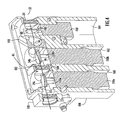
FIGs. 3 and4 , theOPO 30 may be embodied as a relatively small and compact device. Ahousing 100 made of material such as stainless steel contains the OPO components. Theoutput coupler 22 may be disposed within itsown housing 110 separate from themain housing 100 to provide degrees of freedom for alignment. The non-linearoptical crystals shafts 120a and 120b that are a part of therespective galvanometers etalon 40 is mounted to ashaft 140 that is attached to agalvanometer 150. Thegalvanometers respective crystals etalon 40 with respect to the propagation axis of theOPO 30, thereby changing (tuning or adjusting) the wavelength location of the signal and idler wavelength beams produced by thecrystals etalon 40 to achieve the desired wavelength tuning. A control unit (not shown but known in the art) generates galvanometer control signals to adjust the angles of the first and second non-linearoptical crystals etalon 40 and can facilitate tuning at rates up to 2 kHz for small step wavelength changes on the order of 10-20 nm. - The
galvanometers galvanometer 150 for the etalon may be a Cambridge Technology Model 6215 galvanometer. Thegalvanometers individual chambers housing 100. - The
filter 45 is held in position between the non-linearoptical crystals filter 45. Similarly, themirror 36 is held in position by amount 190 that encircles themirror 36 and is oriented at an angle with respect to the propagation axis. Finally, tFIG. 3 shows that thehousing 100 allows for very close coupling of the optical components and provides cooling in a "mono-block" assembly. Lengthening the cavity would be detrimental in the overall performance of theOPO 30. - The
wavelength tunable OPO 30 described herein may be used for a variety of applications. For example, it is useful as a multiple wavelength infrared source for detection of chemical/bio gases using Differential Absorption Lidar (DIAL) detection techniques, Differential Scattering (DISC) bio-aerosol lidar, explosive gas detection (leaks or exploration) of natural gas, methamphetamine lab detection and toxic industrial chemical detection. - A method for wavelength-agile laser light beam generation is also provided, comprising: introducing a pump laser light beam at a first wavelength into an optical cavity bounded by first and second optical elements positioned at opposite ends of the optical cavity; passing the pump energy through a non-linear optical medium disposed within the optical cavity to convert the pump energy into energy at a second wavelength and a third wavelength each of which is longer than the first wavelength; adjusting an angle of the non-linear optical medium relative to a propagation axis to control the apportionment of energy between the second and third wavelengths; reflecting light at the first and second wavelengths by the first optical element so that it passes back through the non-linear optical medium towards the second optical element; reflecting light at the first wavelength out of the optical cavity after it has been reflected back through the non-linear optical medium; directing light at the third wavelength through a narrow linewidth filter and to the second optical element; and reflecting light at the third wavelength by the second optical element back through the narrow linewidth filter, through the non-linear optical medium and out through the first optical element as an output beam.
- The apparatus and method described herein may be embodied in other specific forms without departing from the spirit or essential characteristics thereof. The foregoing embodiments are therefore to be considered in all respects illustrative and not meant to be limiting.
Claims (17)
- A wavelength-agile laser transmitter, comprising:a pump laser that is configured to output a pump beam at a first wavelength; andan optical parametric oscillator comprising:a non-linear optical medium configured to convert light at the first wavelength to light at a second wavelength and a third wavelength that are each longer than the first wavelength, an angle of the non-linear optical medium relative to a propagation axis of the optical parametric oscillator being adjustable to control apportionment of energy converted into light at the second and third wavelengths;a first optical element that is configured to receive the pump beam and direct it into a first end of the non-linear optical medium, wherein the first optical element is configured to be highly reflective at the second wavelength and highly transmissive at the third wavelength;a second optical element positioned proximate a second end of the non-linear optical medium, wherein the second optical element is configured to be highly reflective at the first and second wavelengths and highly transmissive at the third wavelength;an etalon positioned in proximate the first optical element, wherein the etalon is configured to narrow a linewidth of light that passes through it; and a third optical element that is positioned proximate the etalon and which is configured to be highly reflective at the third wavelength such that light at the third wavelength resonates between the etalon and the third optical element and passes through the first optical element into the non-linear optical medium where it interacts with light at the second wavelength;wherein an output beam corresponds to light that is transmitted through the second optical element at the third wavelength.
- A wavelength-agile laser transmitter apparatus, comprising:a pump laser that is configured to output a pump beam at a firstwavelength; anda cavity that serves as an optical parametric oscillator, the cavity containing: a non-linear optical medium configured to convert light at the first wavelength to light at a second wavelength and a third wavelength that are each longer than the first wavelength, an angle of the non-linear optical medium relative to a propagation axis of the optical parametric oscillator being adjustable to control apportionment of energy converted into light at the second and third wavelengths;a first optical element that is configured to receive the pump beam and direct it into a first end of the non-linear optical medium, wherein the first optical element is configured to be highly reflective at the second wavelength and highly transmissive at the third wavelength;a second optical element positioned proximate a second end of the non-linear optical medium, wherein the second optical element is configured to be highly reflective at the first and second wavelengths and highly transmissive at the third wavelength;a narrow linewidth filter positioned proximate the first optical element and configured to narrow a linewidth of light that passes through it; and a third optical element that is positioned proximate the narrow linewidth filter and which is configured to be highly reflective at the third wavelength such that light at the third wavelength resonates between the narrow linewidth filter and the third optical element and passes through the first optical element into the non-linear optical medium where it interacts with light at the second wavelength;wherein the first optical element and the second optical element cause light at the second wavelength to partially resonate in the optical parametric oscillator before the first optical element reflects the light at the second wavelength out of the optical parameter oscillator, and wherein the second optical element and the third optical element cause light at the third wavelength to partially resonate in the optical parametric oscillator before the second optical element allows light at the third wavelength to pass out of the optical parametric oscillator as an output beam.
- The device of claim 1 or 2, wherein the first optical element and the second optical element cause light at the second wavelength to partially resonate in the optical parametric oscillator before the first optical element reflects the light at the second wavelength out of the optical parameter oscillator, and wherein the second optical element and the third optical element cause light at the third wavelength to partially resonate in the optical parametric oscillator before the second optical element allows light at the third wavelength to pass out of the optical parametric oscillator as the output beam.
- The device of one of claims 1 to 3, wherein said non-linear optical medium comprises first and second non-linear optical crystals, each of the first and second non-linear optical crystals configured to convert light at said first wavelength into light at said second wavelength and said third wavelength, wherein an angle of each of the first and second non-linear optical crystals relative to the propagation axis of the optical parametric oscillator is adjustable to control apportionment of energy between the second and third wavelengths that each of the first and second non-linear optical crystals produces.
- The device of claim 4, wherein the optical parametric oscillator comprises a filter positioned between the first and second non-linear optical crystals, wherein the filter is configured to substantially reject light at said second wavelength.
- The device of claim 4 or 5, wherein the first and second non-linear optical crystals are periodically poled lithium niobate (PPLN) crystals.
- The device one of claims 4 to 6, and further comprising first and second galvanometers coupled to the first and second non-linear optical crystals, respectively, and being configured to adjust the angle of the first and second non-linear optical crystals, respectively, relative to the propagation axis of the optical parametric oscillator and particularly the first and second galvanometers are liquid-cooled, and/or particularly the first and second galvanometers for the first and second non-linear optical crystals are configured to be adjusted together.
- The device of one of the preceding claims, wherein the narrow linewidth filter is adjustable to control linewidth filter selection of light passing therethrough.
- The device of one of the preceding claims, and further comprising a housing that contains the optical parametric oscillator, said housing particularly comprises first, second and third chambers, said first and second chambers configured to contain galvanometers for first and second non-linear optical crystals, respectively.
- The device of claim 9, and further comprising a third galvanometer coupled to the etalon to adjust the position of the etalon in order to adjust the linewidth selection, and wherein the housing further comprises a third chamber configured to contain the third galvanometer.
- The device of claim 10, and further comprising a first arm that attaches the first non-linear optical crystal to the first galvanometer, a second arm that attaches the second non-linear optical crystal to the second galvanometer, and a third arm that attaches the etalon to the third galvanometer, wherein the first, second and third galvanometers rotate the first, second and third arm, respectively, in order to change the angle of first and second non-linear optical crystals and the etalon, respectively, relative to the propagation axis of the optical parametric oscillator.
- The device of one of the preceding claims, wherein the angle of the non-linear optical medium and the angle of the etalon are configured to adjust the third wavelength of light within a range of up to 500 nm.
- A wavelength-agile laser transmitter apparatus, comprising:means for outputting a pump light beam at a first wavelength; andmeans for containing a plurality of optical elements to support optical parametric oscillation therein, including:means for converting light at the first wavelength to light at a second wavelength and a third wavelength that are each longer than the first wavelength, wherein said means for converting being adjustable to control apportionment of energy converted into light at the second and third wavelengths;first optical means for receiving the pump beam and directing it into a first end of the means for converting and configured for being be highly reflective at the second wavelength and highly transmissive at the third wavelength;second optical means positioned proximate a second end of the means for converting and configured for being highly reflective at the first and second wavelengths and highly transmissive at the third wavelength;filtering means positioned proximate the first optical means and configured for narrowing a linewidth of light that passes through it; and a third optical means positioned proximate the filtering means and configured for being highly reflective at the third wavelength such that light at the third wavelength resonates between the filtering means and the third optical means and passes through the first optical means into the means for converting where it interacts with light at the second wavelength;wherein the first optical means and the second optical means cause light at the second wavelength to partially resonate in the means for containing before the first optical means reflects the light at the second wavelength out of the means for containing, and wherein the second optical means and the third optical means cause light at the third wavelength to partially resonate in the means for containing before the second optical means allows light at the third wavelength to pass out of the means for containing as an output beam.
- A method comprising:introducing a pump laser light beam at a first wavelength into an optical cavity bounded by first and second optical elements positioned at opposite ends of the optical cavity;passing the pump energy through a non-linear optical medium disposed within the optical cavity to convert the pump energy into energy at a second wavelength and a third wavelength each of which is longer than the first wavelength;adjusting an angle of the non-linear optical medium relative to a propagation axis to control the apportionment of energy between the second and third wavelengths;reflecting light at the first and second wavelengths by the first optical element so that it passes back through the non-linear optical medium towards the second optical element;reflecting light at the first wavelength out of the optical cavity after it has been reflected back through the non-linear optical medium;directing light at the third wavelength through a narrow linewidth filter and to the second optical element; andreflecting light at the third wavelength by the second optical element back through the narrow linewidth filter, through the non-linear optical medium and out through the first optical element as an output beam.
- The method of claim 14, and further comprising reflecting light at the second wavelength out of the cavity after it has partially resonated in the cavity, wherein reflecting light at the second wavelength particularly comprises reflecting light at the second wavelength after it has been reflected by the first optical element and has passed through the non-linear optical medium.
- The method of claim 14 or 15, wherein reflecting light at the third wavelength comprises reflecting the light at the third wavelength after it has partially resonated in the cavity before it passes out cavity through the first optical element as the output beam.
- The method of one of claims 14 to 16, and further comprising adjusting the narrow linewidth filter.
Applications Claiming Priority (1)
| Application Number | Priority Date | Filing Date | Title |
|---|---|---|---|
| US12/055,385 US7724788B2 (en) | 2008-03-26 | 2008-03-26 | Wavelength-agile laser transmitter using optical parametric oscillator |
Publications (3)
| Publication Number | Publication Date |
|---|---|
| EP2105789A2 true EP2105789A2 (en) | 2009-09-30 |
| EP2105789A3 EP2105789A3 (en) | 2010-06-09 |
| EP2105789B1 EP2105789B1 (en) | 2012-05-30 |
Family
ID=40602149
Family Applications (1)
| Application Number | Title | Priority Date | Filing Date |
|---|---|---|---|
| EP09153685A Expired - Fee Related EP2105789B1 (en) | 2008-03-26 | 2009-02-26 | Wavelength-agile laser transmitter using optical parametric oscillator |
Country Status (5)
| Country | Link |
|---|---|
| US (1) | US7724788B2 (en) |
| EP (1) | EP2105789B1 (en) |
| JP (1) | JP5489491B2 (en) |
| AU (1) | AU2009200826B2 (en) |
| CA (1) | CA2660263C (en) |
Families Citing this family (11)
| Publication number | Priority date | Publication date | Assignee | Title |
|---|---|---|---|---|
| KR101441008B1 (en) * | 2010-09-20 | 2014-09-17 | 한국전자통신연구원 | Optical transmission apparatus having temperature control capability |
| US8730566B2 (en) | 2011-03-17 | 2014-05-20 | Exelis Inc. | Grating based optical parametric oscillator and method of dynamically tuning the oscillator for generating desired optical signals |
| US9166721B2 (en) * | 2012-05-04 | 2015-10-20 | University Of Southern California | Reconfigurable optical transmitter |
| GB201210342D0 (en) * | 2012-06-12 | 2012-07-25 | Iti Scotland Scottish Entpr | Method and apparatus for tuning coherent radiation |
| US20140276672A1 (en) * | 2013-03-15 | 2014-09-18 | Amo Development Llc. | Stable mode-locked laser apparatus |
| CN103814886B (en) * | 2014-02-19 | 2015-06-10 | 北京交通大学 | Wavelength tuning light bird dispeller |
| GB2532496B (en) * | 2014-11-21 | 2017-04-05 | Coherent Scotland Ltd | Crystal-pair counter-rotator with translation capability |
| US9680286B2 (en) * | 2015-09-29 | 2017-06-13 | The United States Of America As Represented By The Administrator Of The National Aeronautics And Space Administration | Spectral and radiometric calibration using tunable lasers |
| DE102016107499A1 (en) * | 2016-04-22 | 2017-10-26 | Fraunhofer-Gesellschaft zur Förderung der angewandten Forschung e.V. | Frequency doubling and method for generating electromagnetic radiation |
| CN106099633A (en) * | 2016-07-07 | 2016-11-09 | 江苏师范大学 | The laser instrument that a kind of mid-infrared width wavestrip laser exports simultaneously |
| CN112731348B (en) * | 2020-12-23 | 2023-11-14 | 深圳砺剑天眼科技有限公司 | Multi-angle difference absorbing device based on laser radar |
Citations (2)
| Publication number | Priority date | Publication date | Assignee | Title |
|---|---|---|---|---|
| US6044094A (en) | 1997-03-19 | 2000-03-28 | Inrad | Laser system with optical parametric oscillator |
| US6751010B1 (en) | 2003-04-23 | 2004-06-15 | Itt Manufacturing Enterprises, Inc. | Low finesse, tri-etalon, optical parametric oscillator |
Family Cites Families (11)
| Publication number | Priority date | Publication date | Assignee | Title |
|---|---|---|---|---|
| JPH0346638A (en) * | 1989-07-14 | 1991-02-27 | Oyo Koden Kenkiyuushitsu:Kk | Optical parametric oscillator made of lib3o5 |
| US5594592A (en) * | 1994-03-30 | 1997-01-14 | Harlamoff; Brian L. | Narrow linewidth BBO optical parametric oscillator utilizing extraordinary resonance |
| JPH0990450A (en) * | 1995-09-26 | 1997-04-04 | Ishikawajima Harima Heavy Ind Co Ltd | Optical oscillator |
| US6016214A (en) * | 1998-09-11 | 2000-01-18 | Northrop Grumman Corporation | Quadruple grating period PPLN optical parametric oscillator difference frequency generator with common doubly resonant cavity |
| US6295160B1 (en) * | 1999-02-16 | 2001-09-25 | Opotek, Inc. | Broad tuning-range optical parametric oscillator |
| JP2000338531A (en) * | 1999-05-26 | 2000-12-08 | Toshiba Corp | Wavelength conversion laser device and laser radar device |
| JP2001085774A (en) * | 1999-09-09 | 2001-03-30 | Nec Corp | Variable wavelength laser and laser oscillation wavelength switching method |
| JP2004219675A (en) * | 2003-01-15 | 2004-08-05 | Bega:Kk | Far-infrared solid laser oscillation system |
| JP4583770B2 (en) * | 2004-01-26 | 2010-11-17 | 浜松ホトニクス株式会社 | Coherent light source |
| JP2006165340A (en) * | 2004-12-08 | 2006-06-22 | Tohoku Univ | Infrared light source |
| JP4960040B2 (en) * | 2006-08-11 | 2012-06-27 | 株式会社アドバンテスト | Light generation device and terahertz light generation device including the device |
-
2008
- 2008-03-26 US US12/055,385 patent/US7724788B2/en active Active - Reinstated
-
2009
- 2009-02-26 EP EP09153685A patent/EP2105789B1/en not_active Expired - Fee Related
- 2009-03-03 AU AU2009200826A patent/AU2009200826B2/en not_active Ceased
- 2009-03-04 JP JP2009051003A patent/JP5489491B2/en not_active Expired - Fee Related
- 2009-03-26 CA CA2660263A patent/CA2660263C/en active Active
Patent Citations (2)
| Publication number | Priority date | Publication date | Assignee | Title |
|---|---|---|---|---|
| US6044094A (en) | 1997-03-19 | 2000-03-28 | Inrad | Laser system with optical parametric oscillator |
| US6751010B1 (en) | 2003-04-23 | 2004-06-15 | Itt Manufacturing Enterprises, Inc. | Low finesse, tri-etalon, optical parametric oscillator |
Also Published As
| Publication number | Publication date |
|---|---|
| US7724788B2 (en) | 2010-05-25 |
| EP2105789A3 (en) | 2010-06-09 |
| AU2009200826A1 (en) | 2009-10-15 |
| JP2009237566A (en) | 2009-10-15 |
| JP5489491B2 (en) | 2014-05-14 |
| AU2009200826B2 (en) | 2010-11-25 |
| EP2105789B1 (en) | 2012-05-30 |
| US20090245297A1 (en) | 2009-10-01 |
| CA2660263A1 (en) | 2009-09-26 |
| CA2660263C (en) | 2013-07-16 |
Similar Documents
| Publication | Publication Date | Title |
|---|---|---|
| EP2105789B1 (en) | Wavelength-agile laser transmitter using optical parametric oscillator | |
| US5291503A (en) | Internally stimulated optical parametric oscillator/laser | |
| JP3909867B2 (en) | Laser equipment | |
| US8599476B1 (en) | Alignment and optimization of a synchronously pumped optical parametric oscillator for nonlinear optical generation | |
| US20090122816A1 (en) | Rapidly and electronically broadly tunable IR laser source | |
| JP3421184B2 (en) | Method of selecting wavelength in tunable laser and laser oscillating device capable of selecting wavelength in tunable laser | |
| US8094368B2 (en) | Optical parametric oscillator | |
| US5159487A (en) | Optical parametric oscillator OPO having a variable line narrowed output | |
| US6295160B1 (en) | Broad tuning-range optical parametric oscillator | |
| US20070297033A1 (en) | Hybrid nonlinear optical conversion and optical parametric oscillation | |
| US20060153255A1 (en) | Terahertz wave generation system | |
| AU3071699A (en) | Optical parametric oscillator with monolithic dual ppln elements with intrinsic mirrors | |
| US5781571A (en) | Optical parametric oscillator with porro prism cavity | |
| EP2500772A1 (en) | Grating based optical parametric oscillator and method of dynamically tuning the oscillator for generating desired optical signals | |
| JP2016218373A (en) | Multiwavelength oscillation type optical parametric oscillation device and multiwavelength oscillation type optical parametric oscillation method | |
| Andres et al. | Synchronously pumped femtosecond optical parametric oscillator of congruent and stoichiometric MgO-doped periodically poled lithium niobate | |
| Haidar et al. | Injection-seeded optical parametric oscillator for efficient difference frequency generation in mid-IR | |
| US6751010B1 (en) | Low finesse, tri-etalon, optical parametric oscillator | |
| JP4531163B2 (en) | Optical parametric oscillator | |
| Henriksson et al. | Tandem PPKTP and ZGP OPO for mid-infrared generation | |
| US7269189B2 (en) | Coherent light source based on sum-frequency mixing | |
| US9170470B1 (en) | Non-planer, image rotating optical parametric oscillator | |
| EP1952196A1 (en) | Laser source for the infrared wavelength range | |
| Favier et al. | Compact tunable laser source emitting in the LWIR for standoff gas sensing | |
| Perrett et al. | Spectral line narrowing in PPLN OPO devices for 1-µm wavelength doubling |
Legal Events
| Date | Code | Title | Description |
|---|---|---|---|
| PUAI | Public reference made under article 153(3) epc to a published international application that has entered the european phase |
Free format text: ORIGINAL CODE: 0009012 |
|
| AK | Designated contracting states |
Kind code of ref document: A2 Designated state(s): AT BE BG CH CY CZ DE DK EE ES FI FR GB GR HR HU IE IS IT LI LT LU LV MC MK MT NL NO PL PT RO SE SI SK TR |
|
| AX | Request for extension of the european patent |
Extension state: AL BA RS |
|
| PUAL | Search report despatched |
Free format text: ORIGINAL CODE: 0009013 |
|
| AK | Designated contracting states |
Kind code of ref document: A3 Designated state(s): AT BE BG CH CY CZ DE DK EE ES FI FR GB GR HR HU IE IS IT LI LT LU LV MC MK MT NL NO PL PT RO SE SI SK TR |
|
| AX | Request for extension of the european patent |
Extension state: AL BA RS |
|
| 17P | Request for examination filed |
Effective date: 20100727 |
|
| AKX | Designation fees paid |
Designated state(s): AT BE BG CH CY CZ DE DK EE ES FI FR GB GR HR HU IE IS IT LI LT LU LV MC MK MT NL NO PL PT RO SE SI SK TR |
|
| GRAJ | Information related to disapproval of communication of intention to grant by the applicant or resumption of examination proceedings by the epo deleted |
Free format text: ORIGINAL CODE: EPIDOSDIGR1 |
|
| GRAP | Despatch of communication of intention to grant a patent |
Free format text: ORIGINAL CODE: EPIDOSNIGR1 |
|
| GRAP | Despatch of communication of intention to grant a patent |
Free format text: ORIGINAL CODE: EPIDOSNIGR1 |
|
| RBV | Designated contracting states (corrected) |
Designated state(s): DE FR GB IT |
|
| RAP1 | Party data changed (applicant data changed or rights of an application transferred) |
Owner name: EXELIS, INC. |
|
| GRAS | Grant fee paid |
Free format text: ORIGINAL CODE: EPIDOSNIGR3 |
|
| GRAA | (expected) grant |
Free format text: ORIGINAL CODE: 0009210 |
|
| AK | Designated contracting states |
Kind code of ref document: B1 Designated state(s): DE FR GB IT |
|
| REG | Reference to a national code |
Ref country code: GB Ref legal event code: FG4D |
|
| REG | Reference to a national code |
Ref country code: DE Ref legal event code: R096 Ref document number: 602009007270 Country of ref document: DE Effective date: 20120726 |
|
| PLBE | No opposition filed within time limit |
Free format text: ORIGINAL CODE: 0009261 |
|
| STAA | Information on the status of an ep patent application or granted ep patent |
Free format text: STATUS: NO OPPOSITION FILED WITHIN TIME LIMIT |
|
| 26N | No opposition filed |
Effective date: 20130301 |
|
| REG | Reference to a national code |
Ref country code: DE Ref legal event code: R097 Ref document number: 602009007270 Country of ref document: DE Effective date: 20130301 |
|
| REG | Reference to a national code |
Ref country code: DE Ref legal event code: R082 Country of ref document: DE Representative=s name: PATENTANWAELTE MAGENBAUER & KOLLEGEN PARTNERSC, DE Ref document number: 602009007270 |
|
| REG | Reference to a national code |
Ref country code: FR Ref legal event code: PLFP Year of fee payment: 7 |
|
| REG | Reference to a national code |
Ref country code: FR Ref legal event code: PLFP Year of fee payment: 8 |
|
| PGFP | Annual fee paid to national office [announced via postgrant information from national office to epo] |
Ref country code: IT Payment date: 20160223 Year of fee payment: 8 |
|
| REG | Reference to a national code |
Ref country code: DE Ref legal event code: R081 Ref document number: 602009007270 Country of ref document: DE Owner name: HARRIS IT SERVICES CORPORATION (N.D.GES.D. STA, US Free format text: FORMER OWNER: EXELIS INC., MCLEAN, VA., US Ref country code: DE Ref legal event code: R082 Ref document number: 602009007270 Country of ref document: DE Representative=s name: PATENTANWAELTE MAGENBAUER & KOLLEGEN PARTNERSC, DE Ref country code: DE Ref legal event code: R081 Ref document number: 602009007270 Country of ref document: DE Owner name: EAGLE TECHNOLOGY, LLC (N.D.GES. DES STAATES DE, US Free format text: FORMER OWNER: EXELIS INC., MCLEAN, VA., US |
|
| REG | Reference to a national code |
Ref country code: FR Ref legal event code: PLFP Year of fee payment: 9 |
|
| REG | Reference to a national code |
Ref country code: GB Ref legal event code: 732E Free format text: REGISTERED BETWEEN 20170223 AND 20170303 |
|
| REG | Reference to a national code |
Ref country code: GB Ref legal event code: 732E Free format text: REGISTERED BETWEEN 20170305 AND 20170308 |
|
| REG | Reference to a national code |
Ref country code: GB Ref legal event code: 732E Free format text: REGISTERED BETWEEN 20170309 AND 20170315 |
|
| REG | Reference to a national code |
Ref country code: DE Ref legal event code: R082 Ref document number: 602009007270 Country of ref document: DE Representative=s name: PATENTANWAELTE MAGENBAUER & KOLLEGEN PARTNERSC, DE Ref country code: DE Ref legal event code: R081 Ref document number: 602009007270 Country of ref document: DE Owner name: HARRIS IT SERVICES CORPORATION (N.D.GES.D. STA, US Free format text: FORMER OWNER: EAGLE TECHNOLOGY, LLC (N.D.GES. DES STAATES DELAWARE), WILMINGTON, DEL., US |
|
| REG | Reference to a national code |
Ref country code: GB Ref legal event code: 732E Free format text: REGISTERED BETWEEN 20170629 AND 20170705 |
|
| REG | Reference to a national code |
Ref country code: FR Ref legal event code: TP Owner name: EAGLE TECHNOLOGY, LLC, US Effective date: 20170710 |
|
| REG | Reference to a national code |
Ref country code: FR Ref legal event code: TP Owner name: HARRIS IT SERVICES CORPORATION, US Effective date: 20171013 |
|
| REG | Reference to a national code |
Ref country code: FR Ref legal event code: PLFP Year of fee payment: 10 |
|
| PG25 | Lapsed in a contracting state [announced via postgrant information from national office to epo] |
Ref country code: IT Free format text: LAPSE BECAUSE OF NON-PAYMENT OF DUE FEES Effective date: 20170226 |
|
| PGFP | Annual fee paid to national office [announced via postgrant information from national office to epo] |
Ref country code: DE Payment date: 20190314 Year of fee payment: 11 Ref country code: GB Payment date: 20190221 Year of fee payment: 11 |
|
| PGFP | Annual fee paid to national office [announced via postgrant information from national office to epo] |
Ref country code: FR Payment date: 20190221 Year of fee payment: 11 |
|
| REG | Reference to a national code |
Ref country code: DE Ref legal event code: R119 Ref document number: 602009007270 Country of ref document: DE |
|
| GBPC | Gb: european patent ceased through non-payment of renewal fee |
Effective date: 20200226 |
|
| PG25 | Lapsed in a contracting state [announced via postgrant information from national office to epo] |
Ref country code: DE Free format text: LAPSE BECAUSE OF NON-PAYMENT OF DUE FEES Effective date: 20200901 Ref country code: FR Free format text: LAPSE BECAUSE OF NON-PAYMENT OF DUE FEES Effective date: 20200229 Ref country code: GB Free format text: LAPSE BECAUSE OF NON-PAYMENT OF DUE FEES Effective date: 20200226 |