EP2108398B1 - Implantable medical lead for electrical stimulation and method of manufacturing the same - Google Patents
Implantable medical lead for electrical stimulation and method of manufacturing the same Download PDFInfo
- Publication number
- EP2108398B1 EP2108398B1 EP09009522A EP09009522A EP2108398B1 EP 2108398 B1 EP2108398 B1 EP 2108398B1 EP 09009522 A EP09009522 A EP 09009522A EP 09009522 A EP09009522 A EP 09009522A EP 2108398 B1 EP2108398 B1 EP 2108398B1
- Authority
- EP
- European Patent Office
- Prior art keywords
- paddle
- electrode
- lead
- paddle portion
- stimulation
- Prior art date
- Legal status (The legal status is an assumption and is not a legal conclusion. Google has not performed a legal analysis and makes no representation as to the accuracy of the status listed.)
- Expired - Lifetime
Links
- 230000000638 stimulation Effects 0.000 title claims description 53
- 238000004519 manufacturing process Methods 0.000 title claims description 6
- 239000004020 conductor Substances 0.000 claims abstract description 34
- 210000000278 spinal cord Anatomy 0.000 claims description 31
- 238000000034 method Methods 0.000 claims description 15
- 210000001951 dura mater Anatomy 0.000 description 17
- 208000002193 Pain Diseases 0.000 description 15
- 210000001519 tissue Anatomy 0.000 description 11
- 230000006835 compression Effects 0.000 description 9
- 238000007906 compression Methods 0.000 description 9
- 229920002635 polyurethane Polymers 0.000 description 9
- 239000004814 polyurethane Substances 0.000 description 9
- 238000002513 implantation Methods 0.000 description 8
- 239000000463 material Substances 0.000 description 8
- 230000009467 reduction Effects 0.000 description 7
- 210000000578 peripheral nerve Anatomy 0.000 description 6
- 229920002379 silicone rubber Polymers 0.000 description 6
- 229910052709 silver Inorganic materials 0.000 description 6
- 239000004332 silver Substances 0.000 description 6
- BQCADISMDOOEFD-UHFFFAOYSA-N Silver Chemical compound [Ag] BQCADISMDOOEFD-UHFFFAOYSA-N 0.000 description 5
- 230000005284 excitation Effects 0.000 description 5
- 210000000944 nerve tissue Anatomy 0.000 description 5
- -1 polyethylene Polymers 0.000 description 5
- 238000012216 screening Methods 0.000 description 5
- 208000036829 Device dislocation Diseases 0.000 description 4
- 239000000835 fiber Substances 0.000 description 4
- 208000035824 paresthesia Diseases 0.000 description 4
- BASFCYQUMIYNBI-UHFFFAOYSA-N platinum Chemical compound [Pt] BASFCYQUMIYNBI-UHFFFAOYSA-N 0.000 description 4
- 239000004945 silicone rubber Substances 0.000 description 4
- 239000004698 Polyethylene Substances 0.000 description 3
- 239000000853 adhesive Substances 0.000 description 3
- 230000001070 adhesive effect Effects 0.000 description 3
- 230000008859 change Effects 0.000 description 3
- 230000008030 elimination Effects 0.000 description 3
- 238000003379 elimination reaction Methods 0.000 description 3
- 230000005012 migration Effects 0.000 description 3
- 238000013508 migration Methods 0.000 description 3
- 229920000573 polyethylene Polymers 0.000 description 3
- KDLHZDBZIXYQEI-UHFFFAOYSA-N Palladium Chemical compound [Pd] KDLHZDBZIXYQEI-UHFFFAOYSA-N 0.000 description 2
- 206010033799 Paralysis Diseases 0.000 description 2
- FOIXSVOLVBLSDH-UHFFFAOYSA-N Silver ion Chemical compound [Ag+] FOIXSVOLVBLSDH-UHFFFAOYSA-N 0.000 description 2
- 238000005299 abrasion Methods 0.000 description 2
- 230000002411 adverse Effects 0.000 description 2
- 230000002146 bilateral effect Effects 0.000 description 2
- 210000004556 brain Anatomy 0.000 description 2
- 210000000133 brain stem Anatomy 0.000 description 2
- 230000001684 chronic effect Effects 0.000 description 2
- 239000011248 coating agent Substances 0.000 description 2
- 238000000576 coating method Methods 0.000 description 2
- 238000005516 engineering process Methods 0.000 description 2
- 210000004705 lumbosacral region Anatomy 0.000 description 2
- 229910052751 metal Inorganic materials 0.000 description 2
- 239000002184 metal Substances 0.000 description 2
- 210000004126 nerve fiber Anatomy 0.000 description 2
- 230000008058 pain sensation Effects 0.000 description 2
- 229910052697 platinum Inorganic materials 0.000 description 2
- 229920001343 polytetrafluoroethylene Polymers 0.000 description 2
- 239000004810 polytetrafluoroethylene Substances 0.000 description 2
- 230000008569 process Effects 0.000 description 2
- 210000000273 spinal nerve root Anatomy 0.000 description 2
- 230000004936 stimulating effect Effects 0.000 description 2
- 230000001225 therapeutic effect Effects 0.000 description 2
- 241001269524 Dura Species 0.000 description 1
- 208000004404 Intractable Pain Diseases 0.000 description 1
- 208000008238 Muscle Spasticity Diseases 0.000 description 1
- 229910000566 Platinum-iridium alloy Inorganic materials 0.000 description 1
- 229910001260 Pt alloy Inorganic materials 0.000 description 1
- 206010041549 Spinal cord compression Diseases 0.000 description 1
- HZEWFHLRYVTOIW-UHFFFAOYSA-N [Ti].[Ni] Chemical compound [Ti].[Ni] HZEWFHLRYVTOIW-UHFFFAOYSA-N 0.000 description 1
- 230000001154 acute effect Effects 0.000 description 1
- 229910045601 alloy Inorganic materials 0.000 description 1
- 239000000956 alloy Substances 0.000 description 1
- 238000003491 array Methods 0.000 description 1
- 238000005452 bending Methods 0.000 description 1
- 210000005013 brain tissue Anatomy 0.000 description 1
- 238000010276 construction Methods 0.000 description 1
- 230000008878 coupling Effects 0.000 description 1
- 238000010168 coupling process Methods 0.000 description 1
- 238000005859 coupling reaction Methods 0.000 description 1
- 230000001419 dependent effect Effects 0.000 description 1
- 230000003292 diminished effect Effects 0.000 description 1
- 230000000694 effects Effects 0.000 description 1
- 229920001971 elastomer Polymers 0.000 description 1
- 230000006870 function Effects 0.000 description 1
- PCHJSUWPFVWCPO-UHFFFAOYSA-N gold Chemical compound [Au] PCHJSUWPFVWCPO-UHFFFAOYSA-N 0.000 description 1
- 229910052737 gold Inorganic materials 0.000 description 1
- 239000010931 gold Substances 0.000 description 1
- 238000002684 laminectomy Methods 0.000 description 1
- 230000003902 lesion Effects 0.000 description 1
- 239000003589 local anesthetic agent Substances 0.000 description 1
- 230000007774 longterm Effects 0.000 description 1
- 238000005259 measurement Methods 0.000 description 1
- 150000002739 metals Chemical class 0.000 description 1
- 238000012986 modification Methods 0.000 description 1
- 230000004048 modification Effects 0.000 description 1
- 230000007659 motor function Effects 0.000 description 1
- 238000000465 moulding Methods 0.000 description 1
- 229910001000 nickel titanium Inorganic materials 0.000 description 1
- 229910000510 noble metal Inorganic materials 0.000 description 1
- 230000009972 noncorrosive effect Effects 0.000 description 1
- 229910052763 palladium Inorganic materials 0.000 description 1
- HWLDNSXPUQTBOD-UHFFFAOYSA-N platinum-iridium alloy Chemical class [Ir].[Pt] HWLDNSXPUQTBOD-UHFFFAOYSA-N 0.000 description 1
- 229920000642 polymer Polymers 0.000 description 1
- 238000002360 preparation method Methods 0.000 description 1
- 230000007115 recruitment Effects 0.000 description 1
- 238000000926 separation method Methods 0.000 description 1
- 208000018198 spasticity Diseases 0.000 description 1
- 238000001356 surgical procedure Methods 0.000 description 1
- 238000012546 transfer Methods 0.000 description 1
- 238000012800 visualization Methods 0.000 description 1
Images


Classifications
-
- A—HUMAN NECESSITIES
- A61—MEDICAL OR VETERINARY SCIENCE; HYGIENE
- A61N—ELECTROTHERAPY; MAGNETOTHERAPY; RADIATION THERAPY; ULTRASOUND THERAPY
- A61N1/00—Electrotherapy; Circuits therefor
- A61N1/02—Details
- A61N1/04—Electrodes
- A61N1/05—Electrodes for implantation or insertion into the body, e.g. heart electrode
- A61N1/0551—Spinal or peripheral nerve electrodes
- A61N1/0553—Paddle shaped electrodes, e.g. for laminotomy
-
- Y—GENERAL TAGGING OF NEW TECHNOLOGICAL DEVELOPMENTS; GENERAL TAGGING OF CROSS-SECTIONAL TECHNOLOGIES SPANNING OVER SEVERAL SECTIONS OF THE IPC; TECHNICAL SUBJECTS COVERED BY FORMER USPC CROSS-REFERENCE ART COLLECTIONS [XRACs] AND DIGESTS
- Y10—TECHNICAL SUBJECTS COVERED BY FORMER USPC
- Y10T—TECHNICAL SUBJECTS COVERED BY FORMER US CLASSIFICATION
- Y10T29/00—Metal working
- Y10T29/49—Method of mechanical manufacture
- Y10T29/49002—Electrical device making
- Y10T29/49117—Conductor or circuit manufacturing
- Y10T29/49174—Assembling terminal to elongated conductor
Definitions
- the present invention generally relates to the field of implantable medical devices, and more particularly to a medical electrical lead providing improved implantation capabilities.
- Electrical stimulation of electrically excitable tissue such as the brain and/or nerve tissue of the spinal cord or peripheral nerve can result in pain reduction and/or elimination for a living organism having the electrical stimulation performed.
- electrically excitable tissue such as the brain and/or nerve tissue of the spinal cord or peripheral nerve
- medical leads having electrode contacts have been implanted near the spinal column of the human body to provide pain relief for chronic intractable pain.
- the nerve tissue within the spinal column is stimulated electrically to reduce pain sensations at other parts of the body.
- the parameters of the stimulation signals applied near the electrically excitable tissue are adjusted to optimize pain reduction or elimination.
- the area of excitation within the spinal column and the intensity of excitation can be varied by corresponding adjustment of the parameters of the stimulation signals.
- an array of electrodes may be implanted near the nerve tissue within the spinal column or peripheral nerve. Then, each of those electrodes can be configured to have a polarity such that the desired area of the nerve tissue within the spinal column is electrically stimulated.
- parameters of the respective stimulation signal applied on each of those implanted electrodes can be varied for a corresponding variation in the area of excitation within the spinal column and in the intensity of excitation at the pain site.
- a clinician who is knowledgeable of the effects of electrical stimulation may vary the parameters of the respective stimulation signal applied on each of the implanted electrodes. The patient may rate the effectiveness in pain reduction for each variation in the parameters of the stimulation signals. Then during chronic stimulation if electrical stimulation of nerve tissue does result in sufficient pain reduction for the patient, then the medical lead is implanted for the long term with stimulation signals having parameters that lead to optimized pain reduction for the particular patient.
- the conduit providing passage of the spinal cord in the lumbar vertebra provides more room for the spinal cord when compared to the conduit for the spinal cord in the cervical vertebra.
- the spinal cord In the lumbar region the spinal cord has a smaller diameter and therefore there is more room within the conduit of the lumbar vertebrae.
- One style is the percutaneously inserted lead, which is introduced through a Touhy needle.
- the implanting physician places the lead stimulating electrodes in an appropriate location using fluoroscopic visualization and the procedure is done under a local anesthetic.
- An example of this type of lead is disclosed in U.S. Pat. No. 4,379,462 issued to Borkan .
- Percutaneously inserted leads can be used for pain reduction/elimination, however, there are problems associated with these leads.
- Percutaneously inserted leads are difficult to anchor and have a tendency to become dislodged. Even if the initial placement is accurate, lead migration can occur which can adversely affect paresthesia. Further, if the percutaneously inserted lead migrates enough to touch an incoming dorsal root, this can be very painful for the patient. Additionally, the area in which the patient is experiencing pain can move. This is a significant problem since percutaneous leads provide only limited means to change the area of stimulation if the lead migrates or if the needs of the patient change. Such means include reconfiguring the electrodes providing stimulation or performing additional surgery to adjust the lead's position. This problem could be resolved by enlarging the electrodes to cover more spinal cord area, however, the electrodes must be made small enough to fit through a Touhy needle. Thus, the stimulation area for percutaneous leads remains consequently small and because of this even a slight movement of the lead, especially laterally, can adversely affect paresthesia.
- percutaneous leads are typically 1.27 mm (.050 inches) in diameter. Because of the limited space in the high cervical region, if the lead is inserted improperly or if the lead migrates when placed in the cervical region where the dura mater is very thin, the percutaneous lead could possibly cause compression of the dura mater into the spinal cord causing discomfort, excess pain, and even paralysis.
- the second basic spinal cord stimulation lead type is commonly referred to as a surgical lead and is surgically implanted in a procedure referred to as a laminotomy.
- An example of this type of lead is the RESUME® lead manufactured by Medtronic, Inc. of Minneapolis, Minn., the assignee of the present invention.
- This lead has four in-line electrodes located on a flat rectangular paddle at the distal end of the lead and the lead is normally implanted outside of the dura mater. Since leads of this type are surgically implanted, the size of the electrodes may be made larger than those of the percutaneously implanted leads. Further, various electrode combinations can be selected so that the area of stimulation may be moved along the midline of the spinal cord.
- the surgical lead can provide a broader stimulation pattern more suitable for midline and bilateral pain problems than the percutaneously inserted lead. Moreover, since it is surgically implanted it can be sutured to try and prevent dislodgement and reduce lead migration.
- Surgical leads are less affected by the problem of lead migration because of the shape and size of the paddle and sutures may stabilize the lead.
- the paddles are made of silicon rubber, which requires a thickness of approximately 1.778 mm (.070 inches).
- Current technology does not allow the manufacture of desirably thin silicone rubber paddles suitable for locations with small extradural spaces such as the high cervical region due to production tolerances, coverage specifications, and internal anti-stretch components, which must be added to make the lead less elastic.
- thin rubber coverage on silicon rubber paddles over internal components; such as the electrodes are known to lack durability. Since the physician is trying to fit a rectangular lead into a cylindrical passage there is the potential for compression of the dura mater on the spinal cord. Therefore, inserting this rectangular lead still risks compression of the dura mater into the spinal cord causing discomfort, excess pain, and even paralysis.
- US 6,052,608 is directed to an implantable medical electrode supporting at least one conductive contact having an edge portion and a rounded protrusion extending above the edge portion and adapted to contact a treatment site of a patient in use.
- the implantable medical lead described in that prior art document comprises a thin paddle comprising a first paddle portion, a second paddle portion, the second paddle portion having at least one aperture, and at least one electrode electrically connected to at least one conductor, said at least one electrode being disposed between the first paddle portion and the second paddle portion with a portion of the at least one electrode being conductively exposed through the at least one aperture.
- WO 99/56818 relates to medical leads having a plurality of electrode contacts.
- the present invention provides a medical lead comprised of a paddle.
- a first paddle portion having a cavity on the surface of the first paddle portion and a second paddle portion having generally the same shape as the cavity of the first paddle portion and at least one aperture.
- the at least one electrode is placed in the cavity of the first paddle portion and is disposed between the first paddle portion and the second paddle portion.
- the at least one electrode is disposed in such a way that a portion of the electrodes is conductively exposed through the at least one aperture.
- an implantable medical paddle lead for electrical stimulation comprising the following steps:
- the present invention is not limited to only high cervical implantation or spinal stimulation leads, and may be employed in many of various types of therapeutic or diagnostic devices including spinal cord, peripheral nerve, deep brain, and deep brain stem stimulation leads. It is to be further understood, moreover, the present invention may be employed in many of various types of therapeutic or diagnostic leads and is not limited only to the high cervical leads. For purposes of illustration only, however, the present invention is below described in the context of high cervical implantation leads.
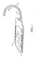
- FIG 1 is a plan view of one embodiment of a surgical lead of the present invention.
- Surgical lead 10 includes a pair of lead bodies 12 connected at their proximal end to a connector (not shown) of a type known in the art and at its distal end to a paddle 16.
- Lead bodies 12 can be made of any physiologically inert material such as silicone rubber or polyethylene; however, lead bodies 12 are preferable made of polyurethane so as to be compatible with paddle 16.
- Lead bodies 12 have lumens, which enclose at least one conductor 18 ( Figure 3 ) and most preferably have a diameter of 1.27 mm (.050 inches).
- Conductor 18 interconnects at least one electrode 20 located within paddle 16.
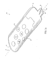
- Paddle 16 comprises a first paddle portion 22 and a second paddle portion 24.
- First paddle portion 22 is further comprised of a cavity 26 and apertures 28 to accept at least one lead body 12.
- Second paddle portion 24 has substantially the same shape as cavity 26 and is further comprised of openings 30. Cavity 26 is able to receive electrodes 20 within, which are electrically connected to conductors 18.
- Paddle 16 is preferably comprised of molded transparent polyurethane and has a thickness no greater than 0.762 mm (.030 inches). Thickness is defined as the measurement taken from the bottom surface of paddle 16 to the top surface of paddle 16. Due to the paddle's polyurethane construction paddle 16 is more durable than any other physiologically inert material such as silicone rubber or polyethylene. Further, paddle 16 has better coverage specifications such as reduced coverage requirements over encapsulated components due to the durability of polyurethene and does not require any extra internal components, such as anti-stretch devices, which can significantly add to the paddle's 16 thickness. It is contemplated that as technology in molding part tolerances and durability advances it may be possible to use other physiologically inert materials such as silicone rubber or polyethylene in the present invention and therefore their eventual use is contemplated.
- paddle 16 is curved about axial line A.
- the curvature in paddle 16 is substantially similar to the natural curvature of the dura mater over the spinal cord. Further, the flexibility of polyurethane allows paddle 16 to easily form around the dura mater of the spinal cord depending on whether paddle 16 is implanted outside or inside of the dura mater.
- the size and curvature of paddle 16 eliminates any excess pressure on the dura mater or the spinal cord.
- the paddle's thickness allows for ease of implantation with reduced risk of spinal compression.
- the base member's curvature eliminates excess spinal compression exhibited by inflexible rectangular paddle leads.
- First paddle portion 22 of the present invention has a plurality of electrodes 20 arrayed along the length and across the width of first paddle portion 22 specifically within cavity 26. Varieties of alternative arrays and numbers of electrodes are contemplated.
- Paddle 16 with the array of electrodes 20 transmits stimulation signals to surrounding human tissue.
- the implantable pulse generator ( Figure 5 ) provides respective stimulation signals having specified signal parameters to selected electrodes 20 in the array. Thus, depending on the desired location and amount of tissue stimulation needed, the parameters of the stimulation signals can be controlled and directed to selected electrode contacts for targeted stimulation.
- paddle 16 is placed outside the dura mater and stimulation occurs through the dura mater to the targeted tissue fibers within the spinal cord.
- paddle 16 has an array of eight electrodes 20 spaced axially along the length of first paddle portion 22 and laterally across the width. Electrode 20 sets upon first paddle portion 22 and protrudes slightly above the surface of plate body 24 in order to enhance tissue stimulation effectiveness. It is contemplated however, that electrode 20 can be recessed below the surface of second paddle portion 24.
- the array of electrodes 20 spans distant stimulation points, for example, nerve fibers, and at the same time provides combinations that cover stimulation points that may be close together. Because the epidural space restricts the width of any implanted body, the array of the present invention must span distant stimulation points to maximize the number of nerve fibers that are stimulated through the array. A clinician may direct stimulation to various combinations of stimulation points covered by the array of the present invention by controlling the amount and frequency to each electrode 20.
- first paddle portion 22 and second paddle portion 24 are fused together by injecting a volatile polyurethane adhesive inside of cavity 26.
- second paddle portion 24 is placed in cavity 26 with openings 30 accepting electrodes 20 within.
- the volatile polyurethane adhesive then begins to break down the polyurethane material of first paddle portion 22 and second paddle portion 24.
- the surfaces of cavity 26 and second paddle portion 24 begin to break down or liquefy, the polyurethane structures begin to run together and fuse. Thus, there is no longer two independent bodies, but only one paddle 16.
- Paddle 16 has a proximal end 90 and a distal end 92.
- Proximal end 90 provides openings 28 to accept at least one of the lead bodies 12 carrying conductors 18 into first paddle portion 22 and coupling to electrodes 20, which is discussed in more detail below.
- the distal end 92 is rounded and curved to prevent abrasion of human tissue for safer placement of the lead paddle at the desired stimulation area.
- the sides 94 of the paddle lead 16 are also rounded to prevent abrasion of tissue during implantation and while implanted.
- paddle 16 is curved laterally to match the curvature of the spinal cord dura mater. Curved paddle 16 enhances the likelihood of fiber stimulation by allowing electrodes 20 to be in close proximity to the targeted tissue fibers thus improving fiber recruitment.
- a curved paddle 16 reduces the potential for compression of the spinal cord.
- Conductor 18 is contained in lead body 12 and generally extends from the connector (not shown) to paddle 16.
- Conductor 18 can be manufactured from a wide range of materials that are electrically conductive such as nickel-titanium, platinum, gold, silver, palladium, other noble metals, and other alloys or metals suitable for use in the human body.
- low impedance is desired. Therefore, the core of each conductor is manufactured from low impedance metal such as silver and the jacket is manufactured from a material with good mechanical strength properties such as MP35N.
- Conductor 18 preferably has a resistance of less than 10/ohms/cm (3 ohms/foot) and a tensile strength greater than 5N, however, other resistances and tensile strengths are contemplated. Further, conductor 18 preferably is electrically insulated with a flouro-polymer such as ethyletetraflouroethylene or polytetrafluoroethylene (PTFE) with a coating thickness of approximately 0.0127 mm (0.0005 inch). In a preferred embodiment conductor 18 comprises a plurality of wires configured as braided strand wire (BSW) and is capable of reliably conducting electrical current after having been subject to numerous repeated bending and torquing stresses. BSW is available in many configurations including seven wire BSW.
- BSW braided strand wire
- Each wire preferably has a diameter of between about 0.002 and about 0.006 inches (0.0508- 0.1524 mm) and most preferably has a diameter of about 0.004 inches (0.1 mm).
- the number of conductors may be increased to two, three or more, dependent on need and generally to the number of electrical signals to be generated.
- the term "about” applies to all numeric values, whether or not explicitly indicated. The term “about” generally refers to a range of numbers that one of skill in the art would consider equivalent to the recited value (i.e., having the same function or result). In many instances, the term “about” may include numbers that are rounded to the nearest significant figure.
- Electrodes 20 are preferably formed of a non-corrosive, highly conductive material. Examples of such material include platinum and platinum alloys. Preferably, electrodes 20 are formed of a platinum-iridium alloy. As can be seen in Figures 3 & 4 , electrode 20 has a hat-like structure with top surface 104, an annular side surface 106, a base 108, and arches 110 & 112 which receive conduit 96 as discussed in more detail below. It is contemplated that electrode 20 can take on many structures including a flat structure as long as the structure is able to be held between first paddle portion and second paddle portion. Top surface 104 provides electrical contact with the tissue to be stimulated and preferably extends slightly beyond second paddle portion 24 as discussed above.
- Top surface 104 is also recessed to accommodate the dura mater of the spinal cord and thus further reduce any compression of the dura mater.
- Base 108 secures electrode 20 in-between first paddle portion 22 and second paddle portion 24. When first paddle portion 22 and second paddle portion 24 are attached as discussed above, base 108 is placed between the two and thus prevents electrode 20 from being easily dislodged.
- the size of electrodes 20 is preferably approximately 3 square millimeters. However, electrode contacts of other suitable sizes are contemplated and within the scope of this invention.
- conductor 18 is electrically attached to electrode 20 in a way, which provides improved strain relief. At the distal end of conductor 18 a portion of the conductor's coating is removed in preparation for attachment to electrode 20. Conductor 18 is then inserted approximately halfway through conduit 96 of crimp sleeve 98. By inserting conductor 18 approximately halfway through conduit 96 silver ion migration is mitigated. Previous connections connected the conductor directly to the electrode and if the conductor were comprised of silver the silver ions would pit or deteriorate the weld joint between the conductor and the electrode. This increased the chances of conductor separation and silver exposure to patient tissue. Next, crimp sleeve 98 is crimped to create a stable electrical attachment.
- crimp sleeve 98 is also used to provide a strong mechanical connection between conductor 18 and electrode 20.
- Crimp sleeve 98 is then laser welded to electrode 20 at arches 110 & 112 located at proximal end 100 and distal end 102 respectively. Therefore, the improved connection between electrode 20 and conductor 18 provides an improved mechanical connection as well as a reduction in silver ion migration.
- paddle 16 is adapted to be implanted in a human patient along the dorsal side of the spinal column 74.
- the lead is implanted over the midline of the spinal cord. If more than one electrode 20 is used then each electrode can be independently selectable so that when paddle 16 is positioned as shown a variety of stimulation patterns may be selected by providing stimulation signals to two or more of electrodes 20.
- An external pulse generator provides the stimulation signals or pulses during the screening procedure. After the initial electrode combination is selected, the lead is connected to an implanted pulse generator 76 by a lead extension 84.
- Lead extension 84 has a connector 77 at its distal end, which connects to connector 14 and has a plug-in connector 79 at its proximal end, which connects to pulse generator 76.
- Pulse generator 76 may be a fully implanted system such as the "ITREL I1"TM pulse generator available from Medtronic Inc.
- paddle 16 is designed to be implanted in the high cervical space where the space between the vertebrae and dura mater is very thin after the dura has been exposed by a partial laminectomy.
- the base member's reduced thickness and curved structure not only improve electrical stimulation capabilities, but also reduce the risk of spinal cord compression by allowing paddle 16 to move with the spinal environment in contrast to the flat paddle being so tightly inserted that it causes compression during movement.
- the invention will be described primarily in connection with its implantation in the high cervical space along the dorsal column for use in stimulating the spinal cord as a method of treating pain, it should be noted that paddle 16 could be used for any spinal cord stimulation application such as stimulation to induce motor function or to inhibit spasticity. When used for such other applications the lead could be implanted laterally or on the ventral side of the spinal column. The lead is also suitable for use in applications other than spinal cord stimulation such as stimulation of peripheral nerves.
- a screening procedure is performed to determine if the position of the lead will adequately supply paresthesia to the desired location.
- various electrode combinations are tested until the right combination is achieved.
- various unilateral and/or bilateral stimulation combinations are possible.
- the lead of the present invention provides the flexibility to make modifications to the area of paresthesia should the needs of the patient change or should there be any lead migration. This is done by changing the electrode combinations by external programming procedures well known in the art. Thus, the need for repositioning or removing the lead is greatly reduced.
Abstract
Description
- The present invention generally relates to the field of implantable medical devices, and more particularly to a medical electrical lead providing improved implantation capabilities.
- Electrical stimulation of electrically excitable tissue such as the brain and/or nerve tissue of the spinal cord or peripheral nerve can result in pain reduction and/or elimination for a living organism having the electrical stimulation performed. Thus, for example, medical leads having electrode contacts have been implanted near the spinal column of the human body to provide pain relief for chronic intractable pain. The nerve tissue within the spinal column is stimulated electrically to reduce pain sensations at other parts of the body.
- Depending on the location of the pain sensation, and the particularities of each different human body; the parameters of the stimulation signals applied near the electrically excitable tissue are adjusted to optimize pain reduction or elimination. For example, the area of excitation within the spinal column and the intensity of excitation can be varied by corresponding adjustment of the parameters of the stimulation signals.
- During acute trial stimulation, in order to vary the area of excitation, an array of electrodes may be implanted near the nerve tissue within the spinal column or peripheral nerve. Then, each of those electrodes can be configured to have a polarity such that the desired area of the nerve tissue within the spinal column is electrically stimulated. In addition, parameters of the respective stimulation signal applied on each of those implanted electrodes can be varied for a corresponding variation in the area of excitation within the spinal column and in the intensity of excitation at the pain site. Once the array of electrodes is implanted, a clinician who is knowledgeable of the effects of electrical stimulation may vary the parameters of the respective stimulation signal applied on each of the implanted electrodes. The patient may rate the effectiveness in pain reduction for each variation in the parameters of the stimulation signals. Then during chronic stimulation if electrical stimulation of nerve tissue does result in sufficient pain reduction for the patient, then the medical lead is implanted for the long term with stimulation signals having parameters that lead to optimized pain reduction for the particular patient.
- Although spinal stimulation has proven effective for pain relief, there are problems associated with it, especially stimulation in the high cervical region. The conduit providing passage of the spinal cord in the lumbar vertebra provides more room for the spinal cord when compared to the conduit for the spinal cord in the cervical vertebra. In the lumbar region the spinal cord has a smaller diameter and therefore there is more room within the conduit of the lumbar vertebrae. As the spinal cord traverses up through the lumbar region of the spine to the cervical region, more and more peripheral nerves come into the spinal cord at the dorsal roots and therefore there is less room within. This poses a significant problem when placing the stimulation leads since the space in which to place the leads is diminished substantially.
- Presently there are two basic styles of implantable leads available. One style is the percutaneously inserted lead, which is introduced through a Touhy needle. The implanting physician places the lead stimulating electrodes in an appropriate location using fluoroscopic visualization and the procedure is done under a local anesthetic. An example of this type of lead is disclosed in
U.S. Pat. No. 4,379,462 issued to Borkan . Percutaneously inserted leads can be used for pain reduction/elimination, however, there are problems associated with these leads. - Percutaneously inserted leads are difficult to anchor and have a tendency to become dislodged. Even if the initial placement is accurate, lead migration can occur which can adversely affect paresthesia. Further, if the percutaneously inserted lead migrates enough to touch an incoming dorsal root, this can be very painful for the patient. Additionally, the area in which the patient is experiencing pain can move. This is a significant problem since percutaneous leads provide only limited means to change the area of stimulation if the lead migrates or if the needs of the patient change. Such means include reconfiguring the electrodes providing stimulation or performing additional surgery to adjust the lead's position. This problem could be resolved by enlarging the electrodes to cover more spinal cord area, however, the electrodes must be made small enough to fit through a Touhy needle. Thus, the stimulation area for percutaneous leads remains consequently small and because of this even a slight movement of the lead, especially laterally, can adversely affect paresthesia.
- Another possible problem with percutaneous leads is their thickness is relatively large in comparison with the thickness of the dura mater in the high cervical region. Presently percutaneous leads are typically 1.27 mm (.050 inches) in diameter. Because of the limited space in the high cervical region, if the lead is inserted improperly or if the lead migrates when placed in the cervical region where the dura mater is very thin, the percutaneous lead could possibly cause compression of the dura mater into the spinal cord causing discomfort, excess pain, and even paralysis.
- The second basic spinal cord stimulation lead type is commonly referred to as a surgical lead and is surgically implanted in a procedure referred to as a laminotomy. An example of this type of lead is the RESUME® lead manufactured by Medtronic, Inc. of Minneapolis, Minn., the assignee of the present invention. This lead has four in-line electrodes located on a flat rectangular paddle at the distal end of the lead and the lead is normally implanted outside of the dura mater. Since leads of this type are surgically implanted, the size of the electrodes may be made larger than those of the percutaneously implanted leads. Further, various electrode combinations can be selected so that the area of stimulation may be moved along the midline of the spinal cord. The surgical lead can provide a broader stimulation pattern more suitable for midline and bilateral pain problems than the percutaneously inserted lead. Moreover, since it is surgically implanted it can be sutured to try and prevent dislodgement and reduce lead migration.
- Surgical leads are less affected by the problem of lead migration because of the shape and size of the paddle and sutures may stabilize the lead. However, presently the paddles are made of silicon rubber, which requires a thickness of approximately 1.778 mm (.070 inches). Current technology does not allow the manufacture of desirably thin silicone rubber paddles suitable for locations with small extradural spaces such as the high cervical region due to production tolerances, coverage specifications, and internal anti-stretch components, which must be added to make the lead less elastic. Further, thin rubber coverage on silicon rubber paddles over internal components; such as the electrodes, are known to lack durability. Since the physician is trying to fit a rectangular lead into a cylindrical passage there is the potential for compression of the dura mater on the spinal cord. Therefore, inserting this rectangular lead still risks compression of the dura mater into the spinal cord causing discomfort, excess pain, and even paralysis.
-
US 6,052,608 is directed to an implantable medical electrode supporting at least one conductive contact having an edge portion and a rounded protrusion extending above the edge portion and adapted to contact a treatment site of a patient in use. - The implantable medical lead described in that prior art document comprises a thin paddle comprising a first paddle portion, a second paddle portion, the second paddle portion having at least one aperture, and at least one electrode electrically connected to at least one conductor, said at least one electrode being disposed between the first paddle portion and the second paddle portion with a portion of the at least one electrode being conductively exposed through the at least one aperture.
-
WO 99/56818 - Therefore, what is clearly needed is a method and apparatus for lead implantation in the high cervical region, which provides both improved fixation to prevent migration and an improved paddle structure to prevent compression of the dura mater against the spinal cord. What is further needed is a method for producing a thin paddle lead having improved fixation for implantation in the high cervical region.
- The present invention provides a medical lead comprised of a paddle. A first paddle portion having a cavity on the surface of the first paddle portion and a second paddle portion having generally the same shape as the cavity of the first paddle portion and at least one aperture. There is at least one electrode electrically connected to at least one conductor. The at least one electrode is placed in the cavity of the first paddle portion and is disposed between the first paddle portion and the second paddle portion. The at least one electrode is disposed in such a way that a portion of the electrodes is conductively exposed through the at least one aperture.
- In another embodiment of the present invention, there is provided a method of manufacturing an implantable medical paddle lead for electrical stimulation, the method comprising the following steps:
- creating a first paddle portion having a cavity on one side and an inlet for receiving at least one conductor;
- creating a second paddle portion wherein the second paddle portion has generally the same shape as the cavity and has at least one aperture;
- placing at least one electrode in the cavity of the first paddle portion;
- connecting the at least one electrode to at least one conductor;
- placing the second paddle portion within the cavity of the first paddle portion wherein the at least one electrode is positioned between the first paddle portion and the second paddle portion, a portion of the at least one electrode being conductively exposed through the at least one aperture; and
- connecting the second paddle portion to the first paddle portion, wherein the paddle has a thickness up to 0,762 mm (.030 inches).
-
-
Figure 1 is a plan view of one embodiment of the surgical lead of the present invention; -
Figure 2 is an exploded top side view illustrating an improved surgical lead of the present invention; -
Figure 2a is a top side view illustrating an improved surgical lead of the present invention; -
Figure 3 is a top side view of an embodiment of an improved connection between a conductor and an electrode; -
Figure 4 is a bottom side view of an embodiment of an improved connection between a conductor and an electrode; -
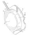
Figure 5 is a partial schematic view of the spinal cord of a patient with the implanted surgical lead paddle ofFigure 2 connected to a pulse generator; -
Figure 6 is a cross sectional view schematically illustrating the spinal column of a patient with the base member ofFigure 2 positioned on the dorsal side thereof; - To assist in an understanding of the invention, a preferred embodiment or embodiments will now be described in detail, by way of example only. Reference will be frequently taken to the figures, which are summarized above. Reference numerals will be used to indicate certain parts and locations in the figures. The same reference numerals will be used to indicate the same parts or locations throughout the figures unless otherwise indicated.
- The present invention is not limited to only high cervical implantation or spinal stimulation leads, and may be employed in many of various types of therapeutic or diagnostic devices including spinal cord, peripheral nerve, deep brain, and deep brain stem stimulation leads. It is to be further understood, moreover, the present invention may be employed in many of various types of therapeutic or diagnostic leads and is not limited only to the high cervical leads. For purposes of illustration only, however, the present invention is below described in the context of high cervical implantation leads.
-
Figure 1 is a plan view of one embodiment of a surgical lead of the present invention.Surgical lead 10 includes a pair oflead bodies 12 connected at their proximal end to a connector (not shown) of a type known in the art and at its distal end to apaddle 16. Leadbodies 12 can be made of any physiologically inert material such as silicone rubber or polyethylene; however, leadbodies 12 are preferable made of polyurethane so as to be compatible withpaddle 16. Leadbodies 12 have lumens, which enclose at least one conductor 18 (Figure 3 ) and most preferably have a diameter of 1.27 mm (.050 inches).Conductor 18 interconnects at least oneelectrode 20 located withinpaddle 16. - Referring to
Fig. 2 , an exemplary embodiment of apaddle 16 for spinal cord, peripheral nerve, deep brain, and brain stem stimulation of the present invention is shown.Paddle 16 comprises afirst paddle portion 22 and a second paddle portion 24.First paddle portion 22 is further comprised of acavity 26 andapertures 28 to accept at least onelead body 12. Second paddle portion 24 has substantially the same shape ascavity 26 and is further comprised ofopenings 30.Cavity 26 is able to receiveelectrodes 20 within, which are electrically connected toconductors 18. -
Paddle 16 is preferably comprised of molded transparent polyurethane and has a thickness no greater than 0.762 mm (.030 inches). Thickness is defined as the measurement taken from the bottom surface ofpaddle 16 to the top surface ofpaddle 16. Due to the paddle'spolyurethane construction paddle 16 is more durable than any other physiologically inert material such as silicone rubber or polyethylene. Further, paddle 16 has better coverage specifications such as reduced coverage requirements over encapsulated components due to the durability of polyurethene and does not require any extra internal components, such as anti-stretch devices, which can significantly add to the paddle's 16 thickness. It is contemplated that as technology in molding part tolerances and durability advances it may be possible to use other physiologically inert materials such as silicone rubber or polyethylene in the present invention and therefore their eventual use is contemplated. - As can be seen from
Figure 2 , paddle 16 is curved about axial line A. The curvature inpaddle 16 is substantially similar to the natural curvature of the dura mater over the spinal cord. Further, the flexibility of polyurethane allowspaddle 16 to easily form around the dura mater of the spinal cord depending on whetherpaddle 16 is implanted outside or inside of the dura mater. The size and curvature ofpaddle 16 eliminates any excess pressure on the dura mater or the spinal cord. First, the paddle's thickness allows for ease of implantation with reduced risk of spinal compression. Second, the base member's curvature eliminates excess spinal compression exhibited by inflexible rectangular paddle leads. -
First paddle portion 22 of the present invention has a plurality ofelectrodes 20 arrayed along the length and across the width offirst paddle portion 22 specifically withincavity 26. Varieties of alternative arrays and numbers of electrodes are contemplated.Paddle 16 with the array ofelectrodes 20 transmits stimulation signals to surrounding human tissue. The implantable pulse generator (Figure 5 ) provides respective stimulation signals having specified signal parameters to selectedelectrodes 20 in the array. Thus, depending on the desired location and amount of tissue stimulation needed, the parameters of the stimulation signals can be controlled and directed to selected electrode contacts for targeted stimulation. Typically, for spinal cord stimulation, paddle 16 is placed outside the dura mater and stimulation occurs through the dura mater to the targeted tissue fibers within the spinal cord. - Referring to
Fig. 2a , as most preferred, paddle 16 has an array of eightelectrodes 20 spaced axially along the length offirst paddle portion 22 and laterally across the width.Electrode 20 sets uponfirst paddle portion 22 and protrudes slightly above the surface of plate body 24 in order to enhance tissue stimulation effectiveness. It is contemplated however, thatelectrode 20 can be recessed below the surface of second paddle portion 24. The array ofelectrodes 20 spans distant stimulation points, for example, nerve fibers, and at the same time provides combinations that cover stimulation points that may be close together. Because the epidural space restricts the width of any implanted body, the array of the present invention must span distant stimulation points to maximize the number of nerve fibers that are stimulated through the array. A clinician may direct stimulation to various combinations of stimulation points covered by the array of the present invention by controlling the amount and frequency to eachelectrode 20. - With reference again to
Figure 2a , a preferred paddle of the present invention is shown. Preferably,first paddle portion 22 and second paddle portion 24 are fused together by injecting a volatile polyurethane adhesive inside ofcavity 26. After injecting the volatile polyurethane adhesive intocavity 26, second paddle portion 24 is placed incavity 26 withopenings 30 acceptingelectrodes 20 within. The volatile polyurethane adhesive then begins to break down the polyurethane material offirst paddle portion 22 and second paddle portion 24. As the surfaces ofcavity 26 and second paddle portion 24 begin to break down or liquefy, the polyurethane structures begin to run together and fuse. Thus, there is no longer two independent bodies, but only onepaddle 16. -
Paddle 16 has aproximal end 90 and adistal end 92.Proximal end 90 providesopenings 28 to accept at least one of thelead bodies 12 carryingconductors 18 intofirst paddle portion 22 and coupling toelectrodes 20, which is discussed in more detail below. Thedistal end 92 is rounded and curved to prevent abrasion of human tissue for safer placement of the lead paddle at the desired stimulation area. Thesides 94 of thepaddle lead 16 are also rounded to prevent abrasion of tissue during implantation and while implanted. As discussed above, paddle 16 is curved laterally to match the curvature of the spinal cord dura mater.Curved paddle 16 enhances the likelihood of fiber stimulation by allowingelectrodes 20 to be in close proximity to the targeted tissue fibers thus improving fiber recruitment. Moreover, as discussed above, acurved paddle 16 reduces the potential for compression of the spinal cord. - With reference to
Figures 3 &4 , a preferred embodiment of an improved connection betweenconductor 18 andelectrode 20 is shown.Conductor 18 is contained inlead body 12 and generally extends from the connector (not shown) to paddle 16.Conductor 18 can be manufactured from a wide range of materials that are electrically conductive such as nickel-titanium, platinum, gold, silver, palladium, other noble metals, and other alloys or metals suitable for use in the human body. However, in a preferred embodiment low impedance is desired. Therefore, the core of each conductor is manufactured from low impedance metal such as silver and the jacket is manufactured from a material with good mechanical strength properties such as MP35N.Conductor 18 preferably has a resistance of less than 10/ohms/cm (3 ohms/foot) and a tensile strength greater than 5N, however, other resistances and tensile strengths are contemplated. Further,conductor 18 preferably is electrically insulated with a flouro-polymer such as ethyletetraflouroethylene or polytetrafluoroethylene (PTFE) with a coating thickness of approximately 0.0127 mm (0.0005 inch). In apreferred embodiment conductor 18 comprises a plurality of wires configured as braided strand wire (BSW) and is capable of reliably conducting electrical current after having been subject to numerous repeated bending and torquing stresses. BSW is available in many configurations including seven wire BSW. Three wires, however, have been discovered to provide the best overall combination of maximum strength, minimum diameter, and maximum torque transfer between proximal and distal ends. Each wire preferably has a diameter of between about 0.002 and about 0.006 inches (0.0508- 0.1524 mm) and most preferably has a diameter of about 0.004 inches (0.1 mm). The number of conductors may be increased to two, three or more, dependent on need and generally to the number of electrical signals to be generated. The term "about" applies to all numeric values, whether or not explicitly indicated. The term "about" generally refers to a range of numbers that one of skill in the art would consider equivalent to the recited value (i.e., having the same function or result). In many instances, the term "about" may include numbers that are rounded to the nearest significant figure. -
Electrodes 20 are preferably formed of a non-corrosive, highly conductive material. Examples of such material include platinum and platinum alloys. Preferably,electrodes 20 are formed of a platinum-iridium alloy. As can be seen inFigures 3 &4 ,electrode 20 has a hat-like structure with top surface 104, anannular side surface 106, abase 108, andarches 110 & 112 which receiveconduit 96 as discussed in more detail below. It is contemplated thatelectrode 20 can take on many structures including a flat structure as long as the structure is able to be held between first paddle portion and second paddle portion. Top surface 104 provides electrical contact with the tissue to be stimulated and preferably extends slightly beyond second paddle portion 24 as discussed above. Top surface 104 is also recessed to accommodate the dura mater of the spinal cord and thus further reduce any compression of the dura mater.Base 108 secureselectrode 20 in-betweenfirst paddle portion 22 and second paddle portion 24. Whenfirst paddle portion 22 and second paddle portion 24 are attached as discussed above,base 108 is placed between the two and thus preventselectrode 20 from being easily dislodged. Preferably and based on past studies to reduce the potential of lesions from smaller contact areas, the size ofelectrodes 20 is preferably approximately 3 square millimeters. However, electrode contacts of other suitable sizes are contemplated and within the scope of this invention. - In a preferred configuration,
conductor 18 is electrically attached toelectrode 20 in a way, which provides improved strain relief. At the distal end of conductor 18 a portion of the conductor's coating is removed in preparation for attachment toelectrode 20.Conductor 18 is then inserted approximately halfway throughconduit 96 ofcrimp sleeve 98. By insertingconductor 18 approximately halfway throughconduit 96 silver ion migration is mitigated. Previous connections connected the conductor directly to the electrode and if the conductor were comprised of silver the silver ions would pit or deteriorate the weld joint between the conductor and the electrode. This increased the chances of conductor separation and silver exposure to patient tissue. Next, crimpsleeve 98 is crimped to create a stable electrical attachment. Since, silver material is not ideal for forming a strong mechanicalconnection crimp sleeve 98 is also used to provide a strong mechanical connection betweenconductor 18 andelectrode 20.Crimp sleeve 98 is then laser welded to electrode 20 atarches 110 & 112 located atproximal end 100 anddistal end 102 respectively. Therefore, the improved connection betweenelectrode 20 andconductor 18 provides an improved mechanical connection as well as a reduction in silver ion migration. - As shown in
Figures 5 &6 , paddle 16 is adapted to be implanted in a human patient along the dorsal side of thespinal column 74. As best seen inFigure 5 , typically the lead is implanted over the midline of the spinal cord. If more than oneelectrode 20 is used then each electrode can be independently selectable so that whenpaddle 16 is positioned as shown a variety of stimulation patterns may be selected by providing stimulation signals to two or more ofelectrodes 20. An external pulse generator provides the stimulation signals or pulses during the screening procedure. After the initial electrode combination is selected, the lead is connected to an implantedpulse generator 76 by alead extension 84. Leadextension 84 has aconnector 77 at its distal end, which connects toconnector 14 and has a plug-in connector 79 at its proximal end, which connects topulse generator 76.Pulse generator 76 may be a fully implanted system such as the "ITREL I1"™ pulse generator available from Medtronic Inc. - In use, paddle 16 is designed to be implanted in the high cervical space where the space between the vertebrae and dura mater is very thin after the dura has been exposed by a partial laminectomy. As can be appreciated the base member's reduced thickness and curved structure not only improve electrical stimulation capabilities, but also reduce the risk of spinal cord compression by allowing
paddle 16 to move with the spinal environment in contrast to the flat paddle being so tightly inserted that it causes compression during movement. Although the invention will be described primarily in connection with its implantation in the high cervical space along the dorsal column for use in stimulating the spinal cord as a method of treating pain, it should be noted thatpaddle 16 could be used for any spinal cord stimulation application such as stimulation to induce motor function or to inhibit spasticity. When used for such other applications the lead could be implanted laterally or on the ventral side of the spinal column. The lead is also suitable for use in applications other than spinal cord stimulation such as stimulation of peripheral nerves. - As discussed above, once the lead has been implanted a screening procedure is performed to determine if the position of the lead will adequately supply paresthesia to the desired location. During the screening process, various electrode combinations are tested until the right combination is achieved. By using the lead of the present invention various unilateral and/or bilateral stimulation combinations are possible.
- After the screening process is completed and the lead is properly anchored in place the lead is disconnected from the external screening device and connected to the implanted pulse generator so that the entire system can be internalized. Once the stimulation system has been internalized the lead of the present invention provides the flexibility to make modifications to the area of paresthesia should the needs of the patient change or should there be any lead migration. This is done by changing the electrode combinations by external programming procedures well known in the art. Thus, the need for repositioning or removing the lead is greatly reduced.
Claims (7)
- A method of manufacturing an implantable medical paddle lead for electrical stimulation, the method comprising the following steps:creating a first paddle portion (22) having a cavity (26) on one side and an inlet for receiving at least one conductor;creating a second paddle portion (24) wherein the second paddle portion has generally the same shape as the cavity and has at least one aperture (28);placing at least one electrode (20) in the cavity of the first paddle portion;connecting the at least one electrode (20) to at least one conductor (18);placing the second paddle portion within the cavity of the first paddle portion wherein the at least one electrode is positioned between the first paddle portion and the second paddle portion, a portion of the at least one electrode being conductively exposed through the at least one aperture; andconnecting the second paddle portion to the first paddle portion, wherein the paddle has a thickness up to 0.762 mm (.030 inches).
- The method of claim 1 wherein the paddle is curved along a vertical axis.
- The method of claim 2 wherein the curved paddle is substantially similar to the shape of the human spinal cord.
- The method of claim 1 wherein said paddle has a thickness up to 0.635 mm (.025 inches).
- The method of claim 1 wherein said paddle has a thickness up to 0.508 mm (.020 inches).
- An implantable medical lead for electrical stimulation, comprising: a paddle, comprising:a first paddle portion (22) having a cavity (26);a second paddle portion (24) having generally the same shape as the cavity of the first paddle portion and at least one aperture (28); andat least one electrode (20) electrically connected to at least one conductor (18), said at least one electrode placed in the cavity of the first paddle portion; said at least one electrode being disposed between the first paddle portion and the second paddle portion with a portion of the at least one electrode being conductively exposed through the at least one aperture.
- The implantable medical lead of claim 6 wherein the paddle has a thickness for application to a human spinal cord.
Applications Claiming Priority (2)
| Application Number | Priority Date | Filing Date | Title |
|---|---|---|---|
| US10/131,980 US7697995B2 (en) | 2002-04-25 | 2002-04-25 | Surgical lead paddle |
| EP03724273A EP1536857A2 (en) | 2002-04-25 | 2003-04-24 | Implantable medical lead for electrical stimulation and method of manufacturing the same |
Related Parent Applications (2)
| Application Number | Title | Priority Date | Filing Date |
|---|---|---|---|
| EP03724273.2 Division | 2003-04-24 | ||
| EP03724273A Division EP1536857A2 (en) | 2002-04-25 | 2003-04-24 | Implantable medical lead for electrical stimulation and method of manufacturing the same |
Publications (2)
| Publication Number | Publication Date |
|---|---|
| EP2108398A1 EP2108398A1 (en) | 2009-10-14 |
| EP2108398B1 true EP2108398B1 (en) | 2010-12-29 |
Family
ID=29248663
Family Applications (2)
| Application Number | Title | Priority Date | Filing Date |
|---|---|---|---|
| EP09009522A Expired - Lifetime EP2108398B1 (en) | 2002-04-25 | 2003-04-24 | Implantable medical lead for electrical stimulation and method of manufacturing the same |
| EP03724273A Withdrawn EP1536857A2 (en) | 2002-04-25 | 2003-04-24 | Implantable medical lead for electrical stimulation and method of manufacturing the same |
Family Applications After (1)
| Application Number | Title | Priority Date | Filing Date |
|---|---|---|---|
| EP03724273A Withdrawn EP1536857A2 (en) | 2002-04-25 | 2003-04-24 | Implantable medical lead for electrical stimulation and method of manufacturing the same |
Country Status (6)
| Country | Link |
|---|---|
| US (3) | US7697995B2 (en) |
| EP (2) | EP2108398B1 (en) |
| AT (1) | ATE493168T1 (en) |
| AU (1) | AU2003231143A1 (en) |
| DE (1) | DE60335581D1 (en) |
| WO (1) | WO2003090851A2 (en) |
Cited By (6)
| Publication number | Priority date | Publication date | Assignee | Title |
|---|---|---|---|---|
| US9572975B2 (en) | 2014-09-02 | 2017-02-21 | Cardiac Pacemakers, Inc. | Paddle leads configured for suture fixation |
| US9616219B2 (en) | 2014-09-16 | 2017-04-11 | Cardiac Pacemakers, Inc. | Paddle leads having asymmetric electrode configurations |
| US9763582B2 (en) | 2014-06-19 | 2017-09-19 | Cardiac Pacemakers, Inc. | Baroreceptor mapping system |
| US9795778B2 (en) | 2013-07-14 | 2017-10-24 | Cardiac Pacemakers, Inc. | Multi-electrode lead with backing for mecho/baroreceptor stimulation |
| US9839785B2 (en) | 2013-12-13 | 2017-12-12 | Cardiac Pacemakers, Inc. | Surgical instrument for implanting leads for baroreceptor stimulation therapy |
| US10029091B2 (en) | 2014-02-20 | 2018-07-24 | Cardiac Pacemakers, Inc. | Apparatus for baroreceptor stimulation therapy |
Families Citing this family (107)
| Publication number | Priority date | Publication date | Assignee | Title |
|---|---|---|---|---|
| US7797057B2 (en) * | 2002-10-23 | 2010-09-14 | Medtronic, Inc. | Medical paddle lead and method for spinal cord stimulation |
| US7499755B2 (en) * | 2002-10-23 | 2009-03-03 | Medtronic, Inc. | Paddle-style medical lead and method |
| US6999820B2 (en) * | 2003-05-29 | 2006-02-14 | Advanced Neuromodulation Systems, Inc. | Winged electrode body for spinal cord stimulation |
| US7107104B2 (en) * | 2003-05-30 | 2006-09-12 | Medtronic, Inc. | Implantable cortical neural lead and method |
| WO2005028025A1 (en) * | 2003-09-16 | 2005-03-31 | Advanced Bionics Corporation | Axial to planar lead conversion device and method |
| US7930037B2 (en) * | 2003-09-30 | 2011-04-19 | Medtronic, Inc. | Field steerable electrical stimulation paddle, lead system, and medical device incorporating the same |
| US20050084072A1 (en) | 2003-10-17 | 2005-04-21 | Jmp Industries, Inc., An Ohio Corporation | Collimator fabrication |
| US7437197B2 (en) * | 2003-10-23 | 2008-10-14 | Medtronic, Inc. | Medical lead and manufacturing method therefor |
| US8060207B2 (en) | 2003-12-22 | 2011-11-15 | Boston Scientific Scimed, Inc. | Method of intravascularly delivering stimulation leads into direct contact with tissue |
| US20050137646A1 (en) * | 2003-12-22 | 2005-06-23 | Scimed Life Systems, Inc. | Method of intravascularly delivering stimulation leads into brain |
| US7295875B2 (en) * | 2004-02-20 | 2007-11-13 | Boston Scientific Scimed, Inc. | Method of stimulating/sensing brain with combination of intravascularly and non-vascularly delivered leads |
| US7590454B2 (en) | 2004-03-12 | 2009-09-15 | Boston Scientific Neuromodulation Corporation | Modular stimulation lead network |
| US7177702B2 (en) * | 2004-03-12 | 2007-02-13 | Scimed Life Systems, Inc. | Collapsible/expandable electrode leads |
| US20050203600A1 (en) | 2004-03-12 | 2005-09-15 | Scimed Life Systems, Inc. | Collapsible/expandable tubular electrode leads |
| US7286879B2 (en) * | 2004-07-16 | 2007-10-23 | Boston Scientific Scimed, Inc. | Method of stimulating fastigium nucleus to treat neurological disorders |
| US7937160B2 (en) | 2004-12-10 | 2011-05-03 | Boston Scientific Neuromodulation Corporation | Methods for delivering cortical electrode leads into patient's head |
| CN101287411B (en) * | 2005-04-28 | 2013-03-06 | 普罗秋斯生物医学公司 | Pharma-informatics system |
| US8700178B2 (en) | 2005-12-27 | 2014-04-15 | Boston Scientific Neuromodulation Corporation | Stimulator leads and methods for lead fabrication |
| US7672734B2 (en) * | 2005-12-27 | 2010-03-02 | Boston Scientific Neuromodulation Corporation | Non-linear electrode array |
| US7835803B1 (en) * | 2006-01-17 | 2010-11-16 | Boston Scientific Neuromodulation Corporation | Lead assemblies with one or more switching networks |
| ATE428468T1 (en) | 2006-02-10 | 2009-05-15 | Advanced Neuromodulation Sys | SELF-FOLDING PADDLE-SHAPED PIPE AND METHOD FOR PRODUCING A PADDLE-SHAPED PIPE |
| GB0604613D0 (en) * | 2006-03-07 | 2006-04-19 | Simpson Brian A | Electrostimulation device |
| WO2007127509A1 (en) * | 2006-04-28 | 2007-11-08 | Medtronic, Inc. | Novel medical electrical lead for spinal cord stimulation |
| US7617006B2 (en) * | 2006-04-28 | 2009-11-10 | Medtronic, Inc. | Medical electrical lead for spinal cord stimulation |
| US8099172B2 (en) * | 2006-04-28 | 2012-01-17 | Advanced Neuromodulation Systems, Inc. | Spinal cord stimulation paddle lead and method of making the same |
| US7515968B2 (en) * | 2006-04-28 | 2009-04-07 | Medtronic, Inc. | Assembly method for spinal cord stimulation lead |
| US7742824B2 (en) * | 2006-08-21 | 2010-06-22 | Medtronic, Inc. | Medical electrode mounting |
| US7738966B2 (en) * | 2006-08-21 | 2010-06-15 | Medtronic, Inc. | Features for routing conductors in medical electrical lead electrode assemblies |
| US7765011B2 (en) * | 2006-08-21 | 2010-07-27 | Medtronic, Inc. | Assembly methods for medical electrical leads |
| US8224457B2 (en) * | 2006-10-31 | 2012-07-17 | St. Jude Medical Ab | Medical implantable lead |
| US8290599B2 (en) * | 2006-12-12 | 2012-10-16 | Boston Scientific Neuromodulation Corporation | Electrode arrangements for tissue stimulation and methods of use and manufacture |
| US11679262B2 (en) * | 2007-03-09 | 2023-06-20 | Mainstay Medical Limited | Systems and methods for restoring muscle function to the lumbar spine |
| US8612019B2 (en) | 2007-05-23 | 2013-12-17 | Boston Scientific Neuromodulation Corporation | Coupled monopolar and multipolar pulsing for conditioning and stimulation |
| US7742810B2 (en) | 2007-05-23 | 2010-06-22 | Boston Scientific Neuromodulation Corporation | Short duration pre-pulsing to reduce stimulation-evoked side-effects |
| US8986253B2 (en) | 2008-01-25 | 2015-03-24 | Tandem Diabetes Care, Inc. | Two chamber pumps and related methods |
| JP4185562B1 (en) * | 2008-03-12 | 2008-11-26 | 浩文 中冨 | Cochlear nerve dorsal nuclear action potential monitoring electrode and cochlear nerve dorsal nuclear action potential monitoring device |
| US9492655B2 (en) * | 2008-04-25 | 2016-11-15 | Boston Scientific Neuromodulation Corporation | Stimulation system with percutaneously deliverable paddle lead and methods of making and using |
| CA2732309C (en) | 2008-07-30 | 2018-04-10 | Ecole Polytechnique Federale De Lausanne (Epfl) | Apparatus and method for optimized stimulation of a neurological target |
| US8408421B2 (en) | 2008-09-16 | 2013-04-02 | Tandem Diabetes Care, Inc. | Flow regulating stopcocks and related methods |
| AU2009293019A1 (en) | 2008-09-19 | 2010-03-25 | Tandem Diabetes Care Inc. | Solute concentration measurement device and related methods |
| EP2783727B1 (en) | 2008-11-12 | 2016-11-09 | Ecole Polytechnique Fédérale de Lausanne | Microfabricated neurostimulation device |
| US8874235B1 (en) | 2008-12-12 | 2014-10-28 | Greatbatch Ltd. | Self fixing spinal cord stimulation paddle lead |
| US8588933B2 (en) | 2009-01-09 | 2013-11-19 | Cyberonics, Inc. | Medical lead termination sleeve for implantable medical devices |
| CA2769030C (en) | 2009-07-30 | 2016-05-10 | Tandem Diabetes Care, Inc. | Infusion pump system with disposable cartridge having pressure venting and pressure feedback |
| US11045221B2 (en) * | 2009-10-30 | 2021-06-29 | Medtronic, Inc. | Steerable percutaneous paddle stimulation lead |
| WO2011067297A1 (en) | 2009-12-01 | 2011-06-09 | ECOLE POLYTECHNIQUE FéDéRALE DE LAUSANNE | Microfabricated neurostimulation device and methods of making and using the same |
| WO2011121089A1 (en) | 2010-04-01 | 2011-10-06 | Ecole Polytechnique Federale De Lausanne (Epfl) | Device for interacting with neurological tissue and methods of making and using the same |
| WO2012036925A1 (en) | 2010-09-16 | 2012-03-22 | Boston Scientific Neuromodulation Corporation | Systems and methods for making and using electrode configurations for paddle leads |
| WO2012036924A1 (en) * | 2010-09-16 | 2012-03-22 | Boston Scientific Neuromodulation Corporation | Systems and methods for making and using paddle lead assemblies for electrical stimulation systems |
| WO2012065125A1 (en) | 2010-11-11 | 2012-05-18 | University Of Iowa Research Foundation | Remotely controlled and/or laterally supported devices for direct spinal cord stimulation |
| US10071240B2 (en) | 2010-11-11 | 2018-09-11 | University Of Iowa Research Foundation | Floating electrodes that engage and accommodate movement of the spinal cord |
| EP4201475A1 (en) | 2011-01-03 | 2023-06-28 | The Regents of the University of California | High density epidural stimulation for facilitation of locomotion, posture, voluntary movement, and recovery of autonomic, sexual, vasomotor, and cognitive function after neurological injury |
| WO2012100260A2 (en) | 2011-01-21 | 2012-07-26 | California Institute Of Technology | A parylene-based microelectrode array implant for spinal cord stimulation |
| US20120209285A1 (en) * | 2011-02-16 | 2012-08-16 | Boston Scientific Neuromodulation Corporation | Systems and methods for implanting paddle lead assemblies of electrical stimulation systems |
| CN103608069B (en) | 2011-03-24 | 2017-03-29 | 加利福尼亚理工学院 | Nerve stimulator |
| WO2012141960A1 (en) * | 2011-04-11 | 2012-10-18 | Boston Scientific Neuromodulation Corporation | Systems and methods for enhancing paddle lead placement |
| ES2728143T3 (en) | 2011-11-11 | 2019-10-22 | Univ California | Transcutaneous spinal cord stimulation: non-invasive tool for locomotor circuit activation |
| AU2012327234A1 (en) | 2011-11-11 | 2013-05-30 | Victor Reggie EDGERTON | Non invasive neuromodulation device for enabling recovery of motor, sensory, autonomic, sexual, vasomotor and cognitive function |
| US10092750B2 (en) | 2011-11-11 | 2018-10-09 | Neuroenabling Technologies, Inc. | Transcutaneous neuromodulation system and methods of using same |
| AU2013211937B2 (en) | 2012-01-25 | 2016-07-28 | Nevro Corporation | Lead anchors and associated systems and methods |
| EP2809389B1 (en) * | 2012-01-30 | 2017-05-24 | University of Iowa Research Foundation | Managing back pain by applying a high frequency electrical stimulus directly to the spinal cord |
| US9254379B2 (en) | 2012-01-30 | 2016-02-09 | University Of Iowa Research Foundation | System that secures an electrode array to the spinal cord for treating back pain |
| WO2013158189A1 (en) * | 2012-04-19 | 2013-10-24 | Medtronic, Inc. | Paired medical lead bodies with braided conductive shields having different physical parameter values |
| US9180242B2 (en) | 2012-05-17 | 2015-11-10 | Tandem Diabetes Care, Inc. | Methods and devices for multiple fluid transfer |
| US9289600B2 (en) * | 2012-12-03 | 2016-03-22 | Boston Scientific Neuromodulation Corporation | Electrical stimulation paddle leads and methods of making and using |
| CN105188836B (en) | 2013-02-14 | 2016-11-30 | Med-El电气医疗器械有限公司 | vestibular stimulation electrode |
| US9173998B2 (en) | 2013-03-14 | 2015-11-03 | Tandem Diabetes Care, Inc. | System and method for detecting occlusions in an infusion pump |
| US9887574B2 (en) | 2013-03-15 | 2018-02-06 | Globus Medical, Inc. | Spinal cord stimulator system |
| US9878170B2 (en) | 2013-03-15 | 2018-01-30 | Globus Medical, Inc. | Spinal cord stimulator system |
| AU2014228794B2 (en) | 2013-03-15 | 2019-04-18 | The Regents Of The University Of California | Multi-site transcutaneous electrical stimulation of the spinal cord for facilitation of locomotion |
| US9872997B2 (en) | 2013-03-15 | 2018-01-23 | Globus Medical, Inc. | Spinal cord stimulator system |
| US20140343564A1 (en) * | 2013-03-15 | 2014-11-20 | Advanced Neuromodulation Systems, Inc. dba St. Jude Neuromodulation Division | Paddle leads for neurostimulation and method of delivering the same |
| US9440076B2 (en) | 2013-03-15 | 2016-09-13 | Globus Medical, Inc. | Spinal cord stimulator system |
| US9265935B2 (en) | 2013-06-28 | 2016-02-23 | Nevro Corporation | Neurological stimulation lead anchors and associated systems and methods |
| US20150018911A1 (en) | 2013-07-02 | 2015-01-15 | Greatbatch Ltd. | Apparatus, system, and method for minimized energy in peripheral field stimulation |
| CA2925754C (en) | 2013-09-27 | 2023-02-21 | The Regents Of The University Of California | Engaging the cervical spinal cord circuitry to re-enable volitional control of hand function in tetraplegic subjects |
| WO2015106286A1 (en) | 2014-01-13 | 2015-07-16 | California Institute Of Technology | Neuromodulation systems and methods of using same |
| US11311718B2 (en) | 2014-05-16 | 2022-04-26 | Aleva Neurotherapeutics Sa | Device for interacting with neurological tissue and methods of making and using the same |
| EP3476430B1 (en) | 2014-05-16 | 2020-07-01 | Aleva Neurotherapeutics SA | Device for interacting with neurological tissue |
| CA2958924C (en) | 2014-08-21 | 2023-09-12 | The Regents Of The University Of California | Regulation of autonomic control of bladder voiding after a complete spinal cord injury |
| US9474894B2 (en) | 2014-08-27 | 2016-10-25 | Aleva Neurotherapeutics | Deep brain stimulation lead |
| CA2959378A1 (en) | 2014-08-27 | 2016-03-03 | The Regents Of The University Of California | Multi-electrode array for spinal cord epidural stimulation |
| US9403011B2 (en) | 2014-08-27 | 2016-08-02 | Aleva Neurotherapeutics | Leadless neurostimulator |
| US9643003B2 (en) | 2014-11-10 | 2017-05-09 | Steven Sounyoung Yu | Craniofacial neurostimulation for treatment of pain conditions |
| WO2017035512A1 (en) | 2015-08-26 | 2017-03-02 | The Regents Of The University Of California | Concerted use of noninvasive neuromodulation device with exoskeleton to enable voluntary movement and greater muscle activation when stepping in a chronically paralyzed subject |
| US11097122B2 (en) | 2015-11-04 | 2021-08-24 | The Regents Of The University Of California | Magnetic stimulation of the spinal cord to restore control of bladder and/or bowel |
| EP3411111A1 (en) | 2016-02-02 | 2018-12-12 | Aleva Neurotherapeutics SA | Treatment of autoimmune diseases with deep brain stimulation |
| CA3043007A1 (en) * | 2016-11-07 | 2018-05-11 | Micro-Leads, Inc. | Multi-electrode array with unitary body |
| US11027122B2 (en) | 2017-01-19 | 2021-06-08 | Micro-Leads, Inc. | Spinal cord stimulation method to treat lateral neural tissues |
| US11369788B2 (en) * | 2017-06-23 | 2022-06-28 | Advanced Neuromodulation Systems, Inc. | Stimulation lead and method including a multi-dimensional electrode array |
| EP3974021B1 (en) | 2017-06-30 | 2023-06-14 | ONWARD Medical N.V. | A system for neuromodulation |
| US10702692B2 (en) | 2018-03-02 | 2020-07-07 | Aleva Neurotherapeutics | Neurostimulation device |
| DE18173218T1 (en) | 2018-05-18 | 2020-04-02 | Gtx Medical B.V. | ELECTRODE PADDLE POSITIONING AND / OR INSERTING SYSTEM, ELECTRODE PADDLE, AND A GUIDE |
| EP3574952B1 (en) | 2018-05-30 | 2020-11-25 | G-Therapeutics BV | An electrode array, a lead paddle and a neuromodulation system |
| EP3801745A4 (en) * | 2018-06-01 | 2022-03-23 | University Of Iowa Research Foundation | Transdural electrode device for stimulation of the spinal cord |
| EP3653260A1 (en) | 2018-11-13 | 2020-05-20 | GTX medical B.V. | Sensor in clothing of limbs or footwear |
| DE18205821T1 (en) | 2018-11-13 | 2020-12-24 | Gtx Medical B.V. | CONTROL SYSTEM FOR MOTION RECONSTRUCTION AND / OR RECOVERY FOR A PATIENT |
| US11395924B2 (en) | 2019-01-07 | 2022-07-26 | Micro-Leads, Inc. | Implantable devices with welded multi-contact electrodes and continuous conductive elements |
| EP3695878B1 (en) | 2019-02-12 | 2023-04-19 | ONWARD Medical N.V. | A system for neuromodulation |
| EP3824948A1 (en) | 2019-11-19 | 2021-05-26 | ONWARD Medical B.V. | A planning and/or control system for a neuromodulation system |
| EP3827875B1 (en) | 2019-11-27 | 2023-07-05 | ONWARD Medical N.V. | Neuromodulation system |
| DE19211698T1 (en) | 2019-11-27 | 2021-09-02 | Onward Medical B.V. | Neuromodulation system |
| US11911621B2 (en) | 2021-06-24 | 2024-02-27 | Onward Medical N.V. | Devices and systems for electrical stimulation and methods of use |
| US20230144889A1 (en) * | 2021-11-05 | 2023-05-11 | Advanced Neuromodulation Systems, Inc. | System and methods to deliver hyperpolarizing waveform |
| WO2023099095A1 (en) | 2021-12-03 | 2023-06-08 | Biotronik Se & Co. Kg | Medical electrode device comprising at least one contact element |
| WO2023110355A1 (en) | 2021-12-14 | 2023-06-22 | Biotronik Se & Co. Kg | Medical electrode device comprising at least one contact element |
| WO2023165829A1 (en) | 2022-03-01 | 2023-09-07 | Biotronik Se & Co. Kg | Medical electrode device comprising at least one contact element and method for fabricating same |
Family Cites Families (30)
| Publication number | Priority date | Publication date | Assignee | Title |
|---|---|---|---|---|
| US3724467A (en) | 1971-04-23 | 1973-04-03 | Avery Labor Inc | Electrode implant for the neuro-stimulation of the spinal cord |
| ZA755785B (en) * | 1974-10-07 | 1976-08-25 | Baxter Laboratories Inc | Diagnostic electrode assembly |
| US4379462A (en) | 1980-10-29 | 1983-04-12 | Neuromed, Inc. | Multi-electrode catheter assembly for spinal cord stimulation |
| US4573481A (en) | 1984-06-25 | 1986-03-04 | Huntington Institute Of Applied Research | Implantable electrode array |
| US4607644A (en) * | 1985-04-01 | 1986-08-26 | Cordis Corporation | Self-suturing porous epicardial electrode assembly |
| US4735208B1 (en) * | 1987-01-09 | 1995-07-04 | Ad Tech Medical Instr Corp | Subdural strip electrode for determining epileptogenic foci |
| US4920979A (en) | 1988-10-12 | 1990-05-01 | Huntington Medical Research Institute | Bidirectional helical electrode for nerve stimulation |
| US4903702A (en) * | 1988-10-17 | 1990-02-27 | Ad-Tech Medical Instrument Corporation | Brain-contact for sensing epileptogenic foci with improved accuracy |
| US5313952A (en) * | 1992-09-23 | 1994-05-24 | Hoch Richard W | Electrode attachment apparatus |
| EP0590431B1 (en) | 1992-09-30 | 1999-02-03 | Cardiac Pacemakers, Inc. | A foldable defibrillation patch electrode with a conductor-free zone which acts as a hinge |
| US5397342A (en) | 1993-06-07 | 1995-03-14 | Cardiac Pacemakers, Inc. | Resilient structurally coupled and electrically independent electrodes |
| US5417719A (en) | 1993-08-25 | 1995-05-23 | Medtronic, Inc. | Method of using a spinal cord stimulation lead |
| US5501703A (en) | 1994-01-24 | 1996-03-26 | Medtronic, Inc. | Multichannel apparatus for epidural spinal cord stimulator |
| US5505201A (en) | 1994-04-20 | 1996-04-09 | Case Western Reserve University | Implantable helical spiral cuff electrode |
| US5702429A (en) | 1996-04-04 | 1997-12-30 | Medtronic, Inc. | Neural stimulation techniques with feedback |
| US6522932B1 (en) | 1998-02-10 | 2003-02-18 | Advanced Bionics Corporation | Implantable, expandable, multicontact electrodes and tools for use therewith |
| US6205361B1 (en) | 1998-02-10 | 2001-03-20 | Advanced Bionics Corporation | Implantable expandable multicontact electrodes |
| US6415187B1 (en) | 1998-02-10 | 2002-07-02 | Advanced Bionics Corporation | Implantable, expandable, multicontact electrodes and insertion needle for use therewith |
| US6052608A (en) | 1998-03-30 | 2000-04-18 | Johnson & Johnson Professional, Inc. | Implantable medical electrode contacts |
| US6066165A (en) | 1998-04-30 | 2000-05-23 | Racz; Gabor B | Medical lead with sigma feature |
| WO1999056818A1 (en) | 1998-04-30 | 1999-11-11 | Medtronic, Inc. | Multiple electrode lead body for spinal cord stimulation |
| US6161047A (en) | 1998-04-30 | 2000-12-12 | Medtronic Inc. | Apparatus and method for expanding a stimulation lead body in situ |
| US6064905A (en) * | 1998-06-18 | 2000-05-16 | Cordis Webster, Inc. | Multi-element tip electrode mapping catheter |
| US6249707B1 (en) | 1999-04-30 | 2001-06-19 | Medtronic, Inc. | Apparatus and method for percutaneous implant of a paddle style lead |
| US6309401B1 (en) | 1999-04-30 | 2001-10-30 | Vladimir Redko | Apparatus and method for percutaneous implant of a paddle style lead |
| US6366795B1 (en) * | 1999-05-05 | 2002-04-02 | Biosignal Partners | Biomedical electrode with vital skin penetration |
| US6463335B1 (en) | 1999-10-04 | 2002-10-08 | Medtronic, Inc. | Temporary medical electrical lead having electrode mounting pad with biodegradable adhesive |
| US6385491B1 (en) | 1999-10-04 | 2002-05-07 | Medtronic, Inc. | Temporary medical electrical lead having biodegradable electrode mounting pad loaded with therapeutic drug |
| US6236892B1 (en) | 1999-10-07 | 2001-05-22 | Claudio A. Feler | Spinal cord stimulation lead |
| US6529774B1 (en) * | 2000-11-09 | 2003-03-04 | Neuropace, Inc. | Extradural leads, neurostimulator assemblies, and processes of using them for somatosensory and brain stimulation |
-
2002
- 2002-04-25 US US10/131,980 patent/US7697995B2/en not_active Expired - Lifetime
-
2003
- 2003-04-24 AT AT09009522T patent/ATE493168T1/en not_active IP Right Cessation
- 2003-04-24 WO PCT/US2003/013058 patent/WO2003090851A2/en not_active Application Discontinuation
- 2003-04-24 DE DE60335581T patent/DE60335581D1/en not_active Expired - Lifetime
- 2003-04-24 EP EP09009522A patent/EP2108398B1/en not_active Expired - Lifetime
- 2003-04-24 EP EP03724273A patent/EP1536857A2/en not_active Withdrawn
- 2003-04-24 AU AU2003231143A patent/AU2003231143A1/en not_active Abandoned
-
2010
- 2010-02-22 US US12/710,024 patent/US8108051B2/en not_active Expired - Fee Related
-
2011
- 2011-12-23 US US13/336,195 patent/US20130060313A1/en not_active Abandoned
Cited By (6)
| Publication number | Priority date | Publication date | Assignee | Title |
|---|---|---|---|---|
| US9795778B2 (en) | 2013-07-14 | 2017-10-24 | Cardiac Pacemakers, Inc. | Multi-electrode lead with backing for mecho/baroreceptor stimulation |
| US9839785B2 (en) | 2013-12-13 | 2017-12-12 | Cardiac Pacemakers, Inc. | Surgical instrument for implanting leads for baroreceptor stimulation therapy |
| US10029091B2 (en) | 2014-02-20 | 2018-07-24 | Cardiac Pacemakers, Inc. | Apparatus for baroreceptor stimulation therapy |
| US9763582B2 (en) | 2014-06-19 | 2017-09-19 | Cardiac Pacemakers, Inc. | Baroreceptor mapping system |
| US9572975B2 (en) | 2014-09-02 | 2017-02-21 | Cardiac Pacemakers, Inc. | Paddle leads configured for suture fixation |
| US9616219B2 (en) | 2014-09-16 | 2017-04-11 | Cardiac Pacemakers, Inc. | Paddle leads having asymmetric electrode configurations |
Also Published As
| Publication number | Publication date |
|---|---|
| EP1536857A2 (en) | 2005-06-08 |
| US8108051B2 (en) | 2012-01-31 |
| US20100146783A1 (en) | 2010-06-17 |
| ATE493168T1 (en) | 2011-01-15 |
| US20030204228A1 (en) | 2003-10-30 |
| WO2003090851A2 (en) | 2003-11-06 |
| EP2108398A1 (en) | 2009-10-14 |
| AU2003231143A1 (en) | 2003-11-10 |
| US20130060313A1 (en) | 2013-03-07 |
| US7697995B2 (en) | 2010-04-13 |
| AU2003231143A8 (en) | 2003-11-10 |
| DE60335581D1 (en) | 2011-02-10 |
| WO2003090851A3 (en) | 2003-12-11 |
Similar Documents
| Publication | Publication Date | Title |
|---|---|---|
| EP2108398B1 (en) | Implantable medical lead for electrical stimulation and method of manufacturing the same | |
| US11160974B2 (en) | Neurostimulation lead with stiffened proximal array | |
| US11883647B2 (en) | Electrode array assembly and method of making same | |
| US9084881B2 (en) | Implantable lead with braided conductors | |
| EP1370322B1 (en) | Lead with adjustable angular and spatial relationships between electrodes | |
| US8694103B2 (en) | High-resolution connector for a neurostimulation lead | |
| US6671544B2 (en) | Low impedance implantable extension for a neurological electrical stimulator | |
| US7499755B2 (en) | Paddle-style medical lead and method | |
| US20080228250A1 (en) | Paddle lead comprising opposing diagonal arrangements of electrodes and method for using the same | |
| EP2564892A1 (en) | Lead body with inner and outer co-axial coils | |
| US20090216306A1 (en) | Temporary neurostimulation lead identification device | |
| US8903508B2 (en) | Flexible paddle lead body with scored surfaces | |
| EP2822643B1 (en) | Paddle lead body with insertion tab |
Legal Events
| Date | Code | Title | Description |
|---|---|---|---|
| PUAI | Public reference made under article 153(3) epc to a published international application that has entered the european phase |
Free format text: ORIGINAL CODE: 0009012 |
|
| AC | Divisional application: reference to earlier application |
Ref document number: 1536857 Country of ref document: EP Kind code of ref document: P |
|
| AK | Designated contracting states |
Kind code of ref document: A1 Designated state(s): AT BE BG CH CY CZ DE DK EE ES FI FR GB GR HU IE IT LI LU MC NL PT RO SE SI SK TR |
|
| RIN1 | Information on inventor provided before grant (corrected) |
Inventor name: CROSS, THOMAS E JR Inventor name: RACZ, GABOR |
|
| 17P | Request for examination filed |
Effective date: 20100208 |
|
| 17Q | First examination report despatched |
Effective date: 20100308 |
|
| GRAP | Despatch of communication of intention to grant a patent |
Free format text: ORIGINAL CODE: EPIDOSNIGR1 |
|
| RTI1 | Title (correction) |
Free format text: IMPLANTABLE MEDICAL LEAD FOR ELECTRICAL STIMULATION AND METHOD OF MANUFACTURING THE SAME |
|
| GRAS | Grant fee paid |
Free format text: ORIGINAL CODE: EPIDOSNIGR3 |
|
| GRAA | (expected) grant |
Free format text: ORIGINAL CODE: 0009210 |
|
| AC | Divisional application: reference to earlier application |
Ref document number: 1536857 Country of ref document: EP Kind code of ref document: P |
|
| AK | Designated contracting states |
Kind code of ref document: B1 Designated state(s): AT BE BG CH CY CZ DE DK EE ES FI FR GB GR HU IE IT LI LU MC NL PT RO SE SI SK TR |
|
| REG | Reference to a national code |
Ref country code: GB Ref legal event code: FG4D |
|
| REG | Reference to a national code |
Ref country code: CH Ref legal event code: EP |
|
| REG | Reference to a national code |
Ref country code: IE Ref legal event code: FG4D |
|
| REF | Corresponds to: |
Ref document number: 60335581 Country of ref document: DE Date of ref document: 20110210 Kind code of ref document: P |
|
| REG | Reference to a national code |
Ref country code: DE Ref legal event code: R096 Ref document number: 60335581 Country of ref document: DE Effective date: 20110210 |
|
| REG | Reference to a national code |
Ref country code: NL Ref legal event code: VDEP Effective date: 20101229 |
|
| PG25 | Lapsed in a contracting state [announced via postgrant information from national office to epo] |
Ref country code: BG Free format text: LAPSE BECAUSE OF FAILURE TO SUBMIT A TRANSLATION OF THE DESCRIPTION OR TO PAY THE FEE WITHIN THE PRESCRIBED TIME-LIMIT Effective date: 20110329 Ref country code: SI Free format text: LAPSE BECAUSE OF FAILURE TO SUBMIT A TRANSLATION OF THE DESCRIPTION OR TO PAY THE FEE WITHIN THE PRESCRIBED TIME-LIMIT Effective date: 20101229 Ref country code: SE Free format text: LAPSE BECAUSE OF FAILURE TO SUBMIT A TRANSLATION OF THE DESCRIPTION OR TO PAY THE FEE WITHIN THE PRESCRIBED TIME-LIMIT Effective date: 20101229 Ref country code: CY Free format text: LAPSE BECAUSE OF FAILURE TO SUBMIT A TRANSLATION OF THE DESCRIPTION OR TO PAY THE FEE WITHIN THE PRESCRIBED TIME-LIMIT Effective date: 20101229 Ref country code: AT Free format text: LAPSE BECAUSE OF FAILURE TO SUBMIT A TRANSLATION OF THE DESCRIPTION OR TO PAY THE FEE WITHIN THE PRESCRIBED TIME-LIMIT Effective date: 20101229 Ref country code: FI Free format text: LAPSE BECAUSE OF FAILURE TO SUBMIT A TRANSLATION OF THE DESCRIPTION OR TO PAY THE FEE WITHIN THE PRESCRIBED TIME-LIMIT Effective date: 20101229 |
|
| PG25 | Lapsed in a contracting state [announced via postgrant information from national office to epo] |
Ref country code: PT Free format text: LAPSE BECAUSE OF FAILURE TO SUBMIT A TRANSLATION OF THE DESCRIPTION OR TO PAY THE FEE WITHIN THE PRESCRIBED TIME-LIMIT Effective date: 20110429 Ref country code: ES Free format text: LAPSE BECAUSE OF FAILURE TO SUBMIT A TRANSLATION OF THE DESCRIPTION OR TO PAY THE FEE WITHIN THE PRESCRIBED TIME-LIMIT Effective date: 20110409 Ref country code: EE Free format text: LAPSE BECAUSE OF FAILURE TO SUBMIT A TRANSLATION OF THE DESCRIPTION OR TO PAY THE FEE WITHIN THE PRESCRIBED TIME-LIMIT Effective date: 20101229 Ref country code: BE Free format text: LAPSE BECAUSE OF FAILURE TO SUBMIT A TRANSLATION OF THE DESCRIPTION OR TO PAY THE FEE WITHIN THE PRESCRIBED TIME-LIMIT Effective date: 20101229 Ref country code: CZ Free format text: LAPSE BECAUSE OF FAILURE TO SUBMIT A TRANSLATION OF THE DESCRIPTION OR TO PAY THE FEE WITHIN THE PRESCRIBED TIME-LIMIT Effective date: 20101229 Ref country code: GR Free format text: LAPSE BECAUSE OF FAILURE TO SUBMIT A TRANSLATION OF THE DESCRIPTION OR TO PAY THE FEE WITHIN THE PRESCRIBED TIME-LIMIT Effective date: 20110330 |
|
| PG25 | Lapsed in a contracting state [announced via postgrant information from national office to epo] |
Ref country code: RO Free format text: LAPSE BECAUSE OF FAILURE TO SUBMIT A TRANSLATION OF THE DESCRIPTION OR TO PAY THE FEE WITHIN THE PRESCRIBED TIME-LIMIT Effective date: 20101229 Ref country code: SK Free format text: LAPSE BECAUSE OF FAILURE TO SUBMIT A TRANSLATION OF THE DESCRIPTION OR TO PAY THE FEE WITHIN THE PRESCRIBED TIME-LIMIT Effective date: 20101229 Ref country code: NL Free format text: LAPSE BECAUSE OF FAILURE TO SUBMIT A TRANSLATION OF THE DESCRIPTION OR TO PAY THE FEE WITHIN THE PRESCRIBED TIME-LIMIT Effective date: 20101229 |
|
| PG25 | Lapsed in a contracting state [announced via postgrant information from national office to epo] |
Ref country code: DK Free format text: LAPSE BECAUSE OF FAILURE TO SUBMIT A TRANSLATION OF THE DESCRIPTION OR TO PAY THE FEE WITHIN THE PRESCRIBED TIME-LIMIT Effective date: 20101229 |
|
| PLBE | No opposition filed within time limit |
Free format text: ORIGINAL CODE: 0009261 |
|
| STAA | Information on the status of an ep patent application or granted ep patent |
Free format text: STATUS: NO OPPOSITION FILED WITHIN TIME LIMIT |
|
| PG25 | Lapsed in a contracting state [announced via postgrant information from national office to epo] |
Ref country code: MC Free format text: LAPSE BECAUSE OF NON-PAYMENT OF DUE FEES Effective date: 20110430 |
|
| REG | Reference to a national code |
Ref country code: CH Ref legal event code: PL |
|
| 26N | No opposition filed |
Effective date: 20110930 |
|
| GBPC | Gb: european patent ceased through non-payment of renewal fee |
Effective date: 20110424 |
|
| REG | Reference to a national code |
Ref country code: DE Ref legal event code: R097 Ref document number: 60335581 Country of ref document: DE Effective date: 20110930 |
|
| PG25 | Lapsed in a contracting state [announced via postgrant information from national office to epo] |
Ref country code: CH Free format text: LAPSE BECAUSE OF NON-PAYMENT OF DUE FEES Effective date: 20110430 Ref country code: LI Free format text: LAPSE BECAUSE OF NON-PAYMENT OF DUE FEES Effective date: 20110430 |
|
| REG | Reference to a national code |
Ref country code: IE Ref legal event code: MM4A |
|
| PG25 | Lapsed in a contracting state [announced via postgrant information from national office to epo] |
Ref country code: GB Free format text: LAPSE BECAUSE OF NON-PAYMENT OF DUE FEES Effective date: 20110424 |
|
| PG25 | Lapsed in a contracting state [announced via postgrant information from national office to epo] |
Ref country code: IE Free format text: LAPSE BECAUSE OF NON-PAYMENT OF DUE FEES Effective date: 20110424 |
|
| PG25 | Lapsed in a contracting state [announced via postgrant information from national office to epo] |
Ref country code: IT Free format text: LAPSE BECAUSE OF FAILURE TO SUBMIT A TRANSLATION OF THE DESCRIPTION OR TO PAY THE FEE WITHIN THE PRESCRIBED TIME-LIMIT Effective date: 20101229 |
|
| PG25 | Lapsed in a contracting state [announced via postgrant information from national office to epo] |
Ref country code: LU Free format text: LAPSE BECAUSE OF NON-PAYMENT OF DUE FEES Effective date: 20110424 |
|
| PG25 | Lapsed in a contracting state [announced via postgrant information from national office to epo] |
Ref country code: TR Free format text: LAPSE BECAUSE OF FAILURE TO SUBMIT A TRANSLATION OF THE DESCRIPTION OR TO PAY THE FEE WITHIN THE PRESCRIBED TIME-LIMIT Effective date: 20101229 |
|
| PG25 | Lapsed in a contracting state [announced via postgrant information from national office to epo] |
Ref country code: HU Free format text: LAPSE BECAUSE OF FAILURE TO SUBMIT A TRANSLATION OF THE DESCRIPTION OR TO PAY THE FEE WITHIN THE PRESCRIBED TIME-LIMIT Effective date: 20101229 |
|
| REG | Reference to a national code |
Ref country code: FR Ref legal event code: PLFP Year of fee payment: 14 |
|
| REG | Reference to a national code |
Ref country code: FR Ref legal event code: PLFP Year of fee payment: 15 |
|
| REG | Reference to a national code |
Ref country code: FR Ref legal event code: PLFP Year of fee payment: 16 |
|
| PGFP | Annual fee paid to national office [announced via postgrant information from national office to epo] |
Ref country code: FR Payment date: 20200319 Year of fee payment: 18 |
|
| PGFP | Annual fee paid to national office [announced via postgrant information from national office to epo] |
Ref country code: DE Payment date: 20200319 Year of fee payment: 18 |
|
| REG | Reference to a national code |
Ref country code: DE Ref legal event code: R119 Ref document number: 60335581 Country of ref document: DE |
|
| PG25 | Lapsed in a contracting state [announced via postgrant information from national office to epo] |
Ref country code: FR Free format text: LAPSE BECAUSE OF NON-PAYMENT OF DUE FEES Effective date: 20210430 Ref country code: DE Free format text: LAPSE BECAUSE OF NON-PAYMENT OF DUE FEES Effective date: 20211103 |