EP2110922A2 - Data exchange between a battery unit and a control unit - Google Patents
Data exchange between a battery unit and a control unit Download PDFInfo
- Publication number
- EP2110922A2 EP2110922A2 EP09001360A EP09001360A EP2110922A2 EP 2110922 A2 EP2110922 A2 EP 2110922A2 EP 09001360 A EP09001360 A EP 09001360A EP 09001360 A EP09001360 A EP 09001360A EP 2110922 A2 EP2110922 A2 EP 2110922A2
- Authority
- EP
- European Patent Office
- Prior art keywords
- battery unit
- control unit
- truck
- charger
- current pulse
- Prior art date
- Legal status (The legal status is an assumption and is not a legal conclusion. Google has not performed a legal analysis and makes no representation as to the accuracy of the status listed.)
- Granted
Links
Images
Classifications
-
- G—PHYSICS
- G08—SIGNALLING
- G08C—TRANSMISSION SYSTEMS FOR MEASURED VALUES, CONTROL OR SIMILAR SIGNALS
- G08C19/00—Electric signal transmission systems
- G08C19/16—Electric signal transmission systems in which transmission is by pulses
- G08C19/28—Electric signal transmission systems in which transmission is by pulses using pulse code
-
- B—PERFORMING OPERATIONS; TRANSPORTING
- B60—VEHICLES IN GENERAL
- B60L—PROPULSION OF ELECTRICALLY-PROPELLED VEHICLES; SUPPLYING ELECTRIC POWER FOR AUXILIARY EQUIPMENT OF ELECTRICALLY-PROPELLED VEHICLES; ELECTRODYNAMIC BRAKE SYSTEMS FOR VEHICLES IN GENERAL; MAGNETIC SUSPENSION OR LEVITATION FOR VEHICLES; MONITORING OPERATING VARIABLES OF ELECTRICALLY-PROPELLED VEHICLES; ELECTRIC SAFETY DEVICES FOR ELECTRICALLY-PROPELLED VEHICLES
- B60L53/00—Methods of charging batteries, specially adapted for electric vehicles; Charging stations or on-board charging equipment therefor; Exchange of energy storage elements in electric vehicles
- B60L53/60—Monitoring or controlling charging stations
- B60L53/65—Monitoring or controlling charging stations involving identification of vehicles or their battery types
-
- H—ELECTRICITY
- H02—GENERATION; CONVERSION OR DISTRIBUTION OF ELECTRIC POWER
- H02J—CIRCUIT ARRANGEMENTS OR SYSTEMS FOR SUPPLYING OR DISTRIBUTING ELECTRIC POWER; SYSTEMS FOR STORING ELECTRIC ENERGY
- H02J7/00—Circuit arrangements for charging or depolarising batteries or for supplying loads from batteries
- H02J7/00032—Circuit arrangements for charging or depolarising batteries or for supplying loads from batteries characterised by data exchange
- H02J7/00036—Charger exchanging data with battery
-
- H—ELECTRICITY
- H02—GENERATION; CONVERSION OR DISTRIBUTION OF ELECTRIC POWER
- H02J—CIRCUIT ARRANGEMENTS OR SYSTEMS FOR SUPPLYING OR DISTRIBUTING ELECTRIC POWER; SYSTEMS FOR STORING ELECTRIC ENERGY
- H02J7/00—Circuit arrangements for charging or depolarising batteries or for supplying loads from batteries
- H02J7/00047—Circuit arrangements for charging or depolarising batteries or for supplying loads from batteries with provisions for charging different types of batteries
-
- H—ELECTRICITY
- H01—ELECTRIC ELEMENTS
- H01M—PROCESSES OR MEANS, e.g. BATTERIES, FOR THE DIRECT CONVERSION OF CHEMICAL ENERGY INTO ELECTRICAL ENERGY
- H01M10/00—Secondary cells; Manufacture thereof
- H01M10/42—Methods or arrangements for servicing or maintenance of secondary cells or secondary half-cells
- H01M10/425—Structural combination with electronic components, e.g. electronic circuits integrated to the outside of the casing
- H01M10/4257—Smart batteries, e.g. electronic circuits inside the housing of the cells or batteries
-
- Y—GENERAL TAGGING OF NEW TECHNOLOGICAL DEVELOPMENTS; GENERAL TAGGING OF CROSS-SECTIONAL TECHNOLOGIES SPANNING OVER SEVERAL SECTIONS OF THE IPC; TECHNICAL SUBJECTS COVERED BY FORMER USPC CROSS-REFERENCE ART COLLECTIONS [XRACs] AND DIGESTS
- Y02—TECHNOLOGIES OR APPLICATIONS FOR MITIGATION OR ADAPTATION AGAINST CLIMATE CHANGE
- Y02E—REDUCTION OF GREENHOUSE GAS [GHG] EMISSIONS, RELATED TO ENERGY GENERATION, TRANSMISSION OR DISTRIBUTION
- Y02E60/00—Enabling technologies; Technologies with a potential or indirect contribution to GHG emissions mitigation
- Y02E60/10—Energy storage using batteries
-
- Y—GENERAL TAGGING OF NEW TECHNOLOGICAL DEVELOPMENTS; GENERAL TAGGING OF CROSS-SECTIONAL TECHNOLOGIES SPANNING OVER SEVERAL SECTIONS OF THE IPC; TECHNICAL SUBJECTS COVERED BY FORMER USPC CROSS-REFERENCE ART COLLECTIONS [XRACs] AND DIGESTS
- Y02—TECHNOLOGIES OR APPLICATIONS FOR MITIGATION OR ADAPTATION AGAINST CLIMATE CHANGE
- Y02T—CLIMATE CHANGE MITIGATION TECHNOLOGIES RELATED TO TRANSPORTATION
- Y02T10/00—Road transport of goods or passengers
- Y02T10/60—Other road transportation technologies with climate change mitigation effect
- Y02T10/70—Energy storage systems for electromobility, e.g. batteries
-
- Y—GENERAL TAGGING OF NEW TECHNOLOGICAL DEVELOPMENTS; GENERAL TAGGING OF CROSS-SECTIONAL TECHNOLOGIES SPANNING OVER SEVERAL SECTIONS OF THE IPC; TECHNICAL SUBJECTS COVERED BY FORMER USPC CROSS-REFERENCE ART COLLECTIONS [XRACs] AND DIGESTS
- Y02—TECHNOLOGIES OR APPLICATIONS FOR MITIGATION OR ADAPTATION AGAINST CLIMATE CHANGE
- Y02T—CLIMATE CHANGE MITIGATION TECHNOLOGIES RELATED TO TRANSPORTATION
- Y02T10/00—Road transport of goods or passengers
- Y02T10/60—Other road transportation technologies with climate change mitigation effect
- Y02T10/7072—Electromobility specific charging systems or methods for batteries, ultracapacitors, supercapacitors or double-layer capacitors
-
- Y—GENERAL TAGGING OF NEW TECHNOLOGICAL DEVELOPMENTS; GENERAL TAGGING OF CROSS-SECTIONAL TECHNOLOGIES SPANNING OVER SEVERAL SECTIONS OF THE IPC; TECHNICAL SUBJECTS COVERED BY FORMER USPC CROSS-REFERENCE ART COLLECTIONS [XRACs] AND DIGESTS
- Y02—TECHNOLOGIES OR APPLICATIONS FOR MITIGATION OR ADAPTATION AGAINST CLIMATE CHANGE
- Y02T—CLIMATE CHANGE MITIGATION TECHNOLOGIES RELATED TO TRANSPORTATION
- Y02T90/00—Enabling technologies or technologies with a potential or indirect contribution to GHG emissions mitigation
- Y02T90/10—Technologies relating to charging of electric vehicles
- Y02T90/12—Electric charging stations
-
- Y—GENERAL TAGGING OF NEW TECHNOLOGICAL DEVELOPMENTS; GENERAL TAGGING OF CROSS-SECTIONAL TECHNOLOGIES SPANNING OVER SEVERAL SECTIONS OF THE IPC; TECHNICAL SUBJECTS COVERED BY FORMER USPC CROSS-REFERENCE ART COLLECTIONS [XRACs] AND DIGESTS
- Y02—TECHNOLOGIES OR APPLICATIONS FOR MITIGATION OR ADAPTATION AGAINST CLIMATE CHANGE
- Y02T—CLIMATE CHANGE MITIGATION TECHNOLOGIES RELATED TO TRANSPORTATION
- Y02T90/00—Enabling technologies or technologies with a potential or indirect contribution to GHG emissions mitigation
- Y02T90/10—Technologies relating to charging of electric vehicles
- Y02T90/16—Information or communication technologies improving the operation of electric vehicles
- Y02T90/167—Systems integrating technologies related to power network operation and communication or information technologies for supporting the interoperability of electric or hybrid vehicles, i.e. smartgrids as interface for battery charging of electric vehicles [EV] or hybrid vehicles [HEV]
-
- Y—GENERAL TAGGING OF NEW TECHNOLOGICAL DEVELOPMENTS; GENERAL TAGGING OF CROSS-SECTIONAL TECHNOLOGIES SPANNING OVER SEVERAL SECTIONS OF THE IPC; TECHNICAL SUBJECTS COVERED BY FORMER USPC CROSS-REFERENCE ART COLLECTIONS [XRACs] AND DIGESTS
- Y04—INFORMATION OR COMMUNICATION TECHNOLOGIES HAVING AN IMPACT ON OTHER TECHNOLOGY AREAS
- Y04S—SYSTEMS INTEGRATING TECHNOLOGIES RELATED TO POWER NETWORK OPERATION, COMMUNICATION OR INFORMATION TECHNOLOGIES FOR IMPROVING THE ELECTRICAL POWER GENERATION, TRANSMISSION, DISTRIBUTION, MANAGEMENT OR USAGE, i.e. SMART GRIDS
- Y04S30/00—Systems supporting specific end-user applications in the sector of transportation
- Y04S30/10—Systems supporting the interoperability of electric or hybrid vehicles
- Y04S30/14—Details associated with the interoperability, e.g. vehicle recognition, authentication, identification or billing
Definitions
- the present invention relates to a method for exchanging data between a battery unit and a control unit of an industrial truck or a charger electrically connected to the battery unit.
- Out DE 195 35 294 A1 is a monitoring of a battery-powered vehicle and its battery known.
- a measuring / control unit is used for determining status data of the battery, which can generate warning and / or control commands for the use of the battery and of the vehicle in accordance with the status data.
- the invention is based on the object to provide a method for exchanging data between a battery unit and a control unit of an electrically connected to the battery unit truck or a charger that allows simple means a unique identification of the electrically connected to the battery unit components.
- the inventive method is used for data exchange between a battery unit and a control unit of an electrically connected to the battery unit truck or charger. Both the truck and the charger are each equipped with a control unit that can issue an association signal via a communication network.
- the control unit applies a current pulse pattern to the battery unit via the electrical connection.
- the association signal carries a unique identification number of the control unit which issues the association signal.
- the association signal includes a data string that uniquely identifies the current pulse pattern.
- the battery unit compares the data sequence to the current pulse pattern from the received association signal with a measured electrical pulse pattern. In the case that the measured electric current pulse pattern matches the data sequence to the current pulse pattern, the battery unit suspends an association response.
- the association response will addressed via the communication network to the designated by the identification number from the association signal control unit.
- the inventive method can ensure that the battery unit is clearly assigned to the truck or the charger, which is electrically connected to the battery unit. This excludes that in the communication network data between the battery unit and a wrong truck or a wrong charger are replaced. It has also been found to be particularly advantageous here that the assignment of the battery unit to a device can always only take place if there is an intact electrical connection.
- the association response of the battery unit includes a unique identification number.
- Directed communication in the communication network in this case denotes a data exchange in which the recipient of the data is uniquely identified by an identification number.
- the battery unit thus always uses the unique identification number from the association signal, while the truck or the charger in turn always use the unique identification number of the battery unit from the association response.
- control unit of the truck triggers after switching on an association signal for the electrically connected battery unit.
- the truck can only be fully put into operation if an association response is present and the process of assignment to the battery unit is completed.
- an association signal for the connected battery unit is triggered before or at the beginning of the charging process in the control unit of the charger.
- the complete charging process can only be initiated if the association response is present and the assignment between the charger and the battery unit has been made.
- the current pulse pattern of the charging device applied to the battery unit is preferably applied to the battery unit as a charging current and / or as a discharging current.
- the current pulse pattern of the truck is suitably applied via a power electronics of the truck to the battery unit.
- the battery measures the impressed current pulse pattern to respond to the received association signal.
- data for loading and unloading the battery unit are exchanged via the communication network.
- data for loading and unloading the battery unit are exchanged via the communication network.
- the communication network is designed as a radio network.
- the application of a radio network asks the advantage that the network can be adapted to the requirements of the specific application.
- the use of a wireless network is also particularly cost-effective, since standard components for a radio network can be used here.
- control unit of the truck or the charger sends a disconnect signal for the associated battery unit when the electrical connection to the battery unit is disconnected.
- the battery unit sends a separation response below to its associated control unit.
- the current pulse pattern is randomly generated by the control unit.
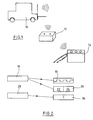
- FIG. 1 shows an industrial truck 10, a battery unit 12 and an external charger 14, each equipped with a transmitting and receiving unit for a wireless communication network.
- a transmitting and receiving unit is capable of receiving signals in the communication network and transmitting signals over it.
- the wireless communication network can be a conventionally constructed radio network which operates according to a defined standard and in which addressed data packets are exchanged with one another.
- the data command packets may include specific data, control signals and other information stored in the data packets according to a protocol.
- a radio network especially when it is used in a warehouse, the situation arises that the signal sent by an industrial truck 10 is received by a plurality of receivers, for example also by a number of battery units. It is therefore necessary that the truck 10 knows a unique identification number of the battery unit to be addressed. It is also necessary that the charger also knows the unique identification number of the battery unit to be addressed in order to be able to exchange this data for the charging process.
- a message 20 is issued, which inform all located in the transmission range battery units via radio via a power pattern.
- the transmitted message 20 therefore has a sender-identifying portion 22 and a current pulse pattern 18 characterizing portion 24. Further, the current pulse pattern 18 is sent through the power circuits. Only the battery unit connected to the vehicle or to the charger can recognize the current pulse pattern 18 by its current measurement and compare it with the part 24 to the current pulse pattern (step 26).
- the association begins when the truck or its control unit is switched on. It generates a current pulse pattern, which is transmitted via the line of electrical connection of the truck and battery unit to this. With the current pulse pattern, the control unit loads the connected battery unit by the power electronics installed in the truck for at least one drive. The data on the current pulse pattern are already sent over the communication network with a lead time before the battery unit is charged with the current pulse pattern. The battery unit is thus able to change to a state in which the current and / or voltage values occurring at the battery unit can be evaluated for comparison with the current pulse pattern.
- current pulse pattern as used to describe the present invention is not necessarily limited to a pattern of current values. It is also entirely conceivable that as a transmitted current pulse pattern, phase information or voltage values on the battery unit are also used partially or exclusively.
- the pattern is preferably understood as a time sequence of signals, but if it is possible to define spatial patterns through a plurality of terminals of the battery unit, this is also included in the term current pulse pattern.
Abstract
Description
Die vorliegende Erfindung betrifft ein Verfahren zum Datenaustausch zwischen einer Batterieeinheit und einer Steuereinheit eines elektrisch mit der Batterieeinheit verbundenen Flurförderzeugs oder eines Ladegeräts.The present invention relates to a method for exchanging data between a battery unit and a control unit of an industrial truck or a charger electrically connected to the battery unit.
Aus
Für ein effektives Fuhrparkmanagement mit einer Vielzahl von Flurförderzeugen, Batterien und Ladegeräten besteht das Bedürfnis, eine effektive Überwachung der Systembestandteile zu realisieren. Eine besondere Schwierigkeit bereitet hierbei, dass die Komponenten des Systems wechselseitig miteinander kombiniert werden können, es kann also beispielsweise eine Batterie in unterschiedlichen Flurförderzeugen eingesetzt und durch unterschiedliche Batterieladegeräte wieder aufgeladen werden. Um einen Datenaustausch zwischen diesen Komponenten zu gewährleisten ist es daher erforderlich, dass die Komponenten, die in elektrischer Verbindung miteinander stehen, auch kommunikationstechnisch einander zugeordnet werden können. Dieser Vorgang wird in Kommunikationsnetzwerken auch als Assoziierung bezeichnet.For an effective fleet management with a large number of industrial trucks, batteries and chargers there is a need to realize an effective monitoring of the system components. A particular difficulty here is that the components of the system can be mutually combined, so it can for example be a battery used in different trucks and recharged by different battery chargers. To ensure a data exchange between these components, it is therefore necessary that the components that are in electrical communication with each other, can also be associated with each other communication technology. This process is referred to as communication in communication networks.
Der Erfindung liegt die Aufgabe zu Grunde, ein Verfahren zum Datenaustausch zwischen einer Batterieeinheit und einer Steuereinheit eines elektrisch mit der Batterieeinheit verbundenen Flurförderzeugs oder eines Ladegeräts bereitzustellen, das mit einfachen Mitteln eine eindeutige Identifizierung der elektrisch an die Batterieeinheit angeschlossenen Komponenten erlaubt.The invention is based on the object to provide a method for exchanging data between a battery unit and a control unit of an electrically connected to the battery unit truck or a charger that allows simple means a unique identification of the electrically connected to the battery unit components.
Erfindungsgemäß wird die Aufgabe durch ein Verfahren mit den Merkmalen aus Anspruch 1 gelöst. Vorteilhafte Ausgestaltungen bilden die Gegenstände der Unteransprüche.According to the invention the object is achieved by a method having the features of claim 1. Advantageous embodiments form the subject of the dependent claims.
Das erfindungsgemäße Verfahren dient zum Datenaustausch zwischen einer Batterieeinheit und einer Steuereinheit eines elektrisch mit der Batterieeinheit verbundenen Flurförderzeugs oder Ladegeräts. Sowohl Flurförderzeug als auch Ladegerät sind jeweils mit einer Steuereinheit ausgestattet, die über ein Kommunikationsnetzwerk ein Assoziierungssignal absetzen kann.The inventive method is used for data exchange between a battery unit and a control unit of an electrically connected to the battery unit truck or charger. Both the truck and the charger are each equipped with a control unit that can issue an association signal via a communication network.
Ferner legt die Steuereinheit über die elektrische Verbindung ein Stromimpulsmuster an die Batterieeinheit an. Erfindungsgemäß trägt das Assoziierungssignal eine eindeutige Identifikationsnummer derjenigen Steuereinheit, die das Assoziierungssignal absetzt. Das Assoziierungssignal beinhaltet eine Datenfolge, die das Stromimpulsmuster eindeutig kennzeichnet. Die Batterieeinheit vergleicht die Datenfolge zu dem Stromimpulsmuster aus dem empfangenen Assoziierungssignal mit einem gemessenen elektrischen Impulsmuster. In dem Fall, dass das gemessene elektrische Stromimpulsmuster mit der Datenfolge zu dem Stromimpulsmuster übereinstimmt, setzt die Batterieeinheit eine Assoziierungsantwort ab. Die Assoziierungsantwort wird über das Kommunikationsnetzwerk an die durch die Identifikationsnummer aus dem Assoziierungssignal gekennzeichnete Steuereinheit adressiert. Durch das erfindungsgemäße Verfahren kann sichergestellt werden, dass die Batterieeinheit eindeutig dem Flurförderzeug oder dem Ladegerät zugeordnet wird, das elektrisch leitend mit der Batterieeinheit verbunden ist. Hierdurch wird ausgeschlossen, dass in dem Kommunikationsnetzwerk Daten zwischen der Batterieeinheit und einem falschen Flurförderzeug oder einem falschen Ladegerät ausgetauscht werden. Als besonders vorteilhaft hat sich hierbei auch herausgestellt, dass die Zuordnung der Batterieeinheit zu einem Gerät stets nur dann erfolgen kann, wenn eine intakte elektrische Verbindung vorliegt.Furthermore, the control unit applies a current pulse pattern to the battery unit via the electrical connection. According to the invention, the association signal carries a unique identification number of the control unit which issues the association signal. The association signal includes a data string that uniquely identifies the current pulse pattern. The battery unit compares the data sequence to the current pulse pattern from the received association signal with a measured electrical pulse pattern. In the case that the measured electric current pulse pattern matches the data sequence to the current pulse pattern, the battery unit suspends an association response. The association response will addressed via the communication network to the designated by the identification number from the association signal control unit. The inventive method can ensure that the battery unit is clearly assigned to the truck or the charger, which is electrically connected to the battery unit. This excludes that in the communication network data between the battery unit and a wrong truck or a wrong charger are replaced. It has also been found to be particularly advantageous here that the assignment of the battery unit to a device can always only take place if there is an intact electrical connection.
In einer bevorzugten Ausgestaltung enthält die Assoziierungsantwort der Batterieeinheit eine eindeutige Identifikationsnummer. Auf diese Weise wird für einen späteren Datenaustausch zwischen der Batterieeinheit und dem elektrisch an die Batterieeinheit angeschlossenen Flurförderzeug oder Ladegerät eine gerichtete Kommunikation über das Kommunikationsnetzwerk möglich. Gerichtete Kommunikation in dem Kommunikationsnetzwerk bezeichnet hierbei einen Datenaustausch, bei dem der Empfänger der Daten durch eine Identifikationsnummer eindeutig gekennzeichnet ist. Zum Datenaustausch in dem Kommunikationsnetzwerk verwendet die Batterieeinheit also stets die eindeutige Identifikationsnummer aus dem Assoziierungssignal, während das Flurförderzeug oder das Ladegerät ihrerseits stets die eindeutige Identifikationsnummer der Batterieeinheit aus der Assoziierungsantwort verwenden.In a preferred embodiment, the association response of the battery unit includes a unique identification number. In this way, a directed communication via the communication network is possible for a later data exchange between the battery unit and the truck or charger connected electrically to the battery unit. Directed communication in the communication network in this case denotes a data exchange in which the recipient of the data is uniquely identified by an identification number. For data exchange in the communication network, the battery unit thus always uses the unique identification number from the association signal, while the truck or the charger in turn always use the unique identification number of the battery unit from the association response.
In einer möglichen Ausgestaltung löst die Steuereinheit des Flurförderzeugs nach Einschalten ein Assoziierungssignal für die elektrisch angeschlossene Batterieeinheit aus. Zweckmäßigerweise kann das Flurförderzeug erst vollständig in Betrieb genommen werden, wenn eine Assoziierungsantwort vorliegt und der Vorgang der Zuordnung zu der Batterieeinheit abgeschlossen ist.In one possible embodiment, the control unit of the truck triggers after switching on an association signal for the electrically connected battery unit. Conveniently, the truck can only be fully put into operation if an association response is present and the process of assignment to the battery unit is completed.
In einer ebenfalls bevorzugten Ausgestaltung wird vor oder mit Beginn des Ladevorgangs in der Steuereinheit des Ladegeräts ein Assoziierungssignal für die angeschlossene Batterieeinheit ausgelöst. Der vollständige Ladevorgang kann erst dann eingeleitet werden, wenn die Assoziierungsantwort vorliegt und die Zuordnung zwischen Ladegerät und Batterieeinheit erfolgt ist.In a likewise preferred embodiment, an association signal for the connected battery unit is triggered before or at the beginning of the charging process in the control unit of the charger. The complete charging process can only be initiated if the association response is present and the assignment between the charger and the battery unit has been made.
Das an die Batterieeinheit angelegte Stromimpulsmuster des Ladegeräts wird bevorzugt als Ladestrom und/oder als Entladestrom an die Batterieeinheit angelegt. Das Stromimpulsmuster des Flurförderzeugs wird zweckmäßigerweise über eine Leistungselektronik des Flurförderzeugs an die Batterieeinheit angelegt. In den beiden Ausgestaltungen misst die Batterie das aufgeprägte Stromimpulsmuster, um auf das empfangene Assoziierungssignal antworten zu können.The current pulse pattern of the charging device applied to the battery unit is preferably applied to the battery unit as a charging current and / or as a discharging current. The current pulse pattern of the truck is suitably applied via a power electronics of the truck to the battery unit. In the two embodiments, the battery measures the impressed current pulse pattern to respond to the received association signal.
Bei elektrisch betriebenen Flurförderzeugen gibt es Fahrzeugausgestaltungen, bei denen die Batterieeinheit für den Ladevorgang nicht von dem Flurförderzeug getrennt wird, sondern elektrisch mit dem Flurförderzeug und dessen Leistungselektronik verbunden bleibt. In einer Ausgestaltung des erfindungsgemäßen Verfahrens ist daher vorgesehen, dass, wenn die Batterieeinheit elektrisch an das Flurförderzeug und das Ladegerät angeschlossen ist, in der Assoziierungsantwort an das Flurförderzeug auch die eindeutige Identifikationsnummer des angeschlossenen Ladegeräts und in der Assoziierungsantwort an das Ladegerät auch die eindeutige Identifikationsnummer des Flurförderzeugs enthalten ist. Auf diese Weise besteht zusätzlich die Möglichkeit, dass das Flurförderzeug und das Ladegerät Daten direkt über das Kommunikationsnetzwerk miteinander austauschen können.In electrically operated trucks there are vehicle designs in which the battery unit for the charging process is not separated from the truck, but remains electrically connected to the truck and its power electronics. In one embodiment of the method according to the invention is therefore provided that, when the battery unit is electrically connected to the truck and the charger, in the Association response to the truck and the unique identification number of the connected charger and in the association response to the charger and the unique identification number of the truck is included. In this way, there is also the possibility that the truck and the charger can exchange data directly via the communication network.
In einer bevorzugten Ausgestaltung der Erfindung gemäß dem Verfahren werden über das Kommunikationsnetzwerk Daten zur Be- und Entladung der Batterieeinheit ausgetauscht. Anhand dieser Daten ist es möglich, bei späteren Be- und Entladevorgängen der Batterie die Vorgeschichte zu berücksichtigen und die Batterien in schonender Weise einzusetzen.In a preferred embodiment of the invention according to the method, data for loading and unloading the battery unit are exchanged via the communication network. On the basis of these data, it is possible to take into account the history of the batteries during later loading and unloading processes and to use the batteries in a gentle manner.
In einer besonders bevorzugten Ausgestaltung ist das Kommunikationsnetzwerk als ein Funknetz ausgebildet. Die Anwendung eines Funknetzes bittet den Vorteil, dass das Netzwerk sich beliebig an die Erfordernisse des konkreten Einsatzes anpassen kann. Auch ist die Verwendung eines Funknetzwerks besonders kostengünstig, da hier auf Standardkomponenten für ein Funknetzwerk zurückgegriffen werden kann.In a particularly preferred embodiment, the communication network is designed as a radio network. The application of a radio network asks the advantage that the network can be adapted to the requirements of the specific application. The use of a wireless network is also particularly cost-effective, since standard components for a radio network can be used here.
In der zweckmäßigen Ausgestaltung sendet die Steuereinheit des Flurförderzeugs oder des Ladegeräts ein Trennsignal für die zugeordnete Batterieeinheit, wenn die elektrische Verbindung zur Batterieeinheit getrennt wird. Um den Trennungsvorgang auch kommunikationstechnisch abzuschließen, sendet die Batterieeinheit nachfolgend eine Trennantwort an die ihr zugeordnete Steuereinheit.In the preferred embodiment, the control unit of the truck or the charger sends a disconnect signal for the associated battery unit when the electrical connection to the battery unit is disconnected. In order to complete the separation process also communication technology, the battery unit sends a separation response below to its associated control unit.
Bevorzugt wird das Stromimpulsmuster zufällig von der Steuereinheit generiert.Preferably, the current pulse pattern is randomly generated by the control unit.
Das erfindungsgemäße Verfahren wird nachfolgend an einem Beispiel näher erläutert. Es zeigt:
- Fig. 1
- ein Flurförderzeug, eine Batterieeinheit und ein externes Ladegerät in einer schematischen Ansicht, und
- Fig. 2
- ein schematisches Ablaufdiagramm zur Assoziierung einer Batterie einheit in einem Funknetzwerk.
- Fig. 1
- an industrial truck, a battery unit and an external charger in a schematic view, and
- Fig. 2
- a schematic flow diagram for the association of a battery unit in a radio network.
In
Ist der Vergleich erfolgreich und zeigt an, dass das angelegte Stromimpulsmuster und das durch den Teil 24 gekennzeichnete Stromimpulsmuster übereinstimmen, so wird eine Assoziierungsantwort an den Absender des Assoziierungssignals 20 geschickt. Der Absender ist durch den Teil 22 der Assoziierungsdaten 20 eindeutig identifiziert.If the comparison is successful and indicates that the applied current pulse pattern and the current pulse pattern indicated by the
In dieser Weise wird eine 1:1 Beziehung zwischen der Steuereinheit des Fahrzeugs zur Batterieeinheit und/oder eine 1:1 Beziehung der Steuereinheit des Ladegeräts und der Batterieeinheit hergestellt. Soll zusätzlich eine 1:1 Beziehung zwischen der Steuereinheit des Fahrzeugs und der Steuereinheit des Ladegeräts hergestellt werden, erfolgt dies über die Batterieeinheit, die dann als Assoziierungsantwort an die eine Steuereinheit jeweils die Identifikationsnummer der anderen Steuereinheit mitsendet. Dieser Schritt setzt natürlich voraus, dass sich zuvor eine Steuereinheit bereits erfolgreich an der Batterieeinheit angemeldet hat.In this way, a 1: 1 relationship between the control unit of the vehicle to the battery unit and / or a 1: 1 relationship of the control unit of the charger and the battery unit is made. Should additionally a 1: 1 Relationship between the control unit of the vehicle and the control unit of the charger are made, this is done via the battery unit, which then sends as an association response to the one control unit in each case the identification number of the other control unit. Of course, this step assumes that a control unit has already successfully logged on to the battery unit.
Im Hinblick auf weitere Assoziierungsanfragen, die als Broadcast-Nachrichten über das Funknetz gesendet werden, kann vorgesehen sein, dass die elektrisch angeschlossene Batterieeinheit weitere Assoziierungsdaten ignoriert. Alternativ kann vorgesehen sein, dass die elektrisch angeschlossene Batterieeinheit auch auf weitere Assoziierungsanfragen reagiert und wie vorstehend beschrieben einen Vergleich der Stromimpulsmuster durchführt.With regard to further association requests, which are sent as broadcast messages over the radio network, it may be provided that the electrically connected battery unit ignores further association data. Alternatively it can be provided that the electrically connected battery unit also responds to further association requests and, as described above, performs a comparison of the current pulse patterns.
Die Assoziierung beginnt mit dem Einschalten des Flurförderzeugs oder seiner Steuereinheit. Es wird ein Stromimpulsmuster generiert, das über die Leitung der elektrischen Verbindung von Flurförderzeug und Batterieeinheit an diese übertragen wird. Mit dem Stromimpulsmuster belastet die Steuereinheit durch die in dem Flurförderzeug installierte Leistungselektronik für mindestens einen Antrieb die angeschlossene Batterieeinheit. Die Daten zu dem Stromimpulsmuster werden mit einem zeitlichen Vorlauf vor der Beaufschlagung der Batterieeinheit mit dem Stromimpulsmuster bereits über das Kommunikationsnetzwerk gesendet. Die Batterieeinheit ist so in der Lage, in einen Zustand zu wechseln, in dem die an der Batterieeinheit auftretenden Strom- und/oder Spannungswerte zum Vergleich mit dem Stromimpulsmuster ausgewertet werden können.The association begins when the truck or its control unit is switched on. It generates a current pulse pattern, which is transmitted via the line of electrical connection of the truck and battery unit to this. With the current pulse pattern, the control unit loads the connected battery unit by the power electronics installed in the truck for at least one drive. The data on the current pulse pattern are already sent over the communication network with a lead time before the battery unit is charged with the current pulse pattern. The battery unit is thus able to change to a state in which the current and / or voltage values occurring at the battery unit can be evaluated for comparison with the current pulse pattern.
Der Begriff Stromimpulsmuster, wie er zur Beschreibung der vorliegenden Erfindung verwendet wurde, ist nicht notwendig auf ein Muster aus Stromwerten beschränkt. Es ist auch durchaus denkbar, dass als übertragenes Stromimpulsmuster auch teilweise oder ausschließlich auf Phaseninformationen oder Spannungswerte an der Batterieeinheit zurückgegriffen wird. Muster wird bei der vorliegenden Erfindung bevorzugt als zeitliche Abfolge von Signalen verstanden, wenn jedoch die Möglichkeit besteht durch mehrere Anschlüsse der Batterieeinheit räumliche Muster zu definieren, so ist dies von dem Begriff Stromimpulsmuster mit umfasst.The term current pulse pattern as used to describe the present invention is not necessarily limited to a pattern of current values. It is also entirely conceivable that as a transmitted current pulse pattern, phase information or voltage values on the battery unit are also used partially or exclusively. In the present invention, the pattern is preferably understood as a time sequence of signals, but if it is possible to define spatial patterns through a plurality of terminals of the battery unit, this is also included in the term current pulse pattern.
Claims (15)
Applications Claiming Priority (1)
| Application Number | Priority Date | Filing Date | Title |
|---|---|---|---|
| DE102008019810A DE102008019810A1 (en) | 2008-04-19 | 2008-04-19 | Data exchange between a battery unit and a control unit |
Publications (3)
| Publication Number | Publication Date |
|---|---|
| EP2110922A2 true EP2110922A2 (en) | 2009-10-21 |
| EP2110922A3 EP2110922A3 (en) | 2011-09-07 |
| EP2110922B1 EP2110922B1 (en) | 2014-06-25 |
Family
ID=40940385
Family Applications (1)
| Application Number | Title | Priority Date | Filing Date |
|---|---|---|---|
| EP09001360.8A Active EP2110922B1 (en) | 2008-04-19 | 2009-01-31 | Data exchange between a battery unit and a control unit |
Country Status (2)
| Country | Link |
|---|---|
| EP (1) | EP2110922B1 (en) |
| DE (1) | DE102008019810A1 (en) |
Cited By (7)
| Publication number | Priority date | Publication date | Assignee | Title |
|---|---|---|---|---|
| WO2011127448A3 (en) * | 2010-04-08 | 2012-02-02 | Qualcomm Incorporated | Energy storage device security |
| EP2645523A1 (en) * | 2012-03-30 | 2013-10-02 | EH Europe GmbH | Battery charging system and method |
| US9013323B2 (en) | 2013-03-15 | 2015-04-21 | Crown Equipment Corporation | Pairing of a battery monitor to a communication device |
| US20150115872A1 (en) * | 2012-03-30 | 2015-04-30 | Eh Europe Gmbh | Power Converter |
| EP2689954A3 (en) * | 2012-07-27 | 2018-01-24 | STILL GmbH | Method for controlling the discharge of a traction battery |
| EP3546420A1 (en) * | 2018-03-28 | 2019-10-02 | Jungheinrich Aktiengesellschaft | Industrial truck with an electrical drive and method for monitoring a traction battery in an industrial truck |
| EP2886388B1 (en) | 2013-12-23 | 2021-06-02 | Linde Material Handling GmbH | Control method for a traction battery |
Families Citing this family (1)
| Publication number | Priority date | Publication date | Assignee | Title |
|---|---|---|---|---|
| DE102012106885A1 (en) | 2012-07-27 | 2014-01-30 | Still Gmbh | Traction battery such as lithium ion battery for mobile working machine e.g. fork lifting truck, has plug connector that is incorporated in coding element of power terminal for identification of type of traction battery |
Citations (3)
| Publication number | Priority date | Publication date | Assignee | Title |
|---|---|---|---|---|
| US4965738A (en) | 1988-05-03 | 1990-10-23 | Anton/Bauer, Inc. | Intelligent battery system |
| DE19922137A1 (en) | 1999-05-12 | 2000-11-16 | Still & Saxby Sarl | Industrial truck with a battery pack |
| EP1840078A1 (en) | 2006-03-29 | 2007-10-03 | Jungheinrich Aktiengesellschaft | Industrial truck with a data bus and a transmitting and receiving unit |
Family Cites Families (3)
| Publication number | Priority date | Publication date | Assignee | Title |
|---|---|---|---|---|
| DE19535294A1 (en) | 1995-09-22 | 1997-03-27 | Heinz Dr Wenzl | Monitoring system for monitoring battery powered vehicle, such as fork-lift truck, and its battery |
| US6417646B1 (en) * | 2001-05-22 | 2002-07-09 | Honeywell International Inc. | Circuit for monitoring cells of a multi-cell battery during charge |
| DE10304284A1 (en) * | 2003-02-03 | 2004-08-19 | Siemens Ag | Identification arrangement for controlling access of electric vehicles to charging stations, wherein an onboard vehicle identification unit is wirelessly connected to the charging station to permit authentication |
-
2008
- 2008-04-19 DE DE102008019810A patent/DE102008019810A1/en not_active Withdrawn
-
2009
- 2009-01-31 EP EP09001360.8A patent/EP2110922B1/en active Active
Patent Citations (3)
| Publication number | Priority date | Publication date | Assignee | Title |
|---|---|---|---|---|
| US4965738A (en) | 1988-05-03 | 1990-10-23 | Anton/Bauer, Inc. | Intelligent battery system |
| DE19922137A1 (en) | 1999-05-12 | 2000-11-16 | Still & Saxby Sarl | Industrial truck with a battery pack |
| EP1840078A1 (en) | 2006-03-29 | 2007-10-03 | Jungheinrich Aktiengesellschaft | Industrial truck with a data bus and a transmitting and receiving unit |
Cited By (14)
| Publication number | Priority date | Publication date | Assignee | Title |
|---|---|---|---|---|
| US8791665B2 (en) | 2010-04-08 | 2014-07-29 | Qualcomm Incorporated | Energy storage device security |
| WO2011127448A3 (en) * | 2010-04-08 | 2012-02-02 | Qualcomm Incorporated | Energy storage device security |
| US20160126755A1 (en) * | 2012-03-30 | 2016-05-05 | Eh Europe Gmbh | Battery Charging System and Method |
| WO2013144160A1 (en) * | 2012-03-30 | 2013-10-03 | Eh Europe Gmbh | Battery charging system and method |
| US20150115872A1 (en) * | 2012-03-30 | 2015-04-30 | Eh Europe Gmbh | Power Converter |
| EP2645523A1 (en) * | 2012-03-30 | 2013-10-02 | EH Europe GmbH | Battery charging system and method |
| EP2689954A3 (en) * | 2012-07-27 | 2018-01-24 | STILL GmbH | Method for controlling the discharge of a traction battery |
| US9013323B2 (en) | 2013-03-15 | 2015-04-21 | Crown Equipment Corporation | Pairing of a battery monitor to a communication device |
| US9699818B2 (en) | 2013-03-15 | 2017-07-04 | Crown Equipment Corporation | Pairing of a battery monitor to a communication device |
| EP3225455A1 (en) * | 2013-03-15 | 2017-10-04 | Crown Equipment Corporation | Pairing of a battery monitor to a communication device, by messages encoded in battery current |
| CN107682847A (en) * | 2013-03-15 | 2018-02-09 | 克朗设备公司 | The pairing of battery monitor and communication equipment is carried out by the message encoded in battery current |
| KR20200119899A (en) * | 2013-03-15 | 2020-10-20 | 크라운 이큅먼트 코포레이션 | Pairing of a battery monitor to a communication device, by message encoded in battery current |
| EP2886388B1 (en) | 2013-12-23 | 2021-06-02 | Linde Material Handling GmbH | Control method for a traction battery |
| EP3546420A1 (en) * | 2018-03-28 | 2019-10-02 | Jungheinrich Aktiengesellschaft | Industrial truck with an electrical drive and method for monitoring a traction battery in an industrial truck |
Also Published As
| Publication number | Publication date |
|---|---|
| DE102008019810A1 (en) | 2009-10-22 |
| EP2110922B1 (en) | 2014-06-25 |
| EP2110922A3 (en) | 2011-09-07 |
Similar Documents
| Publication | Publication Date | Title |
|---|---|---|
| EP2110922B1 (en) | Data exchange between a battery unit and a control unit | |
| DE102012000585B4 (en) | Battery arrangement for a motor vehicle | |
| EP3507966B1 (en) | Method for establishing a wireless vehicle network | |
| EP3659234A1 (en) | Method and device for equalising charging states of individual batteries of a battery system | |
| DE102017204727A1 (en) | A method for establishing a communication link, vehicle communication device and charging station communication device | |
| WO2011006775A2 (en) | Method for communicating between an electric vehicle and a charging station for electrically charging at least one energy store of the electric vehicle | |
| EP2517922A2 (en) | Industrial truck with at least one lithium-ion battery | |
| WO2015121065A1 (en) | Safety device for a battery contactor in an electric vehicle | |
| EP3451496A1 (en) | Communication with charging cable of a battery-powered vehicle | |
| DE102012223530B4 (en) | Dynamic line termination of communication buses in battery module monitoring circuits and a method of performing line termination during initialization of the monitoring system | |
| EP2945215B1 (en) | Traction battery | |
| WO2015104204A1 (en) | Method for starting a battery management system | |
| EP3698419A1 (en) | High-voltage battery system and method for operating a high-voltage battery system | |
| DE102014215830A1 (en) | Battery system and method of communication in a battery system | |
| DE102012006247A1 (en) | Device for operating electrochemical energy storage device e.g. lithium ion battery, of battery management system, has cell controllers that are provided with charge compensation device to perform charge balance between storage cells | |
| EP3670246A1 (en) | Charging assembly for industrial trucks | |
| WO2013104394A1 (en) | Battery arrangement for a motor vehicle | |
| DE102010026130B4 (en) | Connection device for connection to an electrical network, vehicle with this and connection method for connection to an electrical network | |
| DE102018004149A1 (en) | High-voltage electrical system and method for determining the isolation value of a high-voltage vehicle electrical system for an electrically operated motor vehicle | |
| DE102005025954A1 (en) | Charging system for motor vehicle batteries, has charge regulator provided for each rechargeable battery circuit and adjusted, so that charging of battery is interrupted when battery achieves full charge | |
| EP2938093A1 (en) | Industrial truck with an automotive control unit | |
| WO2016118998A1 (en) | Method and apparatus for wireless reading and writing of parameters of electrically powered devices | |
| DE102019135392A1 (en) | Operating method and communication circuit for configuring an energy transfer between a charger and a charging station | |
| EP4046255A1 (en) | Passive supplementary module for rechargeable batteries, rechargeable battery comprising such a passive supplementary module and method for supplying power to a passive supplementary module | |
| WO2023061671A1 (en) | Transmission of service information from a charging station to an electric vehicle |
Legal Events
| Date | Code | Title | Description |
|---|---|---|---|
| PUAI | Public reference made under article 153(3) epc to a published international application that has entered the european phase |
Free format text: ORIGINAL CODE: 0009012 |
|
| AK | Designated contracting states |
Kind code of ref document: A2 Designated state(s): AT BE BG CH CY CZ DE DK EE ES FI FR GB GR HR HU IE IS IT LI LT LU LV MC MK MT NL NO PL PT RO SE SI SK TR |
|
| AX | Request for extension of the european patent |
Extension state: AL BA RS |
|
| PUAL | Search report despatched |
Free format text: ORIGINAL CODE: 0009013 |
|
| AK | Designated contracting states |
Kind code of ref document: A3 Designated state(s): AT BE BG CH CY CZ DE DK EE ES FI FR GB GR HR HU IE IS IT LI LT LU LV MC MK MT NL NO PL PT RO SE SI SK TR |
|
| AX | Request for extension of the european patent |
Extension state: AL BA RS |
|
| RIC1 | Information provided on ipc code assigned before grant |
Ipc: B60L 11/18 20060101AFI20110804BHEP Ipc: H02J 7/00 20060101ALI20110804BHEP |
|
| 17P | Request for examination filed |
Effective date: 20110915 |
|
| AKX | Designation fees paid |
Designated state(s): DE FR GB IT SE |
|
| REG | Reference to a national code |
Ref country code: DE Ref legal event code: R079 Ref document number: 502009009551 Country of ref document: DE Free format text: PREVIOUS MAIN CLASS: H02J0007000000 Ipc: B60L0011180000 |
|
| GRAP | Despatch of communication of intention to grant a patent |
Free format text: ORIGINAL CODE: EPIDOSNIGR1 |
|
| RIC1 | Information provided on ipc code assigned before grant |
Ipc: H02J 7/00 20060101ALI20140115BHEP Ipc: B60L 11/18 20060101AFI20140115BHEP |
|
| INTG | Intention to grant announced |
Effective date: 20140207 |
|
| RIN1 | Information on inventor provided before grant (corrected) |
Inventor name: TAUBE, STEPHAN Inventor name: HANSEN, NILS-PETER Inventor name: RAUTMANN, JUERGEN Inventor name: KROEGER, HENNIG |
|
| GRAS | Grant fee paid |
Free format text: ORIGINAL CODE: EPIDOSNIGR3 |
|
| GRAA | (expected) grant |
Free format text: ORIGINAL CODE: 0009210 |
|
| AK | Designated contracting states |
Kind code of ref document: B1 Designated state(s): DE FR GB IT SE |
|
| REG | Reference to a national code |
Ref country code: GB Ref legal event code: FG4D Free format text: NOT ENGLISH |
|
| REG | Reference to a national code |
Ref country code: DE Ref legal event code: R096 Ref document number: 502009009551 Country of ref document: DE Effective date: 20140807 |
|
| REG | Reference to a national code |
Ref country code: SE Ref legal event code: TRGR |
|
| REG | Reference to a national code |
Ref country code: DE Ref legal event code: R097 Ref document number: 502009009551 Country of ref document: DE |
|
| PLBE | No opposition filed within time limit |
Free format text: ORIGINAL CODE: 0009261 |
|
| STAA | Information on the status of an ep patent application or granted ep patent |
Free format text: STATUS: NO OPPOSITION FILED WITHIN TIME LIMIT |
|
| 26N | No opposition filed |
Effective date: 20150326 |
|
| REG | Reference to a national code |
Ref country code: FR Ref legal event code: PLFP Year of fee payment: 8 |
|
| REG | Reference to a national code |
Ref country code: FR Ref legal event code: PLFP Year of fee payment: 9 |
|
| REG | Reference to a national code |
Ref country code: FR Ref legal event code: PLFP Year of fee payment: 10 |
|
| REG | Reference to a national code |
Ref country code: DE Ref legal event code: R079 Ref document number: 502009009551 Country of ref document: DE Free format text: PREVIOUS MAIN CLASS: B60L0011180000 Ipc: B60L0050500000 |
|
| PGFP | Annual fee paid to national office [announced via postgrant information from national office to epo] |
Ref country code: FR Payment date: 20230123 Year of fee payment: 15 |
|
| PGFP | Annual fee paid to national office [announced via postgrant information from national office to epo] |
Ref country code: SE Payment date: 20230123 Year of fee payment: 15 Ref country code: IT Payment date: 20230131 Year of fee payment: 15 Ref country code: GB Payment date: 20230124 Year of fee payment: 15 Ref country code: DE Payment date: 20230119 Year of fee payment: 15 |