EP2111892A2 - Anti-tachycardic heart stimulator - Google Patents
Anti-tachycardic heart stimulator Download PDFInfo
- Publication number
- EP2111892A2 EP2111892A2 EP09156052A EP09156052A EP2111892A2 EP 2111892 A2 EP2111892 A2 EP 2111892A2 EP 09156052 A EP09156052 A EP 09156052A EP 09156052 A EP09156052 A EP 09156052A EP 2111892 A2 EP2111892 A2 EP 2111892A2
- Authority
- EP
- European Patent Office
- Prior art keywords
- ventricular
- atrial
- atp
- therapy
- unit
- Prior art date
- Legal status (The legal status is an assumption and is not a legal conclusion. Google has not performed a legal analysis and makes no representation as to the accuracy of the status listed.)
- Granted
Links
- 230000002861 ventricular Effects 0.000 claims abstract description 72
- 230000001746 atrial effect Effects 0.000 claims abstract description 50
- 230000000638 stimulation Effects 0.000 claims abstract description 48
- 230000004044 response Effects 0.000 claims abstract description 40
- 206010003130 Arrhythmia supraventricular Diseases 0.000 claims abstract description 24
- 230000008602 contraction Effects 0.000 claims abstract description 21
- 238000002560 therapeutic procedure Methods 0.000 claims description 62
- 230000035939 shock Effects 0.000 claims description 27
- 208000001871 Tachycardia Diseases 0.000 claims description 26
- 230000006794 tachycardia Effects 0.000 claims description 19
- 230000000747 cardiac effect Effects 0.000 claims description 18
- 206010047302 ventricular tachycardia Diseases 0.000 claims description 15
- 238000011156 evaluation Methods 0.000 claims description 14
- 238000001514 detection method Methods 0.000 claims description 13
- 206010047281 Ventricular arrhythmia Diseases 0.000 claims description 4
- 210000005242 cardiac chamber Anatomy 0.000 claims description 4
- 210000005245 right atrium Anatomy 0.000 claims description 4
- 208000003734 Supraventricular Tachycardia Diseases 0.000 description 18
- 210000005241 right ventricle Anatomy 0.000 description 9
- 230000033764 rhythmic process Effects 0.000 description 8
- 238000002633 shock therapy Methods 0.000 description 6
- 210000002837 heart atrium Anatomy 0.000 description 5
- 230000006870 function Effects 0.000 description 4
- 210000005240 left ventricle Anatomy 0.000 description 4
- 210000004165 myocardium Anatomy 0.000 description 4
- 206010049447 Tachyarrhythmia Diseases 0.000 description 3
- 206010061592 cardiac fibrillation Diseases 0.000 description 3
- 230000002600 fibrillogenic effect Effects 0.000 description 3
- 206010003658 Atrial Fibrillation Diseases 0.000 description 2
- 230000001133 acceleration Effects 0.000 description 2
- 206010003119 arrhythmia Diseases 0.000 description 2
- 230000005284 excitation Effects 0.000 description 2
- 230000037081 physical activity Effects 0.000 description 2
- 238000013459 approach Methods 0.000 description 1
- 230000008901 benefit Effects 0.000 description 1
- 230000002457 bidirectional effect Effects 0.000 description 1
- 210000004413 cardiac myocyte Anatomy 0.000 description 1
- 238000013194 cardioversion Methods 0.000 description 1
- 230000008859 change Effects 0.000 description 1
- 210000003748 coronary sinus Anatomy 0.000 description 1
- 230000003111 delayed effect Effects 0.000 description 1
- 230000001419 dependent effect Effects 0.000 description 1
- 238000010586 diagram Methods 0.000 description 1
- 210000005003 heart tissue Anatomy 0.000 description 1
- 230000000004 hemodynamic effect Effects 0.000 description 1
- 239000007943 implant Substances 0.000 description 1
- 230000006872 improvement Effects 0.000 description 1
- 230000000977 initiatory effect Effects 0.000 description 1
- 238000007914 intraventricular administration Methods 0.000 description 1
- 230000001788 irregular Effects 0.000 description 1
- 238000000034 method Methods 0.000 description 1
- 230000002107 myocardial effect Effects 0.000 description 1
- 230000007935 neutral effect Effects 0.000 description 1
- 230000008447 perception Effects 0.000 description 1
- 230000000737 periodic effect Effects 0.000 description 1
- 230000001536 pro-arrhythmogenic effect Effects 0.000 description 1
- 230000002035 prolonged effect Effects 0.000 description 1
- 238000005086 pumping Methods 0.000 description 1
- 230000009467 reduction Effects 0.000 description 1
- 230000001629 suppression Effects 0.000 description 1
- 230000001360 synchronised effect Effects 0.000 description 1
- 230000000213 tachycardiac effect Effects 0.000 description 1
- 210000001519 tissue Anatomy 0.000 description 1
- 210000002620 vena cava superior Anatomy 0.000 description 1
- 208000003663 ventricular fibrillation Diseases 0.000 description 1
Images


Classifications
-
- A—HUMAN NECESSITIES
- A61—MEDICAL OR VETERINARY SCIENCE; HYGIENE
- A61N—ELECTROTHERAPY; MAGNETOTHERAPY; RADIATION THERAPY; ULTRASOUND THERAPY
- A61N1/00—Electrotherapy; Circuits therefor
- A61N1/18—Applying electric currents by contact electrodes
- A61N1/32—Applying electric currents by contact electrodes alternating or intermittent currents
- A61N1/36—Applying electric currents by contact electrodes alternating or intermittent currents for stimulation
- A61N1/362—Heart stimulators
- A61N1/3621—Heart stimulators for treating or preventing abnormally high heart rate
- A61N1/3622—Heart stimulators for treating or preventing abnormally high heart rate comprising two or more electrodes co-operating with different heart regions
Definitions
- the invention relates to an implantable cardiac stimulator for the therapy of tachycardia cardiac arrhythmias.
- a heart stimulator is also known as an implantable cardioverter / defibrillator (ICD) and usually also fulfills the function of an implantable cardiac pacemaker.
- ICD implantable cardioverter / defibrillator
- Stimulation and sensing electrodes can be identical to each other and serve alternately to deliver stimulation pulses and to receive myocardial potentials.
- Tachyarrhythmia is a cardiac arrhythmia that results in a higher heart rate than is physiologically appropriate.
- myocardium tissue myocardium
- ventricular tachycardias are differentiated from supra-ventricular tachycardias (SVT), which are both tachyarrhythmias of one or both of the ventricles (right and / or left ventricle). Whilst ventricular tachycardias originate in the atrium and are transmitted by atrioventricular conduction to the respective ventricle, ventricular tachycardias originate in the respective ventricle itself.
- SVT supra-ventricular tachycardias
- ICDs implantable cardioverter defibrillators
- SVT supraventricular therapy
- VT and supraventricular tachycardia are, for example, to assign irregular, fast atrial and ventricular rhythms to a VT, and regular fast rhythms, however, to an SVT, see e.g. B. US 5,686,793 . US 5,891,170 . US 6,748,269 . US 6,889,080 . US 7,174,209 and US 2004/0093037 , In this way, a discrimination (distinction) between VT and SVT occurs before initiating a corresponding therapy.
- the object of the invention is to provide inadequate shock therapies in the case of cardiac rhythms associated with ventricular tachycardia, i. fall into a pre-established VT zone.
- a necessary (adequate) ventricular therapy should not be delayed as much as possible compared to the current algorithms.
- an implantable cardiac stimulator of the type mentioned above which additionally has an evaluation unit, which is connected to the atrial sensing unit and the therapy control unit and designed by the sensing unit before, during and after a delivery of antitachycardic stimulation (ATP) detected Evaluate atrial rhythm pattern events during ventricular ATP with the atrial rhythm pattern immediately prior to ATP, and target the therapy control unit to select subsequent antitachycardia therapy, depending on the outcome of the comparison.
- ATP antitachycardic stimulation
- US 7,149,577 A similar concept, but not based on the analysis of atrial rhythm patterns, is out US 7,149,577 known.
- US 7,149,577 is the analysis of the rhythm before and after a stimulation in the channel described, in which the stimulation itself takes place.
- the analysis of the rhythm is basically done in a different channel than the stimulated one (especially in the atrium with ventricular ATP).
- the underlying hypothesis is that with simultaneous rapid rhythm in the atrium and ventricle, the atrial rhythm in an SVT is not due to a ventricular rhythm Stimulation is influenced in its rhythm pattern, but in a "true" VT it is modulated by ventricular stimulation.
- current VT / SVT discrimination algorithms do not differentiate between subsequent therapy (ATP-painless / shock-painful) and do not include the information available during therapy delivery in the treatment decision.
- the evaluation unit thus constitutes a type of second tachycardia discrimination unit.
- the heart stimulator is preferably an antitachycardic stimulator with at least one VT and one VF zone, ie, tachycardiac heart rates up to a marginal rate representing an upper bound of the VT zone are associated with tachycardia and heart rates above that marginal rate, which is simultaneously lower Boundary of the VF zone is assigned to a ventricular fibrillation.
- zone is meant areas of heart rates which in the case of the VT zone are associated with tachycardia and in the case of the VF zone with fibrillation.
- the concept of different zones is known in the art, for example US 5,144,947 or US 2004/0093037 , basically known.
- the heart stimulator is preferably an antitachycardic stimulator with a device for delivering at least one defibrillation shock, i. with a defibrillation shock generator connected to or connected to a defibrillation shock electrode and configured to generate and output a defibrillation shock for defibrillation of at least one ventricle.
- the therapy control unit can hereby be designed to inhibit a defibrillation shock as a function of the ATP response signal, preferably only when the ventricular heart rate is in the VT zone, but not in a VF zone.
- the evaluation unit may be designed to evaluate the atrial rhythm immediately after an ATP and in comparison with the atrial rhythm immediately before the ATP.
- the solution according to the invention has the advantage that the specificity of the VT / SVT discrimination can be further increased and thus the number of inadequate shock therapies is reduced. This reduction leads to an increased acceptance of the ICD therapy. This improvement in discrimination leads to no extension of the detection time for the VT detection.
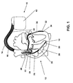
- Fig. 1 shows an implant 10 in the form of a biventricular three-chamber pacemaker and cardioverter / defibrillator (ICD).
- ICD cardioverter / defibrillator
- the right atrial electrode lead 14 has a right atrial tip electrode 22 at its distal end and a right atrial ring electrode 24 a short distance away.
- the right ventricular lead 16 carries a right ventricular tip electrode 18 at its distal end and a right ventricular lead a little further away Ring electrode 20.
- a left ventricular tip electrode 34 and a little away from a left ventricular ring electrode 32 is attached. These electrodes are used to record electrical potentials in the respective heart chamber and the delivery of stimulation pulses to the respective heart chamber in normal pacemaker operation. This need not be explained at this point.
- the right-ventricular electrode lead 16 also carries a right ventricular right-ventricular shock coil 38 in the implanted state as a defibrillation electrode and a second shock coil 40 in the implanted state in the superior vena cava.
- a left-ventricular shock coil 36 is also attached to the left ventricular electrode lead 30. If needed, the shock coils serve as defibrillation electrodes for delivery of defibrillation shocks. Again, this need not be explained in detail here.
- FIG. 2 the main components of the heart stimulator 10 are shown.
- the electrical connections for the various electrodes 18, 20, 24, 22, 32, 34, 36, 38 and 40 are shown.
- Shock electrodes 38 and 40 and 36 are each connected to a right ventricular shock pulse generator 50 and SVC shock generator 52, respectively.
- Both shock generators 50 and 52 are connected to a pacing control unit 54 that drives the two shock pulse generators 50 and 52 as needed to generate and deliver a defibrillation shock.
- connection for the right-ventricular tip electrode RV tip and the connection for the right-ventricular ring electrode RV ring are each connected both to a right-ventricular stimulation unit 56 and to a right-ventricular sensing unit 58. Both the right ventricular pacing unit 56 and the right ventricular sensing unit 58 are each connected to the pacing control unit 54.
- the right-ventricular stimulation unit 56 is designed to generate a right-ventricular stimulation pulse in response to a control signal of the stimulation control unit 54, and subsequently to deliver the right-ventricular tip electrode RV tip for the right-ventricular ring electrode RV ring.
- the housing 42 of the heart stimulator 10 it is also possible for the housing 42 of the heart stimulator 10 to form a neutral electrode and the right-ventricular stimulation unit 56 to form the connection for the right-ventricular ring electrode RV Tip and the housing 42 is connected as another electrode for delivering a stimulation pulse.
- a right ventricular stimulation pulse differs from a defibrillation shock in that the stimulation pulse has a much lower pulse strength so that it does not excite the full heart tissue (myocardium) of a ventricle like a defibrillation shock at one go, but only the heart muscle cells in the immediate vicinity of the right ventricular tip electrode RV Tip 18. This excitation then spreads through natural conduction across the entire right ventricle 28, thus providing a stimulated contraction of the right ventricle 28.
- the right-ventricular sensing unit 58 is designed to initially amplify and filter electrical potential applied to the terminal for the right-ventricular ring electrode RV ring and the right-ventricular tip electrode RV Tip by means of an input amplifier. Furthermore, the right-ventricular sensing unit 58 is designed to evaluate the course of the electrical signals applied to its inputs in such a way that the right-ventricular sensing unit 58 automatically generates a natural (intrinsic), ie. H. automatic contraction of the right ventricle 28 detected. This can be done, for example, by comparing the course of the signal present at the inputs of the right-ventricular sensing unit 58 with a threshold value.
- the largest amplitude of the signal in the form of the so-called R-wave is indicative of a natural contraction of the right ventricle 28, which can be detected by threshold comparison.
- the right ventricular sensing unit 58 then outputs a corresponding output signal indicative of natural contraction of the right ventricle 28 to the pacing control unit 54.
- connection for the right atrial tip electrode RA Tip and the connection for the right atrial ring electrode RA ring are connected both to a right atrial stimulation unit 60 and to a right atrial sensing unit 62, each of which in turn is connected to the stimulation control unit 54.
- the right atrial stimulation unit 60 is designed to generate stimulation pulses whose strength is sufficient to excite the right atrial myocardium.
- the right-atrial stimulation pulses may have a different pulse strength than the right-ventricular stimulation pulses.
- the right-atrial sensing unit 62 is designed to detect a so-called P-wave from the profile of the differential signal applied to its inputs, which characterizes a natural (intrinsic) contraction of the right atrium 26. If the right atrial sensing unit 62 detects a corresponding P-wave, it generates an output signal and passes it on to the stimulation control unit 54, which identifies a natural contraction of the right atrium 26.
- left ventricle tip LV terminal LV Tip and the left ventricular ring LV ring terminal LV are also connected to a left ventricular pacing unit 64 and a left ventricular sensing unit 66.
- the left ventricular pacing unit 64 and the left ventricular sensing unit 66 are also connected to the pacing control unit 54. Both function similarly to the previously described stimulation units 56 and 60 and sensing units 58 and 62.
- an acceleration sensor 72 is connected to the stimulation control unit 54 and integrated into the housing 42 of the heart stimulator 10.
- the acceleration sensor 72 is designed to detect a movement signal dependent on the physical activity of a patient and to output a corresponding first accelerometer output signal, which indicates the physical activity of the patient, to the stimulation control unit 54. This allows the pacing control unit 54 to adjust the timing of the pacing pulses to the needs of the patient (hemodynamic needs).
- the heart stimulator 10 comprises a memory unit 80, which is connected to the stimulation control unit 54 and allows signals generated or evaluated by the stimulation control unit 54 to be stored.
- the memory unit 80 allows control programs for the stimulation control unit 54 to be stored in changeable form.
- the stimulation control unit 54 is connected to a timer 82.
- the memory unit 80 is connected to a telemetry unit 84 which allows data stored in the memory unit 80 to be wirelessly transmitted to an external device or to transmit programming commands from the external device to the heart stimulator 10 and stored in the memory unit 80.
- FIG. 3 shows the relevant to the invention components of the heart stimulator 10, namely the right atrial sensing unit 62, the right ventricular sensing unit 58 and the Stimulation control unit 54 in a detailed representation, this unit, in particular the stimulation control unit 54, even more components than those in FIG. 3 have shown or may have.
- the right-atrial sensing unit 62 and the right ventricle sensing unit 54 are each connected to a connection 110 for an atrial and a ventricular electrode and each have a blanking stage 120 and an amplifier 130 each, which are respectively connected in series to the respective electrode terminal 110.
- the respective blanking stage 120 serves in a known manner for the suppression of stimulation artifacts after delivery of a stimulation pulse.
- the intracardiac signals derived by means of the atrial or ventricular electrode are first amplified.
- the respective amplifier 130 is followed in each case by an A / D converter and filter stage 140, which digitizes and filters the signal.
- the A / D converter and filter stage 140 is followed in each case by a comparator 150, which compares the digitized and filtered signal with a threshold value in each case in order to detect P-waves by threshold value comparison in the case of the intra-atrial signal and by threshold value comparisons in the case of the intraventricular signal To detect R-waves.
- the right atrial sensing unit 62 and the right ventricular sensing unit 58 are each capable of producing a right atrial and a right ventricular sense signal, respectively, if there is a contraction of the respective ventricle.
- the P and R-wave synchronous events (sense signals) thus obtained are supplied to the stimulation control unit 54 and evaluated there by an interval measuring unit 160 with regard to the intervals occurring between them.
- These PP, PR, RP and RR intervals thus obtained are applied to a pacing timer 180 for controlling the antibradycardic pacing. Further, this interval information is compared in an interval evaluation unit 170 for discriminating between VT and SVT in terms of their atrial and ventricular rhythm relationships and made available in evaluated form to a detection and therapy control unit 190 for antitachycardiac therapy (ATP, shock).
- ATP antitachycardiac therapy
- the heart stimulator as part of the stimulation control unit 54 additionally has an evaluation unit 200 for tachycardia discrimination, which is connected to the interval measuring unit 160 and the detection and therapy control unit 190 and which is designed to generate an ATP response signal.
- the evaluation unit 200 evaluates the intervals determined in the interval measuring unit 160 immediately before and during an ATP. For this purpose, there is a bidirectional connection between the evaluation unit 200 and the therapy control unit 190.
- the evaluation unit 200 is informed by the therapy control unit 190 about the impending release of ATP and, in turn, influences the therapy control unit 190 with the respectively obtained ATP response signal.
- the evaluation is designed such that by interpolation those atrial intervals are replaced, which were possibly hidden by a cross-blank during ventricular ATP.
- the following illustrations show possible sequences for the therapy drain control by the therapy control unit 190 as a function of the ATP response signal.
- the Figure 4 shows a simple extension of the therapy procedure control by means of the ATP response signal:
- the programmed antitachycardic stimulation is initially delivered and at the same time determines the ATP response signal. If the atrial rhythm is modulated by the ventricular ATP, the ATP follows a programmed ventricular shock therapy after fulfilled VT redetection, otherwise no shock therapy is released despite satisfied redetection since in this case the initial VT classification is in favor of an SVT due to the ATP response signal was corrected.
- FIG. 5 An alternative implementation is in Figure 5 shown here: After initial VT detection, an ATP and simultaneous analysis of the ATP response signal is performed. If a new VT redetection is fulfilled after the ATP, either a ventricular shock therapy is given off depending on the ATP response signal or the VT / SVT discrimination is restarted. Thus, it is possible to ensure a short redetection time between ATP and shock therapy and only in case of "doubtful" VT classification to start a prolonged redetection with extended discrimination criteria (eg extended detection counter).
- extended discrimination criteria eg extended detection counter
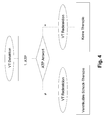
- FIG. 6 Another variant of the implementation shows FIG. 6 :
- an ATP response signal representing an SVT it is decided after redetection whether the atrial arrhythmia is stable or unstable and initiates atrial therapy (RF burst or cardioversion shock) in the case of atrial fibrillation (unstable). On the other hand, if the atrial rhythm is stable, no therapy is delivered (load-induced increase in frequency).
Abstract
Description
Die Erfindung betrifft einen implantierbaren Herzstimulator für die Therapie tachykarder Herzrhythmusstörungen. Ein solcher Herzstimulator ist auch als implantierbarer Cardioverter/Defibrillator (ICD) bekannt und erfüllt in der Regel auch die Funktion eines implantierbaren Herzschrittmachers.The invention relates to an implantable cardiac stimulator for the therapy of tachycardia cardiac arrhythmias. Such a heart stimulator is also known as an implantable cardioverter / defibrillator (ICD) and usually also fulfills the function of an implantable cardiac pacemaker.
Der hier betroffene implantierbare Herzstimulator umfasst:
- eine Kammerstimulationseinheit, die mit einer linksventrikulären oder einer rechtsventrikulären Stimulationselektrode verbunden oder zu verbinden und ausgebildet ist, Kammerstimulationsimpulse zur Stimulation eines Ventrikels eines Herzens zu generieren und abzugeben,
- eine ventrikuläre Sensingeinheit, die ausgebildet ist, eine jeweilige Kammerkontraktion zu erfassen und im Falle einer detektierten Kammerkontraktion ein ventrikuläres Sensingsignal auszugeben,
- eine atriale Sensingeinheit, die ausgebildet ist, eine Vorhofkontraktion zu erfassen und im Falle einer detektierten Vorhofkontraktion ein jeweiliges atriales Ereignis anzeigendes atriales Sensingsignal auszugeben,
- eine Tachykardieerfassungseinheit, die wenigstens mit einer ventrikulären Sensingeinheit verbunden und ausgebildet ist, eine Tachykardie zu erfassen und als ventrikuläre Tachykardie (VT) oder als superventrikuläre Tachykardie zu kategorisieren, und
- eine Therapiesteuereinheit, die ausgebildet ist, wenigstens die Kammerstimulationseinheít zur Abgabe einer antitachykarden Stimulation (ATP) anzusteuern.
- a ventricular pacing unit connected or connected to a left ventricular or a right ventricular pacing electrode and configured to generate and deliver ventricular pacing pulses for pacing a ventricle of a heart;
- a ventricular sensing unit configured to detect a respective chamber contraction and to output a ventricular sensing signal in the event of a detected chamber contraction,
- an atrial sensing unit configured to detect atrial contraction and, in the event of a detected atrial contraction, to output a respective atrial sensing indicating atrial sensing signal,
- a tachycardia detection unit connected to at least one ventricular sensing unit and configured to detect tachycardia and categorize it as ventricular tachycardia (VT) or as superventricular tachycardia, and
- a therapy control unit configured to drive at least the ventricular stimulation device to deliver antitachycardic pacing (ATP).
Stimulations- und Sensingelektroden können dabei miteinander identisch sein und abwechselnd zur Abgabe von Stimulationsimpulsen und zur Aufnahme von Myocard-Potentialen dienen.Stimulation and sensing electrodes can be identical to each other and serve alternately to deliver stimulation pulses and to receive myocardial potentials.
Unter einer Tachyarrhythmie versteht man eine Herzrhythmusstörung, die zu einer höheren Herzrate führt, als physiologisch angemessen ist. Man unterscheidet zum einen Tachykardien und Fibrillationen. Während bei einer Tachykardie (Herzflattern) noch eine Kontraktion einer betroffenen Herzkammer erfolgt, zeichnet sich eine Fibrillation (Herzflimmern) dadurch aus, dass die betroffene Herzkammer einer umlaufenden Erregung ausgesetzt ist, bei der sich Teile des Herzmuskelgewebes (Myokards) der Herzkammer bereits wieder entspannen, während andere Teile erst kontrahieren, so dass zu keiner periodischen Kontraktion und Entspannung der Herzkammer mit für das Pumpen erforderlicher Volumenänderung kommt. Innerhalb der Tachykardien werden u.a. ventrikuläre Tachykardien (VT) von superventrikulären Tachykardien (SVT) unterschieden, die beide Tachyarrhythmien einer oder beider Herzkammern (rechter und/oder linker Ventrikel) sind. Während superventrikuläre Tachykardien ihren Ursprung im Atrium haben und durch atrioventrikuläre Reizleitung auf den jeweiligen Ventrikel übergeleitet werden, haben ventrikuläre Tachykardien ihren Ursprung im jeweiligen Ventrikel selbst.Tachyarrhythmia is a cardiac arrhythmia that results in a higher heart rate than is physiologically appropriate. One differentiates between tachycardia and fibrillations. While in a tachycardia (heart flutter) is still a contraction of an affected ventricle, characterized fibrillation (atrial fibrillation) characterized in that the affected heart chamber is exposed to a circulating excitation, in which parts of the myocardium tissue (myocardium) of the ventricle already relax, while other parts first contract so that there is no periodic contraction and relaxation of the ventricle with the volume change required for pumping. Within the tachycardia u.a. ventricular tachycardias (VT) are differentiated from supra-ventricular tachycardias (SVT), which are both tachyarrhythmias of one or both of the ventricles (right and / or left ventricle). Whilst ventricular tachycardias originate in the atrium and are transmitted by atrioventricular conduction to the respective ventricle, ventricular tachycardias originate in the respective ventricle itself.
Derzeit bieten alle Hersteller implantierbarer Cardioverter/Defibrillatoren (ICD) Geräte an, die zur Diskriminierung zwischen ventrikulärer (VT) und supraventrikulärer Therapie (SVT) in der Lage sind. Eine Gemeinsamkeit dieser Geräte ist es immer, dass sie vor einer Therapie einer Tachyarrhythmie den Ursprung der Tachyarrhythmie festzustellen und - abhängig von dessen Ursprung - eine entsprechende Therapie einzuleiten.Currently, all manufacturers of implantable cardioverter defibrillators (ICDs) offer devices that are capable of discriminating between ventricular (VT) and supraventricular therapy (SVT). A common feature of these devices is always that they determine the origin of the tachyarrhythmia and - depending on its origin - to initiate appropriate therapy before a therapy of tachyarrhythmia.
Bekannte Ansätze zur Unterscheidung zwischen ventrikulärer und supraventrikulärer Tachykardie bestehen darin, z.B. unregelmäßige, schnelle atriale und ventrikuläre Rhythmen einer VT zuzuordnen und regelmäßige schnelle Rhythmen hingegen einer SVT, siehe z. B.
Keiner der derzeit verfügbaren Geräte verfügt dabei über eine 100%ige Spezifität, d. h. inadäquate Therapieabgaben sind die Folge. Besonders kritisch sind in diesem Zusammenhang schmerzhafte Schockabgaben anzusehen, da diese die Akzeptanz der ICD-Therapie drastisch verschlechtern.None of the currently available devices has a 100% specificity, ie inadequate therapy fees are the result. Particularly critical in this context painful shocks as they drastically worsen the acceptance of ICD therapy.
Nicht etabliert haben sich sog. "aktive" Diskriminierungsalgorithmen, die mittels gezielter ventrikulärer oder atrialer Stimulation und Beobachtung der jeweils benachbarten Kammer (Atrium oder Ventrikel) das Diskriminierungsergebnis verbessern können. Wesentlicher Nachteil sind hier die mit der Stimulationsphase verbundene Verzögerung der Detektionsentscheidung und das proarrhythmische Potential einer solchen Stimulation im Vorfeld der Detektionsentscheidung.So-called "active" discrimination algorithms, which can improve the discrimination result by means of targeted ventricular or atrial stimulation and observation of the adjacent chamber (atrium or ventricle), have not established themselves. The main disadvantage here is the delay of the detection decision associated with the stimulation phase and the proarrhythmic potential of such a stimulation in the run-up to the detection decision.
Die Aufgabe der Erfindung besteht darin, inadäquate Schocktherapien im Falle von Herzrhythmen, die einer ventrikulären Tachykardie zugeordnet werden, d.h. in eine zuvor festgelegte VT-Zone fallen, zu verhindern. Dabei soll jedoch eine notwendige (adäquate) ventrikuläre Therapie gegenüber den derzeitigen Algorithmen möglichst nicht zusätzlich verzögert werden.The object of the invention is to provide inadequate shock therapies in the case of cardiac rhythms associated with ventricular tachycardia, i. fall into a pre-established VT zone. However, a necessary (adequate) ventricular therapy should not be delayed as much as possible compared to the current algorithms.
Erfindungsgemäß wird die Aufgabe durch einen implantierbaren Herzstimulator der eingangs genannten Art gelöst, der zusätzlich eine Auswerteeinheit aufweist, die mit der atrialen Sensingeinheit und der Therapiesteuereinheit verbunden und ausgebildet ist, von der Sensingeinheit vor, während und nach einer Abgabe einer antitachykarden Stimulation (ATP) erfasste atriale Ereignisse hinsichtlich des atrialen Rhythmusmusters während ventrikulärer ATP mit dem atrialen Rhythmusmuster unmittelbar vor der ATP auszuwerten und die Therapiesteuereinheit in Abhängigkeit des Vergleichsergebnisses zur Auswahl der nachfolgenden antitachykarden Therapie anzusteuern.According to the invention, the object is achieved by an implantable cardiac stimulator of the type mentioned above, which additionally has an evaluation unit, which is connected to the atrial sensing unit and the therapy control unit and designed by the sensing unit before, during and after a delivery of antitachycardic stimulation (ATP) detected Evaluate atrial rhythm pattern events during ventricular ATP with the atrial rhythm pattern immediately prior to ATP, and target the therapy control unit to select subsequent antitachycardia therapy, depending on the outcome of the comparison.
Ein ähnliches Konzept, das jedoch nicht auf die Analyse atrialer Rhythmusmuster abstellt, ist aus
Die dabei zugrundeliegende Hypothese ist die, dass bei gleichzeitig schnellem Rhythmus in Atrium und Ventrikel der atriale Rhythmus bei einer SVT nicht durch eine ventrikuläre Stimulation in seinem Rhythmusmuster beeinflusst wird, bei einer "echten" VT jedoch durch die ventrikuläre Stimulation moduliert wird. Die derzeitigen Algorithmen zur VT/SVT-Diskriminierung unterscheiden hingegen nicht zwischen der nachfolgenden Therapie (ATP-schmerzlos / Schock-schmerzhaft) und beziehen auch nicht die Informationen, die während der Therapieabgabe verfügbar sind, in die Therapieentscheidung mit ein. Die Auswerteeinheit stellt somit eine Art zweite Tachykardiediskriminierungseinheit dar.The underlying hypothesis is that with simultaneous rapid rhythm in the atrium and ventricle, the atrial rhythm in an SVT is not due to a ventricular rhythm Stimulation is influenced in its rhythm pattern, but in a "true" VT it is modulated by ventricular stimulation. On the other hand, current VT / SVT discrimination algorithms do not differentiate between subsequent therapy (ATP-painless / shock-painful) and do not include the information available during therapy delivery in the treatment decision. The evaluation unit thus constitutes a type of second tachycardia discrimination unit.
Zusammengefasst besteht die Erfindung somit in
- a) einem implantierbaren antitachykarden Stimulator
mit wenigstens einer Stimulations- und Wahrnehmungs-Elektrode im rechten Ventrikel des Herzens (RV) oder im linken Ventrikel (LV bzw. CS) und wenigstens einer Elektrode zur Wahrnehmung des atrialen Signals (RA oder LA) und wenigstens einer Defibrillationsschockelektrode, - b) mit einer Vorrichtung zur Wahrnehmung ventrikulärer und atrialer Ereignisse,
- c) mit einer Vorrichtung zur initialen Detektion einer VT einschließlich der Diskriminierung von VT und SVT (kann auch Einkammer sein),
- d) mit einer Vorrichtung zur Abgabe mindestens einer ventrikulären ATP,
- e) mit einer Vorrichtung zur Wahrnehmung atrialer Ereignisse unmittelbar vor und während der ventrikulären ATP,
- f) mit einer Auswerteeinheit zum Vergleich des atrialen Rhythmusmusters während ventrikulärer ATP mit dem atrialen Rhythmusmuster unmittelbar vor der ATP und
- g) mit einer Therapiesteuereinheit, die in Abhängigkeit des Ergebnisses von (f) die nachfolgende antitachykarde Therapie auswählt.
- a) an implantable antitachycardic stimulator
with at least one pacing and sensing electrode in the right ventricle of the heart (RV) or in the left ventricle (LV or CS) and at least one electrode for sensing the atrial signal (RA or LA) and at least one defibrillation shock electrode, - b) with a device for the perception of ventricular and atrial events,
- c) with a device for the initial detection of a VT including the discrimination of VT and SVT (can also be single-chamber),
- d) with a device for delivering at least one ventricular ATP,
- e) with a device for sensing atrial events immediately before and during ventricular ATP,
- f) with an evaluation unit for comparing the atrial rhythm pattern during ventricular ATP with the atrial rhythm pattern immediately before the ATP and
- g) with a therapy control unit that selects the subsequent antitachycardic therapy depending on the result of (f).
Der Herzstimulator ist vorzugsweise ein antitachykarder Stimulator mit mindestens einer VT- und einer VF-Zone, d.h. tachykarde Herzraten bis zur einer Grenzrate, die eine obere Grenze der VT-Zone darstellt, werden einer Tachykardie zugeordnet und Herzraten oberhalb dieser Grenzrate, die gleichzeitig eine untere Grenze der VF-Zone darstellt, werden einer ventrikulären Fibrillation zugeordnet. Mit Zone sind somit Bereiche von Herzraten gemeint, die im Falle der VT-Zone einer Tachykardie und im Falle der VF-Zone einer Fibrillation zugeordnet werden. Das Konzept verschiedener Zonen ist aus dem Stand der Technik, beispielsweise aus
Weiterhin ist der Herzstimulator vorzugsweise ein antitachykarder Stimulator mit einer Vorrichtung zur Abgabe mindestens eines Defibrillationsschocks, d.h. mit einem Defibrillationsschockgenerator, der mit einer Defibrillationsschockelektrode verbunden oder zu verbinden und ausgebildet ist, einen Defibrillationsschock zur Defibrillation wenigstens einer Herzkammer zu generieren und auszugeben.Furthermore, the heart stimulator is preferably an antitachycardic stimulator with a device for delivering at least one defibrillation shock, i. with a defibrillation shock generator connected to or connected to a defibrillation shock electrode and configured to generate and output a defibrillation shock for defibrillation of at least one ventricle.
Die Therapiesteuereinheit kann hierbei ausgebildet sein, einen Defibrillationsschock in Abhängigkeit des ATP-Antwortsignals zu inhibieren, und zwar vorzugsweise nur, wenn die ventrikuläre Herzrate in der VT-Zone, nicht aber in einer VF-Zone liegt.The therapy control unit can hereby be designed to inhibit a defibrillation shock as a function of the ATP response signal, preferably only when the ventricular heart rate is in the VT zone, but not in a VF zone.
Die Auswerteeinheit kann dazu ausgebildet sein, den atrialen Rhythmus unmittelbar nach einer ATP und im Vergleich mit dem atrialen Rhythmus unmittelbar vor der ATP zu bewerten.The evaluation unit may be designed to evaluate the atrial rhythm immediately after an ATP and in comparison with the atrial rhythm immediately before the ATP.
Folgende weitere Varianten einer Therapieablaufsteuerung durch die Therapiesteuereinheit sind vorteilhaft:
- In Abhängigkeit des ATP-Anwortsignals wird die nachfolgende antitachykarde Therapie inhibiert.
- In Abhängigkeit des ATP-Anwortsignals wird die nachfolgende antitachykarde Therapie fortgesetzt.
- In Abhängigkeit des ATP-Anwortsignals wird die nachfolgende antitachykarde ventrikuläre Therapie durch eine atriale antitachykarde Therapie ersetzt.
- In Abhängigkeit des ATP-Anwortsignals wird zunächst eine neue VT/SVT-Klassifikation (Tachykardiediskriminierung) gestartet.
- In Abhängigkeit des ATP-Anwortsignals werden die Parameter der ventrikulären antitachykarden Therapie (ATP) angepasst.
- Depending on the ATP response signal, the subsequent antitachycardic therapy is inhibited.
- Depending on the ATP response signal, the subsequent antitachycardiac therapy is continued.
- Depending on the ATP response signal, the subsequent antitachycardic ventricular therapy is replaced by atrial antitachycardia therapy.
- Depending on the ATP response signal, a new VT / SVT classification (tachycardia discrimination) is started first.
- Depending on the ATP response signal, the parameters of ventricular antitachycardia therapy (ATP) are adjusted.
Die erfindungsgemäße Lösung bietet den Vorteil, dass die Spezifität der VT/SVT-Diskriminierung weiter erhöht werden kann und damit die Zahl der inadäquaten Schocktherapien reduziert wird. Diese Reduzierung führt zu einer gesteigerten Akzeptanz der ICD-Therapie. Diese Diskriminierungsverbesserung führt dabei zur keiner Verlängerung der Detektionszeit für die VT-Detektion.The solution according to the invention has the advantage that the specificity of the VT / SVT discrimination can be further increased and thus the number of inadequate shock therapies is reduced. This reduction leads to an increased acceptance of the ICD therapy. This improvement in discrimination leads to no extension of the detection time for the VT detection.
Die Erfindung soll nun anhand eines Ausführungsbeispiels mit Bezug auf die Figuren näher erläutert werden. Von den Figuren zeigt:
- Fig. 1:
- einen implantierbaren Dreikammer-Kardioverter/Defibrillator als beispielhaften Herzstimulator in Verbindung mit daran angeschlossenen Elektrodenleitungen;
- Fig. 2:
- ein schematisches Blockschaltbild des Herzstimulators aus
Figur 1 ; - Fig. 3:
- einige Komponenten des Herzstimulators in detaillierterer Darstellung;
- Fig. 4:
- eine erste Implementierung einer Therapiesteuerung in Reaktion auf ein ATP-Antwortsignal in Form eines Flussdiagramms;
- Fig. 5:
- eine zweite Implementierung einer Therapiesteuerung in Reaktion auf ein ATP-Antwortsignal in Form eines Flussdiagramms; und
- Fig. 6:
- eine dritte Implementierung einer Therapiesteuerung in Reaktion auf ein ATP-Antwortsignal in Form eines Flussdiagramms.
- Fig. 1:
- a three-chamber implantable cardioverter / defibrillator as an exemplary cardiac stimulator in conjunction with electrode leads connected thereto;
- Fig. 2:
- a schematic block diagram of the heart stimulator
FIG. 1 ; - 3:
- some components of the heart stimulator in more detail;
- 4:
- a first implementation of a therapy control in response to an ATP response signal in the form of a flowchart;
- Fig. 5:
- a second implementation of a therapy control in response to an ATP response signal in the form of a flowchart; and
- Fig. 6:
- a third implementation of a therapy control in response to an ATP response signal in the form of a flowchart.
Die rechtsatriale Elektrodenleitung 14 trägt an ihrem distalen Ende eine rechtsatriale Spitzenelektrode 22 und in geringem Abstand davon eine rechtsatriale Ringelektrode 24. In ähnlicher Weise trägt die rechtsventrikuläre Elektrodenleitung 16 an ihrem distalen Ende eine rechtsventrikuläre Spitzenelektrode 18 und wenig entfernt davon eine rechtsventrikuläre Ringelektrode 20. Auch am distalen Ende der linksventrikulären Elektrodenleitung 30 ist eine linksventrikuläre Spitzenelektrode 34 und wenig entfernt davon eine linksventrikuläre Ringelektrode 32 angebracht. Diese Elektroden dienen der Aufnahme elektrischer Potenziale in der jeweiligen Herzkammer sowie der Abgabe von Stimulationsimpulsen an die jeweilige Herzkammer im normalen Schrittmacherbetrieb. Diese braucht an dieser Stelle nicht mehr erläutert zu werden.The right
Die rechtsventrikuläre Elektrodenleitung 16 trägt außerdem noch eine im implantierten Zustand im rechten Ventrikel angeordnete rechtsventrikuläre Schockwendel 38 als Defibrillationselektrode sowie eine im implantierten Zustand in der Vena cava superior befindliche zweite Schockwendel 40. Auch an der linksventrikulären Elektrodenleitung 30 ist eine linksventrikuläre Schockwendel 36 angebracht. Die Schockwendeln dienen im Bedarfsfall als Defibrillations-Elektroden zur Abgabe von Defibrillationsschocks. Auch dies braucht an dieser Stelle nicht näher erläutert zu werden.The right-
In
Der Anschluss für die rechtsventrikuläre Spitzenelektrode RV Tip sowie der Anschluss für die rechtsventrikuläre Ringelektrode RV Ring sind jeweils sowohl mit einer rechtsventrikulären Stimulationseinheit 56 als auch mit einer rechtsventrikulären Sensingeinheit 58 verbunden. Sowohl die rechtsventrikuläre Stimulationseinheit 56 als auch die rechtsventrikuläre Sensingeinheit 58 sind jeweils mit der Stimulationssteuereinheit 54 verbunden.The connection for the right-ventricular tip electrode RV tip and the connection for the right-ventricular ring electrode RV ring are each connected both to a right-
Die rechtsventrikuläre Stimulationseinheit 56 ist dazu ausgebildet, auf ein Ansteuersignal der Stimulationssteuereinheit 54 hin einen rechtsventrikulären Stimulationsimpuls zu erzeugen und im Anschluss für die rechtsventrikuläre Ringelektrode RV Ring die rechtsventrikuläre Spitzenelektrode RV Tip abzugeben. Alternativ ist es auch möglich, dass das Gehäuse 42 des Herzstimulators 10 eine neutrale Elektrode bildet und die rechtsventrikuläre Stimulationseinheit 56 mit dem Anschluss für die rechtsventrikuläre Ringelektrode RV Tip und dem Gehäuse 42 als andere Elektrode zur Abgabe eines Stimulationsimpulses verbunden ist. Ein rechtsventrikulärer Stimulationsimpuls unterscheidet sich von einem Defibrillationsschock dadurch, dass der Stimulationsimpuls eine wesentlich geringere Impulsstärke besitzt, so dass er nicht wie ein Defibrillationsschock auf einen Schlag das vollständige Herzgewebe (Myokard) einer Herzkammer erregt, sondern nur die Herzmuskelzellen in unmittelbarer Umgebung der rechtsventrikulären Spitzenelektrode RV Tip 18. Diese Erregung breitet sich dann durch natürliche Reizleitung über den gesamten rechten Ventrikel 28 weiter aus und sorgt so für eine stimulierte Kontraktion des rechten Ventrikels 28.The right-
Die rechtsventrikuläre Sensingeinheit 58 ist dazu ausgebildet, an dem Anschluss für die rechtsventrikuläre Ringelektrode RV Ring und die rechtsventrikuläre Tippelektrode RV Tip anliegende elektrische Potentiale zunächst durch einen Eingangsverstärker zu verstärken und zu filtern. Weiterhin ist die rechtsventrikuläre Sensingeinheit 58 ausgebildet, den Verlauf der an ihren Eingängen anliegenden elektrischen Signale derart auszuwerten, dass die rechtsventrikuläre Sensingeinheit 58 selbsttätig eine natürliche (intrinsische), d. h. selbsttätige Kontraktion des rechten Ventrikels 28 detektiert. Dies kann beispielsweise dadurch geschehen, dass der Verlauf des an den Eingängen der rechtsventrikulären Sensingeinheit 58 anliegenden Signals mit einem Schwellwert verglichen wird. Typischerweise ist die größte Amplitude des Signals in Form der sogenannten R-Zacke kennzeichnend für eine natürliche Kontraktion des rechten Ventrikels 28, die durch Schwellwertvergleich detektiert werden kann. Die rechtsventrikuläre Sensingeinheit 58 gibt daraufhin ein entsprechendes, eine natürliche Kontraktion des rechten Ventrikels 28 anzeigendes Ausgangssignal an die Stimulationssteuereinheit 54 aus.The right-
In analoger Weise sind der Anschluss für die rechtsatriale Spitzenelektrode RA Tip und der Anschluss für die rechtsatriale Ringelektrode RA Ring sowohl mit einer rechtsatrialen Stimulationseinheit 60 als auch mit einer rechtsatrialen Sensingeinheit 62 verbunden, die jeweils ihrerseits wiederum mit der Stimulationssteuereinheit 54 verbunden sind. Die rechtsatriale Stimulationseinheit 60 ist dazu ausgebildet, Stimulationsimpulse zu erzeugen, deren Stärke ausreicht, das rechtsatriale Myokard zu erregen. Die rechtsatrialen Stimulationsimpulse können dabei eine andere Impulsstärke besitzen als die rechtsventrikulären Stimulationsimpulse. Die rechtsatriale Sensingeinheit 62 ist ausgebildet, aus dem Verlauf des an ihren Eingängen anliegenden Differenzsignals eine sogenannte P-Welle zu detektieren, die eine natürliche (intrinsische) Kontraktion des rechten Atriums 26 kennzeichnet. Detektiert die rechtsatriale Sensingeinheit 62 eine entsprechende P-Welle, erzeugt sie ein Ausgangssignal und gibt dieses an die Stimulationssteuereinheit 54 weiter, welches eine natürliche Kontraktion des rechten Atriums 26 kennzeichnet.Analogously, the connection for the right atrial tip electrode RA Tip and the connection for the right atrial ring electrode RA ring are connected both to a right atrial stimulation unit 60 and to a right
In gleicher Weise sind auch der Anschluss für die linksventrikuläre Spitzenelektrode LV Tip und der Anschluss für die linksventrikuläre Ringelektrode LV Ring mit einer linksventrikulären Stimulationseinheit 64 und einer linksventrikulären Sensingeinheit 66 verbunden. Die linksventrikuläre Stimulationseinheit 64 und die linksventrikuläre Sensingeinheit 66 sind ebenso mit der Stimulationssteuereinheit 54 verbunden. Beide funktionieren ähnlich wie die bereits beschriebenen Stimulationseinheiten 56 und 60 und Sensingeinheiten 58 und 62.Similarly, the left ventricle tip LV terminal LV Tip and the left ventricular ring LV ring terminal LV are also connected to a left
Als weiterer Bestandteil des Herzstimulators 10 ist ein Beschleunigungssensor 72 mit der Stimulationssteuereinheit 54 verbunden und in das Gehäuse 42 des Herzstimulators 10 integriert. Der Beschleunigungssensor 72 ist dazu ausgebildet, ein von der körperlichen Aktivität eines Patienten abhängiges Bewegungssignal zu erfassen und ein entsprechendes, die körperliche Aktivität des Patienten anzeigendes erstes Akzelerometer-Ausgangssignal an die Stimulationssteuereinheit 54 auszugeben. Dies erlaubt es, dass die Stimulationssteuereinheit 54 das Timing der Stimulationsimpulse an den Bedarf des Patienten (hämodynamischen Bedarf) anpasst.As an additional component of the
Weiterhin umfasst der Herzstimulator 10 eine Speichereinheit 80, die mit der Stimulationssteuereinheit 54 verbunden ist und es erlaubt, von der Stimulationssteuereinheit 54 erzeugte oder ausgewertete Signale zu speichern. Andererseits erlaubt es die Speichereinheit 80, Steuerprogramme für die Stimulationssteuereinheit 54 in veränderbarer Form zu speichern. Des Weiteren ist die Stimulationssteuereinheit 54 mit einem Zeitgeber 82 verbunden.Furthermore, the
Die Speichereinheit 80 ist mit einer Telemetrieeinheit 84 verbunden, die es erlaubt, in der Speichereinheit 80 abgelegte Daten drahtlos an ein externes Gerät zu übertragen oder Programmierbefehle seitens des externen Geräts zu dem Herzstimulator 10 zu übertragen und in der Speichereinheit 80 zu speichern.The
Die so gewonnen P- und R-Wellen synchronen Ereignisse (Sense-Signale) werden der Stimulationssteuereinheit 54 zugeführt und dort von einer Intervallmesseinheit 160 hinsichtlich der zwischen ihnen auftretenden Intervalle ausgewertet. Diese so gewonnenen PP-, PR-, RP- und RR-Intervalle werden einem Schrittmacherzeitgeber 180 zur Steuerung der antibradykarden Stimulation zugeführt. Ferner werden diese Intervallinformationen in einer Intervallauswerteeinheit 170 zur Diskriminierung zwischen VT und SVT hinsichtlich ihrer Verhältnisse bezüglich atrialem und ventrikulärem Rhythmus verglichen und in bewerteter Form einer Detektions- und Therapiesteuereinheit 190 für die antitachykarde Therapie (ATP, Schock) verfügbar gemacht.The P and R-wave synchronous events (sense signals) thus obtained are supplied to the
Erfindungsgemäß weist der Herzstimulator z.B. als Bestandteil der Stimulationssteuereinheit 54 zusätzlich eine Auswerteinheit 200 zur Tachykardiediskriminierung auf, die mit der Intervallmesseinheit 160 und der Detektions- und Therapiesteuereinheit 190 verbunden ist und die ausgebildet ist, ein ATP-Antwortsignal zu erzeugen.According to the invention, for example, the heart stimulator as part of the
Dazu wertet die Auswerteeinheit 200 die in der Intervallmesseinheit 160 bestimmten Intervalle unmittelbar vor- und während einer ATP aus. Zu diesem Zweck besteht eine bidirektionale Verbindung zwischen der Auswerteeinheit 200 und der Therapiesteuereinheit 190. Die Auswerteeinheit 200 wird von der Therapiesteuereinheit 190 über die bevorstehende ATP-Abgabe informiert und beeinflusst mit dem jeweils gewonnen ATP-Antwortsignal wiederum die Therapiesteuereinheit 190. Die Bestimmung des ATP-Antwortsignals erfolgt dabei durch einen Intervall- oder Mustervergleich der atrialen Intervalle vor und während einer ventrikulären ATP. Bleibt dabei der atriale Rhythmus von der ventrikulären ATP unbeeinflusst (=), so wird eine SVT angenommen. Wird der atriale Rhythmus von der ventrikulären ATP moduliert (≠), so wird eine VT bestätigt. Die Bewertung ist dabei derart gestaltet, dass durch Interpolation diejenigen atrialen Intervalle ersetzt werden, die ggf. durch ein Cross-Blank während ventrikulärer ATP ausgeblendet wurden.For this purpose, the
In den nachfolgenden Abbildungen sind mögliche Abläufe für die Therapieablaufsteuerung durch die Therapiesteuereinheit 190 in Abhängigkeit des ATP-Antwortsignals dargestellt.The following illustrations show possible sequences for the therapy drain control by the
Die
Eine alternative Implementierung ist in
Eine weitere Variante der Implementierung zeigt
Anders als in
Claims (15)
gekennzeichnet durch
marked by
Applications Claiming Priority (1)
| Application Number | Priority Date | Filing Date | Title |
|---|---|---|---|
| DE102008020022A DE102008020022A1 (en) | 2008-04-22 | 2008-04-22 | Anti-tachycardia cardiac stimulator |
Publications (3)
| Publication Number | Publication Date |
|---|---|
| EP2111892A2 true EP2111892A2 (en) | 2009-10-28 |
| EP2111892A3 EP2111892A3 (en) | 2012-01-11 |
| EP2111892B1 EP2111892B1 (en) | 2014-04-16 |
Family
ID=40937595
Family Applications (1)
| Application Number | Title | Priority Date | Filing Date |
|---|---|---|---|
| EP09156052.4A Not-in-force EP2111892B1 (en) | 2008-04-22 | 2009-03-24 | Anti-tachycardic heart stimulator |
Country Status (3)
| Country | Link |
|---|---|
| US (1) | US7983752B2 (en) |
| EP (1) | EP2111892B1 (en) |
| DE (1) | DE102008020022A1 (en) |
Families Citing this family (5)
| Publication number | Priority date | Publication date | Assignee | Title |
|---|---|---|---|---|
| US8903490B2 (en) * | 2010-03-03 | 2014-12-02 | Cardiac Pacemakers, Inc. | Methods and systems for recognizing arrhythmias using neural stimulation |
| EP2510975A1 (en) | 2011-04-14 | 2012-10-17 | BIOTRONIK SE & Co. KG | Cardiac stimulator |
| US9238143B2 (en) | 2011-05-10 | 2016-01-19 | Biotronik Se & Co. Kg | Implantable medical device with electrode fault detection |
| US8670825B2 (en) | 2012-07-31 | 2014-03-11 | Pacesetter, Inc. | Method and system for discrimination of VT and SVT arrhythmias |
| EP2826524B1 (en) * | 2013-07-17 | 2015-07-22 | BIOTRONIK SE & Co. KG | Heart therapy device for detecting ventricular tachycardias and fibrillations |
Citations (7)
| Publication number | Priority date | Publication date | Assignee | Title |
|---|---|---|---|---|
| US5144947A (en) | 1990-04-03 | 1992-09-08 | Telectronics Pacing Systems, Inc. | Apparatus and method for antitachycardia pacing in a arrhythmia control systems |
| US5686793A (en) | 1992-01-29 | 1997-11-11 | Fusion Uv Systems, Inc. | Excimer lamp with high pressure fill |
| US5891170A (en) | 1996-06-18 | 1999-04-06 | Ela Medical, S.A. | Method and apparatus for advanced tachyarrhythmia discrimination |
| US20040093037A1 (en) | 2002-09-04 | 2004-05-13 | Christine Henry | Discrimination between ventricular tachycardia and ventricular fibrillation in an active implantable medical device of the defibrillator, cardiovertor and/or antitachycardia pacemaker type |
| US6748269B2 (en) | 2001-10-17 | 2004-06-08 | Cardiac Pacemakers, Inc. | Algorithm for discrimination of 1:1 tachycardias |
| US6889080B2 (en) | 2000-11-27 | 2005-05-03 | Ela Medical S.A. | Discrimination of atrial fibrillations for an active implantable medical device, in particular a defibrillator/cardiovertor |
| US7149577B2 (en) | 2002-12-02 | 2006-12-12 | Medtronic, Inc. | Apparatus and method using ATP return cycle length for arrhythmia discrimination |
Family Cites Families (3)
| Publication number | Priority date | Publication date | Assignee | Title |
|---|---|---|---|---|
| US6978177B1 (en) * | 2000-11-14 | 2005-12-20 | Cardiac Pacemakers, Inc. | Method and apparatus for using atrial discrimination algorithms to determine optimal pacing therapy and therapy timing |
| US8010193B2 (en) * | 2002-11-20 | 2011-08-30 | University Of Pittsburgh-Of The Commonwealth System Of Higher Education | Device and method to discriminate between supraventricular tachycardias and ventricular arrhythmias |
| US7317942B2 (en) * | 2004-05-05 | 2008-01-08 | Medtronic, Inc. | Dynamic discrimination utilizing anti-tachy pacing therapy in an implantable medical device |
-
2008
- 2008-04-22 DE DE102008020022A patent/DE102008020022A1/en not_active Withdrawn
-
2009
- 2009-03-24 EP EP09156052.4A patent/EP2111892B1/en not_active Not-in-force
- 2009-04-20 US US12/426,325 patent/US7983752B2/en not_active Expired - Fee Related
Patent Citations (8)
| Publication number | Priority date | Publication date | Assignee | Title |
|---|---|---|---|---|
| US5144947A (en) | 1990-04-03 | 1992-09-08 | Telectronics Pacing Systems, Inc. | Apparatus and method for antitachycardia pacing in a arrhythmia control systems |
| US5686793A (en) | 1992-01-29 | 1997-11-11 | Fusion Uv Systems, Inc. | Excimer lamp with high pressure fill |
| US5891170A (en) | 1996-06-18 | 1999-04-06 | Ela Medical, S.A. | Method and apparatus for advanced tachyarrhythmia discrimination |
| US6889080B2 (en) | 2000-11-27 | 2005-05-03 | Ela Medical S.A. | Discrimination of atrial fibrillations for an active implantable medical device, in particular a defibrillator/cardiovertor |
| US6748269B2 (en) | 2001-10-17 | 2004-06-08 | Cardiac Pacemakers, Inc. | Algorithm for discrimination of 1:1 tachycardias |
| US7174209B2 (en) | 2001-10-17 | 2007-02-06 | Cardiac Pacemakers, Inc. | Algorithm for discrimination of 1:1 tachycardias |
| US20040093037A1 (en) | 2002-09-04 | 2004-05-13 | Christine Henry | Discrimination between ventricular tachycardia and ventricular fibrillation in an active implantable medical device of the defibrillator, cardiovertor and/or antitachycardia pacemaker type |
| US7149577B2 (en) | 2002-12-02 | 2006-12-12 | Medtronic, Inc. | Apparatus and method using ATP return cycle length for arrhythmia discrimination |
Also Published As
| Publication number | Publication date |
|---|---|
| US7983752B2 (en) | 2011-07-19 |
| US20090264947A1 (en) | 2009-10-22 |
| EP2111892A3 (en) | 2012-01-11 |
| EP2111892B1 (en) | 2014-04-16 |
| DE102008020022A1 (en) | 2009-10-29 |
Similar Documents
| Publication | Publication Date | Title |
|---|---|---|
| EP1016434B1 (en) | Cardiac pacemaker | |
| DE69732553T2 (en) | Pacemaker with improved detection of atrial fibrillation | |
| DE69633957T2 (en) | Implantable device for antitachycardia | |
| EP2353644B1 (en) | Cardioverter/defibrillator and signal processing device for classifying intracardiac signals | |
| EP1762270B1 (en) | Device for determining cardiac parameters | |
| EP1106206B1 (en) | Apparatus for controlling the rate and the pumping action of the heart | |
| EP1510173B1 (en) | Intracardial impedance measuring device | |
| DE60222071T2 (en) | Implantable pacemaker system with calibration for automatic excitation confirmation | |
| DE60020514T2 (en) | Method for distinguishing heart-recorded electrical events and corresponding system | |
| DE60131041T2 (en) | Implantable cardiac device for monitoring the worsening or improvement of heart disease | |
| EP2135640A1 (en) | Electrotherapy device for treating cardiac arrhythmia | |
| EP2111892B1 (en) | Anti-tachycardic heart stimulator | |
| EP2540341B1 (en) | Cardiac stimulator for delivery of cardiac contractility modulation therapy | |
| DE60031640T2 (en) | Device for detecting natural electrical coherence in the heart and administering a therapy based thereon | |
| EP2676697B1 (en) | Dislocation sensor | |
| EP1302158B1 (en) | Device for predicting tachyarrythmias | |
| EP2140910B1 (en) | Heart stimulator for treating cardiac tachyarrhythmias | |
| DE102008002293A1 (en) | Anti-tachycardia cardiac stimulator | |
| EP2181648A2 (en) | Single chamber heart simulator | |
| EP2111893A1 (en) | Ventricular heart stimulator | |
| EP2184009A2 (en) | Single chamber heart simulator | |
| EP2826524B1 (en) | Heart therapy device for detecting ventricular tachycardias and fibrillations | |
| EP1812107B1 (en) | Device for predicting tachyarrhythmias and/or atrial arrhythmias | |
| EP2422843B1 (en) | Implantable electronic therapy device | |
| EP2510975A1 (en) | Cardiac stimulator |
Legal Events
| Date | Code | Title | Description |
|---|---|---|---|
| PUAI | Public reference made under article 153(3) epc to a published international application that has entered the european phase |
Free format text: ORIGINAL CODE: 0009012 |
|
| AK | Designated contracting states |
Kind code of ref document: A2 Designated state(s): AT BE BG CH CY CZ DE DK EE ES FI FR GB GR HR HU IE IS IT LI LT LU LV MC MK MT NL NO PL PT RO SE SI SK TR |
|
| AX | Request for extension of the european patent |
Extension state: AL BA RS |
|
| PUAL | Search report despatched |
Free format text: ORIGINAL CODE: 0009013 |
|
| AK | Designated contracting states |
Kind code of ref document: A3 Designated state(s): AT BE BG CH CY CZ DE DK EE ES FI FR GB GR HR HU IE IS IT LI LT LU LV MC MK MT NL NO PL PT RO SE SI SK TR |
|
| AX | Request for extension of the european patent |
Extension state: AL BA RS |
|
| RIC1 | Information provided on ipc code assigned before grant |
Ipc: A61N 1/362 20060101AFI20111207BHEP |
|
| 17P | Request for examination filed |
Effective date: 20120620 |
|
| AKX | Designation fees paid |
Designated state(s): CH DE FR GB IE LI SE |
|
| GRAP | Despatch of communication of intention to grant a patent |
Free format text: ORIGINAL CODE: EPIDOSNIGR1 |
|
| INTG | Intention to grant announced |
Effective date: 20131121 |
|
| GRAP | Despatch of communication of intention to grant a patent |
Free format text: ORIGINAL CODE: EPIDOSNIGR1 |
|
| GRAS | Grant fee paid |
Free format text: ORIGINAL CODE: EPIDOSNIGR3 |
|
| INTG | Intention to grant announced |
Effective date: 20140211 |
|
| GRAA | (expected) grant |
Free format text: ORIGINAL CODE: 0009210 |
|
| AK | Designated contracting states |
Kind code of ref document: B1 Designated state(s): CH DE FR GB IE LI SE |
|
| REG | Reference to a national code |
Ref country code: GB Ref legal event code: FG4D Free format text: NOT ENGLISH |
|
| REG | Reference to a national code |
Ref country code: CH Ref legal event code: EP |
|
| REG | Reference to a national code |
Ref country code: IE Ref legal event code: FG4D Free format text: LANGUAGE OF EP DOCUMENT: GERMAN |
|
| REG | Reference to a national code |
Ref country code: DE Ref legal event code: R096 Ref document number: 502009009178 Country of ref document: DE Effective date: 20140605 |
|
| PG25 | Lapsed in a contracting state [announced via postgrant information from national office to epo] |
Ref country code: SE Free format text: LAPSE BECAUSE OF FAILURE TO SUBMIT A TRANSLATION OF THE DESCRIPTION OR TO PAY THE FEE WITHIN THE PRESCRIBED TIME-LIMIT Effective date: 20140416 |
|
| REG | Reference to a national code |
Ref country code: DE Ref legal event code: R097 Ref document number: 502009009178 Country of ref document: DE |
|
| PLBE | No opposition filed within time limit |
Free format text: ORIGINAL CODE: 0009261 |
|
| STAA | Information on the status of an ep patent application or granted ep patent |
Free format text: STATUS: NO OPPOSITION FILED WITHIN TIME LIMIT |
|
| 26N | No opposition filed |
Effective date: 20150119 |
|
| REG | Reference to a national code |
Ref country code: DE Ref legal event code: R097 Ref document number: 502009009178 Country of ref document: DE Effective date: 20150119 |
|
| REG | Reference to a national code |
Ref country code: DE Ref legal event code: R082 Ref document number: 502009009178 Country of ref document: DE Ref country code: DE Ref legal event code: R082 Ref document number: 502009009178 Country of ref document: DE Representative=s name: RANDOLL, SOEREN, DIPL.-CHEM. UNIV. DR. RER. NA, DE |
|
| GBPC | Gb: european patent ceased through non-payment of renewal fee |
Effective date: 20150324 |
|
| REG | Reference to a national code |
Ref country code: FR Ref legal event code: ST Effective date: 20151130 |
|
| PG25 | Lapsed in a contracting state [announced via postgrant information from national office to epo] |
Ref country code: GB Free format text: LAPSE BECAUSE OF NON-PAYMENT OF DUE FEES Effective date: 20150324 |
|
| PG25 | Lapsed in a contracting state [announced via postgrant information from national office to epo] |
Ref country code: FR Free format text: LAPSE BECAUSE OF NON-PAYMENT OF DUE FEES Effective date: 20150331 |
|
| REG | Reference to a national code |
Ref country code: DE Ref legal event code: R082 Ref document number: 502009009178 Country of ref document: DE Ref country code: DE Ref legal event code: R081 Ref document number: 502009009178 Country of ref document: DE Owner name: BIOTRONIK SE & CO. KG, DE Free format text: FORMER OWNER: BIOTRONIK CRM PATENT AG, BAAR, CH |
|
| PGFP | Annual fee paid to national office [announced via postgrant information from national office to epo] |
Ref country code: IE Payment date: 20220322 Year of fee payment: 14 Ref country code: DE Payment date: 20220317 Year of fee payment: 14 Ref country code: CH Payment date: 20220324 Year of fee payment: 14 |
|
| REG | Reference to a national code |
Ref country code: DE Ref legal event code: R119 Ref document number: 502009009178 Country of ref document: DE |
|
| REG | Reference to a national code |
Ref country code: CH Ref legal event code: PL |
|
| REG | Reference to a national code |
Ref country code: IE Ref legal event code: MM4A |
|
| PG25 | Lapsed in a contracting state [announced via postgrant information from national office to epo] |
Ref country code: LI Free format text: LAPSE BECAUSE OF NON-PAYMENT OF DUE FEES Effective date: 20230331 Ref country code: IE Free format text: LAPSE BECAUSE OF NON-PAYMENT OF DUE FEES Effective date: 20230324 Ref country code: DE Free format text: LAPSE BECAUSE OF NON-PAYMENT OF DUE FEES Effective date: 20231003 Ref country code: CH Free format text: LAPSE BECAUSE OF NON-PAYMENT OF DUE FEES Effective date: 20230331 |