EP2123225A1 - Endoscope device - Google Patents
Endoscope device Download PDFInfo
- Publication number
- EP2123225A1 EP2123225A1 EP09006717A EP09006717A EP2123225A1 EP 2123225 A1 EP2123225 A1 EP 2123225A1 EP 09006717 A EP09006717 A EP 09006717A EP 09006717 A EP09006717 A EP 09006717A EP 2123225 A1 EP2123225 A1 EP 2123225A1
- Authority
- EP
- European Patent Office
- Prior art keywords
- main body
- insertion part
- observation main
- arm members
- observation
- Prior art date
- Legal status (The legal status is an assumption and is not a legal conclusion. Google has not performed a legal analysis and makes no representation as to the accuracy of the status listed.)
- Granted
Links
- 238000003780 insertion Methods 0.000 claims abstract description 129
- 230000037431 insertion Effects 0.000 claims abstract description 129
- 238000005452 bending Methods 0.000 claims description 48
- 230000008602 contraction Effects 0.000 claims description 6
- 239000000284 extract Substances 0.000 claims description 2
- 230000004048 modification Effects 0.000 description 56
- 238000012986 modification Methods 0.000 description 56
- 238000010276 construction Methods 0.000 description 47
- 238000000034 method Methods 0.000 description 25
- 238000002347 injection Methods 0.000 description 4
- 239000007924 injection Substances 0.000 description 4
- 230000000694 effects Effects 0.000 description 2
- 210000003815 abdominal wall Anatomy 0.000 description 1
- 238000007792 addition Methods 0.000 description 1
- 239000003814 drug Substances 0.000 description 1
- 229940079593 drug Drugs 0.000 description 1
- 239000000243 solution Substances 0.000 description 1
- 238000006467 substitution reaction Methods 0.000 description 1
- XLYOFNOQVPJJNP-UHFFFAOYSA-N water Substances O XLYOFNOQVPJJNP-UHFFFAOYSA-N 0.000 description 1
Images


Classifications
-
- A—HUMAN NECESSITIES
- A61—MEDICAL OR VETERINARY SCIENCE; HYGIENE
- A61B—DIAGNOSIS; SURGERY; IDENTIFICATION
- A61B17/00—Surgical instruments, devices or methods, e.g. tourniquets
- A61B17/00234—Surgical instruments, devices or methods, e.g. tourniquets for minimally invasive surgery
-
- A—HUMAN NECESSITIES
- A61—MEDICAL OR VETERINARY SCIENCE; HYGIENE
- A61B—DIAGNOSIS; SURGERY; IDENTIFICATION
- A61B1/00—Instruments for performing medical examinations of the interior of cavities or tubes of the body by visual or photographical inspection, e.g. endoscopes; Illuminating arrangements therefor
- A61B1/00064—Constructional details of the endoscope body
- A61B1/00071—Insertion part of the endoscope body
- A61B1/0008—Insertion part of the endoscope body characterised by distal tip features
- A61B1/00087—Tools
-
- A—HUMAN NECESSITIES
- A61—MEDICAL OR VETERINARY SCIENCE; HYGIENE
- A61B—DIAGNOSIS; SURGERY; IDENTIFICATION
- A61B1/00—Instruments for performing medical examinations of the interior of cavities or tubes of the body by visual or photographical inspection, e.g. endoscopes; Illuminating arrangements therefor
- A61B1/012—Instruments for performing medical examinations of the interior of cavities or tubes of the body by visual or photographical inspection, e.g. endoscopes; Illuminating arrangements therefor characterised by internal passages or accessories therefor
- A61B1/018—Instruments for performing medical examinations of the interior of cavities or tubes of the body by visual or photographical inspection, e.g. endoscopes; Illuminating arrangements therefor characterised by internal passages or accessories therefor for receiving instruments
Landscapes
- Health & Medical Sciences (AREA)
- Life Sciences & Earth Sciences (AREA)
- Surgery (AREA)
- General Health & Medical Sciences (AREA)
- Public Health (AREA)
- Veterinary Medicine (AREA)
- Nuclear Medicine, Radiotherapy & Molecular Imaging (AREA)
- Animal Behavior & Ethology (AREA)
- Molecular Biology (AREA)
- Engineering & Computer Science (AREA)
- Biomedical Technology (AREA)
- Heart & Thoracic Surgery (AREA)
- Medical Informatics (AREA)
- Biophysics (AREA)
- Radiology & Medical Imaging (AREA)
- Physics & Mathematics (AREA)
- Pathology (AREA)
- Optics & Photonics (AREA)
- Endoscopes (AREA)
- Instruments For Viewing The Inside Of Hollow Bodies (AREA)
Abstract
Description
- The present invention relates to an endoscope device which is inserted into the body cavity and is used together with a device such as a flexible endoscope.
- Conventionally, endoscope devices are used for observing and treating an affected area or the like within the body cavity of the subject. Endoscope devices are known in which an elongated and flexible insertion part which is inserted into the body cavity from the distal side, and an operating part for operating the insertion part are provided so as to connect to each other.
- The distal portion of the insertion part is provided with an observation main body for observing the periphery, and a distal end construction part on the distal end surface of which two arm members into which treatment tools for performing treatment are inserted are provided. A bendable tuber bending part is connected to the proximal side of the distal end construction part, and a flexible tuber part which is connected with an operating part is connected to the proximal side of the bending part. A distal portion of an operating wire inserted into the bending part and the flexible tuber part is fixed to the proximal side of the distal end construction part, and the proximal portion of the operating wire is attached to an angle knob which is provided in the operating part and pulls the operating wire.
- Instrument channels are formed so as to extend from the distal portions of the two arm members to a forceps plug provided in the operating part via the insertion part. By inserting the treatment tools into the instrument channels, treatment can be performed with the distal portions of the treatment tools protruded from the distal ends of the arm members.
- In the endoscope device constituted as above, the insertion part is inserted into the body cavity of the subject while observing the periphery by using the observation main body and bending the bending part by using the angle knob so that the distal portions of the treatment tools do not protrude from the distal ends of the two arm members. Then, the insertion part is fixed so that the two arm members are opposed to the affected area and the distal end portions of the treatment tools are protruded from the distal ends of the arm members to perform treatment.
- However, with the above-described conventionally endoscope devices, since the distance between the observation main body and the proximal ends of the two arm members is short, the proximal portions of the two arm members extensively appear on the field of view via the observation main body. As a result, it is difficult to observe the state of treatment performed by the treatment tools by using the observation main body. When making the distance between the observation main body and the proximal ends of the two arm members large, since the diameter of the insertion part also becomes large, the insertion ability reduces.
- The present invention was devised in view of the above circumstances, and has as an object the provision of an endoscope device in which depression of the insertion ability of the insertion part is prevented and visibility of the distal portions of the arm members when performing treatment is enhanced.
- The present invention relates to an endoscope device comprising: an elongated tubular insertion part; a plurality of arm members which is provided in the distal portion of the insertion part so as to protrude forward and is capable of treatment with a treatment tool inserted thereinto; an observation main body provided in the distal portion of the insertion part so as to freely separate from the insertion part; an energization member which energizes the observation main body disposed within the distal portion of the insertion part toward the direction opposite to the plurality of the arm members in the radial direction of the insertion part; arid a holding mechanism which resists the energization member to hold the observation main body in a state where the observation main body is disposed within the distal portion of the insertion part and is capable of releasing the holding state.
-
-
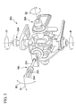
FIG. 1 is an overall view showing an endoscope device according to a first embodiment of the present invention. -
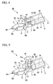
FIG. 2 is an overall view showing a medical treatment endoscope in which the endoscope device according to the first embodiment of the present invention is attached. -
FIG 3 illustrates a view seen from the arrow A inFIG 2 . -
FIG 4 shows an insertion part of the endoscope device according to the first embodiment of the present invention. -
FIG 5 shows a treatment method with the endoscope device according to the first embodiment of the present invention. -
FIG. 6 shows an insertion part of an endoscope device according to a modification example of the first embodiment of the present invention. -
FIG 7 shows a treatment method with the endoscope device according to the modification example of the first embodiment of the present invention. -
FIG. 8 shows an insertion part of an endoscope device according to a second embodiment of the present invention. -
FIG. 9 shows a treatment method with the endoscope device according to the second embodiment of the present invention. -
FIG. 10 shows an insertion part of an endoscope device according to a modification example of the second embodiment of the present invention. -
FIG. 11 shows a treatment method with the endoscope device according to the modification example of the second embodiment of the present invention. -
FIG. 12 shows an insertion part of an endoscope device according to a third embodiment of the present invention. -
FIG 13 a sectional view showing the principal portions of the insertion part of the endoscope device according to the third embodiment of the present invention. -
FIG. 14 shows a treatment method with the endoscope device according to the third embodiment of the present invention. -
FIG 15 shows an insertion part of an endoscope device according to a modification example of the third embodiment of the present invention. -
FIG. 16 shows an insertion part of an endoscope device according to a fourth embodiment of the present invention. -
FIG. 17 shows an insertion part of an endoscope device according to a fifth embodiment of the present invention. -
FIG. 18 is a plan view of the insertion part of the endoscope device according to the fifth embodiment of the present invention. -
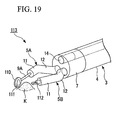
FIG 19 shows an insertion part of an endoscope device according to a sixth embodiment of the present invention. -
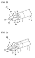
FIG. 20 shows an insertion part of an endoscope device according to a first modification example of the sixth embodiment of the present invention. -
FIG 21 shows an insertion part of an endoscope device according to a second modification example of the sixth embodiment of the present invention. -
FIG 22 shows an insertion part of an endoscope device according to a third modification example of the sixth embodiment of the present invention. -
FIG 23 shows an insertion part of an endoscope device according to a fourth modification example of the sixth embodiment of the present invention. -
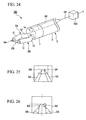
FIG 24 shows an insertion part of an endoscope device according to a seventh embodiment of the present invention. -
FIG 25 is an image of treatment parts before magnification displayed on a monitor according to the seventh embodiment of the present invention. -
FIG 26 is an image of the treatment parts after magnification displayed on the monitor according to the seventh embodiment of the present invention. -
FIG. 27 shows an insertion part of an endoscope device according to an eighth embodiment of the present invention. -
FIG 28 shows a treatment method with the endoscope device according to the eighth embodiment of the present invention. -
FIG 29 shows an insertion part of an endoscope device according to a modification example of the eighth embodiment of the present invention. -
FIG. 30 shows an insertion part of an endoscope device according to another modification example of the eighth embodiment of the present invention. -
FIG 31 shows an insertion part of an endoscope device according to a ninth embodiment of the present invention. -
FIG 32 shows a treatment method with the endoscope device according to the ninth embodiment of the present invention. - Embodiments according to the present invention will now be described in detail below. The basal structures of endoscope devices according to the present invention have been described in
US Patent Application Ser. ,No 11/331,963US Patent Application Ser. , andNo 11/435,183US Patent Application Ser. , and the described contents of which are incorporated in the following description.No 11/652,880 - As shown in
FIG 1 , anendoscope device 1 has anoperating part 2 and atubular insertion part 3 which extends from one end of theoperating part 2 in a unitary manner. Theinsertion part 3 is elongated and has flexibility. Theinsertion part 3 has the same construction as an insertion part described inU.S. Patent Application No. 11/435,183 orU.S. Patent Application No. 11/652,880 . That is, theinsertion part 3 has asheath 4, a distalend construction part 7 which is disposed in the distal portion of thesheath 4, and bendable first andsecond arm members distal end surface 7h of the distalend construction part 7 so as to protrude forward.Instrument channels 6 are formed inside thearm members connection sheath 20 via theinsertion part 3 and operatingpart 2.Treatment tools instrument channels 6 respectively, andtreatment parts treatment tools arm members treatment tools second arm members - A
first bending part 11 and asecond bending part 12 are formed in eacharm member second bending parts third bending part 13 formed in theinsertion part 3. - An observation
main body 14 for observing inside the body is disposed on the outer circumferential surface of the distal portion of the distalend construction part 7 so as to be capable of separating from theinsertion part 3. The observationmain body 14 is held by aholding mechanism 15. - The first and
second arm members sheath 4, as described inU.S. Patent Application No. 11/652,880 . - A
forceps plug 16 is provided in theoperating part 2 at the side surface of the one end portion connecting to theinsertion part 3. The forceps plug 16 communicates with theinstrument channels 6 formed within thesheath 4. By inserting a second treatment tool (not shown) from theforceps plug 16, the second treatment tool can be protruded from the distal end of first orsecond arm member part 2 is further provided with aswitch 17, anangle knob 18, and auniversal cable 19 which is connected to a control device or a monitor (not shown). Theswitch 17 is operated, for example, when feeding air or water, or aspirating through theinstrument channel 6 formed within theinsertion part 3. Theangle knob 18 is used when bending thethird bending part 13 in all directions with respect to the axis. An image observed by the observationmain body 14 is transmitted to the monitor via theuniversal cable 19. - As shown in
FIG 2 , the elongated and flexible connectingsheath 20 is provided so as to extend from the other end portion of the operatingpart 2. Anoperator 25 is provided at the end portion of theconnection sheath 20. - The
operator 25 has a base 26 which fixes theconnection sheath 20. Afirst operating unit 30A and asecond operating unit 30B are attached with respect to thebase 26. Thefirst operating unit 30A has anoperating stick 31A into which anoperating part 10A of thetreatment tool 8A inserted into thefirst arm member 5A is inserted. The operatingpart 10A is supported via theoperating stick 31 A so as to freely advance and retract in the axial direction and to freely lean in all directions about the axis. Thesecond operating unit 30B has anoperating stick 31B into which anoperating part 10B of thetreatment tool 8B inserted into thefirst arm member 5B is inserted. The operatingpart 10B is supported via theoperating stick 31B so as to freely advance and retract in the axial direction and to freely lean in all directions about the axis. - By the known constitution shown in
FIG 3 , when the operator rotates theoperating stick 31A to the direction D1, thefirst rotation mechanism 3 2A rotates to the direction E1. As a result, the first bendingpart 11 of thefirst arm member 5A is bent to the direction F1 as shown inFIG 1 by an operating wire (not shown) wound on thefirst rotation mechanism 32A. When the operator rotates theoperating stick 31A to the direction D2, thesecond rotation mechanism 33A rotates to the direction E2. As a result, the first bendingpart 11 of thefirst arm member 5A is bent to the direction F2 orthogonal to the direction F1 (i.e., the direction orthogonal to the sheet) by an operating wire (not shown) wound on thesecond rotation mechanism 33A. - Although the detailed explanation is omitted, the first bending
part 11 of thesecond arm member 5B is similarly bent when anoperating stick 31B shown inFIG 2 is rotated. - When an operating lever (not shown) is pushed, the
second bending parts 12 of the first andsecond arm members arm members distal end surface 7h of the distalend construction part 7. By pulling and then fixing the operating lever, as shown inFIG 1 , thesecond bending parts 12 are maintained in the curbed shape in a state where the first andsecond arm members - In the present embodiment, a gripping forceps is employed as the
treatment tool 8A and an injection instrument is employed as thetreatment tool 8B. As shown inFIG 3 , the opening/closing operation of the distal portion of this gripping forceps is performed by moving aslider 35A with respect to aring 34A in the axial direction to pull and push an operating wire (not shown) connected to thetreatment part 9A. On the other hand, when injecting by the injection instrument of thetreatment part 9B into the tissue, as shown inFIG 2 , a slider 35 provided in thesecond operating unit 30 B is operated. Though in this embodiment, a gripping forceps and an injection instrument are employed as thetreatment tools - As shown in
FIG. 4 , afirst groove 7a is formed along the axis C1 of theinsertion part 3 on the outer circumferential surface of the distalend construction part 7, and the observationmain body 14 is disposed within thefirst groove 7a. The observationmain body 14 houses a light receiving element such as a lens and a CCD, and connects to anobservation cable 43 which transmits an image obtained by the observationmain body 14 to the monitor. Theobservation cable 43 has a bending tendency and plays a role as an energizing member which energizes the observationmain body 14 disposed in thefirst groove 7a toward the moving direction G1 opposite to the first andsecond arm members insertion part 3. Theobservation cable 43 is guided by a guide hole (not shown) communicating from the distalend construction part 7 of theinsertion part 3 to theoperating part 2. - Here, as shown in
FIG. 4 , the opposite side of the first andsecond arm members insertion part 3 means a symmetrical side with the midpoint P between the positions where the first andsecond arm members distal end surface 7h of the distalend construction part 7, with respect to the axis C1. - A
second groove 7b is formed along the circumferential direction on the outer circumferential surface of the distalend construction part 7, and a curved plate-shaped open/close member 41 is supported by thesecond groove 7b so as to freely move along the circumferential direction of the distalend construction part 7. As shown inFIG 4 , the open/close member 41 is set such that, when moving to one side of thesecond groove 7b, the open/close member 41 resists the energizing force by theobservation cable 43 to hold the observationmain body 14 in a state where the observationmain body 14 is disposed within thefirst groove 7a, and, when moving from the position shown inFIG 4 to the other side of thesecond groove 7b, the holding state of the observationmain body 14 is released. Both end portions of the open/close member 41 are connected to an open/closemember driving wire 44. The open/closemember driving wire 44 is guided by the guide hole (not shown) communicating from the distalend construction part 7 of theinsertion part 3 to theoperating part 2, and is operated by an observation main body operating lever (not shown) provided in theoperating part 2. - The open/
close member 41 and the open/closemember driving wire 44 constitute the above-describedholding mechanism 15. - Method for treating an affected area with the
endoscope device 1 constituted as above is described as follows. - First, the operating lever is pushed such that the first and
second arm members treatment tools operating parts treatment parts treatment parts arm members - Next, the periphery is observed by the observation
main body 14, and theinsertion part 3 is inserted into the body cavity of the subject while bending thefirst bending portions 11 of thearm members second operating units third bending part 13 by using theangle knob 18. - Next, the
insertion part 3 is fixed in a state where the distal portions of the twoarm members treatment tools operating parts treatment parts treatment tools arm members FIG. 4 . By pulling and then fixing the operating lever, thesecond bending parts 12 are fixed in a bending state where the first andsecond arm members - Next, as shown in
FIG 5 , by operating the open/closemember driving wire 44 by using the observation main body operating lever, the open/close member 41 is moved to the other side of thesecond groove 7b to release the holding state of the observationmain body 14. As a result, since theobservation cable 43 energizes the observationmain body 14 disposed in thefirst groove 7a toward the moving direction G1, the observationmain body 14 is moved to a position separating from the distalend construction part 7 while maintaining the posture of the observationmain body 14. - In this state, while observing the affected area with the observation
main body 14, the affected area is grasped by thetreatment part 9A by rotating theoperating stick 31A to bend the first bendingpart 11 of thefirst arm member 5A and by moving theslider 35A. Then, the needle-shapedtreatment part 9B is pricked into the affected area while bending the first bendingpart 11 of thesecond arm member 5B by rotating theoperating stick 31B, and the drug solution or the like (not shown) is injected into the affected area by moving theslider 35B. - When the treatment of the affected area has been finished, in the same manner as when inserting the
insertion part 3 into the body cavity, the operating lever is pushed such that the first andsecond arm members treatment tools operating parts treatment parts treatment parts arm members main body 14 is housed within thesheath 4 by pulling theobservation cable 43 toward the proximal end. After making theinsertion part 3 in this state, theinsertion part 3 is pulled toward the proximal end so as to be pulled out from the body cavity. - As described above, according to the
endoscope device 1 of the present embodiment, the first andsecond arm members distal end surface 7h of the distalend construction part 7, and the observationmain body 14 is disposed within thefirst groove 7a. Therefore, since the outer diameter of theinsertion part 3 including thearm members insertion part 3 when inserting theinsertion part 3 into the body cavity of the subject can be prevented. - Furthermore, since the observation
main body 14 is moved to a position separating from the distalend construction part 7 while maintaining the posture of the observationmain body 14, thetreatment parts second arm members main body 14 is interrupted by the proximal portions of the first andsecond arm members treatment parts - Furthermore, since the distance from the
treatment parts main body 14 can be elongated, the range of view of thetreatment parts main body 14 can be enlarged. As a result, the treatment of the affected area can be securely performed in brief time. - Next, a modification example of the first embodiment of the present invention will be described. Elements the same as those of the first embodiment are denoted by the same reference numerals and the descriptions thereof are omitted, and only different points are described.
- As shown in
FIG. 6 , anendoscope device 55 of the present modification example is provided with a movingmechanism 50 which moves the observationmain body 14. The movingmechanism 50 has a pair oflink members 53 which are symmetrically disposed so as to sandwich the observationmain body 14 therebetween with one end portion of thelink member 53 rotatively supported to the observationmain body 14 by afirst pin 51, and the other end portion of thelink member 53 rotatively supported to theinsertion part 3 by asecond pin 52. - The
second pin 52 is disposed such that the axis of thesecond pin 52 is positioned closer to the axis C1 than the axis of thefirst pin 51. Anobservation cable 54 of the present modification example does not have a bending tendency. - Next, a method for treating an affected area with the
endoscope device 55 constituted as above is described as follows. - The treatment method of the present modification example is basically the same as that of the first embodiment. However, in the present modification example, as shown in
FIG 7 , theobservation cable 54 inserted into a guide hole (not shown) is moved toward the proximal end by pulling theobservation cable 54 toward the proximal end at the operatingpart 2 after thesecond bending parts 12 of the first andsecond arm members main body 14 is moved to a position separating from the distalend construction part 7 by rotating the pair of thelink members 53 around thesecond pin 52. - As described above, according to the
endoscope device 55 of the present modification example, the same effects as those of the first embodiment can be obtained. - Next, a second embodiment of the present invention will be described.
Elements the same as those of the first embodiment and the modification example thereof are denoted by the same reference numerals and the descriptions thereof are omitted, and only different points are described. - As shown in
FIG. 8 , anendoscope device 64 of the present embodiment is provided with an extension/contraction mechanism 60 which moves the observationmain body 14 toward the moving direction G1 opposite to the first andsecond arm members contraction mechanism 60 has atelescopic portion 62 formed by nesting a plurality ofcylindrical members 61 having diameters different from each other such that the entirety of thetelescopic portion 62 freely extends and contracts in the moving direction G1, and anoperating wire 63 which protrudes and retracts thetelescopic portion 62 in the moving direction G1 by pushing and pulling the proximal portion of theoperating wire 63. In the present embodiment, it is preferable that thedistal end surface 7h of the distalend construction part 7 and adistal end surface 14a of the observationmain body 14 be coplanar. - Next, a method for treating an affected area with the
endoscope device 64 constituted as above is described as follows. - The treatment method of the present embodiment is basically the same as that of the first embodiment. However, in the present embodiment, as shown in
FIG. 9 , the observationmain body 14 is moved toward the moving direction G1 so as to separate from the distalend construction part 7 by pushing the proximal portion of theoperating wire 63 after thesecond bending parts 12 of the first andsecond arm members - As described above, according to the
endoscope device 64 of the present embodiment, since the observationmain body 14 is moved toward the moving direction G1 so as to separate from the distalend construction part 7, thetreatment parts second arm members main body 14 is interrupted by the proximal portions of the first andsecond arm members treatment parts - Next, a modification example of the second embodiment of the present invention will be described. Elements the same as those of the second embodiment are denoted by the same reference numerals and the descriptions thereof are omitted, and only different points are described.
- As shown in
FIG 10 , anendoscope device 73 of the present modification example is provided with an extension/contraction mechanism 70 which moves the observationmain body 14 toward the moving direction G1 opposite to the first andsecond arm members contraction mechanism 70 has anaccordion member 71 formed so as to freely extend and contract in the moving direction G1, and anair pipe 72 connected to an air feeding/exhausting device (not shown) for feeding air to theaccordion member 71 and exhausting air from theaccordion member 71. Theobservation cable 54 is connected to the monitor via theaccordion member 71, theinsertion part 3, and theuniversal cable 19. - Next, a method for treating an affected area with the
endoscope device 73 constituted as above is described as follows. - The treatment method of the present modification example is basically the same as that of the first embodiment. However, in the present modification example, as shown in
FIG 11 , after thesecond bending parts 12 of the first andsecond arm members main body 14 is moved to a position separating from the axis C1 while maintaining the posture of the observationmain body 14 by feeding air to theaccordion member 71 via theair pipe 72 by using the air feeding/exhausting device. - As described above, according to the
endoscope device 73 of the present modification example, the same effects as those of the second embodiment can be obtained. - Next, a third embodiment of the present invention will be described. Elements the same as those of the first and second embodiments and the modification examples thereof are denoted by the same reference numerals and the descriptions thereof are omitted, and only different points are described.
- As shown in
FIG 12 , anendoscope device 86 of the present embodiment is provided with an observationmain body 14 which observes the direction to which the observation main body faces, an observation mainbody rotation mechanism 80 which rotatively supports the observationmain body 14 such that the observationmain body 14 faces the moving direction G1 opposite to the first andsecond arm members insertion part 3, and areflection member 81 disposed in the distal portion of theinsertion part 3 so as to freely protrude and retract. - The observation
main body 14 is supported in the distalend construction part 7 by apin 82 so as to freely rotate around the direction crossing the axis C1. As shown inFIG 13 , afirst wire 83 is fixed to the proximal surface of the observationmain body 14 and asecond wire 84 is fixed to the side surface of the observationmain body 14. The first andsecond wires insertion part 3 through awire guide hole 7c formed in the distalend construction part 7, and are fixed to an operating lever (not shown) provided in theoperating part 2. By rotating the operating lever, either of the first orsecond wire - Two tube-shaped
support members 85 are provided such that one end each thereof is fixed to thereflection member 81 and the other ends thereof are moved within reflectionmember guide holes 7d formed in the distalend construction part 7. By means of a pinion gear (not shown) fixed to the observationmain body 14 so as to be coaxial with thepin 82 and a rack gear (not shown) formed in thesupport member 85, the observationmain body 14 and thereflection member 81 move together as follows. That is, thereflection member 81 protrudes so as to reflect an image of thetreatment tools main body 14 when the observationmain body 14 faces the moving direction G1 opposite to the first andsecond arm members reflection member 81 is moved toward the distal portion of theinsertion part 3 when the observation main 14 faces the front of theinsertion part 3. - The
pin 82, thefirst wire 83, thesecond wire 84, and the operating lever constitute the above-described observation mainbody rotation mechanism 80. - It is preferable that the image which is reflected by the
reflection member 81 and then is observed by using the observationmain body 14 be vertically inverted to be displayed on the monitor. - Next, a method for treating an affected area with the
endoscope device 86 constituted as above is described as follows. - The treatment method of the present embodiment is basically the same as that of the first embodiment. As shown in
FIG. 12 , theinsertion part 3 is inserted into the body cavity in a state where the observation main 14 faces the front and is moved toward the distal portion of theinsertion part 3 so as to be housed within theinsertion part 3. Then, when making the distal ends of the twoarm members FIG 14 , the observationmain body 14 is turned to face the moving direction G1 by rotating the operating lever to pull thesecond wire 84 after thesecond bending parts 12 of the first andsecond arm members reflection member 81 is protruded so as to reflect the image of thetreatment tools main body 14. - As described above, according to the
endoscope device 86 of the present embodiment, the observationmain body 14 can obtain the image of thetreatment parts reflection member 81, which is an image seen from the direction more skewed with respect to the axis C1 than a direct image from thetreatment parts main body 14. Therefore, since the image obtained by the observationmain body 14 being interrupted by the proximal portions of the first andsecond arm members treatment parts - As shown in a modification example of the present embodiment in
FIG. 15 , the observationmain body 14 may be fixed to thefirst groove 7a of the distalend construction part 7, and the twosupport members 85 may be provided such that one end each thereof is fixed to thereflection member 81, the other ends thereof are rotatively fixed to the distalend construction part 7, and substantially center portions thereof are fixed to distal ends of a pair ofoperating wires 87. According to this constitution, by pushing and pulling the operatingwires 87 from the proximal side to adjust the angle of thereflection member 81, the observationmain body 14 can observe not only the direct image from thetreatment parts main body 14 but also the image which is once reflected by thereflection member 81 and then proceeds to the observationmain body 14. Therefore, thetreatment parts main body 14. - Next, a fourth embodiment of the present invention will be described. Elements the same as those of the first through third embodiments and the modification examples thereof are denoted by the same reference numerals and the descriptions thereof are omitted, and only different points are described.
- As shown in
FIG. 16 , anendoscope 94 of the present embodiment is provided with an observation mainbody rotation mechanism 90 which rotates the observationmain body 14 around the rotational axis C2 crossing the axis C1 of theinsertion part 3 so as to make the distal portions of the first andsecond arm members treatment parts main body 14. - The observation
main body 14 is supported by apin 91 within ahole 7e formed in the distalend construction part 7 along the axis C1 so as to freely rotate about the rotational axis C2. One end of the proximal surface of the observationmain body 14 is fixed to afirst wire 92 and the other end of the proximal end surface of the observationmain body 14 is fixed to asecond wire 93 so as to sandwich the rotational axis C2. The first andsecond wires insertion part 3 and are fixed to an operating wire (not shown) provided in theoperating part 2. By rotating the operating lever, either of the first orsecond wire - Next, a method for treating an affected area with the
endoscope device 94 constituted as above is described as follows. - The treatment method of the present embodiment is basically the same as that of the first embodiment However, in the present embodiment, after the
second bending parts 12 of the first andsecond arm members main body 14 about the rotational axis C2 by rotating the operating lever to adjust the view via the observationmain body 14. - As described above, according to the
endoscope device 94 of the present embodiment, it is possible to make thetreatment parts main body 14 by rotating the observationmain body 14 about the rotational axis C2 crossing the axis C1. As a result, it is possible to adjust the view via the observationmain body 14 such that the operator easily observes. - Next, a fifth embodiment of the present invention will be described. Elements the same as those of the first through fourth embodiments and the modification examples thereof are denoted by the same reference numerals and the descriptions thereof are omitted, and only different points are described.
- As shown in
FIGS. 17 and 18 , anendoscope device 103 of the present embodiment is provided with an observation mainbody moving mechanism 100 which moves the observationmain body 14 in the moving direction G2 parallel to an arm plane S on which thearm members second arm members treatment parts main body 14. - As shown in
FIG. 17 , the arm plane S on which thearm members arm members distal end surface 7h of the distalend construction part 7 and which is parallel to the axis C1. - A first
long hole 7f is formed on thedistal end surface 7h of the distalend construction part 7 along the moving direction G2 in which the observationmain body 14 moves, and a secondlong hole 7g is formed on the side surface of the distalend construction part 7 so as to be parallel to the moving direction G2. The first and secondlong holes end construction part 7. - The observation
main body 14 is provided in the firstlong hole 7h with aprotrude portion 14b formed in the observationmain body 14 engaged with the secondlong hole 7g such that the observationmain body 14 is able to move only in the moving direction G2. A distal end of afirst wire 101 is fixed to the surface of one side of theprotrude portion 14b in the moving direction G2, and a distal end of asecond wire 102 is fixed to the surface of the other side of theprotrude portion 14b. The first andsecond wires insertion part 3 and are fixed to an operating wire (not shown) provided in theoperating part 2. By rotating the operating lever, either of the first orsecond wire - Next, a method for treating an affected area with the
endoscope device 103 constituted as above is described as follows. - The treatment method of the present embodiment is basically the same as that of the first embodiment. However, in the present embodiment, after the
second bending parts 12 of the first andsecond arm members main body 14 in the moving direction G2 by rotating the operating lever to adjust the view via the observationmain body 14. - As described above, according to the
endoscope device 103 of the present embodiment, it is possible to make thetreatment parts main body 14 by moving the observationmain body 14 in the moving direction G2. As a result, it is possible to adjust the view via the observationmain body 14 such that the operator easily observes. - Next, a sixth embodiment of the present invention will be described. Elements the same as those of the first through fifth embodiments and the modification examples thereof are denoted by the same reference numerals and the descriptions thereof are omitted, and only different points are described.
- As shown in
FIG. 19 , anendoscope device 113 of the present embodiment is provided with areflection member 110 in thefirst arm member 5A which reflects the image of a desired site K such as an affected area toward the observationmain body 14. - One surface of the
reflection member 110 is provided with amirror 111 which reflects a light. Though thereflection member 110 is provided in thetreatment part 9A of thetreatment tool 8A in the present embodiment, thereflection member 110 may be provided in the distal portion of thefirst arm member 5A. Furthermore, in the present embodiment, a gripping forceps is employed as atreatment tool 112. - Next, a method for treating an affected area with the
endoscope device 113 constituted as above is described as follows. - The treatment method of the present embodiment is basically the same as that of the first embodiment. However, in the present embodiment, after the
second bending parts 12 of the first andsecond arm members reflection member 110 is moved to a position to be observed in the vicinity of the desired site K while bending the first bendingpart 11 of thefirst arm member 5A by rotating theoperating stick 31A. Then, the desired site K is removed by thetreatment tool 112 by moving theslider 35B while bending the first bendingpart 11 of thesecond arm member 5B by rotating theoperating stick 31B. - As described above, according to the
endoscope device 113 of the present embodiment, the desired site K and the vicinity thereof can be observed by changing the direction of thereflection member 110 or moving thereflection member 110 in order to easily observe the desired site K. Furthermore, the condition and the treatment state of the desired site K can be observed more precisely from two directions. - Though the
reflection member 110 is provided only in thefirst arm member 5A in the present invention, thereflection member 110 may be provided only in thesecond arm member 5B and thereflection members 110 may be provided in both of the first andsecond arm members - Next, a first modification example of the sixth embodiment of the present invention will be described. Elements the same as those of the first through sixth embodiments and the modification examples thereof are denoted by the same reference numerals and the descriptions thereof are omitted, and only different points are described.
- As shown in
FIG. 20 , anendoscope device 121 of the present modification example is provided with a sub-observationmain body 120 in thedistal end surface 7h of the distalend construction part 7 at a position opposite to the observationmain body 14 with respect to the first andsecond arm members main body 14, the sub-observationmain body 120 houses a light receiving element such as a lens and a CCD and connects to a sub-observation cable (not shown) which transmits an image obtained by the sub-observationmain body 120 to the monitor. - The monitor is constructed such that the displayed image can be switched between an image obtained by the observation main body and an image obtained by the sub-observation
main body 120 while observing the position of thetreatment parts second arm members - As described above, according to the
endoscope device 121 of the present modification example, since thetreatment tools main body 14 and the sub-observationmain body 120, visibility of thetreatment parts - Next, a second modification example of the sixth embodiment of the present invention will be described. Elements the same as those of the first through sixth embodiments and the modification examples thereof are denoted by the same reference numerals and the descriptions thereof are omitted, and only different points are described.
- As shown in
FIG 21 , in the present modification example, sub-endoscopes 130 and 131 are inserted into theinstrument channels 6 of the first andsecond arm members sub-endoscopes main body 14 is displayed or where images obtained not only by the observation main body but also by thesub-endoscopes - In the present modification example, the
sub-endoscopes - As described above, according to the
endoscope device 132 of the present modification example, since thetreatment tools main body 14, the sub-endoscope 130, and the sub-endoscope 131, visibility of thetreatment parts arm members - Next, a third modification example of the sixth embodiment of the present invention will be described. Elements the same as those of the first through sixth embodiments and the modification examples thereof are denoted by the same reference numerals and the descriptions thereof are omitted, and only different points are described.
- As shown in
FIG 22 , in the present modification example, a sub-channel 6B is formed in theinsertion part 3, and a sub-endoscope 140 the distal portion of which is bendable is inserted into the sub-channel 6B so as to freely advance and retract in the direction of the axis C1. An image obtained by the sub-endoscope 140 is transmitted to the monitor via a sub-endoscope cable (not shown). The monitor is constructed so as to switch between the states such as where only an image obtained by the observationmain body 14 is displayed or where images obtained not only by the observation main body but also by the sub-endoscope 140 are displayed all together. - As described above, according to the
endoscope device 141 of the present modification example, since thetreatment tools main body 14 and the sub-endoscope 140, visibility of thetreatment parts treatment parts - Next, a fourth modification example of the sixth embodiment of the present invention will be described. Elements the same as those of the first through sixth embodiments and the modification examples thereof are denoted by the same reference numerals and the descriptions thereof are omitted, and only different points are described.
- As shown in
FIG. 23 , in the modification example, a sub-endoscope 150 which observes in a front diagonal direction is provided on the outer circumferential surface of the distalend construction part 7. An image obtained by the sub-endoscope 150 is transmitted to the monitor via a sub-endoscope cable (not shown). The monitor is constructed so as to switch between the states such as where only an image obtained by the observationmain body 14 is displayed or where images obtained not only by the observation main body but also by the sub-endoscope 150 are displayed all together. - As described above, according to the
endoscope device 151 of the present modification example, since thetreatment tools main body 14 and the sub-endoscope 150, field of view can be increased and visibility of thetreatment parts - Next, a seventh embodiment of the present invention will be described. Elements the same as those of the first through sixth embodiments and the modification examples thereof are denoted by the same reference numerals and the descriptions thereof are omitted, and only different points are described.
- As shown in
FIG 24 , anendoscope device 161 of the present embodiment is provided with animage processor 160 which extracts an image showing the distal portions of the first andsecond arm members treatment parts main body 14, and a not-shown monitor (display portion) which magnifies and displays the image extracted by theimage processor 160. In the present embodiment, it is preferable that thetreatment parts arm members - The
image processor 160 has functions such as extracting a specified color in an image captured by the observationmain body 14, binarizing the brilliances of the light based on a properly determined threshold, and extracting the outline of a specified color in the image to recognize the distal portions. - In the process of the
image processor 160, firstly, the red light is extracted in an image (shown inFIG. 25 ) captured by the observationmain body 14 to measure brilliances of the red light, and then the brilliances are binarized based on a properly determined threshold since the tissues inside the body cavity have a reddish color. As a result, the shapes of thetreatment tools treatment parts treatment parts image processor 160 detect the position of thetreatment parts FIG. 26 into which the original image is magnified by two, for example, with the middle position of thetreatment parts - As described above, according to the
endoscope device 161 of the modification example, since thetreatment parts treatment parts - A mechanism for optically magnifying an image may be housed within the observation
main body 14. - Next, an eighth embodiment of the present invention will be described. Elements the same as those of the first through seventh embodiments and the modification examples thereof are denoted by the same reference numerals and the descriptions thereof are omitted, and only different points are described.
- As shown in
FIG. 27 , an endoscope device180 of the present embodiment is provided with achannel 172 formed in the distalend construction part 7, and anobservation mechanism 173 the distal portion of which is bendable and which is inserted into thechannel 172. The distal portion of thechannel 172 is communicated both with afirst opening 170 formed on thedistal end surface 7h of the distalend construction part 7 and with asecond opening 171 formed on the side surface of the distalend construction part 7. Theobservation mechanism 173 is capable of observation from thefirst opening 170 and thesecond opening 171. The distal portion of theobservation mechanism 173 is bendable by an operating wire (not shown) provided inside thereof. - In order to enhance the insertion ability of the
observation mechanism 173, it is preferable that thesecond opening 171 open toward a front diagonal direction of the distalend construction part 7. - When an affected area is treated with the
endoscope device 174 constituted as above, theinsertion part 3 is inserted into the body cavity of the subject while observing the front of theinsertion part 3 with theobservation mechanism 173 straight and inserted into thefirst opening 170. When the first andsecond arm members end construction part 7, as shown inFIG. 27 , the treatment is performed in a state where theobservation mechanism 173 is inserted into thefirst opening 170 with thearm members - When the treatment is performed at the outside in the radial direction of the distal
end construction part 7, as shown inFIG 28 , theobservation mechanism 173 is once pulled back to the communicating portion of thefirst opening 170 and thesecond opening 171 and then is pushed toward the distal side with the distal portion of theobservation mechanism 173 bent toward thesecond opening 171. Then, thearm members second opening 171 and the treatment is performed by thearm members observation mechanism 173 from thesecond opening 171 side. - As described above, according to the
endoscope device 174 of the present embodiment, since it is possible to observe by using theobservation mechanism 173 not only the front of the distalend construction part 7 but also the outside in the radial direction of the distalend construction part 7, the observable area of thetreatment parts observation mechanism 173 can be expanded. - Known endoscopes may be employed as the
observation mechanism 173. - Next, a modification example of the eighth embodiment of the present invention will be described. Elements the same as those of the first through eighth embodiments are denoted by the same reference numerals and the descriptions thereof are omitted, and only different points are described.
- As shown in
FIG 29 , in the present modification example, the observationmain body 14 is not provided in anendoscope device 180. Instead, a known endoscope N1 which is not provided with a treatment part is used with the endoscope N1 attached to acylindrical guide member 181 provided at the distalend construction part 7 of theendoscope device 180. - The
endoscope device 180 may be inserted into the body cavity of the subject such that the endoscope N1 is inserted into the body cavity in advance, and then theendoscope device 180 is inserted by moving theguide member 181 along an insertion part N2 of the endoscope N1. - As shown in
FIG 30 , theendoscope device 180 may be attached to an endoscope N4 provided with a treatment part N3. - As described above, according to the
endoscope device 180 of the present modification example, the treatment can be performed while observing forward with a known endoscope instead of the observationmain body 14. - Next, a ninth embodiment of the present invention will be described. Elements the same as those of the first through eighth embodiments and the modification examples thereof are denoted by the same reference numerals and the descriptions thereof are omitted, and only different points are described.
- As shown in
FIG. 31 , in the present embodiment, anendoscope device 193 is provided with the observationmain body 14 disposed so as to freely separate from the distalend construction part 7, anattachment member 190 provided in the observationmain body 14 for attaching the observationmain body 14 to the inner wall B of the body cavity such as the abdominal wall in a freely attaching and detaching manner, and atreatment tool 191 for attachment inserted into thefirst arm member 5A. Thetreatment tool 191 for attachment is capable of attaching the observationmain body 14 to the inner wall B of the body cavity by theattachment member 190 by engaging with the observationmain body 14 disposed in the distalend construction part 7. - Though a clip which has a spring and grasps the inner wall B of the body cavity is employed as the
attachment member 190 in the present embodiment, a hook, a magnet or the like may be employed as long as it can attach the observationmain body 14 to the inner wall B of the body cavity. - A
cable 192 connects the observationmain body 14 and theinsertion part 3.
The observationmain body 14 is hosed within thefirst groove 7a by reeling up thecable 192 by using a reeling mechanism (not shown) provided in the proximal portion of thecable 192. - Next, a method for treating an affected area with the
endoscope device 193 constituted as above is described as follows. - The treatment method of the present embodiment is basically the same as that of the first embodiment. However, in the present embodiment, after the
insertion part 3 is inserted into the body cavity with the twoarm members part 11 of thefirst arm member 5A is bent such that thetreatment tool 191 for attachment is engaged with the observationmain body 14. Then, the observationmain body 14 is attached to the inner wall B of the body cavity by theattachment member 190 while extending thecable 192. - As described above, according to the
endoscope device 193 of the present modification example, thetreatment parts second arm members main body 14 is interrupted by the proximal portions of the first andsecond arm members treatment parts - While preferred embodiments of the invention have been described and illustrated above, it should be understood that these are exemplary examples of the invention and are not to be considered as limiting. Additions, omissions, substitutions, and other modifications can be made without departing from the spirit or scope of the present invention.
- Though the first and
second arm members distal end surface 7h of the distalend construction part 7 in the first through ninth embodiments and the modification examples thereof, for example, the first andsecond arm members end construction part 7. - Though the two first and
second arm members distal end surface 7h of the distalend construction part 7 in the first through forth embodiments, the sixth through ninth embodiments, and the modification examples thereof, for example, three or more arm members may be provided. - The invention is not to be considered as being limited by the foregoing description, and is only limited by the scope of the appended claims.
Claims (10)
- An endoscope device comprising:an elongated tubular insertion part;a plurality of arm members which is provided in the distal portion of the insertion part so as to protrude forward and is capable of treatment with a treatment tool inserted thereinto;an observation main body provided in the distal portion of the insertion part so as to freely separate from the insertion part;an energization member which energizes the observation main body disposed within the distal portion of the insertion part toward the direction opposite to the plurality of the arm members in the radial direction of the insertion part; anda holding mechanism which resists the energization member to hold the observation main body in a state where the observation main body is disposed within the distal portion of the insertion part and is capable of releasing the holding state.
- An endoscope device comprising:an elongated tubular insertion part;a plurality of arm members which is provided in the distal portion of the insertion part so as to protrude forward and is capable of treatment with a treatment tool inserted thereinto;an observation main body provided in the distal portion of the insertion part so as to freely separate from the insertion part; andan extension/contraction mechanism which moves the observation main body toward the direction opposite to the plurality of the arm members in the radial direction of the insertion part.
- An endoscope device according to claim 2, wherein a telescopic portion formed by nesting a plurality of cylindrical members having diameters different from each other such that the entirety of the telescopic portion freely extends and contracts in the nesting direction is employed as the extension/contraction mechanism.
- An endoscope device comprising:an elongated tubular insertion part;a plurality of arm members which is provided in the distal portion of the insertion part so as to protrude forward and is capable of treatment with a treatment tool inserted thereinto;an observation main body which observes the direction to which the observation main body faces;an observation main body rotation mechanism which rotatively supports the observation main body such that the observation main body faces the direction opposite to the plurality of the arm members in the radial direction of the insertion part and faces the front of the insertion part; anda reflection member disposed in the distal portion of the insertion part so as to freely protrude and retract, whereinthe reflection member protrudes to reflect an image of the treatment tool onto the observation main body when the observation main body faces the direction opposite to the plurality of the arm members in the radial direction of the insertion part, and is moved toward the distal portion of the insertion part when the observation main faces the front of the insertion part.
- An endoscope device comprising:an elongated tubular insertion part;a plurality of arm members which is provided in the distal portion of the insertion part so as to protrude forward and is capable of treatment with a treatment tool inserted thereinto;an observation main body which observes the direction to which the observation main body faces; andan observation main body rotation mechanism which rotates the observation main body around the direction crossing the axis of the insertion part so as to make the distal portions of the plurality of the arm members positioned in the center of view via the observation main body respectively.
- An endoscope device comprising:an elongated tubular insertion part;two arm members which is provided in the distal portion of the insertion part so as to protrude forward and is capable of treatment with a treatment tool inserted thereinto;an observation main body which observes the direction to which the observation main body faces; andan observation main body moving mechanism which moves the observation main body in the direction parallel to a plane on which the two arm members are attached, so as to position the distal portions of the two arm members in the center of view via the observation main body.
- An endoscope device comprising:an elongated tubular insertion part;a plurality of arm members which is provided in the distal portion of the insertion part so as to protrude forward and is capable of treatment with a treatment tool inserted thereinto;an observation main body which is provided in the distal portion of the insertion part so as to observe the plurality of the arm members; anda reflection member which is provide in at least one of the plurality of the arm members and reflects an image of a desired site toward the observation main body.
- An endoscope device comprising:an elongated tubular insertion part;a plurality of arm members which is provided in the distal portion of the insertion part so as to protrude forward and is capable of treatment with a treatment tool inserted thereinto;an observation main body provided in the distal portion of the insertion part;an image processor which extracts an image showing the distal portions of the plurality of the arm members and the vicinity thereof from an image obtained by the observation main body; anda display portion which magnifies and displays the image extracted by the image processor.
- An endoscope device comprising:an elongated tubular insertion part;a plurality of arm members which is provided in the distal portion of the insertion part so as to protrude forward and is capable of treatment with a treatment tool inserted thereinto;a channel formed in the insertion part such that the distal portion of the channel is communicated with a first opening formed on the distal end surface of the insertion part and with a second opening formed on the side surface the insertion part; andan observation mechanism which is inserted into the channel and is capable of observation from the first opening and second opening while bending the distal portion of the observation mechanism.
- An endoscope device comprising:an elongated tubular insertion part which is inserted into the body cavity;a plurality of arm members which is provided in the distal portion of the insertion part so as to protrude forward and is capable of treatment with a treatment tool inserted thereinto;an observation main body provided in the distal portion of the insertion part so as to freely separate from the insertion part;an attachment member which is provided in the observation main body and attaches the observation main body to the inner wall of the body cavity in a freely attaching and detaching manner; anda treatment tool for attachment which is inserted into at least one of the plurality of the arm members and is capable of attaching the observation main body to the inner wall of the body cavity with the attachment member by engaging with the observation main body disposed in the distal portion of the insertion part.
Applications Claiming Priority (1)
| Application Number | Priority Date | Filing Date | Title |
|---|---|---|---|
| US12/123,742 US8562513B2 (en) | 2008-05-20 | 2008-05-20 | Endoscope device |
Publications (2)
| Publication Number | Publication Date |
|---|---|
| EP2123225A1 true EP2123225A1 (en) | 2009-11-25 |
| EP2123225B1 EP2123225B1 (en) | 2014-12-17 |
Family
ID=40886804
Family Applications (1)
| Application Number | Title | Priority Date | Filing Date |
|---|---|---|---|
| EP09006717.4A Not-in-force EP2123225B1 (en) | 2008-05-20 | 2009-05-19 | Endoscope device |
Country Status (3)
| Country | Link |
|---|---|
| US (1) | US8562513B2 (en) |
| EP (1) | EP2123225B1 (en) |
| JP (1) | JP5325654B2 (en) |
Cited By (10)
| Publication number | Priority date | Publication date | Assignee | Title |
|---|---|---|---|---|
| WO2013071938A1 (en) | 2011-11-16 | 2013-05-23 | Coloplast A/S | Operation device especially intended for proceeding to an operation inside the body of a living being |
| EP2606812A1 (en) * | 2011-12-23 | 2013-06-26 | Covidien LP | Apparatus for endoscopic procedures |
| US8647258B2 (en) | 2008-01-10 | 2014-02-11 | Covidien Lp | Apparatus for endoscopic procedures |
| US8771169B2 (en) | 2008-01-10 | 2014-07-08 | Covidien Lp | Imaging system for a surgical device |
| WO2015009949A2 (en) | 2013-07-17 | 2015-01-22 | Board Of Regents Of The University Of Nebraska | Robotic surgical devices, systems and related methods |
| CN104470459A (en) * | 2012-08-30 | 2015-03-25 | 奥林巴斯株式会社 | Medical system and operation method |
| CN104814792A (en) * | 2015-04-01 | 2015-08-05 | 上海交通大学 | Separable multi-arm soft mechanical arm device |
| CN106456201A (en) * | 2014-06-19 | 2017-02-22 | 奥林巴斯株式会社 | Forceps device and surgical system |
| WO2017036479A1 (en) | 2015-09-03 | 2017-03-09 | Richard Wolf Gmbh | Shaft instrument and in particular a medical endoscopic shaft instrument |
| USD798443S1 (en) | 2016-05-03 | 2017-09-26 | Coloplast A/S | Videoscope handle |
Families Citing this family (79)
| Publication number | Priority date | Publication date | Assignee | Title |
|---|---|---|---|---|
| US8992420B2 (en) * | 2004-04-14 | 2015-03-31 | Usgi Medical, Inc. | Methods and apparatus for off-axis visualization |
| US7655004B2 (en) | 2007-02-15 | 2010-02-02 | Ethicon Endo-Surgery, Inc. | Electroporation ablation apparatus, system, and method |
| US8075572B2 (en) | 2007-04-26 | 2011-12-13 | Ethicon Endo-Surgery, Inc. | Surgical suturing apparatus |
| US8100922B2 (en) | 2007-04-27 | 2012-01-24 | Ethicon Endo-Surgery, Inc. | Curved needle suturing tool |
| US8568410B2 (en) | 2007-08-31 | 2013-10-29 | Ethicon Endo-Surgery, Inc. | Electrical ablation surgical instruments |
| US8262655B2 (en) | 2007-11-21 | 2012-09-11 | Ethicon Endo-Surgery, Inc. | Bipolar forceps |
| US8579897B2 (en) | 2007-11-21 | 2013-11-12 | Ethicon Endo-Surgery, Inc. | Bipolar forceps |
| US8480657B2 (en) | 2007-10-31 | 2013-07-09 | Ethicon Endo-Surgery, Inc. | Detachable distal overtube section and methods for forming a sealable opening in the wall of an organ |
| US20090112059A1 (en) | 2007-10-31 | 2009-04-30 | Nobis Rudolph H | Apparatus and methods for closing a gastrotomy |
| US8262680B2 (en) | 2008-03-10 | 2012-09-11 | Ethicon Endo-Surgery, Inc. | Anastomotic device |
| US8114072B2 (en) | 2008-05-30 | 2012-02-14 | Ethicon Endo-Surgery, Inc. | Electrical ablation device |
| US8317806B2 (en) | 2008-05-30 | 2012-11-27 | Ethicon Endo-Surgery, Inc. | Endoscopic suturing tension controlling and indication devices |
| US8070759B2 (en) | 2008-05-30 | 2011-12-06 | Ethicon Endo-Surgery, Inc. | Surgical fastening device |
| US8679003B2 (en) | 2008-05-30 | 2014-03-25 | Ethicon Endo-Surgery, Inc. | Surgical device and endoscope including same |
| US8652150B2 (en) | 2008-05-30 | 2014-02-18 | Ethicon Endo-Surgery, Inc. | Multifunction surgical device |
| US8771260B2 (en) | 2008-05-30 | 2014-07-08 | Ethicon Endo-Surgery, Inc. | Actuating and articulating surgical device |
| US8906035B2 (en) | 2008-06-04 | 2014-12-09 | Ethicon Endo-Surgery, Inc. | Endoscopic drop off bag |
| US8403926B2 (en) | 2008-06-05 | 2013-03-26 | Ethicon Endo-Surgery, Inc. | Manually articulating devices |
| US8361112B2 (en) | 2008-06-27 | 2013-01-29 | Ethicon Endo-Surgery, Inc. | Surgical suture arrangement |
| US8888792B2 (en) | 2008-07-14 | 2014-11-18 | Ethicon Endo-Surgery, Inc. | Tissue apposition clip application devices and methods |
| US8262563B2 (en) | 2008-07-14 | 2012-09-11 | Ethicon Endo-Surgery, Inc. | Endoscopic translumenal articulatable steerable overtube |
| US8211125B2 (en) | 2008-08-15 | 2012-07-03 | Ethicon Endo-Surgery, Inc. | Sterile appliance delivery device for endoscopic procedures |
| US8529563B2 (en) | 2008-08-25 | 2013-09-10 | Ethicon Endo-Surgery, Inc. | Electrical ablation devices |
| US8241204B2 (en) | 2008-08-29 | 2012-08-14 | Ethicon Endo-Surgery, Inc. | Articulating end cap |
| US8480689B2 (en) | 2008-09-02 | 2013-07-09 | Ethicon Endo-Surgery, Inc. | Suturing device |
| US8409200B2 (en) | 2008-09-03 | 2013-04-02 | Ethicon Endo-Surgery, Inc. | Surgical grasping device |
| US8114119B2 (en) | 2008-09-09 | 2012-02-14 | Ethicon Endo-Surgery, Inc. | Surgical grasping device |
| US8337394B2 (en) | 2008-10-01 | 2012-12-25 | Ethicon Endo-Surgery, Inc. | Overtube with expandable tip |
| US8157834B2 (en) | 2008-11-25 | 2012-04-17 | Ethicon Endo-Surgery, Inc. | Rotational coupling device for surgical instrument with flexible actuators |
| US8172772B2 (en) | 2008-12-11 | 2012-05-08 | Ethicon Endo-Surgery, Inc. | Specimen retrieval device |
| US8828031B2 (en) | 2009-01-12 | 2014-09-09 | Ethicon Endo-Surgery, Inc. | Apparatus for forming an anastomosis |
| US8361066B2 (en) | 2009-01-12 | 2013-01-29 | Ethicon Endo-Surgery, Inc. | Electrical ablation devices |
| US8252057B2 (en) | 2009-01-30 | 2012-08-28 | Ethicon Endo-Surgery, Inc. | Surgical access device |
| US9226772B2 (en) | 2009-01-30 | 2016-01-05 | Ethicon Endo-Surgery, Inc. | Surgical device |
| US8037591B2 (en) | 2009-02-02 | 2011-10-18 | Ethicon Endo-Surgery, Inc. | Surgical scissors |
| WO2011023339A1 (en) * | 2009-08-27 | 2011-03-03 | Naviswiss Ag | Endoscope and method for use thereof |
| US20110098704A1 (en) | 2009-10-28 | 2011-04-28 | Ethicon Endo-Surgery, Inc. | Electrical ablation devices |
| US8888687B2 (en) * | 2009-10-28 | 2014-11-18 | Boston Scientific Scimed, Inc. | Method and apparatus related to a flexible assembly at a distal end portion of a medical device |
| US8608652B2 (en) | 2009-11-05 | 2013-12-17 | Ethicon Endo-Surgery, Inc. | Vaginal entry surgical devices, kit, system, and method |
| US8496574B2 (en) | 2009-12-17 | 2013-07-30 | Ethicon Endo-Surgery, Inc. | Selectively positionable camera for surgical guide tube assembly |
| US20110152610A1 (en) * | 2009-12-17 | 2011-06-23 | Ethicon Endo-Surgery, Inc. | Intralumenal accessory tip for endoscopic sheath arrangements |
| US8353487B2 (en) | 2009-12-17 | 2013-01-15 | Ethicon Endo-Surgery, Inc. | User interface support devices for endoscopic surgical instruments |
| US9028483B2 (en) | 2009-12-18 | 2015-05-12 | Ethicon Endo-Surgery, Inc. | Surgical instrument comprising an electrode |
| US8506564B2 (en) | 2009-12-18 | 2013-08-13 | Ethicon Endo-Surgery, Inc. | Surgical instrument comprising an electrode |
| US9005198B2 (en) | 2010-01-29 | 2015-04-14 | Ethicon Endo-Surgery, Inc. | Surgical instrument comprising an electrode |
| TWI409048B (en) * | 2010-06-11 | 2013-09-21 | Endoscopy apparatus having high degree of motion freedom and operating method thereof | |
| CN103209650B (en) * | 2010-09-20 | 2016-06-08 | 脊柱诊察公司 | Bushing type cutter |
| US20120095498A1 (en) * | 2010-10-13 | 2012-04-19 | Ethicon Endo-Surgery, Inc. | Methods and devices for mechanical space creation at a surgical site |
| US10092291B2 (en) | 2011-01-25 | 2018-10-09 | Ethicon Endo-Surgery, Inc. | Surgical instrument with selectively rigidizable features |
| US9254169B2 (en) | 2011-02-28 | 2016-02-09 | Ethicon Endo-Surgery, Inc. | Electrical ablation devices and methods |
| US9233241B2 (en) | 2011-02-28 | 2016-01-12 | Ethicon Endo-Surgery, Inc. | Electrical ablation devices and methods |
| US9314620B2 (en) | 2011-02-28 | 2016-04-19 | Ethicon Endo-Surgery, Inc. | Electrical ablation devices and methods |
| CN203468565U (en) * | 2011-03-10 | 2014-03-12 | 松下电器产业株式会社 | Endoscopic camera and endoscopic device |
| WO2012125785A1 (en) | 2011-03-17 | 2012-09-20 | Ethicon Endo-Surgery, Inc. | Hand held surgical device for manipulating an internal magnet assembly within a patient |
| EP3977951B1 (en) | 2011-06-10 | 2023-11-08 | Board of Regents of the University of Nebraska | Surgical end effector |
| EP2732344B1 (en) | 2011-07-11 | 2019-06-05 | Board of Regents of the University of Nebraska | Robotic surgical system |
| US8986199B2 (en) | 2012-02-17 | 2015-03-24 | Ethicon Endo-Surgery, Inc. | Apparatus and methods for cleaning the lens of an endoscope |
| EP4357083A2 (en) | 2012-05-01 | 2024-04-24 | Board of Regents of the University of Nebraska | Single site robotic device and related systems and methods |
| US9427255B2 (en) | 2012-05-14 | 2016-08-30 | Ethicon Endo-Surgery, Inc. | Apparatus for introducing a steerable camera assembly into a patient |
| US9078662B2 (en) | 2012-07-03 | 2015-07-14 | Ethicon Endo-Surgery, Inc. | Endoscopic cap electrode and method for using the same |
| US9545290B2 (en) | 2012-07-30 | 2017-01-17 | Ethicon Endo-Surgery, Inc. | Needle probe guide |
| US10314649B2 (en) | 2012-08-02 | 2019-06-11 | Ethicon Endo-Surgery, Inc. | Flexible expandable electrode and method of intraluminal delivery of pulsed power |
| US9572623B2 (en) | 2012-08-02 | 2017-02-21 | Ethicon Endo-Surgery, Inc. | Reusable electrode and disposable sheath |
| EP2882331A4 (en) | 2012-08-08 | 2016-03-23 | Univ Nebraska | Robotic surgical devices, systems, and related methods |
| US9770305B2 (en) | 2012-08-08 | 2017-09-26 | Board Of Regents Of The University Of Nebraska | Robotic surgical devices, systems, and related methods |
| US9277957B2 (en) | 2012-08-15 | 2016-03-08 | Ethicon Endo-Surgery, Inc. | Electrosurgical devices and methods |
| DE102012025100A1 (en) * | 2012-12-20 | 2014-06-26 | avateramedical GmBH | Decoupled multi-camera system for minimally invasive surgery |
| DE102012025102A1 (en) * | 2012-12-20 | 2014-06-26 | avateramedical GmBH | Endoscope with a multi-camera system for minimally invasive surgery |
| US10098527B2 (en) | 2013-02-27 | 2018-10-16 | Ethidcon Endo-Surgery, Inc. | System for performing a minimally invasive surgical procedure |
| US9743987B2 (en) | 2013-03-14 | 2017-08-29 | Board Of Regents Of The University Of Nebraska | Methods, systems, and devices relating to robotic surgical devices, end effectors, and controllers |
| JP6961146B2 (en) | 2015-08-03 | 2021-11-05 | バーチャル インシジョン コーポレイションVirtual Incision Corporation | Robotic surgical devices, systems and related methods |
| JP7176757B2 (en) | 2016-05-18 | 2022-11-22 | バーチャル インシジョン コーポレイション | ROBOTIC SURGICAL DEVICES, SYSTEMS AND RELATED METHODS |
| WO2018112199A1 (en) | 2016-12-14 | 2018-06-21 | Virtual Incision Corporation | Releasable attachment device for coupling to medical devices and related systems and methods |
| KR101990500B1 (en) * | 2017-02-20 | 2019-06-18 | 주식회사 옵티메드 | Endoscope apparatus |
| JP7142688B2 (en) * | 2017-06-15 | 2022-09-27 | エンド・トゥールズ・セラピューティクス・エス・アー | Apparatus for supporting endoscopic tools |
| KR101990207B1 (en) * | 2017-11-10 | 2019-09-30 | 경북대학교 산학협력단 | Bone Surgery Endoscope End-Effector |
| EP3735341A4 (en) | 2018-01-05 | 2021-10-06 | Board of Regents of the University of Nebraska | Single-arm robotic device with compact joint design and related systems and methods |
| CA3125742A1 (en) | 2019-01-07 | 2020-07-16 | Virtual Incision Corporation | Robotically assisted surgical system and related devices and methods |
| TWI751581B (en) * | 2020-06-11 | 2022-01-01 | 亞星健康科技有限公司 | Medicament propelling device for treatment of body cavity wound |
Citations (4)
| Publication number | Priority date | Publication date | Assignee | Title |
|---|---|---|---|---|
| WO1999042028A1 (en) * | 1998-02-19 | 1999-08-26 | California Institute Of Technology | Apparatus and method for providing spherical viewing during endoscopic procedures |
| US20050234294A1 (en) * | 2004-04-14 | 2005-10-20 | Usgi Medical Inc. | Methods and apparatus for obtaining endoluminal access |
| US20070249897A1 (en) * | 2006-01-13 | 2007-10-25 | Olympus Medical Systems Corp. | Medical treatment endoscope |
| US20070255100A1 (en) * | 2006-01-06 | 2007-11-01 | Olympus Medical Systems Corporation | Medical method and medical system conducted percutaneous or using naturally occurring body orifice |
Family Cites Families (16)
| Publication number | Priority date | Publication date | Assignee | Title |
|---|---|---|---|---|
| US4763662A (en) * | 1985-06-07 | 1988-08-16 | Olympus Optical Co., Ltd. | Ultrasonic biopsy endoscope with extensible guide sheath |
| JPS63294508A (en) | 1987-05-27 | 1988-12-01 | Olympus Optical Co Ltd | Stereoscopic endoscope device |
| JPH0666615U (en) | 1993-03-05 | 1994-09-20 | オリンパス光学工業株式会社 | Cover-type endoscope device |
| US5653677A (en) * | 1994-04-12 | 1997-08-05 | Fuji Photo Optical Co. Ltd | Electronic endoscope apparatus with imaging unit separable therefrom |
| JP4256950B2 (en) | 1998-03-26 | 2009-04-22 | オリンパス株式会社 | Endoscope system |
| US6352503B1 (en) * | 1998-07-17 | 2002-03-05 | Olympus Optical Co., Ltd. | Endoscopic surgery apparatus |
| JP3557936B2 (en) | 1999-01-22 | 2004-08-25 | 富士写真光機株式会社 | Endoscope with objective lens moving mechanism |
| DE10004264C2 (en) * | 2000-02-01 | 2002-06-13 | Storz Karl Gmbh & Co Kg | Device for the intracorporeal, minimally invasive treatment of a patient |
| US7637919B2 (en) * | 2002-01-30 | 2009-12-29 | Olympus Corporation | Anastomosis system for performing anastomosis in body |
| US7066879B2 (en) * | 2003-07-15 | 2006-06-27 | The Trustees Of Columbia University In The City Of New York | Insertable device and system for minimal access procedure |
| US7029435B2 (en) * | 2003-10-16 | 2006-04-18 | Granit Medical Innovation, Llc | Endoscope having multiple working segments |
| US20050096502A1 (en) * | 2003-10-29 | 2005-05-05 | Khalili Theodore M. | Robotic surgical device |
| JP3874296B2 (en) | 2004-03-31 | 2007-01-31 | 有限会社エスアールジェイ | Balloon control device |
| US20050272977A1 (en) * | 2004-04-14 | 2005-12-08 | Usgi Medical Inc. | Methods and apparatus for performing endoluminal procedures |
| US8277373B2 (en) * | 2004-04-14 | 2012-10-02 | Usgi Medical, Inc. | Methods and apparaus for off-axis visualization |
| US8092371B2 (en) | 2006-01-13 | 2012-01-10 | Olympus Medical Systems Corp. | Medical treatment endoscope |
-
2008
- 2008-05-20 US US12/123,742 patent/US8562513B2/en active Active
-
2009
- 2009-05-19 EP EP09006717.4A patent/EP2123225B1/en not_active Not-in-force
- 2009-05-20 JP JP2009121854A patent/JP5325654B2/en active Active
Patent Citations (4)
| Publication number | Priority date | Publication date | Assignee | Title |
|---|---|---|---|---|
| WO1999042028A1 (en) * | 1998-02-19 | 1999-08-26 | California Institute Of Technology | Apparatus and method for providing spherical viewing during endoscopic procedures |
| US20050234294A1 (en) * | 2004-04-14 | 2005-10-20 | Usgi Medical Inc. | Methods and apparatus for obtaining endoluminal access |
| US20070255100A1 (en) * | 2006-01-06 | 2007-11-01 | Olympus Medical Systems Corporation | Medical method and medical system conducted percutaneous or using naturally occurring body orifice |
| US20070249897A1 (en) * | 2006-01-13 | 2007-10-25 | Olympus Medical Systems Corp. | Medical treatment endoscope |
Cited By (20)
| Publication number | Priority date | Publication date | Assignee | Title |
|---|---|---|---|---|
| US8647258B2 (en) | 2008-01-10 | 2014-02-11 | Covidien Lp | Apparatus for endoscopic procedures |
| US8771169B2 (en) | 2008-01-10 | 2014-07-08 | Covidien Lp | Imaging system for a surgical device |
| US9125554B2 (en) | 2008-01-10 | 2015-09-08 | Covidien Lp | Apparatus for endoscopic procedures |
| US9724077B2 (en) | 2008-01-10 | 2017-08-08 | Covidien Lp | Apparatus for endoscopic procedures |
| US9693759B2 (en) | 2011-11-16 | 2017-07-04 | Coloplast A/S | Operating device with a control handle and a flexible element connected to the control handle |
| WO2013071938A1 (en) | 2011-11-16 | 2013-05-23 | Coloplast A/S | Operation device especially intended for proceeding to an operation inside the body of a living being |
| EP2606812A1 (en) * | 2011-12-23 | 2013-06-26 | Covidien LP | Apparatus for endoscopic procedures |
| CN104470459A (en) * | 2012-08-30 | 2015-03-25 | 奥林巴斯株式会社 | Medical system and operation method |
| WO2015009949A2 (en) | 2013-07-17 | 2015-01-22 | Board Of Regents Of The University Of Nebraska | Robotic surgical devices, systems and related methods |
| US10966700B2 (en) | 2013-07-17 | 2021-04-06 | Virtual Incision Corporation | Robotic surgical devices, systems and related methods |
| EP3021779A4 (en) * | 2013-07-17 | 2017-08-23 | Board of Regents of the University of Nebraska | Robotic surgical devices, systems and related methods |
| EP3158955A4 (en) * | 2014-06-19 | 2018-02-14 | Olympus Corporation | Forceps device and surgical system |
| CN106456201A (en) * | 2014-06-19 | 2017-02-22 | 奥林巴斯株式会社 | Forceps device and surgical system |
| CN106456201B (en) * | 2014-06-19 | 2019-12-10 | 奥林巴斯株式会社 | forceps device and surgical system |
| US10603061B2 (en) | 2014-06-19 | 2020-03-31 | Olympus Corporation | Forceps device and surgical system |
| CN104814792A (en) * | 2015-04-01 | 2015-08-05 | 上海交通大学 | Separable multi-arm soft mechanical arm device |
| DE102016216160A1 (en) | 2015-09-03 | 2017-03-09 | Richard Wolf Gmbh | Shank instrument, in particular medico-endoscopic shank instrument |
| WO2017036479A1 (en) | 2015-09-03 | 2017-03-09 | Richard Wolf Gmbh | Shaft instrument and in particular a medical endoscopic shaft instrument |
| US11064867B2 (en) | 2015-09-03 | 2021-07-20 | Richard Wolf Gmbh | Shank instrument, in particular a medical-endoscopic shank instrument |
| USD798443S1 (en) | 2016-05-03 | 2017-09-26 | Coloplast A/S | Videoscope handle |
Also Published As
| Publication number | Publication date |
|---|---|
| JP2009279411A (en) | 2009-12-03 |
| JP5325654B2 (en) | 2013-10-23 |
| EP2123225B1 (en) | 2014-12-17 |
| US8562513B2 (en) | 2013-10-22 |
| US20090292164A1 (en) | 2009-11-26 |
Similar Documents
| Publication | Publication Date | Title |
|---|---|---|
| US8562513B2 (en) | Endoscope device | |
| EP1935354B1 (en) | Surgical treatment apparatus | |
| EP2779885B1 (en) | Operation device especially intended for proceeding to an operation inside the body of a living being | |
| EP2147638B1 (en) | Endoscopically inserting surgical tool | |
| US8353815B2 (en) | Instrument for an endoscope | |
| EP2119402B1 (en) | Endoscopic apparatus | |
| JP2012501695A (en) | Laparoscope with adjustable shank | |
| EP2979651B1 (en) | Endoscopic surgery device | |
| US20130144164A1 (en) | Ultrasonic puncture needle | |
| JP6266755B2 (en) | Endoscopic surgical apparatus, treatment tool, and guide member | |
| US11311177B2 (en) | Endoscope and endoscope system | |
| US10188415B2 (en) | Forceps and forceps unit | |
| US11432709B2 (en) | Endoscope system | |
| US10492665B2 (en) | Surgical apparatus for endoscope | |
| JP7186595B2 (en) | probe applicator | |
| WO2017109900A1 (en) | Channel sheath and medical system | |
| EP3123966B1 (en) | Endoscope and endoscope operational tool | |
| US20130331645A1 (en) | Endoscopic device and endoscope treatment system | |
| US20230041660A1 (en) | Handle with a mechanism for controlling the bending of the head of a medical endoscope | |
| JP2004261431A (en) | Endoscope | |
| JP3555356B2 (en) | Guide device for medical instruments with flexible cord | |
| JP2008200098A (en) | Treatment tool for endoscope and system using this treatment tool | |
| EP3117756A1 (en) | Endoscope and endoscope system | |
| US20210068637A1 (en) | Endoscope and channel tube | |
| CN108882923B (en) | Treatment tool for endoscope |
Legal Events
| Date | Code | Title | Description |
|---|---|---|---|
| PUAI | Public reference made under article 153(3) epc to a published international application that has entered the european phase |
Free format text: ORIGINAL CODE: 0009012 |
|
| AK | Designated contracting states |
Kind code of ref document: A1 Designated state(s): AT BE BG CH CY CZ DE DK EE ES FI FR GB GR HR HU IE IS IT LI LT LU LV MC MK MT NL NO PL PT RO SE SI SK TR |
|
| 17P | Request for examination filed |
Effective date: 20091126 |
|
| RAP1 | Party data changed (applicant data changed or rights of an application transferred) |
Owner name: OLYMPUS MEDICAL SYSTEMS CORP. |
|
| 17Q | First examination report despatched |
Effective date: 20100118 |
|
| GRAP | Despatch of communication of intention to grant a patent |
Free format text: ORIGINAL CODE: EPIDOSNIGR1 |
|
| GRAJ | Information related to disapproval of communication of intention to grant by the applicant or resumption of examination proceedings by the epo deleted |
Free format text: ORIGINAL CODE: EPIDOSDIGR1 |
|
| GRAP | Despatch of communication of intention to grant a patent |
Free format text: ORIGINAL CODE: EPIDOSNIGR1 |
|
| INTG | Intention to grant announced |
Effective date: 20140430 |
|
| GRAJ | Information related to disapproval of communication of intention to grant by the applicant or resumption of examination proceedings by the epo deleted |
Free format text: ORIGINAL CODE: EPIDOSDIGR1 |
|
| GRAP | Despatch of communication of intention to grant a patent |
Free format text: ORIGINAL CODE: EPIDOSNIGR1 |
|
| INTG | Intention to grant announced |
Effective date: 20140523 |
|
| RIN1 | Information on inventor provided before grant (corrected) |
Inventor name: YAMATANI, KEN |
|
| INTG | Intention to grant announced |
Effective date: 20140611 |
|
| GRAS | Grant fee paid |
Free format text: ORIGINAL CODE: EPIDOSNIGR3 |
|
| GRAS | Grant fee paid |
Free format text: ORIGINAL CODE: EPIDOSNIGR3 |
|
| GRAP | Despatch of communication of intention to grant a patent |
Free format text: ORIGINAL CODE: EPIDOSNIGR1 |
|
| INTG | Intention to grant announced |
Effective date: 20141022 |
|
| GRAA | (expected) grant |
Free format text: ORIGINAL CODE: 0009210 |
|
| AK | Designated contracting states |
Kind code of ref document: B1 Designated state(s): AT BE BG CH CY CZ DE DK EE ES FI FR GB GR HR HU IE IS IT LI LT LU LV MC MK MT NL NO PL PT RO SE SI SK TR |
|
| REG | Reference to a national code |
Ref country code: GB Ref legal event code: FG4D |
|
| REG | Reference to a national code |
Ref country code: CH Ref legal event code: EP |
|
| REG | Reference to a national code |
Ref country code: IE Ref legal event code: FG4D |
|
| REG | Reference to a national code |
Ref country code: AT Ref legal event code: REF Ref document number: 701280 Country of ref document: AT Kind code of ref document: T Effective date: 20150115 |
|
| REG | Reference to a national code |
Ref country code: DE Ref legal event code: R096 Ref document number: 602009028329 Country of ref document: DE Effective date: 20150212 |
|
| PG25 | Lapsed in a contracting state [announced via postgrant information from national office to epo] |
Ref country code: FI Free format text: LAPSE BECAUSE OF FAILURE TO SUBMIT A TRANSLATION OF THE DESCRIPTION OR TO PAY THE FEE WITHIN THE PRESCRIBED TIME-LIMIT Effective date: 20141217 Ref country code: LT Free format text: LAPSE BECAUSE OF FAILURE TO SUBMIT A TRANSLATION OF THE DESCRIPTION OR TO PAY THE FEE WITHIN THE PRESCRIBED TIME-LIMIT Effective date: 20141217 Ref country code: NO Free format text: LAPSE BECAUSE OF FAILURE TO SUBMIT A TRANSLATION OF THE DESCRIPTION OR TO PAY THE FEE WITHIN THE PRESCRIBED TIME-LIMIT Effective date: 20150317 |
|
| REG | Reference to a national code |
Ref country code: LT Ref legal event code: MG4D |
|
| PG25 | Lapsed in a contracting state [announced via postgrant information from national office to epo] |
Ref country code: LV Free format text: LAPSE BECAUSE OF FAILURE TO SUBMIT A TRANSLATION OF THE DESCRIPTION OR TO PAY THE FEE WITHIN THE PRESCRIBED TIME-LIMIT Effective date: 20141217 Ref country code: SE Free format text: LAPSE BECAUSE OF FAILURE TO SUBMIT A TRANSLATION OF THE DESCRIPTION OR TO PAY THE FEE WITHIN THE PRESCRIBED TIME-LIMIT Effective date: 20141217 Ref country code: GR Free format text: LAPSE BECAUSE OF FAILURE TO SUBMIT A TRANSLATION OF THE DESCRIPTION OR TO PAY THE FEE WITHIN THE PRESCRIBED TIME-LIMIT Effective date: 20150318 Ref country code: HR Free format text: LAPSE BECAUSE OF FAILURE TO SUBMIT A TRANSLATION OF THE DESCRIPTION OR TO PAY THE FEE WITHIN THE PRESCRIBED TIME-LIMIT Effective date: 20141217 |
|
| REG | Reference to a national code |
Ref country code: AT Ref legal event code: MK05 Ref document number: 701280 Country of ref document: AT Kind code of ref document: T Effective date: 20141217 |
|
| PG25 | Lapsed in a contracting state [announced via postgrant information from national office to epo] |
Ref country code: NL Free format text: LAPSE BECAUSE OF FAILURE TO SUBMIT A TRANSLATION OF THE DESCRIPTION OR TO PAY THE FEE WITHIN THE PRESCRIBED TIME-LIMIT Effective date: 20141217 |
|
| PG25 | Lapsed in a contracting state [announced via postgrant information from national office to epo] |
Ref country code: ES Free format text: LAPSE BECAUSE OF FAILURE TO SUBMIT A TRANSLATION OF THE DESCRIPTION OR TO PAY THE FEE WITHIN THE PRESCRIBED TIME-LIMIT Effective date: 20141217 Ref country code: SK Free format text: LAPSE BECAUSE OF FAILURE TO SUBMIT A TRANSLATION OF THE DESCRIPTION OR TO PAY THE FEE WITHIN THE PRESCRIBED TIME-LIMIT Effective date: 20141217 Ref country code: EE Free format text: LAPSE BECAUSE OF FAILURE TO SUBMIT A TRANSLATION OF THE DESCRIPTION OR TO PAY THE FEE WITHIN THE PRESCRIBED TIME-LIMIT Effective date: 20141217 Ref country code: RO Free format text: LAPSE BECAUSE OF FAILURE TO SUBMIT A TRANSLATION OF THE DESCRIPTION OR TO PAY THE FEE WITHIN THE PRESCRIBED TIME-LIMIT Effective date: 20141217 Ref country code: CZ Free format text: LAPSE BECAUSE OF FAILURE TO SUBMIT A TRANSLATION OF THE DESCRIPTION OR TO PAY THE FEE WITHIN THE PRESCRIBED TIME-LIMIT Effective date: 20141217 |
|
| PG25 | Lapsed in a contracting state [announced via postgrant information from national office to epo] |
Ref country code: IS Free format text: LAPSE BECAUSE OF FAILURE TO SUBMIT A TRANSLATION OF THE DESCRIPTION OR TO PAY THE FEE WITHIN THE PRESCRIBED TIME-LIMIT Effective date: 20150417 Ref country code: AT Free format text: LAPSE BECAUSE OF FAILURE TO SUBMIT A TRANSLATION OF THE DESCRIPTION OR TO PAY THE FEE WITHIN THE PRESCRIBED TIME-LIMIT Effective date: 20141217 Ref country code: PL Free format text: LAPSE BECAUSE OF FAILURE TO SUBMIT A TRANSLATION OF THE DESCRIPTION OR TO PAY THE FEE WITHIN THE PRESCRIBED TIME-LIMIT Effective date: 20141217 |
|
| REG | Reference to a national code |
Ref country code: DE Ref legal event code: R097 Ref document number: 602009028329 Country of ref document: DE |
|
| PLBE | No opposition filed within time limit |
Free format text: ORIGINAL CODE: 0009261 |
|
| STAA | Information on the status of an ep patent application or granted ep patent |
Free format text: STATUS: NO OPPOSITION FILED WITHIN TIME LIMIT |
|
| PG25 | Lapsed in a contracting state [announced via postgrant information from national office to epo] |
Ref country code: DK Free format text: LAPSE BECAUSE OF FAILURE TO SUBMIT A TRANSLATION OF THE DESCRIPTION OR TO PAY THE FEE WITHIN THE PRESCRIBED TIME-LIMIT Effective date: 20141217 |
|
| REG | Reference to a national code |
Ref country code: DE Ref legal event code: R082 Ref document number: 602009028329 Country of ref document: DE Representative=s name: WUESTHOFF & WUESTHOFF, PATENTANWAELTE PARTG MB, DE Ref country code: DE Ref legal event code: R081 Ref document number: 602009028329 Country of ref document: DE Owner name: OLYMPUS CORPORATION, JP Free format text: FORMER OWNER: OLYMPUS MEDICAL SYSTEMS CORP., TOKYO, JP |
|
| 26N | No opposition filed |
Effective date: 20150918 |
|
| PG25 | Lapsed in a contracting state [announced via postgrant information from national office to epo] |
Ref country code: IT Free format text: LAPSE BECAUSE OF FAILURE TO SUBMIT A TRANSLATION OF THE DESCRIPTION OR TO PAY THE FEE WITHIN THE PRESCRIBED TIME-LIMIT Effective date: 20141217 |
|
| REG | Reference to a national code |
Ref country code: CH Ref legal event code: PL |
|
| GBPC | Gb: european patent ceased through non-payment of renewal fee |
Effective date: 20150519 |
|
| PG25 | Lapsed in a contracting state [announced via postgrant information from national office to epo] |
Ref country code: CH Free format text: LAPSE BECAUSE OF NON-PAYMENT OF DUE FEES Effective date: 20150531 Ref country code: LU Free format text: LAPSE BECAUSE OF FAILURE TO SUBMIT A TRANSLATION OF THE DESCRIPTION OR TO PAY THE FEE WITHIN THE PRESCRIBED TIME-LIMIT Effective date: 20150519 Ref country code: LI Free format text: LAPSE BECAUSE OF NON-PAYMENT OF DUE FEES Effective date: 20150531 Ref country code: MC Free format text: LAPSE BECAUSE OF FAILURE TO SUBMIT A TRANSLATION OF THE DESCRIPTION OR TO PAY THE FEE WITHIN THE PRESCRIBED TIME-LIMIT Effective date: 20141217 |
|
| REG | Reference to a national code |
Ref country code: IE Ref legal event code: MM4A |
|
| REG | Reference to a national code |
Ref country code: FR Ref legal event code: ST Effective date: 20160129 |
|
| PG25 | Lapsed in a contracting state [announced via postgrant information from national office to epo] |
Ref country code: SI Free format text: LAPSE BECAUSE OF FAILURE TO SUBMIT A TRANSLATION OF THE DESCRIPTION OR TO PAY THE FEE WITHIN THE PRESCRIBED TIME-LIMIT Effective date: 20141217 |
|
| PG25 | Lapsed in a contracting state [announced via postgrant information from national office to epo] |
Ref country code: IE Free format text: LAPSE BECAUSE OF NON-PAYMENT OF DUE FEES Effective date: 20150519 Ref country code: GB Free format text: LAPSE BECAUSE OF NON-PAYMENT OF DUE FEES Effective date: 20150519 |
|
| PG25 | Lapsed in a contracting state [announced via postgrant information from national office to epo] |
Ref country code: FR Free format text: LAPSE BECAUSE OF NON-PAYMENT OF DUE FEES Effective date: 20150601 Ref country code: BE Free format text: LAPSE BECAUSE OF FAILURE TO SUBMIT A TRANSLATION OF THE DESCRIPTION OR TO PAY THE FEE WITHIN THE PRESCRIBED TIME-LIMIT Effective date: 20141217 |
|
| PG25 | Lapsed in a contracting state [announced via postgrant information from national office to epo] |
Ref country code: MT Free format text: LAPSE BECAUSE OF FAILURE TO SUBMIT A TRANSLATION OF THE DESCRIPTION OR TO PAY THE FEE WITHIN THE PRESCRIBED TIME-LIMIT Effective date: 20141217 |
|
| PG25 | Lapsed in a contracting state [announced via postgrant information from national office to epo] |
Ref country code: HU Free format text: LAPSE BECAUSE OF FAILURE TO SUBMIT A TRANSLATION OF THE DESCRIPTION OR TO PAY THE FEE WITHIN THE PRESCRIBED TIME-LIMIT; INVALID AB INITIO Effective date: 20090519 Ref country code: BG Free format text: LAPSE BECAUSE OF FAILURE TO SUBMIT A TRANSLATION OF THE DESCRIPTION OR TO PAY THE FEE WITHIN THE PRESCRIBED TIME-LIMIT Effective date: 20141217 |
|
| PG25 | Lapsed in a contracting state [announced via postgrant information from national office to epo] |
Ref country code: CY Free format text: LAPSE BECAUSE OF FAILURE TO SUBMIT A TRANSLATION OF THE DESCRIPTION OR TO PAY THE FEE WITHIN THE PRESCRIBED TIME-LIMIT Effective date: 20141217 |
|
| PG25 | Lapsed in a contracting state [announced via postgrant information from national office to epo] |
Ref country code: TR Free format text: LAPSE BECAUSE OF FAILURE TO SUBMIT A TRANSLATION OF THE DESCRIPTION OR TO PAY THE FEE WITHIN THE PRESCRIBED TIME-LIMIT Effective date: 20141217 |
|
| PG25 | Lapsed in a contracting state [announced via postgrant information from national office to epo] |
Ref country code: MK Free format text: LAPSE BECAUSE OF FAILURE TO SUBMIT A TRANSLATION OF THE DESCRIPTION OR TO PAY THE FEE WITHIN THE PRESCRIBED TIME-LIMIT Effective date: 20141217 |
|
| PG25 | Lapsed in a contracting state [announced via postgrant information from national office to epo] |
Ref country code: PT Free format text: LAPSE BECAUSE OF FAILURE TO SUBMIT A TRANSLATION OF THE DESCRIPTION OR TO PAY THE FEE WITHIN THE PRESCRIBED TIME-LIMIT Effective date: 20141217 |
|
| PGFP | Annual fee paid to national office [announced via postgrant information from national office to epo] |
Ref country code: DE Payment date: 20220519 Year of fee payment: 14 |
|
| REG | Reference to a national code |
Ref country code: DE Ref legal event code: R119 Ref document number: 602009028329 Country of ref document: DE |