EP2125105B1 - Dual spiral lead configurations - Google Patents
Dual spiral lead configurations Download PDFInfo
- Publication number
- EP2125105B1 EP2125105B1 EP07865019.9A EP07865019A EP2125105B1 EP 2125105 B1 EP2125105 B1 EP 2125105B1 EP 07865019 A EP07865019 A EP 07865019A EP 2125105 B1 EP2125105 B1 EP 2125105B1
- Authority
- EP
- European Patent Office
- Prior art keywords
- lead
- distal portion
- spiral
- spirals
- vessel
- Prior art date
- Legal status (The legal status is an assumption and is not a legal conclusion. Google has not performed a legal analysis and makes no representation as to the accuracy of the status listed.)
- Not-in-force
Links
Images


Classifications
-
- A—HUMAN NECESSITIES
- A61—MEDICAL OR VETERINARY SCIENCE; HYGIENE
- A61N—ELECTROTHERAPY; MAGNETOTHERAPY; RADIATION THERAPY; ULTRASOUND THERAPY
- A61N1/00—Electrotherapy; Circuits therefor
- A61N1/02—Details
- A61N1/04—Electrodes
- A61N1/05—Electrodes for implantation or insertion into the body, e.g. heart electrode
- A61N1/056—Transvascular endocardial electrode systems
- A61N1/057—Anchoring means; Means for fixing the head inside the heart
-
- A—HUMAN NECESSITIES
- A61—MEDICAL OR VETERINARY SCIENCE; HYGIENE
- A61N—ELECTROTHERAPY; MAGNETOTHERAPY; RADIATION THERAPY; ULTRASOUND THERAPY
- A61N1/00—Electrotherapy; Circuits therefor
- A61N1/02—Details
- A61N1/04—Electrodes
- A61N1/05—Electrodes for implantation or insertion into the body, e.g. heart electrode
- A61N1/0551—Spinal or peripheral nerve electrodes
- A61N1/0558—Anchoring or fixation means therefor
-
- A—HUMAN NECESSITIES
- A61—MEDICAL OR VETERINARY SCIENCE; HYGIENE
- A61N—ELECTROTHERAPY; MAGNETOTHERAPY; RADIATION THERAPY; ULTRASOUND THERAPY
- A61N1/00—Electrotherapy; Circuits therefor
- A61N1/18—Applying electric currents by contact electrodes
- A61N1/32—Applying electric currents by contact electrodes alternating or intermittent currents
- A61N1/36—Applying electric currents by contact electrodes alternating or intermittent currents for stimulation
- A61N1/3605—Implantable neurostimulators for stimulating central or peripheral nerve system
- A61N1/3606—Implantable neurostimulators for stimulating central or peripheral nerve system adapted for a particular treatment
- A61N1/36114—Cardiac control, e.g. by vagal stimulation
Definitions
- the present invention relates to medical electrical leads for nerve or muscle stimulation and their configurations. More specifically, the present invention relates to medical electrical lead configurations for stabilizing leads in an intravascular location adjacent a nerve to be stimulated.
- a significant amount of research has been directed both to the direct and indirect stimulation of nerves including the left and right vagus nerves, the sympathetic and parasympathetic nerves, the phrenic nerve, the sacral nerve, and the cavernous nerve to treat a wide variety of medical, psychiatric, and neurological disorders or conditions. More recently, stimulation of the vagus nerve has been proposed as a method for treating various heart conditions, including heart failure.
- nerve stimulating electrodes were cuffs placed in direct contact with the nerve to be stimulated.
- a much less invasive approach is to stimulate the nerve through an adjacent vein using an intravascular lead.
- a lead including one or more electrodes is inserted into a patient's vasculature and delivered at a site within a vessel adjacent a nerve to be stimulated.
- the lead can move and/or rotate causing the electrodes to migrate from the stimulation site.
- the various embodiments of the present invention as described below can be practiced at numerous sites within a patient's vasculature system. Any intravascular site that is adjacent to a nerve, muscle, or brain tissue that has the potential to benefit from stimulation is a potential site for stimulation.
- the term "vessel” includes all veins and arteries of the circulatory system. Additionally, the term “vessel” includes various structures of the lymphatic system, including lymph nodes, ducts, capillaries, and vessels. Likewise, as used herein, the term “vessel” also includes the various tube-like structures of the gastrointestinal system.
- intravascular means within the venous or arterial circulatory system, including vessels of all types and descriptions.
- intravascular stimulation in describing the embodiments of the present invention, it is meant to refer to stimulation from within the circulatory system resulting in (transvascular) stimulation of a nerve, muscle, or tissue of interest.
- transvascular means across a vessel or vessel wall.
- Stimulation means a stimulus, usually electrical, which causes depolarization of a cell or cells, or portion of a cell, contraction, excitation as measured by e.g., calcium or sodium influx into the cell, or an altered membrane potential across a cell.
- Vessels having sufficient diameter for catheter access which are known to have nerves running adjacent to or nearby are suitable candidates for potential stimulation sites.
- Exemplary sites include, but are not limited to, the following: the left and right internal jugular veins, the azygous vein, the brachiocephalic (innominate) vein, the subclavian vein, the superior vena cava, the pulmonary artery, and cardiac branch vessels.
- Other potential stimulation sites include, but are not limited to, the following: thoracic duct, the bile duct, and sites along the upper gastrointestinal and lower gastrointestinal tracts.
- Exemplary nerves to be stimulated include, but are not limited to, the following: the left and right vagus nerves, the phrenic nerve, the parasympathetic nerves, the sympathetic nerves, and the sacral nerve.
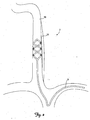
- FIG. 1 shows a perspective view of a patient's vascular system 2 including a lead 6 deployed within the system 2.
- FIG. 2 is a close up schematic view of the lead 6 deployed within the system 2.
- the vascular system 2 includes the right and left external jugular veins 10 and 14, the right and left internal jugular veins 18 and 22, the right and left subclavian veins 26 and 30, portions of which are generally aligned with the right and left vagus nerves 34 and 38.
- the lead 6 is inserted into a patient's vasculature system through the left subclavian vein 30 and into the right internal jugular vein 18.
- the lead 6 is positioned in the right internal jugular vein 18 adjacent to the right vagus nerve 34.
- the lead 6 can be inserted and advanced into the vasculature system via the right subclavian vein 26.
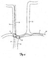
- FIGS. 3 and 4 show the lead 6 deployed within alternative locations in a patient's vasculature for stimulating the vagus nerve 34.
- the lead 6 is inserted through the right subclavian vein 30 deployed and secured in the superior vena cava 39.
- the portion of the vagus nerve 34 adjacent to the superior vena cava 39 is represented by the dashed lines in FIG. 3 .
- the lead 6 is inserted through the right subclavian vein 30 deployed and secured in the brachiocephalic vein 41.
- the portion of the vagus nerve 34 adjacent to the brachiocephalic vein 41 is represented by the dashed lines in FIG. 4 .
- FIG. 5 is a perspective view of a lead 6 according to an embodiment of the present invention.
- the lead 6 includes a lead body 42 including a proximal portion 46 and a distal portion 50 including one or more electrodes 66.
- One or more electrodes 66 are positioned along the lead body 42.
- the lead 6 includes a proximal end 52 adapted to be connected to a pulse generator or other implantable medical device.
- the lead body 42 is flexible, but substantially non-compressible along its length.
- the lead body 42 includes a plurality of conductors including individual wires, coils, or cables. These wires can be insulated conductive wires and/or molded in place with an insulator such as silicone, polyurethane, ethylene tetrafluoroethylene, or another biocompatible, insulative polymer. In one embodiment of the present invention, the lead body 42 has a co-radial design. In this embodiment, each individual conductor can be a coil including an insulative tubing. The insulated coils are then wound together in parallel to form a single coil. Alternatively, the lead body 42 is co-axial.
- each conductor is adapted to connect to an individual electrode 66 in a one-to-one manner allowing each electrode 66 to be individually addressable.
- the lead body 42 includes a lumen adapted to receive a guiding element such as a guidewire or a stylet.
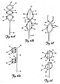
- FIGS. 6A-6E show the distal portion 50 of the lead 6 according to various embodiments of the present invention.
- the distal portion 50 is bifurcated at one or more bifurcation points 70 along the lead body 42.
- the distal portion 50 of the lead 6 is stiffer than the lead body 42 and the proximal portion 46.
- the distal portion 50 includes a superelastic material.
- Exemplary superelastic materials include Nitinol and MP35N.
- the bifurcated distal portion 50 includes at least a first elongate member 72 and a second elongate member 76.
- the first elongate member 72 forms a first spiral 82 and the second elongate member 76 forms a second spiral 86.
- Multiple spirals improve stability of the distal portion 50 of the lead 6 within the vessel by placing more friction against the venous walls. Additionally, multiple spirals fill out the space within a vessel lumen to form a tube-like inner support structure, increasing the stability of the lead in the vessel and decreasing a preference for a particular orientation.
- the spirals 82 and 86 are congruent, anti-parallel spirals having the same longitudinal axis intertwining to.form a double helix.
- the elongate members 72, 76 are connected to one another at a distal end 56 of the lead 6. Alternatively, the elongate members are not attached to one another at the distal end 56 of the lead 6.
- the spirals 82 and 86 are in serial alignment with one another. That is, as shown in FIGS. 6D and 6E , spiral 82 is proximate to spiral 86.
- the spirals 82 and 86 are interrupted by a generally straight portion 90.
- the generally straight portion 90 is configured such that it runs parallel to the nerve to be stimulated.
- a typical length of the straight portion 90 ranges from about 1 to about 8 cm as measured from a first bifurcation point to a second bifurcation point.
- the spirals 82 and 86 can wind in a clockwise or counter-clockwise direction.
- the number of turns can range from 1 ⁇ 2 turn to multiple turns as shown in FIGS. 6A and 6D .
- the pitch can be described as the distance between two points on a spiral.
- the pitch frequency ranges from zero (lasso configuration) to 5 cm, and can remain constant or vary along the spirals 82, 86.
- the spirals 82, 86 have a predetermined effective outer diameter ranging from about 5 mm to about 50 mm. According to another embodiment of the present invention, the predetermined effective outer diameter of the spirals 82, 86 ranges from about 10 mm to about 35 mm.
- the spirals 82, 86 can assume a variety of cross-sectional shapes. According to one embodiment, the spirals 82, 86 have a circular cross-sectional shape. A circular cross-sectional shape allows no bias for orientation such that when the lead is rotated within a vein the spirals 82, 86 exhibit no natural preference for a specific orientation. According to another embodiment, the spirals 82, 86 have an elliptical cross-sectional shape. The overall size, diameter and cross-sectional shape of the spirals 82, 86 can be selected depending upon the size, diameter, and shape of the vessel in which the distal portion 50 of the lead 6 is to be deployed.
- An overall length of each spiral 82, 86 ranges from about 30 mm to about 200 mm depending on the anatomical demands of the patient's anatomy. More particularly, an overall length of each spiral 82, 86 can range from about 40 to about 80 mm.
- spirals 82, 86 can increase in diameter from a proximal end of the spiral to a distal end of the spiral creating spirals 82, 86 having a predetermined shape that tapers down from a distal end of the spirals 82, 86 to a proximal end of the spirals 82, 86.
- spirals 82, 86 can have a diameter that decreases from a proximal end of spirals 82, 86 to a distal end of spirals 82, 86, creating spirals 82, 86 having a predetermined shape that tapers down from a proximal end of spirals 82, 86 towards the distal end of the spirals 82, 86.
- the spirals 82, 86 are adapted to transition from a collapsed configuration to an expanded configuration. In their expanded configuration, the spirals 82, 86 have a predetermined effective diameter and are adapted to frictionally engage at least one wall of the vessel in which the distal portion 50 is deployed. According to one embodiment of the present invention, when allowed to expand within a vessel, the spirals 82, 86 will not achieve their predetermined effective diameter as the spirals 82, 86 will be constrained from fully expanding by the walls of the vessel in which they are deployed. As such the spirals 82, 86 place a radial expansion force on the walls of the vessel, providing a mechanism for stabilizing the distal portion 50 of the lead 6 in the vessel. In one exemplary embodiment, the effective outer diameter ranges from about 5 percent to about 50 percent greater than the inner diameter of the vessel in which the distal portion 50 of the lead 6 is deployed.
- one or both of the elongate members 72, 76 can include a lumen adapted to receive a guiding element such as a stylet or a guidewire adapted to assist in delivery of the distal portion 50 to a stimulation site within a vessel.
- a guide catheter is provided to deliver the distal portion 50 to a stimulation site within a vessel.
- the stylet, guidewire, or guide catheter either alone or in combination with one another, is used to collapse (either fully or partially) the distal portion 50 including the spirals 82, 86 from an expanded configuration to a collapsed configuration (full or partial) and also to guide the distal portion 50 of the lead through the patient's vasculature system.
- the distal portion 50 can be inserted into a patient's vasculature and guided to a stimulation site within a vessel.
- the guiding element is removed, allowing the distal portion 50 to transition from a collapsed configuration to an expanded configuration.
- a guide catheter is used to deliver the distal portion 50 of the lead 6 to the stimulation site within a vessel.
- the distal portion can be partially deployed from the guide catheter and rotated or otherwise manipulated.
- the electrodes located on the distal portion can be used to acutely stimulate and thus, test potential stimulation sites.
- the guide catheter can be fully retracted and the distal portion deployed so as to secure and stabilize the distal portion at a stimulation site within the vessel such that stimulation can occur at the targeted stimulation site.
- the distal portion 50 includes a pull wire 92.
- the pull wire 92 is coupled to the distal end of the lead 6, and is operable at the proximal end of the lead 6.
- the pull wire 92 is disposed within a lumen of the lead body 42 and is adapted to be secured at the proximal end of the lead 6. Pulling on the pull wire 92 causes the distal portion 50 including the spirals 82, 86 to further expand within the vessel, causing additional radial expansion force to be placed on the vessel walls further stabilizing the distal portion 50 of the lead 6 within the vessel.
- the pull wire 92 can be secured at the proximal end of the lead 6.
- the tension placed on the pull wire 92 at the proximal end can be released, thus releasing any additional expansion force placed on the vessel walls by activating the pull wire 92 causing further radial expansion of the distal portion 50.
- a guiding element or a combination of guiding elements then can be used to reposition and/or remove the distal portion of the lead from the vessel.
- the spirals 82, 86 are variably expandable. That is, the spirals 82, 86 are adapted to expand with and adapt to the natural changes in the size and diameter of the vessel while at the same time engaging and maintaining a frictional force on the vessel walls.
- the internal geometry (diameter and inner shape) of the internal jugular vein may change with blood flow and blood pressure.
- the diameter of the vessel may be smaller than when the patient is lying down or is in a prone position.
- the spirals 82, 86 account for the difference in vessel diameter by expanding so as to maintain a frictional force on the vessel walls securing and stabilizing the distal portion 50 in the vessel.
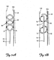
- FIGS. 7A and 7B are close-up schematic views of a distal portion 50 of a lead 6 deployed within the right internal jugular vein 18 adjacent the right vagus nerve 34.
- the spirals 82, 86 Upon deployment in a patient's vasculature, the spirals 82, 86 are adapted to radially expand such that they contact and frictionally engage an inner surface of vessel walls 102, 104 securing and stabilizing the distal portion 50 of the lead 6 at a stimulation site within the vessel.
- the stimulation site can be described as the location within a vessel adjacent a nerve or muscle which maximizes electrical stimulation to the nerve or muscle across a vessel wall.
- the spirals 82, 86 place enough radial expansion force on the vessel walls 102, 104 such that the turns of the spiral migrate outside of the original boundaries of the vessel walls 102, 104 and towards the nerve 34 to be stimulated without damaging the vessel walls 102, 104.
- any electrodes 66 located on the spirals 82, 86 are placed in closer proximity to the nerve 34.
- the electrode 66 is disposed at a distance of less than 2 mm from the nerve 34 to be stimulated.
- the spirals 82, 86 force the vessel walls 102, 104 into direct contact with the nerve 34.
- the migration of the spiral outside of the original boundaries of the vessel walls causes no damage to the vessel walls nor does the spiral erode through the vessel walls.
- a sheath of tissue forms over the spiral over an extended period of time such that it becomes encapsulated within the vessel walls.
- the outer geometry of the vessel is altered such that the outline of the spiral located within the vessel is visible.
- the lead 6 includes one or more electrodes 66.
- one or more electrodes 66 are located on one or both spirals 82, 86.
- one or more electrodes 66 are located on one or both spirals and/or the generally straight portion 90, as shown in FIG. 6E .
- At least one electrode 66 is adapted to deliver an electrical pulse transvascularly to the nerve or muscle to be stimulated.
- at least one electrode 66 is a pacing or a sensing electrode.
- stimulation can occur between electrodes 66 located on the same spiral 82 or 86, the straight portion 90, or between electrodes 66 located on different spirals 82 or 86 and/or the straight portion 90.
- the distal portion 50 is positioned within the vessel such that generally straight portion 90 is aligned in parallel along a portion of the vagus nerve 34.
- one or both spirals 82, 86 include multiple electrodes 66.
- the electrodes 66 can have the same or different polarity. Multiple electrodes 66 allow flexibility in the intravascular placement of the distal portion 50 of the lead 6. Not all of the electrodes 66 need to be orientated towards the adjacent nerve or muscle tissue in order for maximum stimulation across the vessel wall to occur.
- the circular or elliptical cross section of the spirals 82, 86 allow the distal portion 50 of the lead 6 to be rotated within the vessel so as to ensure that at least one electrode 66 is capable of delivering sufficient electrical stimulating pulse across the vessel wall.
- the electrodes 66 can be connected to multiple individual conductors through the lead body 42 allowing for them to be individually addressable.
- Individually addressable electrodes 66 allow for flexibility in electrode selection. It also allows for stimulation to occur between individual electrodes 66 on the same spiral 82 or 86 or different spirals 82 or 86 and/or the straight portion 90 providing for greater control over the current field and the direction of stimulation as well as allowing for multiple options for stimulation and sensing.
- multiple electrodes 66 are provided at an equal distance from one another along each elongate member 72, 76.
- the electrodes 66 need not have an equal spacing from one electrode 66 to another.
- the electrodes 66 are located on the straight portion 90 that interrupts the spirals 82, 86, and as such can be aligned in parallel with the nerve to be stimulated. Parallel alignment of the electrodes with the adjacent nerve increases the efficacy of stimulation as the nerve is stimulated when the electrical potential changes along the nerve.
- the lead body 42 including.the spirals 82, 86 can be rotated or otherwise manipulated such that the electrical stimulation across the vessel walls 102, 104 to the adjacent nerve is maximized.
- the electrodes 66 are pushed up against the vessel walls 102, 104, maximizing electrical transvascular stimulation.
- the spirals 82, 86 press up against the vessel walls 102, 104 with enough radial expansion force such that the spiral 82, 86 migrates outside the original boundaries of the vessel wall bringing at least one electrode 66 in closer proximity to the adjacent nerve.
- the electrodes 66 located on the lead body 42 can have any electrode configuration as is known in the art. According to one embodiment of the present invention, the electrodes 66 are ring electrodes. According to another embodiment, the electrodes 66 are partial ring electrodes. According to yet another embodiment of the present invention, the electrodes include an exposed electrode portion and an insulated electrode portion. According to this embodiment, the electrodes 66 are masked or otherwise insulated on the inner circumference of the spirals 82, 86 The exposed electrode portion is located on the outer circumference of the spiral 82, 86. Exemplary electrodes of this type are described in commonly owned and co-pending application entitled "ELECTRODE CONFIGURATIONS FOR TRANSVASCULAR NERVE STIMULATION,” assigned Serial No. 11/668,957 .
- the lead body 42 is rotated such that the exposed electrode portion is oriented towards the adjacent nerve, muscle or tissue to be stimulated.
- the exposed electrode portion is configured such that it is adapted to direct or focus current towards the stimulation target.
- the insulated electrode portion is located on the lead body 42 opposite the exposed electrode surface. The insulated electrode portion acts as a shield from the undesired stimulation of an adjacent or nearby nerve or muscle that is not the stimulation target.
- the lead 6 can be further stabilized in the internal jugular vein 34 by using a suture in a distal region of the lead body 42.
- the lead 6 is further stabilized through the wearing of a neck brace by the patient for a period of time after implantation of the lead 6.
- the lead 6 can include fixation features well known in the art, such as silicone tines or a corkscrew-shaped fixation feature (not shown) at the distal region of the lead body 42, to stabilize the lead 6 in the internal jugular vein 34.
- the fixation features can be located on one or both of the spirals 82, 86.
- the fixation feature can be located at a distal end 56 of the lead 6.
- the lead 6 can also include an area on the lead body 42 that promotes tissue in-growth.
- the area includes a roughened polymer surface on the lead body 42.
- the area includes a region of stepped or inset diameter within the lead body 42, within an electrode, or between the lead body 42 and an electrode.
- the area includes a polymer mesh, for example, a Dacron mesh, a metal mesh, for example, a stainless steel or nitinol mesh, or a bio-absorbable mesh. Examples of a bio-absorbable mesh include polyglycolic acid, poly-lactic acid, and polydioxanone.
- the lead 6 can include any combination of sutures, fixation devices, tissue in-growth areas, or a neck brace to improve its stability within the internal jugular vein 34.
- the lead 6, can be delivered to a stimulation site within a vessel adjacent a nerve, muscle, or tissue to be stimulated using standard techniques.
- the lead 6 can be inserted in a patient's vasculature system via percutaneous stick directly into a patient's internal jugular vein to deliver therapy to the vagus nerve.
- the distal portion 50 of the lead 6 is transitioned to a collapsed configuration and advanced through a patient's vasculature and delivered to a stimulation site using a guiding element such as a guide catheter.
- the spirals located at the distal portion 50 of the lead 6 transition from their collapsed configuration to their expanded configuration contacting and frictionally engaging the vessel walls of the vessel in which it is deployed.
- a stylet or one or more guidewires may be inserted into the lead lumen and/or a lumen located within one of the elongate members 72 or 76 to straighten the distal portion 50 from its predetermined spiral shape. The distal portion is then guided through the vasculature to a stimulation site located within a vessel.
- the guidewire or stylet is removed allowing the distal portion 50 of the lead 6 to return to its predetermined shape.
- Pull wires can also be used to further expand the spirals in a vessel such that they place an additional radial force on the wall further securing and stabilizing the distal portion 50 within the vessel.
- the distal portion 50 expands, contacting and frictionally engaging the vessel walls of the vessel in which it is deployed.
- the lead body 42 and, thus, the spiral members 82, 86 can be rotated within the vessel to orient the electrodes 66 towards the stimulation target. Additionally, the lead body 42 can be further rotated or positioned until a maximum or optimum electrical stimulation threshold by the electrodes 66 has been achieved across the vessel wall to the adjacent nerve or muscle to be stimulated. The stimulating pulse delivered by the electrodes can then be measured to determine if an optimal stimulation threshold has been reached, The lead 6 can be repositioned within the vessel by either rotating the lead body 42 within the vessel or reintroducing the guiding member such as the guide catheter or guidewire to collapse and/or straighten the distal portion 50 of the lead 6.
- the lead 6 can then either be repositioned and/or removed from the vessel.
- the distal portion can be partially deployed from a guide catheter in order to acutely stimulate the electrodes. Once a suitable stimulation site has been identified, the guide catheter can be retracted and the distal portion 50 fully deployed within the vessel at the stimulation site.
Description
- The present invention relates to medical electrical leads for nerve or muscle stimulation and their configurations. More specifically, the present invention relates to medical electrical lead configurations for stabilizing leads in an intravascular location adjacent a nerve to be stimulated.
- A significant amount of research has been directed both to the direct and indirect stimulation of nerves including the left and right vagus nerves, the sympathetic and parasympathetic nerves, the phrenic nerve, the sacral nerve, and the cavernous nerve to treat a wide variety of medical, psychiatric, and neurological disorders or conditions. More recently, stimulation of the vagus nerve has been proposed as a method for treating various heart conditions, including heart failure.
- Typically in the past, nerve stimulating electrodes were cuffs placed in direct contact with the nerve to be stimulated. A much less invasive approach is to stimulate the nerve through an adjacent vein using an intravascular lead. A lead including one or more electrodes is inserted into a patient's vasculature and delivered at a site within a vessel adjacent a nerve to be stimulated. However, without any additional means of stabilizing the lead within the vein, the lead can move and/or rotate causing the electrodes to migrate from the stimulation site.
- Thus, it is desirable to develop a mechanism to minimize lead rotation and movement and allow for chronic therapy to be reliably delivered.
- This object is achieved with a lead according to the independent claims. Preferred embodiments are described in the dependent claims.
-
-
FIG.1 is a schematic view of a lead deployed in a patient's internal jugular vein at a location adjacent the vagus nerve according to an embodiment of the present invention. -
FIG. 2 is a close-up, schematic view of a lead deployed in a patient's internal jugular vein as shown inFIG. 1 according to an embodiment of the present invention. -
FIG. 3 is a close-up schematic view of a lead according to an embodiment of the present invention deployed in the superior vena cava. -
FIG. 4 is a close-up schematic view of a lead according to another embodiment of the present invention deployed in the brachiocephalic vein. -
FIG. 5 is a perspective view of a lead according to an embodiment of the present invention. -
FIG. 6A-6E show side views of a distal portion of a lead according to various embodiments of the present invention. -
FIG. 7A is a close-up schematic view of a distal portion of a lead deployed in a vessel according to an embodiment of the present invention. -
FIG. 7B is a close-up schematic view of a distal portion of a lead deployed in a vessel according to an embodiment of the present invention. - While the invention is amenable to various modifications and alternative forms, specific embodiments have been shown by way of example in the drawings and are described in detail below. The intention, however, is not to limit the invention to the particular embodiments described. On the contrary, the invention is intended to cover all modifications, equivalents, and alternatives falling within the scope of the invention as defined by the appended claims.
- While the embodiments described herein generally refer to placement of a lead into the right internal jugular vein through the right or left subclavian vein, the various embodiments of the present invention as described below can be practiced at numerous sites within a patient's vasculature system. Any intravascular site that is adjacent to a nerve, muscle, or brain tissue that has the potential to benefit from stimulation is a potential site for stimulation. The term "vessel" includes all veins and arteries of the circulatory system. Additionally, the term "vessel" includes various structures of the lymphatic system, including lymph nodes, ducts, capillaries, and vessels. Likewise, as used herein, the term "vessel" also includes the various tube-like structures of the gastrointestinal system. The terms "nerve" and "nerve fiber" as used herein include a single neuron, nerve, nerve ending(s), or nerve bundle. The term "intravascular" means within the venous or arterial circulatory system, including vessels of all types and descriptions. When referring to "intravascular stimulation" in describing the embodiments of the present invention, it is meant to refer to stimulation from within the circulatory system resulting in (transvascular) stimulation of a nerve, muscle, or tissue of interest. The term "transvascular" means across a vessel or vessel wall. "Stimulation" means a stimulus, usually electrical, which causes depolarization of a cell or cells, or portion of a cell, contraction, excitation as measured by e.g., calcium or sodium influx into the cell, or an altered membrane potential across a cell.
- Vessels having sufficient diameter for catheter access which are known to have nerves running adjacent to or nearby are suitable candidates for potential stimulation sites. Exemplary sites include, but are not limited to, the following: the left and right internal jugular veins, the azygous vein, the brachiocephalic (innominate) vein, the subclavian vein, the superior vena cava, the pulmonary artery, and cardiac branch vessels. Other potential stimulation sites include, but are not limited to, the following: thoracic duct, the bile duct, and sites along the upper gastrointestinal and lower gastrointestinal tracts. Exemplary nerves to be stimulated include, but are not limited to, the following: the left and right vagus nerves, the phrenic nerve, the parasympathetic nerves, the sympathetic nerves, and the sacral nerve.
-
FIG. 1 shows a perspective view of a patient'svascular system 2 including alead 6 deployed within thesystem 2.FIG. 2 is a close up schematic view of thelead 6 deployed within thesystem 2. In general, thevascular system 2, as shown, includes the right and left externaljugular veins jugular veins subclavian veins vagus nerves FIGS. 1 and2 , thelead 6 is inserted into a patient's vasculature system through the leftsubclavian vein 30 and into the right internaljugular vein 18. Thelead 6 is positioned in the right internaljugular vein 18 adjacent to theright vagus nerve 34. Alternatively, thelead 6 can be inserted and advanced into the vasculature system via the rightsubclavian vein 26. -
FIGS. 3 and4 show thelead 6 deployed within alternative locations in a patient's vasculature for stimulating thevagus nerve 34. According to one embodiment, as shown inFIG. 3 , thelead 6 is inserted through the rightsubclavian vein 30 deployed and secured in thesuperior vena cava 39. The portion of thevagus nerve 34 adjacent to thesuperior vena cava 39 is represented by the dashed lines inFIG. 3 . According to another embodiment, as shown inFIG. 4 , thelead 6 is inserted through the rightsubclavian vein 30 deployed and secured in thebrachiocephalic vein 41. The portion of thevagus nerve 34 adjacent to thebrachiocephalic vein 41 is represented by the dashed lines inFIG. 4 . -
FIG. 5 is a perspective view of alead 6 according to an embodiment of the present invention. As shown inFIG. 5 , thelead 6 includes alead body 42 including aproximal portion 46 and adistal portion 50 including one ormore electrodes 66. One ormore electrodes 66 are positioned along thelead body 42. Additionally, thelead 6 includes aproximal end 52 adapted to be connected to a pulse generator or other implantable medical device. Thelead body 42 is flexible, but substantially non-compressible along its length. - According to one embodiment of the present invention, the
lead body 42 includes a plurality of conductors including individual wires, coils, or cables. These wires can be insulated conductive wires and/or molded in place with an insulator such as silicone, polyurethane, ethylene tetrafluoroethylene, or another biocompatible, insulative polymer. In one embodiment of the present invention, thelead body 42 has a co-radial design. In this embodiment, each individual conductor can be a coil including an insulative tubing. The insulated coils are then wound together in parallel to form a single coil. Alternatively, thelead body 42 is co-axial. According to a further embodiment of the present invention, each conductor is adapted to connect to anindividual electrode 66 in a one-to-one manner allowing eachelectrode 66 to be individually addressable. In yet a further embodiment of the present invention, thelead body 42 includes a lumen adapted to receive a guiding element such as a guidewire or a stylet. -
FIGS. 6A-6E show thedistal portion 50 of thelead 6 according to various embodiments of the present invention. As shown inFIGS 6A-6E , thedistal portion 50 is bifurcated at one or more bifurcation points 70 along thelead body 42. According to one embodiment, thedistal portion 50 of thelead 6 is stiffer than thelead body 42 and theproximal portion 46. One exemplary embodiment of such a structure is disclosed in commonly owned and co-pending application entitled "TRANSVASCULAR LEAD WITH PROXIMAL FORCE RELIEF," assigned, publication numberUS 2008/0183265 . According to another embodiment of the present invention, thedistal portion 50 includes a superelastic material. Exemplary superelastic materials include Nitinol and MP35N. - The bifurcated
distal portion 50 includes at least a firstelongate member 72 and a secondelongate member 76. The firstelongate member 72 forms afirst spiral 82 and the secondelongate member 76 forms asecond spiral 86. Multiple spirals improve stability of thedistal portion 50 of thelead 6 within the vessel by placing more friction against the venous walls. Additionally, multiple spirals fill out the space within a vessel lumen to form a tube-like inner support structure, increasing the stability of the lead in the vessel and decreasing a preference for a particular orientation. - According to the embodiments shown in
FIGS. 6A-6C , thespirals elongate members distal end 56 of thelead 6. Alternatively, the elongate members are not attached to one another at thedistal end 56 of thelead 6. - According to the embodiments shown in
FIGS. 6D and 6E , thespirals FIGS. 6D and 6E , spiral 82 is proximate to spiral 86. According to a further embodiment of the present invention, thespirals straight portion 90. The generallystraight portion 90 is configured such that it runs parallel to the nerve to be stimulated. A typical length of thestraight portion 90 ranges from about 1 to about 8 cm as measured from a first bifurcation point to a second bifurcation point. - The
spirals FIGS. 6A and 6D . The pitch can be described as the distance between two points on a spiral. The pitch frequency ranges from zero (lasso configuration) to 5 cm, and can remain constant or vary along thespirals - According to one embodiment of the present invention, the
spirals spirals - The
spirals spirals spirals spirals spirals distal portion 50 of thelead 6 is to be deployed. An overall length of each spiral 82, 86, according to an embodiment of the present invention, ranges from about 30 mm to about 200 mm depending on the anatomical demands of the patient's anatomy. More particularly, an overall length of each spiral 82, 86 can range from about 40 to about 80 mm. - According to a further embodiment of the present invention the
spirals spiral creating spirals spirals spirals spirals spirals spirals spirals spirals - The
spirals spirals distal portion 50 is deployed. According to one embodiment of the present invention, when allowed to expand within a vessel, thespirals spirals spirals distal portion 50 of thelead 6 in the vessel. In one exemplary embodiment, the effective outer diameter ranges from about 5 percent to about 50 percent greater than the inner diameter of the vessel in which thedistal portion 50 of thelead 6 is deployed. - According to an embodiment of the present invention, one or both of the
elongate members distal portion 50 to a stimulation site within a vessel. Alternatively, a guide catheter is provided to deliver thedistal portion 50 to a stimulation site within a vessel. The stylet, guidewire, or guide catheter, either alone or in combination with one another, is used to collapse (either fully or partially) thedistal portion 50 including thespirals distal portion 50 of the lead through the patient's vasculature system. Once collapsed, thedistal portion 50 can be inserted into a patient's vasculature and guided to a stimulation site within a vessel. When the stimulation site has been reached the guiding element is removed, allowing thedistal portion 50 to transition from a collapsed configuration to an expanded configuration. - According to a further embodiment of the present invention, a guide catheter is used to deliver the
distal portion 50 of thelead 6 to the stimulation site within a vessel. Once inside the targeted vessel, the distal portion can be partially deployed from the guide catheter and rotated or otherwise manipulated. The electrodes located on the distal portion can be used to acutely stimulate and thus, test potential stimulation sites. Once a stimulation site has been selected using the information gained through acute stimulation, the guide catheter can be fully retracted and the distal portion deployed so as to secure and stabilize the distal portion at a stimulation site within the vessel such that stimulation can occur at the targeted stimulation site. - According to yet a further embodiment of the present invention, as shown in
FIG. 6B , thedistal portion 50 includes apull wire 92. Thepull wire 92 is coupled to the distal end of thelead 6, and is operable at the proximal end of thelead 6. According to one exemplary embodiment, thepull wire 92 is disposed within a lumen of thelead body 42 and is adapted to be secured at the proximal end of thelead 6. Pulling on thepull wire 92 causes thedistal portion 50 including thespirals distal portion 50 of thelead 6 within the vessel. When thedistal portion 50 has been stabilized, thepull wire 92 can be secured at the proximal end of thelead 6. Likewise, when it is desirable to reposition or remove the distal portion of the lead, the tension placed on thepull wire 92 at the proximal end can be released, thus releasing any additional expansion force placed on the vessel walls by activating thepull wire 92 causing further radial expansion of thedistal portion 50. A guiding element or a combination of guiding elements then can be used to reposition and/or remove the distal portion of the lead from the vessel. - According to another embodiment of the present invention, the
spirals spirals spirals distal portion 50 in the vessel. -
FIGS. 7A and 7B are close-up schematic views of adistal portion 50 of alead 6 deployed within the right internaljugular vein 18 adjacent theright vagus nerve 34. Upon deployment in a patient's vasculature, thespirals vessel walls distal portion 50 of thelead 6 at a stimulation site within the vessel. The stimulation site can be described as the location within a vessel adjacent a nerve or muscle which maximizes electrical stimulation to the nerve or muscle across a vessel wall. According to an embodiment of the present invention, thespirals vessel walls vessel walls nerve 34 to be stimulated without damaging thevessel walls electrodes 66 located on thespirals nerve 34. In one exemplary embodiment, theelectrode 66 is disposed at a distance of less than 2 mm from thenerve 34 to be stimulated. In another exemplary embodiment of the present invention, thespirals vessel walls nerve 34. - The migration of the spiral outside of the original boundaries of the vessel walls causes no damage to the vessel walls nor does the spiral erode through the vessel walls. A sheath of tissue forms over the spiral over an extended period of time such that it becomes encapsulated within the vessel walls. The outer geometry of the vessel is altered such that the outline of the spiral located within the vessel is visible.
- As shown in
FIGS. 1-7B , thelead 6 includes one ormore electrodes 66. According to an embodiment of the present invention, one ormore electrodes 66 are located on one or bothspirals more electrodes 66 are located on one or both spirals and/or the generallystraight portion 90, as shown inFIG. 6E . At least oneelectrode 66 is adapted to deliver an electrical pulse transvascularly to the nerve or muscle to be stimulated. Additionally, according to a further embodiment of the present invention, at least oneelectrode 66 is a pacing or a sensing electrode. Depending upon the application and desired result, stimulation can occur betweenelectrodes 66 located on thesame spiral straight portion 90, or betweenelectrodes 66 located ondifferent spirals straight portion 90. According to a further exemplary embodiment, as shown inFIG. 7B , thedistal portion 50 is positioned within the vessel such that generallystraight portion 90 is aligned in parallel along a portion of thevagus nerve 34. - According to another embodiment of the present invention, one or both
spirals multiple electrodes 66. Theelectrodes 66 can have the same or different polarity.Multiple electrodes 66 allow flexibility in the intravascular placement of thedistal portion 50 of thelead 6. Not all of theelectrodes 66 need to be orientated towards the adjacent nerve or muscle tissue in order for maximum stimulation across the vessel wall to occur. Likewise, the circular or elliptical cross section of thespirals distal portion 50 of thelead 6 to be rotated within the vessel so as to ensure that at least oneelectrode 66 is capable of delivering sufficient electrical stimulating pulse across the vessel wall. Additionally, theelectrodes 66 can be connected to multiple individual conductors through thelead body 42 allowing for them to be individually addressable. Individuallyaddressable electrodes 66 allow for flexibility in electrode selection. It also allows for stimulation to occur betweenindividual electrodes 66 on thesame spiral different spirals straight portion 90 providing for greater control over the current field and the direction of stimulation as well as allowing for multiple options for stimulation and sensing. - According to a further embodiment of the present invention, as best shown in
FIGS. 6A-6E ,multiple electrodes 66 are provided at an equal distance from one another along eachelongate member electrodes 66 need not have an equal spacing from oneelectrode 66 to another. Additionally, as shown inFIG. 6D , theelectrodes 66 are located on thestraight portion 90 that interrupts thespirals lead body 42 including.thespirals vessel walls FIGS. 7A and 7B , as thespirals electrodes 66 are pushed up against thevessel walls spirals vessel walls electrode 66 in closer proximity to the adjacent nerve. - The
electrodes 66 located on thelead body 42 can have any electrode configuration as is known in the art. According to one embodiment of the present invention, theelectrodes 66 are ring electrodes. According to another embodiment, theelectrodes 66 are partial ring electrodes. According to yet another embodiment of the present invention, the electrodes include an exposed electrode portion and an insulated electrode portion. According to this embodiment, theelectrodes 66 are masked or otherwise insulated on the inner circumference of thespirals 11/668,957 lead body 42 is rotated such that the exposed electrode portion is oriented towards the adjacent nerve, muscle or tissue to be stimulated. The exposed electrode portion is configured such that it is adapted to direct or focus current towards the stimulation target. The insulated electrode portion is located on thelead body 42 opposite the exposed electrode surface. The insulated electrode portion acts as a shield from the undesired stimulation of an adjacent or nearby nerve or muscle that is not the stimulation target. - The
lead 6 can be further stabilized in the internaljugular vein 34 by using a suture in a distal region of thelead body 42. In one embodiment, thelead 6 is further stabilized through the wearing of a neck brace by the patient for a period of time after implantation of thelead 6. In an alternative embodiment, thelead 6 can include fixation features well known in the art, such as silicone tines or a corkscrew-shaped fixation feature (not shown) at the distal region of thelead body 42, to stabilize thelead 6 in the internaljugular vein 34. In an alternate embodiment the fixation features can be located on one or both of thespirals distal end 56 of thelead 6. Thelead 6 can also include an area on thelead body 42 that promotes tissue in-growth. In one embodiment, the area includes a roughened polymer surface on thelead body 42. In alternative embodiments, the area includes a region of stepped or inset diameter within thelead body 42, within an electrode, or between thelead body 42 and an electrode. In other embodiments, the area includes a polymer mesh, for example, a Dacron mesh, a metal mesh, for example, a stainless steel or nitinol mesh, or a bio-absorbable mesh. Examples of a bio-absorbable mesh include polyglycolic acid, poly-lactic acid, and polydioxanone. Thelead 6 can include any combination of sutures, fixation devices, tissue in-growth areas, or a neck brace to improve its stability within the internaljugular vein 34. - The
lead 6, according to various embodiments of the present invention, can be delivered to a stimulation site within a vessel adjacent a nerve, muscle, or tissue to be stimulated using standard techniques. According to one embodiment of the present invention, thelead 6 can be inserted in a patient's vasculature system via percutaneous stick directly into a patient's internal jugular vein to deliver therapy to the vagus nerve. According to another embodiment of the present invention, thedistal portion 50 of thelead 6 is transitioned to a collapsed configuration and advanced through a patient's vasculature and delivered to a stimulation site using a guiding element such as a guide catheter. Once the site has been reached and the guide catheter is retracted, the spirals located at thedistal portion 50 of thelead 6 transition from their collapsed configuration to their expanded configuration contacting and frictionally engaging the vessel walls of the vessel in which it is deployed. Likewise, a stylet or one or more guidewires may be inserted into the lead lumen and/or a lumen located within one of theelongate members distal portion 50 from its predetermined spiral shape. The distal portion is then guided through the vasculature to a stimulation site located within a vessel. - Once a stimulation site has been reached, the guidewire or stylet is removed allowing the
distal portion 50 of thelead 6 to return to its predetermined shape. Pull wires can also be used to further expand the spirals in a vessel such that they place an additional radial force on the wall further securing and stabilizing thedistal portion 50 within the vessel. Whatever the delivery method, once the distal portion has reached a stimulation site within a vessel adjacent a nerve to be stimulated, thedistal portion 50 expands, contacting and frictionally engaging the vessel walls of the vessel in which it is deployed. - The
lead body 42 and, thus, thespiral members electrodes 66 towards the stimulation target. Additionally, thelead body 42 can be further rotated or positioned until a maximum or optimum electrical stimulation threshold by theelectrodes 66 has been achieved across the vessel wall to the adjacent nerve or muscle to be stimulated. The stimulating pulse delivered by the electrodes can then be measured to determine if an optimal stimulation threshold has been reached, Thelead 6 can be repositioned within the vessel by either rotating thelead body 42 within the vessel or reintroducing the guiding member such as the guide catheter or guidewire to collapse and/or straighten thedistal portion 50 of thelead 6. - The
lead 6 can then either be repositioned and/or removed from the vessel. According to a further embodiment of the present invention, the distal portion can be partially deployed from a guide catheter in order to acutely stimulate the electrodes. Once a suitable stimulation site has been identified, the guide catheter can be retracted and thedistal portion 50 fully deployed within the vessel at the stimulation site. - Various modifications and additions can be made to the exemplary embodiments discussed without departing from the scope of the present invention. For example, while the embodiments described above refer to particular features, the scope of this invention also includes embodiments having different combinations of features and embodiments that do not include all of the described features. Accordingly, the scope of the present invention is intended to embrace all such alternatives, modifications, and variations as fall within the scope of the claims.
Claims (13)
- An intravascular lead adapted to be deployed to a stimulation site within an internal jugular vein having a vessel wall adjacent a vagus nerve, the lead comprising:a lead body including a proximal end adapted to be connected to a pulse generator and a bifurcated distal portion for securing and stabilizing the lead in the vessel, the bifurcated distal portion comprising at least one bifurcation point and a first elongated member and a second elongated member, the first and second elongated members branching away and extending distally from the at least one bifurcation point, the first elongated member forming a first spiral and the second elongated member forming a second spiral, wherein the first and second spirals are congruent, anti-parallel spirals having a same longitudinal axis forming a double helix and wherein the spirals are adapted to transition from a collapsed configuration for inserting the lead through a patient's vasculature system to an expanded configuration, wherein in the expanded configuration the spirals have a predetermined effective outer diameter ranging from about 5 to about 50% greater than the inner diameter of the internal jugular vein and are adapted to frictionally engage the vessel wall of the vessel in which the distal portion is deployed;a plurality of conductors included with the lead body;a plurality of electrodes adapted to deliver an electrical pulse transvascularly to the nerve located on the distal portion, each individual electrode comprising a masked portion and an exposed portion and coupled to an individual conductor such that each electrode is individually addressable, wherein when the distal portion is expanded, the exposed portion of at least one electrode is located on an outer circumference of at least one spiral and is adapted to be oriented in a direction towards the vagus nerve and the masked portion is located on an inner circumference of the at least one spiral.
- The intravascular lead according to claim 1, wherein at least a first electrode is located on the first spiral and at least a second electrode is located on the second spiral.
- The intravascular lead according to claim 1, wherein the spirals have an outer effective diameter ranging from about 5 percent to about 20 percent greater than an inner diameter of the internal jugular vein in which the distal portion is deployed.
- The intravascular lead according to claim 1, wherein when the distal portion is expanded the exposed portions of at least two electrodes are oriented in a direction towards and are adapted to be aligned with the vagus nerve.
- The intravascular lead according to claim 1, wherein the distal portion is adapted to urge the vessel wall in a direction towards the vagus nerve so that a distance between one or more electrodes and the vagus nerve is less than 2 mm.
- The intravascular lead according to claim 1, wherein the distal portion comprises a superelastic material selected from the group consisting of Nitinol and MP35N.
- The intravascular lead according to claim 1, further comprising a pull wire attached to a distal portion of the lead.
- An intravascular lead adapted to be deployed to a stimulation site within an internal jugular vein having a vessel wall adjacent a vagus nerve, the lead comprising:a lead body including a proximal end adapted to be connected to a pulse generator and a bifurcated distal portion, the bifurcated distal portion comprising at least one bifurcation point, a first elongated member forming a first spiral, a second elongated member forming a second spiral, wherein the first and second elongated members branch away and extend distally from the at least one bifurcation point, and a generally straight portion occurring between the first spiral and the second spiral, wherein each of the first and second spirals have a predetermined effective outer diameter ranging from about 5 to about 50% greater than the inner diameter of the internal jugular vein and are adapted to expand so as to impart a lateral force on the vessel wall to urge the vessel wall in a direction towards the vagus nerve and to secure and stabilize the distal portion within the vessel;a plurality of conductors extending within the lead body from the proximal end to the distal end; andat least a first electrode located on the first spiral and at least a second electrode located on the second spiral, each of the first and second electrodes coupled to an individual conductor extending within the lead body and adapted to deliver an electrical pulse transvascularly to the vagus nerve and each electrode comprising a masked portion and an exposed portion, wherein when the distal portion is expanded, the exposed portion of at least the first electrode is located on an outer circumference of the first spiral and is adapted to be oriented in a direction towards the vagus nerve and the masked portion is located on an inner circumference of the first spiral.
- The intravascular lead according to claim 8, wherein the second elongated member comprises a super-elastic wire.
- The intravascular lead according to claim 8, wherein the first and second electrodes are in alignment with each other such that they are adapted to be aligned in parallel with the nerve to be stimulated.
- The intravascular lead according to claim 8, wherein the first spiral is in serial alignment with the second spiral.
- The intravascular lead according to claim 8, wherein the spirals are configured to expand and frictionally engage at least one vessel wall upon deployment in a vessel.
- The intravascular lead according to claim 8, wherein the distal portion comprises a superelastic material selected from the group consisting of Nitinol and MP35N.
Applications Claiming Priority (2)
| Application Number | Priority Date | Filing Date | Title |
|---|---|---|---|
| US11/668,887 US7949409B2 (en) | 2007-01-30 | 2007-01-30 | Dual spiral lead configurations |
| PCT/US2007/086119 WO2008094345A1 (en) | 2007-01-30 | 2007-11-30 | Dual spiral lead configurations |
Publications (2)
| Publication Number | Publication Date |
|---|---|
| EP2125105A1 EP2125105A1 (en) | 2009-12-02 |
| EP2125105B1 true EP2125105B1 (en) | 2015-08-05 |
Family
ID=39181269
Family Applications (1)
| Application Number | Title | Priority Date | Filing Date |
|---|---|---|---|
| EP07865019.9A Not-in-force EP2125105B1 (en) | 2007-01-30 | 2007-11-30 | Dual spiral lead configurations |
Country Status (6)
| Country | Link |
|---|---|
| US (1) | US7949409B2 (en) |
| EP (1) | EP2125105B1 (en) |
| JP (1) | JP5150646B2 (en) |
| CN (1) | CN101610810A (en) |
| AU (1) | AU2007345602B2 (en) |
| WO (1) | WO2008094345A1 (en) |
Families Citing this family (92)
| Publication number | Priority date | Publication date | Assignee | Title |
|---|---|---|---|---|
| JP2009502302A (en) | 2005-07-25 | 2009-01-29 | グロス,ヨシ | Electrical stimulation of blood vessels |
| US20070123923A1 (en) * | 2005-11-30 | 2007-05-31 | Lindstrom Curtis C | Implantable medical device minimizing rotation and dislocation |
| US9913982B2 (en) | 2011-01-28 | 2018-03-13 | Cyberonics, Inc. | Obstructive sleep apnea treatment devices, systems and methods |
| AU2007313319B2 (en) | 2006-10-13 | 2012-03-22 | Cyberonics, Inc. | Obstructive sleep apnea treatment devices, systems and methods |
| US9744354B2 (en) | 2008-12-31 | 2017-08-29 | Cyberonics, Inc. | Obstructive sleep apnea treatment devices, systems and methods |
| US9186511B2 (en) | 2006-10-13 | 2015-11-17 | Cyberonics, Inc. | Obstructive sleep apnea treatment devices, systems and methods |
| US9205262B2 (en) | 2011-05-12 | 2015-12-08 | Cyberonics, Inc. | Devices and methods for sleep apnea treatment |
| US8855771B2 (en) | 2011-01-28 | 2014-10-07 | Cyberonics, Inc. | Screening devices and methods for obstructive sleep apnea therapy |
| US8909341B2 (en) | 2007-01-22 | 2014-12-09 | Respicardia, Inc. | Device and method for the treatment of breathing disorders and cardiac disorders |
| US8571662B2 (en) | 2007-01-29 | 2013-10-29 | Simon Fraser University | Transvascular nerve stimulation apparatus and methods |
| US20080183187A1 (en) * | 2007-01-30 | 2008-07-31 | Cardiac Pacemakers, Inc. | Direct delivery system for transvascular lead |
| US20080183265A1 (en) * | 2007-01-30 | 2008-07-31 | Cardiac Pacemakers, Inc. | Transvascular lead with proximal force relief |
| US7917230B2 (en) | 2007-01-30 | 2011-03-29 | Cardiac Pacemakers, Inc. | Neurostimulating lead having a stent-like anchor |
| US8244378B2 (en) | 2007-01-30 | 2012-08-14 | Cardiac Pacemakers, Inc. | Spiral configurations for intravascular lead stability |
| US20080183255A1 (en) * | 2007-01-30 | 2008-07-31 | Cardiac Pacemakers, Inc. | Side port lead delivery system |
| US20080183264A1 (en) * | 2007-01-30 | 2008-07-31 | Cardiac Pacemakers, Inc. | Electrode configurations for transvascular nerve stimulation |
| US9987488B1 (en) | 2007-06-27 | 2018-06-05 | Respicardia, Inc. | Detecting and treating disordered breathing |
| US8135471B2 (en) * | 2007-08-28 | 2012-03-13 | Cardiac Pacemakers, Inc. | Method and apparatus for inspiratory muscle stimulation using implantable device |
| US8538535B2 (en) | 2010-08-05 | 2013-09-17 | Rainbow Medical Ltd. | Enhancing perfusion by contraction |
| US9199075B1 (en) | 2008-02-07 | 2015-12-01 | Respicardia, Inc. | Transvascular medical lead |
| US7925352B2 (en) | 2008-03-27 | 2011-04-12 | Synecor Llc | System and method for transvascularly stimulating contents of the carotid sheath |
| US20100137949A1 (en) * | 2008-05-27 | 2010-06-03 | The Cleveland Clinic Foundation | Bifurcated electrical lead and method of use |
| JP5247884B2 (en) * | 2008-08-12 | 2013-07-24 | カーディアック ペースメイカーズ, インコーポレイテッド | Implantable lead and coronary venous pressure sensor device |
| JP5547200B2 (en) | 2008-10-01 | 2014-07-09 | インスパイア・メディカル・システムズ・インコーポレイテッド | Transvenous treatment to treat sleep apnea |
| US8652129B2 (en) | 2008-12-31 | 2014-02-18 | Medtronic Ardian Luxembourg S.A.R.L. | Apparatus, systems, and methods for achieving intravascular, thermally-induced renal neuromodulation |
| EP2416845B1 (en) | 2009-03-31 | 2015-03-18 | Inspire Medical Systems, Inc. | Percutaneous access for systems of treating sleep-related disordered breathing |
| US8233987B2 (en) | 2009-09-10 | 2012-07-31 | Respicardia, Inc. | Respiratory rectification |
| US9468755B2 (en) * | 2009-09-30 | 2016-10-18 | Respicardia, Inc. | Medical lead with preformed bias |
| CA2792153C (en) * | 2010-03-23 | 2018-05-15 | Boston Scientific Neuromodulation Corporation | Helical radial spacing of contacts on a cylindrical lead |
| US8620450B2 (en) | 2010-07-19 | 2013-12-31 | Cardiac Pacemakers, Inc. | Minimally invasive lead system for vagus nerve stimulation |
| EP2701795B1 (en) | 2011-04-28 | 2020-12-09 | Interventional Autonomics Corporation | Neuromodulation systems for treating acute heart failure syndromes |
| US9220887B2 (en) * | 2011-06-09 | 2015-12-29 | Astora Women's Health LLC | Electrode lead including a deployable tissue anchor |
| US20130072995A1 (en) | 2011-07-11 | 2013-03-21 | Terrance Ransbury | Catheter system for acute neuromodulation |
| US9067071B2 (en) | 2011-07-11 | 2015-06-30 | Interventional Autonomics Corporation | System and method for neuromodulation |
| US9446240B2 (en) | 2011-07-11 | 2016-09-20 | Interventional Autonomics Corporation | System and method for neuromodulation |
| JP2013034535A (en) * | 2011-08-04 | 2013-02-21 | Olympus Corp | Electrical stimulation electrode assembly |
| WO2013035092A2 (en) | 2011-09-09 | 2013-03-14 | Enopace Biomedical Ltd. | Wireless endovascular stent-based electrodes |
| US20140288667A1 (en) | 2011-10-04 | 2014-09-25 | Thomas James Oxley | Sensing or Stimulating Activity of Tissue |
| US20140324142A1 (en) * | 2011-11-08 | 2014-10-30 | Enopace Biomedical Ltd. | Acute myocardial infarction treatment by electrical stimulation of the thoracic aorta |
| ITPD20110383A1 (en) * | 2011-12-05 | 2013-06-06 | Cardiac Impulse Srl | ELECTROCATETER FOR NEUROSTIMULATION |
| US20130184801A1 (en) * | 2012-01-13 | 2013-07-18 | Pacesetter, Inc. | Lead shaped for stimulation at the base left ventricle |
| EP3556427B1 (en) | 2012-03-05 | 2022-06-08 | Lungpacer Medical Inc. | Transvascular nerve stimulation apparatus |
| JP5936409B2 (en) * | 2012-03-26 | 2016-06-22 | 国立研究開発法人国立循環器病研究センター | Electrode unit and tissue stimulation system |
| US9439598B2 (en) | 2012-04-12 | 2016-09-13 | NeuroMedic, Inc. | Mapping and ablation of nerves within arteries and tissues |
| US11395921B2 (en) * | 2012-04-29 | 2022-07-26 | Nuxcel2 Llc | Intravascular electrode arrays for neuromodulation |
| CN104684614B (en) | 2012-06-21 | 2017-10-17 | 西蒙·弗雷泽大学 | The diaphragm pacing system and application method of intravascular |
| DE102013105010B4 (en) * | 2013-05-15 | 2020-09-10 | Bildungszentrum für informationsverarbeitende Berufe gGmbH | Measurement system, arrangement and method for evaluating nerve signals |
| US9370652B2 (en) | 2013-07-24 | 2016-06-21 | Gimer Medical Co. Ltd. | Desensitizing device |
| CN107569771B (en) * | 2013-08-26 | 2021-03-12 | 精能医学股份有限公司 | Electrical stimulator, stimulation method using same and electrical stimulation system |
| WO2015042900A1 (en) * | 2013-09-29 | 2015-04-02 | Covidien Lp | Medical treatment devices having adjustable length and/or diameter |
| CN104510527B (en) * | 2013-09-29 | 2017-04-12 | 柯惠有限合伙公司 | Medical treatment device adjustable in length and/or diameter |
| US9956408B2 (en) | 2013-10-09 | 2018-05-01 | Gimer Medical Co. Ltd. | Method for reducing spasticity and non-transitory computer-readable medium thereof |
| US10632310B2 (en) | 2013-10-09 | 2020-04-28 | GiMer Medical Co., Ltd. | Electronic stimulation device, method of treatment and electronic stimulation system |
| US10183165B2 (en) | 2013-10-09 | 2019-01-22 | GiMer Medical Co., Ltd. | Method of reducing renal hypertension and computer-readable medium |
| US9526889B2 (en) | 2013-10-09 | 2016-12-27 | GiMer Medical Co., Ltd. | Electromagnetic stimulation device for changing nerve threshold |
| US10086197B2 (en) | 2013-10-09 | 2018-10-02 | GiMer Medical Co., Ltd. | Method for reducing overactive bladder syndrome and computer-readable medium thereof |
| US10639476B2 (en) | 2013-10-09 | 2020-05-05 | GiMer Medical Co., Ltd. | Electronic stimulation device, method of treatment and electronic stimulation system |
| US10086201B2 (en) | 2013-10-09 | 2018-10-02 | GiMer Medical Co., Ltd. | Electronic stimulation device, method of treatment and electronic stimulation system |
| CN108836586B (en) | 2013-11-06 | 2021-04-06 | 伊诺佩斯生医有限公司 | Wireless intravascular stent-based electrode |
| WO2015075548A1 (en) | 2013-11-22 | 2015-05-28 | Simon Fraser University | Apparatus and methods for assisted breathing by transvascular nerve stimulation |
| AU2015208640B2 (en) | 2014-01-21 | 2020-02-20 | Lungpacer Medical Inc. | Systems and related methods for optimization of multi-electrode nerve pacing |
| US11383083B2 (en) | 2014-02-11 | 2022-07-12 | Livanova Usa, Inc. | Systems and methods of detecting and treating obstructive sleep apnea |
| AU2015229669A1 (en) * | 2014-03-09 | 2016-09-29 | Neuro Tronik Ip Holding (Jersey) Limited | Systems and methods for neuromodulation of sympathetic and parasympathetic cardiac nerves |
| JP6274972B2 (en) * | 2014-05-29 | 2018-02-07 | オリンパス株式会社 | Medical electrical stimulation electrode and medical electrical stimulation device |
| US10328268B2 (en) | 2014-09-04 | 2019-06-25 | AtaCor Medical, Inc. | Cardiac pacing |
| US10743960B2 (en) | 2014-09-04 | 2020-08-18 | AtaCor Medical, Inc. | Cardiac arrhythmia treatment devices and delivery |
| JP2016077801A (en) * | 2014-10-22 | 2016-05-16 | オリンパス株式会社 | Electrode unit and nerve stimulation system |
| US11097109B2 (en) | 2014-11-24 | 2021-08-24 | AtaCor Medical, Inc. | Cardiac pacing sensing and control |
| JP6632191B2 (en) * | 2015-01-08 | 2020-01-22 | アドリアカイム株式会社 | Nerve stimulation electrode |
| JP6576367B2 (en) * | 2015-01-13 | 2019-09-18 | アドリアカイム株式会社 | Nerve stimulation electrode |
| JP6438497B2 (en) * | 2015-02-03 | 2018-12-12 | オリンパス株式会社 | Medical stimulation electrode |
| JP6491939B2 (en) * | 2015-04-22 | 2019-03-27 | オリンパス株式会社 | Nerve stimulation system |
| AU2016341230B2 (en) | 2015-10-20 | 2020-01-16 | The University Of Melbourne | Medical device for sensing and or stimulating tissue |
| WO2017136346A1 (en) | 2016-02-05 | 2017-08-10 | Boston Scientfic Neuromodulation Corporation | Implantable optical stimulation lead |
| US11612749B2 (en) | 2016-04-01 | 2023-03-28 | Livanova Usa, Inc. | Vagus nerve stimulation patient selection |
| CN108882864A (en) * | 2016-04-01 | 2018-11-23 | 柯柏拉医疗股份有限公司 | Shaped epicardial lead and place system and method |
| DE102016116871A1 (en) * | 2016-09-08 | 2018-03-08 | Phenox Gmbh | Device and method for the prevention and treatment of vasospasm |
| CN111132726B (en) | 2017-04-18 | 2023-10-31 | 墨尔本大学 | Intravascular device for sensing and/or stimulating tissue |
| US10293164B2 (en) | 2017-05-26 | 2019-05-21 | Lungpacer Medical Inc. | Apparatus and methods for assisted breathing by transvascular nerve stimulation |
| EP4115942B1 (en) | 2017-06-30 | 2024-04-24 | Lungpacer Medical Inc. | System for prevention, moderation, and/or treatment of cognitive injury |
| US10195429B1 (en) | 2017-08-02 | 2019-02-05 | Lungpacer Medical Inc. | Systems and methods for intravascular catheter positioning and/or nerve stimulation |
| US10940308B2 (en) | 2017-08-04 | 2021-03-09 | Lungpacer Medical Inc. | Systems and methods for trans-esophageal sympathetic ganglion recruitment |
| US11565131B2 (en) | 2018-03-23 | 2023-01-31 | Boston Scientific Neuromodulation Corporation | Optical stimulation systems with calibration and methods of making and using |
| US11524174B2 (en) | 2018-03-23 | 2022-12-13 | Boston Scientific Neuromodulation Corporation | Optical stimulation system with on-demand monitoring and methods of making and using |
| EP3877043A4 (en) | 2018-11-08 | 2022-08-24 | Lungpacer Medical Inc. | Stimulation systems and related user interfaces |
| EP3840824A1 (en) | 2018-11-16 | 2021-06-30 | Boston Scientific Neuromodulation Corporation | An optical stimulation system with on-demand monitoring and methods of making |
| JP2022532375A (en) | 2019-05-16 | 2022-07-14 | ラングペーサー メディカル インコーポレイテッド | Systems and methods for detection and stimulation |
| WO2020243534A1 (en) | 2019-05-29 | 2020-12-03 | AtaCor Medical, Inc. | Implantable electrical leads and associated delivery systems |
| JP2022536478A (en) | 2019-06-12 | 2022-08-17 | ラングペーサー メディカル インコーポレイテッド | Circuits for medical stimulation systems |
| US11666771B2 (en) * | 2020-05-29 | 2023-06-06 | AtaCor Medical, Inc. | Implantable electrical leads and associated delivery systems |
| US11806547B2 (en) | 2020-09-04 | 2023-11-07 | Boston Scientific Neuromodulation Corporation | Stimulation systems with a lens arrangement for light coupling and methods of making and using |
| US11400299B1 (en) | 2021-09-14 | 2022-08-02 | Rainbow Medical Ltd. | Flexible antenna for stimulator |
Citations (3)
| Publication number | Priority date | Publication date | Assignee | Title |
|---|---|---|---|---|
| US4154247A (en) * | 1977-04-01 | 1979-05-15 | Medtronic, Inc. | Formable cardiac pacer lead and method of assembly and attachment to a body organ |
| DE10103288A1 (en) * | 2001-01-25 | 2002-08-01 | Patrick Schauerte | Vascular lock for intravascular nerve stimulation and fluid infusion |
| US20060229677A1 (en) * | 2005-04-11 | 2006-10-12 | Cardiac Pacemakers, Inc. | Transvascular neural stimulation device |
Family Cites Families (109)
| Publication number | Priority date | Publication date | Assignee | Title |
|---|---|---|---|---|
| US4365634A (en) * | 1979-12-06 | 1982-12-28 | C. R. Bard, Inc. | Medical electrode construction |
| US4414986A (en) * | 1982-01-29 | 1983-11-15 | Medtronic, Inc. | Biomedical stimulation lead |
| US4774949A (en) * | 1983-06-14 | 1988-10-04 | Fogarty Thomas J | Deflector guiding catheter |
| DE8717643U1 (en) * | 1987-05-12 | 1989-09-21 | Foerster, Ernst, Dr.Med. Dr.Rer.Nat. | |
| US4944088A (en) * | 1988-05-25 | 1990-07-31 | Medtronic, Inc. | Ring electrode for multiconductor pacing leads |
| US4920979A (en) * | 1988-10-12 | 1990-05-01 | Huntington Medical Research Institute | Bidirectional helical electrode for nerve stimulation |
| US5016808A (en) * | 1989-09-14 | 1991-05-21 | Cardiac Pacemakers, Inc. | Implantable tapered spiral endocardial lead for use in internal defibrillation |
| US5265608A (en) * | 1990-02-22 | 1993-11-30 | Medtronic, Inc. | Steroid eluting electrode for peripheral nerve stimulation |
| US5221261A (en) * | 1990-04-12 | 1993-06-22 | Schneider (Usa) Inc. | Radially expandable fixation member |
| US5251634A (en) * | 1991-05-03 | 1993-10-12 | Cyberonics, Inc. | Helical nerve electrode |
| JPH066170B2 (en) * | 1991-08-28 | 1994-01-26 | 中島 博 | Pacemaker pacing leads |
| US5330515A (en) * | 1992-06-17 | 1994-07-19 | Cyberonics, Inc. | Treatment of pain by vagal afferent stimulation |
| AU5295493A (en) | 1992-10-01 | 1994-04-26 | Cardiac Pacemakers, Inc. | Stent-type defibrillation electrode structures |
| SE9203732D0 (en) * | 1992-12-11 | 1992-12-11 | Siemens Elema Ab | ELECTRIC SYSTEM FOR DEFIBRILLATOR |
| SE9203733D0 (en) * | 1992-12-11 | 1992-12-11 | Siemens Elema Ab | defibrillation |
| US5387233A (en) * | 1993-01-11 | 1995-02-07 | Incontrol, Inc. | Intravenous cardiac lead with improved fixation and method |
| US5792187A (en) * | 1993-02-22 | 1998-08-11 | Angeion Corporation | Neuro-stimulation to control pain during cardioversion defibrillation |
| US5383922A (en) * | 1993-03-15 | 1995-01-24 | Medtronic, Inc. | RF lead fixation and implantable lead |
| US5476498A (en) * | 1994-08-15 | 1995-12-19 | Incontrol, Inc. | Coronary sinus channel lead and method |
| US5540730A (en) * | 1995-06-06 | 1996-07-30 | Cyberonics, Inc. | Treatment of motility disorders by nerve stimulation |
| US5766203A (en) * | 1995-07-20 | 1998-06-16 | Intelliwire, Inc. | Sheath with expandable distal extremity and balloon catheters and stents for use therewith and method |
| US5772693A (en) * | 1996-02-09 | 1998-06-30 | Cardiac Control Systems, Inc. | Single preformed catheter configuration for a dual-chamber pacemaker system |
| US5776178A (en) | 1996-02-21 | 1998-07-07 | Medtronic, Inc. | Medical electrical lead with surface treatment for enhanced fixation |
| US5755761A (en) * | 1996-04-26 | 1998-05-26 | Pharmatarget, Inc. | Atrial pacing catheter and method having multiple electrodes in the right atrium and coronary sinus |
| US6449507B1 (en) * | 1996-04-30 | 2002-09-10 | Medtronic, Inc. | Method and system for nerve stimulation prior to and during a medical procedure |
| US7269457B2 (en) * | 1996-04-30 | 2007-09-11 | Medtronic, Inc. | Method and system for vagal nerve stimulation with multi-site cardiac pacing |
| US7225019B2 (en) * | 1996-04-30 | 2007-05-29 | Medtronic, Inc. | Method and system for nerve stimulation and cardiac sensing prior to and during a medical procedure |
| US6006134A (en) * | 1998-04-30 | 1999-12-21 | Medtronic, Inc. | Method and device for electronically controlling the beating of a heart using venous electrical stimulation of nerve fibers |
| USRE38705E1 (en) * | 1996-04-30 | 2005-02-22 | Medtronic, Inc. | Method and device for electronically controlling the beating of a heart using venous electrical stimulation of nerve fibers |
| US5755714A (en) | 1996-09-17 | 1998-05-26 | Eclipse Surgical Technologies, Inc. | Shaped catheter for transmyocardial revascularization |
| DE19645573A1 (en) * | 1996-11-05 | 1998-05-07 | Bodenseewerk Geraetetech | All-round observation device |
| EP0842640A1 (en) | 1996-11-13 | 1998-05-20 | Sulzer Osypka GmbH | Heart catheter with electrode positioned on a distensible element |
| US5803928A (en) * | 1997-01-24 | 1998-09-08 | Cardiac Pacemakers, Inc. | Side access "over the wire" pacing lead |
| US5954761A (en) * | 1997-03-25 | 1999-09-21 | Intermedics Inc. | Implantable endocardial lead assembly having a stent |
| US6479523B1 (en) * | 1997-08-26 | 2002-11-12 | Emory University | Pharmacologic drug combination in vagal-induced asystole |
| US5922014A (en) | 1997-09-02 | 1999-07-13 | Medtronic, Inc. | Single pass lead and method of use |
| US5871531A (en) * | 1997-09-25 | 1999-02-16 | Medtronic, Inc. | Medical electrical lead having tapered spiral fixation |
| US6066165A (en) * | 1998-04-30 | 2000-05-23 | Racz; Gabor B | Medical lead with sigma feature |
| WO1999065561A1 (en) * | 1998-06-19 | 1999-12-23 | Cordis Webster, Inc. | Method and apparatus for transvascular treatment of tachycardia and fibrillation |
| FR2784300B1 (en) * | 1998-10-13 | 2000-12-08 | Ela Medical Sa | IMPLANTABLE LEFT VENTRICLE STIMULATION PROBE IN THE CORONARY VENOUS NETWORK FOR ACTIVE IMPLANTABLE MEDICAL DEVICE, IN PARTICULAR "MULTI-SITE" STIMULATOR |
| IT1305062B1 (en) * | 1998-12-23 | 2001-04-10 | Leonardo Cammilli | SINGLE INTRODUCTION CATHETER FOR MULTISITE STIMULATION OF THE FOUR CARDIAC CHAMBERS FOR TREATMENT OF PATHOLOGIES SUCH AS |
| US6321123B1 (en) * | 1999-03-08 | 2001-11-20 | Medtronic Inc. | J-shaped coronary sinus lead |
| US6325797B1 (en) * | 1999-04-05 | 2001-12-04 | Medtronic, Inc. | Ablation catheter and method for isolating a pulmonary vein |
| US6055456A (en) * | 1999-04-29 | 2000-04-25 | Medtronic, Inc. | Single and multi-polar implantable lead for sacral nerve electrical stimulation |
| US7840278B1 (en) * | 1999-06-25 | 2010-11-23 | Puskas John D | Devices and methods for vagus nerve stimulation |
| US6263250B1 (en) * | 1999-07-13 | 2001-07-17 | Cardiac Pacemakers, Inc. | Ring electrode with porous member |
| US6363288B1 (en) * | 1999-08-20 | 2002-03-26 | Pacesetter, Inc. | CS lead with single site sensing and dual site pacing |
| US6363286B1 (en) * | 1999-09-24 | 2002-03-26 | Cardiac Pacemakers, Inc. | High impedance electrode assembly |
| WO2001037723A2 (en) * | 1999-11-22 | 2001-05-31 | Boston Scientific Limited | Loop structures for supporting diagnostic and therapeutic elements in contact with body tissue |
| US20020026228A1 (en) * | 1999-11-30 | 2002-02-28 | Patrick Schauerte | Electrode for intravascular stimulation, cardioversion and/or defibrillation |
| US7201770B2 (en) * | 2000-03-21 | 2007-04-10 | Cordis Corporation | Everting balloon stent delivery system having tapered leading edge |
| US6442413B1 (en) * | 2000-05-15 | 2002-08-27 | James H. Silver | Implantable sensor |
| US6584362B1 (en) * | 2000-08-30 | 2003-06-24 | Cardiac Pacemakers, Inc. | Leads for pacing and/or sensing the heart from within the coronary veins |
| SE0003341D0 (en) * | 2000-09-18 | 2000-09-18 | St Jude Medical | A coating method |
| DE60124948T2 (en) * | 2000-12-07 | 2007-09-20 | Medtronic, Inc., Minneapolis | Lines for directed brain stimulation and recording |
| US6697676B2 (en) | 2000-12-21 | 2004-02-24 | Medtronic, Inc. | Medical electrical lead having an expandable electrode assembly |
| US6704604B2 (en) * | 2000-12-28 | 2004-03-09 | Medtronic, Inc. | System and method for promoting selective tissue in-growth for an implantable medical device |
| US6934589B2 (en) | 2000-12-29 | 2005-08-23 | Medtronic, Inc. | System and method for placing endocardial leads |
| US6609025B2 (en) * | 2001-01-02 | 2003-08-19 | Cyberonics, Inc. | Treatment of obesity by bilateral sub-diaphragmatic nerve stimulation |
| US6564096B2 (en) * | 2001-02-28 | 2003-05-13 | Robert A. Mest | Method and system for treatment of tachycardia and fibrillation |
| US6766203B2 (en) * | 2001-04-05 | 2004-07-20 | Pacesetter, Inc. | Body implantable lead with improved tip electrode assembly |
| EP1392391A4 (en) * | 2001-05-07 | 2009-12-09 | Cochlear Ltd | Process for manufacturing electrically conductive components |
| US6600956B2 (en) * | 2001-08-21 | 2003-07-29 | Cyberonics, Inc. | Circumneural electrode assembly |
| US6760626B1 (en) * | 2001-08-29 | 2004-07-06 | Birinder R. Boveja | Apparatus and method for treatment of neurological and neuropsychiatric disorders using programmerless implantable pulse generator system |
| US7778711B2 (en) | 2001-08-31 | 2010-08-17 | Bio Control Medical (B.C.M.) Ltd. | Reduction of heart rate variability by parasympathetic stimulation |
| US6934583B2 (en) | 2001-10-22 | 2005-08-23 | Pacesetter, Inc. | Implantable lead and method for stimulating the vagus nerve |
| US7052487B2 (en) | 2001-10-26 | 2006-05-30 | Cohn William E | Method and apparatus for reducing mitral regurgitation |
| US6671562B2 (en) * | 2001-11-09 | 2003-12-30 | Oscor Inc. | High impedance drug eluting cardiac lead |
| US6961621B2 (en) | 2001-12-04 | 2005-11-01 | Cardiac Pacemakers, Inc. | Apparatus and method for stabilizing an implantable lead |
| US6741878B2 (en) * | 2001-12-14 | 2004-05-25 | Biosense Webster, Inc. | Basket catheter with improved expansion mechanism |
| US20030199961A1 (en) * | 2002-04-03 | 2003-10-23 | Bjorklund Vicki L. | Method and apparatus for fixating a pacing lead of an implantable medical device |
| US20040015205A1 (en) * | 2002-06-20 | 2004-01-22 | Whitehurst Todd K. | Implantable microstimulators with programmable multielectrode configuration and uses thereof |
| US7860570B2 (en) * | 2002-06-20 | 2010-12-28 | Boston Scientific Neuromodulation Corporation | Implantable microstimulators and methods for unidirectional propagation of action potentials |
| US7993351B2 (en) * | 2002-07-24 | 2011-08-09 | Pressure Products Medical Supplies, Inc. | Telescopic introducer with a compound curvature for inducing alignment and method of using the same |
| US7058454B1 (en) * | 2002-08-30 | 2006-06-06 | Pacesetter, Inc. | Stimulation/sensing electrodes for use with implantable cardiac leads in coronary vein locations |
| US7107105B2 (en) * | 2002-09-24 | 2006-09-12 | Medtronic, Inc. | Deployable medical lead fixation system and method |
| US7282213B2 (en) * | 2002-09-30 | 2007-10-16 | Medtronic, Inc. | Method for applying a drug coating to a medical device |
| US20030229380A1 (en) * | 2002-10-31 | 2003-12-11 | Adams John M. | Heart failure therapy device and method |
| US7047084B2 (en) * | 2002-11-20 | 2006-05-16 | Advanced Neuromodulation Systems, Inc. | Apparatus for directionally stimulating nerve tissue |
| EP1421972A3 (en) * | 2002-11-20 | 2004-10-13 | W. C. Heraeus GmbH & Co. KG | Stimulation electrode and use thereof |
| US6882887B1 (en) * | 2002-12-16 | 2005-04-19 | Pacesetter, Inc. | Implantable lead and electrode portion |
| US20040260374A1 (en) | 2002-12-19 | 2004-12-23 | Cardiac Pacemakers, Inc. | Implantable lead with fixation mechanism in the pulmonary artery |
| US20040133240A1 (en) * | 2003-01-07 | 2004-07-08 | Cardiac Dimensions, Inc. | Electrotherapy system, device, and method for treatment of cardiac valve dysfunction |
| US7167750B2 (en) * | 2003-02-03 | 2007-01-23 | Enteromedics, Inc. | Obesity treatment with electrically induced vagal down regulation |
| US7343206B2 (en) * | 2003-04-25 | 2008-03-11 | Medtronic, Inc. | Implantable medical lead and system, and method of use thereof |
| WO2004110549A2 (en) * | 2003-06-13 | 2004-12-23 | Biocontrol Medical Ltd. | Applications of vagal stimulation |
| JP4387724B2 (en) * | 2003-08-12 | 2009-12-24 | テルモ株式会社 | Living body electrode lead |
| US20050038489A1 (en) * | 2003-08-14 | 2005-02-17 | Grill Warren M. | Electrode array for use in medical stimulation and methods thereof |
| US20050080472A1 (en) * | 2003-10-10 | 2005-04-14 | Atkinson Robert Emmett | Lead stabilization devices and methods |
| US7776062B2 (en) * | 2003-10-27 | 2010-08-17 | Besselink Petrus A | Self-activating endoluminal device |
| US20050131467A1 (en) * | 2003-11-02 | 2005-06-16 | Boveja Birinder R. | Method and apparatus for electrical stimulation therapy for at least one of atrial fibrillation, congestive heart failure, inappropriate sinus tachycardia, and refractory hypertension |
| US8126560B2 (en) * | 2003-12-24 | 2012-02-28 | Cardiac Pacemakers, Inc. | Stimulation lead for stimulating the baroreceptors in the pulmonary artery |
| US7460906B2 (en) * | 2003-12-24 | 2008-12-02 | Cardiac Pacemakers, Inc. | Baroreflex stimulation to treat acute myocardial infarction |
| US7231260B2 (en) * | 2004-05-06 | 2007-06-12 | Boston Scientific Scimed, Inc. | Intravascular self-anchoring electrode body with arcuate springs, spring loops, or arms |
| US7840266B2 (en) | 2005-03-11 | 2010-11-23 | Cardiac Pacemakers, Inc. | Integrated lead for applying cardiac resynchronization therapy and neural stimulation therapy |
| WO2006098996A1 (en) | 2005-03-11 | 2006-09-21 | Cardiac Pacemakers, Inc. | Combined neural stimulation and cardiac resynchronization therapy |
| US7477946B2 (en) * | 2005-04-26 | 2009-01-13 | Cardiac Pacemakers, Inc. | Fixation device for coronary venous lead |
| US7676275B1 (en) | 2005-05-02 | 2010-03-09 | Pacesetter, Inc. | Endovascular lead for chronic nerve stimulation |
| US7765000B2 (en) * | 2005-05-10 | 2010-07-27 | Cardiac Pacemakers, Inc. | Neural stimulation system with pulmonary artery lead |
| US7617003B2 (en) | 2005-05-16 | 2009-11-10 | Cardiac Pacemakers, Inc. | System for selective activation of a nerve trunk using a transvascular reshaping lead |
| DE602006009712D1 (en) * | 2006-03-02 | 2009-11-19 | St Jude Medical | MEDICAL IMPLANTABLE LINE AND METHOD FOR THE PRODUCTION THEREOF |
| US20080051861A1 (en) * | 2006-04-28 | 2008-02-28 | Cross Thomas E | Implantable medical assemblies with improved flexibility, extensibility and positionability with branched structures |
| US8244378B2 (en) | 2007-01-30 | 2012-08-14 | Cardiac Pacemakers, Inc. | Spiral configurations for intravascular lead stability |
| US20080183187A1 (en) | 2007-01-30 | 2008-07-31 | Cardiac Pacemakers, Inc. | Direct delivery system for transvascular lead |
| US20080183186A1 (en) * | 2007-01-30 | 2008-07-31 | Cardiac Pacemakers, Inc. | Method and apparatus for delivering a transvascular lead |
| US20080183255A1 (en) | 2007-01-30 | 2008-07-31 | Cardiac Pacemakers, Inc. | Side port lead delivery system |
| US20080183264A1 (en) | 2007-01-30 | 2008-07-31 | Cardiac Pacemakers, Inc. | Electrode configurations for transvascular nerve stimulation |
| US20080183265A1 (en) | 2007-01-30 | 2008-07-31 | Cardiac Pacemakers, Inc. | Transvascular lead with proximal force relief |
| US7917230B2 (en) | 2007-01-30 | 2011-03-29 | Cardiac Pacemakers, Inc. | Neurostimulating lead having a stent-like anchor |
-
2007
- 2007-01-30 US US11/668,887 patent/US7949409B2/en not_active Expired - Fee Related
- 2007-11-30 JP JP2009547236A patent/JP5150646B2/en not_active Expired - Fee Related
- 2007-11-30 AU AU2007345602A patent/AU2007345602B2/en not_active Ceased
- 2007-11-30 CN CNA2007800506581A patent/CN101610810A/en active Pending
- 2007-11-30 WO PCT/US2007/086119 patent/WO2008094345A1/en active Application Filing
- 2007-11-30 EP EP07865019.9A patent/EP2125105B1/en not_active Not-in-force
Patent Citations (3)
| Publication number | Priority date | Publication date | Assignee | Title |
|---|---|---|---|---|
| US4154247A (en) * | 1977-04-01 | 1979-05-15 | Medtronic, Inc. | Formable cardiac pacer lead and method of assembly and attachment to a body organ |
| DE10103288A1 (en) * | 2001-01-25 | 2002-08-01 | Patrick Schauerte | Vascular lock for intravascular nerve stimulation and fluid infusion |
| US20060229677A1 (en) * | 2005-04-11 | 2006-10-12 | Cardiac Pacemakers, Inc. | Transvascular neural stimulation device |
Also Published As
| Publication number | Publication date |
|---|---|
| CN101610810A (en) | 2009-12-23 |
| AU2007345602B2 (en) | 2012-03-29 |
| AU2007345602A1 (en) | 2008-08-07 |
| JP5150646B2 (en) | 2013-02-20 |
| JP2010516384A (en) | 2010-05-20 |
| WO2008094345A1 (en) | 2008-08-07 |
| US7949409B2 (en) | 2011-05-24 |
| EP2125105A1 (en) | 2009-12-02 |
| US20080183254A1 (en) | 2008-07-31 |
Similar Documents
| Publication | Publication Date | Title |
|---|---|---|
| EP2125105B1 (en) | Dual spiral lead configurations | |
| US8244378B2 (en) | Spiral configurations for intravascular lead stability | |
| US8412350B2 (en) | Neurostimulating lead having a stent-like anchor | |
| US11865333B2 (en) | Transvascular medical lead | |
| US7477946B2 (en) | Fixation device for coronary venous lead | |
| EP2827944B1 (en) | Systems and methods for stimulation of vagus nerve | |
| EP2482920B1 (en) | Medical lead with preformed bias | |
| US20080183265A1 (en) | Transvascular lead with proximal force relief | |
| US20070293923A1 (en) | Lead with orientation feature | |
| US7662132B2 (en) | Expandable member for venous lead fixation | |
| JP6654915B2 (en) | Medical electrical stimulation electrode and medical electrical stimulation device | |
| US8175724B2 (en) | Vascular fixation device | |
| AU2012200930A1 (en) | Spiral configurations for intravascular lead stability | |
| AU2012200396A1 (en) | Neurostimulating lead having a stent-like anchor |
Legal Events
| Date | Code | Title | Description |
|---|---|---|---|
| PUAI | Public reference made under article 153(3) epc to a published international application that has entered the european phase |
Free format text: ORIGINAL CODE: 0009012 |
|
| 17P | Request for examination filed |
Effective date: 20090713 |
|
| AK | Designated contracting states |
Kind code of ref document: A1 Designated state(s): AT BE BG CH CY CZ DE DK EE ES FI FR GB GR HU IE IS IT LI LT LU LV MC MT NL PL PT RO SE SI SK TR |
|
| RIN1 | Information on inventor provided before grant (corrected) |
Inventor name: CAPARSO, ANTHONY, V. Inventor name: WESTLUND, RANDY, W. Inventor name: HEIL, RONALD, W., JR. Inventor name: KOOP, BRENDAN, E. Inventor name: BLY, MARK, J. |
|
| DAX | Request for extension of the european patent (deleted) | ||
| 17Q | First examination report despatched |
Effective date: 20101117 |
|
| GRAP | Despatch of communication of intention to grant a patent |
Free format text: ORIGINAL CODE: EPIDOSNIGR1 |
|
| INTG | Intention to grant announced |
Effective date: 20150304 |
|
| GRAS | Grant fee paid |
Free format text: ORIGINAL CODE: EPIDOSNIGR3 |
|
| GRAA | (expected) grant |
Free format text: ORIGINAL CODE: 0009210 |
|
| AK | Designated contracting states |
Kind code of ref document: B1 Designated state(s): AT BE BG CH CY CZ DE DK EE ES FI FR GB GR HU IE IS IT LI LT LU LV MC MT NL PL PT RO SE SI SK TR |
|
| REG | Reference to a national code |
Ref country code: GB Ref legal event code: FG4D |
|
| REG | Reference to a national code |
Ref country code: CH Ref legal event code: EP |
|
| REG | Reference to a national code |
Ref country code: AT Ref legal event code: REF Ref document number: 740351 Country of ref document: AT Kind code of ref document: T Effective date: 20150815 |
|
| REG | Reference to a national code |
Ref country code: IE Ref legal event code: FG4D |
|
| REG | Reference to a national code |
Ref country code: DE Ref legal event code: R096 Ref document number: 602007042484 Country of ref document: DE |
|
| REG | Reference to a national code |
Ref country code: AT Ref legal event code: MK05 Ref document number: 740351 Country of ref document: AT Kind code of ref document: T Effective date: 20150805 |
|
| REG | Reference to a national code |
Ref country code: LT Ref legal event code: MG4D |
|
| REG | Reference to a national code |
Ref country code: NL Ref legal event code: MP Effective date: 20150805 |
|
| PG25 | Lapsed in a contracting state [announced via postgrant information from national office to epo] |
Ref country code: GR Free format text: LAPSE BECAUSE OF FAILURE TO SUBMIT A TRANSLATION OF THE DESCRIPTION OR TO PAY THE FEE WITHIN THE PRESCRIBED TIME-LIMIT Effective date: 20151106 Ref country code: LT Free format text: LAPSE BECAUSE OF FAILURE TO SUBMIT A TRANSLATION OF THE DESCRIPTION OR TO PAY THE FEE WITHIN THE PRESCRIBED TIME-LIMIT Effective date: 20150805 Ref country code: FI Free format text: LAPSE BECAUSE OF FAILURE TO SUBMIT A TRANSLATION OF THE DESCRIPTION OR TO PAY THE FEE WITHIN THE PRESCRIBED TIME-LIMIT Effective date: 20150805 Ref country code: LV Free format text: LAPSE BECAUSE OF FAILURE TO SUBMIT A TRANSLATION OF THE DESCRIPTION OR TO PAY THE FEE WITHIN THE PRESCRIBED TIME-LIMIT Effective date: 20150805 |
|
| PG25 | Lapsed in a contracting state [announced via postgrant information from national office to epo] |
Ref country code: PL Free format text: LAPSE BECAUSE OF FAILURE TO SUBMIT A TRANSLATION OF THE DESCRIPTION OR TO PAY THE FEE WITHIN THE PRESCRIBED TIME-LIMIT Effective date: 20150805 Ref country code: AT Free format text: LAPSE BECAUSE OF FAILURE TO SUBMIT A TRANSLATION OF THE DESCRIPTION OR TO PAY THE FEE WITHIN THE PRESCRIBED TIME-LIMIT Effective date: 20150805 Ref country code: SE Free format text: LAPSE BECAUSE OF FAILURE TO SUBMIT A TRANSLATION OF THE DESCRIPTION OR TO PAY THE FEE WITHIN THE PRESCRIBED TIME-LIMIT Effective date: 20150805 Ref country code: ES Free format text: LAPSE BECAUSE OF FAILURE TO SUBMIT A TRANSLATION OF THE DESCRIPTION OR TO PAY THE FEE WITHIN THE PRESCRIBED TIME-LIMIT Effective date: 20150805 Ref country code: IS Free format text: LAPSE BECAUSE OF FAILURE TO SUBMIT A TRANSLATION OF THE DESCRIPTION OR TO PAY THE FEE WITHIN THE PRESCRIBED TIME-LIMIT Effective date: 20151205 Ref country code: PT Free format text: LAPSE BECAUSE OF FAILURE TO SUBMIT A TRANSLATION OF THE DESCRIPTION OR TO PAY THE FEE WITHIN THE PRESCRIBED TIME-LIMIT Effective date: 20151207 |
|
| PG25 | Lapsed in a contracting state [announced via postgrant information from national office to epo] |
Ref country code: NL Free format text: LAPSE BECAUSE OF FAILURE TO SUBMIT A TRANSLATION OF THE DESCRIPTION OR TO PAY THE FEE WITHIN THE PRESCRIBED TIME-LIMIT Effective date: 20150805 |
|
| PG25 | Lapsed in a contracting state [announced via postgrant information from national office to epo] |
Ref country code: SK Free format text: LAPSE BECAUSE OF FAILURE TO SUBMIT A TRANSLATION OF THE DESCRIPTION OR TO PAY THE FEE WITHIN THE PRESCRIBED TIME-LIMIT Effective date: 20150805 Ref country code: EE Free format text: LAPSE BECAUSE OF FAILURE TO SUBMIT A TRANSLATION OF THE DESCRIPTION OR TO PAY THE FEE WITHIN THE PRESCRIBED TIME-LIMIT Effective date: 20150805 Ref country code: IT Free format text: LAPSE BECAUSE OF FAILURE TO SUBMIT A TRANSLATION OF THE DESCRIPTION OR TO PAY THE FEE WITHIN THE PRESCRIBED TIME-LIMIT Effective date: 20150805 Ref country code: DK Free format text: LAPSE BECAUSE OF FAILURE TO SUBMIT A TRANSLATION OF THE DESCRIPTION OR TO PAY THE FEE WITHIN THE PRESCRIBED TIME-LIMIT Effective date: 20150805 Ref country code: CZ Free format text: LAPSE BECAUSE OF FAILURE TO SUBMIT A TRANSLATION OF THE DESCRIPTION OR TO PAY THE FEE WITHIN THE PRESCRIBED TIME-LIMIT Effective date: 20150805 |
|
| REG | Reference to a national code |
Ref country code: DE Ref legal event code: R097 Ref document number: 602007042484 Country of ref document: DE |
|
| PG25 | Lapsed in a contracting state [announced via postgrant information from national office to epo] |
Ref country code: RO Free format text: LAPSE BECAUSE OF FAILURE TO SUBMIT A TRANSLATION OF THE DESCRIPTION OR TO PAY THE FEE WITHIN THE PRESCRIBED TIME-LIMIT Effective date: 20150805 |
|
| REG | Reference to a national code |
Ref country code: DE Ref legal event code: R119 Ref document number: 602007042484 Country of ref document: DE |
|
| PLBE | No opposition filed within time limit |
Free format text: ORIGINAL CODE: 0009261 |
|
| STAA | Information on the status of an ep patent application or granted ep patent |
Free format text: STATUS: NO OPPOSITION FILED WITHIN TIME LIMIT |
|
| PG25 | Lapsed in a contracting state [announced via postgrant information from national office to epo] |
Ref country code: MC Free format text: LAPSE BECAUSE OF FAILURE TO SUBMIT A TRANSLATION OF THE DESCRIPTION OR TO PAY THE FEE WITHIN THE PRESCRIBED TIME-LIMIT Effective date: 20150805 Ref country code: LU Free format text: LAPSE BECAUSE OF FAILURE TO SUBMIT A TRANSLATION OF THE DESCRIPTION OR TO PAY THE FEE WITHIN THE PRESCRIBED TIME-LIMIT Effective date: 20151130 |
|
| REG | Reference to a national code |
Ref country code: CH Ref legal event code: PL |
|
| 26N | No opposition filed |
Effective date: 20160509 |
|
| GBPC | Gb: european patent ceased through non-payment of renewal fee |
Effective date: 20151130 |
|
| PG25 | Lapsed in a contracting state [announced via postgrant information from national office to epo] |
Ref country code: CH Free format text: LAPSE BECAUSE OF NON-PAYMENT OF DUE FEES Effective date: 20151130 Ref country code: LI Free format text: LAPSE BECAUSE OF NON-PAYMENT OF DUE FEES Effective date: 20151130 |
|
| REG | Reference to a national code |
Ref country code: IE Ref legal event code: MM4A |
|
| REG | Reference to a national code |
Ref country code: FR Ref legal event code: ST Effective date: 20160729 |
|
| PG25 | Lapsed in a contracting state [announced via postgrant information from national office to epo] |
Ref country code: SI Free format text: LAPSE BECAUSE OF FAILURE TO SUBMIT A TRANSLATION OF THE DESCRIPTION OR TO PAY THE FEE WITHIN THE PRESCRIBED TIME-LIMIT Effective date: 20150805 |
|
| PG25 | Lapsed in a contracting state [announced via postgrant information from national office to epo] |
Ref country code: DE Free format text: LAPSE BECAUSE OF NON-PAYMENT OF DUE FEES Effective date: 20160601 Ref country code: GB Free format text: LAPSE BECAUSE OF NON-PAYMENT OF DUE FEES Effective date: 20151130 Ref country code: IE Free format text: LAPSE BECAUSE OF NON-PAYMENT OF DUE FEES Effective date: 20151130 |
|
| PG25 | Lapsed in a contracting state [announced via postgrant information from national office to epo] |
Ref country code: FR Free format text: LAPSE BECAUSE OF NON-PAYMENT OF DUE FEES Effective date: 20151130 |
|
| PG25 | Lapsed in a contracting state [announced via postgrant information from national office to epo] |
Ref country code: BE Free format text: LAPSE BECAUSE OF FAILURE TO SUBMIT A TRANSLATION OF THE DESCRIPTION OR TO PAY THE FEE WITHIN THE PRESCRIBED TIME-LIMIT Effective date: 20150805 |
|
| PG25 | Lapsed in a contracting state [announced via postgrant information from national office to epo] |
Ref country code: HU Free format text: LAPSE BECAUSE OF FAILURE TO SUBMIT A TRANSLATION OF THE DESCRIPTION OR TO PAY THE FEE WITHIN THE PRESCRIBED TIME-LIMIT; INVALID AB INITIO Effective date: 20071130 Ref country code: BG Free format text: LAPSE BECAUSE OF FAILURE TO SUBMIT A TRANSLATION OF THE DESCRIPTION OR TO PAY THE FEE WITHIN THE PRESCRIBED TIME-LIMIT Effective date: 20150805 |
|
| PG25 | Lapsed in a contracting state [announced via postgrant information from national office to epo] |
Ref country code: CY Free format text: LAPSE BECAUSE OF FAILURE TO SUBMIT A TRANSLATION OF THE DESCRIPTION OR TO PAY THE FEE WITHIN THE PRESCRIBED TIME-LIMIT Effective date: 20150805 |
|
| PG25 | Lapsed in a contracting state [announced via postgrant information from national office to epo] |
Ref country code: MT Free format text: LAPSE BECAUSE OF FAILURE TO SUBMIT A TRANSLATION OF THE DESCRIPTION OR TO PAY THE FEE WITHIN THE PRESCRIBED TIME-LIMIT Effective date: 20150805 Ref country code: TR Free format text: LAPSE BECAUSE OF FAILURE TO SUBMIT A TRANSLATION OF THE DESCRIPTION OR TO PAY THE FEE WITHIN THE PRESCRIBED TIME-LIMIT Effective date: 20150805 |