EP2130471B1 - Household food processor with food processing tools - Google Patents
Household food processor with food processing tools Download PDFInfo
- Publication number
- EP2130471B1 EP2130471B1 EP20090162005 EP09162005A EP2130471B1 EP 2130471 B1 EP2130471 B1 EP 2130471B1 EP 20090162005 EP20090162005 EP 20090162005 EP 09162005 A EP09162005 A EP 09162005A EP 2130471 B1 EP2130471 B1 EP 2130471B1
- Authority
- EP
- European Patent Office
- Prior art keywords
- food
- food processing
- tool
- processor according
- path
- Prior art date
- Legal status (The legal status is an assumption and is not a legal conclusion. Google has not performed a legal analysis and makes no representation as to the accuracy of the status listed.)
- Not-in-force
Links
Images


Classifications
-
- A—HUMAN NECESSITIES
- A47—FURNITURE; DOMESTIC ARTICLES OR APPLIANCES; COFFEE MILLS; SPICE MILLS; SUCTION CLEANERS IN GENERAL
- A47J—KITCHEN EQUIPMENT; COFFEE MILLS; SPICE MILLS; APPARATUS FOR MAKING BEVERAGES
- A47J43/00—Implements for preparing or holding food, not provided for in other groups of this subclass
- A47J43/04—Machines for domestic use not covered elsewhere, e.g. for grinding, mixing, stirring, kneading, emulsifying, whipping or beating foodstuffs, e.g. power-driven
- A47J43/07—Parts or details, e.g. mixing tools, whipping tools
- A47J43/0716—Parts or details, e.g. mixing tools, whipping tools for machines with tools driven from the lower side
- A47J43/0722—Mixing, whipping or cutting tools
-
- B—PERFORMING OPERATIONS; TRANSPORTING
- B26—HAND CUTTING TOOLS; CUTTING; SEVERING
- B26D—CUTTING; DETAILS COMMON TO MACHINES FOR PERFORATING, PUNCHING, CUTTING-OUT, STAMPING-OUT OR SEVERING
- B26D3/00—Cutting work characterised by the nature of the cut made; Apparatus therefor
- B26D3/18—Cutting work characterised by the nature of the cut made; Apparatus therefor to obtain cubes or the like
- B26D3/22—Cutting work characterised by the nature of the cut made; Apparatus therefor to obtain cubes or the like using rotating knives
-
- B—PERFORMING OPERATIONS; TRANSPORTING
- B26—HAND CUTTING TOOLS; CUTTING; SEVERING
- B26D—CUTTING; DETAILS COMMON TO MACHINES FOR PERFORATING, PUNCHING, CUTTING-OUT, STAMPING-OUT OR SEVERING
- B26D1/00—Cutting through work characterised by the nature or movement of the cutting member or particular materials not otherwise provided for; Apparatus or machines therefor; Cutting members therefor
- B26D1/01—Cutting through work characterised by the nature or movement of the cutting member or particular materials not otherwise provided for; Apparatus or machines therefor; Cutting members therefor involving a cutting member which does not travel with the work
- B26D1/12—Cutting through work characterised by the nature or movement of the cutting member or particular materials not otherwise provided for; Apparatus or machines therefor; Cutting members therefor involving a cutting member which does not travel with the work having a cutting member moving about an axis
- B26D1/25—Cutting through work characterised by the nature or movement of the cutting member or particular materials not otherwise provided for; Apparatus or machines therefor; Cutting members therefor involving a cutting member which does not travel with the work having a cutting member moving about an axis with a non-circular cutting member
- B26D1/26—Cutting through work characterised by the nature or movement of the cutting member or particular materials not otherwise provided for; Apparatus or machines therefor; Cutting members therefor involving a cutting member which does not travel with the work having a cutting member moving about an axis with a non-circular cutting member moving about an axis substantially perpendicular to the line of cut
- B26D1/28—Cutting through work characterised by the nature or movement of the cutting member or particular materials not otherwise provided for; Apparatus or machines therefor; Cutting members therefor involving a cutting member which does not travel with the work having a cutting member moving about an axis with a non-circular cutting member moving about an axis substantially perpendicular to the line of cut and rotating continuously in one direction during cutting
- B26D1/29—Cutting through work characterised by the nature or movement of the cutting member or particular materials not otherwise provided for; Apparatus or machines therefor; Cutting members therefor involving a cutting member which does not travel with the work having a cutting member moving about an axis with a non-circular cutting member moving about an axis substantially perpendicular to the line of cut and rotating continuously in one direction during cutting with cutting member mounted in the plane of a rotating disc, e.g. for slicing beans
-
- B—PERFORMING OPERATIONS; TRANSPORTING
- B26—HAND CUTTING TOOLS; CUTTING; SEVERING
- B26D—CUTTING; DETAILS COMMON TO MACHINES FOR PERFORATING, PUNCHING, CUTTING-OUT, STAMPING-OUT OR SEVERING
- B26D7/00—Details of apparatus for cutting, cutting-out, stamping-out, punching, perforating, or severing by means other than cutting
- B26D7/06—Arrangements for feeding or delivering work of other than sheet, web, or filamentary form
- B26D7/0608—Arrangements for feeding or delivering work of other than sheet, web, or filamentary form by pushers
-
- Y—GENERAL TAGGING OF NEW TECHNOLOGICAL DEVELOPMENTS; GENERAL TAGGING OF CROSS-SECTIONAL TECHNOLOGIES SPANNING OVER SEVERAL SECTIONS OF THE IPC; TECHNICAL SUBJECTS COVERED BY FORMER USPC CROSS-REFERENCE ART COLLECTIONS [XRACs] AND DIGESTS
- Y10—TECHNICAL SUBJECTS COVERED BY FORMER USPC
- Y10S—TECHNICAL SUBJECTS COVERED BY FORMER USPC CROSS-REFERENCE ART COLLECTIONS [XRACs] AND DIGESTS
- Y10S83/00—Cutting
- Y10S83/929—Particular nature of work or product
- Y10S83/932—Edible
-
- Y—GENERAL TAGGING OF NEW TECHNOLOGICAL DEVELOPMENTS; GENERAL TAGGING OF CROSS-SECTIONAL TECHNOLOGIES SPANNING OVER SEVERAL SECTIONS OF THE IPC; TECHNICAL SUBJECTS COVERED BY FORMER USPC CROSS-REFERENCE ART COLLECTIONS [XRACs] AND DIGESTS
- Y10—TECHNICAL SUBJECTS COVERED BY FORMER USPC
- Y10T—TECHNICAL SUBJECTS COVERED BY FORMER US CLASSIFICATION
- Y10T83/00—Cutting
- Y10T83/485—Cutter with timed stroke relative to moving work
- Y10T83/494—Uniform periodic tool actuation
- Y10T83/501—With plural tools on a single tool support
Description
- Household food processors are used to prepare food items by conducting a processing operation, such as slicing, grating, or shredding, on the food item. Contemporary food processors conduct the processing operations one at a time because each processing operation is conducted by a different tool and the tool must be replaced between each processing operation.
GB-A-2 230 428
GB-A-132 809 GB-A-658 717 US-A4 062 260 discloses a food processor comprising a housing defining a food processing path; at least one food processing tool such that food passing along the food processing path is processed by the tool; at least one slot formed in the housing and extending into the food processing path and wherein said food processing tool is removably received within the slot. A generic motorization of the pusher it is also disclosed. - In one aspect, the invention relates to a food processor comprising a housing defining a food processing path, at least one slot formed in the housing and extending into the food processing path, and at least one food processing tool removably received within the slot such that food passing along the food processing path is processed by the tool. In another aspect, the food processor also includes a drive system and a food pusher moveable within the food path to push food along the path. A plurality of food processing cassettes are sized for receipt within the food processing slot, with each cassette having a food processing tool applying a food processing function such that food passing along the food processing path is processed by the tool.
- In the drawings:
-
FIG. 1 a perspective view of a food processor according to a first embodiment of the invention. -
FIG. 2 is a schematic view of the food processor ofFIG. 1 . -
FIG. 3 is a cross-sectional view through the feed tube of the food processor illustrated inFIG. 1 , according to one embodiment of the invention. -
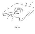
FIG. 4 is a perspective view of a slicing cassette according to one embodiment of the invention. -
FIG. 5 is a perspective view of a shredding cassette according to one embodiment of the invention. -
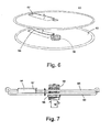
FIG. 6 is a partial exploded view of an adjustable slicing cassette according to one embodiment of the invention, with the outer housing removed. -
FIG. 7 is a partial side view of the adjustable slicing cassette ofFig. 6 , with the out housing removed. -
FIG. 8A is a perspective view of a first cutting cassette according to one embodiment of the invention. -
FIG. 8B is a perspective view of a second cutting cassette according to one embodiment of the invention. -
FIG. 1 illustrates one embodiment of afood processor 10 according to the invention. Thefood processor 10 described herein shares some features of a traditional food processor, and will not be described in detail except as necessary for a complete understanding of the invention. - The
food processor 10 may be illustrated comprising ahousing 12, which may include auser interface 18 that hasoperator controls 20, such as a dial(s) and/or switch(es), to enable a user to control the operation of thefood processor 10. The top of themain housing 12 is closed by ahousing cover 34, which may be removably secured to themain housing 12 by a snap fit, a twist lock arrangement, or any other suitable means of attachment. Thehousing cover 34 is illustrated as being transparent, but need not be. - The
housing cover 34 includes afeed tube 36, which is formed into and extends upwardly from thehousing cover 34. Thefeed tube 36 forms an inlet to afood processing path 37 extending through thehousing 12. - A
food pusher 38 is provided to push food down thefeed tube 36. A stop, in the form offlange 39, is provided on thefood pusher 38 to limit the insertion of thefood pusher 38 into thefeed tube 36. - One or more food processing tools, generically referred to by
numeral 60, are received withincorresponding slots 50 provided in the face of thehousing 12 to place the food processing tool within thefood processing path 37 where thefood processing tools 58 may aid in processing food. With this configuration, thefood processing tools 58 may be selectively inserted and removed from theslots 50 to provide the user with the ability to control and combine their functionality to obtain the desired food processing in a single pass of the food through thefood processing path 37. - The
housing 12 may also include one or more openings, which are illustrated asslots 50. In the illustrated embodiment, threeslots 50 are shown, however, more or fewer slots may be provided. Theslot 50 provides an opening in which to insert afood processing tool 58. Further, theslot 50 can be sized to receive at least one or a multiplicity offood processing tools 58 in asingle slot 50. - The
housing 12 further includes arecess 52 in the lower portion of thehousing 12, which is in alignment with thefood processing path 37. The user may place abowl 54 in therecess 52 to collect the processed food. Thebowl 54 is not integral to thefood processor 10 and may be of any size and shape which fits within therecess 52. - Referring to
Fig. 2 , the entirefood processing path 37 may be seen. As illustrated, thefood processing path 37 has ahousing portion 53 that extends between thefeed tube 36 to therecess 52. Theslots 50 intersect with thefood processing path 37 such that thefood processing tools 58 extend into thefood processing path 37. - The
food processor 10 further comprises a drive system operably coupled to thefood processing tools 58 to drive the tools as needed to process the food. The drive system as illustrated comprises amotor 14 and agear system 25. The gear system is operably coupled to themotor 14 and engages thefood processing tools 58 when they are received within theslots 50. - An
exemplary gear system 25 comprises adrive shaft 24 extending out of themotor 14 and anoutput gear 26 mounted to thedrive shaft 24. As illustrated, there is anoutput gear 26 for each of theslots 50, which provides for driving anyfood processing tool 58 inserted into thecorresponding slot 50. Thedrive shaft 24 andoutput gear 26 may be of any known gearing system, for example a planetary gear system, spur gear system, or any other suitable gearing system. For example, theoutput gears 26 may comprise one or more gears to effect a different gear reduction, which is useful when the differentfood processing tools 58 must be driven at different rates. - The
food processor 10 comprises a control system operably coupled to themotor 14 to enable actuation of themotor 14. The control system as illustrated comprises acontroller 16, which is electrically coupled through auser interface lead 22 to theoperator controls 20. Themotor 14 may be electrically coupled throughlead 28 to thecontroller 16, or may be wirelessly coupled. - In operation, the user may selectively insert the
food processing tools 58 into theslots 50 and place thebowl 54 in therecess 52. The food to be processed is placed in thefeed tube 36 and thefood pusher 38 is inserted into thefeed tube 36. Power to thefood processor 10 is turned on via theoperator controls 20, which actuates themotor 14. Themotor 14 drives thegear system 25, which, in turn, drives thefood processing tools 58 to process the food. - The food is pushed by the
food pusher 38 down thefood processing path 37. As the food progresses down thefood processing path 37, it passes through the installedfood processing tools 58, which process the food according to the functionality of the specificfood processing tool 58, which may, for illustrative purposes, include slicing, shredding, cubing or other. After the food passes through the installedfood processing tools 58, the processed food falls into thebowl 54 to be collected. - Having multiple
food processing tools 58 located within thefood path 37 provides for sequentially applying the functionality from multiplefood processing tools 58 in a single pass of the food. This structure provides flexibility and functionality that has not previously been obtainable by food processors. The user may mix and match the differentfood processing tools 58 to obtain processing functionality that was previously not possible. - Referring to
FIG. 3 , according to one embodiment of the present invention, thefood pusher 38 may also be designed to provide automatic functionality to push the food down thefood processing path 37, instead of relying on the user to manually push thefood pusher 38.Fig. 3 illustrates an exemplary means of providing automatic functionality of thefood pusher 38 is through utilization of thegear system 25. Agear track 40 may be located on the exterior of thefood pusher 38. The teeth on thefood pusher 38gear track 40 mesh with ascrew drive 44 that extends up into thefeed tube 36. Thescrew drive 44 is driven by anoutput gear 46 that is engaged with themain drive shaft 24. Thescrew drive 44 meshes with both theoutput gear 46 and thegear track 40, and the rotation of thescrew drive 44 is translated into linear motion of thegear track 40, pulling thefood pusher 38 down. Alternatively, thescrew drive 44 may be driven by a secondary motor (not shown). As another alternative, thefood pusher 38 may be manually operated by disabling thescrew drive 44. -
FIGS. 4-8 illustrate exemplary food processing tools that may be used for the previously identifiedfood processing tools 58. As illustrated, the exemplary food processing tools comprise a plurality of cassettes for performing various food processing tasks, such as slicing, shredding, cubing, and forming "sticks". These cassettes can be inserted into the providedslots 50 as desired by the user. - Referring to
FIG. 4 , the first exemplaryfood processing tool 58 is a slicingcassette 60, which slices the food to be processed. As illustrated, the slicingcassette 60 comprises ahousing 62 that encloses arotating slicing disc 63, which includes aslicing blade 64 and a cassette gear 66 (shown inFig. 2 ). Thehousing 62 has a cutaway that exposes only a portion of theslicing disc 63, limiting theslicing blade 64 to slicing the food when theslicing blade 64 passes by the cutaway. The gear 66 (not shown) may be attached by any suitable means to theslicing disc 63 and is axially located at the center of theslicing disc 63, within thehousing 62. As shown inFIG. 2 , when the slicingcassette 60 is inserted into the providedslot 50, thecassette gear 66 meshes with theoutput gear 26. Therefore, themotor 14 drives the rotation of theslicing disc 63 andslicing blade 64 via thedrive shaft 24,output gear 26, andcassette gear 66. The torque and speed of theslicing disc 63 can be controlled via themotor 14 and/or the gearing ratios. - Referring to
FIG. 5 , the second exemplary food processing tool is a shreddingcassette 70, which shreds the food to be processed. Like the slicingcassette 60, the shreddingcassette 70 consists of ahousing 72 that encloses arotating shredding disc 74 that includes a cassette gear 66 (not shown) and at least one shreddingport 76, or as illustrated, a plurality of shreddingports 76. Thehousing 72 has a cutaway that exposes only a portion of theshredding disc 74, limiting the shreddingports 76 to shredding the food when the shreddingports 76 pass by the cutaway. The gear 66 (not shown) may be attached by any suitable means, to theshredding disc 74 and is axially located at the center of theshredding disc 74, within thehousing 72. As shown inFIG. 2 , when the shreddingcassette 70 is inserted into the providedslot 50, thecassette gear 66 meshes with theoutput gear 26. Therefore, themotor 14 drives the rotation of theshredding disc 74 and shreddingports 76 via thedrive shaft 24,output gear 26, andcassette gear 66. The torque and speed of theshredding disc 74 can be controlled via themotor 14 and/or the gearing ratios. - Referring to
FIGS. 6 and 7 , in another embodiment of the invention, the thickness of the sliced or shredded food can be varied, wherein the thickness is a function of the relative spacing between the discs and is described herein as the bite of the cutting element. This embodiment can be utilized on both the slicingcassette 60 and the shreddingcassette 70, but will be described and illustrated herein with reference to the slicingcassette 60, with thehousing 72 removed for clarity. One exemplary means in which the thickness of the sliced food can be varied may be accomplished by adding afood support disc 65 on top of theslicing disc 63. When thefood support disc 65 andslicing disc 63 are coupled together, theslicing blade 64 may protrude through acutout 67 in thefood support disc 65. The thickness of the slice may be varied by adjusting the position of theslicing disc 63 with respect to the surface of thefood support disc 65. The vertical position of theslicing disc 63 may be adjusted by means of a screw system which raises and lowers theslicing disc 63. The screw system may include a simple threadedshaft 68, along which the threadedslicing disc 63 may be translated up or down. However, other methods of adjusting theslicing disc 63 relative to thefood support disc 65 are possible, for example, an automatic adjustment. To obtain a thicker slice of food, theslicing disc 63 may be adjusted to increase the space between the slicingblade 64 and the surface of thefood support disc 65. Oppositely, to obtain a thinner slice of food, theslicing blade 64 may be adjusted closer to the surface of thefood support disc 65. Examples of foods the user may make using the slicingcassette 60 include potato slices or orange slices. As mentioned above, the size of the shred may be adjusted within the shreddingcassette 70 in a similar fashion. - Referring to
FIG. 8A , the third exemplary food processing tool is a cuttingcassette 80, which cuts the food to be processed. The cuttingcassette 80 consists of aframe 81 circumscribing a plurality of spacedblades 86 or cutting wires, the cutting planes of theblades 86 may be vertical or slightly angled. Unlike the slicingcassette 60 and shreddingcassette 70, the cuttingcassette 80 is not rotated, and therefore does not include acassette gear 66 by which to be driven by themotor 14. - Like the cutting
cassette 80, the fourth food processing tool, shown inFIG. 8B , is asecond cutting cassette 82, which also cuts the food to be processed. Thesecond cutting cassette 82 consists of a frame 84 circumscribing a plurality of spacedblades 88, the cutting planes of which may be vertical or slightly angled. The difference between the cuttingcassette 80 and thesecond cutting cassette 82 is that the second set ofblades 88 is orthogonal to the first set ofblades 86. Thesecond cutting cassette 82 is not rotated either, and therefore does not include acassette gear 66. - The cutting
cassette 80 and second cuttingcassette 82 can be used separately or together. If each is inserted into the providedslots 50 and used together, when viewed from a top-view, the two sets ofblades - In another embodiment of the invention, the thickness of the cut of food may be varied, or when using the cutting
cassettes cassettes adjustment screw 90. Theblades frame 81, 84, and through a hole (not shown) in each blade, may be meshed with theadjustment screw 90. Theadjustment screw 90 may be provided with aknob 92 by which the user can turn theadjustment screw 90. Turning theadjustment screw 90 may increase or decrease the spacing between theindividual blades adjustment screw 90 is turned to spread theblades excess cutting blades adjustment screw 90, out of thefood processing path 37. The opposite action may be taken to adjust theblades - Further, the first and
second cutting cassettes meshed cassettes orthogonal cutting blades - Together, the cutting
cassette 80 and second cuttingcassette 82 may be used in combination with the slicingcassette 60 described above to form cubes of food. As described above, the cuttingcassette 80 and second cuttingcassette 82 together form a cutting grid. If the user desires to make cubed food, thecassettes slots 50 and the slicingcassette 60 may be inserted into thelower slot 50. Food sticks are formed after the food passes through the first twocassettes slicing blade 64 of the slicingcassette 60 cuts the stick at a desired length, or specifically, into cubes. The length of the stick may be set by adjusting the vertical position of theslicing disc 63 as described above. Cubes may be cut by setting equal spacing between theblades cassettes slicing blade 64 of the slicingcassette 60. An example of a food the user may make using the combination of the cuttingcassette 80, second cuttingcassette 82, and slicingcassette 60 includes cheese cubes. - The speed of rotation, or processing, for each of the
food processing tools 58 can be independently set. One way in which this may be accomplished is through the design of the gear ratios of eachfood processing tool 58. Thecassette gear 66 on each of thefood processing tools 58 can be provided with more or fewer teeth, in relation to thedrive shaft 24, as is conventional. This enables thefood processor 10 to utilize onedrive shaft 24, yet output different rotation speeds for each of the installedfood processing tools 58. The speed of thedrive shaft 24, and therefore thefood processing tools 58, may also be varied by adjusting the speed of themotor 14. - Utilizing the
multiple slots 50 andfood processing tools 58, the user is able to make various combinations, resulting in different sizes and shapes of processed foods. Different processed foods can be formed by inserting thefood processing tools 58 intodifferent slots 50, using differing combinations offood processing tools 58, and/or adjusting the spacing of the cutting blades of each of thefood processing tools 58. - The device of the present invention offers many benefits to consumers, including the ability to automatically process food cubes. The
food processor 10 eliminates the need for the user to cut cubes of food by hand and provides improved variability in the functionality as compared to a standard food processor. Thisfood processor 10 also reduces the number of food processing tools required to slice, shred, or cut food by providing adjustable cassettes, enabling various processed food size. Conventionally, to change the size of the processed food, multiple food processing tools are needed for each function.
Claims (15)
- A food processor (10) comprising:a housing (12) defining a food processing path (37); at least one slot (50) formed in the face of the housing (12) and extending into the food processing path (37); at least one food processing tool (58) removably received within the slot (50) such that food passing along the food processing path (37) is processed by the tool (58); and a drive system operably coupled to the food processing tool (58) to drive the food processing tool (58) as needed to process the food, the drive system comprising a motor (14), characterized in that the drive system comprises a gear system (25) operably coupled to the motor (14) and engaging the food processing tool (58) when received within the slot (50).
- The food processor according to claim 1 further comprising multiple food processing tools (58) which may be selectively received within the at least one slot (50).
- The food processor according to claim 2 further comprising multiple slots (50) wherein each slot may receive one of the food processing tools (58) such that the food passing through the food processing path (37) is processed according to each of the food processing tools (58) received within the slots.
- The food processor according to claim 3 wherein at least some of the multiple food processing tools (58) perform a different food processing function.
- The food processor according to claim 3 wherein the multiple food processing tools (58) comprise at least two of: shredding tool (74), slicing tool (63), and a cutting tool.
- The food processor according to claim 3 wherein the multiple food processing tools (58) comprise at least two cutting tools.
- The food processor according to claim 6 wherein each of the at least two cutting tools have cutting elements and the cutting elements of each tool are arranged along different planes.
- The food processor according to claim 7 wherein the planes are orthogonal to each other to collectively form a cubing tool.
- The food processor according to claim 1 further comprising a cassette sized to be slidably received within the slot (50) and in which the food processing tool (58) is mounted.
- The food processor according to claim 9 wherein the food processing tool comprises first and second discs, which are relatively movable to each other, with one of the discs having a cutting element, wherein the relative movement of the discs adjusts the bite of the cutting element.
- The food processor according to claim 9 wherein the discs are rotatably mounted within the cassette.
- The food processor according to claim 1 further comprising a food pusher (38) receivable in the food path (37) and a drive system operably coupled to the food pusher to drive the food pusher along the path (37) to force food along the path.
- The food processor according to claim 1 further comprising a plurality of food processing cassettes (60, 70, 80, 82) sized for receipt within at least one slot (50) and in which the food processing tool (58) is mounted.
- The food processor according to claim 13 further comprising a drive system operably coupled to at least one of the food pusher (38) along the path to force food along the path and one of the plurality of cassettes (60, 70, 80, 82) to drive the corresponding processing tool (58) when the one of the plurality of cassettes is received within the slot.
- The food processor according to claim 14 wherein the processing tool (58) of at least some of the plurality of cassettes is rotatably mounted within the corresponding cassette and the drive system rotates the rotatably mounted tool.
Priority Applications (1)
| Application Number | Priority Date | Filing Date | Title |
|---|---|---|---|
| PL09162005T PL2130471T3 (en) | 2008-06-06 | 2009-06-05 | Household food processor with food processing tools |
Applications Claiming Priority (2)
| Application Number | Priority Date | Filing Date | Title |
|---|---|---|---|
| US5927908P | 2008-06-06 | 2008-06-06 | |
| US12/477,976 US8215231B2 (en) | 2008-06-06 | 2009-06-04 | Household food processor with food processing tools |
Publications (2)
| Publication Number | Publication Date |
|---|---|
| EP2130471A1 EP2130471A1 (en) | 2009-12-09 |
| EP2130471B1 true EP2130471B1 (en) | 2013-07-24 |
Family
ID=41000048
Family Applications (1)
| Application Number | Title | Priority Date | Filing Date |
|---|---|---|---|
| EP20090162005 Not-in-force EP2130471B1 (en) | 2008-06-06 | 2009-06-05 | Household food processor with food processing tools |
Country Status (4)
| Country | Link |
|---|---|
| US (1) | US8215231B2 (en) |
| EP (1) | EP2130471B1 (en) |
| ES (1) | ES2425425T3 (en) |
| PL (1) | PL2130471T3 (en) |
Cited By (1)
| Publication number | Priority date | Publication date | Assignee | Title |
|---|---|---|---|---|
| WO2016101157A1 (en) * | 2014-12-24 | 2016-06-30 | Whirlpool Corporation | Modified dicing procedure for a food processor |
Families Citing this family (20)
| Publication number | Priority date | Publication date | Assignee | Title |
|---|---|---|---|---|
| WO2006123368A1 (en) * | 2005-05-19 | 2006-11-23 | Marel Hf. | Portioning of food stuff |
| US8671832B2 (en) * | 2009-12-10 | 2014-03-18 | Whirlpool Corporation | Food processor with an external control for adjusting cutting thickness |
| FR2959154B1 (en) * | 2010-04-22 | 2012-09-07 | Hameur Sa | VEGETABLE CUTTER DEVICE |
| WO2012113106A1 (en) | 2011-02-25 | 2012-08-30 | Whirlpool Corporation | A food processing device with an externally operated adjustment mechanism |
| US8720325B2 (en) | 2010-04-29 | 2014-05-13 | Whirlpool Corporation | Food processor with a lockable adjustable blade assembly |
| US10449685B2 (en) | 2010-04-29 | 2019-10-22 | Whirlpool Corporation | Food processor with adjustable blade assembly |
| US9049965B2 (en) | 2011-02-25 | 2015-06-09 | Whirlpool Corporation | Food processing device with an externally operated adjustment mechanism |
| WO2012113107A1 (en) | 2011-02-25 | 2012-08-30 | Whirlpool Corporation | Food processing device with control buttons mounted on lid |
| EP2564743A1 (en) | 2011-09-01 | 2013-03-06 | Koninklijke Philips Electronics N.V. | An apparatus and method for processing a food stuff |
| US8905342B2 (en) | 2011-11-30 | 2014-12-09 | Whirlpool Corporation | Food processing device with lid mounted adjustment mechanism |
| US8814072B2 (en) * | 2011-11-30 | 2014-08-26 | Whirlpool Corporation | User-controlled adjustment mechanism for a food processing device |
| US8899504B2 (en) | 2011-11-30 | 2014-12-02 | Whirlpool Corporation | Externally-operated adjustment mechanism for a food processing device |
| US8833683B2 (en) | 2012-03-08 | 2014-09-16 | Whirlpool Corporation | Food processor with external control for operating an adjustable cutting tool |
| US9522399B2 (en) * | 2012-03-09 | 2016-12-20 | Whirlpool Corporation | Food processor and adjustable cutting assembly |
| US9439539B2 (en) | 2012-10-18 | 2016-09-13 | Whirlpool Corporation | Dicing tool for domestic food processing device |
| FR2999902B1 (en) * | 2012-12-21 | 2015-02-27 | Seb Sa | CULINARY PREPARATION APPARATUS WITH STORAGE HOLDER FOR REMOVABLE WORK ACCESSORIES |
| ITUA20163246A1 (en) * | 2016-05-09 | 2017-11-09 | Turatti Srl | Wire cutting machine. |
| WO2017205471A1 (en) * | 2016-05-25 | 2017-11-30 | Sharkninja Operating Llc | Oscillating blade for food processor system |
| US10695935B2 (en) | 2016-08-11 | 2020-06-30 | Conair Corporation | Slicing disc assembly for food processor |
| WO2018183912A1 (en) * | 2017-03-30 | 2018-10-04 | Klein Zalman D | Mechanized cubing apparatus |
Citations (2)
| Publication number | Priority date | Publication date | Assignee | Title |
|---|---|---|---|---|
| US4062260A (en) * | 1976-09-15 | 1977-12-13 | John Steinhogl | Produce cutter |
| GB2171462A (en) * | 1984-12-10 | 1986-08-28 | John Gilbert Green | Food extruding device |
Family Cites Families (18)
| Publication number | Priority date | Publication date | Assignee | Title |
|---|---|---|---|---|
| GB132809A (en) | ||||
| US2563237A (en) * | 1947-06-02 | 1951-08-07 | Grocoff William | Butter cutter |
| GB658717A (en) | 1948-06-16 | 1951-10-10 | Johannes Schwarz | Improvements in or relating to appliances for domestic use in the preparation of food |
| BE668304A (en) * | 1964-08-31 | 1900-01-01 | ||
| FR2109032A5 (en) * | 1970-04-09 | 1972-05-26 | Brignard Francois | |
| US3664396A (en) * | 1971-01-04 | 1972-05-23 | Gerard A Tremblay | Dicing machine |
| US4095339A (en) * | 1977-02-17 | 1978-06-20 | Rose Turner | Egg slicer |
| CA2006822A1 (en) | 1989-04-19 | 1990-10-19 | John W. Mcclean | Portable food processor (a) |
| US5163362A (en) * | 1991-09-20 | 1992-11-17 | Better Mousetraps, Inc. | Food press |
| US5478018A (en) * | 1994-09-21 | 1995-12-26 | Wang; Kuang-Pin | Food processing device |
| US5692424A (en) * | 1996-01-03 | 1997-12-02 | Wallace; Stephen C. | Food slicer |
| USD421363S (en) * | 1998-01-05 | 2000-03-07 | Conair Corporation | Continuous feed food processor |
| CN2456604Y (en) * | 2000-10-26 | 2001-10-31 | 汪恩光 | Multifunction planing and pressing machine |
| SE0202759L (en) * | 2002-09-17 | 2003-06-24 | Haellde Maskiner Ab | Food preparation device |
| ATE415258T1 (en) * | 2002-12-19 | 2008-12-15 | Urschel Lab Inc | FOOD CUTTING APPARATUS AND METHOD |
| US7900544B2 (en) * | 2005-11-03 | 2011-03-08 | Williams Collis H | Combination food preparation device |
| CN2868134Y (en) * | 2005-12-29 | 2007-02-14 | 陈松威 | Manual food treater |
| US20070252024A1 (en) * | 2006-03-07 | 2007-11-01 | Barraclough James R | Reciprocating blade and circumferentially driven blade food preparation device |
-
2009
- 2009-06-04 US US12/477,976 patent/US8215231B2/en active Active
- 2009-06-05 PL PL09162005T patent/PL2130471T3/en unknown
- 2009-06-05 EP EP20090162005 patent/EP2130471B1/en not_active Not-in-force
- 2009-06-05 ES ES09162005T patent/ES2425425T3/en active Active
Patent Citations (2)
| Publication number | Priority date | Publication date | Assignee | Title |
|---|---|---|---|---|
| US4062260A (en) * | 1976-09-15 | 1977-12-13 | John Steinhogl | Produce cutter |
| GB2171462A (en) * | 1984-12-10 | 1986-08-28 | John Gilbert Green | Food extruding device |
Cited By (3)
| Publication number | Priority date | Publication date | Assignee | Title |
|---|---|---|---|---|
| WO2016101157A1 (en) * | 2014-12-24 | 2016-06-30 | Whirlpool Corporation | Modified dicing procedure for a food processor |
| EP3236814A4 (en) * | 2014-12-24 | 2018-08-29 | Whirlpool Corporation | Modified dicing procedure for a food processor |
| US10092138B2 (en) | 2014-12-24 | 2018-10-09 | Whirlpool Corporation | Modified dicing procedure for a food processor |
Also Published As
| Publication number | Publication date |
|---|---|
| US8215231B2 (en) | 2012-07-10 |
| ES2425425T3 (en) | 2013-10-15 |
| US20090301319A1 (en) | 2009-12-10 |
| PL2130471T3 (en) | 2013-10-31 |
| EP2130471A1 (en) | 2009-12-09 |
Similar Documents
| Publication | Publication Date | Title |
|---|---|---|
| EP2130471B1 (en) | Household food processor with food processing tools | |
| EP2677909B1 (en) | A food processing device with an externally operated adjustment mechanism | |
| AU2013201466B2 (en) | Food processor and adjustable cutting assembly | |
| AU2012258371B2 (en) | Food processing device with a lid mounted adjustment mechanism | |
| US9049965B2 (en) | Food processing device with an externally operated adjustment mechanism | |
| EP2599416B1 (en) | Externally-operated adjustment mechanism for a food processing device | |
| CN105835114A (en) | Full-automatic vegetable slicing and shredding device | |
| US10821620B2 (en) | Adjustable vegetable food machine | |
| CN106393232A (en) | Food processer capable of cutting out continuous long strips or continuous long sheets | |
| CN218285723U (en) | Kitchen cutting and matching machine | |
| JP4453065B2 (en) | Food shredder | |
| JPH0630392Y2 (en) | Food processor | |
| CN217345694U (en) | Multifunctional kitchen vegetable cutter | |
| JP4539767B2 (en) | Burdock crusher | |
| KR20160040769A (en) | Easily adjusted auto vegetable cutting machine | |
| KR200146265Y1 (en) | The cutter for vegetables | |
| CN207888730U (en) | A kind of small-sized household food slicer | |
| KR20190063612A (en) | Slice thickness adjusting device for cutter | |
| JPS6035451Y2 (en) | Equipment for cooking vegetables, etc. | |
| CN108175308A (en) | A kind of electric fruit-vegetable cooking machine | |
| KR20160001784U (en) | Equipment of Replace the Slice Kitchen knife by the axis turning | |
| KR19990066663A (en) | Seasoning food shredding device | |
| JPS6322958B2 (en) |
Legal Events
| Date | Code | Title | Description |
|---|---|---|---|
| PUAI | Public reference made under article 153(3) epc to a published international application that has entered the european phase |
Free format text: ORIGINAL CODE: 0009012 |
|
| AK | Designated contracting states |
Kind code of ref document: A1 Designated state(s): AT BE BG CH CY CZ DE DK EE ES FI FR GB GR HR HU IE IS IT LI LT LU LV MC MK MT NL NO PL PT RO SE SI SK TR |
|
| 17P | Request for examination filed |
Effective date: 20100505 |
|
| 17Q | First examination report despatched |
Effective date: 20100610 |
|
| GRAP | Despatch of communication of intention to grant a patent |
Free format text: ORIGINAL CODE: EPIDOSNIGR1 |
|
| INTG | Intention to grant announced |
Effective date: 20130430 |
|
| GRAS | Grant fee paid |
Free format text: ORIGINAL CODE: EPIDOSNIGR3 |
|
| GRAA | (expected) grant |
Free format text: ORIGINAL CODE: 0009210 |
|
| RIN1 | Information on inventor provided before grant (corrected) |
Inventor name: MCCORMICK, ARREN J. Inventor name: GUSHWA, DAVID J. Inventor name: CONTI, MICHAEL P. Inventor name: SHAO, BEN C. Inventor name: WESSEL, JEFFREY A. Inventor name: BIGGE, WILLIAM J. |
|
| AK | Designated contracting states |
Kind code of ref document: B1 Designated state(s): AT BE BG CH CY CZ DE DK EE ES FI FR GB GR HR HU IE IS IT LI LT LU LV MC MK MT NL NO PL PT RO SE SI SK TR |
|
| REG | Reference to a national code |
Ref country code: GB Ref legal event code: FG4D |
|
| REG | Reference to a national code |
Ref country code: CH Ref legal event code: EP |
|
| REG | Reference to a national code |
Ref country code: AT Ref legal event code: REF Ref document number: 622899 Country of ref document: AT Kind code of ref document: T Effective date: 20130815 |
|
| REG | Reference to a national code |
Ref country code: IE Ref legal event code: FG4D |
|
| REG | Reference to a national code |
Ref country code: DE Ref legal event code: R096 Ref document number: 602009017355 Country of ref document: DE Effective date: 20130919 |
|
| REG | Reference to a national code |
Ref country code: ES Ref legal event code: FG2A Ref document number: 2425425 Country of ref document: ES Kind code of ref document: T3 Effective date: 20131015 |
|
| REG | Reference to a national code |
Ref country code: PL Ref legal event code: T3 |
|
| REG | Reference to a national code |
Ref country code: AT Ref legal event code: MK05 Ref document number: 622899 Country of ref document: AT Kind code of ref document: T Effective date: 20130724 |
|
| REG | Reference to a national code |
Ref country code: NL Ref legal event code: VDEP Effective date: 20130724 |
|
| REG | Reference to a national code |
Ref country code: LT Ref legal event code: MG4D |
|
| PG25 | Lapsed in a contracting state [announced via postgrant information from national office to epo] |
Ref country code: LT Free format text: LAPSE BECAUSE OF FAILURE TO SUBMIT A TRANSLATION OF THE DESCRIPTION OR TO PAY THE FEE WITHIN THE PRESCRIBED TIME-LIMIT Effective date: 20130724 Ref country code: NO Free format text: LAPSE BECAUSE OF FAILURE TO SUBMIT A TRANSLATION OF THE DESCRIPTION OR TO PAY THE FEE WITHIN THE PRESCRIBED TIME-LIMIT Effective date: 20131024 Ref country code: SE Free format text: LAPSE BECAUSE OF FAILURE TO SUBMIT A TRANSLATION OF THE DESCRIPTION OR TO PAY THE FEE WITHIN THE PRESCRIBED TIME-LIMIT Effective date: 20130724 Ref country code: BE Free format text: LAPSE BECAUSE OF FAILURE TO SUBMIT A TRANSLATION OF THE DESCRIPTION OR TO PAY THE FEE WITHIN THE PRESCRIBED TIME-LIMIT Effective date: 20130724 Ref country code: PT Free format text: LAPSE BECAUSE OF FAILURE TO SUBMIT A TRANSLATION OF THE DESCRIPTION OR TO PAY THE FEE WITHIN THE PRESCRIBED TIME-LIMIT Effective date: 20131125 Ref country code: HR Free format text: LAPSE BECAUSE OF FAILURE TO SUBMIT A TRANSLATION OF THE DESCRIPTION OR TO PAY THE FEE WITHIN THE PRESCRIBED TIME-LIMIT Effective date: 20130724 Ref country code: IS Free format text: LAPSE BECAUSE OF FAILURE TO SUBMIT A TRANSLATION OF THE DESCRIPTION OR TO PAY THE FEE WITHIN THE PRESCRIBED TIME-LIMIT Effective date: 20131124 Ref country code: AT Free format text: LAPSE BECAUSE OF FAILURE TO SUBMIT A TRANSLATION OF THE DESCRIPTION OR TO PAY THE FEE WITHIN THE PRESCRIBED TIME-LIMIT Effective date: 20130724 Ref country code: CY Free format text: LAPSE BECAUSE OF FAILURE TO SUBMIT A TRANSLATION OF THE DESCRIPTION OR TO PAY THE FEE WITHIN THE PRESCRIBED TIME-LIMIT Effective date: 20130814 |
|
| PG25 | Lapsed in a contracting state [announced via postgrant information from national office to epo] |
Ref country code: NL Free format text: LAPSE BECAUSE OF FAILURE TO SUBMIT A TRANSLATION OF THE DESCRIPTION OR TO PAY THE FEE WITHIN THE PRESCRIBED TIME-LIMIT Effective date: 20130724 Ref country code: LV Free format text: LAPSE BECAUSE OF FAILURE TO SUBMIT A TRANSLATION OF THE DESCRIPTION OR TO PAY THE FEE WITHIN THE PRESCRIBED TIME-LIMIT Effective date: 20130724 Ref country code: SI Free format text: LAPSE BECAUSE OF FAILURE TO SUBMIT A TRANSLATION OF THE DESCRIPTION OR TO PAY THE FEE WITHIN THE PRESCRIBED TIME-LIMIT Effective date: 20130724 Ref country code: GR Free format text: LAPSE BECAUSE OF FAILURE TO SUBMIT A TRANSLATION OF THE DESCRIPTION OR TO PAY THE FEE WITHIN THE PRESCRIBED TIME-LIMIT Effective date: 20131025 Ref country code: FI Free format text: LAPSE BECAUSE OF FAILURE TO SUBMIT A TRANSLATION OF THE DESCRIPTION OR TO PAY THE FEE WITHIN THE PRESCRIBED TIME-LIMIT Effective date: 20130724 |
|
| PG25 | Lapsed in a contracting state [announced via postgrant information from national office to epo] |
Ref country code: CY Free format text: LAPSE BECAUSE OF FAILURE TO SUBMIT A TRANSLATION OF THE DESCRIPTION OR TO PAY THE FEE WITHIN THE PRESCRIBED TIME-LIMIT Effective date: 20130724 |
|
| PG25 | Lapsed in a contracting state [announced via postgrant information from national office to epo] |
Ref country code: CZ Free format text: LAPSE BECAUSE OF FAILURE TO SUBMIT A TRANSLATION OF THE DESCRIPTION OR TO PAY THE FEE WITHIN THE PRESCRIBED TIME-LIMIT Effective date: 20130724 Ref country code: DK Free format text: LAPSE BECAUSE OF FAILURE TO SUBMIT A TRANSLATION OF THE DESCRIPTION OR TO PAY THE FEE WITHIN THE PRESCRIBED TIME-LIMIT Effective date: 20130724 Ref country code: RO Free format text: LAPSE BECAUSE OF FAILURE TO SUBMIT A TRANSLATION OF THE DESCRIPTION OR TO PAY THE FEE WITHIN THE PRESCRIBED TIME-LIMIT Effective date: 20130724 Ref country code: EE Free format text: LAPSE BECAUSE OF FAILURE TO SUBMIT A TRANSLATION OF THE DESCRIPTION OR TO PAY THE FEE WITHIN THE PRESCRIBED TIME-LIMIT Effective date: 20130724 Ref country code: SK Free format text: LAPSE BECAUSE OF FAILURE TO SUBMIT A TRANSLATION OF THE DESCRIPTION OR TO PAY THE FEE WITHIN THE PRESCRIBED TIME-LIMIT Effective date: 20130724 |
|
| PLBE | No opposition filed within time limit |
Free format text: ORIGINAL CODE: 0009261 |
|
| STAA | Information on the status of an ep patent application or granted ep patent |
Free format text: STATUS: NO OPPOSITION FILED WITHIN TIME LIMIT |
|
| 26N | No opposition filed |
Effective date: 20140425 |
|
| REG | Reference to a national code |
Ref country code: DE Ref legal event code: R097 Ref document number: 602009017355 Country of ref document: DE Effective date: 20140425 |
|
| PG25 | Lapsed in a contracting state [announced via postgrant information from national office to epo] |
Ref country code: LU Free format text: LAPSE BECAUSE OF FAILURE TO SUBMIT A TRANSLATION OF THE DESCRIPTION OR TO PAY THE FEE WITHIN THE PRESCRIBED TIME-LIMIT Effective date: 20140605 Ref country code: MC Free format text: LAPSE BECAUSE OF FAILURE TO SUBMIT A TRANSLATION OF THE DESCRIPTION OR TO PAY THE FEE WITHIN THE PRESCRIBED TIME-LIMIT Effective date: 20130724 |
|
| REG | Reference to a national code |
Ref country code: CH Ref legal event code: PL |
|
| REG | Reference to a national code |
Ref country code: IE Ref legal event code: MM4A |
|
| PG25 | Lapsed in a contracting state [announced via postgrant information from national office to epo] |
Ref country code: LI Free format text: LAPSE BECAUSE OF NON-PAYMENT OF DUE FEES Effective date: 20140630 Ref country code: IE Free format text: LAPSE BECAUSE OF NON-PAYMENT OF DUE FEES Effective date: 20140605 Ref country code: CH Free format text: LAPSE BECAUSE OF NON-PAYMENT OF DUE FEES Effective date: 20140630 |
|
| PG25 | Lapsed in a contracting state [announced via postgrant information from national office to epo] |
Ref country code: MT Free format text: LAPSE BECAUSE OF FAILURE TO SUBMIT A TRANSLATION OF THE DESCRIPTION OR TO PAY THE FEE WITHIN THE PRESCRIBED TIME-LIMIT Effective date: 20130724 |
|
| REG | Reference to a national code |
Ref country code: FR Ref legal event code: PLFP Year of fee payment: 8 |
|
| PGFP | Annual fee paid to national office [announced via postgrant information from national office to epo] |
Ref country code: PL Payment date: 20160315 Year of fee payment: 8 |
|
| PG25 | Lapsed in a contracting state [announced via postgrant information from national office to epo] |
Ref country code: BG Free format text: LAPSE BECAUSE OF FAILURE TO SUBMIT A TRANSLATION OF THE DESCRIPTION OR TO PAY THE FEE WITHIN THE PRESCRIBED TIME-LIMIT Effective date: 20130724 |
|
| PG25 | Lapsed in a contracting state [announced via postgrant information from national office to epo] |
Ref country code: HU Free format text: LAPSE BECAUSE OF FAILURE TO SUBMIT A TRANSLATION OF THE DESCRIPTION OR TO PAY THE FEE WITHIN THE PRESCRIBED TIME-LIMIT; INVALID AB INITIO Effective date: 20090605 Ref country code: TR Free format text: LAPSE BECAUSE OF FAILURE TO SUBMIT A TRANSLATION OF THE DESCRIPTION OR TO PAY THE FEE WITHIN THE PRESCRIBED TIME-LIMIT Effective date: 20130724 |
|
| PGFP | Annual fee paid to national office [announced via postgrant information from national office to epo] |
Ref country code: GB Payment date: 20160601 Year of fee payment: 8 Ref country code: DE Payment date: 20160601 Year of fee payment: 8 Ref country code: ES Payment date: 20160511 Year of fee payment: 8 |
|
| PGFP | Annual fee paid to national office [announced via postgrant information from national office to epo] |
Ref country code: FR Payment date: 20160516 Year of fee payment: 8 |
|
| PGFP | Annual fee paid to national office [announced via postgrant information from national office to epo] |
Ref country code: IT Payment date: 20160621 Year of fee payment: 8 |
|
| REG | Reference to a national code |
Ref country code: DE Ref legal event code: R119 Ref document number: 602009017355 Country of ref document: DE |
|
| GBPC | Gb: european patent ceased through non-payment of renewal fee |
Effective date: 20170605 |
|
| REG | Reference to a national code |
Ref country code: FR Ref legal event code: ST Effective date: 20180228 |
|
| PG25 | Lapsed in a contracting state [announced via postgrant information from national office to epo] |
Ref country code: DE Free format text: LAPSE BECAUSE OF NON-PAYMENT OF DUE FEES Effective date: 20180103 Ref country code: GB Free format text: LAPSE BECAUSE OF NON-PAYMENT OF DUE FEES Effective date: 20170605 |
|
| PG25 | Lapsed in a contracting state [announced via postgrant information from national office to epo] |
Ref country code: FR Free format text: LAPSE BECAUSE OF NON-PAYMENT OF DUE FEES Effective date: 20170630 Ref country code: IT Free format text: LAPSE BECAUSE OF NON-PAYMENT OF DUE FEES Effective date: 20170605 |
|
| PG25 | Lapsed in a contracting state [announced via postgrant information from national office to epo] |
Ref country code: MK Free format text: LAPSE BECAUSE OF FAILURE TO SUBMIT A TRANSLATION OF THE DESCRIPTION OR TO PAY THE FEE WITHIN THE PRESCRIBED TIME-LIMIT Effective date: 20130724 |
|
| REG | Reference to a national code |
Ref country code: ES Ref legal event code: FD2A Effective date: 20181113 |
|
| PG25 | Lapsed in a contracting state [announced via postgrant information from national office to epo] |
Ref country code: PL Free format text: LAPSE BECAUSE OF NON-PAYMENT OF DUE FEES Effective date: 20170605 |
|
| PG25 | Lapsed in a contracting state [announced via postgrant information from national office to epo] |
Ref country code: ES Free format text: LAPSE BECAUSE OF NON-PAYMENT OF DUE FEES Effective date: 20170606 |