EP2133027A2 - Blunt Dissector for Separating Blood Vessels from Surrounding Tissue - Google Patents
Blunt Dissector for Separating Blood Vessels from Surrounding Tissue Download PDFInfo
- Publication number
- EP2133027A2 EP2133027A2 EP09161777A EP09161777A EP2133027A2 EP 2133027 A2 EP2133027 A2 EP 2133027A2 EP 09161777 A EP09161777 A EP 09161777A EP 09161777 A EP09161777 A EP 09161777A EP 2133027 A2 EP2133027 A2 EP 2133027A2
- Authority
- EP
- European Patent Office
- Prior art keywords
- dissector
- longitudinal rod
- endoscope
- fastener
- proximal
- Prior art date
- Legal status (The legal status is an assumption and is not a legal conclusion. Google has not performed a legal analysis and makes no representation as to the accuracy of the status listed.)
- Granted
Links
- 210000004204 blood vessel Anatomy 0.000 title claims abstract description 32
- 229920002313 fluoropolymer Polymers 0.000 claims abstract description 17
- 239000004811 fluoropolymer Substances 0.000 claims abstract description 17
- 229920001343 polytetrafluoroethylene Polymers 0.000 claims description 14
- 239000004810 polytetrafluoroethylene Substances 0.000 claims description 14
- -1 polytetrafluoroethylene Polymers 0.000 claims description 8
- 239000004812 Fluorinated ethylene propylene Substances 0.000 claims description 4
- 239000002033 PVDF binder Substances 0.000 claims description 4
- 229920001774 Perfluoroether Polymers 0.000 claims description 4
- 229920000840 ethylene tetrafluoroethylene copolymer Polymers 0.000 claims description 4
- 239000002184 metal Substances 0.000 claims description 4
- 229920009441 perflouroethylene propylene Polymers 0.000 claims description 4
- 229920002981 polyvinylidene fluoride Polymers 0.000 claims description 4
- 239000000203 mixture Substances 0.000 claims description 3
- 229920007925 Ethylene chlorotrifluoroethylene (ECTFE) Polymers 0.000 claims description 2
- 239000011248 coating agent Substances 0.000 claims description 2
- 238000000576 coating method Methods 0.000 claims description 2
- HQQADJVZYDDRJT-UHFFFAOYSA-N ethene;prop-1-ene Chemical group C=C.CC=C HQQADJVZYDDRJT-UHFFFAOYSA-N 0.000 claims description 2
- 239000012858 resilient material Substances 0.000 claims 2
- 210000002808 connective tissue Anatomy 0.000 description 15
- 238000002224 dissection Methods 0.000 description 12
- 238000003306 harvesting Methods 0.000 description 11
- 210000003811 finger Anatomy 0.000 description 10
- 210000001519 tissue Anatomy 0.000 description 8
- 210000003128 head Anatomy 0.000 description 7
- 239000000463 material Substances 0.000 description 5
- 238000000034 method Methods 0.000 description 5
- 238000007920 subcutaneous administration Methods 0.000 description 5
- 210000004304 subcutaneous tissue Anatomy 0.000 description 5
- CURLTUGMZLYLDI-UHFFFAOYSA-N Carbon dioxide Chemical compound O=C=O CURLTUGMZLYLDI-UHFFFAOYSA-N 0.000 description 4
- 210000003127 knee Anatomy 0.000 description 4
- 230000033001 locomotion Effects 0.000 description 4
- 206010033675 panniculitis Diseases 0.000 description 4
- 210000003752 saphenous vein Anatomy 0.000 description 4
- 238000001356 surgical procedure Methods 0.000 description 4
- 229910002092 carbon dioxide Inorganic materials 0.000 description 3
- 239000001569 carbon dioxide Substances 0.000 description 3
- 238000005520 cutting process Methods 0.000 description 3
- 210000003423 ankle Anatomy 0.000 description 2
- 239000012530 fluid Substances 0.000 description 2
- 238000003780 insertion Methods 0.000 description 2
- 230000037431 insertion Effects 0.000 description 2
- 210000003141 lower extremity Anatomy 0.000 description 2
- 238000000926 separation method Methods 0.000 description 2
- 229910001220 stainless steel Inorganic materials 0.000 description 2
- 239000010935 stainless steel Substances 0.000 description 2
- 208000012514 Cumulative Trauma disease Diseases 0.000 description 1
- 206010041899 Stab wound Diseases 0.000 description 1
- 239000004809 Teflon Substances 0.000 description 1
- 229920006362 Teflon® Polymers 0.000 description 1
- 230000000747 cardiac effect Effects 0.000 description 1
- 208000003295 carpal tunnel syndrome Diseases 0.000 description 1
- 239000002131 composite material Substances 0.000 description 1
- 230000006378 damage Effects 0.000 description 1
- 210000000887 face Anatomy 0.000 description 1
- 238000005286 illumination Methods 0.000 description 1
- 210000002414 leg Anatomy 0.000 description 1
- 238000007726 management method Methods 0.000 description 1
- 238000005259 measurement Methods 0.000 description 1
- 230000000149 penetrating effect Effects 0.000 description 1
- 239000004033 plastic Substances 0.000 description 1
- 229920000642 polymer Polymers 0.000 description 1
- 230000002265 prevention Effects 0.000 description 1
- 238000012545 processing Methods 0.000 description 1
- 238000011160 research Methods 0.000 description 1
- 230000000717 retained effect Effects 0.000 description 1
- 238000004088 simulation Methods 0.000 description 1
- 229920003002 synthetic resin Polymers 0.000 description 1
- 239000000057 synthetic resin Substances 0.000 description 1
- 238000012360 testing method Methods 0.000 description 1
- 210000003813 thumb Anatomy 0.000 description 1
- 210000001364 upper extremity Anatomy 0.000 description 1
- 210000000689 upper leg Anatomy 0.000 description 1
- 210000000707 wrist Anatomy 0.000 description 1
Images


Classifications
-
- A—HUMAN NECESSITIES
- A61—MEDICAL OR VETERINARY SCIENCE; HYGIENE
- A61B—DIAGNOSIS; SURGERY; IDENTIFICATION
- A61B17/00—Surgical instruments, devices or methods, e.g. tourniquets
- A61B17/00008—Vein tendon strippers
-
- A—HUMAN NECESSITIES
- A61—MEDICAL OR VETERINARY SCIENCE; HYGIENE
- A61B—DIAGNOSIS; SURGERY; IDENTIFICATION
- A61B17/00—Surgical instruments, devices or methods, e.g. tourniquets
- A61B17/00234—Surgical instruments, devices or methods, e.g. tourniquets for minimally invasive surgery
- A61B2017/00238—Type of minimally invasive operation
- A61B2017/00243—Type of minimally invasive operation cardiac
- A61B2017/00247—Making holes in the wall of the heart, e.g. laser Myocardial revascularization
- A61B2017/00252—Making holes in the wall of the heart, e.g. laser Myocardial revascularization for by-pass connections, i.e. connections from heart chamber to blood vessel or from blood vessel to blood vessel
-
- A—HUMAN NECESSITIES
- A61—MEDICAL OR VETERINARY SCIENCE; HYGIENE
- A61B—DIAGNOSIS; SURGERY; IDENTIFICATION
- A61B17/00—Surgical instruments, devices or methods, e.g. tourniquets
- A61B2017/00477—Coupling
-
- A—HUMAN NECESSITIES
- A61—MEDICAL OR VETERINARY SCIENCE; HYGIENE
- A61B—DIAGNOSIS; SURGERY; IDENTIFICATION
- A61B17/00—Surgical instruments, devices or methods, e.g. tourniquets
- A61B2017/00969—Surgical instruments, devices or methods, e.g. tourniquets used for transplantation
-
- A—HUMAN NECESSITIES
- A61—MEDICAL OR VETERINARY SCIENCE; HYGIENE
- A61B—DIAGNOSIS; SURGERY; IDENTIFICATION
- A61B17/00—Surgical instruments, devices or methods, e.g. tourniquets
- A61B17/32—Surgical cutting instruments
- A61B2017/320044—Blunt dissectors
-
- A—HUMAN NECESSITIES
- A61—MEDICAL OR VETERINARY SCIENCE; HYGIENE
- A61B—DIAGNOSIS; SURGERY; IDENTIFICATION
- A61B90/00—Instruments, implements or accessories specially adapted for surgery or diagnosis and not covered by any of the groups A61B1/00 - A61B50/00, e.g. for luxation treatment or for protecting wound edges
- A61B90/30—Devices for illuminating a surgical field, the devices having an interrelation with other surgical devices or with a surgical procedure
- A61B2090/306—Devices for illuminating a surgical field, the devices having an interrelation with other surgical devices or with a surgical procedure using optical fibres
Definitions
- the present invention relates to a tissue separation dissector used for forming an elongated cavity in subcutaneous tissue, particularly along the course of a small blood vessel. More specifically, this invention relates to an endoscope-covering sheath used for endoscopic blood vessel harvesting which endoscopically harvests a subcutaneous blood vessel such as the great saphenous vein.
- Surgical methods and endoscopic dissectors for dissecting and harvesting a subcutaneous blood vessel such as a great saphenous vein are known in, for example, U.S patents 7,077,803; 6,863,674; 6,432,044; and 5,895,353, incorporated by reference in their entirety.
- the dissector is a straight tubular device with an internal instrument insertion passage and a handle portion provided at the proximal end of the dissector.
- a rigid endoscope is introduced in the instrument insertion passage of the dissector from the end of the handle portion.
- a surgical method such as demonstrated by Figure 21 is utilized.
- the entire length of a target blood vessel C extending from the upper portion of the inguinal region A of the thigh of a lower limb 1000 to the ankle B is desired to be removed.
- the medical professional i.e., the operator
- the operator exposes the blood vessel C in the area of the skin incision E2 by means of blunt dissection or the like.
- the operator parts tissue immediately above the blood vessel C by means of a dissector over a distance from a portion of skin E2 such that the blood vessel is observable to the naked eyes.
- tissue immediately above the blood vessel C by means of a dissector over a distance from a portion of skin E2 such that the blood vessel is observable to the naked eyes.
- small incisions herein after referred to as stab wounds
- stab wounds are performed distal to the knee incision (e.g., at inguinal position E1 and ankle position E3) and blood vessel C is extracted through incision E2.
- Figure 22 shows a cross-sectional view taken along line 22-22 of Figure 21 .
- Reference numeral 1001 denotes skin
- reference numeral 1002 denotes a subcutaneous tissue
- reference numeral 1003 denotes a connective tissue overlying and surrounding blood vessel C.
- the operator first uses a dissector rod having a blunt conical tip to form a cavity G between the surrounding tissue and blood vessel C.
- Blood vessel C is isolated from the surrounding connective tissue 1003 anteriorly, posteriorly, laterally, and medially as much as possible using the dissector rod.
- blood vessel C continues to be connected to the body of the patient by side branches F of the vessel and by remaining bits of connective tissue.
- the side branches F and remaining connective tissue between the incised portions of skin E2 at knee D and inguinal region A must be removed.
- the harvester includes a keeper (i.e., loop) for slidably receiving vessel C.
- the operator progressively slides the tip of the harvester from incision E2 alternately toward the incised portions of skin E1 and E3 along an outer surface of blood vessel C while observing through the rigid endoscope loaded into the interior of the harvester and cutting through side branches F and remaining connective tissue using a cutter (i.e., forceps) that is integral with the keeper.
- a cutter i.e., forceps
- the operator moves the harvester device back and forth while cutting (e.g., cauterizing) branches by manipulating a set of controls disposed at the proximal end of the harvester.
- An insufflation gas e.g., CO 2
- CO 2 is introduced into cavity G through the tip of both the dissector rod and the harvester rod to hold open cavity G and maintaining separation between vessel C and the surrounding subcutaneous tissue 1002 and connective tissue 1003.
- the dissector During initial dissection of cavity G (referred to as the first pass), the dissector encounters high resistance so that the operator must manually apply a strong force to move forward.
- the resistance is due to the blood vessel C, the connective tissue 1003 and the subcutaneous tissue 1002 being connected tightly together.
- the prior art has suffered from operator fatigue and inefficient performance of the dissection/harvesting operation.
- a blunt dissector for separating a blood vessel from surrounding tissues in a body comprises a longitudinal rod having a proximal end, a distal end, and an internal passage for conducting insufflation gas between the proximal and distal ends.
- An interior sleeve is mounted within the longitudinal rod for receiving an endoscope at the proximal end.
- a transparent tip is mounted to the distal end of the longitudinal rod.
- a handle is mounted to the proximal end of the longitudinal rod.
- the longitudinal rod has an outer surface along substantially all of the longitudinal rod between the proximal and distal ends consisting essentially of a fluoropolymer.
- a dissection system includes an endoscope 10 to perform observation in a body, a dissector apparatus 11 to dissect a blood vessel in the body, and trocar 12 to help insert the endoscope 10 and dissector apparatus 11 into the body.
- Endoscope 10 is a rigid endoscope and includes an elongated rod-like inserting portion 13. The proximal end of inserting portion 13 connects to an end adapter 14 to transmit an endoscopic image.
- a light guide port 15 projects from end adapter 14. Light guide port 15 connects to a light guide cable to supply illumination light to the endoscope 10.
- dissector apparatus 11 includes a tubular main body portion 16 comprising a hollow longitudinal rod within which endoscope 10 is to be inserted. Endoscope 10 is inserted or removed from longitudinal rod 16 through a handle portion 17 in one fluid forward or backward movement. Endoscope 10 is secured inside dissector 11 by a small nub 18, found opposite light guide port 15 on end adapter 14 of endoscope 10 and held by a conventional mechanism found inside handle portion 17.
- the material of longitudinal rod 16 material is selected from fluoropolymers, which are well known materials.
- fluoropolymers include polymers such as polytetrafluoroethylene (PTFE commonly referred to as Teflon), perfluoroalkoxy (PFA), fluorinated ethylene propylene (FEP), polyvinylidene fluoride (PVDF), ethylene-tetrafluoroethylene (ETFE), ethylene-chlorotrifluoroethylene (ECTFE), and mixtures of fluoropolymers such as MFA or THV, or mixtures of any of the foregoing.
- PTFE polytetrafluoroethylene
- FEP fluorinated ethylene propylene
- PVDF polyvinylidene fluoride
- ETFE ethylene-tetrafluoroethylene
- ECTFE ethylene-chlorotrifluoroethylene
- mixtures of fluoropolymers such as MFA or THV, or mixtures of any of the foregoing.
- Trocar 12 includes a body 20 to guide dissector apparatus 11 into the incision site.
- An aperture seal 21 is located on the surface of the proximal end of body 20. Aperture seal 21 allows dissector 11 to be inserted in body 20 of trocar 12 in one fluid forward motion.
- the outer surface of trocar body 20 includes a projection to engage with living tissue and a holding portion 22 to hold the body 20 onto the living tissue.
- Dissector 11 includes an inner sleeve 23 for receiving inserting portion 13 of rigid endoscope 10.
- Sleeve 23 is disposed at the axial center of longitudinal rod 16 which has a straight cylindrical shape.
- Tip member 18 has a conical shape and comprises a transparent synthetic resin material.
- Longitudinal rod 16 has an internal passage 24 for conducting insufflation gas between the proximal and distal ends. The proximal end of passage 24 communicates with a gas supply (not shown). At its distal end, passage 24 communicates through a hole 26 in longitudinal rod 16 with the body cavity being dissected.
- Figure 3 shows a cross section of a first embodiment of dissector 11 taken at line 25-25 of Figure 1 .
- Longitudinal rod 16 consists essentially of a fluoropolymer body shaped as a monolithic cylinder.
- rod 16 may be extruded in the shape of a cylinder.
- Sleeve 23 is also cylindrical and is preferably formed of a metal, such as stainless steel.
- Sleeve 23 is suspended from a mounting block (not shown) within handle 17 to keep it concentrically spaced from longitudinal rod 16. The space established between sleeve 23 and rod 16 creates passage 24.
- Figure 4 shows a cross section of a second embodiment of dissector 11 taken at line 25-25 of Figure 1 .
- Longitudinal rod 30 has a cylindrical shape to which longitudinal ribs 31 are added in order to directly support inner sleeve 23. Passage 24 is thus formed between longitudinal ribs 31.
- Figure 5 shows another alternative embodiment wherein the thickness of longitudinal rod 32 is increased so that it supports inner sleeve 23 all the way around its perimeter.
- a pair of longitudinal bores run between the proximal and distal ends of rod 32 to provide insufflation passage 24.
- Figure 6 shows a fourth embodiment similar to the first embodiment, except that the longitudinal rod is a composite structure having a metal cylinder 33 with an outer coating 34 comprised of a fluoropolymer.
- FIGS 7-9 show an operation of harvesting a blood vessel 40 such as a saphenous vein of a lower limb 41 ( Figure 7 ) or a subcutaneous vessel of an upper limb 42 ( Figure 8 ) to use the harvested blood vessel 40 for cardiac bypass surgery.
- a blood vessel 40 such as a saphenous vein of a lower limb 41 ( Figure 7 ) or a subcutaneous vessel of an upper limb 42 ( Figure 8 ) to use the harvested blood vessel 40 for cardiac bypass surgery.
- a blood vessel 40 such as a saphenous vein of a lower limb 41 ( Figure 7 ) or a subcutaneous vessel of an upper limb 42 ( Figure 8 ) to use the harvested blood vessel 40 for cardiac bypass surgery.
- an incision 44 is made in the vicinity of a knee 45 or wrist 46 immediately above blood vessel 40 to be harvested.
- Body 20 of trocar 12 is inserted in the incision and held by holding portion 22 with respect to the incision.
- Endoscope 10 is inserted in dissector apparatus 11.
- Light guide connector 15 of endoscope 10 is inserted in dissector 11.
- Small nub 18 located on the bottom portion of endoscope 10 engages a mechanism in handle 17 to lock them.
- the distal end of endoscope 10 is caused to project from the distal end of longitudinal rod 16 into tip 18 for providing a view through tip 18.
- Endoscope 10 and dissector 11 are then inserted into the body through trocar 12 in one forward movement.
- dissector 11 inserted in the body dissects a main duct 47 of vessel 40 from connective tissue 43 as seen in Figure 9 . More specifically, by manipulating dissector 11, tip 18 is arranged such that one flat side 50 faces main duct 47. Consequently, main duct 47 extends from a periphery to the center in the observed image from endoscope 10. With flat portion 50 being pressed against main duct 47, tip 18 is moved forward along main duct 47 and acute-angled shape 51 at the distal end of tip 18 is inserted between blood vessel connective tissue 43 and main duct 47 in order to progress the dissection.
- FIG. 10 compares test measurements from a simulation wherein a ballistic gel was used to simulate connective tissue.
- Line 55 represents a dissector of the present invention with a fluoropolymer outer surface for the longitudinal rod.
- Lines 56 and 57 represent conventional dissectors including a stainless steel rod. At a depth beyond the introduction of the tip, it can be seen that line 55 corresponding to the present invention requires less force to move through the simulated tissue.
- a further feature of the invention relates to an improved handle through which an operator applies the necessary force to the dissector rod and tip.
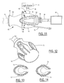
- a handle 60 includes a flange section 61 at the distal end, a neck section 62, and a bulb section 63 at the proximal end.
- a camera head cable 64 is connected to a camera head 65 that is coupled to an eyepiece unit 66 of an endoscope. The other end of camera head cable 64 is connected to a central processing unit (CPU) and monitor 67.
- a light guide cable 68 is connected to a light guide port 70 of the endoscope near eyepiece unit 66, and the other end of light guide cable 68 is coupled to a light source apparatus 71.
- Bulb section 63 includes a pair of arcs 72 and 73 comprising raised surface ridges extending substantially parallel to neck section 62. The surface ridges reduce slippage of the operators hand along handle 60.
- the profiles of the surface ridges are shown by the cross-sectional views of Figures 13 and 14 taken along lines A-A and B-B of Figure 11 , respectively.
- flange section 61 acts to reduce the force required from the operator because it more efficiently transfers the pushing force to the dissector rod and tip.
- Handle 60 provides maximum comfort and ergonomics while reducing potential for procedure-related physical complications such as carpal tunnel syndrome.
- a gas insufflation tubing member 75 is integrated with handle 60 for connecting to a gas supply (not shown). Gas is guided from the supply through gas insufflation tubing member 75, the passageway located inside the dissector, and the hole in the dissector tip to the body cavity being created in order to keep the operation site open and visible.
- the preferred gas is carbon dioxide (CO 2 ).
- a convenient length of flexible tubing is provided for gas insufflation tubing member 75. The preferable location of tubing member 75 is away from the gripping sections.
- a small clip 80 is attached to the end of tubing member 75 as shown in Figures 15 and 16 .
- clip 80 has a first fastener 81 mounted to tubing member 75 (or to an end fitting 83 that may conventionally be provided on tubing member 75).
- small clip 80 provides a second fastener that is slidably attached to a portion of the endoscope (e.g., either the light guide cable or the camera head cable).
- the second fastener is attached to light guide cable 68.
- the second fastener is attached to camera head cable 64.
- the presence of small clip 80 optimizes insufflation tube management during surgery.
- clip 80 is constructed so that the tubing member and the endoscope will be released from each other if an unusual amount of force is applied to either fastener. This protects the endoscope from accidental damage.
- Figure 17 shows clip 80 in greater detail.
- First fastener 81 has an aperture 87 into which the insufflation tube can be mounted.
- Second fastener 82 has resilient fingers 84 and 85 separated by a gap 86, wherein gap 86 is smaller than the outside diameter of the endoscope light guide cable or the camera head cable. Fingers 84 and 85 can be spread apart by an amount sufficient to insert the desired cable.
- Clip 80 can be molded rubber, plastic, or a stamped metal piece, for example.
- Figure 18 shows an alternative embodiment wherein the second fastener of clip 80 comprises a movable jaw with a first jaw member 90 and a second jaw member 91 mounted to a pivot 92.
- a spring (not shown) urges jaw members 90 and 91 into the closed position shown in Figure 18 .
- Figure 19 shows another alternative embodiment wherein a curved finger 93 is hollow to receive a curved pin 94 to form a clasp.
- Pin 94 slides within finger 93 by pushing on an extension 95 of pin 94.
- Pin 94 is retracted into the hollow in order to place the endoscope cable within the clip, and then pin 94 is extended toward curved finger 96 so that the cable is retained.
- Figure 20 shows yet another embodiment wherein the second fastener includes bendable fingers 97 and 98.
- a collar 99 is mounted to the end of finger 98 and has an open end for receiving finger 97 to form a clasp.
- Figure 21 shows another alternative wherein the second fastener is formed by sheets 101 and 102 having respective hook and loop surfaces.
- the clip is installed by pulling sheets 101 and 102 apart, passing them around a portion of the endoscope (e.g., the light guide cable or the camera head cable), and joining them back together.
- the endoscope e.g., the light guide cable or the camera head cable
Landscapes
- Health & Medical Sciences (AREA)
- Surgery (AREA)
- Life Sciences & Earth Sciences (AREA)
- Biomedical Technology (AREA)
- Nuclear Medicine, Radiotherapy & Molecular Imaging (AREA)
- Engineering & Computer Science (AREA)
- Rheumatology (AREA)
- Heart & Thoracic Surgery (AREA)
- Medical Informatics (AREA)
- Molecular Biology (AREA)
- Animal Behavior & Ethology (AREA)
- General Health & Medical Sciences (AREA)
- Public Health (AREA)
- Veterinary Medicine (AREA)
- Surgical Instruments (AREA)
Abstract
Description
- Not Applicable.
- Not Applicable.
- The present invention relates to a tissue separation dissector used for forming an elongated cavity in subcutaneous tissue, particularly along the course of a small blood vessel. More specifically, this invention relates to an endoscope-covering sheath used for endoscopic blood vessel harvesting which endoscopically harvests a subcutaneous blood vessel such as the great saphenous vein.
- Surgical methods and endoscopic dissectors for dissecting and harvesting a subcutaneous blood vessel such as a great saphenous vein are known in, for example, U.S patents 7,077,803; 6,863,674; 6,432,044; and 5,895,353, incorporated by reference in their entirety. The dissector is a straight tubular device with an internal instrument insertion passage and a handle portion provided at the proximal end of the dissector. A rigid endoscope is introduced in the instrument insertion passage of the dissector from the end of the handle portion.
- When a subcutaneous blood vessel, such as a great saphenous vein, is to be endoscopically dissected by using the dissector, a surgical method such as demonstrated by
Figure 21 is utilized. The entire length of a target blood vessel C extending from the upper portion of the inguinal region A of the thigh of alower limb 1000 to the ankle B is desired to be removed. The medical professional (i.e., the operator) performs a skin incision E2 at the knee area D, for example, immediately above the blood vessel C by means of a scalpel or the like. The operator exposes the blood vessel C in the area of the skin incision E2 by means of blunt dissection or the like. The operator parts tissue immediately above the blood vessel C by means of a dissector over a distance from a portion of skin E2 such that the blood vessel is observable to the naked eyes. Once the vessel is fully dissected from the surrounding tissue, small incisions (herein after referred to as stab wounds) are performed distal to the knee incision (e.g., at inguinal position E1 and ankle position E3) and blood vessel C is extracted through incision E2. -
Figure 22 shows a cross-sectional view taken along line 22-22 ofFigure 21 .Reference numeral 1001 denotes skin,reference numeral 1002 denotes a subcutaneous tissue, andreference numeral 1003 denotes a connective tissue overlying and surrounding blood vessel C. In a dissecting operation, the operator first uses a dissector rod having a blunt conical tip to form a cavity G between the surrounding tissue and blood vessel C. Blood vessel C is isolated from the surroundingconnective tissue 1003 anteriorly, posteriorly, laterally, and medially as much as possible using the dissector rod. Following blunt dissection fromconnective tissue 1003, blood vessel C continues to be connected to the body of the patient by side branches F of the vessel and by remaining bits of connective tissue. - In order to harvest blood vessel C, the side branches F and remaining connective tissue between the incised portions of skin E2 at knee D and inguinal region A must be removed. Thus, the operator removes the dissector rod and inserts a harvesting tool into cavity G through incised portion of skin E2. The harvester includes a keeper (i.e., loop) for slidably receiving vessel C. The operator progressively slides the tip of the harvester from incision E2 alternately toward the incised portions of skin E1 and E3 along an outer surface of blood vessel C while observing through the rigid endoscope loaded into the interior of the harvester and cutting through side branches F and remaining connective tissue using a cutter (i.e., forceps) that is integral with the keeper. In the course of the cutting operation within cavity G, the operator moves the harvester device back and forth while cutting (e.g., cauterizing) branches by manipulating a set of controls disposed at the proximal end of the harvester. An insufflation gas (e.g., CO2) is introduced into cavity G through the tip of both the dissector rod and the harvester rod to hold open cavity G and maintaining separation between vessel C and the surrounding
subcutaneous tissue 1002 andconnective tissue 1003. - During initial dissection of cavity G (referred to as the first pass), the dissector encounters high resistance so that the operator must manually apply a strong force to move forward. The resistance is due to the blood vessel C, the
connective tissue 1003 and thesubcutaneous tissue 1002 being connected tightly together. The prior art has suffered from operator fatigue and inefficient performance of the dissection/harvesting operation. - In view of the prior state of the art, it would be desirable to reduce operator strain and fatigue and to facilitate an easier and more efficient dissecting operation to overcome the tight connection of the desired blood vessel to surrounding subcutaneous and connective tissues.
- In one aspect of the invention, a blunt dissector for separating a blood vessel from surrounding tissues in a body comprises a longitudinal rod having a proximal end, a distal end, and an internal passage for conducting insufflation gas between the proximal and distal ends. An interior sleeve is mounted within the longitudinal rod for receiving an endoscope at the proximal end. A transparent tip is mounted to the distal end of the longitudinal rod. A handle is mounted to the proximal end of the longitudinal rod. The longitudinal rod has an outer surface along substantially all of the longitudinal rod between the proximal and distal ends consisting essentially of a fluoropolymer.
- We have found that when the outer surface of the dissector along the longitudinal rod is covered by or consists entirely of fluoropolymer (such as polytetrafluoroethylene), much less force is required during dissection compared to when using a conventional dissector. Moreover, a contoured handle with a flanged shape at the distal portion and a bulb shape at the proximal portion facilitate a more efficient and comfortable application of the necessary force with less likelihood of repetitive stress injury to the user.
-
-
Figure 1 is a plan view of a blunt dissector of the invention together with an endoscope and a trocar. -
Figure 2 is a side cross-sectional view of the tip of the dissector. -
Figures 3-6 are longitudinal cross sections for three separate embodiments of the invention. -
Figure 7 illustrates the surgical procedure for harvesting a vessel from the leg of a patient. -
Figure 8 illustrates the surgical procedure for harvesting a vessel from the arm of a patient. -
Figure 9 is a partial cross section showing a dissector inserted into a patient's body and guided by a trocar. -
Figure 10 is a graph showing the force required for penetrating a body with a dissector of the present invention and two prior art dissectors. -
Figure 11 is a side view showing one embodiment of a handle of the present invention and associated equipment. -
Figure 12 is a perspective view of the handle ofFigure 11 . -
Figure 13 is a longitudinal cross section along line A-A ofFigure 11 . -
Figure 14 is a longitudinal cross section along line B-B ofFigure 11 . -
Figures 15 and 16 are plan views showing an insufflation tube clipped to various parts of the endoscope. -
Figures 17-21 are plan views showing alternative shapes for the clip ofFigures 15 and 16 . -
Figures 22 and 23 illustrate a prior art vessel harvesting procedure. - A dissection system includes an
endoscope 10 to perform observation in a body, adissector apparatus 11 to dissect a blood vessel in the body, and trocar 12 to help insert theendoscope 10 anddissector apparatus 11 into the body.Endoscope 10 is a rigid endoscope and includes an elongated rod-likeinserting portion 13. The proximal end of insertingportion 13 connects to anend adapter 14 to transmit an endoscopic image. Alight guide port 15 projects fromend adapter 14.Light guide port 15 connects to a light guide cable to supply illumination light to theendoscope 10. - In a preferred embodiment,
dissector apparatus 11 includes a tubularmain body portion 16 comprising a hollow longitudinal rod within whichendoscope 10 is to be inserted.Endoscope 10 is inserted or removed fromlongitudinal rod 16 through ahandle portion 17 in one fluid forward or backward movement.Endoscope 10 is secured insidedissector 11 by asmall nub 18, found oppositelight guide port 15 onend adapter 14 ofendoscope 10 and held by a conventional mechanism found insidehandle portion 17. - The material of
longitudinal rod 16 material is selected from fluoropolymers, which are well known materials. Examples of fluoropolymers include polymers such as polytetrafluoroethylene (PTFE commonly referred to as Teflon), perfluoroalkoxy (PFA), fluorinated ethylene propylene (FEP), polyvinylidene fluoride (PVDF), ethylene-tetrafluoroethylene (ETFE), ethylene-chlorotrifluoroethylene (ECTFE), and mixtures of fluoropolymers such as MFA or THV, or mixtures of any of the foregoing. The most preferred material for constituting the outer surface oflongitudinal rod 16 is PTFE. The use of a fluoropolymer reduces the friction caused by movingrod 16 through connective tissue, thereby reducing the force required to perform a dissection. - A
dissector tip 18 to dissect a blood vessel is disposed at the distal end oflongitudinal rod 16.Trocar 12 includes abody 20 to guidedissector apparatus 11 into the incision site. Anaperture seal 21 is located on the surface of the proximal end ofbody 20.Aperture seal 21 allowsdissector 11 to be inserted inbody 20 oftrocar 12 in one fluid forward motion. The outer surface oftrocar body 20 includes a projection to engage with living tissue and a holdingportion 22 to hold thebody 20 onto the living tissue. -
Dissector 11 includes aninner sleeve 23 for receiving insertingportion 13 ofrigid endoscope 10.Sleeve 23 is disposed at the axial center oflongitudinal rod 16 which has a straight cylindrical shape.Tip member 18 has a conical shape and comprises a transparent synthetic resin material.Longitudinal rod 16 has aninternal passage 24 for conducting insufflation gas between the proximal and distal ends. The proximal end ofpassage 24 communicates with a gas supply (not shown). At its distal end,passage 24 communicates through ahole 26 inlongitudinal rod 16 with the body cavity being dissected. -
Figure 3 shows a cross section of a first embodiment ofdissector 11 taken at line 25-25 ofFigure 1 .Longitudinal rod 16 consists essentially of a fluoropolymer body shaped as a monolithic cylinder. Preferably,rod 16 may be extruded in the shape of a cylinder. Other extruded shapes are also possible, and may include ribs or bores.Sleeve 23 is also cylindrical and is preferably formed of a metal, such as stainless steel.Sleeve 23 is suspended from a mounting block (not shown) withinhandle 17 to keep it concentrically spaced fromlongitudinal rod 16. The space established betweensleeve 23 androd 16 createspassage 24. -
Figure 4 shows a cross section of a second embodiment ofdissector 11 taken at line 25-25 ofFigure 1 .Longitudinal rod 30 has a cylindrical shape to whichlongitudinal ribs 31 are added in order to directly supportinner sleeve 23.Passage 24 is thus formed betweenlongitudinal ribs 31.Figure 5 shows another alternative embodiment wherein the thickness oflongitudinal rod 32 is increased so that it supportsinner sleeve 23 all the way around its perimeter. A pair of longitudinal bores run between the proximal and distal ends ofrod 32 to provideinsufflation passage 24. -
Figure 6 shows a fourth embodiment similar to the first embodiment, except that the longitudinal rod is a composite structure having a metal cylinder 33 with anouter coating 34 comprised of a fluoropolymer. - The typical manner of using the dissector will be discussed with reference to
Figures 7-9 which show an operation of harvesting ablood vessel 40 such as a saphenous vein of a lower limb 41 (Figure 7 ) or a subcutaneous vessel of an upper limb 42 (Figure 8 ) to use the harvestedblood vessel 40 for cardiac bypass surgery. When harvestingblood vessel 40, it must be dissected fromconnective tissue 43. - To initiate the operation, an
incision 44 is made in the vicinity of aknee 45 orwrist 46 immediately aboveblood vessel 40 to be harvested.Body 20 oftrocar 12 is inserted in the incision and held by holdingportion 22 with respect to the incision.Endoscope 10 is inserted indissector apparatus 11.Light guide connector 15 ofendoscope 10 is inserted indissector 11.Small nub 18 located on the bottom portion ofendoscope 10 engages a mechanism inhandle 17 to lock them. The distal end ofendoscope 10 is caused to project from the distal end oflongitudinal rod 16 intotip 18 for providing a view throughtip 18.Endoscope 10 anddissector 11 are then inserted into the body throughtrocar 12 in one forward movement. - As indicated by arrows C1, C2, and C3 in
Figures 7 and 8 ,dissector 11 inserted in the body dissects amain duct 47 ofvessel 40 fromconnective tissue 43 as seen inFigure 9 . More specifically, by manipulatingdissector 11,tip 18 is arranged such that oneflat side 50 facesmain duct 47. Consequently,main duct 47 extends from a periphery to the center in the observed image fromendoscope 10. Withflat portion 50 being pressed againstmain duct 47,tip 18 is moved forward alongmain duct 47 and acute-angledshape 51 at the distal end oftip 18 is inserted between blood vesselconnective tissue 43 andmain duct 47 in order to progress the dissection. - As is apparent from
Figure 9 , the outer surface oflongitudinal rod 16 slides against increasing amounts ofconnective tissue 43 as the dissection progresses. The inventors have determined that friction between them significantly increases the force required to maintain the reciprocating motions involved in the dissection process. However, the use of a fluoropolymer at the outer surface ofrod 16 substantially reduces the friction, thereby reducing the force required to be applied by the person performing the dissection.Figure 10 compares test measurements from a simulation wherein a ballistic gel was used to simulate connective tissue.Line 55 represents a dissector of the present invention with a fluoropolymer outer surface for the longitudinal rod.Lines line 55 corresponding to the present invention requires less force to move through the simulated tissue. - A further feature of the invention relates to an improved handle through which an operator applies the necessary force to the dissector rod and tip. Thus, a
handle 60 includes aflange section 61 at the distal end, aneck section 62, and abulb section 63 at the proximal end. Acamera head cable 64 is connected to acamera head 65 that is coupled to aneyepiece unit 66 of an endoscope. The other end ofcamera head cable 64 is connected to a central processing unit (CPU) and monitor 67. Alight guide cable 68 is connected to alight guide port 70 of the endoscope neareyepiece unit 66, and the other end oflight guide cable 68 is coupled to alight source apparatus 71. - The arrangement having a
bulb section 63 for being gripped by the palm and last three fingers spaced from aflange section 61 with an interveningneck section 62 with a reduced diameter with respect to the bulb and flange sections, wherein the thumb and index finger grasp in or nearneck section 62, results in an improved grip that allows for comfortable application of forces and prevention of unexpected slipping of the hand during dissection.Bulb section 63 includes a pair ofarcs neck section 62. The surface ridges reduce slippage of the operators hand alonghandle 60. The profiles of the surface ridges are shown by the cross-sectional views ofFigures 13 and 14 taken along lines A-A and B-B ofFigure 11 , respectively. - The presence of
flange section 61 acts to reduce the force required from the operator because it more efficiently transfers the pushing force to the dissector rod and tip.Handle 60 provides maximum comfort and ergonomics while reducing potential for procedure-related physical complications such as carpal tunnel syndrome. - A gas
insufflation tubing member 75 is integrated withhandle 60 for connecting to a gas supply (not shown). Gas is guided from the supply through gasinsufflation tubing member 75, the passageway located inside the dissector, and the hole in the dissector tip to the body cavity being created in order to keep the operation site open and visible. The preferred gas is carbon dioxide (CO2). A convenient length of flexible tubing is provided for gasinsufflation tubing member 75. The preferable location oftubing member 75 is away from the gripping sections. - Because a certain amount of slack tubing must be provided for gas
insufflation tubing member 75, it may tangle with the user's hand and may interrupt the operation. Tangling may also cause the required gas volume to not be delivered to the distal end of the dissector correctly iftubing member 75 is bent or kinked, obstructing the gas delivery. To solve those problems, asmall clip 80 is attached to the end oftubing member 75 as shown inFigures 15 and 16 . Thus,clip 80 has afirst fastener 81 mounted to tubing member 75 (or to an end fitting 83 that may conventionally be provided on tubing member 75). The other end ofsmall clip 80 provides a second fastener that is slidably attached to a portion of the endoscope (e.g., either the light guide cable or the camera head cable). InFigure 15 , the second fastener is attached tolight guide cable 68. InFigure 16 , the second fastener is attached tocamera head cable 64. The presence ofsmall clip 80 optimizes insufflation tube management during surgery. Preferably,clip 80 is constructed so that the tubing member and the endoscope will be released from each other if an unusual amount of force is applied to either fastener. This protects the endoscope from accidental damage. -
Figure 17 showsclip 80 in greater detail.First fastener 81 has anaperture 87 into which the insufflation tube can be mounted.Second fastener 82 hasresilient fingers gap 86, whereingap 86 is smaller than the outside diameter of the endoscope light guide cable or the camera head cable.Fingers Clip 80 can be molded rubber, plastic, or a stamped metal piece, for example. -
Figure 18 shows an alternative embodiment wherein the second fastener ofclip 80 comprises a movable jaw with afirst jaw member 90 and asecond jaw member 91 mounted to a pivot 92. A spring (not shown) urgesjaw members Figure 18 . -
Figure 19 shows another alternative embodiment wherein acurved finger 93 is hollow to receive acurved pin 94 to form a clasp.Pin 94 slides withinfinger 93 by pushing on an extension 95 ofpin 94.Pin 94 is retracted into the hollow in order to place the endoscope cable within the clip, and then pin 94 is extended towardcurved finger 96 so that the cable is retained. -
Figure 20 shows yet another embodiment wherein the second fastener includesbendable fingers collar 99 is mounted to the end offinger 98 and has an open end for receivingfinger 97 to form a clasp. -
Figure 21 shows another alternative wherein the second fastener is formed bysheets sheets
Claims (23)
- A blunt dissector for separating a blood vessel from surrounding tissues in a body, comprising:a longitudinal rod having a proximal end, a distal end, and an internal passage for conducting insufflation gas between the proximal and distal ends;an interior sleeve mounted within the longitudinal rod for receiving an endoscope at the proximal end;a transparent tip mounted to the distal end of the longitudinal rod; anda handle mounted to the proximal end of the longitudinal rod;wherein the longitudinal rod has an outer surface along substantially all of the longitudinal rod between the proximal and distal ends consisting essentially of a fluoropolymer.
- The dissector of claim 1 wherein the fluoropolymer is selected from the group consisting of polytetrafluoroethylene (PTFE), perfluoroalkoxy (PFA), fluorinated ethylene propylene (FEP), polyvinylidene fluoride (PVDF), ethylene-tetrafluoroethylene (ETFE), ethylene-chlorotrifluoroethylene (ECTFE), and mixtures thereof.
- The dissector of claim 1 wherein the fluoropolymer is polytetrafluoroethylene (PTFE).
- The dissector of claim 1 wherein the outer surface comprises a coating over a support tube comprising a metal.
- The dissector of claim 1 wherein the longitudinal rod consists essentially of the fluoropolymer.
- The dissector of claim 5 wherein the longitudinal rod is formed by extruding the fluoropolymer in the shape of a cylinder.
- The dissector of claim 6 wherein the fluoropolymer is polytetrafluoroethylene (PTFE).
- The dissector of claim 1 wherein the handle comprises a contoured grip having a bulb section at a proximal end thereof, a flange section at a distal end thereof, and a reduced-diameter neck section therebetween.
- The dissector of claim 8 wherein the bulb section includes surface ridges extending substantially parallel to the neck section.
- The dissector of claim 8 wherein the handle comprises resilient material.
- The dissector of claim 1 further comprising:a flexible tubing member connected at one end to the internal passage and adapted at the other end to be connected to a gas supply; anda clip having a first fastener mounted to the flexible tubing member at a substantially fixed location and having a second fastener for slidably grasping a portion of the endoscope.
- The dissector of claim 11 wherein the portion of the endoscope is comprised of a cable.
- The dissector of claim 11 wherein the second fastener comprises a pair of resilient fingers.
- The dissector of claim 11 wherein the second fastener includes a clasp.
- The dissector of claim 11 wherein the second fastener includes hook and loop sheets.
- A blunt dissector for separating a blood vessel from surrounding tissues in a body, comprising:a longitudinal rod having a proximal end, a distal end, and an internal passage for conducting insufflation gas between the proximal and distal ends;an interior sleeve mounted within the longitudinal rod for receiving an endoscope at the proximal end;a transparent tip mounted to the distal end of the longitudinal rod; anda handle mounted to the proximal end of the longitudinal rod, wherein the handle comprises a contoured grip having a bulb section at a proximal end thereof, a flange section at a distal end thereof, and a reduced-diameter neck section therebetween;wherein the longitudinal rod having an outer cylinder consisting essentially of polytetrafluoroethylene (PTFE) to provide a PTFE outer surface along substantially all of the longitudinal rod between the proximal and distal ends for contacting the surrounding tissues.
- The dissector of claim 16 wherein the longitudinal rod is formed by extruding the PTFE in the shape of a cylinder, wherein the handle comprises resilient material, and wherein the bulb section includes surface ridges extending substantially parallel to the neck section.
- The dissector of claim 16 further comprising:a flexible tubing member connected at one end to the internal passage and adapted at the other end to be connected to a gas supply; anda clip having a first fastener mounted to the flexible tubing member at a substantially fixed location and having a second fastener for slidably grasping a portion of the endoscope.
- A blunt dissector for separating a blood vessel from surrounding tissues in a body, comprising:a longitudinal rod having a proximal end, a distal end, and an internal passage for conducting insufflation gas between the proximal and distal ends;an interior sleeve mounted within the longitudinal rod for receiving an endoscope at the proximal end;a transparent tip mounted to the distal end of the longitudinal rod; anda handle mounted to the proximal end of the longitudinal rod;a flexible tubing member connected at one end to the internal passage and adapted at the other end to be connected to an insufflation gas supply;a clip having a first fastener mounted to the flexible tubing member at a substantially fixed location and having a second fastener for slidably grasping a portion of the endoscope.
- The dissector of claim 19 wherein the portion of the endoscope is comprised of a cable.
- The dissector of claim 19 wherein the second fastener comprises a pair of resilient fingers.
- The dissector of claim 19 wherein the second fastener includes a clasp.
- The dissector of claim 19 wherein the second fastener includes hook and loop sheets.
Applications Claiming Priority (1)
| Application Number | Priority Date | Filing Date | Title |
|---|---|---|---|
| US12/136,477 US8048100B2 (en) | 2008-06-10 | 2008-06-10 | Blunt dissector for separating blood vessels from surrounding tissue |
Publications (3)
| Publication Number | Publication Date |
|---|---|
| EP2133027A2 true EP2133027A2 (en) | 2009-12-16 |
| EP2133027A3 EP2133027A3 (en) | 2011-12-07 |
| EP2133027B1 EP2133027B1 (en) | 2016-08-31 |
Family
ID=41100635
Family Applications (1)
| Application Number | Title | Priority Date | Filing Date |
|---|---|---|---|
| EP09161777.9A Active EP2133027B1 (en) | 2008-06-10 | 2009-06-03 | Blunt Dissector for Separating Blood Vessels from Surrounding Tissue |
Country Status (3)
| Country | Link |
|---|---|
| US (1) | US8048100B2 (en) |
| EP (1) | EP2133027B1 (en) |
| JP (1) | JP2009297505A (en) |
Cited By (3)
| Publication number | Priority date | Publication date | Assignee | Title |
|---|---|---|---|---|
| WO2012003107A1 (en) * | 2010-07-01 | 2012-01-05 | Lexion Medical, Llc | A surgical method for performing a coronary blood vessel bypass |
| WO2013000536A1 (en) * | 2011-06-30 | 2013-01-03 | Siegfried Riek | Trocar system |
| US9687270B2 (en) | 2012-03-13 | 2017-06-27 | Thomas Gaiselmann | Instrument system for minimally invasive surgery in single port technology |
Families Citing this family (11)
| Publication number | Priority date | Publication date | Assignee | Title |
|---|---|---|---|---|
| US8267951B2 (en) * | 2008-06-12 | 2012-09-18 | Ncontact Surgical, Inc. | Dissecting cannula and methods of use thereof |
| US9119900B2 (en) | 2011-12-23 | 2015-09-01 | Saphena Medical, Inc. | Unitary endoscopic vessel harvesting devices |
| US8920456B2 (en) | 2012-04-18 | 2014-12-30 | Terumo Cardiovascular Systems Corp. | Insufflation damper for endoscopic vessel dissector/harvester |
| CN104619275B (en) | 2012-04-28 | 2018-05-04 | 物理科学公司 | Method and apparatus for soft tissue anatomical |
| US9592069B2 (en) | 2012-04-28 | 2017-03-14 | Physcient, Inc. | Methods and devices for soft tissue dissection |
| AU2014233486B2 (en) * | 2013-03-15 | 2018-11-15 | DePuy Synthes Products, Inc. | Viewing trocar with integrated prism for use with angled endoscope |
| WO2015161249A1 (en) | 2014-04-18 | 2015-10-22 | Physcient, Inc. | Methods and devices for soft tissue dissection |
| US10383651B2 (en) | 2014-04-22 | 2019-08-20 | Physcient, Inc. | Instruments, devices, and related methods for soft tissue dissection |
| US10582914B2 (en) | 2016-01-15 | 2020-03-10 | Covidien Lp | Navigable endobronchial tool to access tissue outside a bronchus |
| US20230053189A1 (en) | 2021-08-11 | 2023-02-16 | Terumo Cardiovascular Systems Corporation | Augmented-reality endoscopic vessel harvesting |
| US20230051869A1 (en) | 2021-08-11 | 2023-02-16 | Terumo Cardiovascular Systems Corporation | Endoscopic vessel harvesting with thermal management and augmented reality display |
Citations (4)
| Publication number | Priority date | Publication date | Assignee | Title |
|---|---|---|---|---|
| US5895353A (en) | 1998-06-22 | 1999-04-20 | Origin Medsystems, Inc. | Vessel isolating retractor cannula and method |
| US6432044B1 (en) | 1999-01-08 | 2002-08-13 | Origin Medsystems, Inc. | Combined vessel dissection and transection device and method |
| US6863674B2 (en) | 2001-12-28 | 2005-03-08 | Olympus Corporation | Operating trocar |
| US7077803B2 (en) | 2001-12-28 | 2006-07-18 | Olympus Corporation | Living tissue harvesting apparatus |
Family Cites Families (37)
| Publication number | Priority date | Publication date | Assignee | Title |
|---|---|---|---|---|
| JPS59182302U (en) * | 1983-05-18 | 1984-12-05 | 旭光学工業株式会社 | Endoscope with tying tube |
| US4707906A (en) * | 1986-03-25 | 1987-11-24 | Posey John T | Method of attaching tube to a tube holder |
| US5334159A (en) * | 1992-03-30 | 1994-08-02 | Symbiosis Corporation | Thoracentesis needle assembly utilizing check valve |
| US5980549A (en) | 1995-07-13 | 1999-11-09 | Origin Medsystems, Inc. | Tissue separation cannula with dissection probe and method |
| US5702417A (en) | 1995-05-22 | 1997-12-30 | General Surgical Innovations, Inc. | Balloon loaded dissecting instruments |
| US6596010B1 (en) | 1995-05-22 | 2003-07-22 | General Surgical Innovations, Inc. | Balloon dissecting instruments |
| US7037317B2 (en) | 1995-05-22 | 2006-05-02 | United States Surgical Corporation | Balloon dissecting instruments |
| US5944734A (en) | 1995-05-22 | 1999-08-31 | General Surgical Innovations, Inc. | Balloon dissecting instruments |
| US5993472A (en) | 1995-05-22 | 1999-11-30 | General Surgical Innovations, Inc. | Balloon dissecting instruments |
| US5893866A (en) | 1995-05-22 | 1999-04-13 | General Surgical Innovations, Inc. | Balloon dissecting instruments |
| US6004340A (en) | 1995-05-22 | 1999-12-21 | General Surgical Innovations, Inc. | Balloon dissecting instruments |
| US5599001A (en) * | 1995-05-30 | 1997-02-04 | Dwyer; Joseph G. | Stuffed animal conduit retainer |
| US5979452A (en) | 1995-06-07 | 1999-11-09 | General Surgical Innovations, Inc. | Endoscopic linton procedure using balloon dissectors and retractors |
| US5759150A (en) * | 1995-07-07 | 1998-06-02 | Olympus Optical Co., Ltd. | System for evulsing subcutaneous tissue |
| US5968065A (en) | 1995-07-13 | 1999-10-19 | Origin Medsystems, Inc. | Tissue separation cannula |
| CA2244164A1 (en) * | 1996-01-24 | 1997-07-31 | Albert K. Chin | Tissue separation cannula with dissection probe and method |
| WO1999039632A1 (en) * | 1998-02-06 | 1999-08-12 | Evans David K | Device for visualizing, dissecting and harvesting vessels |
| US6296640B1 (en) * | 1998-02-06 | 2001-10-02 | Ethicon Endo-Surgery, Inc. | RF bipolar end effector for use in electrosurgical instruments |
| US6261241B1 (en) * | 1998-03-03 | 2001-07-17 | Senorx, Inc. | Electrosurgical biopsy device and method |
| US6165140A (en) | 1998-12-28 | 2000-12-26 | Micrus Corporation | Composite guidewire |
| US20040102804A1 (en) * | 1999-08-10 | 2004-05-27 | Chin Albert K. | Apparatus and methods for endoscopic surgical procedures |
| JP2001061773A (en) * | 1999-08-31 | 2001-03-13 | Olympus Optical Co Ltd | Valve device for endoscope and water feed tube with valve as well as endoscope system |
| US6471638B1 (en) | 2000-04-28 | 2002-10-29 | Origin Medsystems, Inc. | Surgical apparatus |
| US6951568B1 (en) | 2000-07-10 | 2005-10-04 | Origin Medsystems, Inc. | Low-profile multi-function vessel harvester and method |
| WO2002032335A1 (en) * | 2000-07-25 | 2002-04-25 | Rita Medical Systems Inc. | Apparatus for detecting and treating tumors using localized impedance measurement |
| US6958069B2 (en) | 2001-01-17 | 2005-10-25 | Mark LoGuidice | Instruments and methods for use in laparoscopic surgery |
| US6743228B2 (en) * | 2001-09-12 | 2004-06-01 | Manoa Medical, Inc. | Devices and methods for tissue severing and removal |
| ATE526883T1 (en) | 2001-12-27 | 2011-10-15 | Olympus Corp | COVER WITH DEVICES FOR ENDOSCOPIC HARVESTING OF BLOOD VESSELS |
| JP3671002B2 (en) | 2001-12-28 | 2005-07-13 | オリンパス株式会社 | Endoscope sheath |
| EP1323392B1 (en) | 2001-12-28 | 2011-02-09 | Olympus Corporation | Treatment device for cutting living tissue |
| US20040092990A1 (en) * | 2002-07-11 | 2004-05-13 | Opie John C. | Endovascular guide for use with a percutaneous device for harvesting tubular body members |
| US20050149094A1 (en) | 2003-10-31 | 2005-07-07 | Olympus Corporation | Trocar |
| US20060173474A1 (en) | 2003-10-31 | 2006-08-03 | Parris Wellman | Surgical device having a track to guide an actuator |
| US7331971B2 (en) * | 2003-10-31 | 2008-02-19 | Olympus Corporation | Living-body tissue removing apparatus |
| WO2005086648A2 (en) * | 2004-02-27 | 2005-09-22 | Custom Spine, Inc. | Screwdriver |
| JP2006087609A (en) * | 2004-09-22 | 2006-04-06 | Olympus Corp | Biological tissue acquisition apparatus |
| US20070282272A1 (en) * | 2006-05-30 | 2007-12-06 | Bannon Chad D | Device for guiding medical tubing |
-
2008
- 2008-06-10 US US12/136,477 patent/US8048100B2/en not_active Expired - Fee Related
-
2009
- 2009-05-21 JP JP2009122759A patent/JP2009297505A/en active Pending
- 2009-06-03 EP EP09161777.9A patent/EP2133027B1/en active Active
Patent Citations (4)
| Publication number | Priority date | Publication date | Assignee | Title |
|---|---|---|---|---|
| US5895353A (en) | 1998-06-22 | 1999-04-20 | Origin Medsystems, Inc. | Vessel isolating retractor cannula and method |
| US6432044B1 (en) | 1999-01-08 | 2002-08-13 | Origin Medsystems, Inc. | Combined vessel dissection and transection device and method |
| US6863674B2 (en) | 2001-12-28 | 2005-03-08 | Olympus Corporation | Operating trocar |
| US7077803B2 (en) | 2001-12-28 | 2006-07-18 | Olympus Corporation | Living tissue harvesting apparatus |
Cited By (3)
| Publication number | Priority date | Publication date | Assignee | Title |
|---|---|---|---|---|
| WO2012003107A1 (en) * | 2010-07-01 | 2012-01-05 | Lexion Medical, Llc | A surgical method for performing a coronary blood vessel bypass |
| WO2013000536A1 (en) * | 2011-06-30 | 2013-01-03 | Siegfried Riek | Trocar system |
| US9687270B2 (en) | 2012-03-13 | 2017-06-27 | Thomas Gaiselmann | Instrument system for minimally invasive surgery in single port technology |
Also Published As
| Publication number | Publication date |
|---|---|
| EP2133027B1 (en) | 2016-08-31 |
| US20090306699A1 (en) | 2009-12-10 |
| JP2009297505A (en) | 2009-12-24 |
| EP2133027A3 (en) | 2011-12-07 |
| US8048100B2 (en) | 2011-11-01 |
Similar Documents
| Publication | Publication Date | Title |
|---|---|---|
| US8048100B2 (en) | Blunt dissector for separating blood vessels from surrounding tissue | |
| US20200046393A1 (en) | Apparatus and methods for performing minimally-invasive surgical procedures | |
| US5433722A (en) | Ligature carrier for endoscopic use | |
| US6817978B2 (en) | Illuminated retractor for use in connection with harvesting a blood vessel from the arm | |
| US5499997A (en) | Endoscopic tenaculum surgical instrument | |
| US8926642B2 (en) | Method for extracting tubular structures | |
| US8246575B2 (en) | Flexible hollow spine with locking feature and manipulation structure | |
| US5624381A (en) | Surgical instrument and method for retraction of an anatomic structure defining an interior lumen | |
| JP4690426B2 (en) | Tissue peeling tip and peeling device provided with the same | |
| JP4982699B2 (en) | Biopsy forceps | |
| US20100292533A1 (en) | Endoscopic Cutter with Reconfigurable Guides | |
| EP0577423A2 (en) | Endoscopic instrument system | |
| AU2003205103A1 (en) | Illuminated retractor for use in connection with harvesting a blood vessel from the arm | |
| IL135371A (en) | Resectoscope | |
| EP2228014A1 (en) | Rib retractor | |
| US11540839B2 (en) | Clip unit, mucous membrane lifting system, and mucous membrane lifting method | |
| US9119900B2 (en) | Unitary endoscopic vessel harvesting devices | |
| JP3839320B2 (en) | Biological tissue cutting treatment tool | |
| US20110196407A1 (en) | Multiple function surgical instrument | |
| Whalan | A guide to assisting at surgical operations 2: handling surgical instruments |
Legal Events
| Date | Code | Title | Description |
|---|---|---|---|
| PUAI | Public reference made under article 153(3) epc to a published international application that has entered the european phase |
Free format text: ORIGINAL CODE: 0009012 |
|
| AK | Designated contracting states |
Kind code of ref document: A2 Designated state(s): AT BE BG CH CY CZ DE DK EE ES FI FR GB GR HR HU IE IS IT LI LT LU LV MC MK MT NL NO PL PT RO SE SI SK TR |
|
| PUAL | Search report despatched |
Free format text: ORIGINAL CODE: 0009013 |
|
| AK | Designated contracting states |
Kind code of ref document: A3 Designated state(s): AT BE BG CH CY CZ DE DK EE ES FI FR GB GR HR HU IE IS IT LI LT LU LV MC MK MT NL NO PL PT RO SE SI SK TR |
|
| RIC1 | Information provided on ipc code assigned before grant |
Ipc: A61B 17/00 20060101AFI20111103BHEP |
|
| 17P | Request for examination filed |
Effective date: 20120326 |
|
| RAP1 | Party data changed (applicant data changed or rights of an application transferred) |
Owner name: TERUMO CARDIOVASCULAR SYSTEMS CORPORATION Owner name: OLYMPUS CORPORATION |
|
| GRAP | Despatch of communication of intention to grant a patent |
Free format text: ORIGINAL CODE: EPIDOSNIGR1 |
|
| INTG | Intention to grant announced |
Effective date: 20160331 |
|
| RIN1 | Information on inventor provided before grant (corrected) |
Inventor name: KADYKOWSKI, RANDAL J. Inventor name: KANO, AKIHITO Inventor name: YAMATANI, KEN Inventor name: KASAHARA, HIDEYUKI Inventor name: MAEDA, SEIJI Inventor name: CHARRON-KELLER, LYNE M. Inventor name: KOMAGATA, SUSUMU |
|
| GRAS | Grant fee paid |
Free format text: ORIGINAL CODE: EPIDOSNIGR3 |
|
| GRAA | (expected) grant |
Free format text: ORIGINAL CODE: 0009210 |
|
| AK | Designated contracting states |
Kind code of ref document: B1 Designated state(s): AT BE BG CH CY CZ DE DK EE ES FI FR GB GR HR HU IE IS IT LI LT LU LV MC MK MT NL NO PL PT RO SE SI SK TR |
|
| REG | Reference to a national code |
Ref country code: CH Ref legal event code: EP Ref country code: GB Ref legal event code: FG4D |
|
| REG | Reference to a national code |
Ref country code: IE Ref legal event code: FG4D |
|
| REG | Reference to a national code |
Ref country code: DE Ref legal event code: R096 Ref document number: 602009040733 Country of ref document: DE |
|
| REG | Reference to a national code |
Ref country code: AT Ref legal event code: REF Ref document number: 824241 Country of ref document: AT Kind code of ref document: T Effective date: 20161015 |
|
| REG | Reference to a national code |
Ref country code: LT Ref legal event code: MG4D |
|
| REG | Reference to a national code |
Ref country code: NL Ref legal event code: MP Effective date: 20160831 |
|
| REG | Reference to a national code |
Ref country code: AT Ref legal event code: MK05 Ref document number: 824241 Country of ref document: AT Kind code of ref document: T Effective date: 20160831 |
|
| PG25 | Lapsed in a contracting state [announced via postgrant information from national office to epo] |
Ref country code: LT Free format text: LAPSE BECAUSE OF FAILURE TO SUBMIT A TRANSLATION OF THE DESCRIPTION OR TO PAY THE FEE WITHIN THE PRESCRIBED TIME-LIMIT Effective date: 20160831 Ref country code: HR Free format text: LAPSE BECAUSE OF FAILURE TO SUBMIT A TRANSLATION OF THE DESCRIPTION OR TO PAY THE FEE WITHIN THE PRESCRIBED TIME-LIMIT Effective date: 20160831 Ref country code: NO Free format text: LAPSE BECAUSE OF FAILURE TO SUBMIT A TRANSLATION OF THE DESCRIPTION OR TO PAY THE FEE WITHIN THE PRESCRIBED TIME-LIMIT Effective date: 20161130 Ref country code: FI Free format text: LAPSE BECAUSE OF FAILURE TO SUBMIT A TRANSLATION OF THE DESCRIPTION OR TO PAY THE FEE WITHIN THE PRESCRIBED TIME-LIMIT Effective date: 20160831 |
|
| PG25 | Lapsed in a contracting state [announced via postgrant information from national office to epo] |
Ref country code: AT Free format text: LAPSE BECAUSE OF FAILURE TO SUBMIT A TRANSLATION OF THE DESCRIPTION OR TO PAY THE FEE WITHIN THE PRESCRIBED TIME-LIMIT Effective date: 20160831 Ref country code: GR Free format text: LAPSE BECAUSE OF FAILURE TO SUBMIT A TRANSLATION OF THE DESCRIPTION OR TO PAY THE FEE WITHIN THE PRESCRIBED TIME-LIMIT Effective date: 20161201 Ref country code: LV Free format text: LAPSE BECAUSE OF FAILURE TO SUBMIT A TRANSLATION OF THE DESCRIPTION OR TO PAY THE FEE WITHIN THE PRESCRIBED TIME-LIMIT Effective date: 20160831 Ref country code: ES Free format text: LAPSE BECAUSE OF FAILURE TO SUBMIT A TRANSLATION OF THE DESCRIPTION OR TO PAY THE FEE WITHIN THE PRESCRIBED TIME-LIMIT Effective date: 20160831 Ref country code: SE Free format text: LAPSE BECAUSE OF FAILURE TO SUBMIT A TRANSLATION OF THE DESCRIPTION OR TO PAY THE FEE WITHIN THE PRESCRIBED TIME-LIMIT Effective date: 20160831 Ref country code: NL Free format text: LAPSE BECAUSE OF FAILURE TO SUBMIT A TRANSLATION OF THE DESCRIPTION OR TO PAY THE FEE WITHIN THE PRESCRIBED TIME-LIMIT Effective date: 20160831 |
|
| PG25 | Lapsed in a contracting state [announced via postgrant information from national office to epo] |
Ref country code: RO Free format text: LAPSE BECAUSE OF FAILURE TO SUBMIT A TRANSLATION OF THE DESCRIPTION OR TO PAY THE FEE WITHIN THE PRESCRIBED TIME-LIMIT Effective date: 20160831 Ref country code: EE Free format text: LAPSE BECAUSE OF FAILURE TO SUBMIT A TRANSLATION OF THE DESCRIPTION OR TO PAY THE FEE WITHIN THE PRESCRIBED TIME-LIMIT Effective date: 20160831 |
|
| PG25 | Lapsed in a contracting state [announced via postgrant information from national office to epo] |
Ref country code: CZ Free format text: LAPSE BECAUSE OF FAILURE TO SUBMIT A TRANSLATION OF THE DESCRIPTION OR TO PAY THE FEE WITHIN THE PRESCRIBED TIME-LIMIT Effective date: 20160831 Ref country code: BG Free format text: LAPSE BECAUSE OF FAILURE TO SUBMIT A TRANSLATION OF THE DESCRIPTION OR TO PAY THE FEE WITHIN THE PRESCRIBED TIME-LIMIT Effective date: 20161130 Ref country code: PT Free format text: LAPSE BECAUSE OF FAILURE TO SUBMIT A TRANSLATION OF THE DESCRIPTION OR TO PAY THE FEE WITHIN THE PRESCRIBED TIME-LIMIT Effective date: 20170102 Ref country code: PL Free format text: LAPSE BECAUSE OF FAILURE TO SUBMIT A TRANSLATION OF THE DESCRIPTION OR TO PAY THE FEE WITHIN THE PRESCRIBED TIME-LIMIT Effective date: 20160831 Ref country code: DK Free format text: LAPSE BECAUSE OF FAILURE TO SUBMIT A TRANSLATION OF THE DESCRIPTION OR TO PAY THE FEE WITHIN THE PRESCRIBED TIME-LIMIT Effective date: 20160831 Ref country code: BE Free format text: LAPSE BECAUSE OF FAILURE TO SUBMIT A TRANSLATION OF THE DESCRIPTION OR TO PAY THE FEE WITHIN THE PRESCRIBED TIME-LIMIT Effective date: 20160831 Ref country code: SK Free format text: LAPSE BECAUSE OF FAILURE TO SUBMIT A TRANSLATION OF THE DESCRIPTION OR TO PAY THE FEE WITHIN THE PRESCRIBED TIME-LIMIT Effective date: 20160831 |
|
| REG | Reference to a national code |
Ref country code: DE Ref legal event code: R097 Ref document number: 602009040733 Country of ref document: DE |
|
| REG | Reference to a national code |
Ref country code: FR Ref legal event code: PLFP Year of fee payment: 9 |
|
| PG25 | Lapsed in a contracting state [announced via postgrant information from national office to epo] |
Ref country code: IT Free format text: LAPSE BECAUSE OF FAILURE TO SUBMIT A TRANSLATION OF THE DESCRIPTION OR TO PAY THE FEE WITHIN THE PRESCRIBED TIME-LIMIT Effective date: 20160831 |
|
| PLBE | No opposition filed within time limit |
Free format text: ORIGINAL CODE: 0009261 |
|
| STAA | Information on the status of an ep patent application or granted ep patent |
Free format text: STATUS: NO OPPOSITION FILED WITHIN TIME LIMIT |
|
| 26N | No opposition filed |
Effective date: 20170601 |
|
| PG25 | Lapsed in a contracting state [announced via postgrant information from national office to epo] |
Ref country code: SI Free format text: LAPSE BECAUSE OF FAILURE TO SUBMIT A TRANSLATION OF THE DESCRIPTION OR TO PAY THE FEE WITHIN THE PRESCRIBED TIME-LIMIT Effective date: 20160831 |
|
| PG25 | Lapsed in a contracting state [announced via postgrant information from national office to epo] |
Ref country code: MC Free format text: LAPSE BECAUSE OF FAILURE TO SUBMIT A TRANSLATION OF THE DESCRIPTION OR TO PAY THE FEE WITHIN THE PRESCRIBED TIME-LIMIT Effective date: 20160831 |
|
| REG | Reference to a national code |
Ref country code: CH Ref legal event code: PL |
|
| REG | Reference to a national code |
Ref country code: IE Ref legal event code: MM4A |
|
| PG25 | Lapsed in a contracting state [announced via postgrant information from national office to epo] |
Ref country code: IE Free format text: LAPSE BECAUSE OF NON-PAYMENT OF DUE FEES Effective date: 20170603 Ref country code: LI Free format text: LAPSE BECAUSE OF NON-PAYMENT OF DUE FEES Effective date: 20170630 Ref country code: LU Free format text: LAPSE BECAUSE OF NON-PAYMENT OF DUE FEES Effective date: 20170603 Ref country code: CH Free format text: LAPSE BECAUSE OF NON-PAYMENT OF DUE FEES Effective date: 20170630 |
|
| REG | Reference to a national code |
Ref country code: FR Ref legal event code: PLFP Year of fee payment: 10 |
|
| PG25 | Lapsed in a contracting state [announced via postgrant information from national office to epo] |
Ref country code: MT Free format text: LAPSE BECAUSE OF NON-PAYMENT OF DUE FEES Effective date: 20170603 |
|
| PG25 | Lapsed in a contracting state [announced via postgrant information from national office to epo] |
Ref country code: HU Free format text: LAPSE BECAUSE OF FAILURE TO SUBMIT A TRANSLATION OF THE DESCRIPTION OR TO PAY THE FEE WITHIN THE PRESCRIBED TIME-LIMIT; INVALID AB INITIO Effective date: 20090603 |
|
| PG25 | Lapsed in a contracting state [announced via postgrant information from national office to epo] |
Ref country code: CY Free format text: LAPSE BECAUSE OF NON-PAYMENT OF DUE FEES Effective date: 20160831 |
|
| PG25 | Lapsed in a contracting state [announced via postgrant information from national office to epo] |
Ref country code: MK Free format text: LAPSE BECAUSE OF FAILURE TO SUBMIT A TRANSLATION OF THE DESCRIPTION OR TO PAY THE FEE WITHIN THE PRESCRIBED TIME-LIMIT Effective date: 20160831 |
|
| PG25 | Lapsed in a contracting state [announced via postgrant information from national office to epo] |
Ref country code: TR Free format text: LAPSE BECAUSE OF FAILURE TO SUBMIT A TRANSLATION OF THE DESCRIPTION OR TO PAY THE FEE WITHIN THE PRESCRIBED TIME-LIMIT Effective date: 20160831 |
|
| PG25 | Lapsed in a contracting state [announced via postgrant information from national office to epo] |
Ref country code: IS Free format text: LAPSE BECAUSE OF FAILURE TO SUBMIT A TRANSLATION OF THE DESCRIPTION OR TO PAY THE FEE WITHIN THE PRESCRIBED TIME-LIMIT Effective date: 20161231 |
|
| REG | Reference to a national code |
Ref country code: DE Ref legal event code: R082 Ref document number: 602009040733 Country of ref document: DE Representative=s name: FISH & RICHARDSON P.C., DE Ref country code: DE Ref legal event code: R082 Ref document number: 602009040733 Country of ref document: DE Representative=s name: HL KEMPNER PATENTANWAELTE, SOLICITORS (ENGLAND, DE Ref country code: DE Ref legal event code: R082 Ref document number: 602009040733 Country of ref document: DE Representative=s name: HL KEMPNER PATENTANWALT, RECHTSANWALT, SOLICIT, DE |
|
| PGFP | Annual fee paid to national office [announced via postgrant information from national office to epo] |
Ref country code: FR Payment date: 20230421 Year of fee payment: 15 Ref country code: DE Payment date: 20230418 Year of fee payment: 15 |
|
| P01 | Opt-out of the competence of the unified patent court (upc) registered |
Effective date: 20230714 |
|
| PGFP | Annual fee paid to national office [announced via postgrant information from national office to epo] |
Ref country code: GB Payment date: 20230420 Year of fee payment: 15 |
|
| REG | Reference to a national code |
Ref country code: DE Ref legal event code: R082 Ref document number: 602009040733 Country of ref document: DE Representative=s name: FISH & RICHARDSON P.C., DE |