EP2133056A2 - Transport apparatus - Google Patents
Transport apparatus Download PDFInfo
- Publication number
- EP2133056A2 EP2133056A2 EP09251543A EP09251543A EP2133056A2 EP 2133056 A2 EP2133056 A2 EP 2133056A2 EP 09251543 A EP09251543 A EP 09251543A EP 09251543 A EP09251543 A EP 09251543A EP 2133056 A2 EP2133056 A2 EP 2133056A2
- Authority
- EP
- European Patent Office
- Prior art keywords
- frame
- caster
- assembly
- transport
- gear
- Prior art date
- Legal status (The legal status is an assumption and is not a legal conclusion. Google has not performed a legal analysis and makes no representation as to the accuracy of the status listed.)
- Withdrawn
Links
Images


Classifications
-
- B—PERFORMING OPERATIONS; TRANSPORTING
- B62—LAND VEHICLES FOR TRAVELLING OTHERWISE THAN ON RAILS
- B62B—HAND-PROPELLED VEHICLES, e.g. HAND CARTS OR PERAMBULATORS; SLEDGES
- B62B5/00—Accessories or details specially adapted for hand carts
- B62B5/04—Braking mechanisms; Locking devices against movement
-
- A—HUMAN NECESSITIES
- A61—MEDICAL OR VETERINARY SCIENCE; HYGIENE
- A61G—TRANSPORT, PERSONAL CONVEYANCES, OR ACCOMMODATION SPECIALLY ADAPTED FOR PATIENTS OR DISABLED PERSONS; OPERATING TABLES OR CHAIRS; CHAIRS FOR DENTISTRY; FUNERAL DEVICES
- A61G1/00—Stretchers
- A61G1/02—Stretchers with wheels
- A61G1/0206—Stretchers with wheels characterised by the number of supporting wheels if stretcher is extended
- A61G1/0212—2 pairs having wheels within a pair on the same position in longitudinal direction, e.g. on the same axis
-
- A—HUMAN NECESSITIES
- A61—MEDICAL OR VETERINARY SCIENCE; HYGIENE
- A61G—TRANSPORT, PERSONAL CONVEYANCES, OR ACCOMMODATION SPECIALLY ADAPTED FOR PATIENTS OR DISABLED PERSONS; OPERATING TABLES OR CHAIRS; CHAIRS FOR DENTISTRY; FUNERAL DEVICES
- A61G1/00—Stretchers
- A61G1/02—Stretchers with wheels
- A61G1/0237—Stretchers with wheels having at least one swivelling wheel, e.g. castors
-
- A—HUMAN NECESSITIES
- A61—MEDICAL OR VETERINARY SCIENCE; HYGIENE
- A61G—TRANSPORT, PERSONAL CONVEYANCES, OR ACCOMMODATION SPECIALLY ADAPTED FOR PATIENTS OR DISABLED PERSONS; OPERATING TABLES OR CHAIRS; CHAIRS FOR DENTISTRY; FUNERAL DEVICES
- A61G1/00—Stretchers
- A61G1/02—Stretchers with wheels
- A61G1/0287—Stretchers with wheels having brakes, e.g. slowing down and/or holding
-
- A—HUMAN NECESSITIES
- A61—MEDICAL OR VETERINARY SCIENCE; HYGIENE
- A61G—TRANSPORT, PERSONAL CONVEYANCES, OR ACCOMMODATION SPECIALLY ADAPTED FOR PATIENTS OR DISABLED PERSONS; OPERATING TABLES OR CHAIRS; CHAIRS FOR DENTISTRY; FUNERAL DEVICES
- A61G1/00—Stretchers
- A61G1/02—Stretchers with wheels
- A61G1/0293—Stretchers with wheels stretcher supports with wheels, e.g. used for stretchers without wheels
-
- A—HUMAN NECESSITIES
- A61—MEDICAL OR VETERINARY SCIENCE; HYGIENE
- A61G—TRANSPORT, PERSONAL CONVEYANCES, OR ACCOMMODATION SPECIALLY ADAPTED FOR PATIENTS OR DISABLED PERSONS; OPERATING TABLES OR CHAIRS; CHAIRS FOR DENTISTRY; FUNERAL DEVICES
- A61G7/00—Beds specially adapted for nursing; Devices for lifting patients or disabled persons
- A61G7/05—Parts, details or accessories of beds
- A61G7/0528—Steering or braking devices for castor wheels
-
- B—PERFORMING OPERATIONS; TRANSPORTING
- B60—VEHICLES IN GENERAL
- B60T—VEHICLE BRAKE CONTROL SYSTEMS OR PARTS THEREOF; BRAKE CONTROL SYSTEMS OR PARTS THEREOF, IN GENERAL; ARRANGEMENT OF BRAKING ELEMENTS ON VEHICLES IN GENERAL; PORTABLE DEVICES FOR PREVENTING UNWANTED MOVEMENT OF VEHICLES; VEHICLE MODIFICATIONS TO FACILITATE COOLING OF BRAKES
- B60T1/00—Arrangements of braking elements, i.e. of those parts where braking effect occurs specially for vehicles
- B60T1/02—Arrangements of braking elements, i.e. of those parts where braking effect occurs specially for vehicles acting by retarding wheels
- B60T1/04—Arrangements of braking elements, i.e. of those parts where braking effect occurs specially for vehicles acting by retarding wheels acting directly on tread
-
- A—HUMAN NECESSITIES
- A61—MEDICAL OR VETERINARY SCIENCE; HYGIENE
- A61G—TRANSPORT, PERSONAL CONVEYANCES, OR ACCOMMODATION SPECIALLY ADAPTED FOR PATIENTS OR DISABLED PERSONS; OPERATING TABLES OR CHAIRS; CHAIRS FOR DENTISTRY; FUNERAL DEVICES
- A61G7/00—Beds specially adapted for nursing; Devices for lifting patients or disabled persons
- A61G7/002—Beds specially adapted for nursing; Devices for lifting patients or disabled persons having adjustable mattress frame
- A61G7/012—Beds specially adapted for nursing; Devices for lifting patients or disabled persons having adjustable mattress frame raising or lowering of the whole mattress frame
-
- B—PERFORMING OPERATIONS; TRANSPORTING
- B62—LAND VEHICLES FOR TRAVELLING OTHERWISE THAN ON RAILS
- B62B—HAND-PROPELLED VEHICLES, e.g. HAND CARTS OR PERAMBULATORS; SLEDGES
- B62B5/00—Accessories or details specially adapted for hand carts
- B62B5/04—Braking mechanisms; Locking devices against movement
- B62B5/0485—Braking mechanisms; Locking devices against movement by braking on the running surface, e.g. the tyre
Landscapes
- Health & Medical Sciences (AREA)
- General Health & Medical Sciences (AREA)
- Veterinary Medicine (AREA)
- Public Health (AREA)
- Life Sciences & Earth Sciences (AREA)
- Animal Behavior & Ethology (AREA)
- Engineering & Computer Science (AREA)
- Transportation (AREA)
- Mechanical Engineering (AREA)
- Nursing (AREA)
- Chemical & Material Sciences (AREA)
- Combustion & Propulsion (AREA)
- Invalid Beds And Related Equipment (AREA)
- Accommodation For Nursing Or Treatment Tables (AREA)
- Intermediate Stations On Conveyors (AREA)
Abstract
Description
- This disclosure relates generally to transport apparatuses. More particularly, but not exclusively, one embodiment relates to a patient support apparatus having caster assemblies that are movable with respect to a frame such that the frame frictionally engages the caster assemblies to affect a brake application.
- Brake systems for patient support apparatuses can provide a braking force to stop or slow patient support apparatuses that are in motion, and/or can provide a force to prevent patient support apparatuses from being moved. However, some brake systems can substantially affect the height profile of the patient support apparatuses and, consequently, the ease with which patients can exit the patient support apparatuses. Also, some brake systems can cause significant wear and damage to the caster wheel portions that interface with the floor. Moreover, some such brake systems can require a substantial amount of force initially to move the patient support apparatuses from the stationary position (i.e., activation force), and/or can cause inadequate pressure to be exerted between the caster wheels and floor, which can affect the patient support apparatuses' mobility and ease of use. While various transport apparatuses and brake systems have been developed, there is still room for improvement. Thus, a need persists for further contributions in this area of technology.
- One illustrative embodiment can include a patient support apparatus supported on a transport apparatus configured to move with respect to a frame such that the frame selectively engages a rotational element to resist rotation of the rotational element, which can result in affecting a brake application. In other embodiments, a synchronization system can be configured to synchronize the movement of one or more transport apparatuses with respect to the frame, which can result in affecting a brake application.
- In another embodiment a patient support apparatus comprises a frame, an actuator assembly, coupled to the frame, and a caster assembly supporting the frame, a portion of the actuator assembly configured to move at least one of the caster assembly and the frame relative one another to at least one of engage and disengage a portion of the caster assembly and a portion of the frame to selectively resist rotation of the portion of the caster assembly with respect to the frame.
- The caster assembly may include a caster shaft and a wheel coupled to the caster shaft. The wheel may be substantially parallel to the caster shaft.
Alternatively, the wheel may be at an angle with respect to the caster shaft and the wheel includes an engagement surface, wherein a first portion of the engagement surface is configured to contact a floor and a second portion of the engagement surface is configured to frictionally contact the portion of the frame, the first portion and the second portion being different portions of the engagement surface. In one configuration, the first portion is along an edge of the engagement surface and the second portion is along another edge of the engagement surface and the first portion does not contact the frame and the second portion does not contact the floor. - In one configuration, the actuator assembly includes a cam shaft, a portion of the cam shaft includes at least one of an area recessed from the surface of the cam shaft and an area raised from the surface of the cam shaft, the portion of the cam shaft being adapted to engage a portion of the caster assembly to move at least one of the frame and the caster assembly from a first position to a second position with respect to one another.
- There is also disclosed a method comprising contacting a support apparatus including a frame supported by a transport apparatus, the transport apparatus including a rotational element and being in a first position relative the frame, moving at least one of the transport apparatus and the frame with respect to one another from the first position to a second position, frictionally engaging the rotational element of the transport apparatus with the frame in the second position to resist rotation of the rotational element.
- The invention will now be further described by way of example with reference to the accompanying drawings, in which:
-
FIG. 1 is a perspective side view of a patient support apparatus including a plurality of transport apparatuses according to one illustrative embodiment. -
FIG. 2 is an exploded perspective view of the transport apparatus ofFIG. 1 . -
FIG. 3 is a cross-sectional front view of the transport apparatus ofFIG. 1 , the transport apparatus being shown in a first position or operating position with the caster wheels at an angle with respect to the caster shaft. -
FIG. 4 is a cross-sectional front view of the transport apparatus ofFIG. 3 , the transport apparatus being shown in a second or rotation resisting (brake) position with the caster wheels at an angle with respect to the caster shaft. -
FIG. 5 is a cross-sectional front view of the transport apparatus ofFIG. 1 , the transport apparatus being shown in a first position or operating position with the caster wheels parallel to the caster shaft. -
FIG. 6 is a cross-sectional front view of the transport apparatus ofFIG. 5 , the transport apparatus being shown in a second or rotation resisting (brake) position with the caster wheels parallel to the caster shaft. -
FIG. 7 is a cross-sectional front view of the transport apparatus that ofFIG. 1 , the transport apparatus being shown in a first position or operating position with a single caster wheel parallel to the caster shaft. -
FIG. 8 is a cross-sectional front view of the transport apparatus ofFIG. 7 , the transport apparatus being shown in a second or rotation resisting (brake) position with a single caster wheel parallel to the caster shaft. -
FIG. 9 is a perspective side view of a patient support apparatus including a plurality of transport apparatuses according to another illustrative embodiment where the transport apparatuses are individually engaged by a plurality of motors. -
FIG. 10 is a perspective side view of a patient support apparatus including a plurality of transport apparatuses and a synchronizing system according to another illustrative embodiment. -
FIG. 11 is a perspective side view of the patient support apparatus ofFIG. 10 including a synchronizing system according to another illustrative embodiment. -
FIG. 12 is a perspective front view of the transport apparatuses and synchronizing system ofFIG. 10 engaged by the motor according to another illustrative embodiment. -
FIG. 13 is a perspective front view of the transport apparatuses and synchronizing system ofFIG. 10 engaged by a manual crank according to another illustrative embodiment. -
FIG. 14 is a perspective front view of the transport apparatuses and synchronizing system ofFIG. 10 with a manual crank engaging link arms according to another illustrative embodiment. - A plurality of
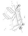
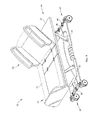
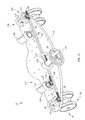
transport apparatuses 10 according to one embodiment of the current disclosure are shown inFIGs. 1 &2 . Thetransport apparatuses 10 can be used with many different apparatuses able to utilize a transport. However, for the sake of brevity thetransport apparatuses 10 are shown as being used in conjunction with apatient support apparatus 12. Thepatient support apparatus 12 can include a head section H1, where the head of a patient (not shown) can be positioned, and a foot section F1, where the feet of a patient (not shown) can be positioned. Thepatient support apparatus 12 can include a plurality oftransport apparatuses 10 and aframe 14 that can be supported by the plurality oftransport apparatuses 10. It should be appreciated that in some illustrative embodiments thepatient support apparatus 12 can support amattress 16. Thepatient support apparatus 12 can contact afloor 18 or other support surfaces including, but not limited to, ceramic flooring, wood flooring, metal flooring, concrete flooring, rubber flooring or mats, carpeting, ramps, vehicle surfaces, dirt, gravel, concrete, grass, sand, mud, or other surfaces that can be encountered when moving thepatient support apparatuses 12. - The
frame 14 can include alower frame 20 and anupper frame 22 connected to thelower frame 20 by aframe linkage 24 as shown inFIG. 1 . It should be appreciated that theframe linkage 24 can be alift mechanism 24 configured to move theupper frame 22 with respect to thelower frame 20. It should also be appreciated that theupper frame 22 can be stationary with respect to thelower frame 20. It should further be appreciated that thelower frame 20 can comprise one or more sections as shown inFIG. 10 . - The
lower frame 20 can include a plurality oflower frame bores 26 proximate the corners of thelower frame 20, as shown inFIG. 2 . Thelower frame bores 26 can extend substantially perpendicularly between the upward facingsurface 28 and the downward facingsurface 30 of thelower frame 20. Each of thelower frame bores 26 can retain acylindrical collar 32 therein. Thecollar 32 can include acollar bore 34 extending therethrough, and thecollar 32 can extend above and/or below the upward facingsurface 28 and the downward facingsurface 30 of thelower frame 20, respectively. It should be appreciated thatcollar 32 can be flush with the upward facingsurface 28 and/or the downward facingsurface 30. It should also be appreciated thatcollar 32 can be integrally formed withlower frame 20 as shown inFIGs. 7 and 8 . - The
collar 32 can retain aradial bearing 36 within thecollar bore 34 as shown inFIG. 2 . Theradial bearing 36 can be pressed within the collar bore 34 proximate the downward facingsurface 30 of thelower frame 20. It should be appreciated that theradial bearing 36 can be retained within thecollar bore 34 with an adhesive or retainer (not shown). Theradial bearing 36 can rotatably engage a portion of thetransport apparatuses 10 to maintain the concentric alignment of thetransport apparatuses 10 with thecollar bore 34 and can limit lateral movement. - At least one of the
frame 14 and a portion of thetransport apparatuses 10 can be moved with respect to one another between a first position or operating position and a second position or rotation resisting (brake) position. Thetransport apparatuses 10 can include anactuator assembly 38 and acaster assembly 40 as shown inFIG. 2 . Theactuator assembly 38 can include an actuatingcam shaft 42 and a plurality ofcam mounts 44. It should be appreciated that theactuator assembly 38 can alternatively include a linear actuator, a rotary actuator, a pneumatic actuator, a motor, a servomechanism, a hydraulic actuator, a manual crank, a lever, a foot pedal or other mechanical, electrical, or fluid actuation devices that can be configured to directly engage thecaster assembly 40 or thecam shaft 42 to move thecaster assembly 40 and/or thelower frame 20 with respect to one another. It should also be appreciated that theactuator assembly 38 can be configured to move thecaster assembly 40 and/or thelower frame 20 with respect to one another by rotating thecaster assembly 40 in a screw-like manner, for example, with respect to thelower frame 20. - The
cam shaft 42 can be rotatably retained within thecam mounts 44 and can extend betweenadjacent transport apparatuses 10 along the head section H1 and the foot section F1 of thelower frame 20, as shown inFIG. 1 , to synchronize movement of the head section H1 and the foot section F1lower frame 20 and/ortransport apparatuses 10. It should be appreciated that in alternative embodiments thecam shaft 42 can operate asingle transport apparatus 10, rather than extending between multiple apparatuses, in order to allow for independent operation of thetransport apparatuses 10 as shown inFIG. 9 . Thecam shaft 42 can be rotated by amotor 46 coupled to thelower frame 20 that can engage agear 48 coupled to thecam shaft 42 as shown inFIG. 1 . It should be appreciated thatmultiple motors 46 can be utilized to independently and/or simultaneously rotate thecam shaft 42 of eachactuator assembly 38 as shown inFIG. 10 . It should also be appreciated that a manual crank, a wheel, a lever, foot pedal or other manual actuation mechanism (not shown) can be used to rotate thecam shaft 42 or can directly engage thecaster assembly 40 to move thelower frame 20 and/or thecaster assembly 40 with respect to one another. - The
cam shaft 42 can include arecessed portion 50 that engages thecaster assembly 40 to move thecaster assembly 40 and/or theframe 14 with respect to one another as shown inFIG. 2 . It should be appreciated that thecam shaft 42 can alternatively include a raised cam portion (not shown). It should also be appreciated that thecam shaft 42 can be a crankshaft (not shown) that can pivotably couple with a portion of thecaster assembly 40.
It should be further appreciated that theactuator assembly 38 can include an inclined plane (not shown) instead of or in addition to thecam shaft 42, or a similar device adapted to move theframe 14 and thecaster assembly 40 with respect to one another. The recessedportion 50 can be a flat, cut-out portion or can be radially tapered according to the amount of control desired over the movement of thecaster assembly 40 with respect to theframe 14. It should be appreciated that the recessedportion 50 can not be tapered uniformly and can include raised cam portions (not shown). - The cam mounts 44 can be coupled to the upward facing
surface 28 of thelower frame 20 by a plurality of cam mount fasteners 52 as shown inFIG. 2 . The plurality of cam mount fasteners 52 can be bolts, screws, pins, adhesive, welds or other such fasteners, compounds, or combinations thereof. The cam mounts 44 can include alower cam mount 54 that can be coupled to the upward facingsurface 28 of thelower frame 20, an upper cam mount 56 that can be coupled to thelower cam mount 54, and a cam mount bore 58 extending therethrough. It should be appreciated that the cam mounts 44 can be a single structure with a cam mount bore 58 extending at least partially therewithin. It should also be appreciated that thelower cam mount 54 can be integrally formed with thelower frame 20. - The cam mount bores 58 can rotatably retain the
cam shaft 42 therewithin to maintain the alignment of thecam shaft 42 with respect to the lower frame bores 26 as shown inFIG. 2 . In order to reduce the amount of friction between thecam shaft 42 and the cam mount bores 58, thecam mount 44 can be at least partially composed of a bearing quality material, such as, nylon or similar low resistance materials. It should be appreciated that the cam mount bores 58 can be lubricated with oil, grease, graphite, or other lubricants. It should also be appreciated that the cam mount bore 58 can include a cam mount bearing (not shown) or bearing sleeve (not shown) that can be retained therewithin. - The
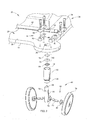
caster assembly 40 can be positioned proximate the downward facingsurface 30 of thelower frame 20 as shown inFIG. 2 . A portion of thecaster assembly 40 can be positioned within the collar bore 34 and can engage theradial bearing 36. Thecaster assembly 40 can include acaster shaft 60 oryolk 60, apuck 62, aretainer 64, and a plurality ofcaster wheel assemblies 66. It should be appreciated that thecaster assembly 40 can not include apuck 62 and thecaster shaft 60 can directly engage theactuator assembly 38. Thecaster shaft 60 can include apilot 68 at one end of thecaster shaft 60, aretainer groove 70, and acaster wheel interface 72 at the other end of thecaster shaft 60. - The
puck 62 can be positioned between theactuator assembly 38 and thecaster assembly 40 and can be movable within the collar bore 34 as shown inFIG. 2 . Thepuck 62 can be substantially the same diameter as the inner diameter of the collar bore 34 and can slidably engage the recessedportion 50 of thecam shaft 42, the collar bore 34, and/or thecaster shaft 60 to maintain the vertical and/or lateral orientation of thecaster assembly 40 with respect to theframe 14. Thepuck 62 can include abackup plate 74 and athrust bearing 76. It should be appreciated that thepuck 62 can alternatively include only the thrust bearing 76 as shown in the alternative embodiments ofFIGs. 5 &8 . It should also be appreciated thatpuck 62 can include one or more ball-bearings (not shown), wheels (not shown), or other rotating elements coupled with thecaster shaft 60 that can directly engage thecam shaft 42. It should further be appreciated that thepuck 62 can be a link (not shown) or a connecting rod (not shown) that can be movably coupled to thecam shaft 42 and/or thecaster shaft 60. Thepilot 68 can engage the thrust bearing 76 of thepuck 62 such that a portion of thepilot 68 can be positioned within the thrust bearing 76 to maintain concentric alignment of thethrust bearing 76 andcaster shaft 60 within the collar bore 34. - While the
puck 62 andactuator assembly 38 can be one way of raising and lowering theframe 14 to engage and disengage thetransport apparatus 10, many other embodiments are possible. For example, thetransport apparatus 10 might be moved to the operating position by stepping on or otherwise actuating a locking mechanism (not shown) which can increase the spacing between theframe 14 andtransport apparatus 10, such as, by forcing thecaster assemblies 40 downward. Thetransport apparatus 10 could later be moved to the second position by disengaging the locking mechanism (not shown) to thereby allow theframe 14 to rest on thetransport apparatus 10 and to provide frictional resistance between theframe 10 andtransport apparatus 10, resisting movement of thetransport apparatus 10 and subsequent movement of thepatient support apparatus 12. - The
retainer 64 can engage theretainer groove 70 and can be supported by a portion of theradial bearing 36 to removably retain thecaster shaft 60 within the collar bore 34 as shown inFIG. 2 . Theretainer 64 can facilitate the quick installation and removal/replacement of thecaster assemblies 40. It should be appreciated that theretainer 64 can be supported by a portion of the collar bore 34 to removably retain thecaster shaft 60 within the collar bore 34. It should also be appreciated that the collar bore 34 can include a retainer groove (not shown) that slidably engages and supports theretainer 64 to removably retain thecaster shaft 60 within the collar bore 34. It should be further appreciated that the collar bore 34 and thecaster shaft 60 can include threads (not shown) that engage one another to retain thecaster shaft 60 within the collar bore 34, which can negate the need for apuck 62 and/orradial bearing 36. Theretainer 64 can be a rubber o-ring, a retaining clip, retaining pin, or other known retaining devices. - The
caster wheel assembly 66 can include a plurality ofcaster wheels 78, a plurality ofcaster wheel shafts 80, and a plurality ofcaster wheel bearings 82 as shown inFIG. 2 . It should be appreciated that thecaster wheel assembly 66 can include only asingle caster wheel 78,caster wheel shaft 80, and caster wheel bearing 82 as shown inFIGs. 7-8 . It should also be appreciated that one or both of thecaster wheel shafts 80 and thecaster wheel bearings 82 can be integrally formed with thecaster wheel interface 72,caster shaft 60, or thecaster wheels 78. - The
caster wheels 78 can include anengagement surface 84 that can engage thefloor 18. Theengagement surface 84 can include afirst engagement side 86 and asecond engagement side 88. The downward facingsurface 30 of thelower frame 20 can frictionally contact one or both of thefirst engagement side 86 and thesecond engagement side 88. - The
caster wheel shafts 80 can be coupled to thecaster wheel interface 72 at an angle with respect to thecaster shaft 60 to orient thecaster wheels 78 such that they are at an angle with respect to thecaster shaft 60 and thelower frame 20 as shown inFIG. 2 . It should be appreciated that in alternative embodiments thecaster wheel shafts 80 can be coupled to thecaster wheel interface 72 perpendicularly with respect to thecaster shaft 60 to orient thecaster wheels 78 such that they are parallel with respect to thecaster shaft 60 as shown inFIGs. 5 & 6 . It should also be appreciated that a singlecaster wheel shaft 80 can be coupled with thecaster wheel interface 72 perpendicularly or at an angle with respect to thesingle caster wheel 78 such that it is parallel or at an angle with respect to thecaster shaft 60, respectively, as shown inFIGs. 7 & 8 . - The angular orientation of the
caster wheels 78 can assist in reducing the activation force required to move thepatient support apparatus 12 from a stationary position. The angular orientation can also increase the pressure interface area between thecaster wheels 78 and thefloor 18, and can help prevent quaking of thecaster wheels 78. Furthermore, the angular orientation can prevent damage to the portion of thecaster wheels 78 that interfaces with thefloor 18 since a different portion of thecaster wheels 78 is frictionally engaged by theframe 18 to resist rotation of thecaster wheels 78, which can result in affecting a brake application. It should be appreciated that a brake application can be affected, for example, through resistance ofwheel 78 rotation or through resistance of movement of atransport apparatus 10. - When the
transport apparatus 10 is in the operative position, the downward facingsurface 30 of thelower frame 20 can be spaced apart from the engagement surface 84 a distance D1 as shown inFIGs. 3 ,5 , and7 . When thetransport apparatus 10 is in the brake position, the downward facingsurface 30 of thelower frame 20 can be frictionally contacting theengagement surface 84 as shown inFIGs. 4 ,6 , and8 . It should be appreciated that when thewheels 78 are at an angle with respect to thecaster shaft 60 and thetransport apparatus 10 is in the first or operative position, the downward facingsurface 30 of thelower frame 20 can be spaced apart from thefirst engagement side 86 of theengagement surface 84 by the distance D1 as shown inFIG. 3 . It should also be appreciated that when thewheels 78 are at an angle with respect to thecaster shaft 60 and thetransport apparatus 10 is in the brake position, the downward facingsurface 30 of thelower frame 20 can be frictionally contacting thesecond engagement side 88 of theengagement surface 84 as shown inFIG. 4 . - The
caster wheel bearings 82 can couple with thecaster wheel shafts 80 and can be removably retained within thecaster wheels 78. It should be appreciated that thecaster wheel bearings 82 can be integrally formed with thecaster wheels 78 or thecaster wheel shafts 80. Thecaster wheel bearings 82 can be radial bearings, thrust bearings, polymeric sleeves, or other bearing structures or materials adapted to withstand lateral and radial load bearing forces. - To install the
transport apparatuses 10 in theframe 14, thecaster assemblies 40 can be inserted into thecollars 32 such that thecaster shafts 60 and theretainers 64 are positioned within the collar bores 34 and retained therein by the engagement of theretainer 64 and theradial bearing 36. The installation can not require special tools. Since installation of thetransport apparatuses 10 can occur upon delivery of thepatient support apparatus 12 to a customer,transport apparatuses 10 and/or replacements thereof can be sold separately and/or shipped separately. Additionally,patient support apparatuses 12 can be shipped to customers without thetransport apparatuses 10 installed therein to provide for additional space for morepatient support apparatuses 12 to be included in the shipment. - Describing now the operation of these various illustrative embodiments, the
transport apparatus 10 can be positioned initially in the operating position relative theframe 14 as shown inFIGs. 3 ,5 , and7 , such that thepatient support apparatus 12 is freely movable with respect to thefloor 18. In this position, thecam shafts 42 can be positioned at top-dead-center such that thepuck 62 does not substantially engage the recessedportion 50 of thecam shafts 42, and thecaster wheels 78 are spaced apart a distance D 1 from the downward facingsurface 30 of thelower frame 20. It should be appreciated that distance D1 can be the maximum distance between thecaster wheels 78 and the downward facingsurface 30 of thelower frame 20, and can differ depending on the orientation of thecaster wheels 78 with respect to thecaster shaft 60 and the configuration of the recessedportion 50 of thecam shafts 42. - To resist rotation of the
caster wheels 78, which can result in affecting a brake application, thecam shafts 42 can be rotated from approximately top-dead-center to approximately bottom-dead center by themotor 46 engaging thegear 48 to move thetransport apparatus 10 to a second position or rotation resisting (brake) position with respect to theframe 14 as shown inFIGs. 4 ,6 , and8 . As thecam shafts 42 rotate, thepuck 62 can slidably engage the recessedportion 50 of thecam shafts 42 and move thelower frame 20 and thecaster wheels 78 toward one another, thereby decreasing the distance D1 therebetween. Once thecam shafts 42 are at approximately bottom-dead-center, the downward facingsurface 30 of thelower frame 20 can be frictionally engage theengagement surface 84 of thecaster wheels 78, thereby resisting rotation of thecaster wheels 78, which can result in affecting a brake application. - A
transport apparatus 110 according to another illustrative embodiment of the current disclosure is depictedFIGs. 10-13 . Apatient support apparatus 112 can include a plurality oftransport apparatuses 110, alower frame 114, and asynchronizing system 116. The synchronizingsystem 116 can synchronize the movement of thetransport apparatuses 110 so that the downward facingsurface 30 of thelower frame 114 can engage theengagement surface 84 of thetransport apparatuses 110 simultaneously. It should be appreciated that thesynchronizing system 116 can be used to synchronize the movement of fourtransport apparatuses 110 as shown inFIG. 10 . It should also be appreciated that thesynchronizing system 116 can be used to synchronize two of thetransport apparatuses 110 as shown inFIG. 11 . - The
transport apparatuses 110 can include anactuator apparatus 118, apuck 62, and acaster assembly 40 as shown inFIGs. 10-13 . Theactuator apparatus 118 can include acam shaft 120 and a plurality of cam mounts 44 coupled to the upward facingsurface 28 of thelower frame 114. Thecam shaft 120 can be rotatably retained within a cam mount bore 58 of the cam mounts 44. One end of thecam shaft 120 can include acam shaft gear 122 mounted thereon that can engage thesynchronizing system 116. It should be appreciated that the end of thecam shaft 120 can include teeth (not shown) formed therein instead of thegear 122. - The synchronizing
system 116 can include arack 124 orlongitudinal member 124 that can haveteeth 126 thereon, a plurality of tubularlongitudinal members 128, and a synchronizingshaft 130 that can include asynchronizing gear 132 mounted thereon and that can be positioned within one of thelongitudinal members 128 as shown inFIGs. 10-13 .
The plurality oflongitudinal members 124 can extend between sections of thelower frame 114. It should be appreciated that thelower frame 114 can be a singlelower frame 114 section withlongitudinal members 124 extending there along. - The
rack 124 can extend between a pair oftransport apparatuses 110 and can slidably engage the upward facingsurface 28 of thelower frame 114 such that therack 124 can be substantially perpendicular thecam shafts 120 and/or thelongitudinal members 128 as shown inFIGs. 10-13 . It should be appreciated that therack 124 can engage a channel (not shown) in thelower frame 114 to maintain the substantially perpendicular orientation of therack 124 with respect to thecam shafts 120 and/or thelongitudinal members 128.
Theteeth 126 can engage the cam shaft gears 122 that can be coupled to thecam shafts 120 and/or synchronizinggears 132 that can be coupled to the synchronizingshaft 130. - The
rack 124 can be moved between the pair oftransport apparatuses 110 by amotor 134 that can be coupled to thelower frame 114 by amotor mount 136 as shown inFIGs. 10-13 . Themotor 134 can engage amotor gear 138 that can be coupled to therack 124. It should be appreciated that therack 124 can be moved between the pair oftransport apparatuses 110 by a manual crank 140 as shown in the embodiment ofFIG. 13 , a lever, a wheel, a cam, a foot pedal, or other manual actuation devices or combinations thereof. It should also be appreciated that therack 124 can be moved between the pair oftransport apparatuses 110 by a linear actuator, a rotary actuator, a pneumatic actuator, a servomechanism, a hydraulic actuator, or other mechanical, electrical, or fluid actuation devices or combinations thereof. - The
longitudinal members 128 can include a longitudinal member bore 142 that can extend between thelower frame 114 sections as shown inFIGs. 10-13 . Thelongitudinal members 128 can be coupled to thelower frame 114 sections by longitudinal member mounts 144. Longitudinal member mounts 144 can include a longitudinal member mount bore 146 that can retain thelongitudinal members 128 therein. It should be appreciated that thelongitudinal members 128 can rotate with respect to the longitudinal member mounts 144. Longitudinal member mounts 144 can be coupled to the upward facingsurface 28 of thelower frame 114 with fasteners (not shown). It should be appreciated that the longitudinal member mounts 144 can be coupled to the upward facingsurface 28 with adhesive or integrally formed with thelower frame 114. - The synchronizing
shaft 130 can extend through one of thelongitudinal members 128 and between theracks 124 located on both of thelower frame 114 sections as shown inFIGs. 10-13 . The synchronizingshaft 130 can be positioned generally concentrically within thelongitudinal member 128 and can rotate with respect to thelongitudinal member 128. It should be appreciated thatlongitudinal members 128 can include at least one radial bearing (not shown) that can be positioned within the longitudinal member bore 142 to concentrically locate the synchronizingshaft 130 and facilitate rotation thereof. It should also be appreciated that thelongitudinal members 128 can include a bearing sleeve (not shown) or can be lubricated with oil, grease, graphite, or other low-friction lubricants. - In operation, the
transport apparatuses 110 on both of thelower frame 114 sections can be initially positioned in the operating position relative thelower frame 114 such that thepatient support apparatus 112 is freely movable with respect to the floor 11, which can be similar to the first position shown inFIGS. 3 ,5 , &7 . In this position, thecam shafts 120 can be positioned at approximately top-dead-center such that thepucks 62 do not substantially engage the recessedportions 50 of thecam shafts 120, and thecaster wheels 78 are spaced apart a distance D1 from the downward facingsurface 30 of thelower frame 114. - To resist rotation of the
caster wheels 78, which can result in affecting a brake application , thecam shafts 120 can be rotated from approximately top-dead-center to approximately bottom-dead center by themotor 134 coupled to one of the sections of thelower frame 114 to move at least one of thetransport apparatuses 110 and thelower frame 114 with respect to one another to the brake position, which can be similar to the second position shown inFIGs. 4 ,6 , and8 . Themotor 134 can rotate amotor gear 138 coupled with therack 124 to move therack 124 with respect to thetransport apparatuses 110. As therack 124 moves with respect to thecam shafts 120 andlongitudinal members 128, theteeth 126 can cause the cam shaft gears 122 and the synchronizing gears 132 to rotate. Rotation of the cam shaft gears 122 and the synchronizing gears 132 can cause thecam shafts 120 and synchronizingshaft 130 to rotate. - As the synchronizing
shaft 130 rotates, the synchronizing gear132 mounted on the other end of the synchronizingshaft 130 that engages therack 124 and slidably engages the other section of thelower frame 114 can rotate. The rotation of the synchronizing gear132 can cause therack 124 to move with respect to thetransport apparatuses 110 coupled to the second section of thelower frame 114. Theteeth 126 on therack 124 can engage and cause the cam shaft gears 122 to rotate, which can cause thecam shafts 120 to rotate. As thecam shafts 120 are rotated, thepuck 62 can slidably engage the recessedportion 50 of thecam shaft 120 and move at least one of thelower frame 114 and thecaster wheels 78 toward one another, thereby reducing the distance D1 therebetween. Once thecam shaft 120 is at approximately bottom-dead-center, the downward facingsurface 30 of thelower frame 114 can be frictionally engaged with thecaster wheels 78, thereby resisting rotation of thecaster wheels 78, which can result in affecting a brake application. - A
transport apparatus 210 according to yet another illustrative embodiment of the current disclosure is shown inFIG. 14 . Apatient support apparatus 212 can include a plurality oftransport apparatuses 210, alower frame 114, and asynchronizing system 214. - The
transport apparatuses 210 can include anactuator apparatus 216, apuck 62, and acaster assembly 40 as shown inFIG. 14 . Theactuator apparatus 216 can include acam shaft 120 and a plurality of cam mounts 44 that can be coupled to the upward facingsurface 28 of thelower frame 114. One end of thecam shaft 120 can include acam shaft gear 218 mounted thereon that can engage thesynchronizing system 214. The cam shaft gears 218 can be generally circular and can include apin 220 that can protrude from the surface of the cam shaft gears 218 proximate the edges of the cam shaft gears 218. - The synchronizing
system 214 can include a plurality oflinks 222 with a plurality of pin holes 224 therein, a plurality oflongitudinal members 128 that can extend between the sections of thelower frame 114, and a synchronizingshaft 130 that can have asynchronizing gear 226 with apin 228 as shown inFIG. 14 . The pin holes 224 can engage the pins 220,228 and can removably couple thelinks 222 to the cam shaft gears 218 and the synchronizing gears 226. It should be appreciated that the pins 220,228 can be retained within the pin holes 224. The pin holes 224 can be generally located proximate the ends and centers of thelinks 222. It should be appreciated that the pin holes 224 can be located anywhere along thelinks 222 to engage the pins 220,228. - The
links 222 can be moved by a manual crank 140 coupled to thelower frame 114 by acrank mount 230. The crank 140 can engage a crankgear 232 withpins 234 that can couple thecrank gear 232 to thelinks 222 as shown inFIG. 14 . It should be appreciated that thelinks 222 can be moved by amotor 134, a pneumatic linear actuator, a pneumatic rotary actuator, a motor, a servomechanism, a hydraulic cylinder, or other mechanical, electrical, or fluid actuation devices, or combinations thereof. It should also be appreciated that thelinks 222 can be moved by a lever, a cam, a foot pedal or other manual actuation devices or combinations thereof. - In operation, the
transport assemblies 210 on both of thelower frame 114 can be initially positioned in the operating position relative thelower frame 114 such that thepatient support apparatus 212 is freely movable with respect to thefloor 18, which can be similar to the first position shown inFIGs. 3 ,5 , &7 . In this position, thecam shafts 120 can be positioned at approximately top-dead-center such that thepucks 62 do not substantially engage the recessedportions 50 of thecam shafts 120, and thecaster wheels 78 are spaced apart a distance D1 from the downward facingsurface 30 of thelower frame 114. - To resist rotation of the
caster wheels 78, which can result in affecting a brake application, thecam shafts 120 can be rotated from approximately top-dead-center to approximately bottom-dead center by the manual crank 140 coupled to one section of thelower frame 114 to move at least one of thetransport apparatuses 210 and thelower frame 114 with respect to one another to the brake position with respect to thelower frame 114, which can be similar to the second position shown inFIGs. 4 ,6 , and8 . The manual crank 140 can rotate thecrank gear 232 coupled with thelinks 222 to move thelinks 222 between thetransport apparatuses 210. As thelinks 222 move, the cam shaft gears 218 and thesynchronizing gear 226 can rotate, thereby causing thecam shafts 120 and synchronizingshaft 130 to rotate. - As the synchronizing
shaft 130 rotates, thesynchronizing gear 226 engaging the other set oflinks 222 proximate the other section of thelower frame 114 can rotate. The rotation of thesynchronizing gear 226 can cause thelinks 222 to move between thetransport apparatuses 210 coupled to the other section of thelower frame 114. The pins 220,228 engaging the pin holes 224 of thelinks 222 can be moved as thelinks 222 move, thereby causing thecam shafts 120 to rotate. As thecam shafts 120 are rotated, thepuck 62 can begin to slidably engage the recessedportion 50 of thecam shaft 120 and move at least one of thelower frame 114 and thecaster wheels 78 with respect to one another. Once thecam shaft 120 is at approximately bottom-dead-center, the downward facingsurface 30 of thelower frame 114 can be frictionally engaged with thecaster wheels 78, thereby resisting rotation of thecaster wheels 78, which can result in affecting a brake application. - Many other embodiments of the present disclosure are also envisioned. For example, an
apparatus frame 14 and atransport assembly frame 14. Thetransport assembly frame 14 between a transport position and a brake position. A portion of theframe 14 frictionally engages a portion of thetransport assembly frame 14. The portion of theframe 14 is disengaged from the portion of thetransport assembly frame 14. - In another example, a
patient support apparatus frame 14, anactuator assembly caster assembly 40. Theactuator assembly frame 14. Thecaster assembly 40 supports theframe 14. A portion of theactuator assembly caster assembly 40 and theframe 14 relative one another to at least one of engage and disengage a portion of thecaster assembly 40 and a portion of theframe 14 to selectively resist rotation of a portion of thecaster assembly 40 with respect to theframe 14. - In yet another example, a
support apparatus frame 14 supported by atransport apparatus transport apparatus rotational element 78 and is in a first position relative theframe 14. Thetransport apparatus frame 14. Therotational element 78 of thetransport apparatus frame 14 in the second position to resist rotation of therotational element 78. - Any theory, mechanism of operation, proof, or finding stated herein is meant to further enhance understanding of principles of the present disclosure and is not intended to make the present disclosure in any way dependent upon such theory, mechanism of operation, illustrative embodiment, proof, or finding. It should be understood that while the use of the word preferable, preferably or preferred in the description above indicates that the feature so described can be more desirable, it nonetheless can not be necessary and embodiments lacking the same can be contemplated as within the scope of the disclosure, that scope being defined by the claims that follow. In reading the claims it is intended that when words such as "a," "an," "at least one," "at least a portion" are used there is no intention to limit the claim to only one item unless specifically stated to the contrary in the claim. When the language "at least a portion" and/or "a portion" is used the item can include a portion and/or the entire item unless specifically stated to the contrary. While embodiments of the disclosure have been illustrated and described in detail in the drawings and foregoing description, the same are to be considered as illustrative and not restrictive in character, it being understood that only the selected embodiments have been shown and described.
Claims (15)
- An apparatus (12, 112, 212) comprising:a frame (14),and a transport assembly (10, 110, 210) supporting the frame (14), the transport assembly (10, 110, 210) configured to selectively move relative to the frame (14) between a transport position and a brake position, wherein a portion of the frame (14) frictionally engages a portion of the transport assembly (10, 110, 210) in the brake position to affect a brake application that resists the transportation of the frame (14), and wherein the portion of the frame (14) is disengaged from the portion of the transport assembly (10, 110, 210) in the transport position to allow for transportation of the frame (14).
- The apparatus (12, 112, 212) of claim 1, wherein the transport assembly (10, 110, 210) includes an actuator assembly (38, 118, 216) coupled to the frame (14) and a caster assembly (40) removably coupled to the frame 14, a portion of the caster assembly (40) engaging a portion of the actuator assembly (38, 118, 216), the portion of the actuator assembly (38, 118, 216) being configured to move the caster assembly (40) with respect to the frame (14).
- The apparatus (12, 112, 212) of claim 2, wherein the actuator assembly (38, 118, 216) includes a cam shaft (42, 120) that rotatably engages the portion of the caster assembly (40) to move the caster assembly (40) with respect to the frame (14) as the cam shaft (42, 120) is rotated, the cam shaft (42, 120) including at least one of a recessed portion and a raised portion that engages the caster assembly (40).
- The patient support apparatus (12, 112, 212) of either claim 2 or claim 3, wherein the caster assembly (40) includes a caster shaft (60) and a wheel (78) coupled to the caster shaft (60), wherein the wheel (78) is substantially parallel to the caster shaft (60).
- The patient support apparatus (12, 112, 212) of any one of claims 2 to 4, wherein the frame (14) includes a bore (26), a portion of the caster assembly (40) being positioned within the bore (26), a retaining element (64) being configured to couple with the portion of the caster assembly (40) positioned within the bore (26) and configured to couple with a portion of the bore (26) to removably retain the portion of the caster assembly (40) within the bore (26).
- The patient support apparatus (12, 112, 212) of any one of claims 2 to 5, wherein the actuator assembly (38, 118, 216) includes an actuator selected from the group of actuators consisting of a pneumatic actuator, a linear actuator, a rotary actuator, a hydraulic actuator, a motor, a servomechanism, a manual crank, a lever, and a foot pedal.
- The patient support apparatus (12, 112, 212) of any one of claims 2 to 6 further comprising a synchronization system (116, 214) including:a longitudinal member (124, 222);a first gear (122, 218) coupled to an end of the actuator assembly (38, 118, 216);and second gear (122, 218) coupled to an end of a second actuator assembly (38, 118, 216) engaging a second caster assembly (40), the first gear (122, 218) and the second gear (122, 218) engaging the longitudinal member (124, 222) to coordinate movement of the caster assembly (40), the second caster assembly (40), and the frame (14) with respect to one another.
- The patient support apparatus (12, 112, 212) of claim 7 further comprising:a second longitudinal member (124, 222);a synchronizing member (130) extending between about the longitudinal member (124, 222) and the second longitudinal member (124, 222);and a third gear (136, 226) coupled with an end of the synchronizing member (130), the third gear (136, 226) engaging the second longitudinal member (124, 222), the synchronizing member (130) being configured to coordinate movement of the caster assembly (40), the second caster assembly (40), a third caster assembly (40), and the frame (14) with respect to one another.
- The patient support apparatus (12, 112, 212) of claim 7, wherein the longitudinal member (124) slidably engages the frame (14) and includes a plurality of teeth (126) disposed over a portion of the longitudinal member (124), the teeth (126) configured to engage the first gear (122, 218) and second gear (122, 218).
- The patient support apparatus (12, 112, 212) of claim 7, wherein the longitudinal member (222) includes a plurality of holes (224) therein and the first gear (122, 218) and second gear (122, 218) include pins (220, 228) extending therefrom that are configured to engage the holes (224) to couple the first gear (122, 218) and second gear (122, 218) to the longitudinal member (222).
- The apparatus (12, 112, 212) of claim 1, wherein the transport assembly (10, 110, 210) includes a rotational element (78) with an engagement surface (84), wherein the engagement surface (84) is configured to contact a support surface (18) in the transport position and wherein the engagement surface (84) is configured to frictionally contact the portion of the frame (14) and the support surface (18) in the brake position.
- The apparatus (12, 112, 212) of claim 6, wherein the rotational element (78) is aligned angularly with respect to the frame (12), and wherein the engagement surface (84) includes a first portion (86) and a second portion (88), the first portion (86) of the engagement surface (84) being configured to contact the support surface (18) and the second portion (88) of the engagement surface (84) being configured to frictionally contact the portion of the frame (14), the first portion (86) and the second portion (88) are different portions of the engagement surface (84).
- The apparatus (12, 112, 212) of claim 12, wherein the first portion (86) does not contact the frame (14) in the brake position and the second portion (88) does not contact the support surface (18) in the transport position.
- The patient support apparatus (12, 112, 212) of any preceding claim, wherein the frame (14) includes a lower frame (20, 114), a linkage (24) coupled to the lower frame (20, 114), and an upper frame (22) supported above the lower frame (20, 114) on the linkage (24) and adapted to move with respect to the lower frame (20, 114).
- The patient support apparatus (12, 112, 212) of any preceding claim, wherein the upper frame (22) includes a head end H1 and a foot end F1 adapted to articulate with respect to one another.
Applications Claiming Priority (1)
| Application Number | Priority Date | Filing Date | Title |
|---|---|---|---|
| US6147308P | 2008-06-13 | 2008-06-13 |
Publications (2)
| Publication Number | Publication Date |
|---|---|
| EP2133056A2 true EP2133056A2 (en) | 2009-12-16 |
| EP2133056A3 EP2133056A3 (en) | 2011-05-04 |
Family
ID=41110419
Family Applications (1)
| Application Number | Title | Priority Date | Filing Date |
|---|---|---|---|
| EP09251543A Withdrawn EP2133056A3 (en) | 2008-06-13 | 2009-06-12 | Transport apparatus |
Country Status (2)
| Country | Link |
|---|---|
| US (1) | US8590074B2 (en) |
| EP (1) | EP2133056A3 (en) |
Families Citing this family (14)
| Publication number | Priority date | Publication date | Assignee | Title |
|---|---|---|---|---|
| US9498397B2 (en) | 2012-04-16 | 2016-11-22 | Allen Medical Systems, Inc. | Dual column surgical support system |
| DE102014202033B4 (en) * | 2014-02-05 | 2017-07-06 | Siemens Healthcare Gmbh | Mobile medical device and method for controlling movement of the mobile medical device |
| US9603764B2 (en) | 2014-02-11 | 2017-03-28 | Medline Industries, Inc. | Method and apparatus for a locking caster |
| US10492973B2 (en) | 2015-01-05 | 2019-12-03 | Allen Medical Systems, Inc. | Dual modality prone spine patient support apparatuses |
| US9655793B2 (en) * | 2015-04-09 | 2017-05-23 | Allen Medical Systems, Inc. | Brake release mechanism for surgical table |
| US10363189B2 (en) | 2015-10-23 | 2019-07-30 | Allen Medical Systems, Inc. | Surgical patient support for accommodating lateral-to-prone patient positioning |
| US10561559B2 (en) | 2015-10-23 | 2020-02-18 | Allen Medical Systems, Inc. | Surgical patient support system and method for lateral-to-prone support of a patient during spine surgery |
| US10548793B2 (en) | 2016-06-14 | 2020-02-04 | Allen Medical Systems, Inc. | Pinless loading for spine table |
| NL2018043B1 (en) * | 2016-12-22 | 2018-06-29 | Prevas Ergonomie B V | Tool for disabled people |
| US11213448B2 (en) | 2017-07-31 | 2022-01-04 | Allen Medical Systems, Inc. | Rotation lockout for surgical support |
| US10806653B2 (en) | 2017-12-21 | 2020-10-20 | Stryker Corporation | Patient transport apparatus with electro-mechanical braking system |
| US11202731B2 (en) | 2018-02-28 | 2021-12-21 | Allen Medical Systems, Inc. | Surgical patient support and methods thereof |
| US11471354B2 (en) | 2018-08-30 | 2022-10-18 | Allen Medical Systems, Inc. | Patient support with selectable pivot |
| USD921411S1 (en) * | 2019-03-29 | 2021-06-08 | Stryker Corporation | Endboard |
Citations (4)
| Publication number | Priority date | Publication date | Assignee | Title |
|---|---|---|---|---|
| US4489449A (en) * | 1981-02-06 | 1984-12-25 | Simmons Universal Corporation | Trauma care wheeled stretcher |
| US5112044A (en) * | 1990-10-22 | 1992-05-12 | Dubats Barbara A | Perambulating therapeutic support |
| EP0846457A2 (en) * | 1996-12-03 | 1998-06-10 | Hill-Rom, Inc. | Long term care bed controls |
| EP1818037A2 (en) * | 2006-02-11 | 2007-08-15 | Völker AG | Bed, in particular hospital or home care bed |
Family Cites Families (42)
| Publication number | Priority date | Publication date | Assignee | Title |
|---|---|---|---|---|
| US204050A (en) | 1878-05-21 | Improvement in water-wheel gates | ||
| US320365A (en) | 1885-06-16 | Huxhum p | ||
| US3237940A (en) * | 1963-10-22 | 1966-03-01 | Auline S Johnson | Safety brake casters for walking aid |
| US4385414A (en) | 1980-10-06 | 1983-05-31 | Joerns Furniture Company | Caster for adjustable beds and the like |
| US4339842A (en) | 1980-10-06 | 1982-07-20 | Stewart-Warner Corporation | Combination caster and fixed support |
| US4494272A (en) | 1981-07-21 | 1985-01-22 | Natsuo Morita | Reversible caster device having brake mechanism |
| US4646371A (en) | 1986-02-03 | 1987-03-03 | Harris-Hub Company, Inc. | Bed frame |
| US4828208A (en) | 1986-12-09 | 1989-05-09 | Joerns Healthcare, Inc. | Vertically adjustable table with retractable caster assembly |
| US5042622A (en) | 1990-05-22 | 1991-08-27 | Leonard Smith | Shopping cart foot brake assembly |
| US5566788A (en) | 1995-02-24 | 1996-10-22 | Ephtec, Inc. | Shopping cart brake assembly |
| PT877590E (en) | 1995-12-18 | 2003-08-29 | Alliance Invest Ltd | THERAPEUTIC DEVICE |
| US6874181B1 (en) | 1995-12-18 | 2005-04-05 | Kci Licensing, Inc. | Therapeutic bed |
| US6351861B1 (en) * | 1998-05-29 | 2002-03-05 | Hill-Rom Services, Inc. | Bed frame |
| JPH10201794A (en) | 1997-01-23 | 1998-08-04 | Exedy Corp | Vehicle using ball transfer with brake |
| US6260220B1 (en) | 1997-02-13 | 2001-07-17 | Orthopedic Systems, Inc. | Surgical table for lateral procedures |
| US6240579B1 (en) * | 1998-01-07 | 2001-06-05 | Stryker Corporation | Unitary pedal control of brake and fifth wheel deployment via side and end articulation with additional unitary pedal control of height of patient support |
| WO2000000152A1 (en) | 1998-06-26 | 2000-01-06 | Hill-Rom, Inc. | Proning bed |
| WO2000046046A1 (en) | 1999-02-08 | 2000-08-10 | Kayaba Kogyo Kabushiki Kaisha | Caster |
| AU4368100A (en) | 1999-04-21 | 2000-11-02 | Vincent L. Babson | Proning bed |
| US6269499B1 (en) | 1999-06-29 | 2001-08-07 | General Electric Company | Multi-axis planar mechanism for a positioner patient platform |
| US6219881B1 (en) | 1999-10-28 | 2001-04-24 | Cheng-Kan Wen | Brake for caster |
| US6568031B1 (en) * | 2000-03-03 | 2003-05-27 | Finger Lakes Intellectual Property, Llc | Caster assembly for a bed frame member or furniture |
| US20050060840A1 (en) | 2000-03-03 | 2005-03-24 | Polevoy Richard S. | Caster system used with wooden or plastic legs for furniture |
| US6279199B1 (en) | 2000-06-13 | 2001-08-28 | Ross Design & Engineering, Inc. | Vertically adjustable caster |
| WO2002005740A2 (en) | 2000-07-14 | 2002-01-24 | Hill-Rom Services, Inc. | Pulmonary therapy apparatus |
| US6640363B1 (en) | 2000-10-16 | 2003-11-04 | Ge Medical Systems Global Technology Company, Llc | Mobile imaging table pivot mechanism |
| US6550100B2 (en) | 2001-02-08 | 2003-04-22 | Waxman Industries, Inc. | Caster assembly with multi-position support pieces |
| JP3996746B2 (en) | 2001-07-13 | 2007-10-24 | 株式会社ナンシン | Caster braking structure |
| US6865775B2 (en) | 2001-09-05 | 2005-03-15 | Hill-Rom Services, Inc. | Hospital bed caster apparatus |
| DE10229931A1 (en) | 2002-07-04 | 2004-01-15 | Wanzl Metallwarenfabrik Gmbh | Track roller for shopping and transport trolleys |
| JP2004082994A (en) | 2002-08-28 | 2004-03-18 | Nippon Clean Engine Lab Co Ltd | Brake device of caster |
| US7017228B2 (en) | 2002-10-02 | 2006-03-28 | Harlan Silverstein | Pneumatic locking swivel caster |
| MXPA04001513A (en) | 2004-02-17 | 2005-08-19 | Ciateq A C | Rotating therapeutic bed. |
| JP2006011302A (en) | 2004-06-29 | 2006-01-12 | Kyocera Mita Corp | Image forming apparatus |
| US20060010646A1 (en) | 2004-07-14 | 2006-01-19 | Bushey Dennis J | Low profile caster assembly |
| US20060075600A1 (en) | 2004-10-12 | 2006-04-13 | Dominic Dennis P | Vertically adjustable caster |
| US7350269B2 (en) | 2004-10-12 | 2008-04-01 | Dennis Paul Dominic | Adjustable caster and leveling assembly |
| US7182178B2 (en) | 2004-12-22 | 2007-02-27 | Ching-Sung Lin | Brake caster with stroke adjustment mechanism |
| US7159278B2 (en) | 2005-02-24 | 2007-01-09 | Yale Security Inc. | Caster |
| US20070080030A1 (en) | 2005-10-06 | 2007-04-12 | Sunrise Medical Hhg Inc. | Brake assembly for beds |
| DE102007039208A1 (en) | 2006-11-07 | 2008-05-08 | Tente Gmbh & Co. Kg | Double roller with two wheels and roller with one impeller |
| FR2916332B1 (en) | 2007-05-22 | 2012-01-27 | Home Medical Service Hms | BED EQUIPPED WITH CASTERS |
-
2009
- 2009-06-12 EP EP09251543A patent/EP2133056A3/en not_active Withdrawn
- 2009-06-15 US US12/484,345 patent/US8590074B2/en not_active Expired - Fee Related
Patent Citations (4)
| Publication number | Priority date | Publication date | Assignee | Title |
|---|---|---|---|---|
| US4489449A (en) * | 1981-02-06 | 1984-12-25 | Simmons Universal Corporation | Trauma care wheeled stretcher |
| US5112044A (en) * | 1990-10-22 | 1992-05-12 | Dubats Barbara A | Perambulating therapeutic support |
| EP0846457A2 (en) * | 1996-12-03 | 1998-06-10 | Hill-Rom, Inc. | Long term care bed controls |
| EP1818037A2 (en) * | 2006-02-11 | 2007-08-15 | Völker AG | Bed, in particular hospital or home care bed |
Also Published As
| Publication number | Publication date |
|---|---|
| US8590074B2 (en) | 2013-11-26 |
| EP2133056A3 (en) | 2011-05-04 |
| US20090307844A1 (en) | 2009-12-17 |
Similar Documents
| Publication | Publication Date | Title |
|---|---|---|
| EP2133056A2 (en) | Transport apparatus | |
| US6820294B2 (en) | Linkage for lift/lowering control for a patient supporting platform | |
| US8789662B2 (en) | Wheeled carriage with brake lock system | |
| US10358876B2 (en) | Method and apparatus for transporting and steering a heavy load | |
| CA2930716C (en) | A movable cover for covering a pit | |
| JP5039699B2 (en) | Improvement of slide support or improvement regarding slide support | |
| US7992239B2 (en) | Laterally rotating patient support apparatus | |
| US7832528B1 (en) | Brake mechanism for operating table | |
| US5031869A (en) | Control assembly for chair height adjustment | |
| CA2651926A1 (en) | Wear compensating device for a brake device, and brake device | |
| US20190125599A1 (en) | Seat positioning system for a wheelchair | |
| US9737981B2 (en) | Universal joint dismantling tool | |
| US20100051884A1 (en) | Infinitely Adjustable and Constrainable Movable Structure for a Vehicle Lift | |
| WO2016062841A1 (en) | Device for adjusting the height of a first part relative to a second part, a retrofit kit for such a device, and a height-adjustable system comprising a plurality of such devices | |
| US4076216A (en) | Hoist mechanism | |
| CN114073371A (en) | Bedside table | |
| JP3028343B2 (en) | Adjustable bed with mechanical jack | |
| EP3009728B1 (en) | Retaining element for stand device and correspondingly formed components | |
| WO2018047071A1 (en) | An improved turntable. | |
| CN101836007B (en) | Brake caliper parking device, brake caliper and disc brake | |
| US8991281B2 (en) | Adjustable foot pedal, linkage, and method for actuating a hydraulic cylinder | |
| US8550433B2 (en) | Adjustable column system and method | |
| CN114799831A (en) | Automatic press-fitting table for bearing manufacturing | |
| JPH0647743U (en) | Brake actuator with automatic adjustment device | |
| US20210394558A1 (en) | Braking assembly for a caster base |
Legal Events
| Date | Code | Title | Description |
|---|---|---|---|
| PUAI | Public reference made under article 153(3) epc to a published international application that has entered the european phase |
Free format text: ORIGINAL CODE: 0009012 |
|
| AK | Designated contracting states |
Kind code of ref document: A2 Designated state(s): AT BE BG CH CY CZ DE DK EE ES FI FR GB GR HR HU IE IS IT LI LT LU LV MC MK MT NL NO PL PT RO SE SI SK TR |
|
| PUAL | Search report despatched |
Free format text: ORIGINAL CODE: 0009013 |
|
| AK | Designated contracting states |
Kind code of ref document: A3 Designated state(s): AT BE BG CH CY CZ DE DK EE ES FI FR GB GR HR HU IE IS IT LI LT LU LV MC MK MT NL NO PL PT RO SE SI SK TR |
|
| AX | Request for extension of the european patent |
Extension state: AL BA RS |
|
| 17P | Request for examination filed |
Effective date: 20111104 |
|
| RAP1 | Party data changed (applicant data changed or rights of an application transferred) |
Owner name: HILL-ROM SERVICES, INC. |
|
| 17Q | First examination report despatched |
Effective date: 20151021 |
|
| RIC1 | Information provided on ipc code assigned before grant |
Ipc: A61G 1/02 20060101ALN20160621BHEP Ipc: A61G 7/012 20060101ALN20160621BHEP Ipc: B62B 5/04 20060101ALN20160621BHEP Ipc: A61G 7/08 20060101AFI20160621BHEP |
|
| STAA | Information on the status of an ep patent application or granted ep patent |
Free format text: STATUS: THE APPLICATION IS DEEMED TO BE WITHDRAWN |
|
| 18D | Application deemed to be withdrawn |
Effective date: 20170209 |