EP2133662A2 - Methods and system of navigation using terrain features - Google Patents
Methods and system of navigation using terrain features Download PDFInfo
- Publication number
- EP2133662A2 EP2133662A2 EP09162088A EP09162088A EP2133662A2 EP 2133662 A2 EP2133662 A2 EP 2133662A2 EP 09162088 A EP09162088 A EP 09162088A EP 09162088 A EP09162088 A EP 09162088A EP 2133662 A2 EP2133662 A2 EP 2133662A2
- Authority
- EP
- European Patent Office
- Prior art keywords
- terrain
- terrain features
- processing unit
- navigation
- features
- Prior art date
- Legal status (The legal status is an assumption and is not a legal conclusion. Google has not performed a legal analysis and makes no representation as to the accuracy of the status listed.)
- Granted
Links
Images


Classifications
-
- G—PHYSICS
- G01—MEASURING; TESTING
- G01C—MEASURING DISTANCES, LEVELS OR BEARINGS; SURVEYING; NAVIGATION; GYROSCOPIC INSTRUMENTS; PHOTOGRAMMETRY OR VIDEOGRAMMETRY
- G01C21/00—Navigation; Navigational instruments not provided for in groups G01C1/00 - G01C19/00
- G01C21/005—Navigation; Navigational instruments not provided for in groups G01C1/00 - G01C19/00 with correlation of navigation data from several sources, e.g. map or contour matching
-
- G—PHYSICS
- G01—MEASURING; TESTING
- G01C—MEASURING DISTANCES, LEVELS OR BEARINGS; SURVEYING; NAVIGATION; GYROSCOPIC INSTRUMENTS; PHOTOGRAMMETRY OR VIDEOGRAMMETRY
- G01C21/00—Navigation; Navigational instruments not provided for in groups G01C1/00 - G01C19/00
- G01C21/10—Navigation; Navigational instruments not provided for in groups G01C1/00 - G01C19/00 by using measurements of speed or acceleration
- G01C21/12—Navigation; Navigational instruments not provided for in groups G01C1/00 - G01C19/00 by using measurements of speed or acceleration executed aboard the object being navigated; Dead reckoning
- G01C21/16—Navigation; Navigational instruments not provided for in groups G01C1/00 - G01C19/00 by using measurements of speed or acceleration executed aboard the object being navigated; Dead reckoning by integrating acceleration or speed, i.e. inertial navigation
- G01C21/165—Navigation; Navigational instruments not provided for in groups G01C1/00 - G01C19/00 by using measurements of speed or acceleration executed aboard the object being navigated; Dead reckoning by integrating acceleration or speed, i.e. inertial navigation combined with non-inertial navigation instruments
- G01C21/1654—Navigation; Navigational instruments not provided for in groups G01C1/00 - G01C19/00 by using measurements of speed or acceleration executed aboard the object being navigated; Dead reckoning by integrating acceleration or speed, i.e. inertial navigation combined with non-inertial navigation instruments with electromagnetic compass
-
- G—PHYSICS
- G01—MEASURING; TESTING
- G01C—MEASURING DISTANCES, LEVELS OR BEARINGS; SURVEYING; NAVIGATION; GYROSCOPIC INSTRUMENTS; PHOTOGRAMMETRY OR VIDEOGRAMMETRY
- G01C21/00—Navigation; Navigational instruments not provided for in groups G01C1/00 - G01C19/00
- G01C21/10—Navigation; Navigational instruments not provided for in groups G01C1/00 - G01C19/00 by using measurements of speed or acceleration
- G01C21/12—Navigation; Navigational instruments not provided for in groups G01C1/00 - G01C19/00 by using measurements of speed or acceleration executed aboard the object being navigated; Dead reckoning
- G01C21/16—Navigation; Navigational instruments not provided for in groups G01C1/00 - G01C19/00 by using measurements of speed or acceleration executed aboard the object being navigated; Dead reckoning by integrating acceleration or speed, i.e. inertial navigation
- G01C21/165—Navigation; Navigational instruments not provided for in groups G01C1/00 - G01C19/00 by using measurements of speed or acceleration executed aboard the object being navigated; Dead reckoning by integrating acceleration or speed, i.e. inertial navigation combined with non-inertial navigation instruments
- G01C21/1652—Navigation; Navigational instruments not provided for in groups G01C1/00 - G01C19/00 by using measurements of speed or acceleration executed aboard the object being navigated; Dead reckoning by integrating acceleration or speed, i.e. inertial navigation combined with non-inertial navigation instruments with ranging devices, e.g. LIDAR or RADAR
-
- G—PHYSICS
- G01—MEASURING; TESTING
- G01C—MEASURING DISTANCES, LEVELS OR BEARINGS; SURVEYING; NAVIGATION; GYROSCOPIC INSTRUMENTS; PHOTOGRAMMETRY OR VIDEOGRAMMETRY
- G01C21/00—Navigation; Navigational instruments not provided for in groups G01C1/00 - G01C19/00
- G01C21/10—Navigation; Navigational instruments not provided for in groups G01C1/00 - G01C19/00 by using measurements of speed or acceleration
- G01C21/12—Navigation; Navigational instruments not provided for in groups G01C1/00 - G01C19/00 by using measurements of speed or acceleration executed aboard the object being navigated; Dead reckoning
- G01C21/16—Navigation; Navigational instruments not provided for in groups G01C1/00 - G01C19/00 by using measurements of speed or acceleration executed aboard the object being navigated; Dead reckoning by integrating acceleration or speed, i.e. inertial navigation
- G01C21/165—Navigation; Navigational instruments not provided for in groups G01C1/00 - G01C19/00 by using measurements of speed or acceleration executed aboard the object being navigated; Dead reckoning by integrating acceleration or speed, i.e. inertial navigation combined with non-inertial navigation instruments
- G01C21/1656—Navigation; Navigational instruments not provided for in groups G01C1/00 - G01C19/00 by using measurements of speed or acceleration executed aboard the object being navigated; Dead reckoning by integrating acceleration or speed, i.e. inertial navigation combined with non-inertial navigation instruments with passive imaging devices, e.g. cameras
Definitions
- Simultaneous localization and mapping is a navigation process used by numerous autonomous vehicle platforms for navigating to a destination while simultaneously generating a map of surrounding terrain.
- the SLAM process is indifferent with respect to various sensor technologies and typically comprises a Kalman filter to generate a map which contains "features," or processed sensor returns of the surrounding terrain.
- any navigation provided by the SLAM process is not based on any prior study or examination of the terrain.
- any mapping and localization errors during the navigation process contribute to a growing uncertainty in position estimates of the vehicle, commonly referred to as navigation drift. Since this uncertainty exists in current implementations of SLAM, SLAM is not considered a reliable stand-alone navigational aid. Thus, there is a need in the art for improvements in navigation using terrain features.
- a method of navigating from terrain features is provided.
- the method identifies a set of terrain features of an area substantially surrounding a navigation platform having a system for simultaneous localization and mapping.
- the method records current navigational data as the navigation platform traverses the area, and correlates the current navigational data of each of the identified local terrain features with prior navigational data of previously-determined terrain features from an existing terrain mapping database accessed by the navigation platform to within a prescribed correlation threshold. From at least the correlated navigational data of the identified terrain features, the method provides a current position estimate for the navigation platform.
- the following detailed description relates to at least one embodiment of navigation using terrain features from an existing terrain map, and combining existing terrain features in an a priori database with additional terrain features determined in near real time.
- at least one navigational sensor element in communication with an inertial measurement unit (IMU), provides terrain feature correlation from the existing map of terrain features and the near real time determination of the same and any additional features, including the presence of any new objects within the area presently under navigation.
- the map comprises a digital terrain elevation data (DTED) database having the terrain features of previously-identified landmarks.
- DTED digital terrain elevation data
- the near real time correlation that identifies any of the additional features (objects) existing in the area identified in the DTED database is accomplished using either vision- or laser-based sensor elements of a system having simultaneous localization and mapping (SLAM).
- SLAM simultaneous localization and mapping
- the terrain features of the previously-identified landmarks are referred to as "certain” terrain features recorded in the a priori database, and the newly-identified object features are referred to as “uncertain” terrain features.
- the terrain feature correlation methods discussed herein comprise at least one method of navigation using a SLAM framework that filters the correlated certain and uncertain terrain feature measurements with a current tracking of "unmatched" landmark or object features that have not been identified as either certain or uncertain terrain features.
- the navigation by terrain features discussed herein provides substantially driftless navigation based on any updates in position and attitude estimates from a host platform having the navigation system, as discussed in further detail below.
- FIG. 1 is a block diagram of an embodiment of a navigation system 100.
- the system 100 comprises at least a processing unit 106, a memory unit 112, an IMU 102, and a sensor element 104.
- the sensor element 104 and the IMU 102 are each coupled to the processing unit 106 and provide input data to the processing unit 106 for estimating motion (for example, position, velocity, or any suitable combination thereof).
- the memory unit 112 includes a database 114 in operative communication with the processing unit 106.
- the system 100 further comprises an optional navigation-aiding sensor 108 and an optional output terminal 110, each of which are in operative communication with the processing unit 106.
- the system 100 resides on or is associated with a particular host platform including, without limitation, an aircraft, an automobile, a person, or any other navigation platform that requires near real-time, multi-dimensional SLAM navigation information.
- the optional navigation-aiding sensor 108 is one of a global positioning system (GPS) sensor, a magnetometer, a barometric altimeter, a Doppler radar, an odometer, and any other suitable navigation-aiding sensor or sensor element.
- GPS global positioning system
- the system 100 is considered an inertial navigation system when the primary navigation function is based on processing the IMU sensor data.
- the system 100 is considered a dead-reckoning navigation system when the primary navigation function is based on a heading measurement from the optional magnetometer or other heading measurement method, such as a heading gyro, and a measurement of distance traveled from the optional odometer, Doppler radar, or other distance-traveled measurement method.
- Inertial navigation, dead reckoning, or a hybrid of inertial and dead reckoning are further possible implementations.
- the IMU 102 measures motion in at least three degrees of freedom.
- the IMU 102 includes sensors to measure acceleration along three orthogonal coordinate axes and angular acceleration about each of the three orthogonal coordinate axes.
- the IMU 102 comprises, but is not limited to, up to three linear accelerometers configured to obtain acceleration along the three coordinate axes, and up to three gyroscopes to measure angular acceleration about the same three coordinate axes.
- the gyroscope measurements are used to estimate attitude or orientation of the host platform
- the accelerometer measurements are used to estimate position and velocity, including the effects of gravity.
- the processing unit 106 determines an absolute orientation (position) of the system 100 based on the motion measured by the IMU 102.
- the sensor element 104 transmits a signal (for example, a laser) out to at least one terrain feature, as further discussed below with respect to FIG. 2 .
- the transmitted signal interacts with and is modified by the at least one terrain feature.
- at least some of the transmitted signal is reflected (scattered) back to the sensor element 104 for analysis by the processing unit 106.
- the change in the properties of the reflected signal enables one or more characteristics of the at least one terrain feature to be determined (for example, light reflected from a corner or elevation point of the at least one terrain feature).
- the sensor element 104 is at least one of a vision sensor, range finder, millimeter wave radar, or ladar (laser detection and ranging radar). It is understood that the sensor element 104 is suitable for implementation in any appropriate manner for emitting or receiving a signal with any other current and future multi-dimensional sensor technology.
- the sensor element 104 embodied as the range finder measures the distance from the range finder in the host platform to the terrain feature by emitting light in a single (for example, a horizontal) direction. The time for the light to travel out to the terrain feature and back to the range finder is used to determine the range to the terrain feature.
- the sensor element 104 embodied as the ladar measures the distance from the ladar to the terrain feature by emitting light in multiple directions at substantially the same time.
- the sensor element 104 is used concurrently with the navigation-aiding sensor 108.
- the navigation-aiding sensor 108 when the navigation-aiding sensor 108 is embodied as the GPS sensor, the sensor element 104 can be used whenever a GPS satellite signal is unavailable or concurrently with the GPS sensor regardless of availability of a GPS satellite signal.
- the navigation-aiding sensor 108 is omitted in some embodiments. In such embodiments, data from the IMU 102 is only updated with measurements from the sensor element 104.
- the processing unit 106 comprises a plurality of program instructions for carrying out the various process tasks, calculations, and generation of signals and other data used in the operation of the system 100, such as to correlate the location of the terrain features of the database 114 with current navigation measurements and to determine the velocity and position of the device in which system 100 is located.
- the system 100 uses the sensor element 104 to correct and update the terrain features stored in the database 114 based on IMU data from the IMU 102.
- the calculated position based on the IMU data from the IMU 102 is combined with the calculated position from the sensor element 104.
- the calculated position from the sensor element 104 is used in place of the calculated position based on the IMU data from the IMU 102.
- the processing unit 106 estimates the location of the terrain features in a plurality of scans captured by the sensor element 104. It is understood that the plurality of scans discussed herein refer to at least one of a plurality of line, range, or flash scans.
- the sensor element 104 measures, within a first frame, terrain features of an area adjacent to the system 100 at a first time and within at least one second frame at a second time.
- the IMU 102 obtains navigational data at the first and second times.
- the processing unit 106 predicts a current state and position of the system 100 within the first and second times using the IMU 102 and the sensor element 104.
- the processing unit 106 correlates the actual scan location of one or more of the terrain features of the area adjacent to the system 100 from the first and second times, as discussed in further detail below.
- the processing unit 106 uses at least one form of a probability distribution, or probability distribution function (PDF), to perform terrain feature correlation in up to three dimensions based on the measurements obtained from the sensor element 104.
- PDF probability distribution function
- the memory unit 112 stores terrain feature data in the database 144 based on the terrain features obtained at the first and second times by the processing unit 106.
- the memory unit 112 records navigational properties of the terrain features in at least one of the second frames based at least in part on the navigational data from the first and second times in the database 114 as discussed below.
- the processing unit 106 combines the estimated position from the IMU 102 and the sensor element 104 to obtain a more accurate position estimate. For example, the processing unit 106 identifies a first scan location of the one or more terrain features in each first frame, selects a second scan location in the at least one second range based on the motion data from the inertial measurement unit, and evaluates frame scans near the second scan location to identify the actual scan location of the one or more terrain features in the at least one second frame. The processing unit 106 then correlates each of the terrain features by comparing a position estimate of each of the terrain features in the two first frames with the position estimate of each of the terrain features in the at least one second frame. Moreover, the processing unit 106 estimates position based on the navigational data received from at least one of the GPS sensor 108, the IMU 102, and the sensor element 104.
- the output terminal 110 displays the terrain features of previously-identified landmarks and any additional objects present in the area adjacent to the system 100, and displays the current state and position of the system 100 based on signals received from the processing unit 106.
- the more accurate position estimate is (optionally) obtained from the output terminal 110. For example, an automobile using the system 100 (as the host platform) will use navigation data provided by the output terminal element 110 to display to a driver of the automobile where the automobile is located on a map.
- the processing unit 106 uses the more accurate estimate to determine the necessary actions to take in order to reach a programmed destination, as described in the '893 Application.
- the processing unit 106 correlates the location of a first set of terrain features from each of the scan images processed at a first moment in time with the location of at least a second set of terrain features from each of the scan images processed at a second moment in time.
- the processing unit 106 predicts the location of each set of the terrain features in the scans from the sensor element 104 at the second moment in time based on data received from the IMU 102 and the location of the first set of terrain features in scans obtained at the first moment in time. The prediction of the location of the second set of terrain features in the second image is described in more detail below with respect to FIG. 2 .
- the processing unit 106 filters the correlated terrain features using three-dimensional (3-D) feature probability distribution measurements provided from the sensor element 104. For example, the processing unit 106 determines the change in position of the host platform based on the probability distribution between the first and second sets of terrain features, and updates the terrain feature data stored in the database 114 based on the filtered set of terrain feature measurements.
- 3-D three-dimensional
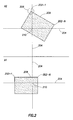
- FIG. 2 is a model of an embodiment of an object 208 detected by the system 100 using terrain features.
- the sensor element 104 of FIG. 1 captures a scan image A1 at time T1 and a scan image A2 at time T2.
- the scan images A1 and A2 are provided by way of explanation and not by way of limitation. It is to be understood that the object 208 and the scan images A1 and A2 will vary in operation depending on the area near the object 208 in which the system 100 is located. In particular, although the object 208 is shown as a rectangle in FIG.
- the object 208 is any appropriate landmark or object from which certain, uncertain, or unmatched terrain features are determined (for example, the object 208 is one of a tunnel, a building, a tower, a tree, a river, or the like).
- These certain, uncertain, or unmatched terrain features refer to any geometric terrestrial entity (for example, a particular elevational point, contour, plane, or surface) of the object 208 discovered in a set of one or more scans that have a high contrast with respect to the surrounding scans in the images A1 and A2.
- the terrain features are correlated using a determined probability distribution for each terrain feature, where the terrain features from the scan image A1 at time T1 have a substantially similar probability distribution as the same terrain features in the scan image A2 at time T2.
- the object 208 comprises a plurality of terrain features 202 1 to 202 N . Also shown in each of the scan images A1 and A2 are coordinate axes 204.
- the coordinate axes 204 are provided for purposes of explanation, but are not necessary for operation. In particular, the coordinate axes 204 demonstrate the relative position of the object 208 in each of the scan images A1 and A2.
- the sensor element 104 obtains the scan image A1 at the time T1 and the scan image A2 and the time T2. As illustrated in FIG. 2 , the object 208 is offset differently from a center 210 in the scan image A1 and in the scan image A2.
- the processing unit 106 of FIG. 1 locates the terrain features 202 1 to 202 N in each of the scan images A1 and A2. Once the terrain features 202 1 to 202 N are located, the processing unit 106 correlates the respective locations of each of the terrain features 202 in the scan image A1 with the same terrain features 202 in the scan image A2.
- the processing unit 106 correlates the location of terrain feature 202 1 in the scan image A1 with the location of terrain feature 202 1 in the scan image A2.
- Any appropriate technique will locate the terrain features 202 1 to 202 N (for example, at least one of a Harris corner detector and a Kanade-Lucas-Tomasi, or KLT, corner detector, as discussed in the '893 Application).
- the system 100 comprises at least one process for driftless SLAM (D-SLAM) navigation that filters the correlated measurements to determine the updated position and attitude estimates for the navigation platform provided in FIGS. 1 and 2 .
- D-SLAM driftless SLAM
- the processing unit 106 determines the position and attitude estimate of the object 208.
- the host platform that comprises the system 100 has banked and turned to the left as well as pitched downward.
- the movement of the host platform causes the object 208 as depicted in the scan image A2, for example, to move and rotate to the right, and to move up in the scan image A2.
- the host platform moves toward the object 208 causing the object 208 to be larger in the scan image A2. Therefore, the terrain features 202 1 to 202 N in the scan image A2 are not located near the original position (that is, the scan location) of the terrain features 202 1 to 202 N in the scan image A1.
- the processing unit 106 uses IMU data received from the IMU 102 to determine an approximate location of the terrain features 202 1 to 202 N in the scan image A2. For example, the processing unit 106 locates the terrain feature 202 1 in the scan image A1 as a starting point. The processing unit 106 propagates the location of the terrain feature 202 1 forward based on data received from the IMU 102 over the time period between time T1 and time T2. In propagating the location forward, the processing unit 106 identifies an area 206 in which the terrain feature 202 1 is located. The area 206 results from the known approximate error of measurements obtained from the IMU 102.
- the processing unit 106 evaluates the scans in the area 206 to identify the actual location of the terrain feature 202 1 in the scan image A2.
- the processing unit 106 uses known techniques, such as the KLT corner detection, to locate the terrain feature 202 1 in the area 206.
- known techniques such as the KLT corner detection
- the processing unit 106 is able to locate the terrain feature 202 1 substantially faster than in known navigation systems that search substantially larger areas.
- the processing unit 106 uses the IMU data to estimate the location of the terrain features 202 1 to 202 N , as further discussed below with respect to FIG. 3 .
- FIG. 3 is a process diagram of an embodiment of a method 300 for navigating using a navigation system to detect terrain features.
- the method 300 addresses detecting terrain features using the navigation system and host platform depicted in FIGS. 1 and 2 .
- data comprising the terrain features considered in the process of FIG. 3 includes, without limitation, digital terrain elevation data (DTED), shuttle radar topography model (SRTM) data, MICROSOFT Virtual Earth data, high-resolution terrain information (HRTI) data, or the like.
- DTED digital terrain elevation data
- SRTM shuttle radar topography model
- HRTI high-resolution terrain information
- the method 300 predicts motion of the host platform using a combination of previously-identified (that is, the "certain” terrain features discussed above) and one or more "uncertain” or “unmatched” terrain features (that is, the one or more terrain features that are currently being measured but not present or recorded in a terrain feature database represented at block 328).
- at least a first data structure of the terrain feature database of block 328 comprises the certain, uncertain, and unmatched terrain features that are being measured in near real time and at least a second data structure stores the terrain features that were known a priori .
- one or more of the terrain features detected by the method 300 provide navigational information suitable for use by the host platform (such as latitude, longitude, altitude, or the like). This navigational information is also stored in the data structures of the database at block 328.
- the method 300 identifies a first set of terrain features relative to the current location of the host platform in a first sensor scan at a first time (for example, terrain features within a sensor "field of view" for the host platform).
- the method 300 locates at least a second set of the terrain features in near real time using inertial measurement data from the first sensor scan and the first set of terrain features located in the first sensor scan for a time period between the first and second times based at least in part on a landmark prediction model (block 302).
- the landmark prediction module in block 302 comprises a 3-D terrain correlation model that locates at least the second set of the terrain features provided by the inertial measurement data from the first sensor scan.
- the prediction model of block 302 reads one or more new terrain feature measurements (for example, one or more new measurements 304) adjacent to an area surrounding the host platform at the first time scan.
- the method 300 locates at least the first set of terrain features from the second set of the terrain features in at least a second sensor scan received at the second time based at least in part on the inertial measurement data of the first time and position estimation of the host platform as discussed below.
- the method 300 correlates the first and second sets of the presently identified terrain features to determine a current position estimate of the host platform with respect to the one or more terrain features (block 306).
- the matching module at block 306 matches the currently measured terrain features to the terrain features in the database and mapping module 318.
- the matching terrain feature data is used by a correction module 320 to locate the host platform in the database reference frame to substantially remove any navigational drift that has accumulated relative to the current location of the host platform.
- the method 300 provides the navigation system 100 with corrected navigational data in the event that the navigation system 100 is not able to correlate any of the measured terrain features to the terrain features previously identified in the database and mapping module 318.
- the method 300 compares the first and second sets of terrain features to determine if at least one of the "uncertain” or “unmatched” terrain features of the second set substantially corresponds with (that is, matches) one or more of the "certain" terrain features of the first set.
- the current terrain feature measurement does not have a match (for example, is a new landmark or object) the current terrain feature measurement is routed to an unmatched index (block 308).
- the current measurement that corresponds is placed in a matched index (block 310).
- the unmatched terrain features are matched to a terrain feature database in connection with a terrain feature map block 318 as discussed in further detail below.
- a feature rejection function module 314 validates the (now-correlated) set of terrain features to reject any predictions of the matching terrain features that exceed a prescribed prediction threshold.
- the feature rejection function module 314 uses a RANdom SAmple Consensus (RANSAC) program to reject bad feature matches.
- RANSAC RANdom SAmple Consensus
- the RANSAC program employed in the process of FIG. 3 uses an iterative technique to estimate parameters of a mathematical model from a set of observed data.
- the RANSAC program divides the data into (1) "inliers" (data points that can be explained by some set of model parameters), and (2) "outliers" (data points that do not fit the model).
- the outliers can arise from noise or erroneous prediction measurements of the terrain features.
- the method 300 uses the near best terrain feature "candidates" between the predicted set of matching terrain features and the correlated set of matching terrain features to correct the predicted state of the measurement process depicted in FIG. 3 (block 316, and the correction module 320).
- the correction module 320 comprises a Kalman filter, a D-SLAM filter, or the like, for correcting the predicted terrain feature measurements and substantially reducing any navigational drift present in the navigation system.
- the method 300 determines a probability distribution of each of the located terrain features from the second sensor scan. In determining the probability distribution, the method 300 ensures that each of the located terrain features of the second sensor scan have a substantially similar feature point contrast level as the current prediction of a terrain feature Y Lmk being located using a landmark sub-map from a database landmark selector module (block 312). In one embodiment, the landmark sub-map data is continually re-sampled in near real time as depicted in the process of FIG. 3 to further verify the probability distribution of the current terrain feature prediction.
- the landmark sub-map data from the database landmark selector module at block 312 further uses properties of one or more navigational sensors (such as the sensor field of view, a sensor focal length, and the like) used in the first and second sensor scans in determining the probability distribution of the located terrain features.
- one or more navigational sensors such as the sensor field of view, a sensor focal length, and the like
- the method 300 records the newly-identified, previously unmatched terrain features in a similar mapping structure as the first set of located terrain features. For example, after the correction module of block 320 corrects the predicted states of the (now-certain) terrain features with current measurements, a terrain feature map at block 318 is updated with the corrected position of each of the identified terrain features. Once all of the terrain features in the terrain feature map at block 318 are determined to be within a prescribed accuracy, the navigational data associated with the terrain features are translated using an inverse translator function (block 326). The translated navigation data are updated in the terrain feature database at block 328. In one embodiment, the translations performed by the inverse translator function at block 326 convert the (previously) uncertain and unmatched terrain features observed by the sensor element 104 of FIG. 1 into the same format of the certain terrain features in the terrain feature database at block 328.
- the database and mapping module 318 uses the corrected state of the system to record the (previously) uncertain and unmatched newly terrain features into the map as new (additional) terrain features based, at least in part, on the position estimate of the host platform.
- the database landmark selector module at block 312 reads the terrain feature database at block 328 via a translator function at block 324 and the terrain feature map at block 318 to select at least a portion of the unmatched terrain features that will be matched against a new sensor measurement.
- the selected unmatched terrain features are also the filtered landmark states of the correction module of block 320 that are initialized for the next set of measurements at block 322.
- the database and mapping module 318 provides the correlated set of terrain features as the corrected state of the system to the output terminal 110 of the navigation system at block 322, and returns to perform another measurement interval at block 302.
- FIG. 4 is a flow diagram of an embodiment of a method of navigating from terrain features.
- the method 400 addresses terrain feature prediction and determination based on an existing terrain mapping database of "certain" terrain features and, in one embodiment, the method 400 records additional "uncertain” and "unmatched” terrain features to be included in the existing terrain mapping database.
- the method 400 identifies a set of terrain features of an area substantially surrounding a navigation platform, the navigation platform having a system for simultaneous localization and mapping (block 402).
- the method 400 identifies a current position estimate from a terrain correlation prediction model (similar to the prediction model discussed above with respect to FIG. 3 ) that matches with one or more previously-identified terrain feature measurements from at least one sensor element of the navigation system.
- the method 400 For each terrain feature identified, the method 400 records current navigational data as the navigation platform traverses the area (block 404). In one implementation, the method 400 records the navigational data of the area encompassing the identified terrain features to determine, in near real time, a probability distribution of one or more of the identified terrain features measured with at least one sensor element of the navigation system.
- the method 400 correlates the current navigational data of each of the identified terrain features with prior navigational data of previously-determined terrain features from an existing terrain mapping database accessed by the navigation platform (block 406). When the correlated navigational data exceeds a prescribed correlation threshold (block 408), the method 400 repeats at block 406 until the recorded navigational data are within the prescribed correlation threshold. In one implementation, the method 400 compares the current navigational data with the prior navigational data to determine if at least one of the currently identified terrain features matches one or more of the previously-determined terrain features in the existing terrain mapping database. As discussed above with respect to FIG. 3 , the method 400 validates the correlated data to remove any sample comparisons that exceed the prescribed correlation threshold.
- the method 400 provides a current position estimate for the navigation platform (block 410).
- the method 400 uses the current position estimate of the navigation platform to predict a location of each of the identified local terrain features.
- the method 400 further incorporates the predicted terrain feature locations that are not found in the prior navigational data of the previously-determined terrain features as additional terrain features to be navigated by the navigation platform and recorded in the existing terrain mapping database.
- the additional terrain features are translated into a suitable representation for the existing terrain mapping database of the previously-determined terrain features.
- the methods and techniques described herein may be implemented in a combination of digital electronic circuitry and software (or firmware) residing in a programmable processor.
- An apparatus embodying these techniques may include appropriate input and output devices, a programmable processor, and a storage medium tangibly embodying program instructions for execution by the programmable processor.
- a process embodying these techniques may be performed by a programmable processor executing a program of instructions that operates on input data and generates appropriate output data.
- the techniques may be implemented in one or more programs that are executable on a programmable system including at least one programmable processor coupled to receive data and instructions from (and to transmit data and instructions to) a data storage system, at least one input device, and at least one output device.
- a processor will receive instructions and data from at least one of a read only memory (ROM) and a random access memory (RAM).
- storage media suitable for tangibly embodying computer program instructions and data include all forms of non-volatile memory, and include by way of example, semiconductor memory devices; magnetic disks such as internal hard disks and removable disks; magneto-optical discs; optical discs, and other computer-readable media. Any of the foregoing may be supplemented by, or incorporated in, specially-designed application-specific integrated circuits (ASICs).
- ASICs application-specific integrated circuits
- a computer When information is transferred or provided over a network or another communications connection (either hardwired, wireless, or a combination of hardwired or wireless) to a computer, a computer properly views the connection as a computer-readable medium. Thus, any such connection is properly termed a computer-readable medium. Combinations of the above are also included within the scope of computer-readable media.
Landscapes
- Engineering & Computer Science (AREA)
- Radar, Positioning & Navigation (AREA)
- Remote Sensing (AREA)
- Physics & Mathematics (AREA)
- Automation & Control Theory (AREA)
- General Physics & Mathematics (AREA)
- Electromagnetism (AREA)
- Navigation (AREA)
- Instructional Devices (AREA)
Abstract
Description
- This application is related to commonly assigned
U.S. Patent Application Serial No. 11/673,893, filed on Feb. 12, 2007 U.S. Patent Application Serial No. 11/692,651, filed on Mar. 28, 2007 - Simultaneous localization and mapping (SLAM) is a navigation process used by numerous autonomous vehicle platforms for navigating to a destination while simultaneously generating a map of surrounding terrain. The SLAM process is indifferent with respect to various sensor technologies and typically comprises a Kalman filter to generate a map which contains "features," or processed sensor returns of the surrounding terrain.
- Typically, any navigation provided by the SLAM process is not based on any prior study or examination of the terrain. As a result, any mapping and localization errors during the navigation process contribute to a growing uncertainty in position estimates of the vehicle, commonly referred to as navigation drift. Since this uncertainty exists in current implementations of SLAM, SLAM is not considered a reliable stand-alone navigational aid. Thus, there is a need in the art for improvements in navigation using terrain features.
- The following specification provides at least one method and system of navigation using terrain features. Particularly, in one embodiment, a method of navigating from terrain features is provided. The method identifies a set of terrain features of an area substantially surrounding a navigation platform having a system for simultaneous localization and mapping. For each terrain feature identified, the method records current navigational data as the navigation platform traverses the area, and correlates the current navigational data of each of the identified local terrain features with prior navigational data of previously-determined terrain features from an existing terrain mapping database accessed by the navigation platform to within a prescribed correlation threshold. From at least the correlated navigational data of the identified terrain features, the method provides a current position estimate for the navigation platform.
- These and other features, aspects, and advantages are better understood with regard to the following description, appended claims, and accompanying drawings where:
-
FIG. 1 is a block diagram of an embodiment of a navigation system; -
FIG. 2 is a model of an embodiment of a object detected by a navigation system using terrain features; -
FIG. 3 is a process diagram of an embodiment of a method for navigating using a navigation system to detect terrain features; and -
FIG. 4 is a flow diagram of an embodiment of a method of navigating from terrain features. - The various described features are drawn to emphasize features relevant to the embodiments disclosed. Like reference characters denote like elements throughout the figures and text of the specification.
- The following detailed description relates to at least one embodiment of navigation using terrain features from an existing terrain map, and combining existing terrain features in an a priori database with additional terrain features determined in near real time. For example, at least one navigational sensor element, in communication with an inertial measurement unit (IMU), provides terrain feature correlation from the existing map of terrain features and the near real time determination of the same and any additional features, including the presence of any new objects within the area presently under navigation. In one embodiment, the map comprises a digital terrain elevation data (DTED) database having the terrain features of previously-identified landmarks. The near real time correlation that identifies any of the additional features (objects) existing in the area identified in the DTED database is accomplished using either vision- or laser-based sensor elements of a system having simultaneous localization and mapping (SLAM).
- For purposes of this description, the terrain features of the previously-identified landmarks are referred to as "certain" terrain features recorded in the a priori database, and the newly-identified object features are referred to as "uncertain" terrain features. In addition, the terrain feature correlation methods discussed herein comprise at least one method of navigation using a SLAM framework that filters the correlated certain and uncertain terrain feature measurements with a current tracking of "unmatched" landmark or object features that have not been identified as either certain or uncertain terrain features. Moreover, the navigation by terrain features discussed herein provides substantially driftless navigation based on any updates in position and attitude estimates from a host platform having the navigation system, as discussed in further detail below.
-
FIG. 1 is a block diagram of an embodiment of anavigation system 100. Thesystem 100 comprises at least aprocessing unit 106, amemory unit 112, anIMU 102, and asensor element 104. Thesensor element 104 and theIMU 102 are each coupled to theprocessing unit 106 and provide input data to theprocessing unit 106 for estimating motion (for example, position, velocity, or any suitable combination thereof). Thememory unit 112 includes adatabase 114 in operative communication with theprocessing unit 106. Thesystem 100 further comprises an optional navigation-aiding sensor 108 and anoptional output terminal 110, each of which are in operative communication with theprocessing unit 106. In the example embodiment ofFIG. 1 , thesystem 100 resides on or is associated with a particular host platform including, without limitation, an aircraft, an automobile, a person, or any other navigation platform that requires near real-time, multi-dimensional SLAM navigation information. - In one implementation, the optional navigation-
aiding sensor 108 is one of a global positioning system (GPS) sensor, a magnetometer, a barometric altimeter, a Doppler radar, an odometer, and any other suitable navigation-aiding sensor or sensor element. For example, thesystem 100 is considered an inertial navigation system when the primary navigation function is based on processing the IMU sensor data. Similarly, thesystem 100 is considered a dead-reckoning navigation system when the primary navigation function is based on a heading measurement from the optional magnetometer or other heading measurement method, such as a heading gyro, and a measurement of distance traveled from the optional odometer, Doppler radar, or other distance-traveled measurement method. Inertial navigation, dead reckoning, or a hybrid of inertial and dead reckoning are further possible implementations. - The IMU 102 measures motion in at least three degrees of freedom. In particular, the
IMU 102 includes sensors to measure acceleration along three orthogonal coordinate axes and angular acceleration about each of the three orthogonal coordinate axes. For example, theIMU 102 comprises, but is not limited to, up to three linear accelerometers configured to obtain acceleration along the three coordinate axes, and up to three gyroscopes to measure angular acceleration about the same three coordinate axes. In other words, the gyroscope measurements are used to estimate attitude or orientation of the host platform, and the accelerometer measurements are used to estimate position and velocity, including the effects of gravity. As described in further detail below, theprocessing unit 106 determines an absolute orientation (position) of thesystem 100 based on the motion measured by theIMU 102. - The
sensor element 104 transmits a signal (for example, a laser) out to at least one terrain feature, as further discussed below with respect toFIG. 2 . The transmitted signal interacts with and is modified by the at least one terrain feature. For example, at least some of the transmitted signal is reflected (scattered) back to thesensor element 104 for analysis by theprocessing unit 106. The change in the properties of the reflected signal enables one or more characteristics of the at least one terrain feature to be determined (for example, light reflected from a corner or elevation point of the at least one terrain feature). - In one implementation, the
sensor element 104 is at least one of a vision sensor, range finder, millimeter wave radar, or ladar (laser detection and ranging radar). It is understood that thesensor element 104 is suitable for implementation in any appropriate manner for emitting or receiving a signal with any other current and future multi-dimensional sensor technology. For example, thesensor element 104 embodied as the range finder measures the distance from the range finder in the host platform to the terrain feature by emitting light in a single (for example, a horizontal) direction. The time for the light to travel out to the terrain feature and back to the range finder is used to determine the range to the terrain feature. Similarly, thesensor element 104 embodied as the ladar measures the distance from the ladar to the terrain feature by emitting light in multiple directions at substantially the same time. - In a similar implementation, the
sensor element 104 is used concurrently with the navigation-aiding sensor 108. For example, when the navigation-aiding sensor 108 is embodied as the GPS sensor, thesensor element 104 can be used whenever a GPS satellite signal is unavailable or concurrently with the GPS sensor regardless of availability of a GPS satellite signal. Alternatively, the navigation-aiding sensor 108 is omitted in some embodiments. In such embodiments, data from the IMU 102 is only updated with measurements from thesensor element 104. - The
processing unit 106 comprises a plurality of program instructions for carrying out the various process tasks, calculations, and generation of signals and other data used in the operation of thesystem 100, such as to correlate the location of the terrain features of thedatabase 114 with current navigation measurements and to determine the velocity and position of the device in whichsystem 100 is located. For example, thesystem 100 uses thesensor element 104 to correct and update the terrain features stored in thedatabase 114 based on IMU data from the IMU 102. In some embodiments, the calculated position based on the IMU data from theIMU 102 is combined with the calculated position from thesensor element 104. In other embodiments, the calculated position from thesensor element 104 is used in place of the calculated position based on the IMU data from theIMU 102. In such embodiments, theprocessing unit 106 estimates the location of the terrain features in a plurality of scans captured by thesensor element 104. It is understood that the plurality of scans discussed herein refer to at least one of a plurality of line, range, or flash scans. - In operation, the
sensor element 104 measures, within a first frame, terrain features of an area adjacent to thesystem 100 at a first time and within at least one second frame at a second time. TheIMU 102 obtains navigational data at the first and second times. In one embodiment, theprocessing unit 106 predicts a current state and position of thesystem 100 within the first and second times using theIMU 102 and thesensor element 104. Theprocessing unit 106 correlates the actual scan location of one or more of the terrain features of the area adjacent to thesystem 100 from the first and second times, as discussed in further detail below. In the example embodiment ofFIG. 1 , theprocessing unit 106 uses at least one form of a probability distribution, or probability distribution function (PDF), to perform terrain feature correlation in up to three dimensions based on the measurements obtained from thesensor element 104. - In at least one similar embodiment, the
memory unit 112 stores terrain feature data in the database 144 based on the terrain features obtained at the first and second times by theprocessing unit 106. Thememory unit 112 records navigational properties of the terrain features in at least one of the second frames based at least in part on the navigational data from the first and second times in thedatabase 114 as discussed below. - In one implementation, the
processing unit 106 combines the estimated position from theIMU 102 and thesensor element 104 to obtain a more accurate position estimate. For example, theprocessing unit 106 identifies a first scan location of the one or more terrain features in each first frame, selects a second scan location in the at least one second range based on the motion data from the inertial measurement unit, and evaluates frame scans near the second scan location to identify the actual scan location of the one or more terrain features in the at least one second frame. Theprocessing unit 106 then correlates each of the terrain features by comparing a position estimate of each of the terrain features in the two first frames with the position estimate of each of the terrain features in the at least one second frame. Moreover, theprocessing unit 106 estimates position based on the navigational data received from at least one of theGPS sensor 108, theIMU 102, and thesensor element 104. - In one embodiment, the
output terminal 110 displays the terrain features of previously-identified landmarks and any additional objects present in the area adjacent to thesystem 100, and displays the current state and position of thesystem 100 based on signals received from theprocessing unit 106. In some embodiments, the more accurate position estimate is (optionally) obtained from theoutput terminal 110. For example, an automobile using the system 100 (as the host platform) will use navigation data provided by theoutput terminal element 110 to display to a driver of the automobile where the automobile is located on a map. In other embodiments, theprocessing unit 106 uses the more accurate estimate to determine the necessary actions to take in order to reach a programmed destination, as described in the '893 Application. - To achieve the terrain feature navigation discussed herein, the
processing unit 106 correlates the location of a first set of terrain features from each of the scan images processed at a first moment in time with the location of at least a second set of terrain features from each of the scan images processed at a second moment in time. In the example embodiment ofFIG. 1 , theprocessing unit 106 predicts the location of each set of the terrain features in the scans from thesensor element 104 at the second moment in time based on data received from theIMU 102 and the location of the first set of terrain features in scans obtained at the first moment in time. The prediction of the location of the second set of terrain features in the second image is described in more detail below with respect toFIG. 2 . In one embodiment, theprocessing unit 106 filters the correlated terrain features using three-dimensional (3-D) feature probability distribution measurements provided from thesensor element 104. For example, theprocessing unit 106 determines the change in position of the host platform based on the probability distribution between the first and second sets of terrain features, and updates the terrain feature data stored in thedatabase 114 based on the filtered set of terrain feature measurements. -
FIG. 2 is a model of an embodiment of anobject 208 detected by thesystem 100 using terrain features. For example, as shown inFIG. 2 , thesensor element 104 ofFIG. 1 captures a scan image A1 at time T1 and a scan image A2 at time T2. The scan images A1 and A2 are provided by way of explanation and not by way of limitation. It is to be understood that theobject 208 and the scan images A1 and A2 will vary in operation depending on the area near theobject 208 in which thesystem 100 is located. In particular, although theobject 208 is shown as a rectangle inFIG. 2 , it is to be understood that in other embodiments theobject 208 is any appropriate landmark or object from which certain, uncertain, or unmatched terrain features are determined (for example, theobject 208 is one of a tunnel, a building, a tower, a tree, a river, or the like). These certain, uncertain, or unmatched terrain features, as described herein with respect toFIGS. 2 and3 , refer to any geometric terrestrial entity (for example, a particular elevational point, contour, plane, or surface) of theobject 208 discovered in a set of one or more scans that have a high contrast with respect to the surrounding scans in the images A1 and A2. For example, the terrain features are correlated using a determined probability distribution for each terrain feature, where the terrain features from the scan image A1 at time T1 have a substantially similar probability distribution as the same terrain features in the scan image A2 at time T2. - In the example embodiment of
FIG. 2 , theobject 208 comprises a plurality of terrain features 2021 to 202N. Also shown in each of the scan images A1 and A2 are coordinateaxes 204. The coordinateaxes 204 are provided for purposes of explanation, but are not necessary for operation. In particular, the coordinateaxes 204 demonstrate the relative position of theobject 208 in each of the scan images A1 and A2. - In operation, the
sensor element 104 obtains the scan image A1 at the time T1 and the scan image A2 and the time T2. As illustrated inFIG. 2 , theobject 208 is offset differently from acenter 210 in the scan image A1 and in the scan image A2. In one implementation, once the scan images A1 and A2 are captured, theprocessing unit 106 ofFIG. 1 locates the terrain features 2021 to 202N in each of the scan images A1 and A2. Once the terrain features 2021 to 202N are located, theprocessing unit 106 correlates the respective locations of each of the terrain features 202 in the scan image A1 with the same terrain features 202 in the scan image A2. For example, theprocessing unit 106 correlates the location ofterrain feature 2021 in the scan image A1 with the location ofterrain feature 2021 in the scan image A2. Any appropriate technique will locate the terrain features 2021 to 202N (for example, at least one of a Harris corner detector and a Kanade-Lucas-Tomasi, or KLT, corner detector, as discussed in the '893 Application). In the navigation methods discussed above and in further detail below with respect toFIG. 3 , thesystem 100 comprises at least one process for driftless SLAM (D-SLAM) navigation that filters the correlated measurements to determine the updated position and attitude estimates for the navigation platform provided inFIGS. 1 and2 . - For example, once each of the terrain features 202 are correlated, the
processing unit 106 determines the position and attitude estimate of theobject 208. For example, in this embodiment, the host platform that comprises thesystem 100 has banked and turned to the left as well as pitched downward. The movement of the host platform causes theobject 208 as depicted in the scan image A2, for example, to move and rotate to the right, and to move up in the scan image A2. In the example embodiment ofFIG. 2 , the host platform moves toward theobject 208 causing theobject 208 to be larger in the scan image A2. Therefore, the terrain features 2021 to 202N in the scan image A2 are not located near the original position (that is, the scan location) of the terrain features 2021 to 202N in the scan image A1. - The
processing unit 106 uses IMU data received from theIMU 102 to determine an approximate location of the terrain features 2021 to 202N in the scan image A2. For example, theprocessing unit 106 locates theterrain feature 2021 in the scan image A1 as a starting point. Theprocessing unit 106 propagates the location of theterrain feature 2021 forward based on data received from theIMU 102 over the time period between time T1 and time T2. In propagating the location forward, theprocessing unit 106 identifies anarea 206 in which theterrain feature 2021 is located. Thearea 206 results from the known approximate error of measurements obtained from theIMU 102. For example, if theIMU 102 measures a lateral movement of two meters to the right over a time period of one second but has a known error of about 0.1 meters/second, the actual location ofterrain feature 2021 is between about 1.9-2.1 meters to the right of its location at time T1. Theprocessing unit 106 evaluates the scans in thearea 206 to identify the actual location of theterrain feature 2021 in the scan image A2. - In the example embodiment of
FIG. 2 , theprocessing unit 106 uses known techniques, such as the KLT corner detection, to locate theterrain feature 2021 in thearea 206. By focusing on thearea 206 of the scan image A2 rather than the entire scan image, theprocessing unit 106 is able to locate theterrain feature 2021 substantially faster than in known navigation systems that search substantially larger areas. Theprocessing unit 106 uses the IMU data to estimate the location of the terrain features 2021 to 202N, as further discussed below with respect toFIG. 3 . -
FIG. 3 is a process diagram of an embodiment of amethod 300 for navigating using a navigation system to detect terrain features. In one embodiment, themethod 300 addresses detecting terrain features using the navigation system and host platform depicted inFIGS. 1 and2 . For example, in at least one implementation, data comprising the terrain features considered in the process ofFIG. 3 includes, without limitation, digital terrain elevation data (DTED), shuttle radar topography model (SRTM) data, MICROSOFT Virtual Earth data, high-resolution terrain information (HRTI) data, or the like. - In one embodiment, the
method 300 predicts motion of the host platform using a combination of previously-identified (that is, the "certain" terrain features discussed above) and one or more "uncertain" or "unmatched" terrain features (that is, the one or more terrain features that are currently being measured but not present or recorded in a terrain feature database represented at block 328). Moreover, at least a first data structure of the terrain feature database ofblock 328 comprises the certain, uncertain, and unmatched terrain features that are being measured in near real time and at least a second data structure stores the terrain features that were known a priori. In one implementation, one or more of the terrain features detected by themethod 300 provide navigational information suitable for use by the host platform (such as latitude, longitude, altitude, or the like). This navigational information is also stored in the data structures of the database atblock 328. - To further aid in the description of the
method 300, the following description of nomenclature appearing inFIG. 3 is provided below: - State of navigator, XN - position, velocity and attitude in three-dimensional (3-D) space
- States of landmark, XLmk , YLmk - position in 3-D space, where YLmk represents at least one predicted terrain feature based on landmark identification
- Covariance of navigator, PN - uncertainty of state of navigator
- Covariance of landmark, PLmk - uncertainty of state of landmark
- Covariance of measurement, R - measurement noise
- Covariance of model, Q - system model (process) noise
- Time interval, k - completion time for one measurement interval
- In operation, the
method 300 identifies a first set of terrain features relative to the current location of the host platform in a first sensor scan at a first time (for example, terrain features within a sensor "field of view" for the host platform). In the example embodiment ofFIG. 3 , the states XN, XLmk and the covariance values Q, PN and PLmk are initially set at time k = 0. In one particular embodiment, the navigator and landmark states and covariance values are corrected in at least one measurement interval (for example, when time k =1) as discussed in further detail below. - The
method 300 locates at least a second set of the terrain features in near real time using inertial measurement data from the first sensor scan and the first set of terrain features located in the first sensor scan for a time period between the first and second times based at least in part on a landmark prediction model (block 302). For example, the landmark prediction module inblock 302 comprises a 3-D terrain correlation model that locates at least the second set of the terrain features provided by the inertial measurement data from the first sensor scan. Moreover, in further determining the current location of the host platform, the prediction model ofblock 302 reads one or more new terrain feature measurements (for example, one or more new measurements 304) adjacent to an area surrounding the host platform at the first time scan. Based on the current states of the system from the prediction model ofblock 302, themethod 300 locates at least the first set of terrain features from the second set of the terrain features in at least a second sensor scan received at the second time based at least in part on the inertial measurement data of the first time and position estimation of the host platform as discussed below. - The
method 300 correlates the first and second sets of the presently identified terrain features to determine a current position estimate of the host platform with respect to the one or more terrain features (block 306). In one implementation, the matching module atblock 306 matches the currently measured terrain features to the terrain features in the database andmapping module 318. With reference to the frame model discussed above with respect toFIG. 2 , when the currently measured terrain features match a known location in the database frame of reference of the database andmapping module 318, the matching terrain feature data is used by acorrection module 320 to locate the host platform in the database reference frame to substantially remove any navigational drift that has accumulated relative to the current location of the host platform. In one implementation, themethod 300 provides thenavigation system 100 with corrected navigational data in the event that thenavigation system 100 is not able to correlate any of the measured terrain features to the terrain features previously identified in the database andmapping module 318. - As shown in
FIG. 3 , themethod 300 compares the first and second sets of terrain features to determine if at least one of the "uncertain" or "unmatched" terrain features of the second set substantially corresponds with (that is, matches) one or more of the "certain" terrain features of the first set. When the current terrain feature measurement does not have a match (for example, is a new landmark or object) the current terrain feature measurement is routed to an unmatched index (block 308). The current measurement that corresponds is placed in a matched index (block 310). The unmatched terrain features are matched to a terrain feature database in connection with a terrain feature map block 318 as discussed in further detail below. - In one implementation, a feature
rejection function module 314 validates the (now-correlated) set of terrain features to reject any predictions of the matching terrain features that exceed a prescribed prediction threshold. In one implementation, the featurerejection function module 314 uses a RANdom SAmple Consensus (RANSAC) program to reject bad feature matches. Further details regarding RANSAC are found in an article by M. A. Fischler, R. C. Bolles, "Random Sample Consensus: A Paradigm for Model Fitting with Applications to Image Analysis and Automated Cartography," Comm. of the ACM 24: 381-395 (June 1981), which is incorporated herein by reference. - The RANSAC program employed in the process of
FIG. 3 uses an iterative technique to estimate parameters of a mathematical model from a set of observed data. The RANSAC program divides the data into (1) "inliers" (data points that can be explained by some set of model parameters), and (2) "outliers" (data points that do not fit the model). In the example embodiment of the process ofFIG. 3 , the outliers can arise from noise or erroneous prediction measurements of the terrain features. For example, themethod 300 uses the near best terrain feature "candidates" between the predicted set of matching terrain features and the correlated set of matching terrain features to correct the predicted state of the measurement process depicted inFIG. 3 (block 316, and the correction module 320). In one embodiment, thecorrection module 320 comprises a Kalman filter, a D-SLAM filter, or the like, for correcting the predicted terrain feature measurements and substantially reducing any navigational drift present in the navigation system. - Referring back to the location of the (presently-identified) terrain features, in one embodiment, the
method 300 determines a probability distribution of each of the located terrain features from the second sensor scan. In determining the probability distribution, themethod 300 ensures that each of the located terrain features of the second sensor scan have a substantially similar feature point contrast level as the current prediction of a terrain feature YLmk being located using a landmark sub-map from a database landmark selector module (block 312). In one embodiment, the landmark sub-map data is continually re-sampled in near real time as depicted in the process ofFIG. 3 to further verify the probability distribution of the current terrain feature prediction. The landmark sub-map data from the database landmark selector module atblock 312 further uses properties of one or more navigational sensors (such as the sensor field of view, a sensor focal length, and the like) used in the first and second sensor scans in determining the probability distribution of the located terrain features. - Moreover, in one implementation, the
method 300 records the newly-identified, previously unmatched terrain features in a similar mapping structure as the first set of located terrain features. For example, after the correction module ofblock 320 corrects the predicted states of the (now-certain) terrain features with current measurements, a terrain feature map atblock 318 is updated with the corrected position of each of the identified terrain features. Once all of the terrain features in the terrain feature map atblock 318 are determined to be within a prescribed accuracy, the navigational data associated with the terrain features are translated using an inverse translator function (block 326). The translated navigation data are updated in the terrain feature database atblock 328. In one embodiment, the translations performed by the inverse translator function atblock 326 convert the (previously) uncertain and unmatched terrain features observed by thesensor element 104 ofFIG. 1 into the same format of the certain terrain features in the terrain feature database atblock 328. - The database and
mapping module 318 uses the corrected state of the system to record the (previously) uncertain and unmatched newly terrain features into the map as new (additional) terrain features based, at least in part, on the position estimate of the host platform. In one implementation, the database landmark selector module atblock 312 reads the terrain feature database atblock 328 via a translator function atblock 324 and the terrain feature map atblock 318 to select at least a portion of the unmatched terrain features that will be matched against a new sensor measurement. Moreover, the selected unmatched terrain features are also the filtered landmark states of the correction module ofblock 320 that are initialized for the next set of measurements atblock 322. In addition, the database andmapping module 318 provides the correlated set of terrain features as the corrected state of the system to theoutput terminal 110 of the navigation system atblock 322, and returns to perform another measurement interval atblock 302. -
FIG. 4 is a flow diagram of an embodiment of a method of navigating from terrain features. Themethod 400 addresses terrain feature prediction and determination based on an existing terrain mapping database of "certain" terrain features and, in one embodiment, themethod 400 records additional "uncertain" and "unmatched" terrain features to be included in the existing terrain mapping database. For example, themethod 400 identifies a set of terrain features of an area substantially surrounding a navigation platform, the navigation platform having a system for simultaneous localization and mapping (block 402). In one implementation, themethod 400 identifies a current position estimate from a terrain correlation prediction model (similar to the prediction model discussed above with respect toFIG. 3 ) that matches with one or more previously-identified terrain feature measurements from at least one sensor element of the navigation system. For each terrain feature identified, themethod 400 records current navigational data as the navigation platform traverses the area (block 404). In one implementation, themethod 400 records the navigational data of the area encompassing the identified terrain features to determine, in near real time, a probability distribution of one or more of the identified terrain features measured with at least one sensor element of the navigation system. - The
method 400 correlates the current navigational data of each of the identified terrain features with prior navigational data of previously-determined terrain features from an existing terrain mapping database accessed by the navigation platform (block 406). When the correlated navigational data exceeds a prescribed correlation threshold (block 408), themethod 400 repeats atblock 406 until the recorded navigational data are within the prescribed correlation threshold. In one implementation, themethod 400 compares the current navigational data with the prior navigational data to determine if at least one of the currently identified terrain features matches one or more of the previously-determined terrain features in the existing terrain mapping database. As discussed above with respect toFIG. 3 , themethod 400 validates the correlated data to remove any sample comparisons that exceed the prescribed correlation threshold. From at least the correlated navigational data of the identified terrain features, themethod 400 provides a current position estimate for the navigation platform (block 410). In one embodiment, themethod 400 uses the current position estimate of the navigation platform to predict a location of each of the identified local terrain features. Themethod 400 further incorporates the predicted terrain feature locations that are not found in the prior navigational data of the previously-determined terrain features as additional terrain features to be navigated by the navigation platform and recorded in the existing terrain mapping database. As discussed above with respect toFIG. 3 , in one implementation, the additional terrain features are translated into a suitable representation for the existing terrain mapping database of the previously-determined terrain features. - The methods and techniques described herein may be implemented in a combination of digital electronic circuitry and software (or firmware) residing in a programmable processor. An apparatus embodying these techniques may include appropriate input and output devices, a programmable processor, and a storage medium tangibly embodying program instructions for execution by the programmable processor. A process embodying these techniques may be performed by a programmable processor executing a program of instructions that operates on input data and generates appropriate output data. The techniques may be implemented in one or more programs that are executable on a programmable system including at least one programmable processor coupled to receive data and instructions from (and to transmit data and instructions to) a data storage system, at least one input device, and at least one output device. Generally, a processor will receive instructions and data from at least one of a read only memory (ROM) and a random access memory (RAM). In addition, storage media suitable for tangibly embodying computer program instructions and data include all forms of non-volatile memory, and include by way of example, semiconductor memory devices; magnetic disks such as internal hard disks and removable disks; magneto-optical discs; optical discs, and other computer-readable media. Any of the foregoing may be supplemented by, or incorporated in, specially-designed application-specific integrated circuits (ASICs).
- When information is transferred or provided over a network or another communications connection (either hardwired, wireless, or a combination of hardwired or wireless) to a computer, a computer properly views the connection as a computer-readable medium. Thus, any such connection is properly termed a computer-readable medium. Combinations of the above are also included within the scope of computer-readable media.
- This description has been presented for purposes of illustration, and is not intended to be exhaustive or limited to the embodiments disclosed. Variations and modifications may occur, which fall within the scope of the following claims.
Claims (7)
- A navigation system (100), comprising:a sensor element (104) operable to measure, within a first frame, terrain features of an area adjacent to the navigation system at a first time and within at least one second frame at a second time;an inertial measurement unit (IMU) (102) operable to obtain navigational data at the first and second times; anda processing unit (106) coupled to the IMU and the sensor element, the processing unit configured to
based at least in part on a terrain correlation prediction model (300), predict a current state and position of a host platform having the navigation system within the first and second time intervals; and
determine an actual scan location of one or more of the terrain features of the area adjacent to the navigation system using a three-dimensional probability distribution function formed by filtering terrain feature measurements provided from the sensor element at the first and second times. - The system of claim 1 and further comprising an output terminal (110) coupled to the processing unit, the output terminal configured to
display the terrain features of previously-identified landmarks and any additional unmatched and uncertain objects (e.g., 208) present in the area adjacent to the navigation system, and
display the current state and position of the navigation system based on signals received from the processing unit. - The system of claim 1 and further comprising a navigation-aiding sensor (108) coupled to the processing unit, wherein the navigation-aiding sensor is one of a global positioning system (GPS) sensor, a magnetometer, a barometric altimeter, a Doppler radar, or an odometer, and wherein the processing unit is configured to estimate position based on the navigational data received from at least one of the navigation-aiding sensor, the IMU, and the sensor element.
- The system of claim 1 and further comprising a memory unit (112) in operative communication with the processing unit, the memory unit configured to:store a database (328) of terrain data for simultaneous localization and mapping based on the navigational data obtained during at least one of the first and second times by the processing unit; andrecord navigational properties of the sensor element to determine the probability distribution of the terrain features in the at least one second frame based on the navigational data obtained at the first and second times.
- The system of claim 1, wherein the processing unit is operable to:identify a first scan location (A1) of the terrain features in each first frame;select a second scan location (A2) in the at least one second frame based on the navigational data from the IMU; andevaluate frame scans near the second scan location to identify the actual scan location of the one or more terrain features in the at least one second frame.
- The system of claim 5, wherein the processing unit is further configured to:correlate each of the terrain features by comparing a position estimate of each of the terrain features in the first frame with a position estimate of each of the terrain features in the at least one second frame using the terrain correlation prediction model (306); andfilter the correlated terrain features to determine the change in position of the host platform based on the probability distribution between the first and second sets of terrain features (314).
- The system of claim 1, wherein the sensor element is at least one of a range finder, a ladar, a millimeter wave radar, or a vision sensor.
Applications Claiming Priority (1)
| Application Number | Priority Date | Filing Date | Title |
|---|---|---|---|
| US13590008A | 2008-06-09 | 2008-06-09 |
Publications (3)
| Publication Number | Publication Date |
|---|---|
| EP2133662A2 true EP2133662A2 (en) | 2009-12-16 |
| EP2133662A3 EP2133662A3 (en) | 2010-07-14 |
| EP2133662B1 EP2133662B1 (en) | 2012-02-01 |
Family
ID=41074039
Family Applications (1)
| Application Number | Title | Priority Date | Filing Date |
|---|---|---|---|
| EP09162088A Not-in-force EP2133662B1 (en) | 2008-06-09 | 2009-06-05 | Methods and system of navigation using terrain features |
Country Status (3)
| Country | Link |
|---|---|
| EP (1) | EP2133662B1 (en) |
| JP (1) | JP2009294214A (en) |
| AT (1) | ATE544048T1 (en) |
Cited By (24)
| Publication number | Priority date | Publication date | Assignee | Title |
|---|---|---|---|---|
| WO2010120402A1 (en) * | 2009-04-13 | 2010-10-21 | Deka Products Limited Partnership | System and apparatus for orientation control |
| US8074559B2 (en) | 2007-02-06 | 2011-12-13 | Deka Products Limited Partnership | Dynamic support apparatus and system |
| DE102010033372A1 (en) * | 2010-08-04 | 2012-02-09 | Deutsches Zentrum für Luft- und Raumfahrt e.V. | Method for determining position of rail vehicle, involves detecting surroundings of rail vehicle by a sensor, and creating model of environment of rail vehicle |
| US8449624B2 (en) | 2007-02-06 | 2013-05-28 | Deka Products Limited Partnership | Arm prosthetic device |
| US8821587B2 (en) | 2007-02-06 | 2014-09-02 | Deka Products Limited Partnership | Apparatus for control of a prosthetic |
| US8864845B2 (en) | 2007-02-06 | 2014-10-21 | DEKA Limited Partnership | System for control of a prosthetic device |
| US8870970B2 (en) | 2007-02-06 | 2014-10-28 | Deka Products Limited Partnership | Dynamic support apparatus |
| WO2015022591A1 (en) * | 2013-08-14 | 2015-02-19 | Thales Canada Inc. | Vehicle-based positioning system and method of using the same |
| US8979943B2 (en) | 2007-02-06 | 2015-03-17 | Deka Products Limited Partnership | Arm prosthetic device |
| EP2896936A1 (en) | 2014-01-20 | 2015-07-22 | Airbus Helicopters | Navigation assistance for helicopter through real time and/or delayed dynamic display of a representation of the exterior world built during flight |
| US9114030B2 (en) | 2007-02-06 | 2015-08-25 | Deka Products Limited Partnership | System for control of a prosthetic device |
| US9114028B2 (en) | 2007-02-06 | 2015-08-25 | Deka Products Limited Partnership | Arm prosthetic device |
| EP2960887A3 (en) * | 2014-06-24 | 2016-02-24 | Sikorsky Aircraft Corporation | Probabilistic safe landing area determination |
| WO2016148619A1 (en) * | 2015-03-19 | 2016-09-22 | Vricon Systems Aktiebolag | Position determining unit and a method for determining a position of a land or sea based object |
| US9844447B2 (en) | 2010-04-09 | 2017-12-19 | Deka Products Limited Partnership | System and apparatus for robotic device and methods of using thereof |
| CN110441760A (en) * | 2019-09-16 | 2019-11-12 | 河海大学 | A kind of large-scale seabed topographic map expansion patterning process based on priori topographic map |
| CN111272165A (en) * | 2020-02-27 | 2020-06-12 | 清华大学 | Intelligent vehicle positioning method based on characteristic point calibration |
| US10838076B2 (en) | 2017-08-17 | 2020-11-17 | Subaru Corporation | Self-position measuring device, self-position measuring method, and non-transitory storage medium |
| CN112729306A (en) * | 2020-12-21 | 2021-04-30 | 哈尔滨工程大学 | Autonomous extraction method of navigable area of submarine topography map suitable for AUV (autonomous underwater vehicle) |
| CN114061591A (en) * | 2021-11-18 | 2022-02-18 | 东南大学 | Contour line matching method based on sliding window data backtracking |
| US11464655B2 (en) | 2007-02-06 | 2022-10-11 | Deka Products Limited Partnership | Arm prosthetic device |
| US11609093B2 (en) | 2021-06-07 | 2023-03-21 | Honeywell International Inc. | Position probability density function filter to determine real-time measurement errors for map based, vision navigation systems |
| US11779476B2 (en) | 2007-02-06 | 2023-10-10 | Deka Products Limited Partnership | Arm prosthetic device |
| FR3139653A1 (en) * | 2022-09-13 | 2024-03-15 | Safran Electronics & Defense | Navigation method and device for a vehicle, system, vehicle, computer program and associated information carrier |
Families Citing this family (10)
| Publication number | Priority date | Publication date | Assignee | Title |
|---|---|---|---|---|
| EP3427008B1 (en) | 2016-03-11 | 2022-09-07 | Kaarta, Inc. | Laser scanner with real-time, online ego-motion estimation |
| WO2018071416A1 (en) * | 2016-10-11 | 2018-04-19 | Kaarta, Inc. | Laser scanner with real-time, online ego-motion estimation |
| US11567201B2 (en) | 2016-03-11 | 2023-01-31 | Kaarta, Inc. | Laser scanner with real-time, online ego-motion estimation |
| US11573325B2 (en) | 2016-03-11 | 2023-02-07 | Kaarta, Inc. | Systems and methods for improvements in scanning and mapping |
| US10989542B2 (en) | 2016-03-11 | 2021-04-27 | Kaarta, Inc. | Aligning measured signal data with slam localization data and uses thereof |
| USD823920S1 (en) | 2016-11-23 | 2018-07-24 | Kaarta, Inc. | Simultaneous localization and mapping (SLAM) device |
| WO2019099605A1 (en) | 2017-11-17 | 2019-05-23 | Kaarta, Inc. | Methods and systems for geo-referencing mapping systems |
| WO2019165194A1 (en) | 2018-02-23 | 2019-08-29 | Kaarta, Inc. | Methods and systems for processing and colorizing point clouds and meshes |
| WO2020009826A1 (en) | 2018-07-05 | 2020-01-09 | Kaarta, Inc. | Methods and systems for auto-leveling of point clouds and 3d models |
| CN110570449B (en) * | 2019-09-16 | 2021-03-16 | 电子科技大学 | Positioning and mapping method based on millimeter wave radar and visual SLAM |
Family Cites Families (2)
| Publication number | Priority date | Publication date | Assignee | Title |
|---|---|---|---|---|
| DE4416557A1 (en) * | 1994-05-11 | 1995-11-23 | Bodenseewerk Geraetetech | Method and device for supporting the inertial navigation of a missile autonomously controlling a distant target |
| WO2006084385A1 (en) * | 2005-02-11 | 2006-08-17 | Macdonald Dettwiler & Associates Inc. | 3d imaging system |
-
2009
- 2009-06-05 AT AT09162088T patent/ATE544048T1/en active
- 2009-06-05 EP EP09162088A patent/EP2133662B1/en not_active Not-in-force
- 2009-06-09 JP JP2009138260A patent/JP2009294214A/en not_active Withdrawn
Non-Patent Citations (1)
| Title |
|---|
| M. A. FISCHLER; R. C. BOLLES: "Random Sample Consensus: A Paradigm for Model Fitting with Applications to Image Analysis and Automated Cartography", COMM. OF THE ACM, vol. 24, June 1981 (1981-06-01), pages 381 - 395 |
Cited By (37)
| Publication number | Priority date | Publication date | Assignee | Title |
|---|---|---|---|---|
| US11779476B2 (en) | 2007-02-06 | 2023-10-10 | Deka Products Limited Partnership | Arm prosthetic device |
| US9114028B2 (en) | 2007-02-06 | 2015-08-25 | Deka Products Limited Partnership | Arm prosthetic device |
| US8449624B2 (en) | 2007-02-06 | 2013-05-28 | Deka Products Limited Partnership | Arm prosthetic device |
| US8453340B2 (en) | 2007-02-06 | 2013-06-04 | Deka Products Limited Partnership | System, method and apparatus for orientation control |
| US8821587B2 (en) | 2007-02-06 | 2014-09-02 | Deka Products Limited Partnership | Apparatus for control of a prosthetic |
| US8864845B2 (en) | 2007-02-06 | 2014-10-21 | DEKA Limited Partnership | System for control of a prosthetic device |
| US8979943B2 (en) | 2007-02-06 | 2015-03-17 | Deka Products Limited Partnership | Arm prosthetic device |
| US11464655B2 (en) | 2007-02-06 | 2022-10-11 | Deka Products Limited Partnership | Arm prosthetic device |
| US8074559B2 (en) | 2007-02-06 | 2011-12-13 | Deka Products Limited Partnership | Dynamic support apparatus and system |
| US8870970B2 (en) | 2007-02-06 | 2014-10-28 | Deka Products Limited Partnership | Dynamic support apparatus |
| US9114030B2 (en) | 2007-02-06 | 2015-08-25 | Deka Products Limited Partnership | System for control of a prosthetic device |
| WO2010120402A1 (en) * | 2009-04-13 | 2010-10-21 | Deka Products Limited Partnership | System and apparatus for orientation control |
| US9844447B2 (en) | 2010-04-09 | 2017-12-19 | Deka Products Limited Partnership | System and apparatus for robotic device and methods of using thereof |
| US11628072B2 (en) | 2010-04-09 | 2023-04-18 | Deka Products Limited Partnership | System and apparatus for robotic device and methods of using thereof |
| DE102010033372A1 (en) * | 2010-08-04 | 2012-02-09 | Deutsches Zentrum für Luft- und Raumfahrt e.V. | Method for determining position of rail vehicle, involves detecting surroundings of rail vehicle by a sensor, and creating model of environment of rail vehicle |
| WO2015022591A1 (en) * | 2013-08-14 | 2015-02-19 | Thales Canada Inc. | Vehicle-based positioning system and method of using the same |
| US9441972B2 (en) | 2014-01-20 | 2016-09-13 | Airbus Helicopters | Method of assisting in the navigation of a rotorcraft by dynamically displaying a representation of the outside world constructed in flight in instantaneous and/or deferred manner |
| EP2896936A1 (en) | 2014-01-20 | 2015-07-22 | Airbus Helicopters | Navigation assistance for helicopter through real time and/or delayed dynamic display of a representation of the exterior world built during flight |
| EP2960887A3 (en) * | 2014-06-24 | 2016-02-24 | Sikorsky Aircraft Corporation | Probabilistic safe landing area determination |
| US9617011B2 (en) | 2014-06-24 | 2017-04-11 | Sikorsky Aircraft Corporation | Probabilistic safe landing area determination |
| US10036636B2 (en) | 2015-03-19 | 2018-07-31 | Vricon Systems Aktiebolag | Position determining unit and a method for determining a position of a land or sea based object |
| WO2016148619A1 (en) * | 2015-03-19 | 2016-09-22 | Vricon Systems Aktiebolag | Position determining unit and a method for determining a position of a land or sea based object |
| EP3271686A4 (en) * | 2015-03-19 | 2018-11-14 | Vricon Systems Aktiebolag | Position determining unit and a method for determining a position of a land or sea based object |
| US20180328733A1 (en) * | 2015-03-19 | 2018-11-15 | Vricon Systems Aktiebolag | Position determining unit and a method for determining a position of a land or sea based object |
| US10838076B2 (en) | 2017-08-17 | 2020-11-17 | Subaru Corporation | Self-position measuring device, self-position measuring method, and non-transitory storage medium |
| CN110441760B (en) * | 2019-09-16 | 2023-04-04 | 河海大学 | Wide-range seabed topographic map expansion composition method based on prior topographic map |
| CN110441760A (en) * | 2019-09-16 | 2019-11-12 | 河海大学 | A kind of large-scale seabed topographic map expansion patterning process based on priori topographic map |
| US11002859B1 (en) | 2020-02-27 | 2021-05-11 | Tsinghua University | Intelligent vehicle positioning method based on feature point calibration |
| CN111272165A (en) * | 2020-02-27 | 2020-06-12 | 清华大学 | Intelligent vehicle positioning method based on characteristic point calibration |
| CN111272165B (en) * | 2020-02-27 | 2020-10-30 | 清华大学 | Intelligent vehicle positioning method based on characteristic point calibration |
| CN112729306A (en) * | 2020-12-21 | 2021-04-30 | 哈尔滨工程大学 | Autonomous extraction method of navigable area of submarine topography map suitable for AUV (autonomous underwater vehicle) |
| US11609093B2 (en) | 2021-06-07 | 2023-03-21 | Honeywell International Inc. | Position probability density function filter to determine real-time measurement errors for map based, vision navigation systems |
| CN114061591B (en) * | 2021-11-18 | 2022-07-12 | 东南大学 | Contour line matching method based on sliding window data backtracking |
| CN114061591A (en) * | 2021-11-18 | 2022-02-18 | 东南大学 | Contour line matching method based on sliding window data backtracking |
| US11835344B2 (en) | 2021-11-18 | 2023-12-05 | Southeast University | Contour line matching method based on sliding window data backtracking |
| FR3139653A1 (en) * | 2022-09-13 | 2024-03-15 | Safran Electronics & Defense | Navigation method and device for a vehicle, system, vehicle, computer program and associated information carrier |
| WO2024056973A1 (en) * | 2022-09-13 | 2024-03-21 | Safran Electronics & Defense | Navigation method and device for a vehicle, and associated system, vehicle, computer program and storage medium |
Also Published As
| Publication number | Publication date |
|---|---|
| ATE544048T1 (en) | 2012-02-15 |
| EP2133662A3 (en) | 2010-07-14 |
| JP2009294214A (en) | 2009-12-17 |
| EP2133662B1 (en) | 2012-02-01 |
Similar Documents
| Publication | Publication Date | Title |
|---|---|---|
| EP2133662B1 (en) | Methods and system of navigation using terrain features | |
| EP2244063B1 (en) | System and method for collaborative navigation | |
| Wen et al. | GNSS NLOS exclusion based on dynamic object detection using LiDAR point cloud | |
| US7463340B2 (en) | Ladar-based motion estimation for navigation | |
| US8467612B2 (en) | System and methods for navigation using corresponding line features | |
| EP2463680B1 (en) | Systems and methods for navigation using cross correlation on evidence grids | |
| US20080195316A1 (en) | System and method for motion estimation using vision sensors | |
| JP6380936B2 (en) | Mobile body and system | |
| US8723987B2 (en) | Uncertainty estimation of planar features | |
| US8818722B2 (en) | Rapid lidar image correlation for ground navigation | |
| CN109937341B (en) | Method and device for estimating the position of a person | |
| JP7245084B2 (en) | Autonomous driving system | |
| WO2011120141A1 (en) | Dynamic network adjustment for rigorous integration of passive and active imaging observations into trajectory determination | |
| WO2015173034A1 (en) | Method and system for determining a position relative to a digital map | |
| JP5762131B2 (en) | CALIBRATION DEVICE, CALIBRATION DEVICE CALIBRATION METHOD, AND CALIBRATION PROGRAM | |
| WO2020039937A1 (en) | Position coordinates estimation device, position coordinates estimation method, and program | |
| CN110873570A (en) | Method and apparatus for sourcing location information, generating and updating a map representing a location | |
| JP2016080460A (en) | Moving body | |
| WO2018131258A1 (en) | Onboard processing device | |
| JP3900365B2 (en) | Positioning device and positioning method | |
| JP4986883B2 (en) | Orientation device, orientation method and orientation program | |
| CN116097128A (en) | Method and device for determining the position of a vehicle | |
| US20220406197A1 (en) | Method and system for planning vehicle trajectories by enhancing en route navigation performance | |
| JP2023039626A (en) | On-vehicle processing device, vehicle control device and self-position estimation method | |
| CN114184194A (en) | Unmanned aerial vehicle autonomous navigation positioning method in rejection environment |
Legal Events
| Date | Code | Title | Description |
|---|---|---|---|
| PUAI | Public reference made under article 153(3) epc to a published international application that has entered the european phase |
Free format text: ORIGINAL CODE: 0009012 |
|
| 17P | Request for examination filed |
Effective date: 20090605 |
|
| AK | Designated contracting states |
Kind code of ref document: A2 Designated state(s): AT BE BG CH CY CZ DE DK EE ES FI FR GB GR HR HU IE IS IT LI LT LU LV MC MK MT NL NO PL PT RO SE SI SK TR |
|
| PUAL | Search report despatched |
Free format text: ORIGINAL CODE: 0009013 |
|
| AK | Designated contracting states |
Kind code of ref document: A3 Designated state(s): AT BE BG CH CY CZ DE DK EE ES FI FR GB GR HR HU IE IS IT LI LT LU LV MC MK MT NL NO PL PT RO SE SI SK TR |
|
| AX | Request for extension of the european patent |
Extension state: AL BA RS |
|
| 17Q | First examination report despatched |
Effective date: 20100702 |
|
| GRAP | Despatch of communication of intention to grant a patent |
Free format text: ORIGINAL CODE: EPIDOSNIGR1 |
|
| GRAS | Grant fee paid |
Free format text: ORIGINAL CODE: EPIDOSNIGR3 |
|
| GRAA | (expected) grant |
Free format text: ORIGINAL CODE: 0009210 |
|
| AK | Designated contracting states |
Kind code of ref document: B1 Designated state(s): AT BE BG CH CY CZ DE DK EE ES FI FR GB GR HR HU IE IS IT LI LT LU LV MC MK MT NL NO PL PT RO SE SI SK TR |
|
| REG | Reference to a national code |
Ref country code: GB Ref legal event code: FG4D |
|
| REG | Reference to a national code |
Ref country code: AT Ref legal event code: REF Ref document number: 544048 Country of ref document: AT Kind code of ref document: T Effective date: 20120215 Ref country code: CH Ref legal event code: EP |
|
| REG | Reference to a national code |
Ref country code: DE Ref legal event code: R096 Ref document number: 602009004998 Country of ref document: DE Effective date: 20120329 |
|
| REG | Reference to a national code |
Ref country code: NL Ref legal event code: VDEP Effective date: 20120201 |
|
| LTIE | Lt: invalidation of european patent or patent extension |
Effective date: 20120201 |
|
| PG25 | Lapsed in a contracting state [announced via postgrant information from national office to epo] |
Ref country code: NO Free format text: LAPSE BECAUSE OF FAILURE TO SUBMIT A TRANSLATION OF THE DESCRIPTION OR TO PAY THE FEE WITHIN THE PRESCRIBED TIME-LIMIT Effective date: 20120501 Ref country code: IS Free format text: LAPSE BECAUSE OF FAILURE TO SUBMIT A TRANSLATION OF THE DESCRIPTION OR TO PAY THE FEE WITHIN THE PRESCRIBED TIME-LIMIT Effective date: 20120601 Ref country code: HR Free format text: LAPSE BECAUSE OF FAILURE TO SUBMIT A TRANSLATION OF THE DESCRIPTION OR TO PAY THE FEE WITHIN THE PRESCRIBED TIME-LIMIT Effective date: 20120201 Ref country code: LT Free format text: LAPSE BECAUSE OF FAILURE TO SUBMIT A TRANSLATION OF THE DESCRIPTION OR TO PAY THE FEE WITHIN THE PRESCRIBED TIME-LIMIT Effective date: 20120201 Ref country code: NL Free format text: LAPSE BECAUSE OF FAILURE TO SUBMIT A TRANSLATION OF THE DESCRIPTION OR TO PAY THE FEE WITHIN THE PRESCRIBED TIME-LIMIT Effective date: 20120201 |
|
| PG25 | Lapsed in a contracting state [announced via postgrant information from national office to epo] |
Ref country code: GR Free format text: LAPSE BECAUSE OF FAILURE TO SUBMIT A TRANSLATION OF THE DESCRIPTION OR TO PAY THE FEE WITHIN THE PRESCRIBED TIME-LIMIT Effective date: 20120502 Ref country code: LV Free format text: LAPSE BECAUSE OF FAILURE TO SUBMIT A TRANSLATION OF THE DESCRIPTION OR TO PAY THE FEE WITHIN THE PRESCRIBED TIME-LIMIT Effective date: 20120201 Ref country code: PL Free format text: LAPSE BECAUSE OF FAILURE TO SUBMIT A TRANSLATION OF THE DESCRIPTION OR TO PAY THE FEE WITHIN THE PRESCRIBED TIME-LIMIT Effective date: 20120201 Ref country code: FI Free format text: LAPSE BECAUSE OF FAILURE TO SUBMIT A TRANSLATION OF THE DESCRIPTION OR TO PAY THE FEE WITHIN THE PRESCRIBED TIME-LIMIT Effective date: 20120201 Ref country code: PT Free format text: LAPSE BECAUSE OF FAILURE TO SUBMIT A TRANSLATION OF THE DESCRIPTION OR TO PAY THE FEE WITHIN THE PRESCRIBED TIME-LIMIT Effective date: 20120601 Ref country code: BE Free format text: LAPSE BECAUSE OF FAILURE TO SUBMIT A TRANSLATION OF THE DESCRIPTION OR TO PAY THE FEE WITHIN THE PRESCRIBED TIME-LIMIT Effective date: 20120201 |
|
| REG | Reference to a national code |
Ref country code: AT Ref legal event code: MK05 Ref document number: 544048 Country of ref document: AT Kind code of ref document: T Effective date: 20120201 |
|
| PG25 | Lapsed in a contracting state [announced via postgrant information from national office to epo] |
Ref country code: CY Free format text: LAPSE BECAUSE OF FAILURE TO SUBMIT A TRANSLATION OF THE DESCRIPTION OR TO PAY THE FEE WITHIN THE PRESCRIBED TIME-LIMIT Effective date: 20120201 |
|
| PG25 | Lapsed in a contracting state [announced via postgrant information from national office to epo] |
Ref country code: EE Free format text: LAPSE BECAUSE OF FAILURE TO SUBMIT A TRANSLATION OF THE DESCRIPTION OR TO PAY THE FEE WITHIN THE PRESCRIBED TIME-LIMIT Effective date: 20120201 Ref country code: SI Free format text: LAPSE BECAUSE OF FAILURE TO SUBMIT A TRANSLATION OF THE DESCRIPTION OR TO PAY THE FEE WITHIN THE PRESCRIBED TIME-LIMIT Effective date: 20120201 Ref country code: DK Free format text: LAPSE BECAUSE OF FAILURE TO SUBMIT A TRANSLATION OF THE DESCRIPTION OR TO PAY THE FEE WITHIN THE PRESCRIBED TIME-LIMIT Effective date: 20120201 Ref country code: RO Free format text: LAPSE BECAUSE OF FAILURE TO SUBMIT A TRANSLATION OF THE DESCRIPTION OR TO PAY THE FEE WITHIN THE PRESCRIBED TIME-LIMIT Effective date: 20120201 Ref country code: SE Free format text: LAPSE BECAUSE OF FAILURE TO SUBMIT A TRANSLATION OF THE DESCRIPTION OR TO PAY THE FEE WITHIN THE PRESCRIBED TIME-LIMIT Effective date: 20120201 Ref country code: CZ Free format text: LAPSE BECAUSE OF FAILURE TO SUBMIT A TRANSLATION OF THE DESCRIPTION OR TO PAY THE FEE WITHIN THE PRESCRIBED TIME-LIMIT Effective date: 20120201 |
|
| PG25 | Lapsed in a contracting state [announced via postgrant information from national office to epo] |
Ref country code: SK Free format text: LAPSE BECAUSE OF FAILURE TO SUBMIT A TRANSLATION OF THE DESCRIPTION OR TO PAY THE FEE WITHIN THE PRESCRIBED TIME-LIMIT Effective date: 20120201 Ref country code: IT Free format text: LAPSE BECAUSE OF FAILURE TO SUBMIT A TRANSLATION OF THE DESCRIPTION OR TO PAY THE FEE WITHIN THE PRESCRIBED TIME-LIMIT Effective date: 20120201 |
|
| PLBE | No opposition filed within time limit |
Free format text: ORIGINAL CODE: 0009261 |
|
| STAA | Information on the status of an ep patent application or granted ep patent |
Free format text: STATUS: NO OPPOSITION FILED WITHIN TIME LIMIT |
|
| 26N | No opposition filed |
Effective date: 20121105 |
|
| PG25 | Lapsed in a contracting state [announced via postgrant information from national office to epo] |
Ref country code: AT Free format text: LAPSE BECAUSE OF FAILURE TO SUBMIT A TRANSLATION OF THE DESCRIPTION OR TO PAY THE FEE WITHIN THE PRESCRIBED TIME-LIMIT Effective date: 20120201 Ref country code: MC Free format text: LAPSE BECAUSE OF NON-PAYMENT OF DUE FEES Effective date: 20120630 |
|
| PG25 | Lapsed in a contracting state [announced via postgrant information from national office to epo] |
Ref country code: MK Free format text: LAPSE BECAUSE OF FAILURE TO SUBMIT A TRANSLATION OF THE DESCRIPTION OR TO PAY THE FEE WITHIN THE PRESCRIBED TIME-LIMIT Effective date: 20120201 |
|
| REG | Reference to a national code |
Ref country code: DE Ref legal event code: R097 Ref document number: 602009004998 Country of ref document: DE Effective date: 20121105 |
|
| REG | Reference to a national code |
Ref country code: IE Ref legal event code: MM4A |
|
| REG | Reference to a national code |
Ref country code: FR Ref legal event code: ST Effective date: 20130228 |
|
| PG25 | Lapsed in a contracting state [announced via postgrant information from national office to epo] |
Ref country code: IE Free format text: LAPSE BECAUSE OF NON-PAYMENT OF DUE FEES Effective date: 20120605 Ref country code: FR Free format text: LAPSE BECAUSE OF NON-PAYMENT OF DUE FEES Effective date: 20120702 Ref country code: ES Free format text: LAPSE BECAUSE OF FAILURE TO SUBMIT A TRANSLATION OF THE DESCRIPTION OR TO PAY THE FEE WITHIN THE PRESCRIBED TIME-LIMIT Effective date: 20120512 |
|
| PG25 | Lapsed in a contracting state [announced via postgrant information from national office to epo] |
Ref country code: MT Free format text: LAPSE BECAUSE OF FAILURE TO SUBMIT A TRANSLATION OF THE DESCRIPTION OR TO PAY THE FEE WITHIN THE PRESCRIBED TIME-LIMIT Effective date: 20120201 Ref country code: BG Free format text: LAPSE BECAUSE OF FAILURE TO SUBMIT A TRANSLATION OF THE DESCRIPTION OR TO PAY THE FEE WITHIN THE PRESCRIBED TIME-LIMIT Effective date: 20120501 |
|
| PGFP | Annual fee paid to national office [announced via postgrant information from national office to epo] |
Ref country code: GB Payment date: 20130529 Year of fee payment: 5 |
|
| PGFP | Annual fee paid to national office [announced via postgrant information from national office to epo] |
Ref country code: DE Payment date: 20130628 Year of fee payment: 5 |
|
| REG | Reference to a national code |
Ref country code: CH Ref legal event code: PL |
|
| PG25 | Lapsed in a contracting state [announced via postgrant information from national office to epo] |
Ref country code: TR Free format text: LAPSE BECAUSE OF FAILURE TO SUBMIT A TRANSLATION OF THE DESCRIPTION OR TO PAY THE FEE WITHIN THE PRESCRIBED TIME-LIMIT Effective date: 20120201 Ref country code: LI Free format text: LAPSE BECAUSE OF NON-PAYMENT OF DUE FEES Effective date: 20130630 Ref country code: CH Free format text: LAPSE BECAUSE OF NON-PAYMENT OF DUE FEES Effective date: 20130630 |
|
| PG25 | Lapsed in a contracting state [announced via postgrant information from national office to epo] |
Ref country code: LU Free format text: LAPSE BECAUSE OF NON-PAYMENT OF DUE FEES Effective date: 20120605 |
|
| PG25 | Lapsed in a contracting state [announced via postgrant information from national office to epo] |
Ref country code: HU Free format text: LAPSE BECAUSE OF FAILURE TO SUBMIT A TRANSLATION OF THE DESCRIPTION OR TO PAY THE FEE WITHIN THE PRESCRIBED TIME-LIMIT Effective date: 20090605 |
|
| REG | Reference to a national code |
Ref country code: DE Ref legal event code: R119 Ref document number: 602009004998 Country of ref document: DE |
|
| GBPC | Gb: european patent ceased through non-payment of renewal fee |
Effective date: 20140605 |
|
| REG | Reference to a national code |
Ref country code: DE Ref legal event code: R119 Ref document number: 602009004998 Country of ref document: DE Effective date: 20150101 |
|
| PG25 | Lapsed in a contracting state [announced via postgrant information from national office to epo] |
Ref country code: DE Free format text: LAPSE BECAUSE OF NON-PAYMENT OF DUE FEES Effective date: 20150101 |
|
| PG25 | Lapsed in a contracting state [announced via postgrant information from national office to epo] |
Ref country code: GB Free format text: LAPSE BECAUSE OF NON-PAYMENT OF DUE FEES Effective date: 20140605 |
|
| P01 | Opt-out of the competence of the unified patent court (upc) registered |
Effective date: 20230525 |