EP2136901B1 - Canister filter system with drain that cooperates with filter element - Google Patents
Canister filter system with drain that cooperates with filter element Download PDFInfo
- Publication number
- EP2136901B1 EP2136901B1 EP08839211.3A EP08839211A EP2136901B1 EP 2136901 B1 EP2136901 B1 EP 2136901B1 EP 08839211 A EP08839211 A EP 08839211A EP 2136901 B1 EP2136901 B1 EP 2136901B1
- Authority
- EP
- European Patent Office
- Prior art keywords
- drain
- canister
- filter element
- filter
- threads
- Prior art date
- Legal status (The legal status is an assumption and is not a legal conclusion. Google has not performed a legal analysis and makes no representation as to the accuracy of the status listed.)
- Active
Links
- 239000012530 fluid Substances 0.000 claims description 62
- 238000000034 method Methods 0.000 claims description 7
- 238000007789 sealing Methods 0.000 claims description 4
- 230000000903 blocking effect Effects 0.000 claims description 2
- 239000012535 impurity Substances 0.000 claims 1
- 230000000149 penetrating effect Effects 0.000 claims 1
- 238000011109 contamination Methods 0.000 description 9
- 239000000446 fuel Substances 0.000 description 8
- 239000003921 oil Substances 0.000 description 8
- 230000037361 pathway Effects 0.000 description 7
- 239000000356 contaminant Substances 0.000 description 6
- 238000010276 construction Methods 0.000 description 4
- 239000007788 liquid Substances 0.000 description 4
- 238000005461 lubrication Methods 0.000 description 4
- 230000005540 biological transmission Effects 0.000 description 3
- 239000000853 adhesive Substances 0.000 description 2
- 230000001070 adhesive effect Effects 0.000 description 2
- 238000004519 manufacturing process Methods 0.000 description 2
- 229910052751 metal Inorganic materials 0.000 description 2
- 239000002184 metal Substances 0.000 description 2
- XLYOFNOQVPJJNP-UHFFFAOYSA-N water Substances O XLYOFNOQVPJJNP-UHFFFAOYSA-N 0.000 description 2
- 229910052782 aluminium Inorganic materials 0.000 description 1
- XAGFODPZIPBFFR-UHFFFAOYSA-N aluminium Chemical compound [Al] XAGFODPZIPBFFR-UHFFFAOYSA-N 0.000 description 1
- 239000002956 ash Substances 0.000 description 1
- 238000002485 combustion reaction Methods 0.000 description 1
- 230000000593 degrading effect Effects 0.000 description 1
- 230000001419 dependent effect Effects 0.000 description 1
- 238000001914 filtration Methods 0.000 description 1
- 238000009434 installation Methods 0.000 description 1
- 239000010687 lubricating oil Substances 0.000 description 1
- 238000012423 maintenance Methods 0.000 description 1
- 239000000463 material Substances 0.000 description 1
- 239000013528 metallic particle Substances 0.000 description 1
- 238000005065 mining Methods 0.000 description 1
- 230000000737 periodic effect Effects 0.000 description 1
- 230000002028 premature Effects 0.000 description 1
- 239000004071 soot Substances 0.000 description 1
- 238000003466 welding Methods 0.000 description 1
Images

Classifications
-
- B—PERFORMING OPERATIONS; TRANSPORTING
- B01—PHYSICAL OR CHEMICAL PROCESSES OR APPARATUS IN GENERAL
- B01D—SEPARATION
- B01D35/00—Filtering devices having features not specifically covered by groups B01D24/00 - B01D33/00, or for applications not specifically covered by groups B01D24/00 - B01D33/00; Auxiliary devices for filtration; Filter housing constructions
- B01D35/14—Safety devices specially adapted for filtration; Devices for indicating clogging
- B01D35/153—Anti-leakage or anti-return valves
-
- B—PERFORMING OPERATIONS; TRANSPORTING
- B01—PHYSICAL OR CHEMICAL PROCESSES OR APPARATUS IN GENERAL
- B01D—SEPARATION
- B01D35/00—Filtering devices having features not specifically covered by groups B01D24/00 - B01D33/00, or for applications not specifically covered by groups B01D24/00 - B01D33/00; Auxiliary devices for filtration; Filter housing constructions
- B01D35/16—Cleaning-out devices, e.g. for removing the cake from the filter casing or for evacuating the last remnants of liquid
-
- B—PERFORMING OPERATIONS; TRANSPORTING
- B01—PHYSICAL OR CHEMICAL PROCESSES OR APPARATUS IN GENERAL
- B01D—SEPARATION
- B01D2201/00—Details relating to filtering apparatus
- B01D2201/29—Filter cartridge constructions
- B01D2201/291—End caps
-
- Y—GENERAL TAGGING OF NEW TECHNOLOGICAL DEVELOPMENTS; GENERAL TAGGING OF CROSS-SECTIONAL TECHNOLOGIES SPANNING OVER SEVERAL SECTIONS OF THE IPC; TECHNICAL SUBJECTS COVERED BY FORMER USPC CROSS-REFERENCE ART COLLECTIONS [XRACs] AND DIGESTS
- Y10—TECHNICAL SUBJECTS COVERED BY FORMER USPC
- Y10T—TECHNICAL SUBJECTS COVERED BY FORMER US CLASSIFICATION
- Y10T29/00—Metal working
- Y10T29/49—Method of mechanical manufacture
- Y10T29/49826—Assembling or joining
Definitions
- the field of this disclosure is filter systems. More specifically, the field is canister filter systems for liquids, such as lube oil or liquid fuels, which have drains for draining liquid out of the canister.
- liquids such as lube oil or liquid fuels
- Canister filter systems are used extensively today on equipment such as internal combustion engines, construction and mining machinery, and many other types of industrial machinery. They are used to filter contaminants from fluids in fuel systems, lubrication oil systems, hydraulic fluid power systems, hydraulic fluid control systems, transmission fluid systems, engine air intake systems, and the like.
- a canister filter system typically includes a base which is often attached to the equipment, a canister (also sometimes called a housing, cup, can, or cover), and a filter element which is removably positioned inside the canister. After the filter element is positioned inside the canister, the canister is attached to the base with threads or other attachment means to form a sealed compartment around the filter element.
- the canister, base, and filter element cooperate to define fluid pathways through which fluid is directed through the filter element.
- the filter element contains filter media which traps and collects contaminants as the fluid passes through it. The trapped contaminants may include dirt, water, soot, ash, metallic particles, and other harmful debris.
- the filter element should be replaced (or possibly cleaned, but this is impractical for most applications). But only the filter element needs to be replaced, while the canister, base, and other components are reused.
- the filter element is designed to be conveniently replaced and readily disposed. The filter element can be replaced on demand, i.e. when the filter becomes clogged and requires replacement, or periodically, according to the guidance of a periodic maintenance schedule established for the particular application.
- Canister filter systems can have many advantages over other filter systems such as spin-on filters.
- canister filter systems can be relatively inexpensively provided with a drain.
- a technician may wish to remove the fluid from the canister in a controlled and contained manner before detaching the canister to replace the filter element.
- the drain facilitates the removal of fluid that is inside the canister. In some circumstances the fluid can spill if it is not first removed from the canister before detaching the canister from the base.
- the drain is typically integrated into the canister.
- the drain generally increases just the cost of the canister, which is reused and purchased only once, and generally does not increase the cost of the filter element, which is frequently replaced and purchased many times, the additional cost of including a drain does not significantly increase the total operating cost to the equipment owner.
- JP 09173716 A discloses an oil filter having a case and a cap having a drain bolt, with a filter element enclosed by said case and said cap.
- US 5,366,400 A is directed to an oil filter cartridge having a valve, so that residual oil remaining in the filter cartridge can be drained by operating a valve.
- the oil filter cartridge with the valve is attached to an engine.
- a bag can be used to dispose of the used filter cartridge.
- FIG. 1 of the '243 patent illustrates a canister 14 with an integrated drain (the drain is not labeled with a reference character, but is shown incorporated into the bottom of canister 14 in FIG. 1 , and is shown in a closed position).
- the ⁇ 243 patent is also an example of another, increasingly important feature of canister filter systems.
- the arrangement of the filter system described in the '243 patent makes it impossible to install the canister to the base, without first having a filter element properly installed in the canister. This prevents, for example, accidentally or intentionally running the machinery without the filter element in place.
- components such as fuel pumps, fuel injectors, hydraulic pumps, valves, bearings, engines, etc.
- contamination may cause premature wear and even failure, and the problem is compounded when the component has tight tolerances between parts or is very expensive.
- the filter system of the '243 patent performs well in some applications, it may suffer from several disadvantages, or is otherwise not well suited for other applications.
- the filter system of the '243 patent may not be well suited for applications where the fluid in the canister is at a high pressure. Because the connection of the canister to the base is through the filter element, the force of high pressure in the canister is reacted through the filter element, which may not be strong enough for the pressures of some applications. Additionally, O-ring between the canister and base is not intended to hold high pressure inside of the canister.
- threads in the filter element's center tube can be a disadvantage in some circumstances.
- the threads in the center tube which are used to connect the filter element and canister to the base, are located in the clean fluid pathway out of the system. Threads in the clean fluid pathway may contribute to contamination.
- the canister of the system described in the '243 patent can be relatively complicated and expensive to manufacture for some applications.
- the connection structure incorporated into the bottom of the canister may add too much cost for some applications.
- a canister filter system includes a base, a canister attachable to the base, and a filter element having filter media positioned inside the canister.
- a drain forms a seal with, and may releasably engage the filter element when the drain is in a closed position. In an open position, the drain allows fluid to be removed from the canister. Because the drain forms a seal with, and may releasably engage the filter element in the closed position, the drain cannot be closed unless a filter element is properly positioned inside the canister. This prevents accidental or intentional use of the filter system without a filter element in place.
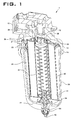
- FIG. 1 illustrates a canister filter system 1 having a base 10, a canister 20, and a filter element 30.
- the general construction and use of a canister filter system is understood by those of ordinary skill in this art. Thus, all the details of the construction and use of canister filter system 1 need not be explained here.
- the canister filter system 1 may be used to filter fluids such as diesel or gasoline or other liquid fuels, lubrication oil, hydraulic fluid for hydraulic power systems, transmission fluid, or even possibly intake air for an engine.
- the canister filter system 1 may also be used as a fuel/water separator filter.
- the canister filter system 1 with the features described herein could be adapted by those of ordinary skill in this art to serve many different purposes and suit many other applications.
- the base 10 includes an inlet channel 11 for fluid inlet into the canister filter system 1, and an outlet channel 12 for fluid outlet from the canister filter system 1.
- the base also includes base threads 13.
- the canister 20 includes an open end 21 and a closed end 22. Adjacent the open end 21 are canister threads 23 which can be engaged with base threads 13 to hold the canister 20 to base 10. Threads are one example of engagement structures which may be included on the base 10 and canister 20 to form a releasable engagement. Other engagement structures may be used as will be recognized by those of ordinary skill in this art.
- the filter element 30 may take many different forms to suit a particular application.
- the filter element 30 is well suited for filtering fuel or lubrication oil.
- the filter element 30 may include annularly arranged filter media 31 circumferentially surrounding a central reservoir defined by center tube 32. Axial ends of filter media 31 are sealed by end plates.
- Open end plate 33 defines an axial open end of filter element 30.
- the open end plate 33 is termed "open” because it includes an opening 35 for allowing passage of fluid to outlet channel 12 from the central reservoir defined by center tube 32.
- Closed end plate 34 defines an axial closed end of filter element 30.
- the closed end plate 34 is termed "closed” because it prevents any fluid outside the filter element 30 adjacent axial end of filter media 31 from flowing unfiltered into center tube 32.
- Open end plate 33 and closed end plate 34 may each be joined to the center tube 32 via welding, adhesives, etc. Alternatively, several or all of center tube 32, open end plate 33, and closed end plate 34 may be constructed as unitary components
- Fluid to be filtered enters from the inlet channel 11 and flows to the annular cavity 28 between canister 20 and filter media 31.
- the fluid then passes into and through filter media 31, then into center tube 32 through the perforations shown therein in FIG. 1 .
- the fluid exits center tube 32 through open end plate 33 and opening 35 into the outlet channel 12.
- the open end plate 33 and closed end plate 34 help define the fluid channels into and out of filter media 31, preventing any fluid from flowing directly to outlet channel 12 and bypassing filter media 31.
- First and second annular seals 38 and 39 may advantageously be included on filter element 30 and also help define and seal fluid passageways into and out of filter element 30.
- First annular seal 38 may be included on the open end plate 33 around opening 35 and adjacent the axial open end of filter element 30 to help seal the inlet channel 11 from the outlet channel 12.
- Second annular seal 39 larger in diameter than first annular seal 38, may be formed circumferentially around the open end plate 33 to provide the seal between canister 20 and base 10, or in other words provides a seal to prevent fluid in inlet channel 11 from leaking out of the joint between canister 20 and base 10.
- First and second annular seals 38, 39 may be integrally formed with open end plate 33, or attached with adhesives or other methods, as is known in this art. When first and second annular seals 38, 39 are integrally formed on or included on open end plate 33, proper replacement of these seals is assured when the filter element is replaced at proper intervals. Otherwise, a technician may fail to properly replace the seals at appropriate intervals, which could result in leakage out of the system, or leakage within the system allowing unfiltered fluid to bypass the filter element 31 and lead to contamination.
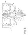
- a drain 40 penetrates the closed end 22 of canister 20.
- the drain 40 provides a drain channel 41 for removing fluid from inside of canister 20.
- the drain 40 is elongated and includes an inlet end 42 and an outlet end 43 connected to one another by the drain channel 41.
- Inlet end 42 is positioned inside of canister 20.
- Outlet end 43 is positioned outside of canister 20.
- the drain 40 may be moved between a closed position and an open position. In the closed position of FIG. 2 , fluid is not able to flow through drain channel 41. In the open position of FIG. 3 , fluid is able to flow from the inlet end 42, through drain channel 41, and out from outlet end 43. Drain 40 can be adapted to suit many different applications.
- the illustrated embodiment provides only one exemplary configuration for drain 40.
- Canister 20 includes a drain boss 24 on closed end 22.
- Drain boss 24 protrudes out and away from closed end 22, and may include surfaces thereon that would allow a tool, such as an adjustable, open-ended wrench, to engage the drain boss 24 and turn the canister 20.
- Drain boss 24 forms a bore 25.
- Drain 40 is positioned in, and is able to slide axially and rotate in bore 25.
- An O-ring groove 44 is formed around the exterior of drain 40 and an O-ring is positioned therein. Alternatively, the O-ring groove may be formed on the bore 25. The O-ring prevents fluid leakage out of canister 20 through bore 25 from between drain 40 and drain boss 24.
- Drain 40 may cooperate with filter element 30 to form a releasable engagement with filter element 30, and a releasable seal with filter element 30, when drain 40 is in its closed position.
- drain 40 forms a releasable engagement with filter element 30 through engagement structure that includes a releasable threaded connection.
- Closed end plate 34 may form a pocket 36 in which are provided threads 37. Threads 37 are formed on an inside surface of the pocket 36.
- Mutual threads 45 may be formed near inlet end 42 of drain 40.
- Drain 40 may be engaged with filter element 30 by threading together threads 37 and 45. Threads are one example of engagement structures which may be included on the filter element 30 and drain 40 to form a releasable engagement. Other known engagement structures may be used for particular advantage in certain applications as will be recognized by those of ordinary skill in this art.
- a releasable seal is made with filter element 30 so that practically no fluid can enter inlet end 42 of drain 40.
- the releasable seal is made with seal structure which, in the illustrated embodiment, includes an inlet opening 46 extending between drain channel 41 and the radial exterior of inlet end 42, and pocket 36 which receives the inlet opening 46 when the drain 40 is sealed.
- Putting drain 40 in its closed position moves inlet opening 46 inside of pocket 36, blocking the inlet opening 46 so that practically no fluid can enter therein.
- an O-ring groove 47 may be formed on drain 40 and an O-ring positioned therein.
- This O-ring may provide additional protection against fluid leaking from between drain 40 and pocket 36 and entering inlet opening 46.
- the O-ring could also be positioned between drain 40 and another portion of closed end plate 34, and the O-ring could be positioned in a groove formed on closed end plate 33 instead of on drain 40.
- Pocket 36 includes an open end 36a, a smooth section 36b, a threaded section 36c, and a closed end 36d. Closed end 36d ensures that no fluid may flow from center tube 32 into pocket 36 and inlet opening 46, and vice versa. Threads 37 are formed in the threaded section 36c. Smooth section 36b may act as a part of the sealing structure by fitting tightly against the surfaces of drain 40 to prevent fluid from entering between and flowing from open end 36a to inlet opening 46. Smooth section 36b may also provide a surface against which the O-ring in O-ring groove 47 may seal for additional protection against fluid passage.
- the diameter of this section may be larger than the major diameter of the threads 37, forming a lip 36e between the smooth section 36b and threaded section 36c.
- the larger diameter of smooth section 36b will help avoid the threads 45 on drain 40 from degrading the smooth surface used for sealing purposes.
- drain 40 When in an opened position, drain 40 is at least partially disengaged from filter element 30, and inlet opening 46 is open so that fluid may flow into drain channel 41.
- putting the drain 40 in an opened position requires turning drain 40 to disengage threads 37 and 45.
- threads 37 and 45 disengage, inlet end 42 of drain 40 advances out of pocket 36, unblocking inlet opening 46.
- Threads 37 and pocket 36 on filter element 30 need not necessarily be formed in closed end plate 34.
- the threads 37 and pocket 36 could also be formed as part of center tube 32, or some other part of filter element 30, as will be understood by those of ordinary skill in this art.
- filter element 30 and drain 40 could be constructed so that drain 40 makes a releasable seal with filter element 30 to close drain 40, but the two may not be releasably engaged.
- the filter element 30 and drain could be independently engaged with the canister 20, and moving drain 40 to a closed position would involve drain 40 moving upward to form a releasable seal with filter element 30, but not releasably engage it.
- the releasable engagement and the releasable seal between the drain 40 and the filter element 30 has several advantages. First, the engagement and/or seal ensure that a filter element 30 is placed inside canister 20 before the system can be used. A technician will not accidentally or intentionally assemble the system without a filter element 30 because without it, the drain 40 cannot be closed. Ensuring the presence of filter element 30 helps ensure that the fluid will be properly filtered.
- Threaded connections in the clean, filtered fluid pathway have been identified as a potential source of contamination.
- threads are cut or formed in other ways on a metal component, or even a plastic component, a small amount of debris is often left on the threads.
- the debris may be removed through the threading action, and is then free to enter the clean fluid pathway and result in contamination of downstream components.
- the avoidance of threads in the clean fluid pathway eliminates this potential source of contamination.
- threads on the filter element 30 provides a convenient means for repairing the threaded connection should the threads be crossed or damaged in some manner. If a threaded connection is between the canister 20 and drain 40 (as in prior art systems), either the canister 20 or the drain 40, or both, must be replaced if the threads are crossed or damaged in some other way. If threads 37 formed on filter element 30 are formed in plastic, while threads 45 on the drain 40 are formed in a harder material (possibly aluminum or another metal), when threads 37 and 45 are crossed, more than likely only threads 37 will be damaged. Threads 37 are easily replaceable by replacing the filter element 30. Finally, the engagement between the drain 40 and filter element 30 provides a means for securely holding the filter element inside the canister 20.
- Holding the filter element 30 inside of canister 20 may have some advantages during installation and replacement of the filter element 30.
- the canister 20 can be turned upside down by a technician to drain residual fluid therefrom, without the filter element 30 falling out.
- the filter element 30 can be held in the correct position inside of canister 20 so that when the canister 20 is attached to the base 10, the filter element 30 will properly align with features on the base 10.
- canister 20 may be simplified because no structure for engaging the drain (e.g. threads) is needed on the canister.
- Drain knob 50 facilitates turning drain 40 for moving between its closed and open positions. Drain knob 50 may be optionally positioned about drain 40 on the exterior of canister 20. Drain knob 50 includes splines 51 that mate with splines 48 formed on the exterior of drain 40. The splines 51, 48 allow drain knob 50 to move axially relative to drain 40 (along an axis parallel to the rotational axis of drain 40), but tie the two together rotationally. Turning drain knob 50 will cause a corresponding rotation of drain 40.
- drain knob 50 includes camming surfaces 52 that engage with mutual camming surfaces 26 on drain boss 24.
- a spring 53 acts between the drain 40 and the drain knob 50, biasing the camming surfaces 52 towards engagement with the camming surfaces 26.
- camming surfaces 52 and 26 engage one another, they permit the drain knob 50 to rotate relative the canister 20 in only a single direction.
- Camming surfaces 52 and 26 may be formed to permit rotation of drain knob 50 and drain 40 in the direction of its closed position (clockwise in the illustrated embodiment), but prohibit drain 40 to rotate in the opposite direction towards its open position unless camming surfaces 52 and 26 are disengaged. They may be disengaged by pulling drain knob 50 against the bias of spring 53, and separating the two camming surfaces 52, 26.
- the camming surfaces 52, 26 permit relative rotation in one direction by providing cams whereby the cams may slide by one another in one direction.
- the camming surfaces 52, 26 prohibit relative rotation in the other direction by providing positive stopping surfaces which interfere or clash.
- a spring 27 may optionally act between drain 40 and canister 20.
- Spring 27 biases the drain 40 into the canister 20. This may provide advantages in inserting and removing the filter element 30. For instance, in cooperation with the drain knob 50, biasing the drain 40 upwards causes the camming surfaces 52, 26 to engage and temporarily block rotation of the drain 40 in one direction. With spring 27 positioned as shown in the figures, and with camming surfaces 52 and 26, a technician can install a replacement filter element 30 in a simple manner by holding the canister 20 with one hand, and turning the filter element 30 with the other hand to engage the filter element 30 with the drain 40.
- the canister filter system 1 may be assembled by first positioning the filter element 30 inside the canister 20.
- the canister 20 includes an open end 21 through which the filter element 30 may pass, and a closed end 22.
- the drain 40 is caused to engage the filter element 30.
- the drain 40 passes through the bore 25 in the canister 20, with the inlet end 42 projecting into the canister to engage with the filter element 30.
- the filter element 30 and drain 40 are first fully engaged, which simultaneously moves the drain to a closed position, before the canister 20 is finally engaged with the base 10 to complete the assembly.
- first and second annular seals 38 and 39 integrally formed with or attached to filter element 30, many of the surfaces and seals which provide a sealing function in the system 1 will be replaced when the filter element 30 is replaced. This helps ensure the system 1 will function properly throughout its life.
- the canister filter system 1 may be used to filter contaminants from fluid systems including fuel systems, lubrication oil systems, hydraulic fluid power systems, hydraulic fluid control systems, transmission fluid systems, engine air intake systems, and the like, while permitting fluid to be conveniently drained using drain 40. Because of the arrangement of drain 40 with filter element 30, a technician is prevented from accidentally or intentionally operating system 1 unless a filter element 30 is in place. This operability limitation helps protect components which are sensitive to contamination.
Description
- The field of this disclosure is filter systems. More specifically, the field is canister filter systems for liquids, such as lube oil or liquid fuels, which have drains for draining liquid out of the canister.
- Canister filter systems are used extensively today on equipment such as internal combustion engines, construction and mining machinery, and many other types of industrial machinery. They are used to filter contaminants from fluids in fuel systems, lubrication oil systems, hydraulic fluid power systems, hydraulic fluid control systems, transmission fluid systems, engine air intake systems, and the like.
- A canister filter system typically includes a base which is often attached to the equipment, a canister (also sometimes called a housing, cup, can, or cover), and a filter element which is removably positioned inside the canister. After the filter element is positioned inside the canister, the canister is attached to the base with threads or other attachment means to form a sealed compartment around the filter element. The canister, base, and filter element cooperate to define fluid pathways through which fluid is directed through the filter element. The filter element contains filter media which traps and collects contaminants as the fluid passes through it. The trapped contaminants may include dirt, water, soot, ash, metallic particles, and other harmful debris.
- Eventually these contaminants clog the filter media and reduce its effectiveness. Or other conditions can develop over time which also reduce the effectiveness of the filter media in removing contaminants. When this occurs, the filter element should be replaced (or possibly cleaned, but this is impractical for most applications). But only the filter element needs to be replaced, while the canister, base, and other components are reused. The filter element is designed to be conveniently replaced and readily disposed. The filter element can be replaced on demand, i.e. when the filter becomes clogged and requires replacement, or periodically, according to the guidance of a periodic maintenance schedule established for the particular application.
- Canister filter systems can have many advantages over other filter systems such as spin-on filters. For instance, canister filter systems can be relatively inexpensively provided with a drain. To avoid spills, a technician may wish to remove the fluid from the canister in a controlled and contained manner before detaching the canister to replace the filter element. The drain facilitates the removal of fluid that is inside the canister. In some circumstances the fluid can spill if it is not first removed from the canister before detaching the canister from the base. The drain is typically integrated into the canister. Because in a canister filter system the drain generally increases just the cost of the canister, which is reused and purchased only once, and generally does not increase the cost of the filter element, which is frequently replaced and purchased many times, the additional cost of including a drain does not significantly increase the total operating cost to the equipment owner.
-
JP 09173716 A - Further,
US 5,366,400 A is directed to an oil filter cartridge having a valve, so that residual oil remaining in the filter cartridge can be drained by operating a valve. The oil filter cartridge with the valve is attached to an engine. A bag can be used to dispose of the used filter cartridge. -
U.S. Patent No. 6,814,243, granted 9 November 2004 , ("the '243 patent") is an example of prior art canister filter systems incorporating a drain in the canister.FIG. 1 of the '243 patent illustrates a canister 14 with an integrated drain (the drain is not labeled with a reference character, but is shown incorporated into the bottom of canister 14 inFIG. 1 , and is shown in a closed position). - The `243 patent is also an example of another, increasingly important feature of canister filter systems. The arrangement of the filter system described in the '243 patent makes it impossible to install the canister to the base, without first having a filter element properly installed in the canister. This prevents, for example, accidentally or intentionally running the machinery without the filter element in place. As components such as fuel pumps, fuel injectors, hydraulic pumps, valves, bearings, engines, etc., become more expensive, more high tech, and are made with tighter tolerances and specifications, it is increasingly important to protect these components against contamination. Contamination may cause premature wear and even failure, and the problem is compounded when the component has tight tolerances between parts or is very expensive. Thus, it may be very advantageous in some applications to ensure that a technician does not accidentally or intentionally try to run machinery without an appropriate filter element in place.
- However, while the filter system of the '243 patent performs well in some applications, it may suffer from several disadvantages, or is otherwise not well suited for other applications. For instance, the filter system of the '243 patent may not be well suited for applications where the fluid in the canister is at a high pressure. Because the connection of the canister to the base is through the filter element, the force of high pressure in the canister is reacted through the filter element, which may not be strong enough for the pressures of some applications. Additionally, O-ring between the canister and base is not intended to hold high pressure inside of the canister.
- The presence of threads in the filter element's center tube can be a disadvantage in some circumstances. The threads in the center tube, which are used to connect the filter element and canister to the base, are located in the clean fluid pathway out of the system. Threads in the clean fluid pathway may contribute to contamination.
- In addition, the canister of the system described in the '243 patent can be relatively complicated and expensive to manufacture for some applications. The connection structure incorporated into the bottom of the canister may add too much cost for some applications.
- Because of these drawbacks, another canister filter design is needed which still prevents accidentally or intentionally using the filter system without a filter element installed, but is also relieved of some or all of the disadvantages exhibited by the '243 patent.
- In accordance with the present invention, a filter element as set forth in
claim 1 is provided. Preferred embodiments of the invention are disclosed in the dependent claims. A canister filter system includes a base, a canister attachable to the base, and a filter element having filter media positioned inside the canister. A drain forms a seal with, and may releasably engage the filter element when the drain is in a closed position. In an open position, the drain allows fluid to be removed from the canister. Because the drain forms a seal with, and may releasably engage the filter element in the closed position, the drain cannot be closed unless a filter element is properly positioned inside the canister. This prevents accidental or intentional use of the filter system without a filter element in place. -
-
FIG. 1 is a cut away view of a canister filter system, including a base, a canister, and filter element. -
FIG. 2 is a detailed view fromFIG. 1 with thedrain 40 in a closed position. -
FIG. 3 is a detailed view fromFIG. 1 with thedrain 40 in an open position. - The following is a detailed description of exemplary embodiments of the invention. The exemplary embodiments described herein and illustrated in the drawing figures are intended to teach the principles of the invention, enabling those of ordinary skill in this art to make and use the invention in many different environments and for many different applications. The exemplary embodiments should not be considered as a limiting description of the scope of patent protection. The scope of patent protection shall be defined by the appended claims, and is intended to be broader than the specific embodiments described herein.
-
FIG. 1 illustrates acanister filter system 1 having abase 10, acanister 20, and afilter element 30. The general construction and use of a canister filter system is understood by those of ordinary skill in this art. Thus, all the details of the construction and use ofcanister filter system 1 need not be explained here. Thecanister filter system 1 may be used to filter fluids such as diesel or gasoline or other liquid fuels, lubrication oil, hydraulic fluid for hydraulic power systems, transmission fluid, or even possibly intake air for an engine. Thecanister filter system 1 may also be used as a fuel/water separator filter. Thecanister filter system 1 with the features described herein could be adapted by those of ordinary skill in this art to serve many different purposes and suit many other applications. - The
base 10 includes aninlet channel 11 for fluid inlet into thecanister filter system 1, and anoutlet channel 12 for fluid outlet from thecanister filter system 1. The base also includesbase threads 13. - The
canister 20 includes anopen end 21 and aclosed end 22. Adjacent theopen end 21 arecanister threads 23 which can be engaged withbase threads 13 to hold thecanister 20 tobase 10. Threads are one example of engagement structures which may be included on thebase 10 andcanister 20 to form a releasable engagement. Other engagement structures may be used as will be recognized by those of ordinary skill in this art. - The
filter element 30 may take many different forms to suit a particular application. In the illustrated embodiment, thefilter element 30 is well suited for filtering fuel or lubrication oil. Thefilter element 30 may include annularly arrangedfilter media 31 circumferentially surrounding a central reservoir defined bycenter tube 32. Axial ends offilter media 31 are sealed by end plates.Open end plate 33 defines an axial open end offilter element 30. Theopen end plate 33 is termed "open" because it includes anopening 35 for allowing passage of fluid tooutlet channel 12 from the central reservoir defined bycenter tube 32.Closed end plate 34 defines an axial closed end offilter element 30. Theclosed end plate 34 is termed "closed" because it prevents any fluid outside thefilter element 30 adjacent axial end offilter media 31 from flowing unfiltered intocenter tube 32.Open end plate 33 andclosed end plate 34 may each be joined to thecenter tube 32 via welding, adhesives, etc. Alternatively, several or all ofcenter tube 32,open end plate 33, andclosed end plate 34 may be constructed as unitary components. - Fluid to be filtered enters from the
inlet channel 11 and flows to theannular cavity 28 betweencanister 20 andfilter media 31. The fluid then passes into and throughfilter media 31, then intocenter tube 32 through the perforations shown therein inFIG. 1 . The fluid exitscenter tube 32 throughopen end plate 33 andopening 35 into theoutlet channel 12. Theopen end plate 33 andclosed end plate 34 help define the fluid channels into and out offilter media 31, preventing any fluid from flowing directly tooutlet channel 12 and bypassingfilter media 31. First and secondannular seals filter element 30 and also help define and seal fluid passageways into and out offilter element 30. Firstannular seal 38 may be included on theopen end plate 33 around opening 35 and adjacent the axial open end offilter element 30 to help seal theinlet channel 11 from theoutlet channel 12. Secondannular seal 39, larger in diameter than firstannular seal 38, may be formed circumferentially around theopen end plate 33 to provide the seal betweencanister 20 andbase 10, or in other words provides a seal to prevent fluid ininlet channel 11 from leaking out of the joint betweencanister 20 andbase 10. First and secondannular seals open end plate 33, or attached with adhesives or other methods, as is known in this art. When first and secondannular seals open end plate 33, proper replacement of these seals is assured when the filter element is replaced at proper intervals. Otherwise, a technician may fail to properly replace the seals at appropriate intervals, which could result in leakage out of the system, or leakage within the system allowing unfiltered fluid to bypass thefilter element 31 and lead to contamination. - With reference now to
FIGS. 2 and3 , adrain 40 penetrates theclosed end 22 ofcanister 20. Thedrain 40 provides adrain channel 41 for removing fluid from inside ofcanister 20. Thedrain 40 is elongated and includes aninlet end 42 and anoutlet end 43 connected to one another by thedrain channel 41.Inlet end 42 is positioned inside ofcanister 20.Outlet end 43 is positioned outside ofcanister 20. Thedrain 40 may be moved between a closed position and an open position. In the closed position ofFIG. 2 , fluid is not able to flow throughdrain channel 41. In the open position ofFIG. 3 , fluid is able to flow from theinlet end 42, throughdrain channel 41, and out fromoutlet end 43.Drain 40 can be adapted to suit many different applications. The illustrated embodiment provides only one exemplary configuration fordrain 40. -
Canister 20 includes adrain boss 24 onclosed end 22.Drain boss 24 protrudes out and away fromclosed end 22, and may include surfaces thereon that would allow a tool, such as an adjustable, open-ended wrench, to engage thedrain boss 24 and turn thecanister 20.Drain boss 24 forms abore 25.Drain 40 is positioned in, and is able to slide axially and rotate inbore 25. An O-ring groove 44 is formed around the exterior ofdrain 40 and an O-ring is positioned therein. Alternatively, the O-ring groove may be formed on thebore 25. The O-ring prevents fluid leakage out ofcanister 20 through bore 25 from betweendrain 40 anddrain boss 24. -
Drain 40 may cooperate withfilter element 30 to form a releasable engagement withfilter element 30, and a releasable seal withfilter element 30, whendrain 40 is in its closed position. In the illustrated embodiment, drain 40 forms a releasable engagement withfilter element 30 through engagement structure that includes a releasable threaded connection.Closed end plate 34 may form apocket 36 in which are providedthreads 37.Threads 37 are formed on an inside surface of thepocket 36.Mutual threads 45 may be formed nearinlet end 42 ofdrain 40.Drain 40 may be engaged withfilter element 30 by threading togetherthreads filter element 30 and drain 40 to form a releasable engagement. Other known engagement structures may be used for particular advantage in certain applications as will be recognized by those of ordinary skill in this art. - When in its closed position, with
drain 40 releasably engaged withfilter element 30, a releasable seal is made withfilter element 30 so that practically no fluid can enter inlet end 42 ofdrain 40. The releasable seal is made with seal structure which, in the illustrated embodiment, includes aninlet opening 46 extending betweendrain channel 41 and the radial exterior ofinlet end 42, andpocket 36 which receives theinlet opening 46 when thedrain 40 is sealed. Puttingdrain 40 in its closed position moves inlet opening 46 inside ofpocket 36, blocking the inlet opening 46 so that practically no fluid can enter therein. Additionally, an O-ring groove 47 may be formed ondrain 40 and an O-ring positioned therein. This O-ring may provide additional protection against fluid leaking from betweendrain 40 andpocket 36 and enteringinlet opening 46. Instead of positioning the O-ring inside ofpocket 36, the O-ring could also be positioned betweendrain 40 and another portion ofclosed end plate 34, and the O-ring could be positioned in a groove formed onclosed end plate 33 instead of ondrain 40. When movingdrain 40 to its closed position, as it advances intopocket 36, fluid trapped therein may need an escape path. This path may be provided by allowingdrain channel 41 to be open throughaxial inlet end 42 ofdrain 40. -
Pocket 36 includes anopen end 36a, asmooth section 36b, a threadedsection 36c, and aclosed end 36d.Closed end 36d ensures that no fluid may flow fromcenter tube 32 intopocket 36 andinlet opening 46, and vice versa.Threads 37 are formed in the threadedsection 36c.Smooth section 36b may act as a part of the sealing structure by fitting tightly against the surfaces ofdrain 40 to prevent fluid from entering between and flowing fromopen end 36a toinlet opening 46.Smooth section 36b may also provide a surface against which the O-ring in O-ring groove 47 may seal for additional protection against fluid passage. To help maintain the smoothness of the surface ofsmooth section 36b, the diameter of this section may be larger than the major diameter of thethreads 37, forming alip 36e between thesmooth section 36b and threadedsection 36c. The larger diameter ofsmooth section 36b will help avoid thethreads 45 ondrain 40 from degrading the smooth surface used for sealing purposes. - When in an opened position, drain 40 is at least partially disengaged from
filter element 30, and inlet opening 46 is open so that fluid may flow intodrain channel 41. In the illustrated embodiment with a threaded engagement, putting thedrain 40 in an opened position requires turningdrain 40 to disengagethreads threads drain 40 advances out ofpocket 36, unblockinginlet opening 46. Together, these features ensure that no fluid may enter inlet end 42 ofdrain 40 except when inlet opening 46 has backed out ofpocket 36, clearing thesmooth section 36b and theopen end 36a. Fluid is then free to flow frominside canister 20, through inlet opening 46, throughdrain channel 41, and exit through outlet end 43 ofdrain 40. -
Threads 37 andpocket 36 onfilter element 30 need not necessarily be formed inclosed end plate 34. Thethreads 37 andpocket 36 could also be formed as part ofcenter tube 32, or some other part offilter element 30, as will be understood by those of ordinary skill in this art. - Other features and constructions may be used to provide cooperation between
drain 40 andfilter element 30 so that fluid cannot flow throughdrain 40 whendrain 40 is in the closed position, and fluid may flow throughdrain 40 whendrain 40 is in the opened position. For example,filter element 30 and drain 40 could be constructed so thatdrain 40 makes a releasable seal withfilter element 30 to closedrain 40, but the two may not be releasably engaged. Instead, as an example, thefilter element 30 and drain could be independently engaged with thecanister 20, and movingdrain 40 to a closed position would involve drain 40 moving upward to form a releasable seal withfilter element 30, but not releasably engage it. - The releasable engagement and the releasable seal between the
drain 40 and thefilter element 30 has several advantages. First, the engagement and/or seal ensure that afilter element 30 is placed insidecanister 20 before the system can be used. A technician will not accidentally or intentionally assemble the system without afilter element 30 because without it, thedrain 40 cannot be closed. Ensuring the presence offilter element 30 helps ensure that the fluid will be properly filtered. - With no threaded connections in the pathway of clean fluid from the
center tube 32 to theoutlet channel 12, the possibility of contamination is reduced. Threaded connections in the clean, filtered fluid pathway have been identified as a potential source of contamination. When threads are cut or formed in other ways on a metal component, or even a plastic component, a small amount of debris is often left on the threads. When the threaded connection is made, the debris may be removed through the threading action, and is then free to enter the clean fluid pathway and result in contamination of downstream components. Thus, the avoidance of threads in the clean fluid pathway eliminates this potential source of contamination. - The provision of threads on the
filter element 30 provides a convenient means for repairing the threaded connection should the threads be crossed or damaged in some manner. If a threaded connection is between thecanister 20 and drain 40 (as in prior art systems), either thecanister 20 or thedrain 40, or both, must be replaced if the threads are crossed or damaged in some other way. Ifthreads 37 formed onfilter element 30 are formed in plastic, whilethreads 45 on thedrain 40 are formed in a harder material (possibly aluminum or another metal), whenthreads threads 37 will be damaged.Threads 37 are easily replaceable by replacing thefilter element 30. Finally, the engagement between thedrain 40 andfilter element 30 provides a means for securely holding the filter element inside thecanister 20. - Holding the
filter element 30 inside ofcanister 20 may have some advantages during installation and replacement of thefilter element 30. For example, thecanister 20 can be turned upside down by a technician to drain residual fluid therefrom, without thefilter element 30 falling out. Also, thefilter element 30 can be held in the correct position inside ofcanister 20 so that when thecanister 20 is attached to thebase 10, thefilter element 30 will properly align with features on thebase 10. - Other advantages may also be realized in some applications. In some applications, the manufacturing of
canister 20 may be simplified because no structure for engaging the drain (e.g. threads) is needed on the canister. -
Drain knob 50 facilitates turningdrain 40 for moving between its closed and open positions.Drain knob 50 may be optionally positioned aboutdrain 40 on the exterior ofcanister 20.Drain knob 50 includessplines 51 that mate withsplines 48 formed on the exterior ofdrain 40. Thesplines drain knob 50 to move axially relative to drain 40 (along an axis parallel to the rotational axis of drain 40), but tie the two together rotationally. Turningdrain knob 50 will cause a corresponding rotation ofdrain 40. - In addition,
drain knob 50 includes camming surfaces 52 that engage with mutual camming surfaces 26 ondrain boss 24. Aspring 53 acts between thedrain 40 and thedrain knob 50, biasing the camming surfaces 52 towards engagement with the camming surfaces 26. When camming surfaces 52 and 26 engage one another, they permit thedrain knob 50 to rotate relative thecanister 20 in only a single direction. Camming surfaces 52 and 26 may be formed to permit rotation ofdrain knob 50 and drain 40 in the direction of its closed position (clockwise in the illustrated embodiment), but prohibitdrain 40 to rotate in the opposite direction towards its open position unless camming surfaces 52 and 26 are disengaged. They may be disengaged by pullingdrain knob 50 against the bias ofspring 53, and separating the twocamming surfaces - A
spring 27 may optionally act betweendrain 40 andcanister 20.Spring 27 biases thedrain 40 into thecanister 20. This may provide advantages in inserting and removing thefilter element 30. For instance, in cooperation with thedrain knob 50, biasing thedrain 40 upwards causes the camming surfaces 52, 26 to engage and temporarily block rotation of thedrain 40 in one direction. Withspring 27 positioned as shown in the figures, and withcamming surfaces replacement filter element 30 in a simple manner by holding thecanister 20 with one hand, and turning thefilter element 30 with the other hand to engage thefilter element 30 with thedrain 40. - The
canister filter system 1 may be assembled by first positioning thefilter element 30 inside thecanister 20. Thecanister 20 includes anopen end 21 through which thefilter element 30 may pass, and aclosed end 22. Next thedrain 40 is caused to engage thefilter element 30. Thedrain 40 passes through thebore 25 in thecanister 20, with theinlet end 42 projecting into the canister to engage with thefilter element 30. Preferably, thefilter element 30 and drain 40 are first fully engaged, which simultaneously moves the drain to a closed position, before thecanister 20 is finally engaged with the base 10 to complete the assembly. - With first and second
annular seals 38 and 39 (seeFIG. 1 ) integrally formed with or attached to filterelement 30, many of the surfaces and seals which provide a sealing function in thesystem 1 will be replaced when thefilter element 30 is replaced. This helps ensure thesystem 1 will function properly throughout its life. - The
canister filter system 1 may be used to filter contaminants from fluid systems including fuel systems, lubrication oil systems, hydraulic fluid power systems, hydraulic fluid control systems, transmission fluid systems, engine air intake systems, and the like, while permitting fluid to be conveniently drained usingdrain 40. Because of the arrangement ofdrain 40 withfilter element 30, a technician is prevented from accidentally or intentionally operatingsystem 1 unless afilter element 30 is in place. This operability limitation helps protect components which are sensitive to contamination.
Claims (9)
- A filter element (30) comprising:annular filter media (31) surrounding a central reservoir, the filter media (31) allowing fluids to pass into the central reservoir but blocking the passage of impurities;an axial open end at a first end of the central reservoir with an opening (35) allowing fluid to flow from the central reservoir to the outside of the filter element (30), and a first annular seal (38) surrounding the opening;an axial closed end at a second end of the central reservoir opposite the first end wherein fluid may not pass through the axial closed end into or out of the central reservoir; anda pocket (36) formed adjacent the axial closed end for receiving a drain (40), the pocket (36) having threads (37) formed on an inside surface, the pocket (36) comprising an open end (36a), a threaded section (36c) including the threads (37), and a smooth section (36b) interposed between the open end (36a) and the threaded section (36c).
- A filter element (30) according to claim 1 further comprising a second annular seal (39), larger in diameter than the first annular seal (38), for sealing between a canister (20) and a base (10) when the filter element is installed in a canister filter system (1).
- A filter element (30) according to claim 2 wherein the axial open end includes an open end plate (34), the axial closed end includes a closed end plate (33), and the central reservoir is defined by a center tube (32), the center tube (32) being joined to the open end plate (34) and the closed end plate (33).
- A method of assembling a canister filter system (1) having a base (10), a canister (20), a filter element (30) as set forth in any of claims 1-3, and a drain (40) passing through a bore (25) in the canister (20), the method comprising:positioning the filter element (30) inside the canister (20);closing the drain (40) so that fluid cannot pass out of the canister (20) through the drain (40) by forming a releasable seal with the filter element (3 0); andengaging the canister (20) to the base (10) to define a flow path from the base (10), through the filter element (30), and back through the base (10).
- A method according to claim 4 further comprising forming a releasable engagement between the drain (40) and the filter element (30).
- A method according to claim 5 wherein forming a releasable engagement between the drain (40) and the filter element (30) comprises causing threads (45) formed on the drain (40) to engage with threads (37) formed on the filter element (30).
- A method according to claim 6 wherein forming a releasable seal with the filter element (30) comprises turning the drain (40) relative to the filter element (30) so that the threads (37) on the filter element further engage the threads (45) on the drain (40) until an inlet opening (46) formed on the drain (40) is blocked by the filter element (30).
- A method according to claim 7 wherein:positioning the filter element (30) inside the canister (20) comprises inserting the filter element (20) through an open end (21) of the canister (20); andengaging the canister (20) to the base (10) comprises engaging threads (23) formed adjacent the open end (21) of the canister (20) with threads (13) formed on the base (10).
- A canister filter system (1) comprising:a canister (20) having an open end (21) and a closed end (22);a drain (40) penetrating through the canister's closed end (22), the drain (40) having an inlet end (42) and an opposite outlet end (43), the inlet end (42) having seal structure formed thereon;a filter element (30) as set forth in any of claims 1-3 being insertable through the canister's open end (21) and positioned inside the canister (20),
and whereinthe drain (40) is movable between a closed position wherein the seal structure prevents fluid from flowing from the canister (20) into the drain's inlet end (42), and an open position wherein fluid may flow from the canister (20) into the drain's inlet end (42) and out of the drain's outlet end (43); andwhen the drain (40) is in its closed position, the seal structure on the inlet end of the drain (40) is engaged with the pocket (36) formed on the filter element (30) to form a releasable seal.
Applications Claiming Priority (2)
| Application Number | Priority Date | Filing Date | Title |
|---|---|---|---|
| US11/873,489 US8157997B2 (en) | 2007-10-17 | 2007-10-17 | Canister filter system with drain that cooperates with filter element |
| PCT/US2008/010982 WO2009051636A1 (en) | 2007-10-17 | 2008-09-19 | Canister filter system with drain that cooperates with filter element |
Publications (2)
| Publication Number | Publication Date |
|---|---|
| EP2136901A1 EP2136901A1 (en) | 2009-12-30 |
| EP2136901B1 true EP2136901B1 (en) | 2014-03-19 |
Family
ID=40418547
Family Applications (1)
| Application Number | Title | Priority Date | Filing Date |
|---|---|---|---|
| EP08839211.3A Active EP2136901B1 (en) | 2007-10-17 | 2008-09-19 | Canister filter system with drain that cooperates with filter element |
Country Status (13)
| Country | Link |
|---|---|
| US (3) | US8157997B2 (en) |
| EP (1) | EP2136901B1 (en) |
| JP (2) | JP5156098B2 (en) |
| CN (2) | CN101646478B (en) |
| AU (1) | AU2008312041B2 (en) |
| BR (1) | BRPI0816516B1 (en) |
| CA (1) | CA2701441C (en) |
| DE (1) | DE202008013578U1 (en) |
| DK (1) | DK2136901T3 (en) |
| ES (1) | ES2455018T3 (en) |
| RU (1) | RU2481877C2 (en) |
| WO (1) | WO2009051636A1 (en) |
| ZA (1) | ZA201002003B (en) |
Cited By (1)
| Publication number | Priority date | Publication date | Assignee | Title |
|---|---|---|---|---|
| WO2018202809A1 (en) | 2017-05-04 | 2018-11-08 | Mann+Hummel Gmbh | Filter element for liquid filtration |
Families Citing this family (26)
| Publication number | Priority date | Publication date | Assignee | Title |
|---|---|---|---|---|
| US8157997B2 (en) | 2007-10-17 | 2012-04-17 | Caterpillar Inc. | Canister filter system with drain that cooperates with filter element |
| US8501003B2 (en) * | 2007-10-17 | 2013-08-06 | Caterpillar Inc. | Canister filter system with drain that cooperates with filter element |
| US20120006731A1 (en) * | 2010-07-06 | 2012-01-12 | Swift Jr Edwin C | Filter with reusable bypass valve and inner assembly |
| EP2640497A1 (en) * | 2010-11-19 | 2013-09-25 | 3M Innovative Properties Company | Filtration system |
| DE102011120680A1 (en) * | 2011-12-08 | 2013-06-13 | Hydac Filtertechnik Gmbh | Filter device and filter element |
| DE102012009999A1 (en) * | 2012-05-22 | 2013-11-28 | Mann + Hummel Gmbh | Filter device for storing the water content in a liquid |
| DE102012209242A1 (en) * | 2012-05-31 | 2013-12-05 | Mahle International Gmbh | filtering device |
| DE102012018662A1 (en) * | 2012-09-21 | 2014-04-17 | Mann+Hummel Gmbh | Hollow-cylindrical filter element for a liquid filter |
| AU2014235855B2 (en) * | 2013-03-22 | 2017-09-07 | Caterpillar Inc. | Filter assembly |
| US20150060344A1 (en) * | 2013-08-29 | 2015-03-05 | Caterpillar Inc. | Canister filter system with drain that cooperates with filter element |
| CA2827580A1 (en) * | 2013-09-20 | 2015-03-20 | Peter Kerrin | Filter and system for removing emulsified water from a liquid |
| US9151424B2 (en) * | 2013-10-24 | 2015-10-06 | Caterpillar Inc. | Connector for connecting hose coupler to drain knob |
| US9302206B2 (en) * | 2014-03-31 | 2016-04-05 | Caterpillar Inc. | Filter assembly |
| DE102015108925B8 (en) * | 2015-06-05 | 2016-08-18 | Nidec Gpm Gmbh | Electrically driven liquid filter pump |
| US20170095759A1 (en) * | 2015-10-02 | 2017-04-06 | Caterpillar Inc. | Liquid Filter and Drain |
| US10272372B2 (en) | 2015-12-16 | 2019-04-30 | Caterpillar Inc. | Filter system using a self-venting drain |
| US20170189840A1 (en) | 2016-01-06 | 2017-07-06 | Caterpillar Inc. | Self-Venting Drain |
| CN109562308B (en) * | 2016-06-21 | 2021-09-14 | 沃尔沃卡车集团 | Filter element for a vehicle |
| CA3063528A1 (en) | 2017-06-19 | 2018-12-27 | Ingevity South Carolina, Llc | Evaporative fuel vapor emission control systems |
| US10729996B2 (en) * | 2018-11-01 | 2020-08-04 | Caterpillar Inc. | Drain assembly for a housing of a filter assembly |
| US11383188B2 (en) | 2019-06-07 | 2022-07-12 | Pall Corporation | Filter capsule and method of use |
| US11673078B2 (en) * | 2020-02-24 | 2023-06-13 | Caterpillar Inc. | Filter element locking mechanism |
| CN112198104B (en) * | 2020-09-30 | 2022-02-01 | 武汉大学 | Device and method for evaluating drainage performance of concealed pipe material |
| IL284529B (en) * | 2021-07-01 | 2021-12-01 | Tsabari Yigal | A water filter with self-rinsing capability |
| DE102022106933A1 (en) * | 2022-03-24 | 2023-09-28 | Mann+Hummel Gmbh | Filter element, filter element unit and filter |
| DE102022117115A1 (en) | 2022-07-08 | 2024-01-11 | Mann+Hummel Gmbh | Liquid filter, filter element and use of a filter element in a liquid filter |
Family Cites Families (105)
| Publication number | Priority date | Publication date | Assignee | Title |
|---|---|---|---|---|
| US2621796A (en) | 1948-02-09 | 1952-12-16 | Hastings Mfg Co | Oil filter |
| SU131295A1 (en) * | 1956-09-27 | 1959-11-30 | Л.Н. Солянкин | Dehumidifier with filter for continuous cleaning of gas from moisture and oil |
| US3166498A (en) | 1962-10-02 | 1965-01-19 | Jr Herbert R Otto | Oil filter with check valve |
| BE629037A (en) | 1963-04-19 | |||
| US3369666A (en) | 1965-09-22 | 1968-02-20 | Champion Lab Inc | Filter unit with anti-drain back valve means |
| DE1933283U (en) | 1965-12-20 | 1966-02-24 | Strebelwerk G M B H | COLLECTIVE HEATING BOILER IN THREE-INCLUSION DESIGN FOR FLOWING FUELS. |
| US4172795A (en) * | 1976-11-08 | 1979-10-30 | Friedrich Uhde Gmbh | Centrifugal pressure filter with horizontal filter disks |
| US4298465A (en) * | 1979-06-07 | 1981-11-03 | Racor Industries, Inc. | Fuel filter and water separator apparatus |
| JPS6026231Y2 (en) * | 1980-12-27 | 1985-08-07 | 株式会社土屋製作所 | Fuel filter center bolt structure |
| US4502956A (en) * | 1982-02-24 | 1985-03-05 | Racor Industries, Inc. | Filter assembly |
| US5547572A (en) * | 1985-05-14 | 1996-08-20 | Parker Hannifin Corporation | Fuel Filter |
| US4721563A (en) | 1986-09-11 | 1988-01-26 | Rosaen Borje O | Fluid filtering device |
| DE8714656U1 (en) * | 1987-11-04 | 1987-12-17 | Ing. Walter Hengst Gmbh & Co Kg, 4400 Muenster, De | |
| ATE103666T1 (en) * | 1989-10-04 | 1994-04-15 | Mann & Hummel Filter | LIQUID FILTER FOR THE LUBRICATION OIL OF AN ENGINE. |
| US5035797A (en) * | 1990-02-14 | 1991-07-30 | Stanadyne Automotive Corp. | Key system for filter assembly |
| DE4124322A1 (en) | 1991-07-23 | 1993-01-28 | Knecht Filterwerke Gmbh | Filter cartridge for motor vehicle engines - consisting of cup-shaped housing closed by circular plate and threaded ring and flange with seal in between |
| ES2095410T3 (en) * | 1991-08-16 | 1997-02-16 | Stanadyne Automotive Corp | DRY CHANGE SYSTEM OF A FUEL FILTER. |
| US5203994A (en) * | 1991-08-16 | 1993-04-20 | Stanadyne Automotive Corp. | Fuel filter retention system |
| ES2138962T3 (en) * | 1991-12-17 | 2000-02-01 | Mann & Hummel Filter | FILTER FOR FUELS AND / OR LUBRICANTS OF A COMBUSTION ENGINE. |
| US5300223A (en) * | 1992-01-27 | 1994-04-05 | Allied-Signal Inc. | Quick connect/disconnect oil filter |
| US5302284A (en) * | 1992-12-23 | 1994-04-12 | Stanadyne Automotive Corp. | Fuel filter with spring-loaded retention system |
| EP0616825A1 (en) * | 1993-03-17 | 1994-09-28 | Fram Europe Limited | Fluid filter assemblies |
| DE4310234C1 (en) * | 1993-03-30 | 1994-08-18 | Argo Feinmechanik | Backflow filter for liquids |
| DE9312051U1 (en) * | 1993-08-12 | 1993-10-14 | Hengst Walter Gmbh & Co Kg | Filter insert for a filter for filtering liquid or gaseous media |
| JPH0710407U (en) * | 1993-07-15 | 1995-02-14 | 東京濾器株式会社 | Oil filter |
| US5342519A (en) * | 1993-07-30 | 1994-08-30 | Donaldson Company, Inc. | Fluid filter cartridge with replaceable filter element |
| US6016923A (en) * | 1993-08-12 | 2000-01-25 | Ing. Walter Hengst Gmbh & Co. Kg | Filter cartridge for a filter for filtering liquid or gaseous media |
| WO1995007745A1 (en) * | 1993-09-15 | 1995-03-23 | Parker Hannifin Corporation | Fuel filter element |
| US5922199A (en) * | 1993-09-15 | 1999-07-13 | Parker Hannifin Corporation | Double pass fuel filter assembly |
| US6113781A (en) * | 1993-09-15 | 2000-09-05 | Parker-Hannifin Corporation | Fuel filter with dual flow |
| US5474676A (en) * | 1993-12-13 | 1995-12-12 | Stanadyne Automotive Corp. | Filter base assembly |
| US5484527A (en) * | 1993-12-13 | 1996-01-16 | Stanadyne Automotive Corp. | Module for filter assembly base |
| US5366400A (en) * | 1993-12-27 | 1994-11-22 | Michael Kucik | Apparatus and method for draining out the residual oil in a replaceable oil filter used in a marine engine for avoiding pollution to the environment when changing filters |
| CA2153737A1 (en) * | 1994-07-12 | 1996-01-13 | Mark A. Roll | Rebuildable spin-on filters |
| DE9411212U1 (en) * | 1994-07-13 | 1994-09-01 | Hengst Walter Gmbh & Co Kg | Liquid filter |
| US5458767A (en) * | 1994-08-10 | 1995-10-17 | Parker-Hannifin Corporation | Fuel filter assembly with dual filter media and by-pass device |
| DE4428771A1 (en) * | 1994-08-13 | 1996-02-15 | Mann & Hummel Filter | Filters, in particular for cleaning lubricating oil of an internal combustion engine |
| GB9423823D0 (en) * | 1994-11-25 | 1995-01-11 | Glacier Metal Co Ltd | Improvements in and relating to filtration |
| DE4443581C2 (en) * | 1994-12-09 | 1999-08-05 | Daimler Benz Ag | Liquid filters, especially fuel or oil filters |
| US5578221A (en) * | 1994-12-23 | 1996-11-26 | Stanadyne Automotive Corp. | Fuel filter with improved hand primer |
| DE19502020C2 (en) * | 1995-01-24 | 2002-02-28 | Mann & Hummel Filter | liquid filters |
| DE29623867U1 (en) | 1995-03-16 | 2000-05-25 | Hengst Walter Gmbh & Co Kg | Filter element for a liquid filter with filter bypass valve and sealing surface on the filter element side |
| US5548893A (en) * | 1995-03-20 | 1996-08-27 | Koelfgen; Douglas F. | Spin-on oil filter replacement element |
| DE19511450A1 (en) * | 1995-03-29 | 1996-10-02 | Argo Gmbh Fuer Fluidtechnik | Bypass filter unit |
| DE29509806U1 (en) * | 1995-06-16 | 1995-08-24 | Hengst Walter Gmbh & Co Kg | Liquid filter |
| US6068762A (en) * | 1995-09-29 | 2000-05-30 | Parker-Hannifin Corporation | Reusable oil filter assembly |
| FI98990C (en) | 1995-10-27 | 1997-09-25 | Parker Hannifinn Oy | Filter |
| DE19539918C1 (en) | 1995-10-27 | 1997-02-06 | Hengst Walter Gmbh & Co Kg | Liquid filter, in particular for oil or fuel of an internal combustion engine, and matching filter connection flange on the machine side |
| DE19540251C2 (en) * | 1995-10-28 | 1997-11-20 | Hengst Walter Gmbh & Co Kg | Coolant filter |
| WO1997016235A1 (en) | 1995-11-01 | 1997-05-09 | Parker-Hannifin Corporation | Filter housing and element therefor |
| GB2306342B (en) | 1995-11-02 | 2000-03-01 | Pall Corp | Filter assemblies and end caps for filter assemblies |
| US5660771A (en) * | 1995-11-29 | 1997-08-26 | Dana Corporation | Molding process for forming a sealing gasket on filter media |
| FI101201B (en) | 1995-12-14 | 1998-05-15 | Parker Hannifin Oy | Filter |
| US5738785A (en) * | 1995-12-20 | 1998-04-14 | Baldwin Filters, Inc. | Oil filter housing |
| US5702602A (en) * | 1995-12-20 | 1997-12-30 | Baldwin Filters, Inc. | Filter system with environmentally friendly filter cartridge |
| US5685985A (en) * | 1995-12-20 | 1997-11-11 | Baldwin Filters, Inc. | Environmentally friendly filter cartridge |
| JP3680396B2 (en) | 1995-12-27 | 2005-08-10 | 株式会社デンソー | Element exchange type filter |
| GB2309397B (en) * | 1996-01-25 | 2000-08-02 | Mann & Hummel Filter | Oil filter |
| DE29602330U1 (en) * | 1996-02-10 | 1996-05-30 | Hengst Walter Gmbh & Co Kg | Filter drain with spring lock |
| DE19606182A1 (en) * | 1996-02-20 | 1997-08-21 | Mann & Hummel Filter | Disconnecting device |
| DE19623190C2 (en) * | 1996-06-11 | 1998-07-30 | Hengst Walter Gmbh & Co Kg | Filter housing with non-uniform rib |
| US5858227A (en) * | 1996-09-23 | 1999-01-12 | Parker-Hannifin Corporation | Fuel filter assembly with in-line valve |
| DE19644646A1 (en) * | 1996-10-26 | 1998-04-30 | Mann & Hummel Filter | Filters, in particular for filtering the lubricating oil of an internal combustion engine |
| US5772881A (en) | 1996-11-08 | 1998-06-30 | Champion Laboratories, Inc. | Non-metallic spin-on filter |
| DE69724076T2 (en) | 1996-11-20 | 2004-06-09 | Denso Corp., Kariya | oil filter |
| US5785850A (en) | 1997-03-17 | 1998-07-28 | Certified Technologies Corp. | Cleanable oil filter |
| FR2762230B1 (en) | 1997-04-18 | 1999-07-16 | Fleetguard | FLEXIBLE FLANGE FILTER AND FILTER CARTRIDGE FOR FILTERING LIQUIDS FLOWING IN AN ENGINE OR IN HYDRAULIC EQUIPMENT |
| DE19731556A1 (en) * | 1997-07-23 | 1999-01-28 | Mann & Hummel Filter | Filter arrangement |
| US6045693A (en) | 1997-07-24 | 2000-04-04 | Fleetguard, Inc. | Spin-on filter assembly |
| JP3415410B2 (en) * | 1997-10-06 | 2003-06-09 | 株式会社 マーレ テネックス | Filters for liquid treatment |
| RU10110U1 (en) * | 1998-10-12 | 1999-06-16 | Акционерное общество открытого типа "Ульяновский автомобильный завод" | FILTER SILTER FOR CLEANING LIQUID |
| DE19847999A1 (en) * | 1998-10-17 | 2000-04-20 | Mann & Hummel Filter | Diesel fuel filter with automatic water disposal is used to pump under pressure dewater fuel to main filter |
| US6610203B1 (en) * | 1998-11-14 | 2003-08-26 | Filterwerk Mann & Hummel Gmbh | Liquid filter, particularly for oil or fuel in an internal combustion engine |
| US6322697B1 (en) | 1999-07-19 | 2001-11-27 | Donaldson Company, Inc. | Oil filter assembly |
| DE19934378A1 (en) * | 1999-07-22 | 2001-01-25 | Mann & Hummel Filter | Filter for filtering liquids, especially fuels, has riser pipe fixed in housing and provided with runback bore in geodetic upper region and runback channel |
| US6685829B1 (en) * | 1999-09-09 | 2004-02-03 | Ing. Walter Hengst Gmbh & Co. Kg | Fluid filter with a discharge dome that is fixed to the housing |
| BR0007048B1 (en) * | 1999-09-17 | 2009-08-11 | fluid filter. | |
| US6174438B1 (en) * | 1999-10-15 | 2001-01-16 | Parker-Hannifin Corporation | Dual pass fuel filter assembly and element therefor |
| DE19955635A1 (en) * | 1999-11-20 | 2001-05-31 | Argo Gmbh Fuer Fluidtechnik | Filtering device, for filtering hydraulic fluids, comprises filter housing containing filter element with partial filter elements |
| DE29921168U1 (en) * | 1999-12-02 | 2001-04-05 | Hengst Walter Gmbh & Co Kg | Liquid filter with removable, central component, with additional holding component |
| DE19961580A1 (en) * | 1999-12-21 | 2001-06-28 | Mann & Hummel Filter | Liquid filter with drain for liquid residues |
| DE60124331T2 (en) * | 2000-02-16 | 2007-02-15 | Stanadyne Corp., Windsor | Mounting system for ecological filter cartridge and filter element |
| DE60123499T2 (en) * | 2000-02-16 | 2007-05-03 | Stanadyne Corp., Windsor | Ecological filter cartridge for fuel and filter construction |
| DE20004431U1 (en) * | 2000-03-09 | 2000-06-21 | Mann & Hummel Filter | Liquid filter with bypass valve |
| DE20012736U1 (en) * | 2000-07-22 | 2000-09-21 | Mann & Hummel Filter | Assembly for an internal combustion engine with an oil filter |
| US6481580B1 (en) * | 2000-08-23 | 2002-11-19 | Caterpillar Inc | Fluid filter with locking mechanism |
| US6814243B2 (en) * | 2000-08-23 | 2004-11-09 | Caterpillar Inc | Replaceable filter with locking mechanism |
| US6591807B1 (en) * | 2000-08-25 | 2003-07-15 | Walter Hengst Gmbh & Co Kg | Combination comprising a main unit and at least one add-on functional unit |
| US6554140B2 (en) | 2000-12-19 | 2003-04-29 | Fleetguard, Inc. | Spin-on filter assembly |
| US6571962B2 (en) * | 2001-04-30 | 2003-06-03 | Fleetguard, Inc. | Cartridge filter element with housing seal retainer |
| US6607665B2 (en) * | 2001-07-17 | 2003-08-19 | Baldwin Filters, Inc. | Fuel filter element and cover assembly |
| US6974539B1 (en) | 2001-10-01 | 2005-12-13 | Wix Filtration Corp. | Combination filter element support and anti-prefill valve |
| US6740234B1 (en) * | 2002-03-05 | 2004-05-25 | Stanadyne Corporation | Key track system |
| US6729477B2 (en) | 2002-05-03 | 2004-05-04 | Arvin Technologies, Inc. | Fluid filter retainer and seal apparatus |
| US7168573B2 (en) * | 2002-06-07 | 2007-01-30 | Baldwin Filters, Inc. | Environmentally friendly filter cartridge |
| GB2389806B (en) * | 2002-06-07 | 2005-10-26 | Baldwin Filters Inc | Housing for environmentally friendly filter cartridge |
| US6972092B1 (en) * | 2003-05-16 | 2005-12-06 | Wix Filtration Corp. | Self-venting valve end cap and method |
| US20060091064A1 (en) | 2004-11-02 | 2006-05-04 | Baldwin Filters, Inc. | Filter apparatus with separable seal support frame |
| US20060096934A1 (en) | 2004-11-05 | 2006-05-11 | Weinberger Keith R | Oil filter assembly |
| DE102004058885B4 (en) * | 2004-12-06 | 2016-12-22 | Mann + Hummel Gmbh | Füssigkeitsfilter |
| EP1981608B1 (en) | 2006-02-09 | 2009-06-24 | Parker-Hannifin Corporation | Filter element with flow directing end cap |
| DE202006018334U1 (en) | 2006-12-04 | 2008-04-17 | Mann+Hummel Gmbh | Oil filter and filter element for such an oil filter |
| DE202006018335U1 (en) | 2006-12-04 | 2008-04-17 | Mann+Hummel Gmbh | Replaceable filter insert |
| DE112008001571B4 (en) * | 2007-06-18 | 2018-11-29 | Cummins Filtration Ip, Inc. | Fluid filter and method for servicing a fluid filter |
| US8157997B2 (en) | 2007-10-17 | 2012-04-17 | Caterpillar Inc. | Canister filter system with drain that cooperates with filter element |
-
2007
- 2007-10-17 US US11/873,489 patent/US8157997B2/en active Active
-
2008
- 2008-09-19 WO PCT/US2008/010982 patent/WO2009051636A1/en active Application Filing
- 2008-09-19 BR BRPI0816516 patent/BRPI0816516B1/en active IP Right Grant
- 2008-09-19 RU RU2010119507/05A patent/RU2481877C2/en active
- 2008-09-19 ES ES08839211.3T patent/ES2455018T3/en active Active
- 2008-09-19 AU AU2008312041A patent/AU2008312041B2/en active Active
- 2008-09-19 JP JP2010529914A patent/JP5156098B2/en active Active
- 2008-09-19 CN CN2008800105398A patent/CN101646478B/en active Active
- 2008-09-19 CA CA2701441A patent/CA2701441C/en active Active
- 2008-09-19 DK DK08839211.3T patent/DK2136901T3/en active
- 2008-09-19 EP EP08839211.3A patent/EP2136901B1/en active Active
- 2008-10-13 DE DE202008013578U patent/DE202008013578U1/en not_active Expired - Lifetime
- 2008-10-17 CN CNU2008202099628U patent/CN201361481Y/en not_active Expired - Lifetime
-
2010
- 2010-03-19 ZA ZA2010/02003A patent/ZA201002003B/en unknown
-
2011
- 2011-09-16 US US13/235,306 patent/US8460545B2/en active Active
- 2011-09-16 US US13/235,332 patent/US8535529B2/en active Active
-
2012
- 2012-12-07 JP JP2012268250A patent/JP5390687B2/en active Active
Cited By (1)
| Publication number | Priority date | Publication date | Assignee | Title |
|---|---|---|---|---|
| WO2018202809A1 (en) | 2017-05-04 | 2018-11-08 | Mann+Hummel Gmbh | Filter element for liquid filtration |
Also Published As
| Publication number | Publication date |
|---|---|
| WO2009051636A1 (en) | 2009-04-23 |
| DE202008013578U1 (en) | 2009-03-05 |
| AU2008312041B2 (en) | 2013-05-30 |
| CA2701441C (en) | 2013-10-29 |
| RU2481877C2 (en) | 2013-05-20 |
| CN101646478B (en) | 2013-09-18 |
| US20120000841A1 (en) | 2012-01-05 |
| US20120000056A1 (en) | 2012-01-05 |
| CA2701441A1 (en) | 2009-04-23 |
| US20090101595A1 (en) | 2009-04-23 |
| ES2455018T3 (en) | 2014-04-14 |
| CN101646478A (en) | 2010-02-10 |
| CN201361481Y (en) | 2009-12-16 |
| JP5156098B2 (en) | 2013-03-06 |
| BRPI0816516B1 (en) | 2019-12-10 |
| JP5390687B2 (en) | 2014-01-15 |
| ZA201002003B (en) | 2011-05-25 |
| AU2008312041A1 (en) | 2009-04-23 |
| JP2013063437A (en) | 2013-04-11 |
| US8535529B2 (en) | 2013-09-17 |
| US8157997B2 (en) | 2012-04-17 |
| JP2011502035A (en) | 2011-01-20 |
| US8460545B2 (en) | 2013-06-11 |
| DK2136901T3 (en) | 2014-05-12 |
| BRPI0816516A2 (en) | 2019-03-06 |
| RU2010119507A (en) | 2011-11-27 |
| EP2136901A1 (en) | 2009-12-30 |
Similar Documents
| Publication | Publication Date | Title |
|---|---|---|
| EP2136901B1 (en) | Canister filter system with drain that cooperates with filter element | |
| US9511314B2 (en) | Canister filter system with drain that cooperates with filter element | |
| RU2743081C2 (en) | Locking element for filtering element cleaning | |
| RU2732543C2 (en) | Filtering element and filtering device | |
| US20140124459A1 (en) | No filter no run feature for filter | |
| CA2758905A1 (en) | Combination of a filter element and a core element, and a filter element | |
| US20150060344A1 (en) | Canister filter system with drain that cooperates with filter element | |
| BR112013007784B1 (en) | FILTER ELEMENT |
Legal Events
| Date | Code | Title | Description |
|---|---|---|---|
| PUAI | Public reference made under article 153(3) epc to a published international application that has entered the european phase |
Free format text: ORIGINAL CODE: 0009012 |
|
| 17P | Request for examination filed |
Effective date: 20090915 |
|
| AK | Designated contracting states |
Kind code of ref document: A1 Designated state(s): AT BE BG CH CY CZ DE DK EE ES FI FR GB GR HR HU IE IS IT LI LT LU LV MC MT NL NO PL PT RO SE SI SK TR |
|
| 17Q | First examination report despatched |
Effective date: 20100226 |
|
| R17C | First examination report despatched (corrected) |
Effective date: 20100511 |
|
| DAX | Request for extension of the european patent (deleted) | ||
| GRAP | Despatch of communication of intention to grant a patent |
Free format text: ORIGINAL CODE: EPIDOSNIGR1 |
|
| INTG | Intention to grant announced |
Effective date: 20131004 |
|
| GRAS | Grant fee paid |
Free format text: ORIGINAL CODE: EPIDOSNIGR3 |
|
| GRAA | (expected) grant |
Free format text: ORIGINAL CODE: 0009210 |
|
| AK | Designated contracting states |
Kind code of ref document: B1 Designated state(s): AT BE BG CH CY CZ DE DK EE ES FI FR GB GR HR HU IE IS IT LI LT LU LV MC MT NL NO PL PT RO SE SI SK TR |
|
| REG | Reference to a national code |
Ref country code: GB Ref legal event code: FG4D |
|
| REG | Reference to a national code |
Ref country code: RO Ref legal event code: EPE |
|
| REG | Reference to a national code |
Ref country code: CH Ref legal event code: EP |
|
| REG | Reference to a national code |
Ref country code: IE Ref legal event code: FG4D |
|
| REG | Reference to a national code |
Ref country code: ES Ref legal event code: FG2A Ref document number: 2455018 Country of ref document: ES Kind code of ref document: T3 Effective date: 20140414 |
|
| REG | Reference to a national code |
Ref country code: AT Ref legal event code: REF Ref document number: 657268 Country of ref document: AT Kind code of ref document: T Effective date: 20140415 |
|
| REG | Reference to a national code |
Ref country code: DE Ref legal event code: R096 Ref document number: 602008031007 Country of ref document: DE Effective date: 20140430 |
|
| REG | Reference to a national code |
Ref country code: NL Ref legal event code: T3 |
|
| REG | Reference to a national code |
Ref country code: DK Ref legal event code: T3 Effective date: 20140506 |
|
| REG | Reference to a national code |
Ref country code: CH Ref legal event code: NV Representative=s name: KATZAROV S.A., CH |
|
| REG | Reference to a national code |
Ref country code: NO Ref legal event code: T2 Effective date: 20140319 |
|
| REG | Reference to a national code |
Ref country code: GR Ref legal event code: EP Ref document number: 20140400806 Country of ref document: GR Effective date: 20140515 |
|
| PG25 | Lapsed in a contracting state [announced via postgrant information from national office to epo] |
Ref country code: LT Free format text: LAPSE BECAUSE OF FAILURE TO SUBMIT A TRANSLATION OF THE DESCRIPTION OR TO PAY THE FEE WITHIN THE PRESCRIBED TIME-LIMIT Effective date: 20140319 |
|
| REG | Reference to a national code |
Ref country code: LT Ref legal event code: MG4D |
|
| PG25 | Lapsed in a contracting state [announced via postgrant information from national office to epo] |
Ref country code: CY Free format text: LAPSE BECAUSE OF FAILURE TO SUBMIT A TRANSLATION OF THE DESCRIPTION OR TO PAY THE FEE WITHIN THE PRESCRIBED TIME-LIMIT Effective date: 20140319 Ref country code: SE Free format text: LAPSE BECAUSE OF FAILURE TO SUBMIT A TRANSLATION OF THE DESCRIPTION OR TO PAY THE FEE WITHIN THE PRESCRIBED TIME-LIMIT Effective date: 20140319 |
|
| PG25 | Lapsed in a contracting state [announced via postgrant information from national office to epo] |
Ref country code: HR Free format text: LAPSE BECAUSE OF FAILURE TO SUBMIT A TRANSLATION OF THE DESCRIPTION OR TO PAY THE FEE WITHIN THE PRESCRIBED TIME-LIMIT Effective date: 20140319 Ref country code: LV Free format text: LAPSE BECAUSE OF FAILURE TO SUBMIT A TRANSLATION OF THE DESCRIPTION OR TO PAY THE FEE WITHIN THE PRESCRIBED TIME-LIMIT Effective date: 20140319 |
|
| PG25 | Lapsed in a contracting state [announced via postgrant information from national office to epo] |
Ref country code: EE Free format text: LAPSE BECAUSE OF FAILURE TO SUBMIT A TRANSLATION OF THE DESCRIPTION OR TO PAY THE FEE WITHIN THE PRESCRIBED TIME-LIMIT Effective date: 20140319 |
|
| PG25 | Lapsed in a contracting state [announced via postgrant information from national office to epo] |
Ref country code: SK Free format text: LAPSE BECAUSE OF FAILURE TO SUBMIT A TRANSLATION OF THE DESCRIPTION OR TO PAY THE FEE WITHIN THE PRESCRIBED TIME-LIMIT Effective date: 20140319 Ref country code: PL Free format text: LAPSE BECAUSE OF FAILURE TO SUBMIT A TRANSLATION OF THE DESCRIPTION OR TO PAY THE FEE WITHIN THE PRESCRIBED TIME-LIMIT Effective date: 20140319 |
|
| REG | Reference to a national code |
Ref country code: DE Ref legal event code: R026 Ref document number: 602008031007 Country of ref document: DE |
|
| REG | Reference to a national code |
Ref country code: HU Ref legal event code: AG4A Ref document number: E021062 Country of ref document: HU |
|
| PG25 | Lapsed in a contracting state [announced via postgrant information from national office to epo] |
Ref country code: PT Free format text: LAPSE BECAUSE OF FAILURE TO SUBMIT A TRANSLATION OF THE DESCRIPTION OR TO PAY THE FEE WITHIN THE PRESCRIBED TIME-LIMIT Effective date: 20140721 |
|
| PLBI | Opposition filed |
Free format text: ORIGINAL CODE: 0009260 |
|
| PLAX | Notice of opposition and request to file observation + time limit sent |
Free format text: ORIGINAL CODE: EPIDOSNOBS2 |
|
| 26 | Opposition filed |
Opponent name: DE BAAT, MICHEL Effective date: 20141219 |
|
| REG | Reference to a national code |
Ref country code: DE Ref legal event code: R026 Ref document number: 602008031007 Country of ref document: DE Effective date: 20141219 |
|
| PG25 | Lapsed in a contracting state [announced via postgrant information from national office to epo] |
Ref country code: LU Free format text: LAPSE BECAUSE OF FAILURE TO SUBMIT A TRANSLATION OF THE DESCRIPTION OR TO PAY THE FEE WITHIN THE PRESCRIBED TIME-LIMIT Effective date: 20140919 Ref country code: MC Free format text: LAPSE BECAUSE OF FAILURE TO SUBMIT A TRANSLATION OF THE DESCRIPTION OR TO PAY THE FEE WITHIN THE PRESCRIBED TIME-LIMIT Effective date: 20140319 |
|
| PLAF | Information modified related to communication of a notice of opposition and request to file observations + time limit |
Free format text: ORIGINAL CODE: EPIDOSCOBS2 |
|
| REG | Reference to a national code |
Ref country code: IE Ref legal event code: MM4A |
|
| REG | Reference to a national code |
Ref country code: FR Ref legal event code: PLFP Year of fee payment: 8 |
|
| PG25 | Lapsed in a contracting state [announced via postgrant information from national office to epo] |
Ref country code: SI Free format text: LAPSE BECAUSE OF FAILURE TO SUBMIT A TRANSLATION OF THE DESCRIPTION OR TO PAY THE FEE WITHIN THE PRESCRIBED TIME-LIMIT Effective date: 20140319 |
|
| PLBB | Reply of patent proprietor to notice(s) of opposition received |
Free format text: ORIGINAL CODE: EPIDOSNOBS3 |
|
| PG25 | Lapsed in a contracting state [announced via postgrant information from national office to epo] |
Ref country code: IE Free format text: LAPSE BECAUSE OF NON-PAYMENT OF DUE FEES Effective date: 20140919 |
|
| PLAB | Opposition data, opponent's data or that of the opponent's representative modified |
Free format text: ORIGINAL CODE: 0009299OPPO |
|
| R26 | Opposition filed (corrected) |
Opponent name: DE BAAT, MICHIEL Effective date: 20141219 |
|
| PG25 | Lapsed in a contracting state [announced via postgrant information from national office to epo] |
Ref country code: MT Free format text: LAPSE BECAUSE OF FAILURE TO SUBMIT A TRANSLATION OF THE DESCRIPTION OR TO PAY THE FEE WITHIN THE PRESCRIBED TIME-LIMIT Effective date: 20140319 |
|
| REG | Reference to a national code |
Ref country code: FR Ref legal event code: PLFP Year of fee payment: 9 |
|
| REG | Reference to a national code |
Ref country code: DE Ref legal event code: R100 Ref document number: 602008031007 Country of ref document: DE |
|
| PLCK | Communication despatched that opposition was rejected |
Free format text: ORIGINAL CODE: EPIDOSNREJ1 |
|
| STAA | Information on the status of an ep patent application or granted ep patent |
Free format text: STATUS: THE PATENT HAS BEEN GRANTED |
|
| PLBN | Opposition rejected |
Free format text: ORIGINAL CODE: 0009273 |
|
| STAA | Information on the status of an ep patent application or granted ep patent |
Free format text: STATUS: OPPOSITION REJECTED |
|
| 27O | Opposition rejected |
Effective date: 20170124 |
|
| REG | Reference to a national code |
Ref country code: FR Ref legal event code: PLFP Year of fee payment: 10 |
|
| REG | Reference to a national code |
Ref country code: HU Ref legal event code: HC9C |
|
| REG | Reference to a national code |
Ref country code: CH Ref legal event code: PCAR Free format text: NEW ADDRESS: AVENUE DES MORGINES 12, 1213 PETIT-LANCY (CH) |
|
| REG | Reference to a national code |
Ref country code: FR Ref legal event code: PLFP Year of fee payment: 11 |
|
| REG | Reference to a national code |
Ref country code: HU Ref legal event code: HC9C Owner name: CATERPILLAR, INC., US |
|
| REG | Reference to a national code |
Ref country code: HU Ref legal event code: HC9C Owner name: CATERPILLAR, INC., US |
|
| P01 | Opt-out of the competence of the unified patent court (upc) registered |
Effective date: 20230517 |
|
| PGFP | Annual fee paid to national office [announced via postgrant information from national office to epo] |
Ref country code: NL Payment date: 20230822 Year of fee payment: 16 |
|
| PGFP | Annual fee paid to national office [announced via postgrant information from national office to epo] |
Ref country code: TR Payment date: 20230823 Year of fee payment: 16 Ref country code: RO Payment date: 20230913 Year of fee payment: 16 Ref country code: NO Payment date: 20230823 Year of fee payment: 16 Ref country code: IT Payment date: 20230822 Year of fee payment: 16 Ref country code: GB Payment date: 20230823 Year of fee payment: 16 Ref country code: FI Payment date: 20230823 Year of fee payment: 16 Ref country code: CZ Payment date: 20230825 Year of fee payment: 16 Ref country code: BG Payment date: 20230828 Year of fee payment: 16 Ref country code: AT Payment date: 20230823 Year of fee payment: 16 |
|
| PGFP | Annual fee paid to national office [announced via postgrant information from national office to epo] |
Ref country code: IS Payment date: 20230915 Year of fee payment: 16 Ref country code: HU Payment date: 20230829 Year of fee payment: 16 Ref country code: GR Payment date: 20230823 Year of fee payment: 16 Ref country code: FR Payment date: 20230822 Year of fee payment: 16 Ref country code: DK Payment date: 20230822 Year of fee payment: 16 Ref country code: DE Payment date: 20230822 Year of fee payment: 16 Ref country code: BE Payment date: 20230822 Year of fee payment: 16 |
|
| PGFP | Annual fee paid to national office [announced via postgrant information from national office to epo] |
Ref country code: ES Payment date: 20231002 Year of fee payment: 16 |
|
| PGFP | Annual fee paid to national office [announced via postgrant information from national office to epo] |
Ref country code: CH Payment date: 20231001 Year of fee payment: 16 |