EP2138108A1 - Puncturing needle assisting tool - Google Patents
Puncturing needle assisting tool Download PDFInfo
- Publication number
- EP2138108A1 EP2138108A1 EP09008041A EP09008041A EP2138108A1 EP 2138108 A1 EP2138108 A1 EP 2138108A1 EP 09008041 A EP09008041 A EP 09008041A EP 09008041 A EP09008041 A EP 09008041A EP 2138108 A1 EP2138108 A1 EP 2138108A1
- Authority
- EP
- European Patent Office
- Prior art keywords
- rotating
- main unit
- assisting tool
- puncturing needle
- guide grooves
- Prior art date
- Legal status (The legal status is an assumption and is not a legal conclusion. Google has not performed a legal analysis and makes no representation as to the accuracy of the status listed.)
- Granted
Links
Images


Classifications
-
- A—HUMAN NECESSITIES
- A61—MEDICAL OR VETERINARY SCIENCE; HYGIENE
- A61B—DIAGNOSIS; SURGERY; IDENTIFICATION
- A61B17/00—Surgical instruments, devices or methods, e.g. tourniquets
- A61B17/04—Surgical instruments, devices or methods, e.g. tourniquets for suturing wounds; Holders or packages for needles or suture materials
- A61B17/0482—Needle or suture guides
-
- A—HUMAN NECESSITIES
- A61—MEDICAL OR VETERINARY SCIENCE; HYGIENE
- A61B—DIAGNOSIS; SURGERY; IDENTIFICATION
- A61B17/00—Surgical instruments, devices or methods, e.g. tourniquets
- A61B17/04—Surgical instruments, devices or methods, e.g. tourniquets for suturing wounds; Holders or packages for needles or suture materials
- A61B17/0485—Devices or means, e.g. loops, for capturing the suture thread and threading it through an opening of a suturing instrument or needle eyelet
-
- A—HUMAN NECESSITIES
- A61—MEDICAL OR VETERINARY SCIENCE; HYGIENE
- A61B—DIAGNOSIS; SURGERY; IDENTIFICATION
- A61B17/00—Surgical instruments, devices or methods, e.g. tourniquets
- A61B17/04—Surgical instruments, devices or methods, e.g. tourniquets for suturing wounds; Holders or packages for needles or suture materials
- A61B17/06—Needles ; Sutures; Needle-suture combinations; Holders or packages for needles or suture materials
- A61B17/06061—Holders for needles or sutures, e.g. racks, stands
-
- A—HUMAN NECESSITIES
- A61—MEDICAL OR VETERINARY SCIENCE; HYGIENE
- A61B—DIAGNOSIS; SURGERY; IDENTIFICATION
- A61B50/00—Containers, covers, furniture or holders specially adapted for surgical or diagnostic appliances or instruments, e.g. sterile covers
- A61B50/20—Holders specially adapted for surgical or diagnostic appliances or instruments
- A61B50/22—Racks
-
- A—HUMAN NECESSITIES
- A61—MEDICAL OR VETERINARY SCIENCE; HYGIENE
- A61B—DIAGNOSIS; SURGERY; IDENTIFICATION
- A61B17/00—Surgical instruments, devices or methods, e.g. tourniquets
- A61B17/04—Surgical instruments, devices or methods, e.g. tourniquets for suturing wounds; Holders or packages for needles or suture materials
- A61B17/0469—Suturing instruments for use in minimally invasive surgery, e.g. endoscopic surgery
-
- A—HUMAN NECESSITIES
- A61—MEDICAL OR VETERINARY SCIENCE; HYGIENE
- A61B—DIAGNOSIS; SURGERY; IDENTIFICATION
- A61B17/00—Surgical instruments, devices or methods, e.g. tourniquets
- A61B17/04—Surgical instruments, devices or methods, e.g. tourniquets for suturing wounds; Holders or packages for needles or suture materials
- A61B17/06—Needles ; Sutures; Needle-suture combinations; Holders or packages for needles or suture materials
- A61B2017/06052—Needle-suture combinations in which a suture is extending inside a hollow tubular needle, e.g. over the entire length of the needle
Definitions
- the present invention generally relates to a puncturing needle assisting tool that is used when puncturing tissue with a plurality of puncturing needles and is used for securing an internal organ onto a skin side portion using surgical sutures.
- gastric catheters are used to supply liquid diets, such as liquid foods or nutritional supplements, or the like, into the stomachs of the patients.
- a gastric catheter is attached by forming an opening portion in the abdomen of the patient.
- the abdominal wall and the gastric wall are secured together in advance using sutures.
- the technology for securing the gastric wall to the abdominal wall is well known in the prior art (see Japanese Patent Application 2008-164032 , for example).
- holes are provided in an insertion length adjusting plate, into which a needle comprising a suture thread insertion needle and an outer needle for securing an internal organ, such as the gastric wall, to the abdominal wall can fit.
- a constant interval is maintained by connecting, via a connecting plate, the outer needle and the suture thread insertion needle.
- the insertion depth of each needle is adjusted to the via an insertion depth adjusting plate slidable in an axial direction of the needles.
- the needle puncturing operation is performed simultaneously with the joining together of the suture thread insertion needle and the outer needle. First, the outer needle and the suture thread insertion needle penetrate through the abdominal wall and gastric wall to puncture the gastric lumen.
- an inner needle within the outer needle is slid inwards so that a snare loop at the tip of the inner needle protrudes, in a direction that is perpendicular to the axial direction of the needles and from a tip hole portion of the needle.
- a thread is introduced into the suture thread insertion needle, and the tip portion of the thread passes through the inside of the snare loop. Withdrawing the inner needle draws the snare loop into the outer needle.
- the inner needle is removed from the body, and with both ends of the thread extracted from the body, both the outer needle and the suture thread insertion needle are removed.
- the thread is tied by an operation of applying a tensile force to both ends of the thread, to cause the gastric wall to be in contact with the abdominal wall, thereby enabling a tight seal therebetween.
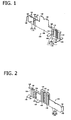
- FIG. 1 is a perspective view of a front surface side of a puncturing needle assisting tool according to a first embodiment of the invention.
- FIG. 2 is a perspective view of a back surface side of the puncturing needle assisting tool according to the first embodiment of the invention.
- FIG. 3 is a front (a) and back (b) view of the puncturing needle assisting tool according to the first embodiment.
- FIG. 4 is a top (a) and bottom (b) view of the puncturing needle assisting tool according to the first embodiment.
- FIG. 5 is a left side (a) and right side (b) view of the puncturing needle assisting tool according to the first embodiment.
- FIG. 6(a ) is a top view of the puncturing needle assisting tool according to the first embodiment showing a first rotating portion in the closed position and a second rotating portion in the open position.
- FIG. 6(b ) is a top view of the puncturing needle assisting tool according to the first embodiment showing both the first rotating portion and the second rotating portion in the closed position.
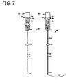
- FIG. 7(a) is a top view of an insertion puncturing needle.
- FIG. 7(b) is a top view of an extraction puncturing needle.
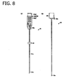
- FIG. 8(a) is a top view of an outer insertion puncturing needle.
- FIG. 8(b) is a top view of an inner insertion puncturing needle.
- FIG. 9(a) is a top view of an outer extraction puncturing needle.
- FIG. 9(b) is a top view of an inner extraction puncturing needle.
- FIG. 9(c) is a top view of a snare portion of the inner extraction puncturing needle.
- FIG. 10(a) is a top view showing a protector attached to the insertion puncturing needle.
- FIG. 10(b) is a top view showing the protector attached to the extraction puncturing needle.
- FIG. 11 is a top view of the puncturing needle assisting tool according to the first embodiment placed on the surface of the skin of the abdomen.
- FIG. 12 is a top view of the puncturing needle assisting tool according to the first embodiment wherein the extraction puncturing needle is placed in a guide groove.
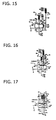
- FIG. 13 is a top view of the puncturing needle assisting tool according to the first embodiment wherein the extraction puncturing needle is placed in the guide groove and the first rotating portion is rotated to a surface side of the assisting tool main unit.
- FIG. 14 is a top view of the puncturing needle assisting tool according to the first embodiment wherein the extraction puncturing needle has pierced the abdomen.
- FIG. 15 is a top view of the puncturing needle assisting tool according to the first embodiment wherein the snare portion of the inner extraction puncturing needle is spread in the shape of a loop within the stomach.
- FIG. 16 is a top view of the puncturing needle assisting tool according to the first embodiment wherein an outer insertion puncturing needle is placed in the guide groove and the second rotating portion is rotated to the surface side of the assisting tool main unit.
- FIG. 17 is a top view of the puncturing needle assisting tool according to the first embodiment wherein the outer insertion puncturing needle has pierced the abdomen.
- FIG. 18 is a top view of the puncturing needle assisting tool according to the first embodiment wherein a suture thread is inserted into the outer insertion puncturing needle.
- FIG. 19 is a top view of the puncturing needle assisting tool according to the first embodiment wherein the tip portion of the suture thread has passed through the inside of the snare portion of the inner extraction puncturing needle.
- FIG. 20 is a top view of the puncturing needle assisting tool according to the first embodiment wherein the tip portion of the suture thread is inside the snare portion of the inner extraction puncturing needle and is inside the outer extraction puncturing needle.
- FIG. 21 is a top view showing that both ends of the suture threads have been extracted from the abdominal wall after removing the extraction needle assisting tool.
- FIG. 22 is a top view showing the ends of the suture threads protruding from the abdominal wall after having been tied together.
- FIG. 23 is a perspective view of a front surface side of an exemplary modification of the puncturing needle assisting tool of the first embodiment of the present invention.
- FIG. 24 is a perspective view of a front surface side of the puncturing needle assisting tool according to a second embodiment of the present invention.
- FIG. 25 is a perspective view of a front surface side of the puncturing needle assisting tool according to a third embodiment of the present invention.
- FIG. 26 is a perspective view of a front surface side of the puncturing needle assisting tool according to a fourth embodiment of the present invention.
- FIG. 27 is a perspective view of a front surface side of the puncturing needle assisting tool according to a fifth embodiment of the present invention.
- a first embodiment of a puncturing needle assisting tool as set forth in the present invention is explained based on FIG. 1 through FIG. 22 .
- the puncturing needle assisting tool is explained as that which is used when inserting a plurality of puncturing needles into the gastric wall side from the abdominal wall side in order to secure, using surgical sutures, the gastric wall of the stomach (generally the internal organ) to the abdominal wall (generally the skin-side portion).
- the puncturing needle assisting tool 110 is provided with a planar assisting tool main unit 112, and a planar rotating member 114 that is attached rotatably to one edge portion of the assisting tool main unit 112.
- a plurality of guide grooves 116 are provided arrayed in parallel on the surface of the assisting tool main unit 112. Note that in the explanation below, the direction in which the guide grooves 116 extend (the groove direction) will be the vertical direction, and the direction in which the guide grooves 116 are arrayed will be the horizontal direction, based on the vertical direction and the horizontal direction in FIG. 3(a) .
- the guide groove 116 is formed standing in the vertical-direction dimension of the assisting tool main unit 112, and has a semicircular shape in the horizontal cross section that is perpendicular to the groove direction.
- the back surface of the assisting tool main unit 112 corresponding to the groove bottom of the guide groove 116 protrudes in a semicircular shape, when viewed from the vertical direction ( FIG. 2 and FIG. 4(b) ).
- An outer insertion puncturing needle 21 ( FIG. 8(a) ) of an insertion puncturing needle 20 ( FIG. 7(a) ), and an extraction puncturing needle 30 ( FIG. 7 (b) ) are placed in guide grooves 116 as puncturing needles, and are enabled to slide in the axial direction (the vertical direction) in the guide grooves 116.
- a protruding edge portion 118 is provided at the top end portion of the assisting tool main unit 112.
- the protruding edge portion 118 protrudes to both the surface side (the front side) and the back surface side of the assisting tool main unit 112. With the exception of the portion on the left side of the assisting tool main unit 112, the protruding edge portion 118 is provided at approximately 2/3 of the length dimension in the horizontal direction of the portion on the right side.
- Guide notches 120 formed on the top end side of the guide groove 116, are formed in the protruding edge portion 118. The guide notches 120 are wider towards the front side, so as to be guides for placing puncturing needles into the guide grooves 116.
- the rotating member 114 comprises a first rotating portion 122 and a second rotating portion 124 on the left and the right respectively, along the direction in which the guide grooves 116 extend, and along a direction essentially perpendicular thereto.
- the first rotating portion 122 is attached to the assisting tool main unit 112 by connecting together, through a first hinge connecting portion 126 as the main unit attachment portion (also designated by the reference number 126), the edge portions that are essentially parallel to the direction in which the guide grooves 116 extend (i.e., the edge portion on the right side of the first rotating portion 122 and the edge portion on the left side of the assisting tool main unit 112 -- see FIG. 3(a) ).
- the first hinge connecting portion 126 is thinner than the other portions as illustrated in FIG.
- the first rotating portion 122 can be rotated (by bending at the first hinge connecting portion 126) from the open position wherein the surface openings of the guide grooves 116 are open towards the surface of the assisting tool main unit 112 the closed position ( FIG. 6(a) ), wherein the surface openings of the guide grooves 116 are closed.
- the second rotating portion 124 is attached to the first rotating portion 122 by connecting together, through a second hinge connecting portion 128, the edge portions that are essentially parallel to the direction in which the guide grooves 116 extend (i.e., the edge portion on the right side of the second rotating portion 124 and the edge portion on the left side of the first rotating portion 122 -- see FIG. 3(a) ).
- the first hinge connecting portion 126 is thinner than the other portions. ( FIG. 4(a) and FIG. 4(b) ). With the second hinge connecting portion 128 in the center, the second rotating portion 124 can rotate relative to the first rotating portion 122 (by bending at the second hinge connecting portion 128).
- the second rotating portion 124 can rotate towards the surface of the assisting tool main unit 112 from the open position to the closed position ( FIG. 6(b) ).
- a rotating member 114 will lay on the front surface of the assisting tool main unit 112, where the top end surface of the rotating member 114 will follow the bottom surface of the protruding edge portion 118 of the assisting tool main unit 112.
- the bottom end surface of the rotating member 114 will be at the same height as the bottom end surface of the assisting tool main unit 112.
- the first guide groove 116a is positioned in essentially the center part and in the horizontal direction of the assisting tool main unit 112, nearest the first hinge connecting portion 126.
- the second guide grooves 116b, 116c, and 116d sequentially further to the right from the first hinge connecting portion 126, are positioned in the portion on the right side that is the opposite side of the first hinge connecting portion 126 from the assisting tool main unit 112.
- the spacing between the first guide groove 116a and the second guide groove 116b is wider, and the spacings between the second guide groove 116b, 116c, and 116d are either relatively narrower or the same.
- the surface opening of the first guide groove 116a is closed when the first rotating portion 122 is in the closed position. In this closed position, the first rotating portion 122 is in contact with the peripheral surface of the puncturing needle that is placed in the first guide groove 116a. Furthermore, the surface openings of the second guide grooves 116b, 116c, and 116d are closed when the second rotating portion 124 is in the closed position. In this closed position, the second rotating portion 124 is in contact with the peripheral surfaces of the puncturing needles that are placed in the second guide grooves 116b, 116c, and 116d.
- the assisting tool main unit 112 and the rotating member 114 are provided with a lock so as to maintain the closed position of the rotating member 114.
- the lock is structured from a first rotating portion lock and a second rotating portion lock.
- the first rotating portion lock comprises a locking protrusion 134 and a locking hole 136, as the interlocking portion.
- the locking protrusion 134 forms a protrusion along the edge portion and on the side opposite from the first hinge connecting portion 126 of the first rotating portion 122, except for in the top and bottom portions; in this manner, the locking protrusion 134 is long in the vertical direction and stands on the front surface of the first rotating portion 122.
- the locking hole 136 is rectangular and is longer in the vertical direction of the assisting tool main unit 112 corresponding to the edge portion wherein the locking protrusion 134 of the first rotating portion 122 is provided; i.e., between the first guide groove 116a and the second guide groove 116b of the assisting tool main unit 112.
- the second rotating portion lock comprises a locking protrusion 130 and a locking notch 132, as the interlocking portion.
- the locking protrusion 130 is formed along the edge portion on the side opposite from the first hinge connecting portion 126 of the rotating member 114 (i.e., the edge portion on the side opposite from the second hinge connecting portion 128 of the second rotating portion 124), except in the top and bottom portions, so as to be long vertically and so as to bend towards the front.
- the locking notch 132 is rectangular and is longer in the vertical direction in a portion of the assisting tool main unit 112 corresponding to the edge portion wherein the locking protrusion 130 of the second rotating portion 124 is provided; i.e., in the edge portion on the side opposite from the first hinge connecting portion 126 of the assisting tool main unit 112.
- the locking protrusions 130 and 134 are both formed identically, wherein steps 138 and 140 are formed in the middle in the protruding direction, wherein the tip portions of the locking protrusions 130 and 134 are wedge-shaped. Inclined surfaces facing from the front surface side to the back surface side of the assisting tool main unit 112 are formed on the notched edge of the locking notch 132 and the hole edge of the locking hole 136.
- the inclined surface of the portion of the wedge-shaped of the locking protrusion 134 makes contact with the inclined surface of the portion of the hole edge of the locking hole 136, so that the locking protrusion 134 elastically interlocks removably with the locking hole 136 so that the step 140 of the locking protrusion 134 catches on the hole edge of the locking hole 136 to maintain the first rotating portion 122 in the closed position.
- the inclined surface of the portion of the wedge-shaped of the locking protrusion 130 makes contact with the inclined surface of the portion of the notch edge of the locking notch 132, so that the locking protrusion 130 elastically interlocks removably with the locking notch 132 so that the step 138 of the locking protrusion 130 catches on the hole edge of the locking notch 132 to maintain the second rotating portion 124 in the closed position.
- resisting protrusions 142 are provided on the rotating member 114 (one on the first rotating portion 122 and three on the second rotating portion 124) so as to face the guide groove 116 in the closed position of the rotating member 114, that is, so as to face the first guide groove 116a in the closed position of the first rotating portion 122, and so as to face the second guide grooves 116b, 116c, and 116d in the closed position of the second rotating portion 124.
- the resisting protrusions 142 are semicircular plate shapes when viewed from the vertical direction, and are provided protruding at the positions of the heights of the top end portions of the rotating members 114 at positions that are in the centers of the semicircles of the guide grooves 116, which have a semicircular shape in their cross sections.
- the resisting protrusions 142 make point contacts with the peripheral surfaces of the puncturing needles that are placed in the guide grooves 116, to apply sliding resistance to the puncturing needles to prevent the puncturing needles from falling out under their own weight.
- Grip portions 144 and 145 are formed, respectively, on the assisting tool main unit 112 and the first rotating portion 122.
- the grip portion 144 of the assisting tool main unit 112 and the grip portion 145 of the first rotating portion 122 lay together when the first rotating portion 122 is in the closed position, so as to be positioned facing between the first hinge connecting portion 126 and the guide groove 116 that is nearest to the first hinge connecting portion 126 (the first guide groove 116a).
- the top end portions of the grip portions 144 and 145 are higher than the positions of height of the left side of the protruding edge portion 118 so as to avoid the protruding edge portion 118, or in other words, extends about twice as high as the other portions of the assisting tool main unit 112 and the rotating member 114.
- the assisting tool main unit 112 and the rotating member 114 are both have dogleg shapes, and have linear symmetry around the first hinge connecting portion 126. Pinching the grip portions 144 and 145 enables the puncturing needle assisting tool 110 to be held, enabling the first rotating portion 122 to be rotated from the open position to the closed position.
- a pair of stabilizing plates are formed integrally with the assisting tool main unit 112 at the bottom end of the assisting tool main unit 112.
- the stabilizing plates 146 are provided at the left side of the first guide groove 116a and at the right side of the second guide groove 116d, extending with the same length on both the front and back side of the assisting tool main unit 112 ( FIG. 5(a) and FIG. 5(b) ). Placing the bottom surface of the stabilizing plate 146 on the abdominal wall provides a sense of stability.
- reinforcing ribs 148 are provided on the back surface of the grip portion 144 of the assisting tool main unit 112 and on the back surface of the grip portion 145 of the first rotating portion 122.
- the ribs 148 which extend in the vertical direction, are provided arrayed in the horizontal direction on the grip portions 144 and 145, except for in the top and bottom end portions of the grip portions 144 and 145.
- Reinforcing ribs 150 are also provided between the second guide groove 116b and the locking hole 136 on the back surface of the assisting tool main unit 112.
- the ribs 150 are arc shaped, extending horizontally when viewed from the vertical direction, and four ribs 150 are formed located with specific gaps in the vertical direction.
- the outer insertion puncturing needle 21 of the insertion puncturing needle 20, and the extraction puncturing needle 30 will be explained prior to explaining the operation.
- the insertion puncturing needle 20, as shown in FIG. 7(a) is provided with an outer insertion puncturing needle 21 and an inner insertion puncturing needle 22.
- the outer insertion puncturing needle 21, as shown in FIG. 8(a) is formed into a stainless steel tube, and the inside of the outer insertion puncturing needle 21 has a passage hole 21 a through which the inner insertion puncturing needle 22 ( FIG. 8(b) ) passes.
- a resin hub portion 23 is attached at the base end portion (the top end portion) of the outer insertion puncturing needle 21.
- the top portion 23a is formed as a small diameter round shape, and moving towards the bottom side from the center of the hub portion 23, the hub main unit 23b is formed into a square tube shape (having four side surfaces) that is wider than in the top portion 23a.
- a guide hole 23c which connects to the passage hole 21a, is formed on the inside of the hub portion 23.
- the guide hole 23c is formed so that the top portion side has a large diameter and the bottom portion side has a small diameter. This makes it easy to insert the inner insertion puncturing needle 22 into the inside of the passage hole 21 a from above the hub portion 23.
- An annular interlocking portion 23d wherein a hole portion is provided passing vertically therethrough, is provided on one side surface of the top end portion of the peripheral surface of the hub main unit 23b. The tip portion (the bottom end portion) of the outer insertion puncturing needle 21 is cut in the diagonal direction corresponding to the annular interlocking portion 23d.
- the orientation that is the sideways direction of the opening portion 21b and the orientation of the placement of the annular interlocking portion 23d are the same when viewed from the axial direction of the outer insertion puncturing needle 21.
- the sideways orientation of the opening portion 21b can be confirmed by the position of the annular interlocking portion 23d.
- a planar positioning portion 24 is attached below the hub portion 23 of the outer insertion puncturing needle 21, with a gap from the hub portion 23.
- the outer insertion puncturing needle 21 is inserted into a hollow portion that is formed in the center portion of the positioning portion 24, enabling the attachment position of the positioning portion 24 to be varied relative to the outer insertion puncturing needle 21.
- the attachment position of the positioning portion 24 relative to the outer insertion puncturing needle 21 can be set as appropriate depending on the distance of protrusion that is required for the outer insertion puncturing needle 21 in the portion below the positioning portion 24 (which is the sum of the length of the insertion into the portion to be sutured and the distance between the top surface of the protruding edge portion 118 of the puncturing needle assisting tool 110 and the bottom surface of the stabilizing plate 146).
- the inner insertion puncturing needle 22 is formed as a fine diameter rod member made from stainless steel that can pass through the inside of the passage hole 21 a of the outer insertion puncturing needle 21.
- a resin hub portion 25 is attached at the base end portion (the top end portion) of the inner insertion puncturing needle 22.
- the hub portion 25 is formed as a square column shape (having four side surfaces).
- An indented portion (not shown), capable of accommodating the top portion 23a of the hub portion 23, is formed on the bottom portion side of the hub portion 25.
- a locking protrusion 25a that can be inserted into the hollow portion of the annular interlocking portion 23d is formed on one side surface of the bottom end portion of the peripheral surface of the hub portion 25.
- the bottom end portion of the locking protrusion 25a extends downward.
- the tip portion (the bottom end portion) of the inner insertion puncturing needle 22 is cut in the diagonal direction corresponding to the locking protrusion 25a.
- the orientation of the cut surface 22a that has been caught (a direction that is perpendicular to the axial direction) and the orientation of placement of the locking protrusion 25a are the same when viewed from the axial direction of the inner insertion puncturing needle 22.
- the orientation of the cut surface 22a can be confirmed by the position of the locking protrusion 25a.
- a tubular protector 26 is attached to the insertion puncturing needle 20 with the inner insertion puncturing needle 22 assembled into the outer insertion puncturing needle 21, as shown in FIG. 10(a) .
- the bottom end portion of the hub portion 23 of the outer insertion puncturing needle 21 interlocks with the inner peripheral portion of the opening of the protector 26 so as to protect the puncturing needle portion of the insertion puncturing needle 20.
- the extraction puncturing needle 30, as shown in FIG. 7(b) and FIG. 9 is provided with an outer extraction puncturing needle 31 and an inner extraction puncturing needle 32.
- the outer extraction puncturing needle 31 is formed into a stainless steel tube, and a passage hole 31a, through which the inner extraction puncturing needle 32 passes, is formed in the inside thereof.
- a resin hub portion 33 is attached at the base end portion (the top end portion) of the extraction puncturing needle outer needle 31.
- the top portion 33a is formed as a small diameter round shape, and moving towards the bottom side from the center of the hub portion 33, the hub main unit 33b is formed into a square tube shape (having four side surfaces) that is wider than in the top portion 33a.
- a guide hole 33c which connects to the passage hole 31a, is formed on the inside of the hub portion 33.
- the guide hole 33c is formed so that the top portion side has a large diameter and the bottom portion side has a small diameter. This makes it easy to insert the inner extraction puncturing needle 32 into the inside of the passage hole 31a from above the hub portion 33.
- An annular interlocking portion 33d wherein a hole portion is provided passing vertically therethrough, is provided on one side surface of the top end portion of the peripheral surface of the hub main unit 33b.
- the tip portion (the bottom end portion) of the outer extraction puncturing needle 31 is cut in the diagonal direction corresponding to the annular interlocking portion 33d.
- An opening portion 31b is formed by cutting so as to be open in a sideways direction (perpendicular to the axial direction of the outer extraction puncturing needle 31).
- the orientation that is the sideways direction of the opening portion 31b and the orientation of the placement of the annular interlocking portion 33d are the same when viewed from the axial direction of the outer extraction puncturing needle 31.
- the sideways orientation of the opening portion 31b can be confirmed by the position of the annular interlocking portion 33b.
- a planar positioning portion 34 is attached below the hub portion 33 of the outer extraction puncturing needle 31, with a gap from the hub portion 33.
- the outer extraction puncturing needle 31 is inserted into a hollow portion that is formed in the center portion of the positioning portion 34, enabling the attachment position of the positioning portion 34 to be varied relative to the outer extraction puncturing needle 31.
- the attachment position of the positioning portion 34 relative to the outer extraction puncturing needle 31 can be set as appropriate depending on the distance of protrusion for the outer extraction puncturing needle 31 in the portion below the positioning portion 34 (which is the sum of the length of the insertion into the portion to be sutured and the distance between the top surface of the protruding edge portion 118 of the puncturing needle assisting tool 110 and the bottom surface of the stabilizing plate 146).
- the inner extraction puncturing needle 32 is provided with a fine diameter stainless steel inner needle portion 35 capable of passing through the inside of the passage hole 31a of the outer extraction puncturing needle 31, a looped snare portion 36 provided on the tip portion of the inner needle portion 35, and a hub portion 37 provided on the top end portion of the inner needle portion 35.
- a snare portion 36 is formed from an extremely fine line-shaped member, finer than the inner needle portion 35, and is bent to extend in essentially the horizontal direction from the tip portion of the inner needle portion 35.
- the shape of the snare portion 36 when viewed flat is essentially a circular shape ( FIG.
- the snare portion 36 is flexible, and although the locking curve portion 36a deforms easily through the application of a slight force so as to separate from the tip portion of the inner needle portion 35 so as to extend straight, it returns to the original loop shape when the force causing the deformation is released.
- An indented portion (not shown), capable of accommodating the top portion 33a of the hub portion 33 of the outer extraction puncturing needle 31, is formed on the bottom portion side of the hub portion 37.
- a locking protrusion 37a is formed on the bottom end portion of one side surface of the four side surfaces of the hub portion 37 corresponding to the direction in which the snare portion 36 extends. The bottom end portion of the locking protrusion 37a extends in the downward direction, and can be inserted into the inside of the hollow portion of the annular interlocking portion 33d of the hub portion 33 of the outer extraction puncturing needle 31.
- the tip end portion of the protector 38 has a portion on one side that is cut at an angle, and includes a portion that is cut so as to be open.
- the snare portion 36 of the inner extraction puncturing needle 32 protrudes from the opening in the tip end portion of the protector 38 so that there will be no external force on the snare portion 36.
- the shape of the snare portion 36 is maintained over an extended period of time.
- the assisting tool main unit 112 is placed on the surface of the skin of the abdominal wall A of the patient.
- the grip portions 144 and 145 are grasped and the rotating member 114 is supported set, as shown in FIG. 12 , the snare portion 36 of the inner extraction puncturing needle 32 will be housed within the outer extraction puncturing needle 31, and with the hub portion 37 of the inner extraction puncturing needle 32 positioned over the hub portion 33 of the outer extraction puncturing needle 31, the tip side portion of the extraction puncturing needle 30 enters into, and is positioned in, the first guide groove 116a within the guide grooves 116 of the assisting tool main unit 112.
- both the first rotating portion 122 and the second rotating portion 124 are in the open position.
- the first rotating portion 122 will rotate to the surface side of the assisting tool main unit 112 to the closed position from the open position, so that the first rotating portion 122 will lay on the surface of the assisting tool main unit 112.
- the locking protrusion 134 interlocks with the locking hole 136 to maintain the closed position of the first rotating portion 122, while, on the other hand, the second rotating portion 124 is in the open position. (See FIG. 6(a) .)
- the extraction puncturing needle 30 is pressed against the surface of the skin on the abdominal wall A and, as illustrated in FIG.
- the extraction puncturing needle 30 penetrates until the positioning portion 34 of the outer extraction puncturing needle 31 makes contact with the protruding edge portion 118 of the assisting tool main unit 112.
- the snare portion 36 of the inner extraction puncturing needle 32 will extend from the opening portion 31b of the outer extraction puncturing needle 31.
- the snare portion 36 of the inner extraction puncturing needle 32 will spread into a loop shape so as to be essentially perpendicular relative to the outer extraction puncturing needle 31 on the inside of the gastric wall B.
- the direction in which the snare portion 36 of the inner extraction puncturing needle 32 will expand can be confirmed by the positions of the locking protrusion 37a of the inner extraction puncturing needle 32 and the annular interlocking portion 33d of the outer extraction puncturing needle 31.
- the inner insertion puncturing needle 22 is withdrawn from the outer insertion puncturing needle 21, and the tip end side portion of the outer insertion puncturing needle 21 enters into a second guide groove 116b, 116c, or 116d of the assisting tool main unit 112, for example, into the second guide groove 116b that is nearest to the first guide groove 116a, to be positioned therein.
- the assisting tool main unit 112 and the rotating portion 124 are pinched together, then, as shown in FIG. 16 , the second rotating portion 124 will rotate to the surface side of the assisting tool main unit 112 to the closed position from the open position, so that the second rotating portion 124 will lay on the surface of the assisting tool main unit 112. (See FIG. 6(b) .)
- the locking protrusion 130 interlocks with the locking notch 132 to maintain the closed position of the second rotating portion 124.
- the outer insertion puncturing needle 21 is pressed against the surface of the skin on the abdominal wall A, and, as shown in FIG. 17 , the outer insertion puncturing needle 21 moves along the second guide groove 116b until the positioning portion 24 of the outer insertion puncturing needle 21 makes contact with the protruding edge portion 118 of the assisting tool main unit 112, so that the tip end side portion of the outer insertion puncturing needle 21 will penetrate the abdominal wall A and the gastric wall B.
- the tip end portion of the outer insertion puncturing needle 21 will be positioned in the vicinity of the center of the snare portion 36 of the inner extraction puncturing needle 32.
- the annular interlocking portion 23d of the hub portion 23 of the outer insertion puncturing needle 21 facing the locking protrusion 37a of the hub portion 37 of the inner extraction puncturing needle 32 and facing the annular interlocking portion 33d of the hub portion 33 of the outer extraction puncturing needle 31 makes it possible for the opening portion 21b of the outer insertion puncturing needle 21 to face the opening portion 31b of the outer extraction puncturing needle 31.
- the suture thread 28 is inserted into the passage hole 21b of the outer insertion puncturing needle 21 from the guide wall of the hub portion 23 of the outer insertion puncturing needle 21, and, as shown in FIG. 19 , the tip end portion of the suture thread 28 will protrude from the opening portion 21 a of the outer insertion puncturing needle 21.
- the tip end portion of the suture thread 28 and the snare portion 36 of the inner extraction puncturing needle 32 can be verified using an endoscope. If the tip end portion of the suture thread 28 is positioned within the snare portion 36, then, as illustrated in FIG.
- the hub portion 37 of the inner extraction puncturing needle 32 is pulled upward so that the inner extraction puncturing needle 32 will move upward to the upper portion side of the outer extraction puncturing needle 31.
- the tip end portion of the suture thread 28 interlocks with the locking curve portion 36a of the snare portion 36 of the inner extraction puncturing needle 32, to enter into the inside of the outer extraction puncturing needle 31 along with the snare portion 36.
- the outer insertion puncturing needle 21 and the extraction puncturing needle 30 are withdrawn from the body of the patient.
- the puncturing needle assisting tool 110 is removed from the portion to be sutured, with the outer insertion puncturing needle 21 and the extraction puncturing needle 30 still positioned in the guide grooves 116.
- Both ends of the suture thread 28 pass through the gastric wall B and the abdominal wall A to extend on the outside of the patient, as illustrated in FIG. 21 .
- the end portions of the suture thread 28 are tied together, the suturing procedure has been completed.
- the suture thread 28 when inserting the suture thread 28 into the passage hole 21 a of the outer insertion puncturing needle 21, the following should be performed when the suture thread 28 has become jammed within the passage hole 21a. If first the suture thread 28 is pulled back from the outer insertion puncturing needle 21 and the inner insertion puncturing needle 22 is inserted into the passage hole 21a to remove that which is jammed within the passage hole 21 a, then, thereafter, the suture thread 28 can again the inserted into the passage hole 21 a so that the tip end portion of the suture thread 28 will protrude from the opening portion 21b.
- the assisting tool main unit 112 is placed on the surface of the skin of the abdominal wall of the patient, and with the first rotating portion 122 in the open state, the extraction puncturing needle 30 is positioned within a guide groove 116.
- the first rotating portion 122 is rotated on the outer surface of the assisting tool main unit 112 to the closed position, if the extraction puncturing needle 30 is pressed into the body, then the extraction puncturing needle 30 will move along the guide groove 116 and the tip side portion of the extraction puncturing needle 30 will puncture into the body.
- the second rotating portion 124 where the insertion puncturing needle 20 is positioned within the guide groove 116 while the second rotating portion 124 is in the open position.
- the extraction puncturing needle 30 will be prevented from leaving the guide groove 116 in a direction that is perpendicular to the axial direction. Because the extraction puncturing needle 30 moves along the guide groove 116, it punctures into the body in a proper state, without shifting.
- the second rotating portion 124 where if the second rotating portion 124 is in the closed position, then the outer insertion puncturing needle 21 will be prevented from leaving the guide groove 116 in a direction that is perpendicular to the axial direction. Because the outer insertion puncturing needle 21 moves along the guide groove 116, it punctures into the body in a proper state, without shifting.
- a locking protrusion 134 interlocks with a locking hole 136 so that a step 140 of the locking protrusion 134 catches on the hole edge of the locking hole 136 to maintain the closed position of the first rotating portion 122
- a locking protrusion 130 interlocks with a locking notch 132 so that a step 138 of the locking protrusion 130 catches on the notch edge of the locking notch 132 to maintain the closed position of the second rotating portion 124. Because of this, the closed position of the first rotating portion 122 is maintained, and the closed position of the second rotating portion 124 is maintained, even if the hands are removed from the puncturing needle assisting tool 110.
- a plurality of puncturing needles such as the extraction puncturing needle 30 and the outer insertion puncturing needle 21, may be placed together in the respective corresponding guide grooves 116 (the extraction puncturing needle 30 in the first guide groove 116a and the outer insertion puncturing needle 21 in the secondary groove 116b) and the first rotating portion 122 and the second rotating portion 124 may be closed, making it possible to penetrate, into the body of the patient, either a plurality of puncturing needles simultaneously, or one puncturing needle at a time.
- the position of the lock is not necessarily limited to the design of the first embodiment. However, if the first rotating portion lock is provided at the edge portion that is on the side opposite from the first hinge connecting portion 126 of the first rotating portion 122 and at a portion of the assisting tool main unit 112 corresponding to that edge portion, then the surface opening of the guide groove 116 (the first guide groove 116a) corresponding to the first rotating portion 122 can be closed reliably, and if the second rotating portion lock is provided at the edge portion that is on the side opposite from the second hinge connecting portion 128 of the second rotating portion 124 and at a portion of the assisting tool main unit 112 corresponding to that edge portion, then the surface openings of the guide grooves 116b, 116c, and 116d, corresponding to the second rotating portion 124, can be closed reliably.
- the rotating member need not necessarily be structured from two portions, if the rotating member 114 is structured from the two portions of a first rotating portion 122 and a second rotating portion 124 on the left and right, so that the second rotating portion 124 may assume either an open state or a closed state when the first rotating portion 122 is in the open state, that is, if the surface openings of the second guide grooves 116b, 116c, and 116d can be either open or closed when the surface opening of the first guide groove 116a is in the open state, then if the extraction puncturing needle 30 is first positioned in the first guide groove 116a and the first rotating portion 122 is closed, it is then possible to position the outer insertion puncturing needle 21 in a guide groove 116 by opening and closing the second rotating portion 124 without reopening the first rotating portion 122. This increases operability, such as being able to place individual puncturing needles with certainty.
- a locking protrusion 134 interlocks with a locking hole 136 so that the step 140 of the locking protrusion 134 catches on the hole edge of the locking hole 136 to maintain the closed position of the first rotating portion 122, and with the second rotating portion 124 in the closed position, the locking protrusion 130 interlocks with the locking notch 132 so that the step 138 of the locking protrusion 130 catches on the notch edge of the locking notch 132 to maintain the closed position of the second rotating portion 124, so that after the extraction puncturing needle 30 is first placed in the first guide groove 116a, the closed state of the first rotating portion 122 is maintained enabling the focus to be devoted to placing the insertion puncturing needle 20 next into the second guide groove 116b, 116c, or 116d.
- step is caught on the edge in interlocking the locking protrusion 134 and the locking hole 136, or in interlocking the locking protrusion 130 and the locking notch 132, enabling interlocking with a sense of confidence.
- Structuring the locks from a mutually interlocking locking protrusion and interlocking portion has excellent operability and is simple in terms of manufacturing as well.
- Using locks comprising a mutually interlocking locking protrusion and interlocking portion for both the first rotating portion lock and the second rotating portion lock is preferred as there will be identical locking operations, increasing the operability to that extent. This is also easy in terms of manufacturing.
- the number of guide grooves 116 is not necessarily limited to four. At the least, there is preferably one first guide groove that is closed by the first rotating portion 122, and one second guide groove that is closed by the second rotating portion 124. There may be one first guide groove with more than one second guide groove, or, conversely, more than one first guide groove with one second guide groove, or there may be more than one first guide groove with more than one second guide.
- the extraction puncturing needle 30 may be placed in the first guide groove 116a and the outer insertion puncturing needle 21 may be placed in any of the second guide grooves 116b, 116c, or 116d, making it possible to select, as appropriate, the spacing between the extraction puncturing needle 30 and the outer insertion puncturing needle 21 depending on the patient, etc. If the second guide groove 116b is selected, then the error will be the smallest. The spacing is sequentially larger for the second guide groove 116b, the second guide groove 116c, and then the [second] guide groove 116d.
- the resistance protrusions 124 are formed to have the same protruding height and shape for each of the guide grooves 116, and so can provide necessary and sufficient sliding resistance in common for the extraction puncturing needle 30 and the outer insertion puncturing needle 21. This is also easy in terms of manufacturing.
- the grip portions 144 and 145 increase the operability through enabling the puncturing needle assisting tool 110 to be held away from the guide groove 116 when placing the extraction puncturing needle 30 or when placing the outer insertion puncturing needle 21 in the guide groove 116.
- the grip portions 144 and 145 may be structured from a portion on a main unit attachment side of the assisting tool main unit and the rotating member, or, as in the present exemplary embodiment, may be in the form of a protruding piece that protrudes towards the outside from this portion, that is, that extends with a height that is higher than the protruding edge portion 118. This is particularly effective when the top end portion that extends out is held, because this is away from the guide groove 116 not just horizontally, but also in terms of height (vertically). Additionally, rather than the grip portion 144 and the grip portion 145 both protruding, one may instead protrude alone, or in other words, either the grip portion 144 or the grip portion 145 may protrude alone.
- the guide groove 116 is formed continuously in the vertical direction until the bottom end portion of the assisting tool main unit 112. While the guide groove 116 can be of necessary and sufficient length to guide the puncturing needles, the limited effective length of the puncturing needles may be used as the maximum value.
- a stabilizing plate 146 at the bottom end part of the assisting tool main unit 112, and when the stabilizing plate 146 comes into contact with the surface of the skin of the patient, the surface of the skin and the guide groove 116 will be perpendicular to each other. Because of this, it is possible for the extraction puncturing needle 30 and the outer insertion puncturing needle 21 to penetrate, at an appropriate angle, the abdominal wall A and the gastric wall B of the patient. Furthermore, because a protruding edge portion 118 is provided at the top end portion of the assisting tool main unit 112 and a guide notch 120 is formed in the protruding edge portion 118, the protruding edge portion 118 serves as a reinforcing portion, increasing the strength of the puncturing needle assisting tool 10.
- the protruding edge portion 118 guide notch 120 opens widely in the forward direction, simplifying attachment to the extraction puncturing needle 30 and to the outer insertion puncturing needle 21. This operation is particularly easy when the extraction puncturing needle 30 is inserted between the guide groove 116 and the first rotating portion 122 in a state wherein the first rotating portion 122 is positioned on the front surface side of the assisting tool main unit 112, or when inserting the tip end portion of the outer insertion puncturing needle 21 between the guide groove 116 and the second rotating portion 124 in a state wherein the second rotating portion 124 is on the front surface side of the assisting tool main unit 112.
- the entirety of the puncturing needle assisting tool 110 maybe formed integrally out of synthetic resin.
- a transparent or semitransparent material may also be selected.
- the first rotating portion lock of the puncturing needle assisting tool 180 comprises a locking protrusion 182 and a locking hole 136.
- the locking protrusion 182 is planar with the same thickness over the entirety from the base end to the protrusion tip end, with no step.
- the locking hole 136 is identical to that in the first embodiment.
- the locking protrusion 182 interlocks elastically with the locking hole 136 so as to be able to come apart freely, and when the planar surface of the locking protrusion 182 contacts the hole edge of the locking hole 136, the first rotating portion 122 is maintained in the closed position based on sliding resistance (frictional resistance). This achieves an extremely gentle interlocking force, with superior ease in removing the lock.
- the rest of the structure, and the effects thereof, are identical to those in the first embodiment.
- FIG. 24 A second embodiment of the invention will be explained next based on FIG. 24 .
- the puncturing needle assisting tool 210 of the second embodiment replaces the locking protrusion 134 in the first rotating portion lock of the first embodiment with a pair of locking protrusions 234 and 234.
- the locking protrusions (both labeled 234) are positioned between the first guide groove 116a and the second guide groove 116b, at the bottom edge portions of the protruding edge portion 218 and the assisting tool main unit 112.
- the locking protrusions 234 are shaped having a step 240 and a wedge shape at the tip end portion, as with the locking protrusion 134 in the first embodiment.
- first rotating portion 122 is pinched from above and below between the steps 240 of the locking protrusions 234, and is locked elastically, so as to be removable, at the top and bottom end portions of the locking protrusion 134 and of the first rotating portion 122, to maintain the closed position of the first rotating portion 122.
- the top and bottom end portions of the first rotating portion 122 function as the interlocking portions.
- the locking notch 132 of the first embodiment is replaced with a locking hole 232, as the interlocking portion, that is the same as the locking hole 136 in the first embodiment.
- the step 138 of the locking protrusion 130 catches on the hole edge of the locking hole 232, so that the locking protrusion 130 and the locking hole 232 lock elastically so as to be separable, to thereby maintain the closed position of the second rotating portion 124.
- the rest of the structure, and the effects thereof, are identical to those in the first embodiment.
- FIG. 25 A third embodiment of the invention will be explained next based on FIG. 25 .
- the first rotating portion lock comprises a pair of columnar locking protrusions (both labeled 334) that are provided protruding with a gap above and below, and a pair of locking holes (both labeled 336), corresponding thereto, as either round or rectangular interlocking portions.
- the locking protrusions 334 interlock elastically with the locking holes 336 so as to be able to come apart freely, and when the outer peripheral surfaces surface of the locking protrusions 334 contact the outer peripheral surfaces of the locking holes 336, the closed position of the first rotating portion 122 is maintained based on sliding resistance (frictional resistance). As with the modified example of the first embodiment, this achieves an extremely gentle interlocking force, with superior ease in removing the lock.
- the rest of the structure, and the effects thereof, are identical to those in the first embodiment.
- the rotating member 414 comprise a first rotating portion 422 and a second rotating portion 424 on the top and the bottom, but also the first rotating portion 422 and the second rotating portion 424 open and close from the same side (the left side).
- the main unit connection portion comprises a pair of mutually-offset hinge connecting portions 426 and 427. That is, a first hinge connecting portion 426 is positioned on the top side, and a second hinge connecting portion 427 is connected on the bottom side, on the same access as the first hinge connecting portion 426.
- the first rotating portion 422, positioned on the top side, is attached to the assisting tool main unit 112 by connecting together, through the first hinge connecting portion 426, the edge portions that are essentially parallel to the direction in which the guide grooves 116 extend (the edge portion on the right side of the first rotating portion 422 and the edge portion on the left side of the assisting tool main unit 112).
- the surface opening of the first guide groove 116a will be closed for the portion on the top half of the first guide groove 116a. That is, with the first rotating portion 422 in the closed state, at least a portion of the surface opening of the first guide groove 116a will be closed.
- the second rotating portion 424 is attached to the assisting tool main unit 112 by connecting together, through the second hinge connecting portion 427, the edge portions that are essentially parallel to the direction in which the guide grooves 116 extend (the edge portion on the right side of the second rotating portion 424 and the edge portion on the left side of the assisting tool main unit 112).
- the shape of the second rotating portion 424 is an L shaped standing upward along the edge portion that is on the side opposite of the first hinge connecting portion 426 of the first rotating portion 422, passing under the first rotating portion 422 so as to avoid the first rotating portion 422.
- the second rotating portion 424 With the second rotating portion 424 in the closed position, not only are the surface openings of the second guide grooves 116 b, 116c, and 116d closed along the entirety of the portion in the vertical direction of the surface openings of the second guide grooves 116b, 116c, and 116d, but also, at the portion of the first guide groove 116a at the bottom half, the surface opening of the first guide groove 116a is also closed. That is, with the second rotating portion 424 in the closed state, at least the remaining portion of the surface opening that includes portions other than that of the first guide groove 116 a will be closed.
- the lock comprises a first rotating portion lock and a second rotating portion lock.
- the first rotating portion lock comprises a locking protrusion 430 and a locking hole 436, as the interlocking portion.
- a locking protrusion 430 has a length in the vertical direction at the edge portion on the side opposite from a first hinge connecting portion 426 of a first rotating portion of 422 that is short, but is formed similarly to the locking protrusion 130 in the first embodiment.
- a locking hole 436 is formed in a rectangle, as with the locking hole 136 in the first embodiment, although the link in the vertical direction is short at the portion at the top half of the assisting tool main unit 112, corresponding to the locking protrusion 430, at a position between the first guide groove 116a and the second guide groove 116b.
- the second rotating portion lock comprises a locking protrusion 130 and a locking notch 132.
- the step of the locking protrusion 430 of the first rotating portion 422 catches on the hole edge of the locking hole 436 of the assisting tool main unit 112, so that the locking protrusion 430 and the locking hole 436 lock so as to be separable, to thereby maintain the closed position of the first rotating portion 422. Additionally, the locking protrusion 130 of the second rotating portion 424, and the locking notch 132 of the assisting tool main unit 112 interlock in the same way as in the first embodiment, where the closed position of the second rotating portion 424 is maintained by this interlocking.
- the second rotating portion 424 can be in either the open position or the closed position when the first rotating portion 422 is in either the open or the closed position.
- the opening and closing of the second rotating portion 424 is not affected by the opening or closing of the first rotating portion 422. Looking at the guide grooves 116, this enables the surface openings of the second guide grooves 116b, 116c, and 116d to be opened and closed when the surface opening of the first guide groove 116a is either open or closed.
- the opening and closing of the surface openings of the second guide grooves 116b, 116c, and 116d is not affected by the opening or closing of the surface opening of the first guide groove 116a. This further increases operability, such as being able to place individual puncturing needles with certainty.
- the second rotating portion may be formed in an L shape
- the first rotating portion may be formed in the shape of a small square that can be accommodated within the interior angle portion of the first rotating portion (insofar as the shape that protrudes above the group portion is removed)
- upper portion surface openings of the first guide grooves may be closed by the first rotating portion
- lower portion surface openings of the first guide grooves and second guide grooves, and upper portion surface openings of the second guide grooves may be closed by the second rotating portion, albeit there is no limitation thereto.
- the lower portion surface openings of the first guide grooves may be closed by the square first rotating portion
- the upper portion surface openings of the first guide grooves and second guide grooves, and lower portion surface openings of the second guide grooves may be closed by the L-shaped second rotating portion
- the grip portions that are formed on the rotating member 414 are structures into two portions, top and bottom, corresponding, respectively, to the first rotating portion 422 and the second rotating portion 424. Grasping so as to pinch together the grip portion 445a of the first rotating portion 422, which is positioned at the top, and the grip portion 144 of the assisting tool main unit 112 enables the first rotating portion 422 to rotate from the open position to the closed position, and grasping so as to pinch together the grip portion 445b of the second rotating portion 424 and the grip portion 144 of the assisting tool main unit 112 enables the second rotating portion 424 to rotate from the open position to the closed position.
- FIG. 27 A fifth embodiment of the invention will be explained next based on FIG. 27 .
- a rotating member 514 is structured from two portions at the top end at the bottom, those being a first rotating portion 422 that is identical to that of the fourth embodiment, and a second rotating portion 524 that is different from that of the fourth embodiment.
- the first rotating portion 422 and the second rotating portion 524 are shaped like gates (opening on both the left and the right).
- the main unit connection portion comprises a pair of first hinge connecting portions 426 and 526, provided on both edge portions of the assisting tool main unit 512.
- the first hinge connecting portion 426 is at the edge portion on one side (the left side) of the assisting tool main unit 512, in the same manner as in the fourth embodiment, and the first hinge connecting portion 526 is at the edge portion on the other side (the right side) of the assisting tool main unit 512.
- the second rotating portion 524 is attached to the assisting tool main unit 512 by connecting together, through a first hinge connecting portion 526, the edge portions that are essentially parallel to the direction in which the guide grooves 116 extend (the edge portion on the left side of the second rotating portion 524 and the edge portion on the right side of the assisting tool main unit 512).
- the surface openings of the second guide grooves 116b, 116c, and 116d are closed in the bottom half portion of the surface openings of the second guide grooves 116b, 116c, and 116d.
- the lock comprises a first rotating portion lock and a second rotating portion lock.
- the first rotating portion lock comprises a locking protrusion 430 and a locking hole 436.
- the second rotating portion lock comprises a locking protrusion 531 and a locking hole 537, as the interlocking portion.
- a locking protrusion 531 is formed at the edge portion on the side opposite from a second hinge connecting portion 524 of a first rotating portion of 526, and is formed similarly to the locking protrusion 430.
- the locking hole 537 is positioned below the locking hole 436 in the portion in the bottom half of the assisting tool main unit 512 corresponding to the locking protrusion 531, in the same manner as the locking hole 436.
- the locking protrusion 430 of the first rotating portion 422, and the locking hole 436 of the assisting tool main unit 512 interlock, where the closed position of the first rotating portion 422 is maintained by this interlocking in the same way as in the fourth embodiment.
- the step 541 of the locking protrusion 531 of the second rotating portion 524 catches on the hole edge of the locking hole 537 of the assisting tool main unit 512, so that the locking protrusion 531 of the second rotating portion 524 and the locking hole 537 of the assisting tool main unit 512 lock so as to be separable, to thereby maintain the closed position of the second rotating portion 524.
- the second rotating portion 424 can be in either the open position or the closed position when the first rotating portion 524 is in either the open or the closed position. Conversely, this enables the first rotating portion to be in either the open position or the closed position when the second rotating portion is in either the open or the closed position.
- the opening and closing of the first rotating portion 422 and the opening or closing of the second rotating portion 524 are not affected by each other.
- this enables the surface openings of the second guide grooves 116b, 116c, and 116d to be opened and closed when the surface openings of the first guide groove 116a are either open or closed, and conversely, this enables the surface openings of the first guide groove 116a to be opened and closed when the surface openings of the second guide grooves 116b, 116c, and 116d are either open or closed.
- the opening and closing of the surface opening of the first guide groove 116a is not affected by the opening or closing of the surface openings of the second guide grooves 116b, 116c, and 116d. This further increases operability, such as being able to place individual puncturing needles with certainty.
- a grip portion 544 is formed identical to the left-side grip portion 144 on the right side of the assisting tool main unit 512 as well (in the portion between the second guide groove 116d and the second hinge connecting portion 526), and a grip portion 545 is formed in the portion on the side of the second hinge connecting portion 526 of the second rotating portion 524 as well (in the portion corresponding to between the second guide groove 116d and the second hinge connecting portion 526 when the second hinge connecting portion 526 is in the closed position).
- Grasping so as to pinch together the grip portion 445a of the first rotating portion 422 and the grip portion 144 of the left side of assisting tool main unit 512 enables the first rotating portion 422 to rotate from the open position to the closed position
- grasping so as to pinch together the grip portion 545 of the second rotating portion 524 and the grip portion 544 of the right side of the assisting tool main unit 512 enables the second rotating portion to rotate from the open position to the closed position.
- the puncturing utile assisting tool as set forth in the present invention is not limited to the various embodiments and modified examples set forth above, but rather can be embodied with appropriate variations.
- an extraction puncturing needle 30 and an outer insertion puncturing needle 21 for suturing the abdominal wall A and the gastric wall B were used in each of the examples of embodiment and modified examples set forth above, the present invention is not limited thereto, but rather can be used in puncturing needles used for suturing other portions within the body as well.
- the assisting tool main unit 112 and 512 were formed into thin plate shapes in the various examples of embodiment and modified examples set forth above, the assisting tool main unit may instead be formed in a thick plate shape, thereby enabling the stabilizing plate and the protruding edge portion to be eliminated.
- An object of the present invention is to provide a puncturing needle assisting tool able to improve the efficiency of the puncturing needle puncturing operations.
- One embodiment of the present invention is a puncturing needle assisting tool that is used when inserting a plurality of puncturing needles for securing an internal organ to a skin-side portion using surgical sutures, from the skin-side portion to the internal organ side.
- the puncturing needle assisting tool comprises an assisting tool main unit with a plurality of parallel guide grooves, wherein the plurality of puncturing needles can be placed in the state enabling movement in the axial direction, are formed in the surface thereof.
- the tool also comprises a rotating member attached, on an edge portion that is essentially parallel with the direction of the extension of the guide grooves of the assisting tool main unit, so as to be able to rotate, on a main unit attachment portion, from an open position, wherein surface openings of the assisting tool guide grooves are open, to a closed position, wherein the surface openings of the guide grooves are closed, so as to be able to slide on the peripheral surface of the puncturing needles that are positioned in the guide grooves through rotating to the closed side.
- the tool further comprises a lock, provided on the assisting tool main unit and the rotating member, able to maintain the closed position of the rotating member.
- the present invention enables use as described below when puncturing a plurality of puncturing needles, used for securing an internal organ onto a skin side portion using surgical sutures, into the internal organ side from the skin side portion.
- the assisting tool main unit is placed on the skin-side portion of the part to be sutured in the body of the patient.
- the puncturing needles are placed inserted into the guide grooves.
- the rotating member is rotated on the outer surface of the assisting tool main unit to close the surface openings of the guide grooves, if the puncturing needles are pressed against the surface of the body, then the puncturing needles will move along the guide grooves and the tip side portions of the puncturing needles will puncture into the body.
- the puncturing needles will be prevented from leaving the guide grooves in a direction that is perpendicular to the axial direction. Because the puncturing needles move along the guide grooves, they puncture into the body in a proper state, without shifting.
- the rotating member is maintained in the closed position by the interlocking of the lock in the closed position of the rotating member, maintaining the closed position of the rotating member even when the hand is removed from the puncturing needle assisting tool.
- the state wherein the puncturing needles are placed in the guide grooves (wherein the puncturing needles are set in the puncturing needle assisting tool) is maintained, enabling both hands to be employed in ways other than the work in order to maintain the closed position of the rotating member, such as in the puncturing needle puncturing operation. This is particularly useful when puncturing simultaneously with a plurality of puncturing needles.
- the puncturing needle may be placed in the guide groove and the rotating member may be closed to puncture into the body of the patient for each individual puncturing needle. Furthermore, in placing the puncturing needles into the guide grooves, rather than inserting the puncturing needles into the guide grooves with the rotating member in the open position, the puncturing needles may be inserted into the guide grooves with the rotating member in the closed position.
- the rotating member is formed from two portions, a first rotating portion and a second rotating portion.
- the first rotating portion is attached rotatably by the main unit attachment portion and the second rotating portion is attached rotatably, by an intermediate axis portion, to an edge on the side opposite from the main unit attachment portion of the first rotating portion.
- the guide grooves comprise first guide grooves and second guide grooves, where the first rotating portion closes the surface openings of the first guide grooves through rotating on the surface side of the assisting tool main unit, and the second rotating portion closes the surface openings of the second guide grooves through rotating on the surface side of the assisting tool main unit.
- the second rotating portion to be in either the open position or the closed position when the first rotating portion is in the closed position. That is, this enables the surface openings of the second guide grooves to be opened and closed when the surface openings of the first guide groove are closed. If first one puncturing needle is placed in a first guide groove and the first rotating portion is closed, then next, other puncturing needles can be placed in second guide grooves without reopening the first rotating portion. This increases operability, such as being able to place individual puncturing needles with certainty.
- the rotating member is formed from two portions, a first rotating portion and a second rotating portion.
- the main unit attachment portion comprises a pair of main unit attachment portions provided at offset positions on one edge portion of the assisting tool main unit.
- the first rotating portion and the second rotating portion are attached rotatably, by the pair of main unit attachment portions, to one of the edge portions of the assisting tool main unit in a state wherein they are in mutually offset positions.
- the guide grooves comprise first guide grooves and second guide grooves, wherein the first rotating portion, by rotating on the surface side of the assisting tool main unit, closes, of the guide grooves, at least the surface openings of a portion of the first guide grooves, and the second rotating portion, by rotating on the surface side of the assisting tool main unit, closes the surface openings of the remaining portion of the guide grooves, including the other portion of the first guide grooves.
- the second rotating portion to be in either the open position or the closed position when the first rotating portion is in either the open or the closed position.
- the opening and closing of the second rotating portion is not affected by the opening or closing of the first rotating portion. Looking at the guide grooves, this enables the surface openings of the second guide grooves to be opened and closed when the surface openings of the first guide groove are either open or closed.
- the opening and closing of the surface openings of the second guide grooves is not affected by the opening or closing of the surface openings of the first guide grooves. This further increases operability, such as being able to place individual puncturing needles with certainty.
- the second rotating portion may be formed in an L shape
- the first rotating portion may be formed in the shape of a small square that can be accommodated within the interior angle portion of the first rotating portion
- upper portion surface openings of the first guide grooves may be closed by the first rotating portion
- lower portion surface openings of the first guide grooves and second guide grooves, and upper portion surface openings of the second guide grooves may be closed by the second rotating portion.
- the lower portion surface openings of the first guide grooves may be closed by the square first rotating portion
- the upper portion surface openings of the first guide grooves and second guide grooves, and lower portion surface openings of the second guide grooves may be closed by the L-shaped second rotating portion.
- the rotating member is formed from two portions, a first rotating portion and a second rotating portion.
- the main unit attachment portion comprises a pair of main unit attachment portions equipped respectively on the edge portions on both sides of the assisting tool main unit.
- the first rotating attachment portion is attached by one of the main unit attachment portions to one edge of the assisting tool main unit and the second rotating attachment portion is attached by the other main unit attachment portion to the other edge portion of the assisting tool main unit.
- the guide grooves comprise first guide grooves and second guide grooves, where the first rotating portion closes the surface openings of the first guide grooves through rotating on the surface side of the assisting tool main unit, and the second rotating portion closes the surface openings of the second guide grooves through rotating on the surface side of the assisting tool main unit.
- the opening and closing of the surface openings of the second guide grooves and the opening or closing of the surface openings of the first guide grooves are not affected by each other. This further increases operability, such as being able to place puncturing needles with certainty for each individual puncturing needle.
- the lock comprises a first rotating portion lock provided on the edge portion on the side opposite of the main unit attachment portion of the first rotating portion and on the portion of the assisting tool main unit corresponding to that edge portion.
- the lock also comprises a second rotating portion lock provided on the edge portion on the side opposite of the intermediate axis portion of the second rotating portion and on the portion of the assisting tool main unit corresponding to that edge portion.
- the lock comprises a first rotating portion lock provided on the edge portion on the side opposite of the main unit attachment portion of the first rotating portion and on the portion of the assisting tool main unit corresponding to that edge portion.
- the lock also comprises a second rotating portion lock provided on the edge portion on the side opposite of the main unit attachment portion of the second rotating portion and on the portion of the assisting tool main unit corresponding to that edge portion.
- This also enables the closed position of the first rotating portion to be maintained by the first rotating portion lock, and enables the closed position of the second rotating portion to be maintained by the second rotating portion lock.
- the lock comprises a mutually interlocking locking protrusion and interlocking portion. Structuring the lock from a mutually interlocking locking protrusion and interlocking portion in this way has excellent operability and is simple in terms of manufacturing as well. Using a lock comprising a mutually interlocking locking protrusion and interlocking portion for both the first rotating portion lock and the second rotating portion lock is preferred as there will be identical locking operations, increasing the operability to that extent. This is also easy in terms of manufacturing.
- the first guide groove is a single groove
- the second guide groove is two or more grooves. Doing so enables the placement of one puncturing needle in the first guide groove and enables the appropriate selection of spacing of the other puncturing needles from the one puncturing needle through the use of any of the two or more second guide grooves for the other puncturing needle, when using two puncturing needles, namely the first puncturing needle and in other puncturing needle.
- a resisting protrusion for providing a sliding resistance on the peripheral surface of a puncturing needle disposed in the guide groove is provided on the rotating member so as to face the guide groove in the closed position of the rotating member. Doing so enables the prevention of the puncturing needle from falling out in the axial direction in a case such as when the equipment is waiting during preparations for the next use, or a case such as when, after a puncturing needle has already been placed in a guide groove, the puncturing needle assisting tool is placed on the skin-side portion of the portion to be sutured on the body of the patient, even when the puncturing needle assisting tool is handled with a needle placed in a guide groove.
- the resistance of the resistance protrusion can be of the degree so as to prevent the puncturing needle from falling under its own weight.
- the resistance protrusion may be formed as a single protrusion for each*, and may provide the necessary and adequate sliding resistance for all puncturing needles thereby. This is also easy in terms of manufacturing.
- a grip portion that is positioned between the main unit attachment portion and the guide groove that is nearest to the main unit attachment portion is formed at the assisting tool main unit and the rotating member. This increases the operability when placing a puncturing needle in a guide groove, through enabling the puncturing needle assisting tool to be held other than by the guide groove when placing a puncturing needle into a guide groove.
- the grip portion in this case may be formed by a portion on the main unit attachment side of the assisting tool main unit and the rotating member, and may be formed as a protruding piece that protrudes towards the outside from that portion.
Abstract
Description
- The present invention generally relates to a puncturing needle assisting tool that is used when puncturing tissue with a plurality of puncturing needles and is used for securing an internal organ onto a skin side portion using surgical sutures.
- For individuals with reduced abilities to ingest food orally under their own power, due to advanced age or illness, gastric catheters are used to supply liquid diets, such as liquid foods or nutritional supplements, or the like, into the stomachs of the patients. A gastric catheter is attached by forming an opening portion in the abdomen of the patient. When attaching the gastric catheter, the abdominal wall and the gastric wall are secured together in advance using sutures. The technology for securing the gastric wall to the abdominal wall is well known in the prior art (see Japanese Patent Application
2008-164032 - In this technology, holes are provided in an insertion length adjusting plate, into which a needle comprising a suture thread insertion needle and an outer needle for securing an internal organ, such as the gastric wall, to the abdominal wall can fit. A constant interval is maintained by connecting, via a connecting plate, the outer needle and the suture thread insertion needle. The insertion depth of each needle is adjusted to the via an insertion depth adjusting plate slidable in an axial direction of the needles. The needle puncturing operation is performed simultaneously with the joining together of the suture thread insertion needle and the outer needle. First, the outer needle and the suture thread insertion needle penetrate through the abdominal wall and gastric wall to puncture the gastric lumen. Then, an inner needle within the outer needle is slid inwards so that a snare loop at the tip of the inner needle protrudes, in a direction that is perpendicular to the axial direction of the needles and from a tip hole portion of the needle. On the other hand, a thread is introduced into the suture thread insertion needle, and the tip portion of the thread passes through the inside of the snare loop. Withdrawing the inner needle draws the snare loop into the outer needle. Following this, the inner needle is removed from the body, and with both ends of the thread extracted from the body, both the outer needle and the suture thread insertion needle are removed. The thread is tied by an operation of applying a tensile force to both ends of the thread, to cause the gastric wall to be in contact with the abdominal wall, thereby enabling a tight seal therebetween.
- However, as seen in the prior art, two separate plates (the connecting plate and the insertion length adjusting plate) must be used. In addition, the outer needle and the suture thread insertion needle must each individually be fitted into the holes in those two plates, and thus the puncturing operations are inefficient.
- Other objects and features will be in part apparent and in part pointed out hereinafter.
-
FIG. 1 is a perspective view of a front surface side of a puncturing needle assisting tool according to a first embodiment of the invention. -
FIG. 2 is a perspective view of a back surface side of the puncturing needle assisting tool according to the first embodiment of the invention. -
FIG. 3 is a front (a) and back (b) view of the puncturing needle assisting tool according to the first embodiment. -
FIG. 4 is a top (a) and bottom (b) view of the puncturing needle assisting tool according to the first embodiment. -
FIG. 5 is a left side (a) and right side (b) view of the puncturing needle assisting tool according to the first embodiment. -
FIG. 6(a ) is a top view of the puncturing needle assisting tool according to the first embodiment showing a first rotating portion in the closed position and a second rotating portion in the open position. -
FIG. 6(b ) is a top view of the puncturing needle assisting tool according to the first embodiment showing both the first rotating portion and the second rotating portion in the closed position. -
FIG. 7(a) is a top view of an insertion puncturing needle. -
FIG. 7(b) is a top view of an extraction puncturing needle. -
FIG. 8(a) is a top view of an outer insertion puncturing needle. -
FIG. 8(b) is a top view of an inner insertion puncturing needle. -
FIG. 9(a) is a top view of an outer extraction puncturing needle. -
FIG. 9(b) is a top view of an inner extraction puncturing needle. -
FIG. 9(c) is a top view of a snare portion of the inner extraction puncturing needle. -
FIG. 10(a) is a top view showing a protector attached to the insertion puncturing needle. -
FIG. 10(b) is a top view showing the protector attached to the extraction puncturing needle. -
FIG. 11 is a top view of the puncturing needle assisting tool according to the first embodiment placed on the surface of the skin of the abdomen. -
FIG. 12 is a top view of the puncturing needle assisting tool according to the first embodiment wherein the extraction puncturing needle is placed in a guide groove. -
FIG. 13 is a top view of the puncturing needle assisting tool according to the first embodiment wherein the extraction puncturing needle is placed in the guide groove and the first rotating portion is rotated to a surface side of the assisting tool main unit. -
FIG. 14 is a top view of the puncturing needle assisting tool according to the first embodiment wherein the extraction puncturing needle has pierced the abdomen. -
FIG. 15 is a top view of the puncturing needle assisting tool according to the first embodiment wherein the snare portion of the inner extraction puncturing needle is spread in the shape of a loop within the stomach. -
FIG. 16 is a top view of the puncturing needle assisting tool according to the first embodiment wherein an outer insertion puncturing needle is placed in the guide groove and the second rotating portion is rotated to the surface side of the assisting tool main unit. -
FIG. 17 is a top view of the puncturing needle assisting tool according to the first embodiment wherein the outer insertion puncturing needle has pierced the abdomen. -
FIG. 18 is a top view of the puncturing needle assisting tool according to the first embodiment wherein a suture thread is inserted into the outer insertion puncturing needle. -
FIG. 19 is a top view of the puncturing needle assisting tool according to the first embodiment wherein the tip portion of the suture thread has passed through the inside of the snare portion of the inner extraction puncturing needle. -
FIG. 20 is a top view of the puncturing needle assisting tool according to the first embodiment wherein the tip portion of the suture thread is inside the snare portion of the inner extraction puncturing needle and is inside the outer extraction puncturing needle. -
FIG. 21 is a top view showing that both ends of the suture threads have been extracted from the abdominal wall after removing the extraction needle assisting tool. -
FIG. 22 is a top view showing the ends of the suture threads protruding from the abdominal wall after having been tied together. -
FIG. 23 is a perspective view of a front surface side of an exemplary modification of the puncturing needle assisting tool of the first embodiment of the present invention. -
FIG. 24 is a perspective view of a front surface side of the puncturing needle assisting tool according to a second embodiment of the present invention. -
FIG. 25 is a perspective view of a front surface side of the puncturing needle assisting tool according to a third embodiment of the present invention. -
FIG. 26 is a perspective view of a front surface side of the puncturing needle assisting tool according to a fourth embodiment of the present invention. -
FIG. 27 is a perspective view of a front surface side of the puncturing needle assisting tool according to a fifth embodiment of the present invention. - 110, 180, 210, 310, 410, 510: Puncturing Needle Assisting Tool
- 28: Suture thread
- A: Abdominal Wall
- B: Gastric Wall
- 21: Outer Insertion Puncturing Needle
- 30: Extraction Puncturing Needle
- 116: Guide Groove
- 116a: First Guide Groove
- 116b, 116c, 116d: Second Guide Groove
- 112, 512: Assisting Tool Main Unit
- 126, 426, 427, 526: First Hinge Connecting Portion
- 128: Second Hinge Connecting Portion
- 114, 414, 514: Rotating Member
- 130, 134, 182, 240, 334, 430, 531: Locking Protrusion
- 132: Locking Notch
- 136, 232, 336, 436, 537: Locking Hole
- 122, 422: First Rotating Portion
- 124, 424, 524: Second Rotating Portion
- 144, 145, 445a, 445b, 544, 545: Grip Portion
- Corresponding reference characters indicate corresponding parts throughout the drawings.
- A first embodiment of a puncturing needle assisting tool as set forth in the present invention is explained based on
FIG. 1 through FIG. 22 . Note that in the first embodiment, the puncturing needle assisting tool is explained as that which is used when inserting a plurality of puncturing needles into the gastric wall side from the abdominal wall side in order to secure, using surgical sutures, the gastric wall of the stomach (generally the internal organ) to the abdominal wall (generally the skin-side portion). - As shown in
FIG. 1 to FIG. 3 , the puncturingneedle assisting tool 110 is provided with a planar assisting toolmain unit 112, and a planar rotatingmember 114 that is attached rotatably to one edge portion of the assisting toolmain unit 112. A plurality ofguide grooves 116 are provided arrayed in parallel on the surface of the assisting toolmain unit 112. Note that in the explanation below, the direction in which theguide grooves 116 extend (the groove direction) will be the vertical direction, and the direction in which theguide grooves 116 are arrayed will be the horizontal direction, based on the vertical direction and the horizontal direction inFIG. 3(a) . Theguide groove 116 is formed standing in the vertical-direction dimension of the assisting toolmain unit 112, and has a semicircular shape in the horizontal cross section that is perpendicular to the groove direction. The back surface of the assisting toolmain unit 112 corresponding to the groove bottom of theguide groove 116 protrudes in a semicircular shape, when viewed from the vertical direction (FIG. 2 andFIG. 4(b) ). An outer insertion puncturing needle 21 (FIG. 8(a) ) of an insertion puncturing needle 20 (FIG. 7(a) ), and an extraction puncturing needle 30 (FIG. 7 (b) ), are placed inguide grooves 116 as puncturing needles, and are enabled to slide in the axial direction (the vertical direction) in theguide grooves 116. A protrudingedge portion 118 is provided at the top end portion of the assisting toolmain unit 112. The protrudingedge portion 118 protrudes to both the surface side (the front side) and the back surface side of the assisting toolmain unit 112. With the exception of the portion on the left side of the assisting toolmain unit 112, the protrudingedge portion 118 is provided at approximately 2/3 of the length dimension in the horizontal direction of the portion on the right side.Guide notches 120, formed on the top end side of theguide groove 116, are formed in the protrudingedge portion 118. Theguide notches 120 are wider towards the front side, so as to be guides for placing puncturing needles into theguide grooves 116. - The rotating
member 114 comprises a firstrotating portion 122 and a secondrotating portion 124 on the left and the right respectively, along the direction in which theguide grooves 116 extend, and along a direction essentially perpendicular thereto. The firstrotating portion 122 is attached to the assisting toolmain unit 112 by connecting together, through a firsthinge connecting portion 126 as the main unit attachment portion (also designated by the reference number 126), the edge portions that are essentially parallel to the direction in which theguide grooves 116 extend (i.e., the edge portion on the right side of the firstrotating portion 122 and the edge portion on the left side of the assisting toolmain unit 112 -- seeFIG. 3(a) ). The firsthinge connecting portion 126 is thinner than the other portions as illustrated inFIG. 4(a) and FIG. 4(b) . With the firsthinge connecting portion 126 in the center, the firstrotating portion 122 can be rotated (by bending at the first hinge connecting portion 126) from the open position wherein the surface openings of theguide grooves 116 are open towards the surface of the assisting toolmain unit 112 the closed position (FIG. 6(a) ), wherein the surface openings of theguide grooves 116 are closed. The secondrotating portion 124 is attached to the firstrotating portion 122 by connecting together, through a secondhinge connecting portion 128, the edge portions that are essentially parallel to the direction in which theguide grooves 116 extend (i.e., the edge portion on the right side of the secondrotating portion 124 and the edge portion on the left side of the firstrotating portion 122 -- seeFIG. 3(a) ). The firsthinge connecting portion 126 is thinner than the other portions. (FIG. 4(a) and FIG. 4(b) ). With the secondhinge connecting portion 128 in the center, the secondrotating portion 124 can rotate relative to the first rotating portion 122 (by bending at the second hinge connecting portion 128). When the firstrotating portion 122 is in the closed position, the secondrotating portion 124 can rotate towards the surface of the assisting toolmain unit 112 from the open position to the closed position (FIG. 6(b) ). When either the firstrotating portion 122 or the secondrotating portion 124 is in the closed position (FIG. 6(b) ), a rotatingmember 114 will lay on the front surface of the assisting toolmain unit 112, where the top end surface of the rotatingmember 114 will follow the bottom surface of the protrudingedge portion 118 of the assisting toolmain unit 112. As a result, the bottom end surface of the rotatingmember 114 will be at the same height as the bottom end surface of the assisting toolmain unit 112. - There are four
guide grooves 116. There is onefirst guide groove 116a, and three seconds guidegrooves first guide groove 116a is positioned in essentially the center part and in the horizontal direction of the assisting toolmain unit 112, nearest the firsthinge connecting portion 126. Thesecond guide grooves hinge connecting portion 126, are positioned in the portion on the right side that is the opposite side of the firsthinge connecting portion 126 from the assisting toolmain unit 112. The spacing between thefirst guide groove 116a and thesecond guide groove 116b is wider, and the spacings between thesecond guide groove first guide groove 116a is closed when the firstrotating portion 122 is in the closed position. In this closed position, the firstrotating portion 122 is in contact with the peripheral surface of the puncturing needle that is placed in thefirst guide groove 116a. Furthermore, the surface openings of thesecond guide grooves rotating portion 124 is in the closed position. In this closed position, the secondrotating portion 124 is in contact with the peripheral surfaces of the puncturing needles that are placed in thesecond guide grooves - The assisting tool
main unit 112 and the rotatingmember 114 are provided with a lock so as to maintain the closed position of the rotatingmember 114. The lock is structured from a first rotating portion lock and a second rotating portion lock. The first rotating portion lock comprises a lockingprotrusion 134 and alocking hole 136, as the interlocking portion. The lockingprotrusion 134 forms a protrusion along the edge portion and on the side opposite from the firsthinge connecting portion 126 of the firstrotating portion 122, except for in the top and bottom portions; in this manner, the lockingprotrusion 134 is long in the vertical direction and stands on the front surface of the firstrotating portion 122. Thelocking hole 136 is rectangular and is longer in the vertical direction of the assisting toolmain unit 112 corresponding to the edge portion wherein the lockingprotrusion 134 of the firstrotating portion 122 is provided; i.e., between thefirst guide groove 116a and thesecond guide groove 116b of the assisting toolmain unit 112. - The second rotating portion lock comprises a locking
protrusion 130 and alocking notch 132, as the interlocking portion. The lockingprotrusion 130 is formed along the edge portion on the side opposite from the firsthinge connecting portion 126 of the rotating member 114 (i.e., the edge portion on the side opposite from the secondhinge connecting portion 128 of the second rotating portion 124), except in the top and bottom portions, so as to be long vertically and so as to bend towards the front. The lockingnotch 132 is rectangular and is longer in the vertical direction in a portion of the assisting toolmain unit 112 corresponding to the edge portion wherein the lockingprotrusion 130 of the secondrotating portion 124 is provided; i.e., in the edge portion on the side opposite from the firsthinge connecting portion 126 of the assisting toolmain unit 112. - The locking
protrusions steps protrusions main unit 112 are formed on the notched edge of the lockingnotch 132 and the hole edge of thelocking hole 136. In accordance with the closing action of the firstrotating portion 122, the inclined surface of the portion of the wedge-shaped of the lockingprotrusion 134 makes contact with the inclined surface of the portion of the hole edge of thelocking hole 136, so that the lockingprotrusion 134 elastically interlocks removably with thelocking hole 136 so that thestep 140 of the lockingprotrusion 134 catches on the hole edge of thelocking hole 136 to maintain the firstrotating portion 122 in the closed position. Furthermore, in accordance with the closing action of the secondrotating portion 124, the inclined surface of the portion of the wedge-shaped of the lockingprotrusion 130 makes contact with the inclined surface of the portion of the notch edge of the lockingnotch 132, so that the lockingprotrusion 130 elastically interlocks removably with the lockingnotch 132 so that thestep 138 of the lockingprotrusion 130 catches on the hole edge of the lockingnotch 132 to maintain the secondrotating portion 124 in the closed position. - Four resisting
protrusions 142 are provided on the rotating member 114 (one on the firstrotating portion 122 and three on the second rotating portion 124) so as to face theguide groove 116 in the closed position of the rotatingmember 114, that is, so as to face thefirst guide groove 116a in the closed position of the firstrotating portion 122, and so as to face thesecond guide grooves rotating portion 124. The resistingprotrusions 142 are semicircular plate shapes when viewed from the vertical direction, and are provided protruding at the positions of the heights of the top end portions of therotating members 114 at positions that are in the centers of the semicircles of theguide grooves 116, which have a semicircular shape in their cross sections. The resistingprotrusions 142 make point contacts with the peripheral surfaces of the puncturing needles that are placed in theguide grooves 116, to apply sliding resistance to the puncturing needles to prevent the puncturing needles from falling out under their own weight. -
Grip portions main unit 112 and the firstrotating portion 122. Thegrip portion 144 of the assisting toolmain unit 112 and thegrip portion 145 of the firstrotating portion 122 lay together when the firstrotating portion 122 is in the closed position, so as to be positioned facing between the firsthinge connecting portion 126 and theguide groove 116 that is nearest to the first hinge connecting portion 126 (thefirst guide groove 116a). The top end portions of thegrip portions edge portion 118 so as to avoid the protrudingedge portion 118, or in other words, extends about twice as high as the other portions of the assisting toolmain unit 112 and the rotatingmember 114. As a whole, the assisting toolmain unit 112 and the rotatingmember 114 are both have dogleg shapes, and have linear symmetry around the firsthinge connecting portion 126. Pinching thegrip portions needle assisting tool 110 to be held, enabling the firstrotating portion 122 to be rotated from the open position to the closed position. - A pair of stabilizing plates, both designated by 146, are formed integrally with the assisting tool
main unit 112 at the bottom end of the assisting toolmain unit 112. The stabilizingplates 146 are provided at the left side of thefirst guide groove 116a and at the right side of thesecond guide groove 116d, extending with the same length on both the front and back side of the assisting tool main unit 112 (FIG. 5(a) and FIG. 5(b) ). Placing the bottom surface of the stabilizingplate 146 on the abdominal wall provides a sense of stability. - As a shown in
FIG. 2 and FIG. 3(b) , reinforcingribs 148 are provided on the back surface of thegrip portion 144 of the assisting toolmain unit 112 and on the back surface of thegrip portion 145 of the firstrotating portion 122. Theribs 148, which extend in the vertical direction, are provided arrayed in the horizontal direction on thegrip portions grip portions ribs 150 are also provided between thesecond guide groove 116b and thelocking hole 136 on the back surface of the assisting toolmain unit 112. Theribs 150 are arc shaped, extending horizontally when viewed from the vertical direction, and fourribs 150 are formed located with specific gaps in the vertical direction. - The outer
insertion puncturing needle 21 of theinsertion puncturing needle 20, and theextraction puncturing needle 30 will be explained prior to explaining the operation. - The
insertion puncturing needle 20, as shown inFIG. 7(a) is provided with an outerinsertion puncturing needle 21 and an innerinsertion puncturing needle 22. The outerinsertion puncturing needle 21, as shown inFIG. 8(a) is formed into a stainless steel tube, and the inside of the outerinsertion puncturing needle 21 has a passage hole 21 a through which the inner insertion puncturing needle 22 (FIG. 8(b) ) passes. Aresin hub portion 23 is attached at the base end portion (the top end portion) of the outerinsertion puncturing needle 21. In thehub portion 23, thetop portion 23a is formed as a small diameter round shape, and moving towards the bottom side from the center of thehub portion 23, the hubmain unit 23b is formed into a square tube shape (having four side surfaces) that is wider than in thetop portion 23a. Aguide hole 23c, which connects to the passage hole 21a, is formed on the inside of thehub portion 23. - The
guide hole 23c is formed so that the top portion side has a large diameter and the bottom portion side has a small diameter. This makes it easy to insert the innerinsertion puncturing needle 22 into the inside of the passage hole 21 a from above thehub portion 23. Anannular interlocking portion 23d, wherein a hole portion is provided passing vertically therethrough, is provided on one side surface of the top end portion of the peripheral surface of the hubmain unit 23b. The tip portion (the bottom end portion) of the outerinsertion puncturing needle 21 is cut in the diagonal direction corresponding to theannular interlocking portion 23d. The orientation that is the sideways direction of theopening portion 21b and the orientation of the placement of theannular interlocking portion 23d are the same when viewed from the axial direction of the outerinsertion puncturing needle 21. The sideways orientation of theopening portion 21b can be confirmed by the position of theannular interlocking portion 23d. - A
planar positioning portion 24 is attached below thehub portion 23 of the outerinsertion puncturing needle 21, with a gap from thehub portion 23. The outerinsertion puncturing needle 21 is inserted into a hollow portion that is formed in the center portion of thepositioning portion 24, enabling the attachment position of thepositioning portion 24 to be varied relative to the outerinsertion puncturing needle 21. The attachment position of thepositioning portion 24 relative to the outerinsertion puncturing needle 21 can be set as appropriate depending on the distance of protrusion that is required for the outerinsertion puncturing needle 21 in the portion below the positioning portion 24 (which is the sum of the length of the insertion into the portion to be sutured and the distance between the top surface of the protrudingedge portion 118 of the puncturingneedle assisting tool 110 and the bottom surface of the stabilizing plate 146). - As a shown in
FIG. 8(b) , the innerinsertion puncturing needle 22 is formed as a fine diameter rod member made from stainless steel that can pass through the inside of the passage hole 21 a of the outerinsertion puncturing needle 21. Aresin hub portion 25 is attached at the base end portion (the top end portion) of the innerinsertion puncturing needle 22. Thehub portion 25 is formed as a square column shape (having four side surfaces). An indented portion (not shown), capable of accommodating thetop portion 23a of thehub portion 23, is formed on the bottom portion side of thehub portion 25. A locking protrusion 25a that can be inserted into the hollow portion of theannular interlocking portion 23d is formed on one side surface of the bottom end portion of the peripheral surface of thehub portion 25. The bottom end portion of the locking protrusion 25a extends downward. The tip portion (the bottom end portion) of the innerinsertion puncturing needle 22 is cut in the diagonal direction corresponding to the locking protrusion 25a. The orientation of the cut surface 22a that has been caught (a direction that is perpendicular to the axial direction) and the orientation of placement of the locking protrusion 25a are the same when viewed from the axial direction of the innerinsertion puncturing needle 22. The orientation of the cut surface 22a can be confirmed by the position of the locking protrusion 25a. - As is illustrated in
FIG. 7(a) and FIG. 8 , when the innerinsertion puncturing needle 22 is inserted into the passage hole 21 a of the outerinsertion puncturing needle 21, thetop portion 23a of thehub portion 23 of the outerinsertion puncturing needle 21 enters into the inner portion of thehub portion 25 of the innerinsertion puncturing needle 22, and the locking protrusion 25a of thehub portion 25 of the innerinsertion puncturing needle 22 interlocks with theannular interlocking portion 23d of thehub portion 23 of the outerinsertion puncturing needle 21 so that the cut surface 22a of the innerinsertion puncturing needle 22 will be oriented the same as theopening portion 21b of the outerinsertion puncturing needle 21 within the passage hole 21 a of the outerinsertion puncturing needle 21. When not in use, a tubular protector 26 is attached to theinsertion puncturing needle 20 with the innerinsertion puncturing needle 22 assembled into the outerinsertion puncturing needle 21, as shown inFIG. 10(a) . With the puncturing needle portion of theinsertion puncturing needle 20 housed within the protector 26, the bottom end portion of thehub portion 23 of the outerinsertion puncturing needle 21 interlocks with the inner peripheral portion of the opening of the protector 26 so as to protect the puncturing needle portion of theinsertion puncturing needle 20. - The
extraction puncturing needle 30, as shown inFIG. 7(b) andFIG. 9 , is provided with an outerextraction puncturing needle 31 and an innerextraction puncturing needle 32. As shown inFIG. 9(a) , the outerextraction puncturing needle 31 is formed into a stainless steel tube, and apassage hole 31a, through which the innerextraction puncturing needle 32 passes, is formed in the inside thereof. Aresin hub portion 33 is attached at the base end portion (the top end portion) of the extraction puncturing needleouter needle 31. In thehub portion 33, the top portion 33a is formed as a small diameter round shape, and moving towards the bottom side from the center of thehub portion 33, the hubmain unit 33b is formed into a square tube shape (having four side surfaces) that is wider than in the top portion 33a. Aguide hole 33c, which connects to thepassage hole 31a, is formed on the inside of thehub portion 33. - The
guide hole 33c is formed so that the top portion side has a large diameter and the bottom portion side has a small diameter. This makes it easy to insert the innerextraction puncturing needle 32 into the inside of thepassage hole 31a from above thehub portion 33. Anannular interlocking portion 33d, wherein a hole portion is provided passing vertically therethrough, is provided on one side surface of the top end portion of the peripheral surface of the hubmain unit 33b. The tip portion (the bottom end portion) of the outerextraction puncturing needle 31 is cut in the diagonal direction corresponding to theannular interlocking portion 33d. Anopening portion 31b is formed by cutting so as to be open in a sideways direction (perpendicular to the axial direction of the outer extraction puncturing needle 31). The orientation that is the sideways direction of theopening portion 31b and the orientation of the placement of theannular interlocking portion 33d are the same when viewed from the axial direction of the outerextraction puncturing needle 31. The sideways orientation of theopening portion 31b can be confirmed by the position of theannular interlocking portion 33b. - A
planar positioning portion 34 is attached below thehub portion 33 of the outerextraction puncturing needle 31, with a gap from thehub portion 33. The outerextraction puncturing needle 31 is inserted into a hollow portion that is formed in the center portion of thepositioning portion 34, enabling the attachment position of thepositioning portion 34 to be varied relative to the outerextraction puncturing needle 31. The attachment position of thepositioning portion 34 relative to the outerextraction puncturing needle 31 can be set as appropriate depending on the distance of protrusion for the outerextraction puncturing needle 31 in the portion below the positioning portion 34 (which is the sum of the length of the insertion into the portion to be sutured and the distance between the top surface of the protrudingedge portion 118 of the puncturingneedle assisting tool 110 and the bottom surface of the stabilizing plate 146). - The inner
extraction puncturing needle 32, as shown inFIG. 9(b) , is provided with a fine diameter stainless steelinner needle portion 35 capable of passing through the inside of thepassage hole 31a of the outerextraction puncturing needle 31, a loopedsnare portion 36 provided on the tip portion of theinner needle portion 35, and ahub portion 37 provided on the top end portion of theinner needle portion 35. Asnare portion 36 is formed from an extremely fine line-shaped member, finer than theinner needle portion 35, and is bent to extend in essentially the horizontal direction from the tip portion of theinner needle portion 35. The shape of thesnare portion 36 when viewed flat is essentially a circular shape (FIG. 9(c) ), and the shape when viewed from the side is an arc shaped, arced with the center towards the bottom. A small U-shapedlocking curve portion 36a is formed at the tip end portion of the snare portion 36 (FIG. 9(c) ). - The
snare portion 36 is flexible, and although thelocking curve portion 36a deforms easily through the application of a slight force so as to separate from the tip portion of theinner needle portion 35 so as to extend straight, it returns to the original loop shape when the force causing the deformation is released. An indented portion (not shown), capable of accommodating the top portion 33a of thehub portion 33 of the outerextraction puncturing needle 31, is formed on the bottom portion side of thehub portion 37. A lockingprotrusion 37a is formed on the bottom end portion of one side surface of the four side surfaces of thehub portion 37 corresponding to the direction in which thesnare portion 36 extends. The bottom end portion of the lockingprotrusion 37a extends in the downward direction, and can be inserted into the inside of the hollow portion of theannular interlocking portion 33d of thehub portion 33 of the outerextraction puncturing needle 31. - As is illustrated in
FIG. 7(b) andFIG. 9 , when the innerextraction puncturing needle 32 is inserted into thepassage hole 31a of the outerextraction puncturing needle 31 in a state wherein thesnare portion 36 of the innerextraction puncturing needle 32 extends in the form of a straight line, the top portion 33a of thehub portion 33 of the outerextraction puncturing needle 31 enters into the inner portion of thehub portion 37 of the innerextraction puncturing needle 32, and the lockingprotrusion 37a of thehub portion 37 of the innerextraction puncturing needle 32 interlocks with theannular interlocking portion 33d of thehub portion 33 of the outerextraction puncturing needle 31 so that thesnare portion 36 of the innerextraction puncturing needle 32 will return to the loop shape, protruding to the outside from theopening portion 31b of the outerextraction puncturing needle 31. - When not in use, and essentially
tubular protector 38 is attached to theextraction puncturing needle 30 with the innerextraction puncturing needle 32 assembled into the outerextraction puncturing needle 31, as shown inFIG. 10(b) . The tip end portion of theprotector 38 has a portion on one side that is cut at an angle, and includes a portion that is cut so as to be open. With the puncturing needle portion of theextraction puncturing needle 30 housed within theprotector 38, when the bottom end portion of thehub portion 33 of the outerextraction puncturing needle 31 interlocks with the inner peripheral portion of the opening of the upper end portion of theprotector 38 the puncturing needle portion of theextraction puncturing needle 30 is protected. Thesnare portion 36 of the innerextraction puncturing needle 32 protrudes from the opening in the tip end portion of theprotector 38 so that there will be no external force on thesnare portion 36. The shape of thesnare portion 36 is maintained over an extended period of time. - In regards to the action of the first embodiment, an explanation will be given regarding a case wherein the puncturing
needle assisting tool 110 is used to suture together the abdominal wall A and the gastric wall B. - First, as shown in
FIG. 11 , the assisting toolmain unit 112 is placed on the surface of the skin of the abdominal wall A of the patient. Thegrip portions member 114 is supported set, as shown inFIG. 12 , thesnare portion 36 of the innerextraction puncturing needle 32 will be housed within the outerextraction puncturing needle 31, and with thehub portion 37 of the innerextraction puncturing needle 32 positioned over thehub portion 33 of the outerextraction puncturing needle 31, the tip side portion of theextraction puncturing needle 30 enters into, and is positioned in, thefirst guide groove 116a within theguide grooves 116 of the assisting toolmain unit 112. At this time, both the firstrotating portion 122 and the secondrotating portion 124 are in the open position. - Next, if the
grip portions FIG. 13 , the firstrotating portion 122 will rotate to the surface side of the assisting toolmain unit 112 to the closed position from the open position, so that the firstrotating portion 122 will lay on the surface of the assisting toolmain unit 112. The lockingprotrusion 134 interlocks with thelocking hole 136 to maintain the closed position of the firstrotating portion 122, while, on the other hand, the secondrotating portion 124 is in the open position. (SeeFIG. 6(a) .) In the state, theextraction puncturing needle 30 is pressed against the surface of the skin on the abdominal wall A and, as illustrated inFIG. 14 , moves down so that thefirst guide groove 116a and the firstrotating portion 122 make contact, so that the tip end portion of theextraction puncturing needle 30 moves along thefirst guide groove 116a to puncture the abdominal wall A and the gastric wall B. Note that inFIG. 13 through FIG. 20 the puncturingneedle assisting tool 110 is illustrated without theribs 148. - Next, as illustrated in
FIG. 15 , theextraction puncturing needle 30 penetrates until thepositioning portion 34 of the outerextraction puncturing needle 31 makes contact with the protrudingedge portion 118 of the assisting toolmain unit 112. Following this, when the innerextraction puncturing needle 32 moves within the outerextraction puncturing needle 31 and the lockingprotrusion 37a of the innerextraction puncturing needle 32 interlocks with theannular interlocking portion 33d of the outerextraction puncturing needle 31, thesnare portion 36 of the innerextraction puncturing needle 32 will extend from theopening portion 31b of the outerextraction puncturing needle 31. Thesnare portion 36 of the innerextraction puncturing needle 32 will spread into a loop shape so as to be essentially perpendicular relative to the outerextraction puncturing needle 31 on the inside of the gastric wall B. The direction in which thesnare portion 36 of the innerextraction puncturing needle 32 will expand can be confirmed by the positions of the lockingprotrusion 37a of the innerextraction puncturing needle 32 and theannular interlocking portion 33d of the outerextraction puncturing needle 31. - Next, the inner
insertion puncturing needle 22 is withdrawn from the outerinsertion puncturing needle 21, and the tip end side portion of the outerinsertion puncturing needle 21 enters into asecond guide groove main unit 112, for example, into thesecond guide groove 116b that is nearest to thefirst guide groove 116a, to be positioned therein. Next, if the assisting toolmain unit 112 and therotating portion 124 are pinched together, then, as shown inFIG. 16 , the secondrotating portion 124 will rotate to the surface side of the assisting toolmain unit 112 to the closed position from the open position, so that the secondrotating portion 124 will lay on the surface of the assisting toolmain unit 112. (SeeFIG. 6(b) .) The lockingprotrusion 130 interlocks with the lockingnotch 132 to maintain the closed position of the secondrotating portion 124. - In this state, the outer
insertion puncturing needle 21 is pressed against the surface of the skin on the abdominal wall A, and, as shown inFIG. 17 , the outerinsertion puncturing needle 21 moves along thesecond guide groove 116b until thepositioning portion 24 of the outerinsertion puncturing needle 21 makes contact with the protrudingedge portion 118 of the assisting toolmain unit 112, so that the tip end side portion of the outerinsertion puncturing needle 21 will penetrate the abdominal wall A and the gastric wall B. The tip end portion of the outerinsertion puncturing needle 21 will be positioned in the vicinity of the center of thesnare portion 36 of the innerextraction puncturing needle 32. Theannular interlocking portion 23d of thehub portion 23 of the outerinsertion puncturing needle 21 facing the lockingprotrusion 37a of thehub portion 37 of the innerextraction puncturing needle 32 and facing theannular interlocking portion 33d of thehub portion 33 of the outerextraction puncturing needle 31 makes it possible for theopening portion 21b of the outerinsertion puncturing needle 21 to face theopening portion 31b of the outerextraction puncturing needle 31. - Next, as illustrated in
FIG. 18 , thesuture thread 28 is inserted into thepassage hole 21b of the outerinsertion puncturing needle 21 from the guide wall of thehub portion 23 of the outerinsertion puncturing needle 21, and, as shown inFIG. 19 , the tip end portion of thesuture thread 28 will protrude from the opening portion 21 a of the outerinsertion puncturing needle 21. The tip end portion of thesuture thread 28 and thesnare portion 36 of the innerextraction puncturing needle 32 can be verified using an endoscope. If the tip end portion of thesuture thread 28 is positioned within thesnare portion 36, then, as illustrated inFIG. 20 , thehub portion 37 of the innerextraction puncturing needle 32 is pulled upward so that the innerextraction puncturing needle 32 will move upward to the upper portion side of the outerextraction puncturing needle 31. The tip end portion of thesuture thread 28 interlocks with thelocking curve portion 36a of thesnare portion 36 of the innerextraction puncturing needle 32, to enter into the inside of the outerextraction puncturing needle 31 along with thesnare portion 36. - Next, the outer
insertion puncturing needle 21 and theextraction puncturing needle 30 are withdrawn from the body of the patient. Note that the puncturingneedle assisting tool 110 is removed from the portion to be sutured, with the outerinsertion puncturing needle 21 and theextraction puncturing needle 30 still positioned in the guide grooves 116.Both ends of thesuture thread 28 pass through the gastric wall B and the abdominal wall A to extend on the outside of the patient, as illustrated inFIG. 21 . When, as illustrated inFIG. 22 , the end portions of thesuture thread 28 are tied together, the suturing procedure has been completed. - Note that when inserting the
suture thread 28 into the passage hole 21 a of the outerinsertion puncturing needle 21, the following should be performed when thesuture thread 28 has become jammed within the passage hole 21a. If first thesuture thread 28 is pulled back from the outerinsertion puncturing needle 21 and the innerinsertion puncturing needle 22 is inserted into the passage hole 21a to remove that which is jammed within the passage hole 21 a, then, thereafter, thesuture thread 28 can again the inserted into the passage hole 21 a so that the tip end portion of thesuture thread 28 will protrude from theopening portion 21b. - As described above, the assisting tool
main unit 112 is placed on the surface of the skin of the abdominal wall of the patient, and with the firstrotating portion 122 in the open state, theextraction puncturing needle 30 is positioned within aguide groove 116. In a state wherein the firstrotating portion 122 is rotated on the outer surface of the assisting toolmain unit 112 to the closed position, if theextraction puncturing needle 30 is pressed into the body, then theextraction puncturing needle 30 will move along theguide groove 116 and the tip side portion of theextraction puncturing needle 30 will puncture into the body. The same is also true for the secondrotating portion 124, where theinsertion puncturing needle 20 is positioned within theguide groove 116 while the secondrotating portion 124 is in the open position. In a state wherein the secondrotating portion 124 is rotated on the outer surface of the assisting toolmain unit 112 to the closed position, if the outerinsertion puncturing needle 21 is pressed into the body, then the outerinsertion puncturing needle 21 will move along theguide groove 116 and the tip side portion of the outerinsertion puncturing needle 21 will puncture into the body. - If the first
rotating portion 122 is in the closed position, then theextraction puncturing needle 30 will be prevented from leaving theguide groove 116 in a direction that is perpendicular to the axial direction. Because theextraction puncturing needle 30 moves along theguide groove 116, it punctures into the body in a proper state, without shifting. The same is true for the secondrotating portion 124, where if the secondrotating portion 124 is in the closed position, then the outerinsertion puncturing needle 21 will be prevented from leaving theguide groove 116 in a direction that is perpendicular to the axial direction. Because the outerinsertion puncturing needle 21 moves along theguide groove 116, it punctures into the body in a proper state, without shifting. - With the first
rotating portion 122 in the closed position, a lockingprotrusion 134 interlocks with alocking hole 136 so that astep 140 of the lockingprotrusion 134 catches on the hole edge of thelocking hole 136 to maintain the closed position of the firstrotating portion 122, and with the secondrotating portion 124 in the closed position, a lockingprotrusion 130 interlocks with a lockingnotch 132 so that astep 138 of the lockingprotrusion 130 catches on the notch edge of the lockingnotch 132 to maintain the closed position of the secondrotating portion 124. Because of this, the closed position of the firstrotating portion 122 is maintained, and the closed position of the secondrotating portion 124 is maintained, even if the hands are removed from the puncturingneedle assisting tool 110. In this way, the state wherein the puncturing needle are placed in the guide grooves 116 (wherein the puncturing needles are set in the puncturing needle assisting tool) is maintained, enabling both hands to be employed in ways other than the work in order to maintain the closed position of the firstrotating portion 122, and in ways other than the work in order to maintain the closed position of the secondrotating portion 124, such as employed in the puncturing needle puncturing operation. This is particularly useful when puncturing simultaneously with theextraction puncturing needle 30 and theinsertion puncturing needle 20. - Note that instead of inserting the puncturing needles one at a time, that is, instead of first positioning the
extraction puncturing needle 30 in thefirst guide groove 116a, closing the firstrotating portion 122, and penetrating into the body of the patient, and then placing the outerinsertion puncturing needle 21 into thesecond guide groove 116b, closing the secondrotating portion 124, and then penetrating into the body of the patient, instead a plurality of puncturing needles, such as theextraction puncturing needle 30 and the outerinsertion puncturing needle 21, may be placed together in the respective corresponding guide grooves 116 (theextraction puncturing needle 30 in thefirst guide groove 116a and the outerinsertion puncturing needle 21 in thesecondary groove 116b) and the firstrotating portion 122 and the secondrotating portion 124 may be closed, making it possible to penetrate, into the body of the patient, either a plurality of puncturing needles simultaneously, or one puncturing needle at a time. Moreover, when positioning theextraction puncturing needle 30 in theguide groove 116, instead of placing theextraction puncturing needle 30 into theguide groove 116 when the firstrotating portion 122 is open, it is also possible to place theextraction puncturing needle 30 into theguide groove 116 in a state wherein the firstrotating portion 122 is closed. This is also true for the outerinsertion puncturing needle 21, where, in positioning the outerinsertion puncturing needle 21 in theguide groove 116, instead of placing the outerinsertion puncturing needle 21 into theguide groove 116 when the secondrotating portion 124 is open, it is also possible to place the outerinsertion puncturing needle 21 into theguide groove 116 in a state wherein the secondrotating portion 124 is closed. - The position of the lock is not necessarily limited to the design of the first embodiment. However, if the first rotating portion lock is provided at the edge portion that is on the side opposite from the first
hinge connecting portion 126 of the firstrotating portion 122 and at a portion of the assisting toolmain unit 112 corresponding to that edge portion, then the surface opening of the guide groove 116 (thefirst guide groove 116a) corresponding to the firstrotating portion 122 can be closed reliably, and if the second rotating portion lock is provided at the edge portion that is on the side opposite from the secondhinge connecting portion 128 of the secondrotating portion 124 and at a portion of the assisting toolmain unit 112 corresponding to that edge portion, then the surface openings of theguide grooves rotating portion 124, can be closed reliably. - While the rotating member need not necessarily be structured from two portions, if the rotating
member 114 is structured from the two portions of a firstrotating portion 122 and a secondrotating portion 124 on the left and right, so that the secondrotating portion 124 may assume either an open state or a closed state when the firstrotating portion 122 is in the open state, that is, if the surface openings of thesecond guide grooves first guide groove 116a is in the open state, then if theextraction puncturing needle 30 is first positioned in thefirst guide groove 116a and the firstrotating portion 122 is closed, it is then possible to position the outerinsertion puncturing needle 21 in aguide groove 116 by opening and closing the secondrotating portion 124 without reopening the firstrotating portion 122. This increases operability, such as being able to place individual puncturing needles with certainty. - If the rotating
member 114 is structured from two portions, it is not absolutely necessary to have locks on both the firstrotating portion 122 and the secondrotating portion 124. However, with the firstrotating portion 122 in the closed position, a lockingprotrusion 134 interlocks with alocking hole 136 so that thestep 140 of the lockingprotrusion 134 catches on the hole edge of thelocking hole 136 to maintain the closed position of the firstrotating portion 122, and with the secondrotating portion 124 in the closed position, the lockingprotrusion 130 interlocks with the lockingnotch 132 so that thestep 138 of the lockingprotrusion 130 catches on the notch edge of the lockingnotch 132 to maintain the closed position of the secondrotating portion 124, so that after theextraction puncturing needle 30 is first placed in thefirst guide groove 116a, the closed state of the firstrotating portion 122 is maintained enabling the focus to be devoted to placing theinsertion puncturing needle 20 next into thesecond guide groove protrusion 134 and thelocking hole 136, or in interlocking the lockingprotrusion 130 and the lockingnotch 132, enabling interlocking with a sense of confidence. - An interlocking structure wherein the locking
protrusion 134 and thelocking hole 136 interlock is used in the first rotating portion lock, and an interlocking structure wherein the lockingprotrusion 130 and the lockingnotch 132 interlock is used in the second rotating portion lock as well. Structuring the locks from a mutually interlocking locking protrusion and interlocking portion has excellent operability and is simple in terms of manufacturing as well. Using locks comprising a mutually interlocking locking protrusion and interlocking portion for both the first rotating portion lock and the second rotating portion lock is preferred as there will be identical locking operations, increasing the operability to that extent. This is also easy in terms of manufacturing. - The number of
guide grooves 116 is not necessarily limited to four. At the least, there is preferably one first guide groove that is closed by the firstrotating portion 122, and one second guide groove that is closed by the secondrotating portion 124. There may be one first guide groove with more than one second guide groove, or, conversely, more than one first guide groove with one second guide groove, or there may be more than one first guide groove with more than one second guide. However, if there is onefirst guide groove 116a and more than one second guide groove, such as the threesecond guide grooves extraction puncturing needle 30 may be placed in thefirst guide groove 116a and the outerinsertion puncturing needle 21 may be placed in any of thesecond guide grooves extraction puncturing needle 30 and the outerinsertion puncturing needle 21 depending on the patient, etc. If thesecond guide groove 116b is selected, then the error will be the smallest. The spacing is sequentially larger for thesecond guide groove 116b, thesecond guide groove 116c, and then the [second]guide groove 116d. - Having resisting
protrusions 142 provided in the rotatingmember 114, facing theguide groove 116, so that the resistingprotrusions 142 make point contacts with the peripheral surfaces of theextraction puncturing needle 30 and the outerinsertion puncturing needle 21 to apply sliding resistance to theextraction puncturing needle 30 and the outerinsertion puncturing needle 21, thus preventing theextraction puncturing needle 30 and the outerinsertion puncturing needle 21 from falling out in the axial direction by accident, even if the puncturingneedle assisting tool 110 is handled with theextraction puncturing needle 30 placed in theguide groove 116 or the outerinsertion puncturing needle 21 placed in theguide groove 116. This is effective in a case wherein suturing is to be performed in a plurality of locations so that the unit must wait after being prepared for the next use, or when the puncturingneedle assisting tool 110 is placed on the abdomen of the portion on the skin side of the portion to be sutured in the body of the patient after the puncturing needles have already been positioned in theguide grooves 116. - The resistance protrusions 124 [sic -142?] are formed to have the same protruding height and shape for each of the
guide grooves 116, and so can provide necessary and sufficient sliding resistance in common for theextraction puncturing needle 30 and the outerinsertion puncturing needle 21. This is also easy in terms of manufacturing. - The
grip portions needle assisting tool 110 to be held away from theguide groove 116 when placing theextraction puncturing needle 30 or when placing the outerinsertion puncturing needle 21 in theguide groove 116. - The
grip portions edge portion 118. This is particularly effective when the top end portion that extends out is held, because this is away from theguide groove 116 not just horizontally, but also in terms of height (vertically). Additionally, rather than thegrip portion 144 and thegrip portion 145 both protruding, one may instead protrude alone, or in other words, either thegrip portion 144 or thegrip portion 145 may protrude alone. - Note that by merely providing a stabilizing
plate 146 at the bottom end portion of the assisting toolmain unit 112, theguide groove 116 is formed continuously in the vertical direction until the bottom end portion of the assisting toolmain unit 112. While theguide groove 116 can be of necessary and sufficient length to guide the puncturing needles, the limited effective length of the puncturing needles may be used as the maximum value. - Furthermore, a stabilizing
plate 146 at the bottom end part of the assisting toolmain unit 112, and when the stabilizingplate 146 comes into contact with the surface of the skin of the patient, the surface of the skin and theguide groove 116 will be perpendicular to each other. Because of this, it is possible for theextraction puncturing needle 30 and the outerinsertion puncturing needle 21 to penetrate, at an appropriate angle, the abdominal wall A and the gastric wall B of the patient. Furthermore, because a protrudingedge portion 118 is provided at the top end portion of the assisting toolmain unit 112 and aguide notch 120 is formed in the protrudingedge portion 118, the protrudingedge portion 118 serves as a reinforcing portion, increasing the strength of the puncturingneedle assisting tool 10. - The protruding
edge portion 118guide notch 120 opens widely in the forward direction, simplifying attachment to theextraction puncturing needle 30 and to the outerinsertion puncturing needle 21. This operation is particularly easy when theextraction puncturing needle 30 is inserted between theguide groove 116 and the firstrotating portion 122 in a state wherein the firstrotating portion 122 is positioned on the front surface side of the assisting toolmain unit 112, or when inserting the tip end portion of the outerinsertion puncturing needle 21 between theguide groove 116 and the secondrotating portion 124 in a state wherein the secondrotating portion 124 is on the front surface side of the assisting toolmain unit 112. - Additionally, the entirety of the puncturing
needle assisting tool 110, including the assisting toolmain unit 112 and the rotatingmember 114, maybe formed integrally out of synthetic resin. A transparent or semitransparent material may also be selected. - An exemplary modification of the first embodiment will be explained next based on
FIG. 23 . - As is illustrated in
FIG. 23 , the first rotating portion lock of the puncturingneedle assisting tool 180 comprises a lockingprotrusion 182 and alocking hole 136. The lockingprotrusion 182 is planar with the same thickness over the entirety from the base end to the protrusion tip end, with no step. Thelocking hole 136 is identical to that in the first embodiment. In the closed position of the firstrotating portion 122, the lockingprotrusion 182 interlocks elastically with thelocking hole 136 so as to be able to come apart freely, and when the planar surface of the lockingprotrusion 182 contacts the hole edge of thelocking hole 136, the firstrotating portion 122 is maintained in the closed position based on sliding resistance (frictional resistance). This achieves an extremely gentle interlocking force, with superior ease in removing the lock. The rest of the structure, and the effects thereof, are identical to those in the first embodiment. - A second embodiment of the invention will be explained next based on
FIG. 24 . - The puncturing
needle assisting tool 210 of the second embodiment, as illustrated inFIG. 24 , replaces the lockingprotrusion 134 in the first rotating portion lock of the first embodiment with a pair of locking protrusions 234 and 234. The locking protrusions (both labeled 234) are positioned between thefirst guide groove 116a and thesecond guide groove 116b, at the bottom edge portions of the protrudingedge portion 218 and the assisting toolmain unit 112. The locking protrusions 234 are shaped having astep 240 and a wedge shape at the tip end portion, as with the lockingprotrusion 134 in the first embodiment. At the position of the edge portion on the side that is opposite from the firsthinge connecting portion 126 of the firstrotating portion 122, a catch is produced wherein the firstrotating portion 122 is pinched from above and below between thesteps 240 of the locking protrusions 234, and is locked elastically, so as to be removable, at the top and bottom end portions of the lockingprotrusion 134 and of the firstrotating portion 122, to maintain the closed position of the firstrotating portion 122. The top and bottom end portions of the firstrotating portion 122 function as the interlocking portions. - For the second rotating portion lock, the locking
notch 132 of the first embodiment is replaced with alocking hole 232, as the interlocking portion, that is the same as thelocking hole 136 in the first embodiment. With the secondrotating portion 124 in the closed position, thestep 138 of the lockingprotrusion 130 catches on the hole edge of thelocking hole 232, so that the lockingprotrusion 130 and thelocking hole 232 lock elastically so as to be separable, to thereby maintain the closed position of the secondrotating portion 124. The rest of the structure, and the effects thereof, are identical to those in the first embodiment. - A third embodiment of the invention will be explained next based on
FIG. 25 . - In the puncturing
needle assisting tool 310 according to the third embodiment, as illustrated inFIG. 25 , the first rotating portion lock comprises a pair of columnar locking protrusions (both labeled 334) that are provided protruding with a gap above and below, and a pair of locking holes (both labeled 336), corresponding thereto, as either round or rectangular interlocking portions. The lockingprotrusions 334 interlock elastically with the locking holes 336 so as to be able to come apart freely, and when the outer peripheral surfaces surface of the lockingprotrusions 334 contact the outer peripheral surfaces of the locking holes 336, the closed position of the firstrotating portion 122 is maintained based on sliding resistance (frictional resistance). As with the modified example of the first embodiment, this achieves an extremely gentle interlocking force, with superior ease in removing the lock. The rest of the structure, and the effects thereof, are identical to those in the first embodiment. - A fourth embodiment will be explained next based on
FIG. 26 . - In the puncturing
needle assisting tool 410 according to the fourth embodiment, as illustrated inFIG. 26 , not only does the rotatingmember 414 comprise a firstrotating portion 422 and a secondrotating portion 424 on the top and the bottom, but also the firstrotating portion 422 and the secondrotating portion 424 open and close from the same side (the left side). The main unit connection portion comprises a pair of mutually-offsethinge connecting portions 426 and 427. That is, a first hinge connecting portion 426 is positioned on the top side, and a secondhinge connecting portion 427 is connected on the bottom side, on the same access as the first hinge connecting portion 426. The firstrotating portion 422, positioned on the top side, is attached to the assisting toolmain unit 112 by connecting together, through the first hinge connecting portion 426, the edge portions that are essentially parallel to the direction in which theguide grooves 116 extend (the edge portion on the right side of the firstrotating portion 422 and the edge portion on the left side of the assisting tool main unit 112). With the firstrotating portion 422 in the closed position, the surface opening of thefirst guide groove 116a will be closed for the portion on the top half of thefirst guide groove 116a. That is, with the firstrotating portion 422 in the closed state, at least a portion of the surface opening of thefirst guide groove 116a will be closed. - The second
rotating portion 424 is attached to the assisting toolmain unit 112 by connecting together, through the secondhinge connecting portion 427, the edge portions that are essentially parallel to the direction in which theguide grooves 116 extend (the edge portion on the right side of the secondrotating portion 424 and the edge portion on the left side of the assisting tool main unit 112). The shape of the secondrotating portion 424 is an L shaped standing upward along the edge portion that is on the side opposite of the first hinge connecting portion 426 of the firstrotating portion 422, passing under the firstrotating portion 422 so as to avoid the firstrotating portion 422. With the secondrotating portion 424 in the closed position, not only are the surface openings of thesecond guide grooves second guide grooves first guide groove 116a at the bottom half, the surface opening of thefirst guide groove 116a is also closed. That is, with the secondrotating portion 424 in the closed state, at least the remaining portion of the surface opening that includes portions other than that of thefirst guide groove 116 a will be closed. - The lock comprises a first rotating portion lock and a second rotating portion lock. The first rotating portion lock comprises a locking
protrusion 430 and alocking hole 436, as the interlocking portion. A lockingprotrusion 430 has a length in the vertical direction at the edge portion on the side opposite from a first hinge connecting portion 426 of a first rotating portion of 422 that is short, but is formed similarly to the lockingprotrusion 130 in the first embodiment. A lockinghole 436 is formed in a rectangle, as with thelocking hole 136 in the first embodiment, although the link in the vertical direction is short at the portion at the top half of the assisting toolmain unit 112, corresponding to the lockingprotrusion 430, at a position between thefirst guide groove 116a and thesecond guide groove 116b. As with the first embodiment, the second rotating portion lock comprises a lockingprotrusion 130 and alocking notch 132. - The step of the locking
protrusion 430 of the firstrotating portion 422 catches on the hole edge of thelocking hole 436 of the assisting toolmain unit 112, so that the lockingprotrusion 430 and thelocking hole 436 lock so as to be separable, to thereby maintain the closed position of the firstrotating portion 422. Additionally, the lockingprotrusion 130 of the secondrotating portion 424, and the lockingnotch 132 of the assisting toolmain unit 112 interlock in the same way as in the first embodiment, where the closed position of the secondrotating portion 424 is maintained by this interlocking. - The second
rotating portion 424 can be in either the open position or the closed position when the firstrotating portion 422 is in either the open or the closed position. The opening and closing of the secondrotating portion 424 is not affected by the opening or closing of the firstrotating portion 422. Looking at theguide grooves 116, this enables the surface openings of thesecond guide grooves first guide groove 116a is either open or closed. The opening and closing of the surface openings of thesecond guide grooves first guide groove 116a. This further increases operability, such as being able to place individual puncturing needles with certainty. - Note that in the present exemplary embodiment, the second rotating portion may be formed in an L shape, the first rotating portion may be formed in the shape of a small square that can be accommodated within the interior angle portion of the first rotating portion (insofar as the shape that protrudes above the group portion is removed), upper portion surface openings of the first guide grooves may be closed by the first rotating portion, and lower portion surface openings of the first guide grooves and second guide grooves, and upper portion surface openings of the second guide grooves, may be closed by the second rotating portion, albeit there is no limitation thereto. For example, the lower portion surface openings of the first guide grooves may be closed by the square first rotating portion, and the upper portion surface openings of the first guide grooves and second guide grooves, and lower portion surface openings of the second guide grooves, may be closed by the L-shaped second rotating portion.
- Additionally, the grip portions that are formed on the rotating
member 414 are structures into two portions, top and bottom, corresponding, respectively, to the firstrotating portion 422 and the secondrotating portion 424. Grasping so as to pinch together thegrip portion 445a of the firstrotating portion 422, which is positioned at the top, and thegrip portion 144 of the assisting toolmain unit 112 enables the firstrotating portion 422 to rotate from the open position to the closed position, and grasping so as to pinch together thegrip portion 445b of the secondrotating portion 424 and thegrip portion 144 of the assisting toolmain unit 112 enables the secondrotating portion 424 to rotate from the open position to the closed position. - The rest of the structure, and the effects thereof, are identical to those in the first embodiment.
- A fifth embodiment of the invention will be explained next based on
FIG. 27 . - In the puncturing
needle assisting tool 510 according to the fifth embodiment, as illustrated inFIG. 27 , a rotating member 514 is structured from two portions at the top end at the bottom, those being a firstrotating portion 422 that is identical to that of the fourth embodiment, and a secondrotating portion 524 that is different from that of the fourth embodiment. The firstrotating portion 422 and the secondrotating portion 524 are shaped like gates (opening on both the left and the right). The main unit connection portion comprises a pair of firsthinge connecting portions 426 and 526, provided on both edge portions of the assisting tool main unit 512. The first hinge connecting portion 426 is at the edge portion on one side (the left side) of the assisting tool main unit 512, in the same manner as in the fourth embodiment, and the firsthinge connecting portion 526 is at the edge portion on the other side (the right side) of the assisting tool main unit 512. The secondrotating portion 524 is attached to the assisting tool main unit 512 by connecting together, through a firsthinge connecting portion 526, the edge portions that are essentially parallel to the direction in which theguide grooves 116 extend (the edge portion on the left side of the secondrotating portion 524 and the edge portion on the right side of the assisting tool main unit 512). With the secondrotating portion 524 in the position, the surface openings of thesecond guide grooves second guide grooves - The lock comprises a first rotating portion lock and a second rotating portion lock. As with the fourth embodiment, the first rotating portion lock comprises a locking
protrusion 430 and alocking hole 436. The second rotating portion lock comprises a lockingprotrusion 531 and alocking hole 537, as the interlocking portion. A lockingprotrusion 531 is formed at the edge portion on the side opposite from a secondhinge connecting portion 524 of a first rotating portion of 526, and is formed similarly to the lockingprotrusion 430. Thelocking hole 537 is positioned below the lockinghole 436 in the portion in the bottom half of the assisting tool main unit 512 corresponding to the lockingprotrusion 531, in the same manner as thelocking hole 436. - Additionally, the locking
protrusion 430 of the firstrotating portion 422, and thelocking hole 436 of the assisting tool main unit 512 interlock, where the closed position of the firstrotating portion 422 is maintained by this interlocking in the same way as in the fourth embodiment. On the other hand, thestep 541 of the lockingprotrusion 531 of the secondrotating portion 524 catches on the hole edge of thelocking hole 537 of the assisting tool main unit 512, so that the lockingprotrusion 531 of the secondrotating portion 524 and thelocking hole 537 of the assisting tool main unit 512 lock so as to be separable, to thereby maintain the closed position of the secondrotating portion 524. - The second
rotating portion 424 can be in either the open position or the closed position when the firstrotating portion 524 is in either the open or the closed position. Conversely, this enables the first rotating portion to be in either the open position or the closed position when the second rotating portion is in either the open or the closed position. The opening and closing of the firstrotating portion 422 and the opening or closing of the secondrotating portion 524 are not affected by each other. Looking at theguide grooves 116, this enables the surface openings of thesecond guide grooves first guide groove 116a are either open or closed, and conversely, this enables the surface openings of thefirst guide groove 116a to be opened and closed when the surface openings of thesecond guide grooves first guide groove 116a is not affected by the opening or closing of the surface openings of thesecond guide grooves - Moreover, a
grip portion 544 is formed identical to the left-side grip portion 144 on the right side of the assisting tool main unit 512 as well (in the portion between thesecond guide groove 116d and the second hinge connecting portion 526), and a grip portion 545 is formed in the portion on the side of the secondhinge connecting portion 526 of the secondrotating portion 524 as well (in the portion corresponding to between thesecond guide groove 116d and the secondhinge connecting portion 526 when the secondhinge connecting portion 526 is in the closed position). Grasping so as to pinch together thegrip portion 445a of the firstrotating portion 422 and thegrip portion 144 of the left side of assisting tool main unit 512 enables the firstrotating portion 422 to rotate from the open position to the closed position, and grasping so as to pinch together the grip portion 545 of the secondrotating portion 524 and thegrip portion 544 of the right side of the assisting tool main unit 512 enables the second rotating portion to rotate from the open position to the closed position. The rest of the structure, and the effects thereof, are identical to those in the first embodiment and the fourth embodiment. - Note that the puncturing utile assisting tool as set forth in the present invention is not limited to the various embodiments and modified examples set forth above, but rather can be embodied with appropriate variations. For example, although an
extraction puncturing needle 30 and an outerinsertion puncturing needle 21 for suturing the abdominal wall A and the gastric wall B were used in each of the examples of embodiment and modified examples set forth above, the present invention is not limited thereto, but rather can be used in puncturing needles used for suturing other portions within the body as well. - Moreover, a variety of different locks are possible, where elastic locking, catches, sliding resistance (frictional resistance) and the like can be used, and are not limited to the various examples of embodiment and modified examples set forth above.
- Furthermore, the assisting tool
main unit 112 and 512 were formed into thin plate shapes in the various examples of embodiment and modified examples set forth above, the assisting tool main unit may instead be formed in a thick plate shape, thereby enabling the stabilizing plate and the protruding edge portion to be eliminated. - An object of the present invention is to provide a puncturing needle assisting tool able to improve the efficiency of the puncturing needle puncturing operations.
- One embodiment of the present invention is a puncturing needle assisting tool that is used when inserting a plurality of puncturing needles for securing an internal organ to a skin-side portion using surgical sutures, from the skin-side portion to the internal organ side. The puncturing needle assisting tool comprises an assisting tool main unit with a plurality of parallel guide grooves, wherein the plurality of puncturing needles can be placed in the state enabling movement in the axial direction, are formed in the surface thereof. The tool also comprises a rotating member attached, on an edge portion that is essentially parallel with the direction of the extension of the guide grooves of the assisting tool main unit, so as to be able to rotate, on a main unit attachment portion, from an open position, wherein surface openings of the assisting tool guide grooves are open, to a closed position, wherein the surface openings of the guide grooves are closed, so as to be able to slide on the peripheral surface of the puncturing needles that are positioned in the guide grooves through rotating to the closed side. The tool further comprises a lock, provided on the assisting tool main unit and the rotating member, able to maintain the closed position of the rotating member.
- The present invention, with such a structure, enables use as described below when puncturing a plurality of puncturing needles, used for securing an internal organ onto a skin side portion using surgical sutures, into the internal organ side from the skin side portion.
- First, the assisting tool main unit is placed on the skin-side portion of the part to be sutured in the body of the patient. With the rotating member in the open position, the puncturing needles are placed inserted into the guide grooves. In a state wherein the rotating member is rotated on the outer surface of the assisting tool main unit to close the surface openings of the guide grooves, if the puncturing needles are pressed against the surface of the body, then the puncturing needles will move along the guide grooves and the tip side portions of the puncturing needles will puncture into the body.
- If the rotating member is in the closed position, then the puncturing needles will be prevented from leaving the guide grooves in a direction that is perpendicular to the axial direction. Because the puncturing needles move along the guide grooves, they puncture into the body in a proper state, without shifting.
- The rotating member is maintained in the closed position by the interlocking of the lock in the closed position of the rotating member, maintaining the closed position of the rotating member even when the hand is removed from the puncturing needle assisting tool. In this way, the state wherein the puncturing needles are placed in the guide grooves (wherein the puncturing needles are set in the puncturing needle assisting tool) is maintained, enabling both hands to be employed in ways other than the work in order to maintain the closed position of the rotating member, such as in the puncturing needle puncturing operation. This is particularly useful when puncturing simultaneously with a plurality of puncturing needles.
- Note that instead of puncturing the body of the patient simultaneously for a plurality of puncturing needles, or individually for each puncturing needle, with the rotating member closed with all of the plurality of puncturing needles in their respective corresponding guide grooves, the puncturing needle may be placed in the guide groove and the rotating member may be closed to puncture into the body of the patient for each individual puncturing needle. Furthermore, in placing the puncturing needles into the guide grooves, rather than inserting the puncturing needles into the guide grooves with the rotating member in the open position, the puncturing needles may be inserted into the guide grooves with the rotating member in the closed position.
- In an exemplary embodiment, the rotating member is formed from two portions, a first rotating portion and a second rotating portion. The first rotating portion is attached rotatably by the main unit attachment portion and the second rotating portion is attached rotatably, by an intermediate axis portion, to an edge on the side opposite from the main unit attachment portion of the first rotating portion. The guide grooves comprise first guide grooves and second guide grooves, where the first rotating portion closes the surface openings of the first guide grooves through rotating on the surface side of the assisting tool main unit, and the second rotating portion closes the surface openings of the second guide grooves through rotating on the surface side of the assisting tool main unit.
- This enables the second rotating portion to be in either the open position or the closed position when the first rotating portion is in the closed position. That is, this enables the surface openings of the second guide grooves to be opened and closed when the surface openings of the first guide groove are closed. If first one puncturing needle is placed in a first guide groove and the first rotating portion is closed, then next, other puncturing needles can be placed in second guide grooves without reopening the first rotating portion. This increases operability, such as being able to place individual puncturing needles with certainty.
- In another exemplary embodiment, the rotating member is formed from two portions, a first rotating portion and a second rotating portion. The main unit attachment portion comprises a pair of main unit attachment portions provided at offset positions on one edge portion of the assisting tool main unit. The first rotating portion and the second rotating portion are attached rotatably, by the pair of main unit attachment portions, to one of the edge portions of the assisting tool main unit in a state wherein they are in mutually offset positions. The guide grooves comprise first guide grooves and second guide grooves, wherein the first rotating portion, by rotating on the surface side of the assisting tool main unit, closes, of the guide grooves, at least the surface openings of a portion of the first guide grooves, and the second rotating portion, by rotating on the surface side of the assisting tool main unit, closes the surface openings of the remaining portion of the guide grooves, including the other portion of the first guide grooves.
- This enables the second rotating portion to be in either the open position or the closed position when the first rotating portion is in either the open or the closed position. The opening and closing of the second rotating portion is not affected by the opening or closing of the first rotating portion. Looking at the guide grooves, this enables the surface openings of the second guide grooves to be opened and closed when the surface openings of the first guide groove are either open or closed. The opening and closing of the surface openings of the second guide grooves is not affected by the opening or closing of the surface openings of the first guide grooves. This further increases operability, such as being able to place individual puncturing needles with certainty.
- In this case, the second rotating portion may be formed in an L shape, the first rotating portion may be formed in the shape of a small square that can be accommodated within the interior angle portion of the first rotating portion, upper portion surface openings of the first guide grooves may be closed by the first rotating portion, and lower portion surface openings of the first guide grooves and second guide grooves, and upper portion surface openings of the second guide grooves, may be closed by the second rotating portion. Additionally, the lower portion surface openings of the first guide grooves may be closed by the square first rotating portion, and the upper portion surface openings of the first guide grooves and second guide grooves, and lower portion surface openings of the second guide grooves, may be closed by the L-shaped second rotating portion.
- In another exemplary embodiment, the rotating member is formed from two portions, a first rotating portion and a second rotating portion. The main unit attachment portion comprises a pair of main unit attachment portions equipped respectively on the edge portions on both sides of the assisting tool main unit. The first rotating attachment portion is attached by one of the main unit attachment portions to one edge of the assisting tool main unit and the second rotating attachment portion is attached by the other main unit attachment portion to the other edge portion of the assisting tool main unit. The guide grooves comprise first guide grooves and second guide grooves, where the first rotating portion closes the surface openings of the first guide grooves through rotating on the surface side of the assisting tool main unit, and the second rotating portion closes the surface openings of the second guide grooves through rotating on the surface side of the assisting tool main unit.
- This enables the second rotating portion to be in either the open position or the closed position when the first rotating portion is in either the open or the closed position. Conversely, this enables the first rotating portion to be in either the open position or the closed position when the second rotating portion is in either the open or the closed position. The opening and closing of the first rotating portion and the opening or closing of the second rotating portion are not affected by each other. Looking at the guide grooves, this enables the surface openings of the second guide grooves to be opened and closed when the surface openings of the first guide groove are either open or closed, and conversely, this enables the surface openings of the first guide grooves to be opened and closed when the surface openings of the second guide groove are either open or closed. The opening and closing of the surface openings of the second guide grooves and the opening or closing of the surface openings of the first guide grooves are not affected by each other. This further increases operability, such as being able to place puncturing needles with certainty for each individual puncturing needle.
- In another exemplary embodiment, the lock comprises a first rotating portion lock provided on the edge portion on the side opposite of the main unit attachment portion of the first rotating portion and on the portion of the assisting tool main unit corresponding to that edge portion. The lock also comprises a second rotating portion lock provided on the edge portion on the side opposite of the intermediate axis portion of the second rotating portion and on the portion of the assisting tool main unit corresponding to that edge portion.
- This enables the closed position of the first rotating portion to be maintained by the first rotating portion lock, and enables the closed position of the second rotating portion to be maintained by the second rotating portion lock. After one puncturing needle has been placed in a first guide groove, it is possible to apply the effort of maintaining the closed position of the first rotating portion instead to, for example, placing other puncturing needles in the second guide grooves. Operability is improved to that extent.
- In another exemplary embodiment, the lock comprises a first rotating portion lock provided on the edge portion on the side opposite of the main unit attachment portion of the first rotating portion and on the portion of the assisting tool main unit corresponding to that edge portion. The lock also comprises a second rotating portion lock provided on the edge portion on the side opposite of the main unit attachment portion of the second rotating portion and on the portion of the assisting tool main unit corresponding to that edge portion.
- This also enables the closed position of the first rotating portion to be maintained by the first rotating portion lock, and enables the closed position of the second rotating portion to be maintained by the second rotating portion lock. After one puncturing needle has been placed in a first guide groove, it is possible to apply the effort of maintaining the closed position of the first rotating portion instead to, for example, placing other puncturing needles in the second guide grooves. Operability is improved to that extent.
- In another exemplary embodiment, the lock comprises a mutually interlocking locking protrusion and interlocking portion. Structuring the lock from a mutually interlocking locking protrusion and interlocking portion in this way has excellent operability and is simple in terms of manufacturing as well. Using a lock comprising a mutually interlocking locking protrusion and interlocking portion for both the first rotating portion lock and the second rotating portion lock is preferred as there will be identical locking operations, increasing the operability to that extent. This is also easy in terms of manufacturing.
- In another exemplary embodiment, the first guide groove is a single groove, and the second guide groove is two or more grooves. Doing so enables the placement of one puncturing needle in the first guide groove and enables the appropriate selection of spacing of the other puncturing needles from the one puncturing needle through the use of any of the two or more second guide grooves for the other puncturing needle, when using two puncturing needles, namely the first puncturing needle and in other puncturing needle.
- In another exemplary embodiment, a resisting protrusion for providing a sliding resistance on the peripheral surface of a puncturing needle disposed in the guide groove, is provided on the rotating member so as to face the guide groove in the closed position of the rotating member. Doing so enables the prevention of the puncturing needle from falling out in the axial direction in a case such as when the equipment is waiting during preparations for the next use, or a case such as when, after a puncturing needle has already been placed in a guide groove, the puncturing needle assisting tool is placed on the skin-side portion of the portion to be sutured on the body of the patient, even when the puncturing needle assisting tool is handled with a needle placed in a guide groove. Note that the resistance of the resistance protrusion can be of the degree so as to prevent the puncturing needle from falling under its own weight.
- Furthermore, the resistance protrusion may be formed as a single protrusion for each*, and may provide the necessary and adequate sliding resistance for all puncturing needles thereby. This is also easy in terms of manufacturing.
- In another exemplary embodiment, when the rotating member is in the closed position, a grip portion that is positioned between the main unit attachment portion and the guide groove that is nearest to the main unit attachment portion is formed at the assisting tool main unit and the rotating member. This increases the operability when placing a puncturing needle in a guide groove, through enabling the puncturing needle assisting tool to be held other than by the guide groove when placing a puncturing needle into a guide groove.
- The grip portion in this case may be formed by a portion on the main unit attachment side of the assisting tool main unit and the rotating member, and may be formed as a protruding piece that protrudes towards the outside from that portion.
- Having described the invention in detail, it will be apparent that modifications and variations are possible without departing from the scope of the invention defined in the appended claims.
- When introducing elements of the present invention or the preferred embodiments(s) thereof, the articles "a", "an", "the" and "said" are intended to mean that there are one or more of the elements. The terms "comprising", "including" and "having" are intended to be inclusive and mean that there may be additional elements other than the listed elements.
- In view of the above, it will be seen that the several objects of the invention are achieved and other advantageous results attained.
- As various changes could be made in the above constructions and methods without departing from the scope of the invention, it is intended that all matter contained in the above description and shown in the accompanying drawings shall be interpreted as illustrative and not in a limiting sense.
Claims (14)
- A puncturing needle assisting tool for use with a plurality of puncturing needles for securing an internal organ onto a skin side portion using surgical sutures, said plurality of puncturing needles being insertable into an internal organ side of the internal organ from the skin side portion, said assisting tool comprising:an assisting tool main unit comprising a plurality of parallel guide grooves formed on the surface thereof for holding the plurality of puncturing needles for enabling movement of the plurality of puncturing needles in an axial direction, wherein the parallel guide grooves comprise first guide grooves and second guide grooves;a rotating member comprising a first rotating portion and a second rotating portion, the first rotating portion attached by a main unit attachment portion and rotatable by the main unit attachment portion, the second rotating portion attached by an intermediate axis portion to an edge on a side opposite from the main unit attachment portion of the first rotating portion and rotatable by the intermediate axis portion, said rotating member being rotatable from an open position wherein surface openings of the plurality of guide grooves are open, to a closed position wherein the surface openings of the plurality of guide grooves are closed, wherein rotating the rotating member to the closed position comprises rotating the first rotating portion onto the surface of the assisting tool main unit to close surface openings of the first guide grooves and further comprises rotating the second rotating portion onto the surface of the assisting tool main unit to close surface openings of the second guide grooves, said rotating member being adapted to slide on a peripheral surface of the puncturing needles held in the parallel guide grooves in the closed position; anda lock provided on the assisting tool main unit and the rotating member to maintain the closed position of the rotating member.
- The puncturing needle assisting tool of claim 1, wherein the lock comprises a first rotating portion lock provided on the edge portion on the side opposite of the main unit attachment portion of the first rotating portion and on the portion of the assisting tool main unit corresponding to that edge portion, and a second rotating portion lock provided on an edge portion on a side opposite of the intermediate axis portion of the second rotating portion and on the portion of the assisting tool main unit corresponding to that edge portion.
- The puncturing needle assisting tool as set forth in claim 1 or claim 2, wherein the lock comprises a locking protrusion and an interlocking portion.
- The puncturing needle assisting tool as set forth in any one of claim 1 to claim 3, wherein each of the plurality of first guide grooves is a single groove, and each of the second guide grooves is two or more grooves.
- The puncturing needle assisting tool as set forth in any one of claim 1 to claim 4 further comprising a resisting protrusion for providing a sliding resistance on the peripheral surface of a puncturing needle disposed in the guide groove, said resisting protrusion provided on the rotating member so as to face the guide groove in the closed position of the rotating member.
- The puncturing needle assisting tool as set forth in any one of claim 1 to claim 5, wherein moving the rotating member to the closed position further comprises forming a grip portion at the assisting tool main unit and the rotating member, said grip portion positioned between the main unit attachment portion and a guide groove that is nearest to the main unit attachment portion.
- A puncturing needle assisting tool for use with a plurality of puncturing needles for securing an internal organ onto a skin side portion using surgical sutures, said plurality of puncturing needles being insertable into an internal organ side of the internal organ from the skin side portion, said assisting tool comprising:an assisting tool main unit comprising a plurality of parallel guide grooves formed on the surface thereof for holding the plurality of puncturing needles for enabling movement of the plurality of puncturing needles in an axial direction;a rotating member attached on an edge portion of the assistant tool main unit, said edge portion being generally parallel to the plurality of parallel guide grooves of the assisting tool main unit, said rotating member being rotatable on a main unit attachment portion from an open position wherein surface openings of the plurality of guide grooves are open, to a closed position wherein the surface openings of the plurality of guide grooves are closed, said rotating member being adapted to slide on a peripheral surface of puncturing needles positioned in the parallel guide grooves in the closed position; anda lock provided on the assisting tool main unit and the rotating member to maintain the closed position of the rotating member.
- A puncturing needle assisting tool of claim 7, wherein the rotating member comprises a first rotating portion and a second rotating portion, wherein the main unit attachment portion comprises a pair of main unit attachment portions provided at offset positions on one edge portion of the assisting tool main unit, wherein the first rotating portion and the second rotating portion are attached rotatably, by the pair of main unit attachment portions, to one edge portion of the assisting tool main unit in a state wherein the first rotating portion and the second rotating portion are in mutually offset positions, wherein the guide grooves further comprise first guide grooves and second guide grooves, wherein rotating the rotating member to the closed position comprises rotating the first rotating portion onto the surface side of the assisting tool main unit to close, at least, surface openings of a portion of the first guide grooves and further comprises rotating the second rotating portion onto the surface side of the assisting tool main unit to close surface openings of a remaining portion of the guide grooves including a remaining portion of the first guide grooves.
- A puncturing needle assisting tool of claim 7, wherein the rotating member is formed from a first rotating portion and a second rotating portion, wherein the main unit attachment portion comprises a pair of main unit attachment portions equipped respectively on opposing edge portions of the assisting tool main unit, wherein the first rotating portion is attached by one of the main unit attachment portions to one edge portion of the assisting tool main unit and the second rotating portion is attached by the other main unit attachment portion to the other edge portion of the assisting tool main unit, wherein the guide grooves comprise first guide grooves and second guide grooves, wherein rotating the rotating member to the closed position comprises rotating the first rotating portion onto the surface side of the assisting tool main unit to close surface openings of the first guide grooves and further comprises rotating the second rotating portion onto the surface side of the assisting tool main unit to close surface openings of the second guide grooves.
- The puncturing needle assisting tool of claim 8 or claim 9, wherein the lock comprises a first rotating portion lock provided on the edge portion on the side opposite of the main unit attachment portion of the first rotating portion and on the portion of the assisting tool main unit corresponding to that edge portion, and a second rotating portion lock provided on the edge portion on the side opposite of the main unit attachment portion of the second rotating portion and on the portion of the assisting tool main unit corresponding to that edge portion.
- The puncturing needle assisting tool as set forth in any one of claim 7 to claim 10 wherein the lock comprises a locking protrusion and an interlocking portion.
- The puncturing needle assisting tool as set forth in any one of claim 7 to claim 11, wherein each of the plurality of first guide grooves is a single groove, and each of the second guide grooves is two or more grooves.
- The puncturing needle assisting tool as set forth in any of claim 7 to claim 12 further comprising a resisting protrusion for providing a sliding resistance on the peripheral surface of a puncturing needle disposed in the guide groove, said resisting protrusion provided on the rotating member so as to face the guide groove in the closed position of the rotating member.
- The puncturing needle assisting tool as set forth in any one of claim 7 to claim 13 wherein moving the rotating member to the closed position further comprises forming a grip portion at the assisting tool main unit and the rotating member, said grip portion positioned between the main unit attachment portion and a guide groove that is nearest to the main unit attachment portion.
Applications Claiming Priority (1)
| Application Number | Priority Date | Filing Date | Title |
|---|---|---|---|
| JP2008164032A JP5185706B2 (en) | 2008-06-24 | 2008-06-24 | Puncture needle assist tool |
Publications (2)
| Publication Number | Publication Date |
|---|---|
| EP2138108A1 true EP2138108A1 (en) | 2009-12-30 |
| EP2138108B1 EP2138108B1 (en) | 2012-02-22 |
Family
ID=41050904
Family Applications (1)
| Application Number | Title | Priority Date | Filing Date |
|---|---|---|---|
| EP09008041A Not-in-force EP2138108B1 (en) | 2008-06-24 | 2009-06-19 | Puncturing needle assisting tool |
Country Status (5)
| Country | Link |
|---|---|
| US (1) | US8968343B2 (en) |
| EP (1) | EP2138108B1 (en) |
| JP (1) | JP5185706B2 (en) |
| AT (1) | ATE546096T1 (en) |
| ES (1) | ES2382706T3 (en) |
Cited By (1)
| Publication number | Priority date | Publication date | Assignee | Title |
|---|---|---|---|---|
| WO2012149533A1 (en) * | 2011-04-28 | 2012-11-01 | Tyco Healthcare Group Lp | Puncture device |
Families Citing this family (7)
| Publication number | Priority date | Publication date | Assignee | Title |
|---|---|---|---|---|
| JP4614451B2 (en) * | 2005-12-26 | 2011-01-19 | 日本シャーウッド株式会社 | Medical suture tool |
| JP4565576B2 (en) | 2007-02-20 | 2010-10-20 | 日本シャーウッド株式会社 | Puncture needle assist tool |
| JP3176869U (en) * | 2009-07-07 | 2012-07-12 | イリノイ トゥール ワークス インコーポレイティド | Self-aligning cable strap |
| JP5832216B2 (en) * | 2011-09-28 | 2015-12-16 | 日本コヴィディエン株式会社 | Medical suture tool |
| JP5963559B2 (en) * | 2012-06-18 | 2016-08-03 | 日本コヴィディエン株式会社 | Medical suture tool |
| US20170055977A1 (en) * | 2015-08-24 | 2017-03-02 | Nir Altman | Multiple-needle suturing assembly |
| CN113100921A (en) * | 2021-05-06 | 2021-07-13 | 广州复大医疗有限公司 | Puncture assisting fixer for steep pulse ablation probe |
Citations (5)
| Publication number | Priority date | Publication date | Assignee | Title |
|---|---|---|---|---|
| US20070023305A1 (en) * | 2005-07-26 | 2007-02-01 | Medtronic, Inc. | Surgical needle driver |
| WO2007018520A1 (en) * | 2005-07-28 | 2007-02-15 | Samimi M D Darius | Bladder saver retropubic ligature carrier device |
| US20070179509A1 (en) * | 2005-12-26 | 2007-08-02 | Nippon Sherwood Medical Industries Ltd. | Medical Suturing Device |
| JP2008164032A (en) | 2006-12-27 | 2008-07-17 | Jtekt Corp | One-way clutch |
| EP1961387A2 (en) * | 2007-02-20 | 2008-08-27 | Covidien AG | Auxiliary device for puncture needle |
Family Cites Families (95)
| Publication number | Priority date | Publication date | Assignee | Title |
|---|---|---|---|---|
| US2012776A (en) | 1931-05-23 | 1935-08-27 | Roeder Hans Albert | Ligator |
| DE2900265A1 (en) | 1979-01-04 | 1980-07-17 | Fritz Dr Sammer | Surgical probe loop - has loop filament wound into self-locking coils (OE 15.8.79) |
| JPH0246326Y2 (en) * | 1985-06-13 | 1990-12-06 | ||
| US5123914A (en) | 1986-05-19 | 1992-06-23 | Cook Incorporated | Visceral anchor for visceral wall mobilization |
| US5052396A (en) | 1987-04-24 | 1991-10-01 | Victor J. Wedel | Needle guide for ultrasound transducers |
| US5251873B1 (en) | 1992-06-04 | 1995-05-02 | Vernay Laboratories | Medical coupling site. |
| US4775121A (en) * | 1987-07-20 | 1988-10-04 | Carty James F | Cable clamp |
| US4935027A (en) | 1989-08-21 | 1990-06-19 | Inbae Yoon | Surgical suture instrument with remotely controllable suture material advancement |
| US5037433A (en) | 1990-05-17 | 1991-08-06 | Wilk Peter J | Endoscopic suturing device and related method and suture |
| US5100387A (en) | 1990-07-02 | 1992-03-31 | Ng Raymond C | Disposable universal needle guide apparatus (for amniocentesis) |
| FR2668698B1 (en) | 1990-11-06 | 1997-06-06 | Ethnor | SURGICAL INSTRUMENT FORMING TROCART. |
| JPH0624533B2 (en) | 1990-12-29 | 1994-04-06 | 昌貴 鮒田 | Medical instruments |
| US5226892A (en) * | 1991-08-23 | 1993-07-13 | Boswell Thomas A | Surgical tubing clamp |
| JPH05161655A (en) | 1991-12-19 | 1993-06-29 | Olympus Optical Co Ltd | Means for fixing abdominal wall of organ |
| US5336231A (en) | 1992-05-01 | 1994-08-09 | Adair Edwin Lloyd | Parallel channel fixation, repair and ligation suture device |
| US5281237A (en) | 1992-09-25 | 1994-01-25 | Gimpelson Richard J | Surgical stitching device and method of use |
| JP2597439Y2 (en) | 1992-11-26 | 1999-07-05 | 株式会社三菱化学ビーシーエル | Wound opening prevention patch |
| US5363539A (en) * | 1993-02-08 | 1994-11-15 | Illinois Tool Works Inc. | Flexible tube clip |
| US5336229A (en) | 1993-02-09 | 1994-08-09 | Laparomed Corporation | Dual ligating and dividing apparatus |
| US5330488A (en) | 1993-03-23 | 1994-07-19 | Goldrath Milton H | Verres needle suturing kit |
| US5501691A (en) | 1993-03-23 | 1996-03-26 | Goldrath; Milton H. | Verres needle suturing device |
| US5993434A (en) | 1993-04-01 | 1999-11-30 | Genetronics, Inc. | Method of treatment using electroporation mediated delivery of drugs and genes |
| US5403348A (en) | 1993-05-14 | 1995-04-04 | Bonutti; Peter M. | Suture anchor |
| US5364410A (en) | 1993-05-28 | 1994-11-15 | Ethicon, Inc. | Percutaneous suture externalizer |
| US5569269A (en) | 1993-07-26 | 1996-10-29 | Innovasive Devices, Inc. | Surgical grasping and suturing device and method |
| US5391182A (en) | 1993-08-03 | 1995-02-21 | Origin Medsystems, Inc. | Apparatus and method for closing puncture wounds |
| US5462560A (en) | 1993-10-08 | 1995-10-31 | Tahoe Surgical Instruments | Double needle ligature device |
| US5722981A (en) | 1993-10-08 | 1998-03-03 | Tahoe Surgical Instruments | Double needle ligature device |
| US5391173A (en) | 1994-02-10 | 1995-02-21 | Wilk; Peter J. | Laparoscopic suturing technique and associated device |
| DE69505168T2 (en) * | 1994-03-09 | 1999-04-01 | Bundy Int Ltd | Clamp for fastening pipes |
| US5389082A (en) | 1994-03-14 | 1995-02-14 | Baugues; Mary C. | Intravenous line separator system |
| JP3375730B2 (en) | 1994-06-07 | 2003-02-10 | マニー株式会社 | Medical threader |
| US5531699A (en) | 1994-09-19 | 1996-07-02 | Abbott Laboratories | Spring-loaded reciprocable stylet holder |
| US5938668A (en) | 1994-10-07 | 1999-08-17 | United States Surgical | Surgical suturing apparatus |
| US5562684A (en) | 1994-10-11 | 1996-10-08 | Ethicon, Inc. | Surgical knot pusher device and improved method of forming knots |
| US5499991A (en) | 1994-12-19 | 1996-03-19 | Linvatec Corporation | Endoscopic needle with suture retriever |
| US5643295A (en) | 1994-12-29 | 1997-07-01 | Yoon; Inbae | Methods and apparatus for suturing tissue |
| US5653716A (en) | 1994-12-29 | 1997-08-05 | Acufex Microsurgical, Inc. | Suture manipulating instrument with grasping members |
| US5665096A (en) | 1995-03-07 | 1997-09-09 | Yoon; Inbae | Needle driving apparatus and methods of suturing tissue |
| ATE222076T1 (en) | 1995-06-07 | 2002-08-15 | Medtronic Inc | WOUND CLOSURE DEVICE |
| US6451024B1 (en) | 1995-06-14 | 2002-09-17 | Dexterity Surgical, Inc. | Surgical method for treating urinary incontinence, and apparatus for use in same |
| US5681333A (en) | 1995-11-08 | 1997-10-28 | Arthrex, Inc. | Method and apparatus for arthroscopic rotator cuff repair utilizing bone tunnels for suture attachment |
| US5817111A (en) | 1996-03-28 | 1998-10-06 | Riza; Erol D. | Open loop suture snare |
| US5741276A (en) | 1996-03-28 | 1998-04-21 | Innovative Surgical Instruments | Apparatus for facilitating the performance of surgical procedures such as the placement of sutures, ligatures and the like |
| US5782845A (en) | 1996-07-31 | 1998-07-21 | Shewchuk; Dwight | Trocar site suturing device |
| US5795335A (en) * | 1997-02-26 | 1998-08-18 | Zinreich; Eva S. | Intravenous tube restraint and cover device |
| US5728109A (en) | 1997-04-08 | 1998-03-17 | Ethicon Endo-Surgery, Inc. | Surgical knot and method for its formation |
| US5921993A (en) | 1997-05-01 | 1999-07-13 | Yoon; Inbae | Methods of endoscopic tubal ligation |
| US5895395A (en) | 1997-07-17 | 1999-04-20 | Yeung; Teresa T. | Partial to full thickness suture device & method for endoscopic surgeries |
| US5910148A (en) | 1997-08-06 | 1999-06-08 | Mitek Surgical Products, Inc. | Suture retrograder |
| US5897563A (en) | 1997-10-08 | 1999-04-27 | Ethicon Endo-Surgery, Inc. | Method for using a needle holder to assist in suturing |
| US6156056A (en) | 1998-01-09 | 2000-12-05 | Ethicon, Inc. | Suture buttress |
| US6113611A (en) | 1998-05-28 | 2000-09-05 | Advanced Vascular Technologies, Llc | Surgical fastener and delivery system |
| US6066146A (en) | 1998-06-24 | 2000-05-23 | Carroll; Brendan J. | Laparascopic incision closure device |
| US6036700A (en) | 1998-07-14 | 2000-03-14 | Ethicon Endo-Surgery, Inc. | Surgical anastomosis instrument |
| US6113068A (en) | 1998-10-05 | 2000-09-05 | Rymed Technologies | Swabbable needleless injection port system having low reflux |
| US6110183A (en) | 1998-12-22 | 2000-08-29 | Cook Incorporated | Suture anchor device |
| ATE484241T1 (en) | 1999-04-09 | 2010-10-15 | Evalve Inc | METHOD AND DEVICE FOR HEART VALVE REPAIR |
| US6524317B1 (en) | 1999-12-30 | 2003-02-25 | Opus Medical, Inc. | Method and apparatus for attaching connective tissues to bone using a knotless suture anchoring device |
| US6638286B1 (en) | 2000-11-16 | 2003-10-28 | Vascular Control Systems, Inc. | Doppler directed suture ligation device and method |
| US6500184B1 (en) | 2001-01-31 | 2002-12-31 | Yung C. Chan | Suturing apparatus and method of suturing |
| US7842050B2 (en) | 2001-02-26 | 2010-11-30 | Diduch David R | Suture passing devices |
| JP4493258B2 (en) | 2001-04-04 | 2010-06-30 | オリンパス株式会社 | Tissue puncture device |
| US20030004523A1 (en) | 2001-07-02 | 2003-01-02 | Cornell Research Foundation, Inc. | Multi-needle holding device |
| JP4499327B2 (en) | 2001-12-06 | 2010-07-07 | 松崎 浩巳 | Diameter expansion instrument and surgical instrument set |
| JP3331215B1 (en) | 2002-02-04 | 2002-10-07 | 治郎 蟹江 | Biological suture |
| US6699263B2 (en) | 2002-04-05 | 2004-03-02 | Cook Incorporated | Sliding suture anchor |
| CA2484841C (en) | 2002-07-10 | 2006-10-31 | Canica Design Inc. | System and method for moving and stretching plastic tissue |
| JP4443162B2 (en) | 2002-10-03 | 2010-03-31 | 株式会社トップ | Fitting device |
| US7090690B2 (en) | 2002-11-19 | 2006-08-15 | Arthrocare Corporation | Devices and methods for repairing soft tissue |
| US7942898B2 (en) | 2002-12-11 | 2011-05-17 | Usgi Medical, Inc. | Delivery systems and methods for gastric reduction |
| EP1598017B1 (en) | 2003-02-26 | 2017-04-12 | Sumitomo Bakelite Co., Ltd. | Medical instrument |
| US8066718B2 (en) | 2003-03-18 | 2011-11-29 | Depuy Mitek, Inc. | Expandable needle suture apparatus and associated handle assembly |
| JP4145200B2 (en) | 2003-06-06 | 2008-09-03 | オリンパス株式会社 | Suture device |
| US7320693B2 (en) | 2003-08-21 | 2008-01-22 | Pollak Stanley B | Methods and instruments for closing laparoscopic trocar puncture wounds |
| US7731726B2 (en) | 2003-12-03 | 2010-06-08 | St. Jude Medical Puerto Rico Llc | Suture based vascular closure apparatus and method incorporating a pre-tied knot |
| JP4212494B2 (en) | 2004-03-02 | 2009-01-21 | 日本シャーウッド株式会社 | Medical suture tool |
| JP4641733B2 (en) | 2004-03-24 | 2011-03-02 | 住友ベークライト株式会社 | Puncture needle guide |
| JP4115963B2 (en) * | 2004-05-12 | 2008-07-09 | ポップリベット・ファスナー株式会社 | Clamping device for pipes |
| US20050288689A1 (en) | 2004-06-25 | 2005-12-29 | Kammerer Gene W | Applicator and method for deploying a surgical fastener |
| JP2006025934A (en) | 2004-07-13 | 2006-02-02 | Jms Co Ltd | Suturing implement for living body |
| JP2006025933A (en) | 2004-07-13 | 2006-02-02 | Jms Co Ltd | Suturing implement for living body |
| JP2006025932A (en) | 2004-07-13 | 2006-02-02 | Jms Co Ltd | Suturing implement for living body, and suturing method for living body |
| JP4550531B2 (en) * | 2004-09-10 | 2010-09-22 | 株式会社東芝 | Puncture adapter |
| JP2006102255A (en) | 2004-10-06 | 2006-04-20 | Nippon Sherwood Medical Industries Ltd | Connecting structure of infusion line and connector with the connecting structure |
| JP4669315B2 (en) | 2005-04-21 | 2011-04-13 | 日本シャーウッド株式会社 | Organ fixture and organ fixture set |
| JP4733970B2 (en) | 2004-11-29 | 2011-07-27 | 大王製紙株式会社 | Packaging bags for storing sanitary goods such as disposable diapers and napkins |
| JP4823533B2 (en) | 2005-02-04 | 2011-11-24 | オリンパス株式会社 | Medical suture ligation tool and medical suture ligation apparatus |
| US7387282B2 (en) * | 2005-07-20 | 2008-06-17 | Newfrey Llc | Hinged clip having a retainer |
| JP5013689B2 (en) | 2005-08-02 | 2012-08-29 | オーチス エレベータ カンパニー | Seismic control system for elevators |
| JP4488981B2 (en) | 2005-08-23 | 2010-06-23 | 日本シャーウッド株式会社 | Extractor and medical suture tool set |
| EP2023824B1 (en) | 2006-05-22 | 2017-08-02 | Covidien LP | Apparatus for meniscal repair |
| EP1862125B1 (en) | 2006-05-31 | 2011-08-03 | Covidien AG | Medical suturing tool with gripping device |
| JP4536698B2 (en) | 2006-10-05 | 2010-09-01 | 日本シャーウッド株式会社 | Medical suture tool |
| JP5172865B2 (en) | 2007-03-15 | 2013-03-27 | ラフィス・メディカル・インコーポレーテッド | Interchangeable tip suturing device, system, and method for use with various needles |
-
2008
- 2008-06-24 JP JP2008164032A patent/JP5185706B2/en active Active
-
2009
- 2009-06-18 US US12/487,108 patent/US8968343B2/en not_active Expired - Fee Related
- 2009-06-19 EP EP09008041A patent/EP2138108B1/en not_active Not-in-force
- 2009-06-19 AT AT09008041T patent/ATE546096T1/en active
- 2009-06-19 ES ES09008041T patent/ES2382706T3/en active Active
Patent Citations (5)
| Publication number | Priority date | Publication date | Assignee | Title |
|---|---|---|---|---|
| US20070023305A1 (en) * | 2005-07-26 | 2007-02-01 | Medtronic, Inc. | Surgical needle driver |
| WO2007018520A1 (en) * | 2005-07-28 | 2007-02-15 | Samimi M D Darius | Bladder saver retropubic ligature carrier device |
| US20070179509A1 (en) * | 2005-12-26 | 2007-08-02 | Nippon Sherwood Medical Industries Ltd. | Medical Suturing Device |
| JP2008164032A (en) | 2006-12-27 | 2008-07-17 | Jtekt Corp | One-way clutch |
| EP1961387A2 (en) * | 2007-02-20 | 2008-08-27 | Covidien AG | Auxiliary device for puncture needle |
Cited By (1)
| Publication number | Priority date | Publication date | Assignee | Title |
|---|---|---|---|---|
| WO2012149533A1 (en) * | 2011-04-28 | 2012-11-01 | Tyco Healthcare Group Lp | Puncture device |
Also Published As
| Publication number | Publication date |
|---|---|
| US8968343B2 (en) | 2015-03-03 |
| US20090318939A1 (en) | 2009-12-24 |
| JP5185706B2 (en) | 2013-04-17 |
| JP2010004908A (en) | 2010-01-14 |
| EP2138108B1 (en) | 2012-02-22 |
| ES2382706T3 (en) | 2012-06-12 |
| ATE546096T1 (en) | 2012-03-15 |
Similar Documents
| Publication | Publication Date | Title |
|---|---|---|
| EP2138108B1 (en) | Puncturing needle assisting tool | |
| EP2214566B1 (en) | Suturing assembly | |
| US9907550B2 (en) | Stitching device with long needle delivery | |
| US8083754B2 (en) | Vascular suturing device with needle capture | |
| US8187301B2 (en) | Suture lock | |
| KR101198465B1 (en) | Medical suturing tool with multiple puncture needles | |
| US20090281563A1 (en) | Devices, tools and methods for performing minimally invasive abdominal surgical procedures | |
| US9084596B2 (en) | Suture clamp and gastrointestinal suture anchor set device using same | |
| AU2008289256B2 (en) | Visceral staples for purse-string closure of perforations | |
| US20070282351A1 (en) | Medical Suturing Tool with Gripping Device | |
| AU2008200547B2 (en) | Auxiliary device for a puncture needle | |
| WO2004075761A1 (en) | Medical instrument | |
| NZ549326A (en) | Extraction device and medical suturing device set | |
| EP2959837B1 (en) | Repeating-type organ-fastening tool | |
| US11872128B2 (en) | Prosthetic incision device and methods thereof | |
| WO2012149534A1 (en) | Puncture device | |
| US11918205B2 (en) | Self locking suture and self locking suture mediated closure device | |
| EP2229108B1 (en) | Tools and devices for performing minimally invasive abdominal surgical procedures | |
| US20140148789A1 (en) | Methods and apparatus for securing a medical clamp to a patient | |
| US20150182729A1 (en) | Catheter system for delivery of solutions | |
| CN113440306A (en) | Interventional suture implantation device and interventional tendon implantation system | |
| US20200046339A1 (en) | Three-in-one suturing device for closing cannula hole | |
| WO2012149533A1 (en) | Puncture device | |
| WO2019092474A1 (en) | Suturing guide assembly | |
| AU2011253845A1 (en) | Tools and devices for performing minimally invasive abdominal surgical procedures |
Legal Events
| Date | Code | Title | Description |
|---|---|---|---|
| PUAI | Public reference made under article 153(3) epc to a published international application that has entered the european phase |
Free format text: ORIGINAL CODE: 0009012 |
|
| AK | Designated contracting states |
Kind code of ref document: A1 Designated state(s): AT BE BG CH CY CZ DE DK EE ES FI FR GB GR HR HU IE IS IT LI LT LU LV MC MK MT NL NO PL PT RO SE SI SK TR |
|
| 17P | Request for examination filed |
Effective date: 20100112 |
|
| GRAP | Despatch of communication of intention to grant a patent |
Free format text: ORIGINAL CODE: EPIDOSNIGR1 |
|
| GRAS | Grant fee paid |
Free format text: ORIGINAL CODE: EPIDOSNIGR3 |
|
| GRAA | (expected) grant |
Free format text: ORIGINAL CODE: 0009210 |
|
| AK | Designated contracting states |
Kind code of ref document: B1 Designated state(s): AT BE BG CH CY CZ DE DK EE ES FI FR GB GR HR HU IE IS IT LI LT LU LV MC MK MT NL NO PL PT RO SE SI SK TR |
|
| REG | Reference to a national code |
Ref country code: GB Ref legal event code: FG4D |
|
| REG | Reference to a national code |
Ref country code: CH Ref legal event code: EP |
|
| REG | Reference to a national code |
Ref country code: AT Ref legal event code: REF Ref document number: 546096 Country of ref document: AT Kind code of ref document: T Effective date: 20120315 |
|
| REG | Reference to a national code |
Ref country code: IE Ref legal event code: FG4D |
|
| REG | Reference to a national code |
Ref country code: DE Ref legal event code: R096 Ref document number: 602009005406 Country of ref document: DE Effective date: 20120419 |
|
| REG | Reference to a national code |
Ref country code: ES Ref legal event code: FG2A Ref document number: 2382706 Country of ref document: ES Kind code of ref document: T3 Effective date: 20120612 |
|
| REG | Reference to a national code |
Ref country code: NL Ref legal event code: VDEP Effective date: 20120222 |
|
| LTIE | Lt: invalidation of european patent or patent extension |
Effective date: 20120222 |
|
| PG25 | Lapsed in a contracting state [announced via postgrant information from national office to epo] |
Ref country code: NL Free format text: LAPSE BECAUSE OF FAILURE TO SUBMIT A TRANSLATION OF THE DESCRIPTION OR TO PAY THE FEE WITHIN THE PRESCRIBED TIME-LIMIT Effective date: 20120222 Ref country code: NO Free format text: LAPSE BECAUSE OF FAILURE TO SUBMIT A TRANSLATION OF THE DESCRIPTION OR TO PAY THE FEE WITHIN THE PRESCRIBED TIME-LIMIT Effective date: 20120522 Ref country code: IS Free format text: LAPSE BECAUSE OF FAILURE TO SUBMIT A TRANSLATION OF THE DESCRIPTION OR TO PAY THE FEE WITHIN THE PRESCRIBED TIME-LIMIT Effective date: 20120622 Ref country code: HR Free format text: LAPSE BECAUSE OF FAILURE TO SUBMIT A TRANSLATION OF THE DESCRIPTION OR TO PAY THE FEE WITHIN THE PRESCRIBED TIME-LIMIT Effective date: 20120222 Ref country code: LT Free format text: LAPSE BECAUSE OF FAILURE TO SUBMIT A TRANSLATION OF THE DESCRIPTION OR TO PAY THE FEE WITHIN THE PRESCRIBED TIME-LIMIT Effective date: 20120222 |
|
| PG25 | Lapsed in a contracting state [announced via postgrant information from national office to epo] |
Ref country code: PT Free format text: LAPSE BECAUSE OF FAILURE TO SUBMIT A TRANSLATION OF THE DESCRIPTION OR TO PAY THE FEE WITHIN THE PRESCRIBED TIME-LIMIT Effective date: 20120622 Ref country code: LV Free format text: LAPSE BECAUSE OF FAILURE TO SUBMIT A TRANSLATION OF THE DESCRIPTION OR TO PAY THE FEE WITHIN THE PRESCRIBED TIME-LIMIT Effective date: 20120222 Ref country code: GR Free format text: LAPSE BECAUSE OF FAILURE TO SUBMIT A TRANSLATION OF THE DESCRIPTION OR TO PAY THE FEE WITHIN THE PRESCRIBED TIME-LIMIT Effective date: 20120523 Ref country code: FI Free format text: LAPSE BECAUSE OF FAILURE TO SUBMIT A TRANSLATION OF THE DESCRIPTION OR TO PAY THE FEE WITHIN THE PRESCRIBED TIME-LIMIT Effective date: 20120222 Ref country code: BE Free format text: LAPSE BECAUSE OF FAILURE TO SUBMIT A TRANSLATION OF THE DESCRIPTION OR TO PAY THE FEE WITHIN THE PRESCRIBED TIME-LIMIT Effective date: 20120222 |
|
| REG | Reference to a national code |
Ref country code: AT Ref legal event code: MK05 Ref document number: 546096 Country of ref document: AT Kind code of ref document: T Effective date: 20120222 |
|
| PG25 | Lapsed in a contracting state [announced via postgrant information from national office to epo] |
Ref country code: CY Free format text: LAPSE BECAUSE OF FAILURE TO SUBMIT A TRANSLATION OF THE DESCRIPTION OR TO PAY THE FEE WITHIN THE PRESCRIBED TIME-LIMIT Effective date: 20120222 |
|
| PG25 | Lapsed in a contracting state [announced via postgrant information from national office to epo] |
Ref country code: SI Free format text: LAPSE BECAUSE OF FAILURE TO SUBMIT A TRANSLATION OF THE DESCRIPTION OR TO PAY THE FEE WITHIN THE PRESCRIBED TIME-LIMIT Effective date: 20120222 Ref country code: CZ Free format text: LAPSE BECAUSE OF FAILURE TO SUBMIT A TRANSLATION OF THE DESCRIPTION OR TO PAY THE FEE WITHIN THE PRESCRIBED TIME-LIMIT Effective date: 20120222 Ref country code: SE Free format text: LAPSE BECAUSE OF FAILURE TO SUBMIT A TRANSLATION OF THE DESCRIPTION OR TO PAY THE FEE WITHIN THE PRESCRIBED TIME-LIMIT Effective date: 20120222 Ref country code: EE Free format text: LAPSE BECAUSE OF FAILURE TO SUBMIT A TRANSLATION OF THE DESCRIPTION OR TO PAY THE FEE WITHIN THE PRESCRIBED TIME-LIMIT Effective date: 20120222 Ref country code: RO Free format text: LAPSE BECAUSE OF FAILURE TO SUBMIT A TRANSLATION OF THE DESCRIPTION OR TO PAY THE FEE WITHIN THE PRESCRIBED TIME-LIMIT Effective date: 20120222 Ref country code: PL Free format text: LAPSE BECAUSE OF FAILURE TO SUBMIT A TRANSLATION OF THE DESCRIPTION OR TO PAY THE FEE WITHIN THE PRESCRIBED TIME-LIMIT Effective date: 20120222 Ref country code: DK Free format text: LAPSE BECAUSE OF FAILURE TO SUBMIT A TRANSLATION OF THE DESCRIPTION OR TO PAY THE FEE WITHIN THE PRESCRIBED TIME-LIMIT Effective date: 20120222 |
|
| PG25 | Lapsed in a contracting state [announced via postgrant information from national office to epo] |
Ref country code: SK Free format text: LAPSE BECAUSE OF FAILURE TO SUBMIT A TRANSLATION OF THE DESCRIPTION OR TO PAY THE FEE WITHIN THE PRESCRIBED TIME-LIMIT Effective date: 20120222 |
|
| PLBE | No opposition filed within time limit |
Free format text: ORIGINAL CODE: 0009261 |
|
| STAA | Information on the status of an ep patent application or granted ep patent |
Free format text: STATUS: NO OPPOSITION FILED WITHIN TIME LIMIT |
|
| PGFP | Annual fee paid to national office [announced via postgrant information from national office to epo] |
Ref country code: IT Payment date: 20120630 Year of fee payment: 4 Ref country code: ES Payment date: 20120626 Year of fee payment: 4 |
|
| 26N | No opposition filed |
Effective date: 20121123 |
|
| PG25 | Lapsed in a contracting state [announced via postgrant information from national office to epo] |
Ref country code: AT Free format text: LAPSE BECAUSE OF FAILURE TO SUBMIT A TRANSLATION OF THE DESCRIPTION OR TO PAY THE FEE WITHIN THE PRESCRIBED TIME-LIMIT Effective date: 20120222 Ref country code: MC Free format text: LAPSE BECAUSE OF NON-PAYMENT OF DUE FEES Effective date: 20120630 |
|
| PG25 | Lapsed in a contracting state [announced via postgrant information from national office to epo] |
Ref country code: MK Free format text: LAPSE BECAUSE OF FAILURE TO SUBMIT A TRANSLATION OF THE DESCRIPTION OR TO PAY THE FEE WITHIN THE PRESCRIBED TIME-LIMIT Effective date: 20120222 |
|
| REG | Reference to a national code |
Ref country code: DE Ref legal event code: R097 Ref document number: 602009005406 Country of ref document: DE Effective date: 20121123 |
|
| REG | Reference to a national code |
Ref country code: IE Ref legal event code: MM4A |
|
| PG25 | Lapsed in a contracting state [announced via postgrant information from national office to epo] |
Ref country code: IE Free format text: LAPSE BECAUSE OF NON-PAYMENT OF DUE FEES Effective date: 20120619 |
|
| PG25 | Lapsed in a contracting state [announced via postgrant information from national office to epo] |
Ref country code: MT Free format text: LAPSE BECAUSE OF FAILURE TO SUBMIT A TRANSLATION OF THE DESCRIPTION OR TO PAY THE FEE WITHIN THE PRESCRIBED TIME-LIMIT Effective date: 20120222 Ref country code: BG Free format text: LAPSE BECAUSE OF FAILURE TO SUBMIT A TRANSLATION OF THE DESCRIPTION OR TO PAY THE FEE WITHIN THE PRESCRIBED TIME-LIMIT Effective date: 20120522 |
|
| REG | Reference to a national code |
Ref country code: CH Ref legal event code: PL |
|
| PG25 | Lapsed in a contracting state [announced via postgrant information from national office to epo] |
Ref country code: CH Free format text: LAPSE BECAUSE OF NON-PAYMENT OF DUE FEES Effective date: 20130630 Ref country code: TR Free format text: LAPSE BECAUSE OF FAILURE TO SUBMIT A TRANSLATION OF THE DESCRIPTION OR TO PAY THE FEE WITHIN THE PRESCRIBED TIME-LIMIT Effective date: 20120222 Ref country code: LI Free format text: LAPSE BECAUSE OF NON-PAYMENT OF DUE FEES Effective date: 20130630 |
|
| PG25 | Lapsed in a contracting state [announced via postgrant information from national office to epo] |
Ref country code: LU Free format text: LAPSE BECAUSE OF NON-PAYMENT OF DUE FEES Effective date: 20120619 Ref country code: IT Free format text: LAPSE BECAUSE OF NON-PAYMENT OF DUE FEES Effective date: 20130619 |
|
| REG | Reference to a national code |
Ref country code: ES Ref legal event code: FD2A Effective date: 20140707 |
|
| PG25 | Lapsed in a contracting state [announced via postgrant information from national office to epo] |
Ref country code: HU Free format text: LAPSE BECAUSE OF FAILURE TO SUBMIT A TRANSLATION OF THE DESCRIPTION OR TO PAY THE FEE WITHIN THE PRESCRIBED TIME-LIMIT Effective date: 20090619 |
|
| PG25 | Lapsed in a contracting state [announced via postgrant information from national office to epo] |
Ref country code: ES Free format text: LAPSE BECAUSE OF NON-PAYMENT OF DUE FEES Effective date: 20130620 |
|
| REG | Reference to a national code |
Ref country code: FR Ref legal event code: PLFP Year of fee payment: 8 |
|
| REG | Reference to a national code |
Ref country code: FR Ref legal event code: PLFP Year of fee payment: 9 |
|
| REG | Reference to a national code |
Ref country code: GB Ref legal event code: 732E Free format text: REGISTERED BETWEEN 20180118 AND 20180124 |
|
| REG | Reference to a national code |
Ref country code: FR Ref legal event code: PLFP Year of fee payment: 10 |
|
| REG | Reference to a national code |
Ref country code: FR Ref legal event code: CD Owner name: COVIDIEN LP, US Effective date: 20181012 |
|
| PGFP | Annual fee paid to national office [announced via postgrant information from national office to epo] |
Ref country code: FR Payment date: 20210625 Year of fee payment: 13 Ref country code: DE Payment date: 20210629 Year of fee payment: 13 |
|
| PGFP | Annual fee paid to national office [announced via postgrant information from national office to epo] |
Ref country code: GB Payment date: 20210628 Year of fee payment: 13 |
|
| REG | Reference to a national code |
Ref country code: DE Ref legal event code: R119 Ref document number: 602009005406 Country of ref document: DE |
|
| GBPC | Gb: european patent ceased through non-payment of renewal fee |
Effective date: 20220619 |
|
| PG25 | Lapsed in a contracting state [announced via postgrant information from national office to epo] |
Ref country code: FR Free format text: LAPSE BECAUSE OF NON-PAYMENT OF DUE FEES Effective date: 20220630 |
|
| PG25 | Lapsed in a contracting state [announced via postgrant information from national office to epo] |
Ref country code: GB Free format text: LAPSE BECAUSE OF NON-PAYMENT OF DUE FEES Effective date: 20220619 Ref country code: DE Free format text: LAPSE BECAUSE OF NON-PAYMENT OF DUE FEES Effective date: 20230103 |