EP2146049A2 - Autonomous inflow restrictors for use in a subterranean well - Google Patents
Autonomous inflow restrictors for use in a subterranean well Download PDFInfo
- Publication number
- EP2146049A2 EP2146049A2 EP09160228A EP09160228A EP2146049A2 EP 2146049 A2 EP2146049 A2 EP 2146049A2 EP 09160228 A EP09160228 A EP 09160228A EP 09160228 A EP09160228 A EP 09160228A EP 2146049 A2 EP2146049 A2 EP 2146049A2
- Authority
- EP
- European Patent Office
- Prior art keywords
- flow
- members
- fluid
- density
- gas
- Prior art date
- Legal status (The legal status is an assumption and is not a legal conclusion. Google has not performed a legal analysis and makes no representation as to the accuracy of the status listed.)
- Withdrawn
Links
Images


Classifications
-
- E—FIXED CONSTRUCTIONS
- E21—EARTH DRILLING; MINING
- E21B—EARTH DRILLING, e.g. DEEP DRILLING; OBTAINING OIL, GAS, WATER, SOLUBLE OR MELTABLE MATERIALS OR A SLURRY OF MINERALS FROM WELLS
- E21B43/00—Methods or apparatus for obtaining oil, gas, water, soluble or meltable materials or a slurry of minerals from wells
- E21B43/12—Methods or apparatus for controlling the flow of the obtained fluid to or in wells
-
- E—FIXED CONSTRUCTIONS
- E21—EARTH DRILLING; MINING
- E21B—EARTH DRILLING, e.g. DEEP DRILLING; OBTAINING OIL, GAS, WATER, SOLUBLE OR MELTABLE MATERIALS OR A SLURRY OF MINERALS FROM WELLS
- E21B34/00—Valve arrangements for boreholes or wells
- E21B34/06—Valve arrangements for boreholes or wells in wells
- E21B34/08—Valve arrangements for boreholes or wells in wells responsive to flow or pressure of the fluid obtained
Definitions
- the present invention relates to equipment utilized and operations performed in conjunction with a subterranean well and, in embodiments described below, more particularly provides apparatus for automatically controlling inflow from a subterranean formation into a tubular string situated in the well.
- Certain well installations benefit from having a flow restriction device in a well screen.
- flow restriction devices have been useful in preventing water coning, balancing production from long horizontal intervals, etc.
- flow restriction devices are sometimes referred to as "inflow control devices.”
- the devices are adapted to counter frictional effects caused by the flow of fluid through the tubing.
- these devices do not have the ability to regulate the pressure drop across the system based on water cut in the fluid.
- the produced fluids Before flowing into the tubing, the produced fluids have to flow through a fixed flow restriction, such as a capillary tube or nozzle, typically arranged around the tubing in the form of a helical thread. The fluid flows through grooves of the thread.
- Another proposed inflow control device is used when gas is desired to be produced from a well without simultaneous production of water.
- the device is equipped with spherical, stacked controlled buoyancy elements, each of which has a density less than water. Upon ingress of water from the formation, the elements become buoyant and close one or more openings, so as to prevent water from flowing into the tubing.
- Yet another proposed inflow control device includes a flow chamber secured to the tubing and provided with floating bodies, each having a density approximately equal to that of formation water.
- the chamber is formed with an inlet and surrounds nozzles providing fluid communication between the tubing and the formation.
- the floating bodies become buoyant and float from a position within the chamber distant from the nozzles to a position closing or covering the nozzles, thereby restricting the inflow into the tubing.
- an apparatus which solves at least one problem in the art.
- An example is described below in which the flow of gas, or alternating water or gas, along with produced oil is restricted.
- Another example is provided in which features are included to prevent outlets in the apparatus from being plugged and the like.
- an apparatus for restricting the flow of undesired fluids from a subterranean formation into a tubular string situated in a hydrocarbon producing well includes a flow housing secured to the tubular string and adapted to surround outlets communicating the tubular string with the formation via the housing.
- the housing has an inlet for the fluid and is provided with flow blocking members which, when the fluid does not mainly include oil, are adapted to float from a position within the housing distant from the outlets to a position closing, covering or otherwise increasingly restricting flow through the outlets.
- the flow blocking members are in the form of balls. If the undesired fluid is gas, then preferably the members have a density less than oil, so as to increasingly shut off or choke the flow into the tubular string when an increased proportion of gas is produced.
- the members have a density approximately equal to the water.
- the members may have a density less than that of the water, or greater than that of oil or gas (whichever of these is desired to be produced and has the greatest density).
- some of the members may have a density approximately equal to that of the water, and some of the members may have a density less than that of the water.
- the outlets are preferably provided with restrictors. Some of the restrictors may have greater flow restriction therethrough than others of the restrictors. Some of the restrictors may be used to bypass the effect of the flow blocking members, so that the flow blocking members have no effect on flow through these restrictors. Alternatively, the flow blocking members may engage and increasingly restrict flow through the restrictors, without entirely preventing flow through the restrictors.
- a flow blocking member density lighter than the produced oil preferably from about 600 kg/m 3 to about 800 kg/m 3 .
- the flow of water can be increasingly restricted by addition of flow blocking members having a density equal to the formation water density, normally approximately 1030 kg/m 3 .
- the members may become neutrally buoyant and able to increasingly restrict flow through the outlets due to drag caused by flow through the outlets.
- more than one apparatus can be disposed at relatively short intervals along the tubular string. Since these apparatuses operate independently of each other and with immediate response, greater selectivity and better control is achieved.
- an apparatus for use in a well wherein fluid is produced which includes both oil and gas.
- the apparatus includes multiple flow blocking members, each of the members having a density less than that of the oil.
- the members are positioned within a chamber so that the members increasingly restrict a flow of the gas out of the chamber through multiple outlets.
- the apparatus includes at least one flow restrictor and at least one bypass flow restrictor.
- the bypass restrictor may have a greater restriction to flow therethrough as compared to the other flow restrictor.
- the apparatus further includes multiple flow blocking members.
- the members are operative to increasingly restrict flow of the undesired fluid through the flow restrictor in response to an increased proportion of the undesired fluid.
- each include an apparatus which automatically controls the flow from a subterranean formation into a tubular string situated in a hydrocarbon producing well.
- the drawings illustrate a tubular string oriented in a horizontal direction, it is to be understood that the invention is applicable to tubular strings orientated in the vertical direction, as well as any other direction.
- the formation from which fluid is produced may be found either offshore or onshore.
- FIG. 1 Representatively illustrated in FIG. 1 is a well system 40 which embodies principles of the present invention.
- a tubular string 5 (such as a production tubing string) is installed in a wellbore 41 of a well.
- the tubular string 5 includes multiple well screens 1 positioned in an uncased generally horizontal portion of the wellbore 41.
- One or more of the well screens 1 may be positioned in an isolated portion of the wellbore 41, for example, between packers 42 set in the wellbore. In addition, or alternatively, many of the well screens 1 could be positioned in a long, continuous portion of the wellbore 41, without packers isolating the wellbore between the screens.
- Gravel packs could be provided about any or all of the well screens 1, if desired.
- a variety of additional well equipment such as valves, sensors, pumps, control and actuation devices, etc. could also be provided in the well system 40.
- the well system 40 is merely representative of one well system in which the principles of the invention may be beneficially utilized.
- the invention is not limited in any manner to the details of the well system 40 described herein.
- the screens 1 could instead be positioned in a cased and perforated portion of a wellbore, the screens could be positioned in a generally vertical portion of a wellbore, the screens could be used in an injection well, rather than in a production well, etc.
- the screens 1 are each part of an apparatus 20 which includes an inflow control device.
- an inflow control device can be used apart from a screen, if desired.
- Each apparatus 20 is operative to variably restrict flow from an adjacent zone into the tubular string 5.
- an undesired fluid such as water, or sometimes gas
- the apparatus will increasingly restrict flow from that zone.
- desired fluid such as oil
- the apparatus 20 includes a flow housing 2 secured to the tubular string 5, e.g., with the housing secured to a pipe interconnected as a part of the tubular string.
- Outlets 4 provide fluid communication between an interior chamber 24 of the housing 2 and an interior of the tubular string 5.
- Oil to be produced from a formation is able to flow into the tubular string 5 at a rate partly determined by the number of outlets 4, and the length and flow areas thereof.
- the outlets 4 may, for example, be in the form of nozzles or other types of flow restrictors.
- An inlet 21 is formed at an end of the housing 2 for receiving fluid 25 from a subterranean formation 26. To prevent plugging due to presence of particles and other debris in the formation fluid 25, the inlet 21 may be provided with a suitable filter 9.
- a screen 1 of appropriate kind can be placed upstream of the inlet 21.
- the housing 2 could be positioned upstream of the screen 1, if desired.
- the screen 1 is not necessary in keeping with the principles of the invention.
- One or more flow blocking members 7 in the form of balls are present within the housing 2 to restrict flow of undesired portions of the fluid 25 via the outlets 4, for example, when the oil produced includes undesirable quantities of gas.
- the density of each of the members 7 is preferably less than that of the oil, enabling each to either maintain a position within the housing 2 distant from the outlets 4 (when only a very small proportion of gas is present in the chamber 24), or a position (not shown) shutting off or choking flow through the outlets (when a larger proportion of gas is present in the chamber).
- the members 7 when the fluid 25 is mainly oil, the members 7 will be positioned relatively distant from the outlets 4, for example, at the top of the chamber 24. However, when a sufficient proportion of gas also is present in the fluid 25, the members 7 will restrict flow of the gas by shutting off or choking flow through certain ones of the outlets 4.
- the members 7 By selecting an average density preferably from about 600 kg/m 3 to about 800 kg/m 3 , and by keeping in mind that the density of oil is typically somewhat less than 900 kg/m 3 , the members 7 will be in a buoyant or "free-floating" state as long as the gas potentially included in the fluid does not lower the overall density of the fluid 25 below the selected member density. On the other hand, if the influx of gas should result in an overall density of the fluid approximately equal to the member density, then the members 7 will have "neutral buoyancy" and will be dragged to the outlets 4 due to the pressure drop over these. The respective outlet 4 can be blocked by means of a single member 7 or, alternatively, can be blocked by means of several members.
- the density of the members 7 is preferably between the density of oil and the density of gas. If the oil and gas are separated in the chamber 24 (i.e., with the lower density gas above the higher density oil), then the members 7 will be positioned at the interface between the oil and gas.
- the apparatus 20 provides multiple benefits. As the proportion of gas increases, the restriction to flow of the fluid 25 through the housing 2 also increases. Furthermore, the members 7 block the outlets 4 which are more exposed to the gas in the chamber 24, thereby providing a larger pressure drop across the apparatus, increasing the pressure drop across other zones in the well, allowing greater production from oil producing zones, and thereby allowing a greater production of oil from other zones to flow into the tubular string 5.
- Optional bypass outlets 3 can be used to provide communication between the interior of the housing 2 and the interior of the tubular string 5, thereby allowing for some production, even though the members 7 may have shut off or choked flow through the remaining outlets 4 (such as, in case of large gas quantities in the fluid 25).
- the bypass outlets 3 may, for example, be in the form of nozzles or other types of flow restrictors.
- the outlets 3 have greater restriction to flow therethrough as compared to the outlets 4, for example, so that if the fluid 25 contains a large proportion of gas, only very limited flow through the outlets 3 will be permitted.
- the members 7 are retained distant from the bypass outlets 3 by means of an excluder 6 in the form of a spacer ring secured to the tubular string 5 and having a height to prevent passage of the members 7 to the bypass outlets.
- an excluder 6 in the form of a spacer ring secured to the tubular string 5 and having a height to prevent passage of the members 7 to the bypass outlets.
- Other types of excluders such as screens, traps, etc. may be used in keeping with the principles of the invention.
- the fluid 25 from different zones can be individually restricted by disposing more than one apparatus 20 along the tubular string 5.
- One or more apparatus 20 can be used to control the flow of fluid from each corresponding zone.
- the well will produce an increased proportion of oil, due to the fact that the zones producing excessive amounts of gas are shut off or increasingly choked by the corresponding apparatus 20.
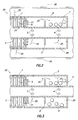
- FIG. 3 An alternate configuration of the apparatus 20 is representatively illustrated in FIG. 3 .
- One significant difference between the configurations of FIGS. 2 and 3 is that the configuration of FIG. 2 includes the presence of additional members 8 in the chamber 24, each of the members having a density approximately equal to that of water, or at least greater density than that of oil.
- the members 8 in the configuration of FIG. 3 preferably have a density of about 1030 kg/m 3 .
- the members 7 in the configuration of FIG. 3 preferably have a density of about 600 kg/m 3 to about 800 kg/m 3 .
- the density of the members 8 is preferably approximately the density of water, although the density of the members 8 may be between the density of water and the density of oil, if desired.
- the density of the members 7 is preferably between the density of oil and the density of gas.
- heavier members 8 provides the capability of increasingly restricting flow of the fluid 25, not only when excessive gas is produced along with oil, but also when excessive water is produced. Unlike the lower density members 7, the heavier members 8 are preferably not buoyant as long as the well is producing a sufficient proportion of oil. Instead, in this situation, the members 8 would preferably be positioned in a bottom portion of the chamber 24.
- FIGS. 4-8 depict other configurations of the apparatus 20. These embodiments are generally similar to the one discussed above and differ therefrom at least in part by having tubular flow restrictors 10, 11 providing flow passages between the interior of the housing 2 and the fluid outlets 4 and bypass outlets 3, respectively.
- the restrictors 10, 11 allow for larger internal passage dimensions than otherwise possible for the outlets 4, 3 while still maintaining desired pressure drops between the interior of the housing 2 and the interior of the tubular string 5.
- the housing 2 can include members 7 having a density between that of oil and gas or, alternatively, members 8, 7 having a density between that of oil and water (or approximately equal to water), and less than that of oil, respectively, as described above.
- Both the flow restrictors 10 and bypass restrictors 11 are preferably formed with a portion extending parallel to the tubular string 5, as depicted in FIGS. 4-6 . Ends of the flow restrictors 10 opposite the outlets 4 are secured to the excluder 6 in an appropriate manner.
- the members 7 are retained distant from the bypass restrictors 11 by the excluder 6.
- the excluder 6 is provided with seats 22 for engagement with the members 7. When a member 7 engages one of the seats 22, flow from the chamber 24 into the corresponding restrictor 10 is prevented, or at least is increasingly restricted.
- bypass restrictors 11 are longer than the flow restrictors 10. In this manner, flow through the bypass restrictors 11 is more restrictive compared to flow through the flow restrictors 10, so that less fluid is produced when the members 7, 8 prevent or increasingly restrict flow through the flow restrictors.
- each bypass restrictor 11 may be less than the flow area of each flow restrictor 10
- the total flow area of the bypass restrictors may be less than the total flow area of the flow restrictors (e.g., by providing fewer bypass restrictors than flow restrictors)
- the bypass restrictors may be provided with circuitous or tortuous flow paths, etc.
- any manner of increasingly restricting flow through the bypass restrictors 11 relative to flow through the flow restrictors 10 may be used in keeping with the principles of the invention.
- the bypass restrictors 11 may also be connected to the excluder 6, as depicted in FIGS. 7 and 8 .
- the inlets 23 to the bypass restrictors 11 have a shape preventing the members 7, 8 from completely blocking the bypass inlets.
- flow into the corresponding bypass restrictor 11 is preferably increasingly restricted.
- the fluid 25 enters the inlets of the restrictors 10, 11 in the same direction as the fluid flows into the chamber 24. In this manner, the fluid 25 applies both dynamic and static pressure to the inlets of the flow restrictors 10, 11. In contrast, in the configuration of FIG. 6 , the fluid 25 changes direction to enter the inlets of the restrictors 10, 11, and so the fluid applies substantially only static pressure on the inlets of the restrictors.
- the apparatus 20 in its various configurations described above is capable of achieving a variety of desirable benefits in different situations.
- the configurations of FIGS. 1-7 may be used (although the members 8 in FIGS. 3 and 5-8 may not be used), with the members 7 each having a density approximately equal to, or less than, that of water.
- the members 7 will either have neutral buoyancy in the water, or will float on top of the water, when the water enters the housing 2, and the members will thus be carried by the water to the outlets 4 or the seats 22 to thereby increasingly restrict or prevent flow of the water into the tubular string 5.
- FIGS. 2-8 when it is desired to limit the production of gas from an oil well (i.e., it is desired to produce oil, but not gas), the configurations of FIGS. 2-8 may again be used (although the members 8 in FIGS. 3 and 5-8 may not be used), with the members 7 each having a density less than that of oil. In this manner, the members 7 will float on top of the oil, or remain at the top of the housing 2 and away from the outlets 4 or the seats 22 as depicted in FIG. 4A , until a sufficient proportion of gas is produced to allow the members to descend in the housing and close off (or at least increasingly restrict) flow through the outlets. This will restrict or prevent flow of the gas into the tubular string 5.
- the members 7 are preferably not neutrally buoyant in the liquid phase (the oil), otherwise the members would be carried with the flow of the liquid to the outlets 4 or seats 22.
- the members 7 may be neutrally buoyant in the liquid phase (the water), since it is desired for the members to be carried with the flow of the liquid to the outlets 4 or seats 22 to restrict the flow of the liquid into the tubular string 5.
- the configurations of FIGS. 3 and 5-8 may be used, with the members 7 each having a density less than that of oil, and the members 8 each having a density greater than that of oil.
- the members 7 will preferably have densities between the densities of oil and gas, and the members 8 will preferably have densities between the densities of oil and water, or approximately equal to the density of water.
- the members 7 will float on top of the oil, or remain at the top of the housing 2 and away from the outlets 4 or the seats 22 as depicted in FIG. 4A , until a sufficient proportion of gas is produced to allow the members to descend in the housing and close off (or at least increasingly restrict) flow through the outlets. This will restrict or prevent flow of the gas into the tubular string 5.
- the members 8 will remain at the bottom of the housing 2 and away from the outlets 4 or the seats 22, until a sufficient proportion of water is produced to allow the members to ascend in the housing and close off (or at least increasingly restrict) flow through the outlets. This will restrict or prevent flow of the water into the tubular string 5.
- FIG. 9 Features of the apparatus 20 are schematically illustrated in FIG. 9 .
- the outlets 3, 4 are depicted in FIG. 9 as being vertically distributed and providing for communication between the chamber 24 (on the left of the illustration) and the interior of the tubular string 5 (on the right of the illustration).
- FIG. 9 schematically represents this vertical distribution of the outlets 3, 4, as well as the vertical distribution of the seats and inlets 22, 23 of the restrictors 10, 11.
- the fluid 25 is stratified in the chamber 24 into a layer of water 27, a layer of oil 28 and a layer of gas 29.
- Some of the members 7 are blocking (or at least increasingly restricting) flow of the gas 29 through the outlets 3, 4 into the tubular string 5, and some of the members 8 are blocking (or at least increasingly restricting) flow of the water 27 through the outlets into the tubular string.
- the members 7 preferably remain at the interface 31 between the gas 29 and the oil 28, since the members 7 are preferably less dense than the oil, but are not buoyant in the gas.
- the restrictors 10 are depicted in FIG. 9 as having larger internal passages as compared to the restrictors 11. In this manner, flow through the restrictors 11 is more restricted as compared to flow through the restrictors 10. When one of the members 7, 8 engages an inlet 23 of one of the restrictors 11, flow through the restrictor is increasingly restricted, but is not completely prevented.
- the fluid 25 could include mixtures of oil, water and/or gas in varying proportions.
- FIG. 10 the apparatus 20 is schematically illustrated in a configuration similar to that depicted in FIG. 9 .
- the upper portion of the chamber 24 has an increased proportion of gas 29 therein
- the lower portion of the chamber has an increased proportion of water 27 therein
- a middle portion of the chamber has an increased proportion of oil 28 therein.
- the water 27, oil 28 and gas 29 are not stratified, but are instead mixed in varying proportions.
- a less dense mixture of the fluid 25 e.g., having a relatively greater proportion of gas 29
- a more dense mixture of the fluid e.g., having a relatively greater proportion of water 27
- the most desirable mixture of the fluid e.g., having a relatively greater proportion of oil 28 than the other mixtures is between the other mixtures.
- the members 7 may be neutrally buoyant in the portion of the fluid 25 having the greater proportion of gas 29 therein. Thus, the members 7 do not necessarily remain at any particular interface between fluids.
- All of the members 7 do not necessarily have the same density, and all of the members 8 do not necessarily have the same density. Instead, the members 7 could have a range of different densities, and the members 8 could have a range of densities, so that the members are neutrally buoyant in different densities of the fluid 25. In this manner, a greater number of the members 8 would be available to block or restrict flow of the fluid 25 having a greater proportion of water, and a greater number of the members 7 would be available to block or restrict flow of the fluid having a greater proportion of gas.
- the configurations of the apparatus 20 including both of the members 7, 8 as illustrated in FIGS. 3 and 5-10 have the members positioned within a single internal chamber 24 of the housing 2.
- the members 7, 8 could instead be positioned in respective separate chambers, if desired.
- the members 7, 8 closing off or restricting flow through the same outlets 4, restrictors 10, seats 22, etc., separate outlets, restrictors and/or seats could be provided for the respective members, if desired.
Abstract
Description
- The present invention relates to equipment utilized and operations performed in conjunction with a subterranean well and, in embodiments described below, more particularly provides apparatus for automatically controlling inflow from a subterranean formation into a tubular string situated in the well.
- When the proportion of formation water and/or gas produced from a well becomes excessive, production has to be stopped in many cases. Breakthrough of water or gas can vary along the well from one zone to another, and is dependent on the reservoir permeability, pressure communication in the reservoir, coning and other inhomogeneities in the reservoir. However, shut-in of a zone mainly producing water can result in increased production from other zones in the well which mainly produce oil.
- In recent years this knowledge has lead to the development of systems comprising surface controlled valves and adjustable nozzles. Some of the disadvantages associated with such systems are technical complexity and the necessity of complicated downhole equipment, thereby resulting in poor reliability. Another disadvantage is that such systems typically constrict the flow area of tubing situated in the well.
- Certain well installations benefit from having a flow restriction device in a well screen. For example, such flow restriction devices have been useful in preventing water coning, balancing production from long horizontal intervals, etc. These flow restriction devices are sometimes referred to as "inflow control devices."
- In certain proposed inflow control devices, the devices are adapted to counter frictional effects caused by the flow of fluid through the tubing. However, these devices do not have the ability to regulate the pressure drop across the system based on water cut in the fluid. Before flowing into the tubing, the produced fluids have to flow through a fixed flow restriction, such as a capillary tube or nozzle, typically arranged around the tubing in the form of a helical thread. The fluid flows through grooves of the thread.
- Another proposed inflow control device is used when gas is desired to be produced from a well without simultaneous production of water. The device is equipped with spherical, stacked controlled buoyancy elements, each of which has a density less than water. Upon ingress of water from the formation, the elements become buoyant and close one or more openings, so as to prevent water from flowing into the tubing.
- Yet another proposed inflow control device includes a flow chamber secured to the tubing and provided with floating bodies, each having a density approximately equal to that of formation water. The chamber is formed with an inlet and surrounds nozzles providing fluid communication between the tubing and the formation. When the inflow includes a sufficient proportion of water, the floating bodies become buoyant and float from a position within the chamber distant from the nozzles to a position closing or covering the nozzles, thereby restricting the inflow into the tubing.
- From the foregoing, it is apparent that improvements are needed in the art of automatic inflow control in wells. The improvements may be useful in other operations, as well.
- In carrying out the principles of the present invention, an apparatus is provided which solves at least one problem in the art. An example is described below in which the flow of gas, or alternating water or gas, along with produced oil is restricted. Another example is provided in which features are included to prevent outlets in the apparatus from being plugged and the like.
- According to one described embodiment, there is provided an apparatus for restricting the flow of undesired fluids from a subterranean formation into a tubular string situated in a hydrocarbon producing well. The apparatus includes a flow housing secured to the tubular string and adapted to surround outlets communicating the tubular string with the formation via the housing. The housing has an inlet for the fluid and is provided with flow blocking members which, when the fluid does not mainly include oil, are adapted to float from a position within the housing distant from the outlets to a position closing, covering or otherwise increasingly restricting flow through the outlets.
- Preferably, the flow blocking members are in the form of balls. If the undesired fluid is gas, then preferably the members have a density less than oil, so as to increasingly shut off or choke the flow into the tubular string when an increased proportion of gas is produced.
- If the undesired fluid is water, then preferably the members have a density approximately equal to the water. Alternatively, the members may have a density less than that of the water, or greater than that of oil or gas (whichever of these is desired to be produced and has the greatest density). As another alternative, some of the members may have a density approximately equal to that of the water, and some of the members may have a density less than that of the water.
- The outlets are preferably provided with restrictors. Some of the restrictors may have greater flow restriction therethrough than others of the restrictors. Some of the restrictors may be used to bypass the effect of the flow blocking members, so that the flow blocking members have no effect on flow through these restrictors. Alternatively, the flow blocking members may engage and increasingly restrict flow through the restrictors, without entirely preventing flow through the restrictors.
- When producing undesired gas along with desired oil, it is possible to restrict the flow of the gas by using a flow blocking member density lighter than the produced oil, preferably from about 600 kg/m3 to about 800 kg/m3. Similarly, in case of unwanted amounts of produced water or gas, the flow of water can be increasingly restricted by addition of flow blocking members having a density equal to the formation water density, normally approximately 1030 kg/m3. Upon production of water, the members may become neutrally buoyant and able to increasingly restrict flow through the outlets due to drag caused by flow through the outlets.
- By using tubular extensions for the outlets, a desired pressure drop can be maintained, while allowing for a larger diameter internal passage, as compared to a simple nozzle. Bypass outlets, or restrictors not being closed by the members, allow for some flow of oil and gas or water into the tubular string, thereby not completely stopping the production even at a high level of gas or water cut.
- To reduce the flow from various zones of the formation potentially producing an excessively large proportion of gas or water, more than one apparatus can be disposed at relatively short intervals along the tubular string. Since these apparatuses operate independently of each other and with immediate response, greater selectivity and better control is achieved.
- Thus, an apparatus is provided for use in a well wherein fluid is produced which includes both oil and gas. The apparatus includes multiple flow blocking members, each of the members having a density less than that of the oil. The members are positioned within a chamber so that the members increasingly restrict a flow of the gas out of the chamber through multiple outlets.
- Also provided is an apparatus for restricting production of at least one undesired fluid from a well, the undesired fluid having a density different from a density of a desired fluid. The apparatus includes at least one flow restrictor and at least one bypass flow restrictor. The bypass restrictor may have a greater restriction to flow therethrough as compared to the other flow restrictor.
- The apparatus further includes multiple flow blocking members. The members are operative to increasingly restrict flow of the undesired fluid through the flow restrictor in response to an increased proportion of the undesired fluid.
- These and other features, advantages, benefits and objects of the present invention will become apparent to one of ordinary skill in the art upon careful consideration of the detailed description of representative embodiments of the invention hereinbelow and the accompanying drawings, in which similar elements are indicated in the various figures using the same reference numbers.
-
-
FIG. 1 is a schematic partially cross-sectional view of a well system embodying principles of the present invention; -
FIG. 2 is a schematic cross-sectional view of an apparatus embodying principles of the invention which may be used in the well system ofFIG. 1 , the apparatus including a flow housing and flow blocking members in the form of balls having a density less than oil; -
FIG. 3 is a schematic cross-sectional view of an alternate configuration of the apparatus, wherein balls having an increased density are included; -
FIG. 4 is a schematic cross-sectional view of another alternate configuration of the apparatus, including tubular restrictor extensions of fluid outlets and bypass outlets, respectively; -
FIG. 4A is a cross-sectional view of the apparatus, taken alongline 4A-4A ofFIG. 4 ; -
FIG. 5 is a schematic cross-sectional view of another alternate configuration of the apparatus, similar to the configuration ofFIG. 3 , but including tubular restrictor extensions of the fluid outlets and bypass outlets, respectively; -
FIG. 6 is a schematic cut-way view in perspective of another alternate configuration of the apparatus; -
FIG. 7 is a schematic cut-way view of another alternate embodiment of the apparatus, wherein both the fluid restrictors and bypass restrictors are connected between outlets and a excluder; -
FIG. 8 is a schematic fragmentary perspective view illustrating different inlet shapes of the fluid restrictors and bypass restrictors in the configuration ofFIG. 7 ; -
FIG. 9 is a schematic cross-sectional view of the apparatus with separate stratified layers of gas, oil and water in a chamber of the apparatus; and -
FIG. 10 is a schematic cross-sectional view of the apparatus with mixtures of different proportions of gas, oil and water in the chamber. - It is to be understood that the various embodiments of the present invention described herein may be utilized in various orientations, such as inclined, inverted, horizontal, vertical, etc., and in various configurations, without departing from the principles of the present invention. The embodiments are described merely as examples of useful applications of the principles of the invention, which is not limited to any specific details of these embodiments.
- In the following description of the representative embodiments of the invention, directional terms, such as "above", "below", "upper", "lower", etc., are used for convenience in referring to the accompanying drawings.
- The embodiments described below each include an apparatus which automatically controls the flow from a subterranean formation into a tubular string situated in a hydrocarbon producing well. Although the drawings illustrate a tubular string oriented in a horizontal direction, it is to be understood that the invention is applicable to tubular strings orientated in the vertical direction, as well as any other direction. The formation from which fluid is produced may be found either offshore or onshore.
- Representatively illustrated in
FIG. 1 is awell system 40 which embodies principles of the present invention. A tubular string 5 (such as a production tubing string) is installed in awellbore 41 of a well. Thetubular string 5 includes multiplewell screens 1 positioned in an uncased generally horizontal portion of thewellbore 41. - One or more of the well screens 1 may be positioned in an isolated portion of the
wellbore 41, for example, betweenpackers 42 set in the wellbore. In addition, or alternatively, many of the well screens 1 could be positioned in a long, continuous portion of thewellbore 41, without packers isolating the wellbore between the screens. - Gravel packs could be provided about any or all of the well screens 1, if desired. A variety of additional well equipment (such as valves, sensors, pumps, control and actuation devices, etc.) could also be provided in the
well system 40. - It should be clearly understood that the
well system 40 is merely representative of one well system in which the principles of the invention may be beneficially utilized. However, the invention is not limited in any manner to the details of thewell system 40 described herein. For example, thescreens 1 could instead be positioned in a cased and perforated portion of a wellbore, the screens could be positioned in a generally vertical portion of a wellbore, the screens could be used in an injection well, rather than in a production well, etc. - As described more fully below, the
screens 1 are each part of anapparatus 20 which includes an inflow control device. However, it should be clearly understood that it is not necessary for theapparatus 20 to include ascreen 1, since an inflow control device can be used apart from a screen, if desired. - Each
apparatus 20 is operative to variably restrict flow from an adjacent zone into thetubular string 5. When the zone corresponding to a particular one of theapparatuses 20 produces a greater proportion of an undesired fluid (such as water, or sometimes gas), the apparatus will increasingly restrict flow from that zone. Thus, the other zones which are producing a greater proportion of desired fluid (such as oil) will contribute more to the production via thetubular string 5. In particular, there will be a greater pressure drop from the formation to thetubular string 5, resulting in a greater production of desired fluid, due to the increased restriction to flow from the zones which produce greater proportions of undesired fluid. - As representatively illustrated in
FIG. 2 , theapparatus 20 includes aflow housing 2 secured to thetubular string 5, e.g., with the housing secured to a pipe interconnected as a part of the tubular string.Outlets 4 provide fluid communication between aninterior chamber 24 of thehousing 2 and an interior of thetubular string 5. - Oil to be produced from a formation is able to flow into the
tubular string 5 at a rate partly determined by the number ofoutlets 4, and the length and flow areas thereof. Theoutlets 4 may, for example, be in the form of nozzles or other types of flow restrictors. - An
inlet 21 is formed at an end of thehousing 2 for receivingfluid 25 from asubterranean formation 26. To prevent plugging due to presence of particles and other debris in theformation fluid 25, theinlet 21 may be provided with asuitable filter 9. - A
screen 1 of appropriate kind can be placed upstream of theinlet 21. Alternatively, thehousing 2 could be positioned upstream of thescreen 1, if desired. Thescreen 1 is not necessary in keeping with the principles of the invention. - One or more
flow blocking members 7 in the form of balls are present within thehousing 2 to restrict flow of undesired portions of the fluid 25 via theoutlets 4, for example, when the oil produced includes undesirable quantities of gas. In that situation, the density of each of themembers 7 is preferably less than that of the oil, enabling each to either maintain a position within thehousing 2 distant from the outlets 4 (when only a very small proportion of gas is present in the chamber 24), or a position (not shown) shutting off or choking flow through the outlets (when a larger proportion of gas is present in the chamber). - Thus, when the fluid 25 is mainly oil, the
members 7 will be positioned relatively distant from theoutlets 4, for example, at the top of thechamber 24. However, when a sufficient proportion of gas also is present in the fluid 25, themembers 7 will restrict flow of the gas by shutting off or choking flow through certain ones of theoutlets 4. - It should be understood that, although the
members 7 are depicted in the drawings and described herein as being in the form of balls, other shapes (such as cylindrical, prismatic, etc.) may be used in keeping with the principles of the invention. It also is not necessary for aparticular member 7 to completely block flow through arespective outlet 4, since the member could instead merely increasingly restrict flow through the outlet, if desired. - By selecting an average density preferably from about 600 kg/m3 to about 800 kg/m3, and by keeping in mind that the density of oil is typically somewhat less than 900 kg/m3, the
members 7 will be in a buoyant or "free-floating" state as long as the gas potentially included in the fluid does not lower the overall density of the fluid 25 below the selected member density. On the other hand, if the influx of gas should result in an overall density of the fluid approximately equal to the member density, then themembers 7 will have "neutral buoyancy" and will be dragged to theoutlets 4 due to the pressure drop over these. Therespective outlet 4 can be blocked by means of asingle member 7 or, alternatively, can be blocked by means of several members. - The density of the
members 7 is preferably between the density of oil and the density of gas. If the oil and gas are separated in the chamber 24 (i.e., with the lower density gas above the higher density oil), then themembers 7 will be positioned at the interface between the oil and gas. - As the interface descends in the chamber 24 (i.e., there is an increasing proportion of gas in the chamber), an increasing number of the
outlets 4 will be blocked by themembers 7. As the interface ascends in the chamber 24 (i.e., there is an increasing proportion of oil in the chamber), a decreasing number of theoutlets 4 will be blocked by themembers 7. - Thus, the
apparatus 20 provides multiple benefits. As the proportion of gas increases, the restriction to flow of the fluid 25 through thehousing 2 also increases. Furthermore, themembers 7 block theoutlets 4 which are more exposed to the gas in thechamber 24, thereby providing a larger pressure drop across the apparatus, increasing the pressure drop across other zones in the well, allowing greater production from oil producing zones, and thereby allowing a greater production of oil from other zones to flow into thetubular string 5. - There might be instances in which a complete closedown of production is undesirable, no matter how great the proportion of gas in the
fluid 25.Optional bypass outlets 3 can be used to provide communication between the interior of thehousing 2 and the interior of thetubular string 5, thereby allowing for some production, even though themembers 7 may have shut off or choked flow through the remaining outlets 4 (such as, in case of large gas quantities in the fluid 25). - The
bypass outlets 3 may, for example, be in the form of nozzles or other types of flow restrictors. Preferably, theoutlets 3 have greater restriction to flow therethrough as compared to theoutlets 4, for example, so that if the fluid 25 contains a large proportion of gas, only very limited flow through theoutlets 3 will be permitted. - The
members 7 are retained distant from thebypass outlets 3 by means of anexcluder 6 in the form of a spacer ring secured to thetubular string 5 and having a height to prevent passage of themembers 7 to the bypass outlets. Other types of excluders (such as screens, traps, etc.) may be used in keeping with the principles of the invention. - To prevent an excessive quantity of gas from being produced from multiple zones, the fluid 25 from different zones can be individually restricted by disposing more than one
apparatus 20 along thetubular string 5. One ormore apparatus 20 can be used to control the flow of fluid from each corresponding zone. As a result, the well will produce an increased proportion of oil, due to the fact that the zones producing excessive amounts of gas are shut off or increasingly choked by thecorresponding apparatus 20. - An alternate configuration of the
apparatus 20 is representatively illustrated inFIG. 3 . One significant difference between the configurations ofFIGS. 2 and 3 is that the configuration ofFIG. 2 includes the presence ofadditional members 8 in thechamber 24, each of the members having a density approximately equal to that of water, or at least greater density than that of oil. - The
members 8 in the configuration ofFIG. 3 preferably have a density of about 1030 kg/m3. Themembers 7 in the configuration ofFIG. 3 preferably have a density of about 600 kg/m3 to about 800 kg/m3. The density of themembers 8 is preferably approximately the density of water, although the density of themembers 8 may be between the density of water and the density of oil, if desired. The density of themembers 7 is preferably between the density of oil and the density of gas. - The addition of such
heavier members 8 provides the capability of increasingly restricting flow of the fluid 25, not only when excessive gas is produced along with oil, but also when excessive water is produced. Unlike thelower density members 7, theheavier members 8 are preferably not buoyant as long as the well is producing a sufficient proportion of oil. Instead, in this situation, themembers 8 would preferably be positioned in a bottom portion of thechamber 24. - "Neutral buoyancy" of the
members 8 only occurs when a sufficient proportion of water is produced to cause a sufficiently increased proportion of water in the producedfluid 25. When the density of the fluid 25 increases by a sufficient amount, theheavier members 8 become neutrally buoyant and are carried by the water phase and engage theoutlets 4, due to the pressure drop across the outlets, thereby restricting flow of the fluid into thetubular string 5. - There might be some concerns as to plugging, etc. of
fluid outlets 4 andbypass outlets 3 if they have very small internal diameters. To prevent such problems,FIGS. 4-8 depict other configurations of theapparatus 20. These embodiments are generally similar to the one discussed above and differ therefrom at least in part by havingtubular flow restrictors housing 2 and thefluid outlets 4 andbypass outlets 3, respectively. - The
restrictors outlets housing 2 and the interior of thetubular string 5. Thehousing 2 can includemembers 7 having a density between that of oil and gas or, alternatively,members - Both the
flow restrictors 10 andbypass restrictors 11 are preferably formed with a portion extending parallel to thetubular string 5, as depicted inFIGS. 4-6 . Ends of theflow restrictors 10 opposite theoutlets 4 are secured to theexcluder 6 in an appropriate manner. - The
members 7 are retained distant from thebypass restrictors 11 by theexcluder 6. In addition, theexcluder 6 is provided withseats 22 for engagement with themembers 7. When amember 7 engages one of theseats 22, flow from thechamber 24 into the correspondingrestrictor 10 is prevented, or at least is increasingly restricted. - As depicted in the configuration of
FIG. 7 , thebypass restrictors 11 are longer than theflow restrictors 10. In this manner, flow through thebypass restrictors 11 is more restrictive compared to flow through theflow restrictors 10, so that less fluid is produced when themembers - Other methods may be used to provide increased restriction to flow through the
bypass restrictors 11. For example, the flow area of eachbypass restrictor 11 may be less than the flow area of each flow restrictor 10, the total flow area of the bypass restrictors may be less than the total flow area of the flow restrictors (e.g., by providing fewer bypass restrictors than flow restrictors), the bypass restrictors may be provided with circuitous or tortuous flow paths, etc. Thus, any manner of increasingly restricting flow through thebypass restrictors 11 relative to flow through theflow restrictors 10 may be used in keeping with the principles of the invention. - To reduce the height of the
housing 2, thebypass restrictors 11 may also be connected to theexcluder 6, as depicted inFIGS. 7 and8 . In this configuration, theinlets 23 to thebypass restrictors 11 have a shape preventing themembers members inlets 23, flow into thecorresponding bypass restrictor 11 is preferably increasingly restricted. - Note that, in the configuration of
FIGS. 7 and8 , the fluid 25 enters the inlets of therestrictors chamber 24. In this manner, the fluid 25 applies both dynamic and static pressure to the inlets of theflow restrictors FIG. 6 , the fluid 25 changes direction to enter the inlets of therestrictors - It may now be fully appreciated that the
apparatus 20 in its various configurations described above is capable of achieving a variety of desirable benefits in different situations. For example, when it is desired to limit the production of water from a gas well (i.e., it is desired to produce gas, but not water), the configurations ofFIGS. 1-7 may be used (although themembers 8 inFIGS. 3 and5-8 may not be used), with themembers 7 each having a density approximately equal to, or less than, that of water. In this manner, themembers 7 will either have neutral buoyancy in the water, or will float on top of the water, when the water enters thehousing 2, and the members will thus be carried by the water to theoutlets 4 or theseats 22 to thereby increasingly restrict or prevent flow of the water into thetubular string 5. - As another example, when it is desired to limit the production of gas from an oil well (i.e., it is desired to produce oil, but not gas), the configurations of
FIGS. 2-8 may again be used (although themembers 8 inFIGS. 3 and5-8 may not be used), with themembers 7 each having a density less than that of oil. In this manner, themembers 7 will float on top of the oil, or remain at the top of thehousing 2 and away from theoutlets 4 or theseats 22 as depicted inFIG. 4A , until a sufficient proportion of gas is produced to allow the members to descend in the housing and close off (or at least increasingly restrict) flow through the outlets. This will restrict or prevent flow of the gas into thetubular string 5. - Note that the case of restricting production of gas from an oil well is quite different from the case of restricting production of water from a gas well. When restricting the production of gas from an oil well, the
members 7 are preferably not neutrally buoyant in the liquid phase (the oil), otherwise the members would be carried with the flow of the liquid to theoutlets 4 or seats 22. When restricting the production of water from a gas well, themembers 7 may be neutrally buoyant in the liquid phase (the water), since it is desired for the members to be carried with the flow of the liquid to theoutlets 4 orseats 22 to restrict the flow of the liquid into thetubular string 5. - As yet another example, when it is desired to limit the production of gas and water from an oil well (i.e., it is desired to produce oil, but not gas or water), the configurations of
FIGS. 3 and5-8 may be used, with themembers 7 each having a density less than that of oil, and themembers 8 each having a density greater than that of oil. Themembers 7 will preferably have densities between the densities of oil and gas, and themembers 8 will preferably have densities between the densities of oil and water, or approximately equal to the density of water. - In this manner, the
members 7 will float on top of the oil, or remain at the top of thehousing 2 and away from theoutlets 4 or theseats 22 as depicted inFIG. 4A , until a sufficient proportion of gas is produced to allow the members to descend in the housing and close off (or at least increasingly restrict) flow through the outlets. This will restrict or prevent flow of the gas into thetubular string 5. - The
members 8 will remain at the bottom of thehousing 2 and away from theoutlets 4 or theseats 22, until a sufficient proportion of water is produced to allow the members to ascend in the housing and close off (or at least increasingly restrict) flow through the outlets. This will restrict or prevent flow of the water into thetubular string 5. - Features of the
apparatus 20 are schematically illustrated inFIG. 9 . Theoutlets FIG. 9 as being vertically distributed and providing for communication between the chamber 24 (on the left of the illustration) and the interior of the tubular string 5 (on the right of the illustration). - Of course, in the
apparatus 20 as shown in the previousFIGS. 2-8 , theoutlets FIG. 9 , but it will be appreciated that, due to the outlets being formed radially about thetubular string 5, some of the outlets are vertically higher, and some of the outlets are vertically lower, relative to others of the outlets. Thus,FIG. 9 schematically represents this vertical distribution of theoutlets inlets restrictors - In this example, the fluid 25 is stratified in the
chamber 24 into a layer ofwater 27, a layer ofoil 28 and a layer ofgas 29. Some of themembers 7 are blocking (or at least increasingly restricting) flow of thegas 29 through theoutlets tubular string 5, and some of themembers 8 are blocking (or at least increasingly restricting) flow of thewater 27 through the outlets into the tubular string. - Thus, as the fluid 25 contains a greater proportion of
gas 29 and/orwater 27, flow through theapparatus 20 is increasingly restricted. An increased proportion ofoil 28 in the fluid 25, however, results in a reduced restriction to flow through theapparatus 20, since fewer of the outlets will be blocked by themembers - As an
interface 30 between thewater 27 andoil 28 ascends in thechamber 24, more of themembers 8 block (or at least increasingly restrict) flow of the water through therestrictors interface 30 descends in thechamber 24, themembers 8 can disengage from the seats andinlets oil 28 to flow through therestrictors outlets tubular string 5. - As an
interface 31 between thegas 29 and theoil 28 descends in thechamber 24, more of themembers 7 block (or at least increasingly restrict) flow of the gas through therestrictors interface 31 ascends in thechamber 24, themembers 7 can disengage from the seats andinlets oil 28 to flow through therestrictors outlets tubular string 5. - Note that the
members 7 preferably remain at theinterface 31 between thegas 29 and theoil 28, since themembers 7 are preferably less dense than the oil, but are not buoyant in the gas. Themembers 8, however, may remain at theinterface 30 between theoil 28 and the water 27 (for example, if themembers 8 are less dense than the water, but more dense than the oil), or themembers 8 may be neutrally buoyant in the water (for example, if the members have approximately the same density as the water). - The
restrictors 10 are depicted inFIG. 9 as having larger internal passages as compared to therestrictors 11. In this manner, flow through therestrictors 11 is more restricted as compared to flow through therestrictors 10. When one of themembers inlet 23 of one of therestrictors 11, flow through the restrictor is increasingly restricted, but is not completely prevented. - Thus, in the example of
FIG. 9 , some of thegas 29 is permitted to flow through theupper restrictors 11 which are engaged by themembers 7, and some of thewater 27 is permitted to flow through the lower restrictors which are engaged by themembers 8, but these flows are very restricted. This increased restriction to flow is due to the engagement between themembers respective inlets 23, and to the increased restriction to flow through therestrictors 11. - As depicted in
FIG. 9 , engagement between themembers seats 22 completely prevents flow through the correspondingrestrictors 10. However, such engagement could permit an increased restriction to flow, without completely preventing flow, if desired. - Note that it is not necessary for the fluid 25 to be stratified into separate fluid layers as illustrated in
FIG. 9 . Instead, the fluid 25 could include mixtures of oil, water and/or gas in varying proportions. - In
FIG. 10 theapparatus 20 is schematically illustrated in a configuration similar to that depicted inFIG. 9 . However, in the configuration ofFIG. 10 , the upper portion of thechamber 24 has an increased proportion ofgas 29 therein, the lower portion of the chamber has an increased proportion ofwater 27 therein, and a middle portion of the chamber has an increased proportion ofoil 28 therein. - Unlike the configuration of
FIG. 9 , thewater 27,oil 28 andgas 29 are not stratified, but are instead mixed in varying proportions. A less dense mixture of the fluid 25 (e.g., having a relatively greater proportion of gas 29) ascends to the top of thechamber 24, a more dense mixture of the fluid (e.g., having a relatively greater proportion of water 27) descends to the bottom of the chamber, and the most desirable mixture of the fluid (e.g., having a relatively greater proportion ofoil 28 than the other mixtures) is between the other mixtures. - Thus, when the fluid 25 contains undesirable fluids (for example, water or sometimes gas), restriction to flow through the
apparatus 20 increases. A greater proportion of undesirable fluids in the producedfluid 25 results in a greater restriction to flow through theapparatus 20. Thus, production from a zone producing undesirable fluids is reduced (due to the increased restriction to flow through its corresponding apparatus 20), while production from other zones producing more desirable fluids is increased. - Note that, in the configuration of
FIG. 10 , themembers 7 may be neutrally buoyant in the portion of the fluid 25 having the greater proportion ofgas 29 therein. Thus, themembers 7 do not necessarily remain at any particular interface between fluids. - All of the
members 7 do not necessarily have the same density, and all of themembers 8 do not necessarily have the same density. Instead, themembers 7 could have a range of different densities, and themembers 8 could have a range of densities, so that the members are neutrally buoyant in different densities of the fluid 25. In this manner, a greater number of themembers 8 would be available to block or restrict flow of the fluid 25 having a greater proportion of water, and a greater number of themembers 7 would be available to block or restrict flow of the fluid having a greater proportion of gas. - The configurations of the
apparatus 20 including both of themembers FIGS. 3 and5-10 have the members positioned within a singleinternal chamber 24 of thehousing 2. However, themembers members same outlets 4,restrictors 10,seats 22, etc., separate outlets, restrictors and/or seats could be provided for the respective members, if desired. - Of course, a person skilled in the art would, upon a careful consideration of the above description of representative embodiments of the invention, readily appreciate that many modifications, additions, substitutions, deletions, and other changes may be made to these specific embodiments, and such changes are within the scope of the principles of the present invention. Accordingly, the foregoing detailed description is to be clearly understood as being given by way of illustration and example only, the spirit and scope of the present invention being limited solely by the appended claims and their equivalents.
Claims (32)
- An apparatus for restricting production of at least a first undesired fluid from a subterranean well, the first fluid having a first density different from a second density of a second desired fluid, the apparatus comprising:at least one first flow restrictor having a first flow restriction;at least one second flow restrictor having a second flow restriction; andmultiple first flow blocking members, the first members being operative to increasingly restrict flow of the first fluid through the first restrictor in response to an increased proportion of the first fluid.
- The apparatus of claim 1, wherein the apparatus includes multiple first flow restrictors, and wherein passages of the first restrictors are vertically distributed.
- The apparatus of claim 1, wherein the second flow restriction is greater than the first flow restriction.
- The apparatus of claim 1, wherein the first members increasingly restrict, but do not prevent, flow of the first fluid through the second restrictors.
- The apparatus of claim 1, wherein the second restrictors have inlets which prevent complete flow blocking engagement between the first members and the inlets.
- The apparatus of claim 1, wherein the first members have a density less than the second density of the second fluid.
- The apparatus of claim 1, wherein the first members have a density less than the first density of the first fluid.
- The apparatus of claim 1, wherein the first members have a density approximately equal to the first density of the first fluid.
- The apparatus of claim 1, wherein a third undesired fluid has a third density different from the first and second densities, and wherein the apparatus further comprises multiple second flow blocking members, the second members being operative to increasingly restrict flow of the third fluid through the first restrictor in response to an increased proportion of the third fluid.
- The apparatus of claim 9, wherein the apparatus includes multiple first flow restrictors, and wherein passages of the first restrictors are vertically distributed.
- The apparatus of claim 9, wherein the second flow restriction is greater than the first flow restriction.
- The apparatus of claim 9, wherein the second members increasingly restrict, but do not prevent, flow of the third fluid through the second restrictors.
- The apparatus of claim 9, wherein the second restrictors have inlets which prevent complete flow blocking engagement between the second members and the inlets.
- The apparatus of claim 9, wherein the second members have a density less than the third density of the third fluid.
- The apparatus of claim 9, wherein the second members have a density greater than the second density of the second fluid.
- The apparatus of claim 9, wherein the second members have a density approximately equal to the third density of the third fluid.
- An apparatus for use in a subterranean well wherein fluid is produced which includes both oil and gas, the apparatus comprising:multiple first flow blocking members, each of the first members having a density less than that of the oil, and the first members being positioned within a chamber so that the first members increasingly restrict a flow of the gas out of the chamber through multiple first outlets.
- The apparatus of claim 17, wherein passages between the chamber and the first outlets are vertically distributed.
- The apparatus of claim 18, wherein at least one of the passages is provided with an inlet which permits at least limited flow of the gas through the corresponding passage when one of the first members is engaged with the inlet.
- The apparatus of claim 18, wherein a first portion of the passages has greater flow restriction than a second portion of the passages.
- The apparatus of claim 20, wherein the first members do not increasingly restrict flow through the first portion of the passages in response to an increased proportion of gas in the chamber.
- The apparatus of claim 20, wherein the first members increasingly restrict, but do not prevent, flow through the first portion of the passages in response to an increased proportion of gas in the chamber.
- The apparatus of claim 17, wherein the first members increasingly restrict flow of the gas through an increased number of the first outlets in response to an increased proportion of the gas in the chamber.
- The apparatus of claim 17, wherein the produced fluid also includes water, and wherein the apparatus further comprises multiple second flow blocking members, each of the second members having a density greater than that of the oil, so that the second members increasingly restrict a flow of the water outward through multiple second outlets.
- The apparatus of claim 24, wherein the second members are positioned in the same chamber as the first members.
- The apparatus of claim 24, wherein the first and second members are not positioned in the same chamber.
- The apparatus of claim 24, wherein passages for flow to the second outlets are vertically distributed.
- The apparatus of claim 27, wherein at least one of the passages is provided with an inlet which permits at least limited flow of the water through the corresponding passage when one of the second members is engaged with the inlet.
- The apparatus of claim 27, wherein a first portion of the passages has greater flow restriction than a second portion of the passages.
- The apparatus of claim 29, wherein the second members do not increasingly restrict flow through the first portion of the passages in response to an increased proportion of water.
- The apparatus of claim 29, wherein the second members increasingly restrict, but do not prevent, flow through the first portion of the passages in response to an increased proportion of water.
- The apparatus of claim 24, wherein the second members increasingly restrict flow of the water through an increased number of the second outlets in response to an increased proportion of the water.
Applications Claiming Priority (2)
| Application Number | Priority Date | Filing Date | Title |
|---|---|---|---|
| US11/466,022 US20080041580A1 (en) | 2006-08-21 | 2006-08-21 | Autonomous inflow restrictors for use in a subterranean well |
| EP07814000A EP2052128A2 (en) | 2006-08-21 | 2007-08-10 | Autonomous inflow restrictors for use in a subterranean well |
Related Parent Applications (1)
| Application Number | Title | Priority Date | Filing Date |
|---|---|---|---|
| EP07814000A Division EP2052128A2 (en) | 2006-08-21 | 2007-08-10 | Autonomous inflow restrictors for use in a subterranean well |
Publications (1)
| Publication Number | Publication Date |
|---|---|
| EP2146049A2 true EP2146049A2 (en) | 2010-01-20 |
Family
ID=39100277
Family Applications (2)
| Application Number | Title | Priority Date | Filing Date |
|---|---|---|---|
| EP07814000A Withdrawn EP2052128A2 (en) | 2006-08-21 | 2007-08-10 | Autonomous inflow restrictors for use in a subterranean well |
| EP09160228A Withdrawn EP2146049A2 (en) | 2006-08-21 | 2007-08-10 | Autonomous inflow restrictors for use in a subterranean well |
Family Applications Before (1)
| Application Number | Title | Priority Date | Filing Date |
|---|---|---|---|
| EP07814000A Withdrawn EP2052128A2 (en) | 2006-08-21 | 2007-08-10 | Autonomous inflow restrictors for use in a subterranean well |
Country Status (7)
| Country | Link |
|---|---|
| US (1) | US20080041580A1 (en) |
| EP (2) | EP2052128A2 (en) |
| AU (1) | AU2007286918A1 (en) |
| BR (1) | BRPI0715720A2 (en) |
| MX (1) | MX2009001906A (en) |
| NO (1) | NO20091161L (en) |
| WO (1) | WO2008024645A2 (en) |
Cited By (13)
| Publication number | Priority date | Publication date | Assignee | Title |
|---|---|---|---|---|
| WO2012036917A3 (en) * | 2010-09-14 | 2012-06-07 | Halliburton Energy Services, Inc. | Self-releasing plug for use in a subterranean well |
| US8235128B2 (en) | 2009-08-18 | 2012-08-07 | Halliburton Energy Services, Inc. | Flow path control based on fluid characteristics to thereby variably resist flow in a subterranean well |
| US8261839B2 (en) | 2010-06-02 | 2012-09-11 | Halliburton Energy Services, Inc. | Variable flow resistance system for use in a subterranean well |
| US8276669B2 (en) | 2010-06-02 | 2012-10-02 | Halliburton Energy Services, Inc. | Variable flow resistance system with circulation inducing structure therein to variably resist flow in a subterranean well |
| US8356668B2 (en) | 2010-08-27 | 2013-01-22 | Halliburton Energy Services, Inc. | Variable flow restrictor for use in a subterranean well |
| US8430130B2 (en) | 2010-09-10 | 2013-04-30 | Halliburton Energy Services, Inc. | Series configured variable flow restrictors for use in a subterranean well |
| US8678035B2 (en) | 2011-04-11 | 2014-03-25 | Halliburton Energy Services, Inc. | Selectively variable flow restrictor for use in a subterranean well |
| US8684094B2 (en) | 2011-11-14 | 2014-04-01 | Halliburton Energy Services, Inc. | Preventing flow of undesired fluid through a variable flow resistance system in a well |
| US8893804B2 (en) | 2009-08-18 | 2014-11-25 | Halliburton Energy Services, Inc. | Alternating flow resistance increases and decreases for propagating pressure pulses in a subterranean well |
| US8950502B2 (en) | 2010-09-10 | 2015-02-10 | Halliburton Energy Services, Inc. | Series configured variable flow restrictors for use in a subterranean well |
| US8967267B2 (en) | 2011-11-07 | 2015-03-03 | Halliburton Energy Services, Inc. | Fluid discrimination for use with a subterranean well |
| US9506320B2 (en) | 2011-11-07 | 2016-11-29 | Halliburton Energy Services, Inc. | Variable flow resistance for use with a subterranean well |
| RU218391U1 (en) * | 2023-02-21 | 2023-05-24 | федеральное государственное бюджетное образовательное учреждение высшего образования "Санкт-Петербургский горный университет" | GAS INFLOW CONTROL DEVICE |
Families Citing this family (66)
| Publication number | Priority date | Publication date | Assignee | Title |
|---|---|---|---|---|
| AU2007243920B2 (en) * | 2006-04-03 | 2012-06-14 | Exxonmobil Upstream Research Company | Wellbore method and apparatus for sand and inflow control during well operations |
| US8453746B2 (en) * | 2006-04-20 | 2013-06-04 | Halliburton Energy Services, Inc. | Well tools with actuators utilizing swellable materials |
| US7708068B2 (en) * | 2006-04-20 | 2010-05-04 | Halliburton Energy Services, Inc. | Gravel packing screen with inflow control device and bypass |
| US20080041588A1 (en) * | 2006-08-21 | 2008-02-21 | Richards William M | Inflow Control Device with Fluid Loss and Gas Production Controls |
| US20080041582A1 (en) * | 2006-08-21 | 2008-02-21 | Geirmund Saetre | Apparatus for controlling the inflow of production fluids from a subterranean well |
| US7832473B2 (en) * | 2007-01-15 | 2010-11-16 | Schlumberger Technology Corporation | Method for controlling the flow of fluid between a downhole formation and a base pipe |
| BRPI0721215B1 (en) | 2007-02-06 | 2018-05-08 | Halliburton Energy Services Inc | shutter unit, and, method for building a shutter unit |
| US20080283238A1 (en) * | 2007-05-16 | 2008-11-20 | William Mark Richards | Apparatus for autonomously controlling the inflow of production fluids from a subterranean well |
| NO20072639A (en) * | 2007-05-23 | 2008-10-27 | Ior Tech As | Valve for a production pipe, and production pipe with the same |
| US7775284B2 (en) * | 2007-09-28 | 2010-08-17 | Halliburton Energy Services, Inc. | Apparatus for adjustably controlling the inflow of production fluids from a subterranean well |
| US8066071B2 (en) * | 2007-11-01 | 2011-11-29 | Schlumberger Technology Corporation | Diverter valve |
| US8474535B2 (en) * | 2007-12-18 | 2013-07-02 | Halliburton Energy Services, Inc. | Well screen inflow control device with check valve flow controls |
| NO20081078L (en) * | 2008-02-29 | 2009-08-31 | Statoilhydro Asa | Pipe element with self-regulating valves for controlling the flow of fluid into or out of the pipe element |
| CA2718832A1 (en) * | 2008-04-03 | 2009-10-08 | Vidar Mathiesen | System and method for recompletion of old wells |
| US7857061B2 (en) * | 2008-05-20 | 2010-12-28 | Halliburton Energy Services, Inc. | Flow control in a well bore |
| US9109423B2 (en) | 2009-08-18 | 2015-08-18 | Halliburton Energy Services, Inc. | Apparatus for autonomous downhole fluid selection with pathway dependent resistance system |
| US8230935B2 (en) * | 2009-10-09 | 2012-07-31 | Halliburton Energy Services, Inc. | Sand control screen assembly with flow control capability |
| US8291976B2 (en) * | 2009-12-10 | 2012-10-23 | Halliburton Energy Services, Inc. | Fluid flow control device |
| US8469105B2 (en) * | 2009-12-22 | 2013-06-25 | Baker Hughes Incorporated | Downhole-adjustable flow control device for controlling flow of a fluid into a wellbore |
| US8210258B2 (en) * | 2009-12-22 | 2012-07-03 | Baker Hughes Incorporated | Wireline-adjustable downhole flow control devices and methods for using same |
| US8469107B2 (en) * | 2009-12-22 | 2013-06-25 | Baker Hughes Incorporated | Downhole-adjustable flow control device for controlling flow of a fluid into a wellbore |
| US8256522B2 (en) | 2010-04-15 | 2012-09-04 | Halliburton Energy Services, Inc. | Sand control screen assembly having remotely disabled reverse flow control capability |
| US8708050B2 (en) | 2010-04-29 | 2014-04-29 | Halliburton Energy Services, Inc. | Method and apparatus for controlling fluid flow using movable flow diverter assembly |
| FR2962153B1 (en) * | 2010-07-02 | 2013-04-05 | Total Sa | FLOW CONTROL VALVE FOR POLYMER SOLUTIONS |
| US8910716B2 (en) | 2010-12-16 | 2014-12-16 | Baker Hughes Incorporated | Apparatus and method for controlling fluid flow from a formation |
| US8418725B2 (en) | 2010-12-31 | 2013-04-16 | Halliburton Energy Services, Inc. | Fluidic oscillators for use with a subterranean well |
| US8646483B2 (en) | 2010-12-31 | 2014-02-11 | Halliburton Energy Services, Inc. | Cross-flow fluidic oscillators for use with a subterranean well |
| US8733401B2 (en) | 2010-12-31 | 2014-05-27 | Halliburton Energy Services, Inc. | Cone and plate fluidic oscillator inserts for use with a subterranean well |
| US8403052B2 (en) | 2011-03-11 | 2013-03-26 | Halliburton Energy Services, Inc. | Flow control screen assembly having remotely disabled reverse flow control capability |
| MX352073B (en) | 2011-04-08 | 2017-11-08 | Halliburton Energy Services Inc | Method and apparatus for controlling fluid flow in an autonomous valve using a sticky switch. |
| US8485225B2 (en) | 2011-06-29 | 2013-07-16 | Halliburton Energy Services, Inc. | Flow control screen assembly having remotely disabled reverse flow control capability |
| US20140076555A1 (en) * | 2012-05-15 | 2014-03-20 | Nexen Energy Ulc | Method and system of optimized steam-assisted gravity drainage with oxygen ("sagdoxo") for oil recovery |
| US8844651B2 (en) | 2011-07-21 | 2014-09-30 | Halliburton Energy Services, Inc. | Three dimensional fluidic jet control |
| US8863835B2 (en) | 2011-08-23 | 2014-10-21 | Halliburton Energy Services, Inc. | Variable frequency fluid oscillators for use with a subterranean well |
| US8833466B2 (en) * | 2011-09-16 | 2014-09-16 | Saudi Arabian Oil Company | Self-controlled inflow control device |
| US8955585B2 (en) | 2011-09-27 | 2015-02-17 | Halliburton Energy Services, Inc. | Forming inclusions in selected azimuthal orientations from a casing section |
| CN103890312B (en) | 2011-10-31 | 2016-10-19 | 哈里伯顿能源服务公司 | There is the autonomous fluid control device that reciprocating valve selects for downhole fluid |
| BR112014008537A2 (en) | 2011-10-31 | 2017-04-18 | Halliburton Energy Services Inc | apparatus for autonomously controlling fluid flow in an underground well, and method for controlling fluid flow in an underground well |
| BR112013025789B1 (en) | 2011-11-11 | 2020-11-03 | Halliburton Energy Services, Inc | apparatus and method for autonomously controlling fluid flow in an underground well |
| SG2014008791A (en) * | 2011-11-18 | 2014-04-28 | Halliburton Energy Services Inc | Autonomous fluid control system having a fluid diode |
| EP2795178B1 (en) * | 2011-12-21 | 2017-03-01 | Halliburton Energy Services, Inc. | Flow-affecting device |
| US8657016B2 (en) | 2012-02-29 | 2014-02-25 | Halliburton Energy Services, Inc. | Adjustable flow control device |
| NO336835B1 (en) * | 2012-03-21 | 2015-11-16 | Inflowcontrol As | An apparatus and method for fluid flow control |
| US9038741B2 (en) | 2012-04-10 | 2015-05-26 | Halliburton Energy Services, Inc. | Adjustable flow control device |
| US9404349B2 (en) | 2012-10-22 | 2016-08-02 | Halliburton Energy Services, Inc. | Autonomous fluid control system having a fluid diode |
| NO20121391A1 (en) | 2012-11-21 | 2014-05-12 | Acona Innovalve As | Apparatus and method for controlling a fluid flow into or into a well |
| US9127526B2 (en) | 2012-12-03 | 2015-09-08 | Halliburton Energy Services, Inc. | Fast pressure protection system and method |
| US9695654B2 (en) | 2012-12-03 | 2017-07-04 | Halliburton Energy Services, Inc. | Wellhead flowback control system and method |
| US9518455B2 (en) * | 2012-12-20 | 2016-12-13 | Halliburton Energy Services, Inc. | Flow control devices and methods of use |
| AU2013378127A1 (en) * | 2013-02-15 | 2015-07-02 | Halliburton Energy Services, Inc. | Ball check valve integration to ICD |
| EP2964878B1 (en) | 2013-03-04 | 2017-04-19 | Saudi Arabian Oil Company | An apparatus for downhole water production control in an oil well |
| AU2013405213B2 (en) * | 2013-11-14 | 2016-12-08 | Halliburton Energy Services, Inc. | Flow rings for regulating flow in autonomous inflow control device assemblies |
| NO338579B1 (en) | 2014-06-25 | 2016-09-12 | Aadnoey Bernt Sigve | Autonomous well valve |
| NO341993B1 (en) * | 2016-10-27 | 2018-03-12 | Acona Innovalve As | An apparatus and a method for controlling fluid flow in, into or out of a well, and an orientation means for orienting the apparatus |
| US10704359B2 (en) | 2016-11-21 | 2020-07-07 | Halliburton Energy Services, Inc. | Flow control system for use in a subterranean well |
| WO2019059780A1 (en) * | 2017-09-21 | 2019-03-28 | Vbt As | Inflow assembly |
| NO344700B1 (en) * | 2017-09-21 | 2020-03-09 | Vbt As | AUTONOMOUS INSTRUMENT FOR USE IN AN UNDERGROUND WELL |
| NO344014B1 (en) | 2018-02-13 | 2019-08-19 | Innowell Solutions As | A valve and a method for closing fluid communication between a well and a production string, and a system comprising the valve |
| EP3540177B1 (en) | 2018-03-12 | 2021-08-04 | Inflowcontrol AS | A flow control device and method |
| WO2020014254A1 (en) * | 2018-07-11 | 2020-01-16 | Superior Energy Services, Llc | Autonomous flow controller device |
| WO2020040847A1 (en) * | 2018-08-23 | 2020-02-27 | Halliburton Energy Services, Inc. | Shuttle valve for autonomous fluid flow device |
| NO346099B1 (en) | 2018-08-27 | 2022-02-14 | Innowell Solutions As | A valve for closing fluid communication between a well and a production string, and a method of using the valve |
| CN109779578A (en) * | 2019-03-26 | 2019-05-21 | 西安石油大学 | Adaptive horizontal well control water conservancy project tool based on grease density contrast and eddy flow |
| GB2594880B (en) * | 2019-04-15 | 2022-12-21 | Halliburton Energy Services Inc | Valve apparatus for inflow control devices |
| NO20201249A1 (en) | 2020-11-17 | 2022-05-18 | Inflowcontrol As | A flow control device and method |
| GB2619483A (en) | 2021-06-21 | 2023-12-06 | Halliburton Energy Services Inc | Additive manufactured floats for use in a downhole environment |
Family Cites Families (87)
| Publication number | Priority date | Publication date | Assignee | Title |
|---|---|---|---|---|
| US148387A (en) * | 1874-03-10 | Improvement in well-tube check-valves | ||
| US1536348A (en) * | 1921-12-20 | 1925-05-05 | Oil Well Supply Co | Gas-escape valve for oil wells |
| US2602516A (en) * | 1949-05-02 | 1952-07-08 | Gray David Paxton | Method and apparatus for removing oil sands from oil wells |
| US2809654A (en) * | 1954-09-10 | 1957-10-15 | Dole Valve Co | Hygroscopic steam valve |
| US2762437A (en) * | 1955-01-18 | 1956-09-11 | Egan | Apparatus for separating fluids having different specific gravities |
| US2945541A (en) * | 1955-10-17 | 1960-07-19 | Union Oil Co | Well packer |
| US2849070A (en) * | 1956-04-02 | 1958-08-26 | Union Oil Co | Well packer |
| US2981332A (en) * | 1957-02-01 | 1961-04-25 | Montgomery K Miller | Well screening method and device therefor |
| US2981333A (en) * | 1957-10-08 | 1961-04-25 | Montgomery K Miller | Well screening method and device therefor |
| US3477506A (en) * | 1968-07-22 | 1969-11-11 | Lynes Inc | Apparatus relating to fabrication and installation of expanded members |
| US3845818A (en) * | 1973-08-10 | 1974-11-05 | Otis Eng Co | Well tools |
| US4307204A (en) * | 1979-07-26 | 1981-12-22 | E. I. Du Pont De Nemours And Company | Elastomeric sponge |
| US4287952A (en) * | 1980-05-20 | 1981-09-08 | Exxon Production Research Company | Method of selective diversion in deviated wellbores using ball sealers |
| US4491186A (en) * | 1982-11-16 | 1985-01-01 | Smith International, Inc. | Automatic drilling process and apparatus |
| SE457137B (en) * | 1986-11-20 | 1988-12-05 | Husqvarna Ab | Vibration dampening device for motorized lawn mowers |
| US5273066A (en) * | 1988-06-10 | 1993-12-28 | Graham Neil B | Control valves and method of plant growing using flow control |
| US4974674A (en) * | 1989-03-21 | 1990-12-04 | Westinghouse Electric Corp. | Extraction system with a pump having an elastic rebound inner tube |
| US4998585A (en) * | 1989-11-14 | 1991-03-12 | Qed Environmental Systems, Inc. | Floating layer recovery apparatus |
| US5333684A (en) * | 1990-02-16 | 1994-08-02 | James C. Walter | Downhole gas separator |
| CA2034444C (en) * | 1991-01-17 | 1995-10-10 | Gregg Peterson | Method and apparatus for the determination of formation fluid flow rates and reservoir deliverability |
| GB9127535D0 (en) * | 1991-12-31 | 1992-02-19 | Stirling Design Int | The control of"u"tubing in the flow of cement in oil well casings |
| NO306127B1 (en) * | 1992-09-18 | 1999-09-20 | Norsk Hydro As | Process and production piping for the production of oil or gas from an oil or gas reservoir |
| US5337808A (en) * | 1992-11-20 | 1994-08-16 | Natural Reserves Group, Inc. | Technique and apparatus for selective multi-zone vertical and/or horizontal completions |
| NO954352D0 (en) * | 1995-10-30 | 1995-10-30 | Norsk Hydro As | Device for flow control in a production pipe for production of oil or gas from an oil and / or gas reservoir |
| US5730223A (en) * | 1996-01-24 | 1998-03-24 | Halliburton Energy Services, Inc. | Sand control screen assembly having an adjustable flow rate and associated methods of completing a subterranean well |
| US5896928A (en) * | 1996-07-01 | 1999-04-27 | Baker Hughes Incorporated | Flow restriction device for use in producing wells |
| US5803179A (en) * | 1996-12-31 | 1998-09-08 | Halliburton Energy Services, Inc. | Screened well drainage pipe structure with sealed, variable length labyrinth inlet flow control apparatus |
| NO305259B1 (en) * | 1997-04-23 | 1999-04-26 | Shore Tec As | Method and apparatus for use in the production test of an expected permeable formation |
| CA2236944C (en) * | 1997-05-06 | 2005-12-13 | Baker Hughes Incorporated | Flow control apparatus and methods |
| US6253861B1 (en) * | 1998-02-25 | 2001-07-03 | Specialised Petroleum Services Limited | Circulation tool |
| NO306033B1 (en) * | 1998-06-05 | 1999-09-06 | Ziebel As | Device and method for independently controlling control devices for regulating fluid flow between a hydrocarbon reservoir and a well |
| AU3219000A (en) * | 1999-01-29 | 2000-08-18 | Schlumberger Technology Corporation | Controlling production |
| MXPA01010126A (en) * | 1999-04-09 | 2002-04-24 | Shell Int Research | Method for annular sealing. |
| US6679324B2 (en) * | 1999-04-29 | 2004-01-20 | Shell Oil Company | Downhole device for controlling fluid flow in a well |
| US6227299B1 (en) * | 1999-07-13 | 2001-05-08 | Halliburton Energy Services, Inc. | Flapper valve with biasing flapper closure assembly |
| US6478091B1 (en) * | 2000-05-04 | 2002-11-12 | Halliburton Energy Services, Inc. | Expandable liner and associated methods of regulating fluid flow in a well |
| US7455104B2 (en) * | 2000-06-01 | 2008-11-25 | Schlumberger Technology Corporation | Expandable elements |
| US6817416B2 (en) * | 2000-08-17 | 2004-11-16 | Abb Offshore Systems Limited | Flow control device |
| NO312478B1 (en) * | 2000-09-08 | 2002-05-13 | Freyer Rune | Procedure for sealing annulus in oil production |
| FR2815073B1 (en) * | 2000-10-09 | 2002-12-06 | Johnson Filtration Systems | DRAIN ELEMENTS HAVING A CONSITIOUS STRAINER OF HOLLOW STEMS FOR COLLECTING, IN PARTICULAR, HYDROCARBONS |
| US6371210B1 (en) * | 2000-10-10 | 2002-04-16 | Weatherford/Lamb, Inc. | Flow control apparatus for use in a wellbore |
| US20040011534A1 (en) * | 2002-07-16 | 2004-01-22 | Simonds Floyd Randolph | Apparatus and method for completing an interval of a wellbore while drilling |
| US6695067B2 (en) * | 2001-01-16 | 2004-02-24 | Schlumberger Technology Corporation | Wellbore isolation technique |
| US6622794B2 (en) * | 2001-01-26 | 2003-09-23 | Baker Hughes Incorporated | Sand screen with active flow control and associated method of use |
| MY134072A (en) * | 2001-02-19 | 2007-11-30 | Shell Int Research | Method for controlling fluid into an oil and/or gas production well |
| NO314701B3 (en) * | 2001-03-20 | 2007-10-08 | Reslink As | Flow control device for throttling flowing fluids in a well |
| US6644412B2 (en) * | 2001-04-25 | 2003-11-11 | Weatherford/Lamb, Inc. | Flow control apparatus for use in a wellbore |
| NO313895B1 (en) * | 2001-05-08 | 2002-12-16 | Freyer Rune | Apparatus and method for limiting the flow of formation water into a well |
| US6786285B2 (en) * | 2001-06-12 | 2004-09-07 | Schlumberger Technology Corporation | Flow control regulation method and apparatus |
| US6857475B2 (en) * | 2001-10-09 | 2005-02-22 | Schlumberger Technology Corporation | Apparatus and methods for flow control gravel pack |
| CA2412072C (en) * | 2001-11-19 | 2012-06-19 | Packers Plus Energy Services Inc. | Method and apparatus for wellbore fluid treatment |
| US6957703B2 (en) * | 2001-11-30 | 2005-10-25 | Baker Hughes Incorporated | Closure mechanism with integrated actuator for subsurface valves |
| US7096945B2 (en) * | 2002-01-25 | 2006-08-29 | Halliburton Energy Services, Inc. | Sand control screen assembly and treatment method using the same |
| US6719051B2 (en) * | 2002-01-25 | 2004-04-13 | Halliburton Energy Services, Inc. | Sand control screen assembly and treatment method using the same |
| US7644773B2 (en) * | 2002-08-23 | 2010-01-12 | Baker Hughes Incorporated | Self-conforming screen |
| NO318165B1 (en) * | 2002-08-26 | 2005-02-14 | Reslink As | Well injection string, method of fluid injection and use of flow control device in injection string |
| US7083162B2 (en) * | 2002-08-30 | 2006-08-01 | The Dial Corporation | Intermediary device |
| US6935432B2 (en) * | 2002-09-20 | 2005-08-30 | Halliburton Energy Services, Inc. | Method and apparatus for forming an annular barrier in a wellbore |
| US6840325B2 (en) * | 2002-09-26 | 2005-01-11 | Weatherford/Lamb, Inc. | Expandable connection for use with a swelling elastomer |
| FR2845617B1 (en) * | 2002-10-09 | 2006-04-28 | Inst Francais Du Petrole | CONTROLLED LOAD LOSS CREPINE |
| US6834725B2 (en) * | 2002-12-12 | 2004-12-28 | Weatherford/Lamb, Inc. | Reinforced swelling elastomer seal element on expandable tubular |
| US6907937B2 (en) * | 2002-12-23 | 2005-06-21 | Weatherford/Lamb, Inc. | Expandable sealing apparatus |
| US6857476B2 (en) * | 2003-01-15 | 2005-02-22 | Halliburton Energy Services, Inc. | Sand control screen assembly having an internal seal element and treatment method using the same |
| US6886634B2 (en) * | 2003-01-15 | 2005-05-03 | Halliburton Energy Services, Inc. | Sand control screen assembly having an internal isolation member and treatment method using the same |
| US7207386B2 (en) * | 2003-06-20 | 2007-04-24 | Bj Services Company | Method of hydraulic fracturing to reduce unwanted water production |
| WO2005052308A1 (en) * | 2003-11-25 | 2005-06-09 | Baker Hughes Incorporated | Swelling layer inflatable |
| GB2428264B (en) * | 2004-03-12 | 2008-07-30 | Schlumberger Holdings | Sealing system and method for use in a well |
| KR100526461B1 (en) * | 2004-03-26 | 2005-11-08 | 주식회사 하이닉스반도체 | Address Latch Circuit of Memory Device |
| US7290606B2 (en) * | 2004-07-30 | 2007-11-06 | Baker Hughes Incorporated | Inflow control device with passive shut-off feature |
| US7409999B2 (en) * | 2004-07-30 | 2008-08-12 | Baker Hughes Incorporated | Downhole inflow control device with shut-off feature |
| US7191833B2 (en) * | 2004-08-24 | 2007-03-20 | Halliburton Energy Services, Inc. | Sand control screen assembly having fluid loss control capability and method for use of same |
| US7367395B2 (en) * | 2004-09-22 | 2008-05-06 | Halliburton Energy Services, Inc. | Sand control completion having smart well capability and method for use of same |
| US7252153B2 (en) * | 2005-02-01 | 2007-08-07 | Halliburton Energy Services, Inc. | Bi-directional fluid loss device and method |
| TWI281367B (en) * | 2005-02-04 | 2007-05-11 | Lite On Technology Corp | Printed circuit board and forming method thereof |
| US8011438B2 (en) * | 2005-02-23 | 2011-09-06 | Schlumberger Technology Corporation | Downhole flow control with selective permeability |
| US7253722B2 (en) * | 2005-06-09 | 2007-08-07 | Delphi Technologies, Inc. | Sensor alignment detection method for an infrared blind-zone sensing system |
| US7407007B2 (en) * | 2005-08-26 | 2008-08-05 | Schlumberger Technology Corporation | System and method for isolating flow in a shunt tube |
| US7708068B2 (en) * | 2006-04-20 | 2010-05-04 | Halliburton Energy Services, Inc. | Gravel packing screen with inflow control device and bypass |
| US7802621B2 (en) * | 2006-04-24 | 2010-09-28 | Halliburton Energy Services, Inc. | Inflow control devices for sand control screens |
| US7469743B2 (en) * | 2006-04-24 | 2008-12-30 | Halliburton Energy Services, Inc. | Inflow control devices for sand control screens |
| US20070246212A1 (en) * | 2006-04-25 | 2007-10-25 | Richards William M | Well screens having distributed flow |
| US7296597B1 (en) * | 2006-06-08 | 2007-11-20 | Halliburton Energy Services Inc. | Methods for sealing and isolating pipelines |
| US20080035330A1 (en) * | 2006-08-10 | 2008-02-14 | William Mark Richards | Well screen apparatus and method of manufacture |
| US20080041588A1 (en) * | 2006-08-21 | 2008-02-21 | Richards William M | Inflow Control Device with Fluid Loss and Gas Production Controls |
| US20080041582A1 (en) * | 2006-08-21 | 2008-02-21 | Geirmund Saetre | Apparatus for controlling the inflow of production fluids from a subterranean well |
| US20080041581A1 (en) * | 2006-08-21 | 2008-02-21 | William Mark Richards | Apparatus for controlling the inflow of production fluids from a subterranean well |
| WO2008033120A2 (en) * | 2006-09-12 | 2008-03-20 | Halliburton Energy Services, Inc. | Method and apparatus for perforating and isolating perforations in a wellbore |
-
2006
- 2006-08-21 US US11/466,022 patent/US20080041580A1/en not_active Abandoned
-
2007
- 2007-08-10 EP EP07814000A patent/EP2052128A2/en not_active Withdrawn
- 2007-08-10 AU AU2007286918A patent/AU2007286918A1/en not_active Abandoned
- 2007-08-10 MX MX2009001906A patent/MX2009001906A/en not_active Application Discontinuation
- 2007-08-10 BR BRPI0715720-7A2A patent/BRPI0715720A2/en not_active IP Right Cessation
- 2007-08-10 WO PCT/US2007/075743 patent/WO2008024645A2/en active Application Filing
- 2007-08-10 EP EP09160228A patent/EP2146049A2/en not_active Withdrawn
-
2009
- 2009-03-18 NO NO20091161A patent/NO20091161L/en not_active Application Discontinuation
Cited By (20)
| Publication number | Priority date | Publication date | Assignee | Title |
|---|---|---|---|---|
| US9394759B2 (en) | 2009-08-18 | 2016-07-19 | Halliburton Energy Services, Inc. | Alternating flow resistance increases and decreases for propagating pressure pulses in a subterranean well |
| US8235128B2 (en) | 2009-08-18 | 2012-08-07 | Halliburton Energy Services, Inc. | Flow path control based on fluid characteristics to thereby variably resist flow in a subterranean well |
| US8905144B2 (en) | 2009-08-18 | 2014-12-09 | Halliburton Energy Services, Inc. | Variable flow resistance system with circulation inducing structure therein to variably resist flow in a subterranean well |
| US8893804B2 (en) | 2009-08-18 | 2014-11-25 | Halliburton Energy Services, Inc. | Alternating flow resistance increases and decreases for propagating pressure pulses in a subterranean well |
| US8479831B2 (en) | 2009-08-18 | 2013-07-09 | Halliburton Energy Services, Inc. | Flow path control based on fluid characteristics to thereby variably resist flow in a subterranean well |
| US8261839B2 (en) | 2010-06-02 | 2012-09-11 | Halliburton Energy Services, Inc. | Variable flow resistance system for use in a subterranean well |
| US8276669B2 (en) | 2010-06-02 | 2012-10-02 | Halliburton Energy Services, Inc. | Variable flow resistance system with circulation inducing structure therein to variably resist flow in a subterranean well |
| US8356668B2 (en) | 2010-08-27 | 2013-01-22 | Halliburton Energy Services, Inc. | Variable flow restrictor for use in a subterranean well |
| US8376047B2 (en) | 2010-08-27 | 2013-02-19 | Halliburton Energy Services, Inc. | Variable flow restrictor for use in a subterranean well |
| US8430130B2 (en) | 2010-09-10 | 2013-04-30 | Halliburton Energy Services, Inc. | Series configured variable flow restrictors for use in a subterranean well |
| US8464759B2 (en) | 2010-09-10 | 2013-06-18 | Halliburton Energy Services, Inc. | Series configured variable flow restrictors for use in a subterranean well |
| US8950502B2 (en) | 2010-09-10 | 2015-02-10 | Halliburton Energy Services, Inc. | Series configured variable flow restrictors for use in a subterranean well |
| US8851180B2 (en) | 2010-09-14 | 2014-10-07 | Halliburton Energy Services, Inc. | Self-releasing plug for use in a subterranean well |
| WO2012036917A3 (en) * | 2010-09-14 | 2012-06-07 | Halliburton Energy Services, Inc. | Self-releasing plug for use in a subterranean well |
| US8678035B2 (en) | 2011-04-11 | 2014-03-25 | Halliburton Energy Services, Inc. | Selectively variable flow restrictor for use in a subterranean well |
| US8967267B2 (en) | 2011-11-07 | 2015-03-03 | Halliburton Energy Services, Inc. | Fluid discrimination for use with a subterranean well |
| US9506320B2 (en) | 2011-11-07 | 2016-11-29 | Halliburton Energy Services, Inc. | Variable flow resistance for use with a subterranean well |
| US8684094B2 (en) | 2011-11-14 | 2014-04-01 | Halliburton Energy Services, Inc. | Preventing flow of undesired fluid through a variable flow resistance system in a well |
| US9598930B2 (en) | 2011-11-14 | 2017-03-21 | Halliburton Energy Services, Inc. | Preventing flow of undesired fluid through a variable flow resistance system in a well |
| RU218391U1 (en) * | 2023-02-21 | 2023-05-24 | федеральное государственное бюджетное образовательное учреждение высшего образования "Санкт-Петербургский горный университет" | GAS INFLOW CONTROL DEVICE |
Also Published As
| Publication number | Publication date |
|---|---|
| AU2007286918A1 (en) | 2008-02-28 |
| WO2008024645A2 (en) | 2008-02-28 |
| WO2008024645A3 (en) | 2008-04-24 |
| EP2052128A2 (en) | 2009-04-29 |
| US20080041580A1 (en) | 2008-02-21 |
| BRPI0715720A2 (en) | 2013-09-17 |
| MX2009001906A (en) | 2009-03-09 |
| NO20091161L (en) | 2009-03-18 |
Similar Documents
| Publication | Publication Date | Title |
|---|---|---|
| EP2146049A2 (en) | Autonomous inflow restrictors for use in a subterranean well | |
| EP1953335A2 (en) | Apparatus for controlling the inflow of production fluids from a subterranean well | |
| US20080041582A1 (en) | Apparatus for controlling the inflow of production fluids from a subterranean well | |
| US7185706B2 (en) | Arrangement for and method of restricting the inflow of formation water to a well | |
| US10132136B2 (en) | Downhole fluid flow control system and method having autonomous closure | |
| US11353895B2 (en) | Density-based autonomous flow control device | |
| US9759043B2 (en) | Downhole fluid flow control system and method having autonomous flow control | |
| EP1953336A2 (en) | Inflow control device with fluid loss and gas production controls | |
| CA2844638C (en) | Autonomous fluid control device having a reciprocating valve for downhole fluid selection | |
| US10822920B2 (en) | Apparatus and a method for controlling fluid flow in, into or out of a well, and an orientation means for orienting the apparatus | |
| US11131161B2 (en) | Shuttle valve for autonomous fluid flow device | |
| US11041361B2 (en) | Density AICD using a valve | |
| AU2013394408B2 (en) | Downhole fluid flow control system and method having autonomous closure | |
| US11174704B2 (en) | Inflow assembly | |
| US20220341290A1 (en) | Fluid flow control system employing gravity driven floats and a valve | |
| US20220195850A1 (en) | Fluid flow control system with a wide range of flow | |
| WO2019059780A1 (en) | Inflow assembly | |
| WO2022240589A1 (en) | Autonomous inflow control device system and method |
Legal Events
| Date | Code | Title | Description |
|---|---|---|---|
| PUAI | Public reference made under article 153(3) epc to a published international application that has entered the european phase |
Free format text: ORIGINAL CODE: 0009012 |
|
| 17P | Request for examination filed |
Effective date: 20090514 |
|
| AC | Divisional application: reference to earlier application |
Ref document number: 2052128 Country of ref document: EP Kind code of ref document: P |
|
| AK | Designated contracting states |
Kind code of ref document: A2 Designated state(s): AT BE BG CH CY CZ DE DK EE ES FI FR GB GR HU IE IS IT LI LT LU LV MC MT NL PL PT RO SE SI SK TR |
|
| AX | Request for extension of the european patent |
Extension state: AL BA HR MK RS |
|
| STAA | Information on the status of an ep patent application or granted ep patent |
Free format text: STATUS: THE APPLICATION IS DEEMED TO BE WITHDRAWN |
|
| 18D | Application deemed to be withdrawn |
Effective date: 20110301 |