EP2146126A1 - Method for manufacturing a helically wound pipe - Google Patents
Method for manufacturing a helically wound pipe Download PDFInfo
- Publication number
- EP2146126A1 EP2146126A1 EP08160327A EP08160327A EP2146126A1 EP 2146126 A1 EP2146126 A1 EP 2146126A1 EP 08160327 A EP08160327 A EP 08160327A EP 08160327 A EP08160327 A EP 08160327A EP 2146126 A1 EP2146126 A1 EP 2146126A1
- Authority
- EP
- European Patent Office
- Prior art keywords
- reinforcement means
- reinforcement
- turns
- fibers
- plastic
- Prior art date
- Legal status (The legal status is an assumption and is not a legal conclusion. Google has not performed a legal analysis and makes no representation as to the accuracy of the status listed.)
- Granted
Links
- 238000000034 method Methods 0.000 title claims abstract description 32
- 238000004519 manufacturing process Methods 0.000 title claims abstract description 6
- 230000002787 reinforcement Effects 0.000 claims abstract description 135
- 239000004033 plastic Substances 0.000 claims abstract description 79
- 229920003023 plastic Polymers 0.000 claims abstract description 79
- 239000000835 fiber Substances 0.000 claims abstract description 57
- 238000004804 winding Methods 0.000 claims abstract description 25
- 239000000463 material Substances 0.000 description 17
- 239000007767 bonding agent Substances 0.000 description 4
- 230000001427 coherent effect Effects 0.000 description 3
- 230000000694 effects Effects 0.000 description 3
- 239000000203 mixture Substances 0.000 description 3
- 238000005728 strengthening Methods 0.000 description 3
- -1 polyethylene Polymers 0.000 description 2
- 239000004677 Nylon Substances 0.000 description 1
- 239000004698 Polyethylene Substances 0.000 description 1
- 239000004743 Polypropylene Substances 0.000 description 1
- 239000004760 aramid Substances 0.000 description 1
- 229920003235 aromatic polyamide Polymers 0.000 description 1
- 230000003190 augmentative effect Effects 0.000 description 1
- 230000009286 beneficial effect Effects 0.000 description 1
- 239000004744 fabric Substances 0.000 description 1
- 239000012530 fluid Substances 0.000 description 1
- 239000003365 glass fiber Substances 0.000 description 1
- 238000010438 heat treatment Methods 0.000 description 1
- 238000011068 loading method Methods 0.000 description 1
- 239000011159 matrix material Substances 0.000 description 1
- 229920001778 nylon Polymers 0.000 description 1
- 229920000728 polyester Polymers 0.000 description 1
- 229920000573 polyethylene Polymers 0.000 description 1
- 229920001155 polypropylene Polymers 0.000 description 1
- 239000007787 solid Substances 0.000 description 1
Images


Classifications
-
- F—MECHANICAL ENGINEERING; LIGHTING; HEATING; WEAPONS; BLASTING
- F16—ENGINEERING ELEMENTS AND UNITS; GENERAL MEASURES FOR PRODUCING AND MAINTAINING EFFECTIVE FUNCTIONING OF MACHINES OR INSTALLATIONS; THERMAL INSULATION IN GENERAL
- F16L—PIPES; JOINTS OR FITTINGS FOR PIPES; SUPPORTS FOR PIPES, CABLES OR PROTECTIVE TUBING; MEANS FOR THERMAL INSULATION IN GENERAL
- F16L9/00—Rigid pipes
- F16L9/16—Rigid pipes wound from sheets or strips, with or without reinforcement
-
- B—PERFORMING OPERATIONS; TRANSPORTING
- B29—WORKING OF PLASTICS; WORKING OF SUBSTANCES IN A PLASTIC STATE IN GENERAL
- B29C—SHAPING OR JOINING OF PLASTICS; SHAPING OF MATERIAL IN A PLASTIC STATE, NOT OTHERWISE PROVIDED FOR; AFTER-TREATMENT OF THE SHAPED PRODUCTS, e.g. REPAIRING
- B29C53/00—Shaping by bending, folding, twisting, straightening or flattening; Apparatus therefor
- B29C53/56—Winding and joining, e.g. winding spirally
- B29C53/58—Winding and joining, e.g. winding spirally helically
- B29C53/581—Winding and joining, e.g. winding spirally helically using sheets or strips consisting principally of plastics material
- B29C53/582—Winding and joining, e.g. winding spirally helically using sheets or strips consisting principally of plastics material comprising reinforcements, e.g. wires, threads
-
- B—PERFORMING OPERATIONS; TRANSPORTING
- B29—WORKING OF PLASTICS; WORKING OF SUBSTANCES IN A PLASTIC STATE IN GENERAL
- B29C—SHAPING OR JOINING OF PLASTICS; SHAPING OF MATERIAL IN A PLASTIC STATE, NOT OTHERWISE PROVIDED FOR; AFTER-TREATMENT OF THE SHAPED PRODUCTS, e.g. REPAIRING
- B29C70/00—Shaping composites, i.e. plastics material comprising reinforcements, fillers or preformed parts, e.g. inserts
- B29C70/04—Shaping composites, i.e. plastics material comprising reinforcements, fillers or preformed parts, e.g. inserts comprising reinforcements only, e.g. self-reinforcing plastics
- B29C70/06—Fibrous reinforcements only
- B29C70/08—Fibrous reinforcements only comprising combinations of different forms of fibrous reinforcements incorporated in matrix material, forming one or more layers, and with or without non-reinforced layers
- B29C70/086—Fibrous reinforcements only comprising combinations of different forms of fibrous reinforcements incorporated in matrix material, forming one or more layers, and with or without non-reinforced layers and with one or more layers of pure plastics material, e.g. foam layers
-
- B—PERFORMING OPERATIONS; TRANSPORTING
- B29—WORKING OF PLASTICS; WORKING OF SUBSTANCES IN A PLASTIC STATE IN GENERAL
- B29C—SHAPING OR JOINING OF PLASTICS; SHAPING OF MATERIAL IN A PLASTIC STATE, NOT OTHERWISE PROVIDED FOR; AFTER-TREATMENT OF THE SHAPED PRODUCTS, e.g. REPAIRING
- B29C70/00—Shaping composites, i.e. plastics material comprising reinforcements, fillers or preformed parts, e.g. inserts
- B29C70/04—Shaping composites, i.e. plastics material comprising reinforcements, fillers or preformed parts, e.g. inserts comprising reinforcements only, e.g. self-reinforcing plastics
- B29C70/28—Shaping operations therefor
- B29C70/30—Shaping by lay-up, i.e. applying fibres, tape or broadsheet on a mould, former or core; Shaping by spray-up, i.e. spraying of fibres on a mould, former or core
- B29C70/32—Shaping by lay-up, i.e. applying fibres, tape or broadsheet on a mould, former or core; Shaping by spray-up, i.e. spraying of fibres on a mould, former or core on a rotating mould, former or core
-
- F—MECHANICAL ENGINEERING; LIGHTING; HEATING; WEAPONS; BLASTING
- F16—ENGINEERING ELEMENTS AND UNITS; GENERAL MEASURES FOR PRODUCING AND MAINTAINING EFFECTIVE FUNCTIONING OF MACHINES OR INSTALLATIONS; THERMAL INSULATION IN GENERAL
- F16L—PIPES; JOINTS OR FITTINGS FOR PIPES; SUPPORTS FOR PIPES, CABLES OR PROTECTIVE TUBING; MEANS FOR THERMAL INSULATION IN GENERAL
- F16L11/00—Hoses, i.e. flexible pipes
- F16L11/04—Hoses, i.e. flexible pipes made of rubber or flexible plastics
- F16L11/08—Hoses, i.e. flexible pipes made of rubber or flexible plastics with reinforcements embedded in the wall
- F16L11/081—Hoses, i.e. flexible pipes made of rubber or flexible plastics with reinforcements embedded in the wall comprising one or more layers of a helically wound cord or wire
- F16L11/082—Hoses, i.e. flexible pipes made of rubber or flexible plastics with reinforcements embedded in the wall comprising one or more layers of a helically wound cord or wire two layers
-
- F—MECHANICAL ENGINEERING; LIGHTING; HEATING; WEAPONS; BLASTING
- F16—ENGINEERING ELEMENTS AND UNITS; GENERAL MEASURES FOR PRODUCING AND MAINTAINING EFFECTIVE FUNCTIONING OF MACHINES OR INSTALLATIONS; THERMAL INSULATION IN GENERAL
- F16L—PIPES; JOINTS OR FITTINGS FOR PIPES; SUPPORTS FOR PIPES, CABLES OR PROTECTIVE TUBING; MEANS FOR THERMAL INSULATION IN GENERAL
- F16L11/00—Hoses, i.e. flexible pipes
- F16L11/24—Hoses, i.e. flexible pipes wound from strips or bands
-
- B—PERFORMING OPERATIONS; TRANSPORTING
- B29—WORKING OF PLASTICS; WORKING OF SUBSTANCES IN A PLASTIC STATE IN GENERAL
- B29C—SHAPING OR JOINING OF PLASTICS; SHAPING OF MATERIAL IN A PLASTIC STATE, NOT OTHERWISE PROVIDED FOR; AFTER-TREATMENT OF THE SHAPED PRODUCTS, e.g. REPAIRING
- B29C53/00—Shaping by bending, folding, twisting, straightening or flattening; Apparatus therefor
- B29C53/56—Winding and joining, e.g. winding spirally
- B29C53/58—Winding and joining, e.g. winding spirally helically
- B29C53/60—Winding and joining, e.g. winding spirally helically using internal forming surfaces, e.g. mandrels
-
- B—PERFORMING OPERATIONS; TRANSPORTING
- B29—WORKING OF PLASTICS; WORKING OF SUBSTANCES IN A PLASTIC STATE IN GENERAL
- B29C—SHAPING OR JOINING OF PLASTICS; SHAPING OF MATERIAL IN A PLASTIC STATE, NOT OTHERWISE PROVIDED FOR; AFTER-TREATMENT OF THE SHAPED PRODUCTS, e.g. REPAIRING
- B29C63/00—Lining or sheathing, i.e. applying preformed layers or sheathings of plastics; Apparatus therefor
- B29C63/02—Lining or sheathing, i.e. applying preformed layers or sheathings of plastics; Apparatus therefor using sheet or web-like material
- B29C63/04—Lining or sheathing, i.e. applying preformed layers or sheathings of plastics; Apparatus therefor using sheet or web-like material by folding, winding, bending or the like
- B29C63/08—Lining or sheathing, i.e. applying preformed layers or sheathings of plastics; Apparatus therefor using sheet or web-like material by folding, winding, bending or the like by winding helically
- B29C63/10—Lining or sheathing, i.e. applying preformed layers or sheathings of plastics; Apparatus therefor using sheet or web-like material by folding, winding, bending or the like by winding helically around tubular articles
-
- B—PERFORMING OPERATIONS; TRANSPORTING
- B29—WORKING OF PLASTICS; WORKING OF SUBSTANCES IN A PLASTIC STATE IN GENERAL
- B29K—INDEXING SCHEME ASSOCIATED WITH SUBCLASSES B29B, B29C OR B29D, RELATING TO MOULDING MATERIALS OR TO MATERIALS FOR MOULDS, REINFORCEMENTS, FILLERS OR PREFORMED PARTS, e.g. INSERTS
- B29K2023/00—Use of polyalkenes or derivatives thereof as moulding material
- B29K2023/04—Polymers of ethylene
- B29K2023/06—PE, i.e. polyethylene
-
- B—PERFORMING OPERATIONS; TRANSPORTING
- B29—WORKING OF PLASTICS; WORKING OF SUBSTANCES IN A PLASTIC STATE IN GENERAL
- B29K—INDEXING SCHEME ASSOCIATED WITH SUBCLASSES B29B, B29C OR B29D, RELATING TO MOULDING MATERIALS OR TO MATERIALS FOR MOULDS, REINFORCEMENTS, FILLERS OR PREFORMED PARTS, e.g. INSERTS
- B29K2023/00—Use of polyalkenes or derivatives thereof as moulding material
- B29K2023/10—Polymers of propylene
- B29K2023/12—PP, i.e. polypropylene
-
- B—PERFORMING OPERATIONS; TRANSPORTING
- B29—WORKING OF PLASTICS; WORKING OF SUBSTANCES IN A PLASTIC STATE IN GENERAL
- B29L—INDEXING SCHEME ASSOCIATED WITH SUBCLASS B29C, RELATING TO PARTICULAR ARTICLES
- B29L2023/00—Tubular articles
- B29L2023/22—Tubes or pipes, i.e. rigid
Landscapes
- Engineering & Computer Science (AREA)
- General Engineering & Computer Science (AREA)
- Mechanical Engineering (AREA)
- Chemical & Material Sciences (AREA)
- Composite Materials (AREA)
- Rigid Pipes And Flexible Pipes (AREA)
- Moulding By Coating Moulds (AREA)
Abstract
Description
- The invention is related to a method for manufacturing a wound plastic pipe by helically winding plastic strips onto a mandrel. Such a method is disclosed in
WO-A-2005/053933 . According to said prior art method, the plastic strips are obtained by extruding a mixture of plasticized plastic material and reinforcement fibers. The reinforcement fibers in question may have specific lengths, in particular rather short fibers of several millimeters are envisaged. In some instances long fibers are possible as well. - In order to ensure that the fibers contribute to the overall strength of the pipe, a bonding agent is contained in the mixture. Said bonding agent should ensure that load transfer occurs between the fibers and the plastic material through shear forces, in such a way that depending on the orientation of the fibers a strengthening effect is obtained. Although indeed the strength of the pipe may be augmented by adding fibers and a bonding agent to the plastic material, nevertheless the results thereof remain questionable. Inevitably, the bonding strength between the fibers and the plastic material is limited to a certain maximum value. This means that for high pipe loadings the bonding between the fibers and the plastic material will be insufficient. In the case of overloading, the bonding between the fibers and the plastic matrix will yield. As a result, a sharp decrease in the pipe strength will be obtained, almost down to the level of a pipe without fiber reinforcement.
- Furthermore, in the process of extruding the mixture of plastic material, fibers and bonding agent, the fibers may become damaged and the orientation thereof may be difficult to control. However, it is important that the fibers have the proper orientation in accordance with the circumferential direction. Only fibers with such circumferential orientation will contribute to the desired reinforcement, in particular the stiffness, in said direction.
- The object of the invention is therefore to provide a method as described before for manufacturing a wound pipe and which has a reliable reinforcement. This object is obtained by:
- providing a core,
- providing reinforcement means which comprises reinforcement fibers,
- helically winding a reinforcement means onto said core according to turns,
- helically winding at least one further reinforcement means according to turns and with the same pitch and the same winding direction as an other reinforcement means,
- making the turns of one reinforcement means bridge the turns of an other reinforcement means.
- helically winding a plastic strip according to abutting turns.
- According to the invention, at least two reinforcement means are wound according to a helix in such a way that a reinforcement is obtained in the circumferential direction. Both the helix of one of the one reinforcement means and the helix of an other reinforcement means are constituted by a multitude of adjoining turns which each have a certain non-zero pitch and which each extend over 360 degrees around the axis of the pipe in question. Preferably, the pitch angle of said turns is relatively small, for instance at most 20 degrees. As a result of the continuous character of the helically wound reinforcement fibers, the adhesion between said fiber and the surrounding plastic material is less important. Even in case no adherence would exist, said reinforcement fibers are able to fulfill their strengthening role. Thus, the required pipe strength and/or stiffness in circumferential direction is always ensured and does not depend on a maximum shear strength between fibers and plastic material.
- Preference is given to an embodiment wherein adjoining turns of the reinforcement means are arranged according to a non-overlapping relationship. Such embodiment has the advantage that the layer which is formed by a reinforcement means has a smooth character due to the non-overlapping turns. This contributes to the quality of the pipe. In particular, in such cases the adjoining the turns of the reinforcement means may abut each other.
- The reinforcement means comprises furthermore transversely extending auxiliary fibers. These auxiliary fibers provide an adequate reinforcement of the pipe in its longitudinal direction as well. Thus, the pipe is able to provide the required strength and stiffness not only in the circumferential direction, but also in the longitudinal direction.
- The core onto which the adjoining turns of the reinforcement means and plastic strip or strips are wound can be carried out in different ways. According to a first possibility, the core can be carried out as a plastic pipe. This plastic pipe then constitutes the inner layer in the final pipe product obtained by this variant of the method according to the invention. However, according to a second embodiment the core may be carried out as a mandrel. In this case, the method according to the invention comprises the step of first of all winding a plastic strip onto the mandrel according to adjoining turns which abut one another. These adjoining turns of the still hot plastic material are fused to each other so as to form a tight inner pipe onto which the further layers of reinforcement means and plastic strip(s) are subsequently and progressively wound.
- In an embodiment wherein the reinforcement means bridges adjoining turns of the plastic layer, the coherence of the pipe is furthermore improved. Although these turns of the plastic layer abut each other and may be welded to each other, nevertheless the strength of such a weld connection is limited. As a result of the fact that said weld connections are bridged by the reinforcement means, and in particular by means of the transverse auxiliary fibers thereof, the required strength and/or stiffness can be obtained.
- Although fibers which are wound onto the external surface of a wound plastic strip already provide a strengthening effect in the circumferential direction, preferably the method according to the invention also comprises the step of helically winding at least one further plastic strip onto a previous wound strip and onto the reinforcement means. By means of winding a further plastic strip onto the reinforcement means and the previously wound plastic strip, the reinforcement means is contained within the thickness of the pipe wall. This provides a coherent, sturdy structure, within which the reinforcement fibers are well protected.
- Preferably, the reinforcement fiber or reinforcement fibers form part of an elongate reinforcement means. In this case, preferably the method according to the invention furthermore comprises the steps of:
- providing an elongate reinforcement means comprising main reinforcement fibers which extend in the longitudinal direction of the elongate reinforcement means and auxiliary fibers which extend transversely with respect to the main fiber.
- An efficient manufacturing processes is obtained in case the reinforcement means and at least one plastic strip are wound according to the same pitch. Optimal results are obtained in case the pitch angle between the axis of the pipe and each turn is at least 70 degrees.
- In order to ensure a certain required reinforcement of the pipe, the number of reinforcement fibers applied is of importance. In case it is desired to wind multiple main reinforcement fibers, the method according to the invention may comprise the step of helically winding a reinforcement means having a series of main reinforcement fibers. These main reinforcement fibers are generally parallel.
- The transverse auxiliary fibers provide the required coherence of the reinforcement means, in such a way that it can be handled in a reliable way during the winding process. Preferably, the continuous reinforcement means has a width which is approximately equal to the width of a strip. More preferably, the reinforcement means may have a web like or net like structure. In the case of such web like or net like reinforcement means, the advantage is obtained that the plastic material of the strips will penetrate into the apertures as defined in the web like or net like structure of the reinforcement means. Thereby, the coherence of the pipe in question and the effect of the reinforcement means is further optimized. In this connection, it is also possible to provide a helically wound plastic strip between two helically wound reinforcement means.
- In particular, the method according to the invention can be carried out in such a way that each turn of the reinforcement means bridges adjacent turns of a plastic strip. The pipe thus obtained has an adequate coherence, due to the fact that the adjacent turns of the plastic strip are connected to each other by means of the bridging reinforcement means as mentioned before.
- In order to ensure that the strips and the reinforcement means are well bonded together, the method according to the invention may furthermore comprise the steps of:
- heating each plastic strip,
- winding each strip in the heated state thereof.
- The turns of each plastic strip will just abut each other whereby seams are formed. The coherence of the pipe is furthermore increased in case the turns of a following plastic strip bridge the seams between the turns of a directly underlying plastic strip.
- The invention is furthermore related to a wound plastic pipe, comprising a core, a helically wound first reinforcement means comprising reinforcement fibers and extending around said core, and a helically wound second reinforcement means extending around the core and the reinforcement means, the turns of the second reinforcement means bridging the turns of the first reinforcement means of with the same pitch and the same winding direction as another reinforcement means. Of course, further layers and a further reinforcement means may be wound onto the previous ones so as to obtain the pipe of the desired thickness and of the desired strength in the circumferential direction.
- Preferably, the material applied for the plastic strips comprises polyethylene or polypropylene. The material applied for the reinforcement fibers may for instance comprise aramid, polyester, nylon or glass fiber. In order to obtain the desired interlocking between the reinforcement means which comprises fibers and the plastic material, the fabric of the reinforcement means must have an open grid. For instance, it may have a percentage of more than 50% openings.
- As mentioned before, the plastic pipe obtained according to the method of the invention has continuous reinforcement fibers which are oriented in the circumferential direction, and transverse fibers which are generally oriented in the longitudinal direction of the pipe. These both sets of fibers provide the pipe in question with the required strength and stiffness both in circumferential as well as in longitudinal direction.
- In the plastic pipe according to the invention, the strength and/or stiffness properties of the reinforcement means per unit area in circumferential pipe direction may amounts to about twice the respective strength and/or stiffness properties of the reinforcement means par unit area in longitudinal pipe direction.
- The invention will now be described further with respect to the drawings.
-
Figure 1 shows an overview of the method according to the invention. -
Figure 2 shows a cross-section according to II-II offigure 1 . -
Figure 3 shows the section according to III-III offigure 1 . -
Figure 4 shows an embodiment of adjoining reinforcement helices. -
Figure 5 shows a further embodiment of adjoining reinforcement helices. -
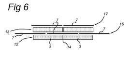
Figure 6 shows a further embodiment of adjoining reinforcement helices. - As shown in
figure 1 , in the method according to the invention use is made of amandrel 1 the rotational direction of which has been indicated. Onto saidmandrel 1, aplastic strip 2 is wound in such a way that theturns 3 thereof abut each other (see the section according tofigure 3 ). The abutting edges of adjoining helices of theplastic layer 12 are fused or welded together as a result of the heated state of theplastic strip 2, whereby afirst plastic layer 12 is formed. Subsequently, the reinforcement means 4 are wound onto thewound plastic layer 12, forming areinforcement layer 16. Said reinforcement means 4 has the form of a net or web which consists ofmain reinforcement fibers 5 which extend in the longitudinal direction of said net or web, as well as transversely extending auxiliary fibers 6 (seefigure 2 ). Good results are obtained in case the width of the reinforcement net or web is smaller than the diameter of the pipe obtained. - The net 4 is wound onto the
wound plastic strip 2 in such a way that theturns 7 of said net 4 abut each other (see the section according tofigure 3 ). The turns 7 of thenet 4 of the onereinforcement layer 16 bridge theturns 7 of thenet 4 of theother reinforcement layer 17, in such a way that a strong and stiff interconnection between the reinforcement layers 16, 17 is obtained, as is shown on a larger scale infigure 4 . - Preferably, the pitch angle 15 (see
figure 2 ) of each turn is relatively small, for instance maximally 20°. Said pitch angle is defined as the angle between the full circle around the pipe axis, and the helically extending edge of the plastic strip of the reinforcement means. Next, a furtherplastic strip 8 is wound onto the combination consisting of thefirst plastic layer 12 and the net 4 whereby asecond plastic layer 13 is formed. Furthermore, theturns 4 of the reinforcement layer bridge theturns 3 of one or both of the plastic layers 12, 13. However, the main function of the plastic layers is to provide the required fluid tightness of the pipe in question, and to provide plastic material which penetrates into the open spaces of the reinforcement nets 4 (see the section offigure 3 ). In such a way acoherent pipe wall 10 is obtained, in particular as a result of the fact that the heated plastic material of thelayers net 4. - As shown in
figure 3 , themain reinforcement fibers 5 of the net 4, although helically oriented, have a main orientation in the circumferential direction of the pipe. Theauxiliary fibers 6 are mainly oriented in the longitudinal direction of the pipe. Thereby, the required stiffness and strength both and circumferential direction and in longitudinal direction of the pipe can be obtained. As is usual, the plastic strips 2, 8 are applied onto the mandrel while in a heated, softened state. Thereby, the plastic material of saidplastic strips apertures 11 of the net 4, in such a way that a solid and coherent pipe wall will be obtained as mentioned before. - As shown in
figure 5 , theturns 7 of a plastic layer may slightly overlap each other (see the section according tofigure 5 ). Thereby, an interconnection of the turns of a single reinforcement layer is obtained. However, this layout introduces an unevenness in the reinforcement layer which is not always beneficial. -
Figure 6 shows a further embodiment, according to which the plastic layers 12, 13 have turns which cover each other without bridging each other. However, theturns 7 of thenet reinforcement 4 of one of the reinforcement layers 16 do bridge the turns of theother reinforcement layer 17, in such a way that the one of theplastic layer 13 is interposed between the reinforcement layers 16, 17. Thereby as well, a strong and stiff interconnection of theturns - Although two plastic layers and a single reinforcement layer are shown in the embodiment described before, it will be clear that further plastic layers and reinforcement layers can de added. Also, different types of materials may be used for the different layers.
-
- 1.
- Mandrel
- 2.
- Plastic strip
- 3.
- Turn
plastic strip 2 - 4.
- Reinforcement net
- 5.
- Main fiber of reinforcement net
- 6.
- Auxiliary fiber of reinforcement net
- 7.
- Turn of reinforcement net
- 8.
- Plastic strip
- 9.
- Turn of
plastic strip 8 - 10.
- Pipe wall
- 11.
- Aperture
- 12.
- Plastic layer
- 13.
- Plastic layer
- 14.
- Weld
- 15.
- Pitch angle
- 16.
- Reinforcement layer
- 17.
- Reinforcement layer
Claims (15)
- Method for manufacturing a wound plastic pipe, comprising the steps of:- providing a core (1),- providing reinforcement means (4) which comprises reinforcement fibers (5, 6),- helically winding a reinforcement means (4) onto said core (1) according to turns (7),- helically winding at least one further reinforcement means (4) according to turns (7) with the same pitch and the same winding direction as an other reinforcement means (4),- making the turns of one reinforcement means bridge the turns of an other reinforcement means.- helically winding a plastic strip (8) according to abutting turns.
- Method according to claim 1, comprising the step of:- arranging adjoining turns of a reinforcement means according to a non-overlapping relationship.
- Method according to claim 1 or 2, comprising the step of:- making the adjoining turns of a reinforcement means abut each other.
- Method according to any of claims 1-3, comprising the step:- providing a plastic pipe core.
- Method according to any of claims 1-3, comprising the step of:- providing the a mandrel core.
- Method according to claims 5, comprising the step of:- helically winding a plastic strip (2) onto the mandrel according to adjoining turns which abut one another.
- Method according to claim 6, comprising the step of:- making the turns of a reinforcement means (4) bridge the adjoining turns (3) of said plastic strip (2)
- Method according to any of the preceding claims, comprising the step of:- providing an elongate reinforcement means (4) comprising main reinforcement fibers (5) which extend in the longitudinal direction of the elongate reinforcement means (4) and auxiliary fibers (6) which extend transversely with respect to the main fibers (5).
- Method according to any of the preceding claims, comprising the step of:- winding the reinforcement means (4) and at least one plastic strip (2) according to the same pitch, the pitch angle preferably being at most 20 degrees.
- Method according to any of the preceding claims, comprising the step of:- helically winding a reinforcement means (4) having a width which is smaller than the pipe diameter.
- Method according to any of the preceding claims, comprising the step of:- helically winding a reinforcement means directly onto another reinforcement means, such that the turns the second reinforcement means bridge the adjoining turns of said other reinforcement means.
- Method according to any of the preceding claims, comprising the step of:- providing a helically wound plastic strip between two helically wound reinforcement means.
- Method according to any of the preceding claims, comprising the step of:- providing a reinforcement means (4) having a web like or net like structure.
- Wound plastic pipe manufactured according to a method of any of claims 1-13, comprising a core (2), a helically wound first reinforcement means (4) comprising reinforcement fibers (5, 6) and extending around said core (2), a helically wound second reinforcement means extending around the core (2) and the first reinforcement means (4), the turns of the second reinforcement means bridging the turns of the first reinforcement means and with the same pitch and the same winding direction as an other reinforcement means.
- Plastic pipe according to claim 14, wherein the reinforcement means (4) comprises helically extending main reinforcement fibers (5) and auxiliary fibers (6) which are oriented transversely with respect to the main reinforcement fibers (5).
Priority Applications (1)
| Application Number | Priority Date | Filing Date | Title |
|---|---|---|---|
| EP20080160327 EP2146126B1 (en) | 2008-07-14 | 2008-07-14 | Method for manufacturing a helically wound pipe |
Applications Claiming Priority (1)
| Application Number | Priority Date | Filing Date | Title |
|---|---|---|---|
| EP20080160327 EP2146126B1 (en) | 2008-07-14 | 2008-07-14 | Method for manufacturing a helically wound pipe |
Publications (2)
| Publication Number | Publication Date |
|---|---|
| EP2146126A1 true EP2146126A1 (en) | 2010-01-20 |
| EP2146126B1 EP2146126B1 (en) | 2013-01-23 |
Family
ID=40139115
Family Applications (1)
| Application Number | Title | Priority Date | Filing Date |
|---|---|---|---|
| EP20080160327 Active EP2146126B1 (en) | 2008-07-14 | 2008-07-14 | Method for manufacturing a helically wound pipe |
Country Status (1)
| Country | Link |
|---|---|
| EP (1) | EP2146126B1 (en) |
Cited By (8)
| Publication number | Priority date | Publication date | Assignee | Title |
|---|---|---|---|---|
| CN103511764A (en) * | 2012-12-26 | 2014-01-15 | 伦慧东 | Fiber reinforcement inflaming retarding anti-static electricity thin-wall steel plastic composite pipe and forming process thereof |
| CN103615606A (en) * | 2013-12-06 | 2014-03-05 | 葛介昌 | Large-caliber steel-plastic reinforced composite pipe section and reinforced composite pipe forming process |
| EP2772343A1 (en) * | 2013-03-01 | 2014-09-03 | Bell Helicopter Textron Inc. | Method of manufacturing composite core |
| EP2772344A1 (en) * | 2013-03-01 | 2014-09-03 | Bell Helicopter Textron Inc. | System and method of manufacturing composite core |
| WO2016102618A1 (en) * | 2014-12-24 | 2016-06-30 | Shell Internationale Research Maatschappij B.V. | Process for manufacturing a tube or a vessel of composite material |
| US10131108B2 (en) | 2013-03-01 | 2018-11-20 | Bell Helicopter Textron Inc. | System and method of manufacturing composite core |
| CN110978473A (en) * | 2019-12-30 | 2020-04-10 | 安徽杰蓝特新材料有限公司 | A inseparable winding equipment for compound pipe of RTP |
| CN111959008A (en) * | 2020-07-09 | 2020-11-20 | 张毅 | Preparation method of high-strength bamboo fiber winding composite pipe |
Citations (10)
| Publication number | Priority date | Publication date | Assignee | Title |
|---|---|---|---|---|
| US2783173A (en) * | 1954-07-01 | 1957-02-26 | Resistoflex Corp | Method of making laminated tubing |
| GB840602A (en) * | 1957-01-11 | 1960-07-06 | Resistoflex Corp | A chemically inert tube and a process for its manufacture |
| US4104095A (en) * | 1976-11-17 | 1978-08-01 | Shaw William D | Method for producing tubular article |
| GB1588122A (en) * | 1976-09-30 | 1981-04-15 | British Industrial Plastics | Tubes and their manufacture |
| JPS5782022A (en) * | 1980-11-10 | 1982-05-22 | Dainippon Ink & Chem Inc | Method for continuously manufacturing compound pipe |
| US4459168A (en) * | 1980-08-08 | 1984-07-10 | Anselm Anthony C | Method and apparatus for forming wire reinforced hose |
| US5362528A (en) * | 1988-09-23 | 1994-11-08 | Hobas Engineering | Multi-layer pipe conduit having components of plastic material, inorganic filler material and glass fibers |
| DE29606611U1 (en) * | 1996-04-11 | 1996-07-04 | Paul & Co Inh K Kunert Soehne | Winding tube |
| EP1088645A2 (en) * | 1999-10-01 | 2001-04-04 | Ing. Klaus Burk GmbH | Method and apparatus for manufacturing a core for winding a web material, and winding core produced thereby |
| WO2005053933A1 (en) | 2003-11-24 | 2005-06-16 | Krah Ag | Device and method for producing filament-wound pipes |
-
2008
- 2008-07-14 EP EP20080160327 patent/EP2146126B1/en active Active
Patent Citations (10)
| Publication number | Priority date | Publication date | Assignee | Title |
|---|---|---|---|---|
| US2783173A (en) * | 1954-07-01 | 1957-02-26 | Resistoflex Corp | Method of making laminated tubing |
| GB840602A (en) * | 1957-01-11 | 1960-07-06 | Resistoflex Corp | A chemically inert tube and a process for its manufacture |
| GB1588122A (en) * | 1976-09-30 | 1981-04-15 | British Industrial Plastics | Tubes and their manufacture |
| US4104095A (en) * | 1976-11-17 | 1978-08-01 | Shaw William D | Method for producing tubular article |
| US4459168A (en) * | 1980-08-08 | 1984-07-10 | Anselm Anthony C | Method and apparatus for forming wire reinforced hose |
| JPS5782022A (en) * | 1980-11-10 | 1982-05-22 | Dainippon Ink & Chem Inc | Method for continuously manufacturing compound pipe |
| US5362528A (en) * | 1988-09-23 | 1994-11-08 | Hobas Engineering | Multi-layer pipe conduit having components of plastic material, inorganic filler material and glass fibers |
| DE29606611U1 (en) * | 1996-04-11 | 1996-07-04 | Paul & Co Inh K Kunert Soehne | Winding tube |
| EP1088645A2 (en) * | 1999-10-01 | 2001-04-04 | Ing. Klaus Burk GmbH | Method and apparatus for manufacturing a core for winding a web material, and winding core produced thereby |
| WO2005053933A1 (en) | 2003-11-24 | 2005-06-16 | Krah Ag | Device and method for producing filament-wound pipes |
Non-Patent Citations (1)
| Title |
|---|
| DATABASE WPI Week 198226, Derwent World Patents Index; AN 1982-53545E, XP002510560 * |
Cited By (13)
| Publication number | Priority date | Publication date | Assignee | Title |
|---|---|---|---|---|
| CN103511764A (en) * | 2012-12-26 | 2014-01-15 | 伦慧东 | Fiber reinforcement inflaming retarding anti-static electricity thin-wall steel plastic composite pipe and forming process thereof |
| CN103511764B (en) * | 2012-12-26 | 2015-09-30 | 伦慧东 | Fiber reinforcement flame-retardant and anti-static Steel Thin-Wall plastic composite and moulding process thereof |
| EP2772344A1 (en) * | 2013-03-01 | 2014-09-03 | Bell Helicopter Textron Inc. | System and method of manufacturing composite core |
| EP2772343A1 (en) * | 2013-03-01 | 2014-09-03 | Bell Helicopter Textron Inc. | Method of manufacturing composite core |
| US9145277B2 (en) | 2013-03-01 | 2015-09-29 | Bell Helicopter Textron Inc. | System and method of manufacturing composite core |
| US9302869B2 (en) | 2013-03-01 | 2016-04-05 | Bell Helicopter Textron Inc. | System and method of manufacturing composite core |
| US10131108B2 (en) | 2013-03-01 | 2018-11-20 | Bell Helicopter Textron Inc. | System and method of manufacturing composite core |
| CN103615606B (en) * | 2013-12-06 | 2015-08-05 | 葛介昌 | Large-diameter steel plastic reinforced composite pipe joint and reinforced composite pipe moulding process |
| CN103615606A (en) * | 2013-12-06 | 2014-03-05 | 葛介昌 | Large-caliber steel-plastic reinforced composite pipe section and reinforced composite pipe forming process |
| WO2016102618A1 (en) * | 2014-12-24 | 2016-06-30 | Shell Internationale Research Maatschappij B.V. | Process for manufacturing a tube or a vessel of composite material |
| CN110978473A (en) * | 2019-12-30 | 2020-04-10 | 安徽杰蓝特新材料有限公司 | A inseparable winding equipment for compound pipe of RTP |
| CN111959008A (en) * | 2020-07-09 | 2020-11-20 | 张毅 | Preparation method of high-strength bamboo fiber winding composite pipe |
| CN111959008B (en) * | 2020-07-09 | 2022-03-11 | 张毅 | Preparation method of high-strength bamboo fiber winding composite pipe |
Also Published As
| Publication number | Publication date |
|---|---|
| EP2146126B1 (en) | 2013-01-23 |
Similar Documents
| Publication | Publication Date | Title |
|---|---|---|
| EP2146126B1 (en) | Method for manufacturing a helically wound pipe | |
| US5281454A (en) | Closed composite sections with bonded scarf joints | |
| DE60121779T2 (en) | HIGH PRESSURE COMPRESSION TUBE AND METHOD FOR PRODUCING THE TUBE | |
| DE60103673T2 (en) | Liquid-impermeable composite hose | |
| EP1827811A1 (en) | Plastic hollow body, especially plastic tube | |
| CN203892741U (en) | Enhanced type plastic steel winding tubular product | |
| EP3814663A1 (en) | Coated pipe and pipe combination | |
| WO2016173586A1 (en) | Pressure vessel for storing fluids under pressure and method for manufacturing the pressure vessel | |
| CN104279379A (en) | Continuously wound reinforced corrugated pipe and manufacturing method thereof | |
| HUE035740T2 (en) | A masonry reinforcement structure comprising parallel cords | |
| DE3242271A1 (en) | MULTIPLE PIPE | |
| EP2254745B1 (en) | Method for producing a multilayer pipe from plastic and plastic pipe produced according to said method | |
| DK2185343T3 (en) | HEATING SPIRAL COUPLER- | |
| CN102797917B (en) | Pressure pipe wound by polyethylene sandwich reinforcement rib plate strips in reciprocating manner and machining method | |
| DE102011076608A1 (en) | Joint connection i.e. T-joint, for sandwich plate for e.g. structural work, has core layer, and adhesive layer applied on core layer, where connection has form of fillet weld or double-hollow fillet weld in cross-section | |
| HUE025245T2 (en) | Method of manufacturing a pipe from thermoplastic material | |
| EP1133653B1 (en) | Method of making a pipe, and a pipe | |
| US20070122579A1 (en) | Fibre-reinforced plastic tube | |
| JP5588216B2 (en) | Manufacturing method of band member with reinforcing material for pipe made of rehabilitation pipe | |
| EP2106897A1 (en) | Plastic pipe with profiled layer and method for manufacturing the same | |
| AU709765B2 (en) | A cable sheath having a multilayer structure, a method of manufacturing such a sheath, and a machine for implementing the method | |
| DE10164367C1 (en) | Device for holding elastic sleeve open while it is fitted over cables comprises spiral-shaped thermoplastic profile whose windings are bonded together in some areas, in which thermoplastic is crosslinked | |
| JPWO2007111051A1 (en) | Synthetic resin tube and manufacturing method thereof | |
| CN215172913U (en) | Polyethylene M-type multi-rib structure composite reinforced winding pipe | |
| CN211289063U (en) | High-temperature-resistant steel-band reinforced polyethylene spiral corrugated pipe |
Legal Events
| Date | Code | Title | Description |
|---|---|---|---|
| PUAI | Public reference made under article 153(3) epc to a published international application that has entered the european phase |
Free format text: ORIGINAL CODE: 0009012 |
|
| AK | Designated contracting states |
Kind code of ref document: A1 Designated state(s): AT BE BG CH CY CZ DE DK EE ES FI FR GB GR HR HU IE IS IT LI LT LU LV MC MT NL NO PL PT RO SE SI SK TR |
|
| AX | Request for extension of the european patent |
Extension state: AL BA MK RS |
|
| 17P | Request for examination filed |
Effective date: 20100601 |
|
| 17Q | First examination report despatched |
Effective date: 20100628 |
|
| AKX | Designation fees paid |
Designated state(s): AT BE BG CH CY CZ DE DK EE ES FI FR GB GR HR HU IE IS IT LI LT LU LV MC MT NL NO PL PT RO SE SI SK TR |
|
| REG | Reference to a national code |
Ref country code: DE Ref legal event code: R079 Ref document number: 602008021827 Country of ref document: DE Free format text: PREVIOUS MAIN CLASS: F16L0009160000 Ipc: B29C0053580000 |
|
| GRAP | Despatch of communication of intention to grant a patent |
Free format text: ORIGINAL CODE: EPIDOSNIGR1 |
|
| RIC1 | Information provided on ipc code assigned before grant |
Ipc: B29C 70/32 20060101ALI20120710BHEP Ipc: B29C 53/62 20060101ALI20120710BHEP Ipc: F16L 9/16 20060101ALI20120710BHEP Ipc: F16L 11/08 20060101ALN20120710BHEP Ipc: B29C 53/58 20060101AFI20120710BHEP Ipc: B29C 70/02 20060101ALN20120710BHEP Ipc: B29C 70/08 20060101ALN20120710BHEP |
|
| GRAS | Grant fee paid |
Free format text: ORIGINAL CODE: EPIDOSNIGR3 |
|
| GRAA | (expected) grant |
Free format text: ORIGINAL CODE: 0009210 |
|
| AK | Designated contracting states |
Kind code of ref document: B1 Designated state(s): AT BE BG CH CY CZ DE DK EE ES FI FR GB GR HR HU IE IS IT LI LT LU LV MC MT NL NO PL PT RO SE SI SK TR |
|
| REG | Reference to a national code |
Ref country code: GB Ref legal event code: FG4D |
|
| REG | Reference to a national code |
Ref country code: CH Ref legal event code: EP |
|
| REG | Reference to a national code |
Ref country code: AT Ref legal event code: REF Ref document number: 594714 Country of ref document: AT Kind code of ref document: T Effective date: 20130215 Ref country code: CH Ref legal event code: EP |
|
| REG | Reference to a national code |
Ref country code: IE Ref legal event code: FG4D |
|
| REG | Reference to a national code |
Ref country code: DE Ref legal event code: R096 Ref document number: 602008021827 Country of ref document: DE Effective date: 20130321 |
|
| REG | Reference to a national code |
Ref country code: AT Ref legal event code: MK05 Ref document number: 594714 Country of ref document: AT Kind code of ref document: T Effective date: 20130123 |
|
| REG | Reference to a national code |
Ref country code: LT Ref legal event code: MG4D |
|
| REG | Reference to a national code |
Ref country code: NL Ref legal event code: VDEP Effective date: 20130123 |
|
| PG25 | Lapsed in a contracting state [announced via postgrant information from national office to epo] |
Ref country code: NO Free format text: LAPSE BECAUSE OF FAILURE TO SUBMIT A TRANSLATION OF THE DESCRIPTION OR TO PAY THE FEE WITHIN THE PRESCRIBED TIME-LIMIT Effective date: 20130423 Ref country code: IS Free format text: LAPSE BECAUSE OF FAILURE TO SUBMIT A TRANSLATION OF THE DESCRIPTION OR TO PAY THE FEE WITHIN THE PRESCRIBED TIME-LIMIT Effective date: 20130523 Ref country code: SE Free format text: LAPSE BECAUSE OF FAILURE TO SUBMIT A TRANSLATION OF THE DESCRIPTION OR TO PAY THE FEE WITHIN THE PRESCRIBED TIME-LIMIT Effective date: 20130123 Ref country code: LT Free format text: LAPSE BECAUSE OF FAILURE TO SUBMIT A TRANSLATION OF THE DESCRIPTION OR TO PAY THE FEE WITHIN THE PRESCRIBED TIME-LIMIT Effective date: 20130123 Ref country code: ES Free format text: LAPSE BECAUSE OF FAILURE TO SUBMIT A TRANSLATION OF THE DESCRIPTION OR TO PAY THE FEE WITHIN THE PRESCRIBED TIME-LIMIT Effective date: 20130504 Ref country code: BE Free format text: LAPSE BECAUSE OF FAILURE TO SUBMIT A TRANSLATION OF THE DESCRIPTION OR TO PAY THE FEE WITHIN THE PRESCRIBED TIME-LIMIT Effective date: 20130123 Ref country code: AT Free format text: LAPSE BECAUSE OF FAILURE TO SUBMIT A TRANSLATION OF THE DESCRIPTION OR TO PAY THE FEE WITHIN THE PRESCRIBED TIME-LIMIT Effective date: 20130123 Ref country code: BG Free format text: LAPSE BECAUSE OF FAILURE TO SUBMIT A TRANSLATION OF THE DESCRIPTION OR TO PAY THE FEE WITHIN THE PRESCRIBED TIME-LIMIT Effective date: 20130423 |
|
| PG25 | Lapsed in a contracting state [announced via postgrant information from national office to epo] |
Ref country code: PT Free format text: LAPSE BECAUSE OF FAILURE TO SUBMIT A TRANSLATION OF THE DESCRIPTION OR TO PAY THE FEE WITHIN THE PRESCRIBED TIME-LIMIT Effective date: 20130523 Ref country code: PL Free format text: LAPSE BECAUSE OF FAILURE TO SUBMIT A TRANSLATION OF THE DESCRIPTION OR TO PAY THE FEE WITHIN THE PRESCRIBED TIME-LIMIT Effective date: 20130123 Ref country code: GR Free format text: LAPSE BECAUSE OF FAILURE TO SUBMIT A TRANSLATION OF THE DESCRIPTION OR TO PAY THE FEE WITHIN THE PRESCRIBED TIME-LIMIT Effective date: 20130424 Ref country code: FI Free format text: LAPSE BECAUSE OF FAILURE TO SUBMIT A TRANSLATION OF THE DESCRIPTION OR TO PAY THE FEE WITHIN THE PRESCRIBED TIME-LIMIT Effective date: 20130123 Ref country code: LV Free format text: LAPSE BECAUSE OF FAILURE TO SUBMIT A TRANSLATION OF THE DESCRIPTION OR TO PAY THE FEE WITHIN THE PRESCRIBED TIME-LIMIT Effective date: 20130123 Ref country code: NL Free format text: LAPSE BECAUSE OF FAILURE TO SUBMIT A TRANSLATION OF THE DESCRIPTION OR TO PAY THE FEE WITHIN THE PRESCRIBED TIME-LIMIT Effective date: 20130123 Ref country code: SI Free format text: LAPSE BECAUSE OF FAILURE TO SUBMIT A TRANSLATION OF THE DESCRIPTION OR TO PAY THE FEE WITHIN THE PRESCRIBED TIME-LIMIT Effective date: 20130123 |
|
| PG25 | Lapsed in a contracting state [announced via postgrant information from national office to epo] |
Ref country code: HR Free format text: LAPSE BECAUSE OF FAILURE TO SUBMIT A TRANSLATION OF THE DESCRIPTION OR TO PAY THE FEE WITHIN THE PRESCRIBED TIME-LIMIT Effective date: 20130123 |
|
| PG25 | Lapsed in a contracting state [announced via postgrant information from national office to epo] |
Ref country code: CZ Free format text: LAPSE BECAUSE OF FAILURE TO SUBMIT A TRANSLATION OF THE DESCRIPTION OR TO PAY THE FEE WITHIN THE PRESCRIBED TIME-LIMIT Effective date: 20130123 Ref country code: RO Free format text: LAPSE BECAUSE OF FAILURE TO SUBMIT A TRANSLATION OF THE DESCRIPTION OR TO PAY THE FEE WITHIN THE PRESCRIBED TIME-LIMIT Effective date: 20130123 Ref country code: DK Free format text: LAPSE BECAUSE OF FAILURE TO SUBMIT A TRANSLATION OF THE DESCRIPTION OR TO PAY THE FEE WITHIN THE PRESCRIBED TIME-LIMIT Effective date: 20130123 Ref country code: SK Free format text: LAPSE BECAUSE OF FAILURE TO SUBMIT A TRANSLATION OF THE DESCRIPTION OR TO PAY THE FEE WITHIN THE PRESCRIBED TIME-LIMIT Effective date: 20130123 Ref country code: EE Free format text: LAPSE BECAUSE OF FAILURE TO SUBMIT A TRANSLATION OF THE DESCRIPTION OR TO PAY THE FEE WITHIN THE PRESCRIBED TIME-LIMIT Effective date: 20130123 |
|
| PG25 | Lapsed in a contracting state [announced via postgrant information from national office to epo] |
Ref country code: CY Free format text: LAPSE BECAUSE OF FAILURE TO SUBMIT A TRANSLATION OF THE DESCRIPTION OR TO PAY THE FEE WITHIN THE PRESCRIBED TIME-LIMIT Effective date: 20130123 |
|
| PLBE | No opposition filed within time limit |
Free format text: ORIGINAL CODE: 0009261 |
|
| STAA | Information on the status of an ep patent application or granted ep patent |
Free format text: STATUS: NO OPPOSITION FILED WITHIN TIME LIMIT |
|
| PG25 | Lapsed in a contracting state [announced via postgrant information from national office to epo] |
Ref country code: IT Free format text: LAPSE BECAUSE OF FAILURE TO SUBMIT A TRANSLATION OF THE DESCRIPTION OR TO PAY THE FEE WITHIN THE PRESCRIBED TIME-LIMIT Effective date: 20130123 |
|
| 26N | No opposition filed |
Effective date: 20131024 |
|
| REG | Reference to a national code |
Ref country code: DE Ref legal event code: R097 Ref document number: 602008021827 Country of ref document: DE Effective date: 20131024 |
|
| PG25 | Lapsed in a contracting state [announced via postgrant information from national office to epo] |
Ref country code: MC Free format text: LAPSE BECAUSE OF FAILURE TO SUBMIT A TRANSLATION OF THE DESCRIPTION OR TO PAY THE FEE WITHIN THE PRESCRIBED TIME-LIMIT Effective date: 20130123 |
|
| PG25 | Lapsed in a contracting state [announced via postgrant information from national office to epo] |
Ref country code: MT Free format text: LAPSE BECAUSE OF FAILURE TO SUBMIT A TRANSLATION OF THE DESCRIPTION OR TO PAY THE FEE WITHIN THE PRESCRIBED TIME-LIMIT Effective date: 20130123 Ref country code: TR Free format text: LAPSE BECAUSE OF FAILURE TO SUBMIT A TRANSLATION OF THE DESCRIPTION OR TO PAY THE FEE WITHIN THE PRESCRIBED TIME-LIMIT Effective date: 20130123 |
|
| PG25 | Lapsed in a contracting state [announced via postgrant information from national office to epo] |
Ref country code: LU Free format text: LAPSE BECAUSE OF NON-PAYMENT OF DUE FEES Effective date: 20130714 Ref country code: HU Free format text: LAPSE BECAUSE OF FAILURE TO SUBMIT A TRANSLATION OF THE DESCRIPTION OR TO PAY THE FEE WITHIN THE PRESCRIBED TIME-LIMIT; INVALID AB INITIO Effective date: 20080714 |
|
| REG | Reference to a national code |
Ref country code: FR Ref legal event code: PLFP Year of fee payment: 9 |
|
| REG | Reference to a national code |
Ref country code: FR Ref legal event code: PLFP Year of fee payment: 10 |
|
| REG | Reference to a national code |
Ref country code: FR Ref legal event code: PLFP Year of fee payment: 11 |
|
| P01 | Opt-out of the competence of the unified patent court (upc) registered |
Effective date: 20230527 |
|
| PGFP | Annual fee paid to national office [announced via postgrant information from national office to epo] |
Ref country code: IE Payment date: 20230718 Year of fee payment: 16 Ref country code: GB Payment date: 20230725 Year of fee payment: 16 Ref country code: CH Payment date: 20230802 Year of fee payment: 16 |
|
| PGFP | Annual fee paid to national office [announced via postgrant information from national office to epo] |
Ref country code: FR Payment date: 20230725 Year of fee payment: 16 Ref country code: DE Payment date: 20230726 Year of fee payment: 16 |