EP2146385A1 - High resolution focused ultrasonic transducer - Google Patents
High resolution focused ultrasonic transducer Download PDFInfo
- Publication number
- EP2146385A1 EP2146385A1 EP09157478A EP09157478A EP2146385A1 EP 2146385 A1 EP2146385 A1 EP 2146385A1 EP 09157478 A EP09157478 A EP 09157478A EP 09157478 A EP09157478 A EP 09157478A EP 2146385 A1 EP2146385 A1 EP 2146385A1
- Authority
- EP
- European Patent Office
- Prior art keywords
- transducer
- piezoelectric
- bonded
- backing
- package
- Prior art date
- Legal status (The legal status is an assumption and is not a legal conclusion. Google has not performed a legal analysis and makes no representation as to the accuracy of the status listed.)
- Withdrawn
Links
Images


Classifications
-
- G—PHYSICS
- G01—MEASURING; TESTING
- G01N—INVESTIGATING OR ANALYSING MATERIALS BY DETERMINING THEIR CHEMICAL OR PHYSICAL PROPERTIES
- G01N29/00—Investigating or analysing materials by the use of ultrasonic, sonic or infrasonic waves; Visualisation of the interior of objects by transmitting ultrasonic or sonic waves through the object
- G01N29/22—Details, e.g. general constructional or apparatus details
- G01N29/24—Probes
- G01N29/2437—Piezoelectric probes
-
- B—PERFORMING OPERATIONS; TRANSPORTING
- B06—GENERATING OR TRANSMITTING MECHANICAL VIBRATIONS IN GENERAL
- B06B—METHODS OR APPARATUS FOR GENERATING OR TRANSMITTING MECHANICAL VIBRATIONS OF INFRASONIC, SONIC, OR ULTRASONIC FREQUENCY, e.g. FOR PERFORMING MECHANICAL WORK IN GENERAL
- B06B3/00—Methods or apparatus specially adapted for transmitting mechanical vibrations of infrasonic, sonic, or ultrasonic frequency
- B06B3/04—Methods or apparatus specially adapted for transmitting mechanical vibrations of infrasonic, sonic, or ultrasonic frequency involving focusing or reflecting
-
- G—PHYSICS
- G01—MEASURING; TESTING
- G01N—INVESTIGATING OR ANALYSING MATERIALS BY DETERMINING THEIR CHEMICAL OR PHYSICAL PROPERTIES
- G01N29/00—Investigating or analysing materials by the use of ultrasonic, sonic or infrasonic waves; Visualisation of the interior of objects by transmitting ultrasonic or sonic waves through the object
- G01N29/22—Details, e.g. general constructional or apparatus details
- G01N29/24—Probes
- G01N29/2456—Focusing probes
-
- G—PHYSICS
- G10—MUSICAL INSTRUMENTS; ACOUSTICS
- G10K—SOUND-PRODUCING DEVICES; METHODS OR DEVICES FOR PROTECTING AGAINST, OR FOR DAMPING, NOISE OR OTHER ACOUSTIC WAVES IN GENERAL; ACOUSTICS NOT OTHERWISE PROVIDED FOR
- G10K11/00—Methods or devices for transmitting, conducting or directing sound in general; Methods or devices for protecting against, or for damping, noise or other acoustic waves in general
- G10K11/004—Mounting transducers, e.g. provided with mechanical moving or orienting device
- G10K11/006—Transducer mounting in underwater equipment, e.g. sonobuoys
-
- G—PHYSICS
- G10—MUSICAL INSTRUMENTS; ACOUSTICS
- G10K—SOUND-PRODUCING DEVICES; METHODS OR DEVICES FOR PROTECTING AGAINST, OR FOR DAMPING, NOISE OR OTHER ACOUSTIC WAVES IN GENERAL; ACOUSTICS NOT OTHERWISE PROVIDED FOR
- G10K11/00—Methods or devices for transmitting, conducting or directing sound in general; Methods or devices for protecting against, or for damping, noise or other acoustic waves in general
- G10K11/18—Methods or devices for transmitting, conducting or directing sound
- G10K11/26—Sound-focusing or directing, e.g. scanning
- G10K11/30—Sound-focusing or directing, e.g. scanning using refraction, e.g. acoustic lenses
-
- B—PERFORMING OPERATIONS; TRANSPORTING
- B06—GENERATING OR TRANSMITTING MECHANICAL VIBRATIONS IN GENERAL
- B06B—METHODS OR APPARATUS FOR GENERATING OR TRANSMITTING MECHANICAL VIBRATIONS OF INFRASONIC, SONIC, OR ULTRASONIC FREQUENCY, e.g. FOR PERFORMING MECHANICAL WORK IN GENERAL
- B06B2201/00—Indexing scheme associated with B06B1/0207 for details covered by B06B1/0207 but not provided for in any of its subgroups
- B06B2201/70—Specific application
-
- G—PHYSICS
- G01—MEASURING; TESTING
- G01N—INVESTIGATING OR ANALYSING MATERIALS BY DETERMINING THEIR CHEMICAL OR PHYSICAL PROPERTIES
- G01N2291/00—Indexing codes associated with group G01N29/00
- G01N2291/02—Indexing codes associated with the analysed material
- G01N2291/023—Solids
- G01N2291/0231—Composite or layered materials
-
- G—PHYSICS
- G01—MEASURING; TESTING
- G01N—INVESTIGATING OR ANALYSING MATERIALS BY DETERMINING THEIR CHEMICAL OR PHYSICAL PROPERTIES
- G01N2291/00—Indexing codes associated with group G01N29/00
- G01N2291/04—Wave modes and trajectories
- G01N2291/045—External reflections, e.g. on reflectors
-
- G—PHYSICS
- G01—MEASURING; TESTING
- G01N—INVESTIGATING OR ANALYSING MATERIALS BY DETERMINING THEIR CHEMICAL OR PHYSICAL PROPERTIES
- G01N2291/00—Indexing codes associated with group G01N29/00
- G01N2291/26—Scanned objects
- G01N2291/263—Surfaces
- G01N2291/2636—Surfaces cylindrical from inside
Definitions
- the present invention relates to transducers, to tools utilizing such transducers and to methods of making and using transducers.
- the present invention relates to transducers for use in both logging while drilling ("LWD") and wireline applications, to tools utilizing such transducers and to methods of making and using such transducers.
- the present invention relates to transducers with minimal reverberation, to tools utilizing such transducers and to methods of making and using such transducers.
- Well bores are lined with steel casing to prevent collapse of the bore while drilling and to prevent fluid communication between productive oil and gas bearing formations and nonproductive formation, such as those bearing water.
- a cement slurry is pumped downhole through this casing and displaced up into the annular space between the casing and the borehole wall where it hardens . Once the formations are separated by the cementing process, the desired formations are perforated for production.
- Acoustic imaging tools utilizing transducers are used to evaluate the condition of the cement by directing sonic pulses trough the casing, through the cement and to the rock formations.
- these tools consist of a transmitter capable of providing acoustical impulses, and at least one receiver responsive to acoustical energy, mounted on a support for movement through the length of the well bore.
- the transmitter transducer is also the receiver.
- the transmitter and receiver are spaced apart by a fixed distance.
- the energy from acoustic pulses periodically generated by the transmitter propagates to the wall, reflects (or refracts), propagates back to the receiver, and is picked up at the receiver.
- the amplitudes of the received signals are correlated with the depth in the well bore to provide a log indicating the qualities of the cement bonding to the bore as a function of depth in the well.
- the performance of logging while drilling caliper tools and the wireline circumferential scanning tools, pulse echo cement bond tools and cement imaging tools are degraded by reverberation in the transducers. If the reverberation can be minimized, the minimum inspection distance can be decreased, permitting nearer standoff measurements, improved bond measurement and detection of thinner cement layers behind casing. Improving the focusing of the open hole scanning transducers will give better estimations of formation surface texture.
- Present tools contain transducers having significant reverberations that interfere with signal interpretation.
- Some open-hole scanning transducers have step focusing which gives reverberations in the lens itself.
- focused caliper standoff transducers have undesirable reverberations from plastic lenses.
- the caliper/standoff transducers have radiation patterns which lose echoes for certain eccentered configurations.
- Open hole scanning transducers also need a transducer with less reverberation to operate in heavier muds than can be investigated with the transducers now available.
- the logging while drilling, formation speed of sound, and caliper standoff tools also need an improved transducer to reduce loss of signal for eccentered tools in the borehole, to investigate smaller standoffs and to handle heavier weight muds.
- a transducer package including an unpoled piezoelectric lens bonded to an active piezoelectric element.
- a transducer package including a metal faceted lens bonded to an active piezoelectric material.
- a multi-element transducer package comprising:
- a multi-element transducer package including a first transducer unit comprising a first wedge bonded a first poled piezoelectric element bonded to a first backing, a middle transducer unit comprising a second poled piezoelectric element bonded to a second backing, a second transducer unit comprising a second wedge bonded to a third poled piezoelectric element bonded to a third backing.
- the first and second units are bonded to the middle unit such that the piezoelectric elements are isolated from each other.
- the transducer materials and packaging of the present invention reduce reverberation. By minimizing the reverberation of a transducer, the minimum inspection distance can be decreased thereby permitting nearer standoff measurements, improved bond measurements, detection of thinner cement layers behind the casing, and better estimations of formation surface texture.
- the transducers of the present invention find utility in both wireline and logging while drilling applications.
- the transducer lens is made of unpoled piezoelectic material. Lenses made of this material provide for better impedance matching between the lens and the active piezoelectric thereby reducing reverberation. In addition, the lenses made of unpoled piezoelectic material have larger speed of sound which allows for shorter focal lengths than the current lenses made of epoxy.
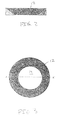
- FIG. 1 is a cut away view of a transducer package, shown generally as 10, utilizing an unpoled piezoelectric lens 12.
- FIG. 2 is a cut away view of unpoled piezoelectric lens 12 of FIG. 1 as purchased from a piezoelectric manufacturer.
- FIG. 3 is a top view of transducer package 10 of FIG. 1 .
- Transducer package 10 generally includes unpoled piezoelectric lens 12 bonded to active piezoelectric element 14 bonded to absorbive backing 16. Both unpoled and active piezoelectric material are commercially available from a piezoelectric manufacturer. Non-limiting examples of suitable commercially available piezoelectric material include lead metaniobate and lead zirconate titanate.
- Backing 16 may be any suitable material, capable of withstanding downhole temperatures.
- backing 16 is a material having an acoustic impendance similar to that of the piezoelectric material being used. More preferably, backing 16 is a tungsten loaded epoxy or a tungsten loaded rubber as are known to those skilled in the art.
- Unpoled piezoelectric lens 12 is bonded to active piezoelectric element 14 at bonding layer 18 by any suitable adhesive capable of withstanding downhole temperatures. Because of matched thermal expansion coefficients of the lens 12 and active element 14, the bonding layer 18 be made with commercially available epoxy adhesives.
- Piezoelectric element 14 is bonded to backing 16 at bonding layer 22 by suitable means capable of withstanding downhole temperatures.
- bonding layer 22 is a high temperature epoxy adhesive commercially available for bonding metal to glass.
- transducer 10 is clamped together and the bonding layers allowed to cure as is known in the art. Once bonded together, transducer 10 is potted in epoxy, with the thickness of the epoxy layer dependent upon and matched to the impedance of the material transmitting through, as is known in the art.
- a second embodiment of the transducer of the present invention includes a metal faceted lens to minimize reverberation time after firing.
- the metal lens is impedance matched to the piezoelectric material.
- aluminum offers impedance matching for lead metaniobate.
- Aluminum also offers ease of machining and of assembly and allows for thinner lenses than those made of unpoled piezoelectic material or epoxy.
- titanium offers impedance matching for lead zirconate titanate
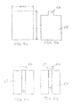
- FIG. 4 is a view of aluminum shell 52 having height h, inner radius R1 and radius R2 prior to machining to form an acoustic lens.
- FIG. 5a is a cross section of portion 54 (R2-R1) of shell 52 before machining and
- FIG. 5b is a cross section of shell 52 after the first machine cut to form retaining ring 56.
- FIG. 6a is a cross section of shell 52 after machining of groove 58 and
- FIG. 6b is a cross section of shell 52 with hidden line 57 showing the top of the radial slots after machining.
- FIG. 7 is a top view of shell 52 after machining in preparation for bonding to active piezoelectric material (not shown).
- FIG. 8 is a view of aluminum lens facet after bonding to piezoelectric and after machining while bonded to piezoelectric.
- aluminum lens 50 is machined from cylindrical aluminum shell 52 which includes outer portion 54. Before machining, shell 52 has physical dimensions of height h, inner radius R1 and radius R2. The dimensions of h, R1 and R2 are selected to provide the desired focal distances as is known in the art.
- outer section 54 of shell 52 has a cross section of R2-R1.
- a retaining ring 56 is first machined into shell 52 such that outer section 54 of shell 52 has a cross section (R2-R1) as shown in FIG. 5b .
- a circumferential groove 58 is machined into outer section 54 of shell 52 such that outer section 54 has a cross section (R2-R1). Radical grooves or slots 62 are then machined from the bottom of shell 54 such that the top view of shell 52 is as shown in FIG. 7 with retaining ring 56 being the only material connecting inner-aluminum sectors 64 and outer-aluminum sectors 66 together.
- Shell 52 as shown in FIG. 7 is bonded to the active piezoelectric element (not shown) by any suitable adhesive capable of withstanding downhole temperatures.
- the adhesive is an epoxy adhesive rated for bonding metal to glass.
- the small size of the facets reduces bonding problems due to differential thermal expansion between metal and piezoelectric.
- the piezoelectric material may be any material which may be matched in acoustic impedance to commercially available metals.
- suitable commercially available piezoelectric material and matching metals include lead metaniobate with aluminum and lead zirconate titanate with titanium.
- the active piezoelectric element now bonded to aluminum faceted lens 50, is then bonded to backing (not shown).
- the backing may be any suitable material, capable of withstanding downhole temperatures.
- the backing is a material having an acoustic impedance similar to that of the piezoelectric material being used.
- backing 16 is a tungsten loaded epoxy or a tungsten loaded rubber as are known to those skilled in the art.
- aluminum faceted lens 50 is bonded to a backing by a commercially available adhesive, capable of withstanding downhole temperatures and capable of boding metal to glass.
- the completed package is then potted in epoxy, with the thickness of the epoxy layer dependent upon and matched to the impedance of the material transmitting through, as is known in the art. Potting in this manner results in the gaps between the aluminum sectors 64 and 66 being filled with epoxy.
- Sectors 64 and 66 may be of any suitable size to prevent the active piezoelectric element from being shattered by the differential thermal expansion of the metal and the ceramic.
- the dimensions of the sectors are chosen to be smaller than an acoustical wavelength.
- facets 64 and 66 of lens 50 of second embodiment were formed of aluminum, it is understood that the facets can be machined or assembled from other suitable materials.
- facets 64 and 66 are formed from a material having an acoustic impedance closely matched to that of the piezoelectric element.
- aluminum facets have an acoustic impedance similar to that of the piezoelectric lead metaniobate
- titanium facets have an acoustic impedance similar to that of the piezoelectric lead zirconate titanate.
- facets 64 and 66 may be made from unpoled piezoelectric material which provides the advantage of versatility in lens geometries.
- a third embodiment of the transducer of the present invention includes a new acoustic isolator design which permits pitch-catch operation.
- the transmitter backing is only weakly coupled to the receiver piezoelectric thereby reducing reverberation and improving signal to noise ratio.
- This embodiment is especially important in logging while drilling transducers which require relatively short backing materials to avoid machining large holes which unacceptably weaken the drill collar.
- the new isolator design allows multiple elements for multiple direction radiation patterns which helps to avoid the loss of wall echoes when the tool is eccentered in the borehole.
- transducers packaged in this manner find utility in the cement imaging system.
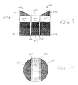
- FIG. 9 is a cross sectional view of a multi-element transducer, shown generally as 100, having unpoled piezoelectric wedges 102 and 104, poled active piezoelectric sections 106, 108 and 110, backing material 112, 114 and 116, and acoustic isolator 120 and 122.
- FIG. 10 is a top view of transducer package 100 of FIG. 9 .
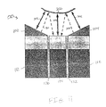
- FIG. 11 is a cross-sectional view of the propagation directions for transducer 100 of FIG. 9 .
- Transducer package 100 generally includes three active piezoelectric elements 106, 108 and 110 having individual backing 112, 114 and 116 respectfully. Element 106 is completely separated from elements 108 and 110 by acoustic isolator 120 and element 110 is completely separated from elements 108 and 106 by acoustic isolator 122 as shown in FIG. 10 .
- Active piezoelectric material for sections 106, 108 and 110 are commercially available from a piezoelectric manufacturer.
- suitable commercially available piezoelectric material include lead metaniobate and lead zirconate titanate.
- Backings 112, 114 and 116 may be any suitable material, capable of withstanding downhole temperatures.
- the backing will attenuate acoustic waves from the backing side of the active piezoelectric element so that the reverberation of such waves in such backing are attenuated.
- the backings are a material having an acoustic impedance similar to that of the piezoelectric material being used. More preferably, the backings are a tungsten loaded epoxy or a tungsten loaded rubber as are known to those skilled in the art.
- individual active piezoelectric elements 106, 108 and 110 are bonded to backings 112, 114 and 116, and unpoled piezoelectric wedges are bonded to active elements 106 and 110 to form three single units 150, 155 and 160.
- elements 106, 108 and 110 are bonded to backings 112, 114 and 116 by a commercial adhesive capable of withstanding downhole temperatures and bonding metal to glass.
- Single units 150, 155 and 160 are then tacked together with small bridges made of the epoxy used for potting with the bridges establishing the thickness of isolators 120 and 122.
- the epoxy fills the gaps established by the bridges, forming uniform thickness isolators.
- the thickness of the epoxy layer being dependent upon and matched to the impendance of the material transmitting through, as is known in the art.
- transducer 100 can be used for either pulse-echo or pitch-catch operation.
- Wedges 102 and 104 permit pulse-echo detection of surfaces which are not perpendicular to the cylindrical axis of the transducer. This feature is important for eccentered LWD tools in the borehole.
- pulse echo propagation off boundary 300 may occur in directions 302, 304 and 306 (3 places) and pitch catch propagation off boundary 300 can occur in directions 308 and 310 (2 places).
- the high frequency (0.4 MHz to 2 MHz) center transducer unit 155 can detect walls at very short standoffs. For heavy weight muds, however, high frequency signals are attenuated, limiting radial range to about 1 inch. For greater radial distances, the outer transmitter units 150 and 160 have stacked piezoelectric elements to generate powerful signals. The outer elements 106 and 110 are designed to operate at lower frequencies (100 KHz to 300 KHz) than the center transducer 108.
- the attenuation per wavelength is essentially constant, range increases inversely with transmitter frequency.
- the long ringdown reverberations of low frequency transducers 150 and 160 prevent detecting echoes for approximately the first inch of radial travel.
- the high frequency element 155 covers the range from 0.3 to 1 inch for all muds.
- the high frequency element 155 has flat response throughout the spectral range of the low frequency transducers.
- the high frequency receiver 155 is decoupled from the backing reverberations of the low frequency transmitters 150 and 160, giving good signal to noise ratio.
- the broad radiation patterns of the low frequency transducers 150 and 160 give strong signals in the center receiver 155 when both low frequency transmitters 150 and 160 are fired simultaneously.
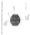
- FIG. 12 is a cross sectional view of multi-element transducer 200, having unpoled piezoelectric wedges 202 and 204, poled active piezoelectric sections 206, 208 and 210, piezoelectric for fluid velocity 224, backing material 212, 214, 216 and 218 and acoustic isolators 220 and 222.
- FIG. 13 is a top view of transducer package 200 of FIG. 12 .
- FIG. 14 is top view of transducer package 200 of FIG. 12 showing the pulse-echo acoustic path.
- FIG. 15 is top view of transducer package 200 of FIG. 12 showing the pitch-catch acoustic path.
- transducer package 200 generally includes active piezoelectric elements 206, 208 and 210 having individual backing 212, 214 and 216 respectfully. Element 206 is completely separated from elements 208 and 210 by acoustic isolator 220 and element 210 is completely separated from elements 208 and 206 by acoustic isolator 222. Transducer package 200 also includes piezoelectric element 224.
- transducer package 200 includes transmitter receiver element 224 and acoustic reflector 226.
- transducer package 200 includes transmitter piezoelectric element 224 and receiver piezoelectric element 228.
- Elements 224 and 228, when utilized, are also completely isolated from elements 206, 208 and 210 by insulators 220, 222 and 232.
- Active piezoelectric material for elements 206, 208 210, 224 and 228 are commercially available from a piezoelectric manufacturer.
- suitable commercially available piezoelectric material include lead metaniobate and lead zirconate titanate.
- Backings 212, 214 216 and 218 may be any suitable material, capable of withstanding downhole temperatures.
- the backings are a material having an acoustic impedance similar to that of the piezoelectric material being used. More preferably, the backings are a tungsten loaded epoxy or a tungsten loaded rubber as are known to those skilled in the art.
- piezoelectric elements 206, 208 and 210 are bonded to backings 212, 214 and 216, and unpoled piezoelectric wedges are bonded to active elements 206 and 210 to form three single units 250, 255 and 260.
- Piezoelectric elements 224 and 228 or piezoelectric element 224 and acoustic reflector 226 are bonded to backing 218 and tacked to piezoelectric element 208 with small bridges made of the epoxy used for potting with the bridges establishing the thickness of insulator 232.
- elements 206, 208, 210, 224 and 228, when utilized, are bonded to backings 212, 214, 216 and 218 by a commercial adhesive capable of withstanding downhole temperatures and bonding metal to glass.
- Single units 250, 255 and 260 are tacked together with small bridges made of the epoxy used for potting with the bridges establishing the thickness of isolators 220 and 222.
- the epoxy fills the gaps established by the bridges, forming isolators 220 and 222 with each insulator being of uniform thickness.
- the thickness of the epoxy layer being dependent upon and matched to the impedance of the material transmitting through, as is known in the art.
- transducer 200 can be used for either pulse-echo or pitch-catch operation.
- FIG. 14 there is shown an illustration of the pulse-echo acoustic path for transducer 200.
- piezoelectric element 224 is a transmitter/receiver. The signal is transmitted along acoustic path 402, reflected off acoustic reflector 226 and received along acoustic path 404.
- piezoelectric element 224 is a transmitter piezoelectric and piezoelectric element 228 is a receiver piezoelectric.
- the signal is transmitted from element 224 along acoustic path 406 and received by element 228.
- the outer elements 206 and 210 are designed to operate at lower frequencies than the center transducer 208.
- the elements 206 and 210 operate in the range of between about 100 KHz and about 300 KHz and elements 208 and 224 operate in the range of between about 0.4 MHz and about 2 MHz.
Abstract
There is disclosed a multi-element transducer package comprising:
(a) a first transducer unit (150) comprising a first wedge (102) bonded a first poled piezoelectric element (106) bonded to a first backing (112);
(b) a middle transducer unit (155) comprising a second poled piezoelectric element (108) bonded to a second backing (114); and
(c) a second transducer unit (160) comprising a second wedge (104) bonded to a third poled piezoelectric element (110) bonded to a third backing (116);
wherein the first and second units are bonded to the middle unit such that the piezoelectric elements are isolated from each other; and
wherein the backing material has an acoustic impedance similar to the piezoelectric elements.
Description
- The present invention relates to transducers, to tools utilizing such transducers and to methods of making and using transducers. In another aspect, the present invention relates to transducers for use in both logging while drilling ("LWD") and wireline applications, to tools utilizing such transducers and to methods of making and using such transducers. In even another aspect, the present invention relates to transducers with minimal reverberation, to tools utilizing such transducers and to methods of making and using such transducers.
- Well bores are lined with steel casing to prevent collapse of the bore while drilling and to prevent fluid communication between productive oil and gas bearing formations and nonproductive formation, such as those bearing water. A cement slurry is pumped downhole through this casing and displaced up into the annular space between the casing and the borehole wall where it hardens . Once the formations are separated by the cementing process, the desired formations are perforated for production.
- Cracks or voids appearing in the cement between the casing and the borehole result in fluid communication problems. For example, water migrating into a producing zone typically results in decreased production of hydrocarbons and contamination of equipment.
- Acoustic imaging tools utilizing transducers are used to evaluate the condition of the cement by directing sonic pulses trough the casing, through the cement and to the rock formations. In general, these tools consist of a transmitter capable of providing acoustical impulses, and at least one receiver responsive to acoustical energy, mounted on a support for movement through the length of the well bore. In pulse echo systems, the transmitter transducer is also the receiver. In pitch catch systems, the transmitter and receiver are spaced apart by a fixed distance. As the support is moved through the well bore, the energy from acoustic pulses periodically generated by the transmitter propagates to the wall, reflects (or refracts), propagates back to the receiver, and is picked up at the receiver. The amplitudes of the received signals are correlated with the depth in the well bore to provide a log indicating the qualities of the cement bonding to the bore as a function of depth in the well.
- In order to evaluate formation, cement, casing and drilling fluids in wells, high resolution ultrasonic transducers are needed to identify features having small spatial size. This spatial resolution requires that the transducer be responsive to signals separated by short time intervals. Broad frequency bandwidth is required. Because high frequency signals are highly attenuated, a highly damped pulse with a center frequency having a wavelength slightly smaller that the spatial features of interest is required. However, high damping requires that the transducer have very short reverberation time from any acoustic path within the transducer package.
- The performance of logging while drilling caliper tools and the wireline circumferential scanning tools, pulse echo cement bond tools and cement imaging tools are degraded by reverberation in the transducers. If the reverberation can be minimized, the minimum inspection distance can be decreased, permitting nearer standoff measurements, improved bond measurement and detection of thinner cement layers behind casing. Improving the focusing of the open hole scanning transducers will give better estimations of formation surface texture.
- Present tools contain transducers having significant reverberations that interfere with signal interpretation. Some open-hole scanning transducers have step focusing which gives reverberations in the lens itself. In addition, focused caliper standoff transducers have undesirable reverberations from plastic lenses. The caliper/standoff transducers have radiation patterns which lose echoes for certain eccentered configurations.
- Open hole scanning transducers also need a transducer with less reverberation to operate in heavier muds than can be investigated with the transducers now available. The logging while drilling, formation speed of sound, and caliper standoff tools also need an improved transducer to reduce loss of signal for eccentered tools in the borehole, to investigate smaller standoffs and to handle heavier weight muds.
- Therefore, there is still a need for transducers that do not suffer from the deficiencies of the prior art.
- There is another need in the art for transducers with minimal reverberation.
- There is even another need in the art for transducers that permit nearer standoff measurements, improved bond measurement and detection of thinner cement layers behind the casing.
- These and other needs in the art will become apparent to those of skill in the art upon review of this specification, including its drawings and claims.
- It is an object of the present invention to provide for transducers that do not suffer from the deficiencies of the prior art.
- It is another object of the present invention to provide for transducers with minimal reverberation.
- It is even another object of the present invention to provide for transducers that permit nearer standoff measurements, improved cement bond measurements and detection of thinner cement layers behind the casing.
- These and other objects of the present invention will become apparent to those of skill in the art upon review of this specification, including its drawings and claims.
- In one embodiment of the present invention there is provided a transducer package including an unpoled piezoelectric lens bonded to an active piezoelectric element.
- According to another embodiment of the present invention there is provided a transducer package including a metal faceted lens bonded to an active piezoelectric material. A multi-element transducer package comprising:
- According to even another embodiment of the present invention is provided a multi-element transducer package including a first transducer unit comprising a first wedge bonded a first poled piezoelectric element bonded to a first backing, a middle transducer unit comprising a second poled piezoelectric element bonded to a second backing, a second transducer unit comprising a second wedge bonded to a third poled piezoelectric element bonded to a third backing. In this embodiment, the first and second units are bonded to the middle unit such that the piezoelectric elements are isolated from each other.
- These and other embodiments of the present invention will become apparent to those of skill in the art upon review of this specification, including its drawings and claims.
-
-
FIG. 1 is a cut away view of one embodiment of transducer package 10 showing unpoledpiezoelectric lens 12, activepiezoelectric disk 14 and backing 16. -
FIG. 2 is a cut away view of unpoledpiezoelectric lens 12 ofFIG. 1 -
FIG. 3 is a top view of transducer package 10 ofFIG. 1 . -
FIG. 4 is view of aluminum shell 52 having height h, inner radius r1 and radius r2 prior to machining to form acoustic len 50. -
FIG. 5a is a cross section of portion 54 (r2-r1) of shell 52 before machining. -
FIG. 5b is a cross section of shell 52 after the first machine cut to formretaining ring 56. -
FIG. 6a is a cross section of shell 52 after machining of groove 58. -
FIG. 6b is a cross section of shell 52 after machining radial slots. -
FIG. 7 is a Top view of shell 52 after machining in preparation for bonding to active piezoeletric material (not shown). -
FIG. 8 is a view of aluminum lens 50 facet after bonding to piezoelectric and after machining while bonded to piezoelectric. -
FIG. 9 is a cross sectional view of multi-element transducer 100, having unpoledpiezoelectric wedges piezoelectric sections backing material acoustic isolator -
FIG. 10 is a top view of transducer package 100 ofFIG. 9 . -
FIG. 11 is a cross-sectional view of the propagation directions for transducer 100 ofFIG. 9 . -
FIG. 12 is a cross sectional view of multi-element transducer 200, having unpoledpiezoelectric wedges 202 and 204, poled activepiezoelectric sections fluid velocity 224, backingmaterial acoustic isolator 220 and 222. -
FIG. 13 is a top view of multi-element transducer 200 ofFIG. 12 . -
FIG. 14 is a top view of multi-element transducer 200 ofFIG. 12 illustrating pulse-echoacoustic path -
FIG. 15 is a top view of multi-element transducer 200 ofFIG. 12 illustrating pitch-catch acoustic path 406. - The transducer materials and packaging of the present invention reduce reverberation. By minimizing the reverberation of a transducer, the minimum inspection distance can be decreased thereby permitting nearer standoff measurements, improved bond measurements, detection of thinner cement layers behind the casing, and better estimations of formation surface texture. The transducers of the present invention find utility in both wireline and logging while drilling applications.
- In the first embodiment of the present invention, the transducer lens is made of unpoled piezoelectic material. Lenses made of this material provide for better impedance matching between the lens and the active piezoelectric thereby reducing reverberation. In addition, the lenses made of unpoled piezoelectic material have larger speed of sound which allows for shorter focal lengths than the current lenses made of epoxy.
- Referring now to
FIGs. 1-3 , a first embodiment or a transducer package providing reduced reverberation will be shown and described in detail.FIG. 1 is a cut away view of a transducer package, shown generally as 10, utilizing an unpoledpiezoelectric lens 12.FIG. 2 is a cut away view of unpoledpiezoelectric lens 12 ofFIG. 1 as purchased from a piezoelectric manufacturer.FIG. 3 is a top view of transducer package 10 ofFIG. 1 . - Transducer package 10 generally includes unpoled
piezoelectric lens 12 bonded to activepiezoelectric element 14 bonded toabsorbive backing 16. Both unpoled and active piezoelectric material are commercially available from a piezoelectric manufacturer. Non-limiting examples of suitable commercially available piezoelectric material include lead metaniobate and lead zirconate titanate. -
Backing 16 may be any suitable material, capable of withstanding downhole temperatures. Preferably, backing 16 is a material having an acoustic impendance similar to that of the piezoelectric material being used. More preferably, backing 16 is a tungsten loaded epoxy or a tungsten loaded rubber as are known to those skilled in the art. - Unpoled
piezoelectric lens 12 is bonded to activepiezoelectric element 14 at bonding layer 18 by any suitable adhesive capable of withstanding downhole temperatures. Because of matched thermal expansion coefficients of thelens 12 andactive element 14, the bonding layer 18 be made with commercially available epoxy adhesives. -
Piezoelectric element 14 is bonded to backing 16 at bonding layer 22 by suitable means capable of withstanding downhole temperatures. Preferably, bonding layer 22 is a high temperature epoxy adhesive commercially available for bonding metal to glass. - Once bonding layers 18 and 22 are placed between unpoled
piezoelectric lens 12 and activepiezoelectric element 14 and between activepiezoelectric element 14 andbacking 16 respectively, transducer 10 is clamped together and the bonding layers allowed to cure as is known in the art. Once bonded together, transducer 10 is potted in epoxy, with the thickness of the epoxy layer dependent upon and matched to the impedance of the material transmitting through, as is known in the art. - A second embodiment of the transducer of the present invention includes a metal faceted lens to minimize reverberation time after firing. Preferably, the metal lens is impedance matched to the piezoelectric material. For a non-limiting example, aluminum offers impedance matching for lead metaniobate. Aluminum also offers ease of machining and of assembly and allows for thinner lenses than those made of unpoled piezoelectic material or epoxy. For another non-limiting example, titanium offers impedance matching for lead zirconate titanate
- Referring now to
FIGs. 4-8 this second embodiment of a transducer package will be shown and described in detail.FIG. 4 is a view of aluminum shell 52 having height h, inner radius R1 and radius R2 prior to machining to form an acoustic lens.FIG. 5a is a cross section of portion 54 (R2-R1) of shell 52 before machining andFIG. 5b is a cross section of shell 52 after the first machine cut to form retainingring 56.FIG. 6a is a cross section of shell 52 after machining of groove 58 andFIG. 6b is a cross section of shell 52 with hiddenline 57 showing the top of the radial slots after machining.FIG. 7 is a top view of shell 52 after machining in preparation for bonding to active piezoelectric material (not shown).FIG. 8 is a view of aluminum lens facet after bonding to piezoelectric and after machining while bonded to piezoelectric. - Referring to
FIG. 4 , aluminum lens 50 is machined from cylindrical aluminum shell 52 which includesouter portion 54. Before machining, shell 52 has physical dimensions of height h, inner radius R1 and radius R2. The dimensions of h, R1 and R2 are selected to provide the desired focal distances as is known in the art. - Referring to
FIG. 5a ,outer section 54 of shell 52 has a cross section of R2-R1. In forming lens 50, a retainingring 56 is first machined into shell 52 such thatouter section 54 of shell 52 has a cross section (R2-R1) as shown inFIG. 5b . - Referring to
FIG. 6a , next a circumferential groove 58 is machined intoouter section 54 of shell 52 such thatouter section 54 has a cross section (R2-R1). Radical grooves orslots 62 are then machined from the bottom ofshell 54 such that the top view of shell 52 is as shown inFIG. 7 with retainingring 56 being the only material connecting inner-aluminum sectors 64 and outer-aluminum sectors 66 together. - Shell 52 as shown in
FIG. 7 is bonded to the active piezoelectric element (not shown) by any suitable adhesive capable of withstanding downhole temperatures. Preferably, the adhesive is an epoxy adhesive rated for bonding metal to glass. The small size of the facets reduces bonding problems due to differential thermal expansion between metal and piezoelectric. The piezoelectric material may be any material which may be matched in acoustic impedance to commercially available metals. Non-limiting examples of suitable commercially available piezoelectric material and matching metals include lead metaniobate with aluminum and lead zirconate titanate with titanium. - After bonding to the active piezoelectric element the top part of
aluminum sectors 64 are machined away at an angle such that inner-aluminum sectors 64 and outer-aluminum sectors 66 are wedged shaped as shown inFIG. 8 . - The active piezoelectric element, now bonded to aluminum faceted lens 50, is then bonded to backing (not shown). The backing may be any suitable material, capable of withstanding downhole temperatures. Preferably, the backing is a material having an acoustic impedance similar to that of the piezoelectric material being used. More preferably, backing 16 is a tungsten loaded epoxy or a tungsten loaded rubber as are known to those skilled in the art.
- Preferably, aluminum faceted lens 50 is bonded to a backing by a commercially available adhesive, capable of withstanding downhole temperatures and capable of boding metal to glass.
- The completed package is then potted in epoxy, with the thickness of the epoxy layer dependent upon and matched to the impedance of the material transmitting through, as is known in the art. Potting in this manner results in the gaps between the
aluminum sectors -
Sectors - While
facets facets facets - A third embodiment of the transducer of the present invention includes a new acoustic isolator design which permits pitch-catch operation. In this embodiment, the transmitter backing is only weakly coupled to the receiver piezoelectric thereby reducing reverberation and improving signal to noise ratio. This embodiment is especially important in logging while drilling transducers which require relatively short backing materials to avoid machining large holes which unacceptably weaken the drill collar. The new isolator design allows multiple elements for multiple direction radiation patterns which helps to avoid the loss of wall echoes when the tool is eccentered in the borehole. In addition, transducers packaged in this manner find utility in the cement imaging system.
- Referring now to
FIGs. 9-11 a third embodiment of a transducer package providing reduced reverberation will be shown and described in detail.FIG. 9 is a cross sectional view of a multi-element transducer, shown generally as 100, having unpoledpiezoelectric wedges piezoelectric sections material acoustic isolator FIG. 10 is a top view of transducer package 100 ofFIG. 9 .FIG. 11 is a cross-sectional view of the propagation directions for transducer 100 ofFIG. 9 . - Transducer package 100 generally includes three active
piezoelectric elements individual backing Element 106 is completely separated fromelements acoustic isolator 120 andelement 110 is completely separated fromelements acoustic isolator 122 as shown inFIG. 10 . - Active piezoelectric material for
sections -
Backings - During assembly of transducer 100, individual active
piezoelectric elements backings active elements single units elements backings -
Single units isolators - Referring now to
FIG. 11 , transducer 100 can be used for either pulse-echo or pitch-catch operation.Wedges FIG. 11 , pulse echo propagation offboundary 300 may occur indirections boundary 300 can occur in directions 308 and 310 (2 places). - The high frequency (0.4 MHz to 2 MHz)
center transducer unit 155 can detect walls at very short standoffs. For heavy weight muds, however, high frequency signals are attenuated, limiting radial range to about 1 inch. For greater radial distances, theouter transmitter units outer elements center transducer 108. - Since the attenuation per wavelength is essentially constant, range increases inversely with transmitter frequency. The long ringdown reverberations of
low frequency transducers high frequency element 155, however, covers the range from 0.3 to 1 inch for all muds. As a receiver, thehigh frequency element 155 has flat response throughout the spectral range of the low frequency transducers. Furthermore, in pitch-catch operation, thehigh frequency receiver 155 is decoupled from the backing reverberations of thelow frequency transmitters low frequency transducers center receiver 155 when bothlow frequency transmitters - Referring now to
FIGs. 12-15 , a fourth embodiment of a transducer package for measuring fluid velocity providing reduced reverberation will be shown and described in detail.FIG. 12 is a cross sectional view of multi-element transducer 200, having unpoledpiezoelectric wedges 202 and 204, poled activepiezoelectric sections fluid velocity 224, backingmaterial acoustic isolators 220 and 222.FIG. 13 is a top view of transducer package 200 ofFIG. 12 .FIG. 14 is top view of transducer package 200 ofFIG. 12 showing the pulse-echo acoustic path.FIG. 15 is top view of transducer package 200 ofFIG. 12 showing the pitch-catch acoustic path. - Referring to
FIGs. 12 and13 , transducer package 200 generally includes activepiezoelectric elements individual backing Element 206 is completely separated fromelements acoustic isolator 220 andelement 210 is completely separated fromelements piezoelectric element 224. - Referring now additionally to
FIG. 14 , for pulse-echo operation, transducer package 200 includestransmitter receiver element 224 and acoustic reflector 226. Referring now additionally toFIG. 15 , for pitch-catch operation, transducer package 200 includes transmitterpiezoelectric element 224 and receiverpiezoelectric element 228.Elements elements insulators - Active piezoelectric material for
elements -
Backings - During assembly of transducer 200, individual active
piezoelectric elements backings active elements single units Piezoelectric elements piezoelectric element 224 and acoustic reflector 226 are bonded tobacking 218 and tacked topiezoelectric element 208 with small bridges made of the epoxy used for potting with the bridges establishing the thickness ofinsulator 232. Preferably,elements backings -
Single units isolators 220 and 222. When package 200 is potted with epoxy, the epoxy fills the gaps established by the bridges, formingisolators 220 and 222 with each insulator being of uniform thickness. The thickness of the epoxy layer being dependent upon and matched to the impedance of the material transmitting through, as is known in the art. - Referring now to
FIGs. 14 and15 , transducer 200 can be used for either pulse-echo or pitch-catch operation. Referring toFIG. 14 there is shown an illustration of the pulse-echo acoustic path for transducer 200. In this configuration,piezoelectric element 224 is a transmitter/receiver. The signal is transmitted alongacoustic path 402, reflected off acoustic reflector 226 and received alongacoustic path 404. - Referring to
FIG. 15 there is shown an illustration of the pitch-catch acoustic path for transducer 200. In this configuration,piezoelectric element 224 is a transmitter piezoelectric andpiezoelectric element 228 is a receiver piezoelectric. The signal is transmitted fromelement 224 along acoustic path 406 and received byelement 228. - As with embodiment 100 of the present invention, the
outer elements center transducer 208. Preferably, theelements elements - While the illustrative embodiments of the invention have been described with particularity, it will be understood that various other modifications will be apparent to and can be readily made by those skilled in the art without departing from the spirit and scope of the invention. Accordingly, it is not intended that the scope of the claims appended hereto be limited to the examples and descriptions set forth herein but rather that the claims be construed as encompassing all the features of patentable novelty which reside in the present invention, including all features which would be treated as equivalents thereof by those skilled in the art to which this invention pertains.
Claims (8)
- A multi-element transducer package comprising:(a) a first transducer unit comprising a first wedge bonded a first poled piezoelectric element bonded to a first backing;(b) a middle transducer unit comprising a second poled piezoelectric element bonded to a second backing; and(c) a second transducer unit comprising a second wedge bonded to a third poled piezoelectric element bonded to a third backing;wherein the first and second units are bonded to the middle unit such that the piezoelectric elements are isolated from each other; and
wherein the backing material has an acoustic impedance similar to the piezoelectric elements. - A multi-element transducer package as claimed in claim 1, wherein the first and second wedges are formed from materials selected from the group consisting of unpoled piezoelectric and metal.
- A multi-element transducer package as claimed in claim 1, wherein the middle transducer unit operates a frequency between about 400 and about 2000 Khz and wherein the first and the second transducer units operate between about 100 and about 300 Khz.
- A multi-element transducer package as claimed in claim 1, wherein the first transducer unit and the second transducer unit include stacked active piezoelectric elements.
- A multi-element transducer package as claimed in claim 1, further comprising:(d) a piezoelectric transmitter for fluid velocity bonded to a backing at a first end of the middle transducer unit such that the transmitter is isolated from the piezoelectric elements; and(e) an acoustic reflector bonded to a backing at a second end the middle transducer unit.
- A multi-element transducer package as claimed in claim 5, wherein the piezoelectric elements comprise a material selected from the group consisting of lead metaniobate and lead zirconate titanate.
- A multi-element transducer package as claimed in claim 1, further comprising:(d) a piezoelectric transmitter for fluid velocity bonded to a backing at a first end of the middle transducer unit such that the transmitter is isolated from the piezoelectric elements; and(e) a piezoelectric receiver bonded to a backing at a second end the middle transducer unit.
- A transducer package as claimed in claim 7, wherein the piezoelectric elements comprise a material selected from the group consisting of lead metaniobate and lead zirconate titanate.
Applications Claiming Priority (2)
| Application Number | Priority Date | Filing Date | Title |
|---|---|---|---|
| US09/353,198 US6310426B1 (en) | 1999-07-14 | 1999-07-14 | High resolution focused ultrasonic transducer, for LWD method of making and using same |
| EP00947381A EP1203416A4 (en) | 1999-07-14 | 2000-07-14 | High resolution focused ultrasonic transducer |
Related Parent Applications (1)
| Application Number | Title | Priority Date | Filing Date |
|---|---|---|---|
| EP00947381A Division EP1203416A4 (en) | 1999-07-14 | 2000-07-14 | High resolution focused ultrasonic transducer |
Publications (1)
| Publication Number | Publication Date |
|---|---|
| EP2146385A1 true EP2146385A1 (en) | 2010-01-20 |
Family
ID=23388139
Family Applications (2)
| Application Number | Title | Priority Date | Filing Date |
|---|---|---|---|
| EP00947381A Withdrawn EP1203416A4 (en) | 1999-07-14 | 2000-07-14 | High resolution focused ultrasonic transducer |
| EP09157478A Withdrawn EP2146385A1 (en) | 1999-07-14 | 2000-07-14 | High resolution focused ultrasonic transducer |
Family Applications Before (1)
| Application Number | Title | Priority Date | Filing Date |
|---|---|---|---|
| EP00947381A Withdrawn EP1203416A4 (en) | 1999-07-14 | 2000-07-14 | High resolution focused ultrasonic transducer |
Country Status (5)
| Country | Link |
|---|---|
| US (1) | US6310426B1 (en) |
| EP (2) | EP1203416A4 (en) |
| CA (1) | CA2376082A1 (en) |
| NO (1) | NO20020098L (en) |
| WO (1) | WO2001004969A1 (en) |
Families Citing this family (22)
| Publication number | Priority date | Publication date | Assignee | Title |
|---|---|---|---|---|
| US6995500B2 (en) * | 2003-07-03 | 2006-02-07 | Pathfinder Energy Services, Inc. | Composite backing layer for a downhole acoustic sensor |
| US7306056B2 (en) * | 2003-11-05 | 2007-12-11 | Baker Hughes Incorporated | Directional cased hole side track method applying rotary closed loop system and casing mill |
| US7773454B2 (en) * | 2006-02-22 | 2010-08-10 | Baker Hughes Incorporated | Method and apparatus for cement evaluation using multiple acoustic wave types |
| US7587936B2 (en) | 2007-02-01 | 2009-09-15 | Smith International Inc. | Apparatus and method for determining drilling fluid acoustic properties |
| US7757559B2 (en) | 2007-05-25 | 2010-07-20 | Magnetic Analysis Corporation | Oblique flaw detection using ultrasonic transducers |
| US8260554B2 (en) * | 2008-02-29 | 2012-09-04 | Halliburton Energy Services, Inc. | Apparatus and method for motion correction to sensor measurements |
| US8117907B2 (en) | 2008-12-19 | 2012-02-21 | Pathfinder Energy Services, Inc. | Caliper logging using circumferentially spaced and/or angled transducer elements |
| WO2010132039A1 (en) * | 2009-05-11 | 2010-11-18 | Paul Cooper | Acoustic velocity measurements using tilted transducers |
| US9631480B2 (en) | 2009-05-11 | 2017-04-25 | Halliburton Energy Services, Inc. | Acoustic velocity measurements using tilted transducers |
| US8836454B2 (en) * | 2009-08-11 | 2014-09-16 | Telepath Networks, Inc. | Miniature magnetic switch structures |
| US8432240B2 (en) | 2010-07-16 | 2013-04-30 | Telepath Networks, Inc. | Miniature magnetic switch structures |
| US8957747B2 (en) | 2010-10-27 | 2015-02-17 | Telepath Networks, Inc. | Multi integrated switching device structures |
| US8847715B2 (en) | 2011-09-30 | 2014-09-30 | Telepath Networks, Inc. | Multi integrated switching device structures |
| US9530955B2 (en) | 2011-11-18 | 2016-12-27 | Acist Medical Systems, Inc. | Ultrasound transducer and processing methods thereof |
| JP6162815B2 (en) * | 2012-11-16 | 2017-07-12 | アシスト・メディカル・システムズ,インコーポレイテッド | Ultrasonic vibrator and processing method thereof |
| US9536511B2 (en) | 2013-12-31 | 2017-01-03 | Acist Medical Systems, Inc. | Ultrasound transducer stack |
| US9437184B1 (en) * | 2015-06-01 | 2016-09-06 | Baker Hughes Incorporated | Elemental artificial cell for acoustic lens |
| ES2602508B1 (en) * | 2015-07-16 | 2017-11-30 | Universidad De Granada | Ultrasonic torsion wave transmitter and transducer device comprising |
| EP3513034A4 (en) | 2016-10-14 | 2020-05-20 | Halliburton Energy Services, Inc. | Method and transducer for acoustic logging |
| KR20230074600A (en) | 2018-03-30 | 2023-05-30 | 랩사이트 아이엔씨. | Fluid impermeable ultrasonic transducer |
| EP4021650A4 (en) * | 2019-08-28 | 2023-09-06 | SCR Engineers Ltd | Devices for analysis of a fluid |
| CN113926681B (en) * | 2021-10-12 | 2022-11-15 | 陕西博纵电子科技有限公司 | Large-bandwidth ultrasonic transducer and manufacturing method of back lining layer thereof |
Citations (7)
| Publication number | Priority date | Publication date | Assignee | Title |
|---|---|---|---|---|
| US3433461A (en) * | 1967-05-22 | 1969-03-18 | Edison Instr Inc | High-frequency ultrasonic generators |
| US5050588A (en) * | 1990-02-08 | 1991-09-24 | Richard Grey | High energy ultrasonic lens assembly with mounting facets |
| US5083568A (en) * | 1987-06-30 | 1992-01-28 | Yokogawa Medical Systems, Limited | Ultrasound diagnosing device |
| US5402792A (en) * | 1993-03-30 | 1995-04-04 | Shimadzu Corporation | Ultrasonic medical apparatus |
| US5726951A (en) * | 1995-04-28 | 1998-03-10 | Halliburton Energy Services, Inc. | Standoff compensation for acoustic logging while drilling systems |
| EP0837217A2 (en) * | 1996-09-20 | 1998-04-22 | Halliburton Energy Services, Inc. | Downhole tool |
| US6057632A (en) * | 1998-06-09 | 2000-05-02 | Acuson Corporation | Frequency and bandwidth controlled ultrasound transducer |
Family Cites Families (16)
| Publication number | Priority date | Publication date | Assignee | Title |
|---|---|---|---|---|
| US3299695A (en) * | 1961-11-09 | 1967-01-24 | Iii Ben Wade Oakes Dickinson | Ultrasonic testing apparatus |
| US3213415A (en) | 1962-08-27 | 1965-10-19 | Schlumberger Well Surv Corp | Pressure equalizing arrangement for acoustic logging |
| US3663842A (en) * | 1970-09-14 | 1972-05-16 | North American Rockwell | Elastomeric graded acoustic impedance coupling device |
| JPS48102948A (en) * | 1972-04-06 | 1973-12-24 | ||
| US4450540A (en) | 1980-03-13 | 1984-05-22 | Halliburton Company | Swept energy source acoustic logging system |
| US4507582A (en) * | 1982-09-29 | 1985-03-26 | New York Institute Of Technology | Matching region for damped piezoelectric ultrasonic apparatus |
| US4509360A (en) * | 1983-06-24 | 1985-04-09 | Massachusetts Institute Of Technology | On-line measurement of fluid mixtures |
| US4493062A (en) | 1983-12-12 | 1985-01-08 | Halliburton Company | Resonant frequency modification of piezoelectric transducers |
| US4805156A (en) * | 1986-09-22 | 1989-02-14 | Western Atlas International, Inc. | System for acoustically determining the quality of the cement bond in a cased borehole |
| US4751530A (en) * | 1986-12-19 | 1988-06-14 | Xerox Corporation | Acoustic lens arrays for ink printing |
| US4869278A (en) * | 1987-04-29 | 1989-09-26 | Bran Mario E | Megasonic cleaning apparatus |
| DE3931048A1 (en) * | 1989-09-16 | 1991-04-11 | Leica Industrieverwaltung | TAPERED ULTRASONIC DEFLECTING ELEMENT |
| US5130950A (en) | 1990-05-16 | 1992-07-14 | Schlumberger Technology Corporation | Ultrasonic measurement apparatus |
| US5546360A (en) * | 1994-11-14 | 1996-08-13 | Deegan; Thierry | Electrically steered acoustic lens |
| US5644186A (en) | 1995-06-07 | 1997-07-01 | Halliburton Company | Acoustic Transducer for LWD tool |
| US5741962A (en) | 1996-04-05 | 1998-04-21 | Halliburton Energy Services, Inc. | Apparatus and method for analyzing a retrieving formation fluid utilizing acoustic measurements |
-
1999
- 1999-07-14 US US09/353,198 patent/US6310426B1/en not_active Expired - Lifetime
-
2000
- 2000-07-14 EP EP00947381A patent/EP1203416A4/en not_active Withdrawn
- 2000-07-14 EP EP09157478A patent/EP2146385A1/en not_active Withdrawn
- 2000-07-14 WO PCT/US2000/019266 patent/WO2001004969A1/en active Application Filing
- 2000-07-14 CA CA002376082A patent/CA2376082A1/en not_active Abandoned
-
2002
- 2002-01-09 NO NO20020098A patent/NO20020098L/en not_active Application Discontinuation
Patent Citations (7)
| Publication number | Priority date | Publication date | Assignee | Title |
|---|---|---|---|---|
| US3433461A (en) * | 1967-05-22 | 1969-03-18 | Edison Instr Inc | High-frequency ultrasonic generators |
| US5083568A (en) * | 1987-06-30 | 1992-01-28 | Yokogawa Medical Systems, Limited | Ultrasound diagnosing device |
| US5050588A (en) * | 1990-02-08 | 1991-09-24 | Richard Grey | High energy ultrasonic lens assembly with mounting facets |
| US5402792A (en) * | 1993-03-30 | 1995-04-04 | Shimadzu Corporation | Ultrasonic medical apparatus |
| US5726951A (en) * | 1995-04-28 | 1998-03-10 | Halliburton Energy Services, Inc. | Standoff compensation for acoustic logging while drilling systems |
| EP0837217A2 (en) * | 1996-09-20 | 1998-04-22 | Halliburton Energy Services, Inc. | Downhole tool |
| US6057632A (en) * | 1998-06-09 | 2000-05-02 | Acuson Corporation | Frequency and bandwidth controlled ultrasound transducer |
Also Published As
| Publication number | Publication date |
|---|---|
| EP1203416A4 (en) | 2008-06-11 |
| NO20020098D0 (en) | 2002-01-09 |
| EP1203416A1 (en) | 2002-05-08 |
| WO2001004969A1 (en) | 2001-01-18 |
| WO2001004969A9 (en) | 2002-09-06 |
| NO20020098L (en) | 2002-01-09 |
| CA2376082A1 (en) | 2001-01-18 |
| US6310426B1 (en) | 2001-10-30 |
Similar Documents
| Publication | Publication Date | Title |
|---|---|---|
| US6310426B1 (en) | High resolution focused ultrasonic transducer, for LWD method of making and using same | |
| US4649525A (en) | Shear wave acoustic logging system | |
| US10481288B2 (en) | Ultrasonic transducer with improved backing element | |
| US4382290A (en) | Apparatus for acoustically investigating a borehole | |
| US4571693A (en) | Acoustic device for measuring fluid properties | |
| US5089989A (en) | Method and apparatus for measuring the quality of a cement to a casing bond | |
| CA1152201A (en) | Shear wave acoustic logging system | |
| CA2147456C (en) | Method of sonic logging while drilling a borehole traversing an earth formation | |
| US7257489B2 (en) | Quadrupole acoustic shear wave logging while drilling | |
| US5001676A (en) | Acoustic borehole logging | |
| US4899844A (en) | Acoustical well logging method and apparatus | |
| US9115568B2 (en) | Reduction of tool mode and drilling noise in acoustic LWD | |
| US20090213690A1 (en) | Composite Transducer for Downhole Ultrasonic Imaging and Caliper Measurement | |
| GB2578697A (en) | Formation acoustic property measurement with beam-angled transducer array | |
| CN101029936A (en) | Method for logging bearing reflective sound wave | |
| CN108386186A (en) | A kind of Borehole Wall Ultrasonic Imaging Well Logging energy converter and its measuring system | |
| CN111742243A (en) | Ultrasonic transducer for measuring formation velocity | |
| US3511334A (en) | Acoustic well logging tool | |
| CN111119839A (en) | While-drilling ultrasonic probe assembly and while-drilling ultrasonic detection method | |
| GB2308190A (en) | Acoustic reflection borehole logging apparatus | |
| US11117166B2 (en) | Ultrasonic transducers with piezoelectric material embedded in backing | |
| US9664030B2 (en) | High frequency inspection of downhole environment | |
| US3406779A (en) | Acoustic well logging tool | |
| JPH03112300A (en) | Vibrator unit | |
| KR101558921B1 (en) | Dual type ultrasonic sensor for adjusting focal length |
Legal Events
| Date | Code | Title | Description |
|---|---|---|---|
| PUAI | Public reference made under article 153(3) epc to a published international application that has entered the european phase |
Free format text: ORIGINAL CODE: 0009012 |
|
| AC | Divisional application: reference to earlier application |
Ref document number: 1203416 Country of ref document: EP Kind code of ref document: P |
|
| AK | Designated contracting states |
Kind code of ref document: A1 Designated state(s): FR GB |
|
| 17P | Request for examination filed |
Effective date: 20100719 |
|
| 17Q | First examination report despatched |
Effective date: 20100817 |
|
| STAA | Information on the status of an ep patent application or granted ep patent |
Free format text: STATUS: THE APPLICATION IS DEEMED TO BE WITHDRAWN |
|
| 18D | Application deemed to be withdrawn |
Effective date: 20110301 |