EP2147660A1 - Orthopaedic Knee Prosthesis - Google Patents
Orthopaedic Knee Prosthesis Download PDFInfo
- Publication number
- EP2147660A1 EP2147660A1 EP09164235A EP09164235A EP2147660A1 EP 2147660 A1 EP2147660 A1 EP 2147660A1 EP 09164235 A EP09164235 A EP 09164235A EP 09164235 A EP09164235 A EP 09164235A EP 2147660 A1 EP2147660 A1 EP 2147660A1
- Authority
- EP
- European Patent Office
- Prior art keywords
- curvature
- radius
- flexion
- degree
- contact point
- Prior art date
- Legal status (The legal status is an assumption and is not a legal conclusion. Google has not performed a legal analysis and makes no representation as to the accuracy of the status listed.)
- Granted
Links
- 210000003127 knee Anatomy 0.000 title claims abstract description 57
- 230000007423 decrease Effects 0.000 abstract 1
- 230000000803 paradoxical effect Effects 0.000 description 19
- 230000003111 delayed effect Effects 0.000 description 10
- 238000004088 simulation Methods 0.000 description 6
- 210000000689 upper leg Anatomy 0.000 description 6
- 230000007704 transition Effects 0.000 description 5
- 238000005452 bending Methods 0.000 description 4
- 239000000463 material Substances 0.000 description 4
- 238000001356 surgical procedure Methods 0.000 description 4
- 230000000694 effects Effects 0.000 description 3
- 210000002967 posterior cruciate ligament Anatomy 0.000 description 3
- 210000004872 soft tissue Anatomy 0.000 description 3
- 239000000853 adhesive Substances 0.000 description 2
- 230000001070 adhesive effect Effects 0.000 description 2
- 210000003484 anatomy Anatomy 0.000 description 2
- 210000000988 bone and bone Anatomy 0.000 description 2
- 229910010293 ceramic material Inorganic materials 0.000 description 2
- 239000007769 metal material Substances 0.000 description 2
- 239000002861 polymer material Substances 0.000 description 2
- 210000002303 tibia Anatomy 0.000 description 2
- 229910000684 Cobalt-chrome Inorganic materials 0.000 description 1
- RTAQQCXQSZGOHL-UHFFFAOYSA-N Titanium Chemical compound [Ti] RTAQQCXQSZGOHL-UHFFFAOYSA-N 0.000 description 1
- 229920010741 Ultra High Molecular Weight Polyethylene (UHMWPE) Polymers 0.000 description 1
- WAIPAZQMEIHHTJ-UHFFFAOYSA-N [Cr].[Co] Chemical compound [Cr].[Co] WAIPAZQMEIHHTJ-UHFFFAOYSA-N 0.000 description 1
- 230000002159 abnormal effect Effects 0.000 description 1
- 230000001133 acceleration Effects 0.000 description 1
- 238000011882 arthroplasty Methods 0.000 description 1
- 239000010952 cobalt-chrome Substances 0.000 description 1
- 230000006378 damage Effects 0.000 description 1
- 230000003247 decreasing effect Effects 0.000 description 1
- 230000001419 dependent effect Effects 0.000 description 1
- 239000007943 implant Substances 0.000 description 1
- 210000000629 knee joint Anatomy 0.000 description 1
- 238000013150 knee replacement Methods 0.000 description 1
- 230000000399 orthopedic effect Effects 0.000 description 1
- 229920000642 polymer Polymers 0.000 description 1
- 230000000717 retained effect Effects 0.000 description 1
- 230000035807 sensation Effects 0.000 description 1
- 230000000451 tissue damage Effects 0.000 description 1
- 231100000827 tissue damage Toxicity 0.000 description 1
- 229910052719 titanium Inorganic materials 0.000 description 1
- 239000010936 titanium Substances 0.000 description 1
Images


Classifications
-
- A—HUMAN NECESSITIES
- A61—MEDICAL OR VETERINARY SCIENCE; HYGIENE
- A61F—FILTERS IMPLANTABLE INTO BLOOD VESSELS; PROSTHESES; DEVICES PROVIDING PATENCY TO, OR PREVENTING COLLAPSING OF, TUBULAR STRUCTURES OF THE BODY, e.g. STENTS; ORTHOPAEDIC, NURSING OR CONTRACEPTIVE DEVICES; FOMENTATION; TREATMENT OR PROTECTION OF EYES OR EARS; BANDAGES, DRESSINGS OR ABSORBENT PADS; FIRST-AID KITS
- A61F2/00—Filters implantable into blood vessels; Prostheses, i.e. artificial substitutes or replacements for parts of the body; Appliances for connecting them with the body; Devices providing patency to, or preventing collapsing of, tubular structures of the body, e.g. stents
- A61F2/02—Prostheses implantable into the body
- A61F2/30—Joints
- A61F2/38—Joints for elbows or knees
- A61F2/3836—Special connection between upper and lower leg, e.g. constrained
-
- A—HUMAN NECESSITIES
- A61—MEDICAL OR VETERINARY SCIENCE; HYGIENE
- A61F—FILTERS IMPLANTABLE INTO BLOOD VESSELS; PROSTHESES; DEVICES PROVIDING PATENCY TO, OR PREVENTING COLLAPSING OF, TUBULAR STRUCTURES OF THE BODY, e.g. STENTS; ORTHOPAEDIC, NURSING OR CONTRACEPTIVE DEVICES; FOMENTATION; TREATMENT OR PROTECTION OF EYES OR EARS; BANDAGES, DRESSINGS OR ABSORBENT PADS; FIRST-AID KITS
- A61F2/00—Filters implantable into blood vessels; Prostheses, i.e. artificial substitutes or replacements for parts of the body; Appliances for connecting them with the body; Devices providing patency to, or preventing collapsing of, tubular structures of the body, e.g. stents
- A61F2/02—Prostheses implantable into the body
- A61F2/30—Joints
- A61F2/38—Joints for elbows or knees
- A61F2/3868—Joints for elbows or knees with sliding tibial bearing
-
- A—HUMAN NECESSITIES
- A61—MEDICAL OR VETERINARY SCIENCE; HYGIENE
- A61F—FILTERS IMPLANTABLE INTO BLOOD VESSELS; PROSTHESES; DEVICES PROVIDING PATENCY TO, OR PREVENTING COLLAPSING OF, TUBULAR STRUCTURES OF THE BODY, e.g. STENTS; ORTHOPAEDIC, NURSING OR CONTRACEPTIVE DEVICES; FOMENTATION; TREATMENT OR PROTECTION OF EYES OR EARS; BANDAGES, DRESSINGS OR ABSORBENT PADS; FIRST-AID KITS
- A61F2/00—Filters implantable into blood vessels; Prostheses, i.e. artificial substitutes or replacements for parts of the body; Appliances for connecting them with the body; Devices providing patency to, or preventing collapsing of, tubular structures of the body, e.g. stents
- A61F2/02—Prostheses implantable into the body
- A61F2/30—Joints
- A61F2/38—Joints for elbows or knees
- A61F2/3859—Femoral components
-
- A—HUMAN NECESSITIES
- A61—MEDICAL OR VETERINARY SCIENCE; HYGIENE
- A61F—FILTERS IMPLANTABLE INTO BLOOD VESSELS; PROSTHESES; DEVICES PROVIDING PATENCY TO, OR PREVENTING COLLAPSING OF, TUBULAR STRUCTURES OF THE BODY, e.g. STENTS; ORTHOPAEDIC, NURSING OR CONTRACEPTIVE DEVICES; FOMENTATION; TREATMENT OR PROTECTION OF EYES OR EARS; BANDAGES, DRESSINGS OR ABSORBENT PADS; FIRST-AID KITS
- A61F2/00—Filters implantable into blood vessels; Prostheses, i.e. artificial substitutes or replacements for parts of the body; Appliances for connecting them with the body; Devices providing patency to, or preventing collapsing of, tubular structures of the body, e.g. stents
- A61F2/02—Prostheses implantable into the body
- A61F2/30—Joints
- A61F2/38—Joints for elbows or knees
- A61F2/3886—Joints for elbows or knees for stabilising knees against anterior or lateral dislocations
-
- A—HUMAN NECESSITIES
- A61—MEDICAL OR VETERINARY SCIENCE; HYGIENE
- A61F—FILTERS IMPLANTABLE INTO BLOOD VESSELS; PROSTHESES; DEVICES PROVIDING PATENCY TO, OR PREVENTING COLLAPSING OF, TUBULAR STRUCTURES OF THE BODY, e.g. STENTS; ORTHOPAEDIC, NURSING OR CONTRACEPTIVE DEVICES; FOMENTATION; TREATMENT OR PROTECTION OF EYES OR EARS; BANDAGES, DRESSINGS OR ABSORBENT PADS; FIRST-AID KITS
- A61F2/00—Filters implantable into blood vessels; Prostheses, i.e. artificial substitutes or replacements for parts of the body; Appliances for connecting them with the body; Devices providing patency to, or preventing collapsing of, tubular structures of the body, e.g. stents
- A61F2/02—Prostheses implantable into the body
- A61F2/30—Joints
- A61F2002/30001—Additional features of subject-matter classified in A61F2/28, A61F2/30 and subgroups thereof
- A61F2002/30108—Shapes
- A61F2002/3011—Cross-sections or two-dimensional shapes
- A61F2002/30112—Rounded shapes, e.g. with rounded corners
- A61F2002/30113—Rounded shapes, e.g. with rounded corners circular
- A61F2002/30116—Rounded shapes, e.g. with rounded corners circular partial circles, i.e. circular segments
-
- A—HUMAN NECESSITIES
- A61—MEDICAL OR VETERINARY SCIENCE; HYGIENE
- A61F—FILTERS IMPLANTABLE INTO BLOOD VESSELS; PROSTHESES; DEVICES PROVIDING PATENCY TO, OR PREVENTING COLLAPSING OF, TUBULAR STRUCTURES OF THE BODY, e.g. STENTS; ORTHOPAEDIC, NURSING OR CONTRACEPTIVE DEVICES; FOMENTATION; TREATMENT OR PROTECTION OF EYES OR EARS; BANDAGES, DRESSINGS OR ABSORBENT PADS; FIRST-AID KITS
- A61F2/00—Filters implantable into blood vessels; Prostheses, i.e. artificial substitutes or replacements for parts of the body; Appliances for connecting them with the body; Devices providing patency to, or preventing collapsing of, tubular structures of the body, e.g. stents
- A61F2/02—Prostheses implantable into the body
- A61F2/30—Joints
- A61F2002/30001—Additional features of subject-matter classified in A61F2/28, A61F2/30 and subgroups thereof
- A61F2002/30316—The prosthesis having different structural features at different locations within the same prosthesis; Connections between prosthetic parts; Special structural features of bone or joint prostheses not otherwise provided for
- A61F2002/30329—Connections or couplings between prosthetic parts, e.g. between modular parts; Connecting elements
- A61F2002/30331—Connections or couplings between prosthetic parts, e.g. between modular parts; Connecting elements made by longitudinally pushing a protrusion into a complementarily-shaped recess, e.g. held by friction fit
- A61F2002/30332—Conically- or frustoconically-shaped protrusion and recess
-
- A—HUMAN NECESSITIES
- A61—MEDICAL OR VETERINARY SCIENCE; HYGIENE
- A61F—FILTERS IMPLANTABLE INTO BLOOD VESSELS; PROSTHESES; DEVICES PROVIDING PATENCY TO, OR PREVENTING COLLAPSING OF, TUBULAR STRUCTURES OF THE BODY, e.g. STENTS; ORTHOPAEDIC, NURSING OR CONTRACEPTIVE DEVICES; FOMENTATION; TREATMENT OR PROTECTION OF EYES OR EARS; BANDAGES, DRESSINGS OR ABSORBENT PADS; FIRST-AID KITS
- A61F2220/00—Fixations or connections for prostheses classified in groups A61F2/00 - A61F2/26 or A61F2/82 or A61F9/00 or A61F11/00 or subgroups thereof
- A61F2220/0025—Connections or couplings between prosthetic parts, e.g. between modular parts; Connecting elements
- A61F2220/0033—Connections or couplings between prosthetic parts, e.g. between modular parts; Connecting elements made by longitudinally pushing a protrusion into a complementary-shaped recess, e.g. held by friction fit
-
- A—HUMAN NECESSITIES
- A61—MEDICAL OR VETERINARY SCIENCE; HYGIENE
- A61F—FILTERS IMPLANTABLE INTO BLOOD VESSELS; PROSTHESES; DEVICES PROVIDING PATENCY TO, OR PREVENTING COLLAPSING OF, TUBULAR STRUCTURES OF THE BODY, e.g. STENTS; ORTHOPAEDIC, NURSING OR CONTRACEPTIVE DEVICES; FOMENTATION; TREATMENT OR PROTECTION OF EYES OR EARS; BANDAGES, DRESSINGS OR ABSORBENT PADS; FIRST-AID KITS
- A61F2230/00—Geometry of prostheses classified in groups A61F2/00 - A61F2/26 or A61F2/82 or A61F9/00 or A61F11/00 or subgroups thereof
- A61F2230/0002—Two-dimensional shapes, e.g. cross-sections
- A61F2230/0004—Rounded shapes, e.g. with rounded corners
- A61F2230/0006—Rounded shapes, e.g. with rounded corners circular
-
- A—HUMAN NECESSITIES
- A61—MEDICAL OR VETERINARY SCIENCE; HYGIENE
- A61F—FILTERS IMPLANTABLE INTO BLOOD VESSELS; PROSTHESES; DEVICES PROVIDING PATENCY TO, OR PREVENTING COLLAPSING OF, TUBULAR STRUCTURES OF THE BODY, e.g. STENTS; ORTHOPAEDIC, NURSING OR CONTRACEPTIVE DEVICES; FOMENTATION; TREATMENT OR PROTECTION OF EYES OR EARS; BANDAGES, DRESSINGS OR ABSORBENT PADS; FIRST-AID KITS
- A61F2310/00—Prostheses classified in A61F2/28 or A61F2/30 - A61F2/44 being constructed from or coated with a particular material
- A61F2310/00005—The prosthesis being constructed from a particular material
- A61F2310/00179—Ceramics or ceramic-like structures
Landscapes
- Health & Medical Sciences (AREA)
- Orthopedic Medicine & Surgery (AREA)
- Physical Education & Sports Medicine (AREA)
- Cardiology (AREA)
- Oral & Maxillofacial Surgery (AREA)
- Transplantation (AREA)
- Engineering & Computer Science (AREA)
- Biomedical Technology (AREA)
- Heart & Thoracic Surgery (AREA)
- Vascular Medicine (AREA)
- Life Sciences & Earth Sciences (AREA)
- Animal Behavior & Ethology (AREA)
- General Health & Medical Sciences (AREA)
- Public Health (AREA)
- Veterinary Medicine (AREA)
- Prostheses (AREA)
Abstract
Description
- The present disclosure relates to orthopaedic prostheses for use in knee replacement surgery.
- Joint arthroplasty is a well-known surgical procedure by which a diseased and/or damaged natural joint is replaced by a prosthetic joint. A typical knee prosthesis includes a tibial tray, a femoral component, and a polymer insert or bearing positioned between the tibial tray and the femoral component. Depending on the severity of the damage to the patient's joint, orthopaedic prostheses of varying mobility may be used. For example, the knee prosthesis may include a "fixed" tibial bearing in cases in which it is desirable to limit the movement of the knee prosthesis, such as when significant soft tissue damage or loss is present. Alternatively, the knee prosthesis may include a "mobile" tibial bearing in cases in which a greater degree of freedom of movement is desired. Additionally, the knee prosthesis may be a total knee prosthesis designed to replace the femoral-tibial interface of both condyles of the patient's femur or a uni-compartmental (or uni-condylar) knee prosthesis designed to replace the femoral-tibial interface of a single condyle of the patient's femur.
- The type of orthopedic knee prosthesis used to replace a patient's natural knee may also depend on whether the patient's posterior cruciate ligament is retained or sacrificed (i.e., removed) during surgery. For example, if the patient's posterior cruciate ligament is damaged, diseased, and/or otherwise removed during surgery, a posterior stabilized knee prosthesis may be used to provide additional support and/or control at later degrees of flexion. Alternatively, if the posterior cruciate ligament is intact, a cruciate-retaining knee prosthesis may be used.
- Typical orthopaedic knee prostheses are generally designed to duplicate the natural movement of the patient's joint. As the knee is flexed and extended, the femoral and tibial components articulate and undergo combinations of relative anterior-posterior motion and relative internal-external rotation. However, the patient's surrounding soft tissue also impacts the kinematics and stability of the orthopaedic knee prosthesis throughout the joint's range of motion. That is, forces exerted on the orthopaedic components by the patient's soft tissue on the orthopaedic components may cause unwanted or undesirable motion of the orthopaedic knee prosthesis. For example, the orthopaedic knee prosthesis may exhibit an amount of unnatural (paradoxical) anterior translation (i.e., the point of contact between the femoral component and the tibial bearing moves anteriorly) as the femoral component is moved through the range of flexion relative to the tibial bearing. This paradoxical anterior translation may result in loss of joint stability, accelerated wear, abnormal knee kinematics, and/or cause the patient to experience a sensation of instability during some activities.
- In one aspect, the invention provides an orthopaedic knee prosthesis which includes a femoral component and a tibial bearing. In some embodiments, the femoral component may be embodied as a posterior cruciate-retaining femoral component. The femoral component may include a condyle surface curved in the sagittal plane. The tibial bearing may include a bearing surface configured to articulate with the condyle surface of the femoral component. In some embodiments, the condyle surface of the femoral component may contact the bearing surface at a first contact point on the condyle surface at a first degree of flexion and contact the bearing surface at a second contact point on the condyle surface at a second degree of flexion. The first degree of flexion may be less than about 30°. For example, the first degree of flexion may be in the range of 0° to 10°. The second degree of flexion may be in the range of 45° to 90°. For example, the second degree of flexion may be in the range of 60° to 90°. In one particular embodiment, the first degree of flexion is about 5° and the second degree of flexion is about 65°.
- The condyle surface in the sagittal plane of the femoral component may include a first radius of curvature at the first contact point and a second radius of curvature at the second contact point. In some embodiments, the ratio of the first radius of curvature to the second radius of curvature may be in the range of 1.10 to 1.45. For example, in one particular embodiment, the ratio of the first radius of curvature to the second radius of curvature is about 1.35.
- In some embodiments, the condyle surface in the sagittal plane may also contact the bearing surface at a third contact point on the condyle surface at a third degree of flexion. The third degree of flexion may be greater than the second degree of flexion. For example, the third degree of flexion may be in the range of 80° to 110°. In one particular embodiment, the third degree of flexion is about 90°.
- The condyle surface in the sagittal plane may also include a third radius of curvature at the third contact point. The third radius of curvature may be greater than the second radius of curvature by at least 0.5 mm. The ratio of the first radius of curvature to the third radius of curvature may be in the range of 1.10 to 1.45 and may be less than the ratio of the first radius of curvature to the second radius of curvature. For example, in one particular embodiment, the radius of curvature is about 1.28.
- Additionally, in some embodiments, the condyle surface may contact the bearing surface at a fourth contact point on the condyle surface at a fourth degree of flexion. The fourth degree of flexion may be greater than the third degree of flexion. For example, the fourth degree of flexion may be in the range of 90° to 120°. In one particular embodiment, the third degree of flexion is about 105°.
- The condyle surface in the sagittal plane may also include a fourth radius of curvature at the fourth contact point. The fourth radius of curvature may be less than the third radius of curvature. The ratio of the first radius of curvature to the fourth radius of curvature may be in the range of 1.10 to 1.45. For example, in one particular embodiment, the radius of curvature is about 1.305.
- Further, in some embodiments, the condyle surface may contact the bearing surface at a plurality of contact points between the first contact point and the second contact point when the femoral component is moved from the first degree of flexion to the second degree of flexion. Each contact point of the plurality of contact points may be defined by a ray extending from a common origin to the respective contact point of the plurality of contact points. Each ray may have a length defined by the equation:

in which r θ is the length of the ray defining a contact point at θ degrees of flexion, a is a coefficient value between 20 and 50, and b is a coefficient value in a range selected from the group consisting of: -0.30 < b < 0.0, 0.00 < b < 0.30, and b = 0. If b is in the range of -0.30 < b < 0.00, then c is a coefficient value between 0.00 and 0.012 and d is a coefficient value between -0.00015 and 0.00. If b is in the range of 0 < b < 0.30, then c is a coefficient value between -0.010 and 0.00 and d is a coefficient value between -0.00015 and 0.00. If b is equal to 0, then c is a coefficient value in a range selected from the group consisting of: -0.0020 < c < 0.00 and 0.00 < c < 0.0025 and d is a coefficient value between -0.00015 and 0.00. Preferably, the distance between the origin of the first radius of curvature and the common origin of the rays is in the range of 0 and 10 mm. - The condyle surface of the femoral component in the sagittal plane may include first curved surface section and a second curved surface section. The first curved surface section may be defined between the second contact point and the third contact point. The second curved surface section may be defined between the third contact point and the fourth contact point. In such embodiments, the first curved surface section may have a substantially constant radius of curvature substantially equal to the third radius of curvature. Additionally, the second curved surface section may have a substantially constant radius of curvature substantially equal to the fourth radius of curvature.
- In another aspect, the invention provides an orthopaedic knee prosthesis which includes a femoral component and a tibial bearing. The femoral component may be embodied as a posterior cruciate-retaining femoral component. The femoral component may include a condyle surface curved in the sagittal plane. The tibial bearing may include a bearing surface configured to articulate with the condyle surface of the femoral component. In some embodiments, the condyle surface of the femoral component may contact the bearing surface at a first contact point on the condyle surface at a first degree of flexion, contact the bearing surface at a second contact point on the condyle surface at a second degree of flexion, and contact the bearing surface at a plurality of contact points between the first contact point and the second contact point when the femoral component is moved from the first degree of flexion to the second degree of flexion. The first degree of flexion may be less than about 30°. For example, the first degree of flexion may be in the range of 0° to 10°. The second degree of flexion may in the range of 45° to 90°. For example, the second degree of flexion may be in the range of 60° to 90°. In one particular embodiment, the first degree of flexion is about 5° and the second degree of flexion is about 65°.
- Each contact point of the plurality of contact points may be defined by a ray extending from a common origin to the respective contact point of the plurality of contact points. Each ray may have a length defined by the equation:

in which r θ is the length of the ray defining a contact point at θ degrees of flexion, a is a coefficient value between 20 and 50, and b is a coefficient value in a range selected from the group consisting of: -0.30 < b < 0.0, 0.00 < b < 0.30, and b = 0. If b is in the range of-0.30 < b < 0.00, then c is a coefficient value between 0.00 and 0.012 and d is a coefficient value between -0.00015 and 0.00. If b is in the range of 0 < b < 0.30, then c is a coefficient value between -0.010 and 0.00 and d is a coefficient value between -0.00015 and 0.00. If b is equal to 0, then c is a coefficient value in a range selected from the group consisting of: -0.0020 < c < 0.00 and 0.00 < c < 0.0025 and d is a coefficient value between -0.00015 and 0.00. In some embodiments, the distance between the origin of the first radius of curvature and the common origin of the rays is in the range of 0 and 10 mm. - Additionally, in some embodiments, the condyle surface may contact the bearing surface at a third contact point on the condyle surface at a third degree of flexion and may contact the bearing surface at a fourth contact point on the condyle surface at a fourth degree of flexion. The third degree of flexion may be greater than the second degree of flexion and the fourth degree of flexion may be greater than the third degree of flexion. The condyle surface in the sagittal plane may include a first radius of curvature at the first contact point, a second radius of curvature at the second contact point, a third radius of curvature at the third contact point, and a fourth radius of curvature at the fourth contact point. The ratio of the first radius of curvature to the third radius of curvature may be less than the ratio of the first radius of curvature to the second radius of curvature. Additionally, the ratio of the first radius of curvature to the third radius of curvature may be less than the ratio of the first radius of curvature to the fourth radius of curvature. For example, in one particular embodiment, the ratio of the first radius of curvature to the second radius of curvature is about 1.35, the ratio of the first radius of curvature to the third radius of curvature is about 1.28, and the ratio of the first radius of curvature to the third radius of curvature is about 1.305.
- The condyle surface of the femoral component in the sagittal plane may include first curved surface section and a second curved surface section. The first curved surface section may be defined between the second contact point and the third contact point. The second curved surface section may be defined between the third contact point and the fourth contact point. In such embodiments, the first curved surface section may have a substantially constant radius of curvature substantially equal to the third radius of curvature. Additionally, the second curved surface section may have a substantially constant radius of curvature substantially equal to the fourth radius of curvature.
- In a further aspect, the invention provides an orthopaedic knee prosthesis which includes a femoral component and a tibial bearing. The femoral component may include a condyle surface curved in the sagittal plane. The tibial bearing may include a bearing surface configured to articulate with the condyle surface of the femoral component. In some embodiments, the condyle surface of the femoral component may contact the bearing surface at a first contact point on the condyle surface at a first degree of flexion, contact the bearing surface at a second contact point on the condyle surface at a second degree of flexion, contact the bearing surface at a third contact point on the condyle surface at a third degree of flexion, and contact the bearing surface at a plurality of contact points between the first contact point and the second contact point when the femoral component is moved from the first degree of flexion to the second degree of flexion. The first degree of flexion may be less than about 30°, the second degree of flexion may be in the range of 45° to 90°, and the third degree of flexion may be greater than the second degree of flexion.
- The condyle surface in the sagittal plane of the femoral component may have a first radius of curvature at the first contact point, a second radius of curvature at the second contact point, and a third radius of curvature at the third contact point. The ratio of the first radius of curvature to the second radius of curvature may be in the range of 1.10 to 1.45. The ratio of the first radius of curvature to the third radius of curvature may be less than the ratio of the first radius of curvature to the second radius of curvature and may be in the range of 1.10 to 1.45.
- Each contact point of the plurality of contact points may be defined by a ray extending from a common origin to the respective contact point of the plurality of contact points. Each ray may have a length defined by the equation:

in which r θ is the length of the ray defining a contact point at θ degrees of flexion, a is a coefficient value between 20 and 50, and b is a coefficient value in a range selected from the group consisting of: -0.30 < b < 0.0, 0.00 < b < 0.30, and b = 0. If b is in the range of -0.30 < b < 0.00, then c is a coefficient value between 0.00 and 0.012 and d is a coefficient value between -0.00015 and 0.00. If b is in the range of 0 < b < 0.30, then c is a coefficient value between -0.010 and 0.00 and d is a coefficient value between -0.00015 and 0.00. If b is equal to 0, then c is a coefficient value in a range selected from the group consisting of: -0.0020 < c < 0.00 and 0.00 < c < 0.0025 and d is a coefficient value between -0.00015 and 0.00. In some embodiments, the distance between the origin of the first radius of curvature and the common origin of the rays is in the range of 0 and 10 mm. - Additionally, in some embodiments, each of the pair of spaced apart condyles may include a condyle surface. In such embodiments, the condyle surfaces may be substantially symmetrical or may be asymmetrical.
- Embodiments of the invention are described below by way of example with reference to the accompanying drawings, in which:
-
FIG. 1 is an exploded perspective view of one embodiment of an orthopaedic knee prosthesis; -
FIG. 2 is a cross-sectional view of one embodiment of a femoral component of the orthopaedic prosthesis ofFIG. 1 taken generally along section line 2-2; -
FIG. 3 is a cross-sectional view of the femoral component ofFIG. 2 positioned on a tibial bearing of the orthopaedic prosthesis ofFIG. 1 at about zero degrees of flexion; -
FIG. 4 is a cross-sectional view of the femoral component and tibial bearing ofFIG. 3 positioned at about 45° of flexion; -
FIG. 5 is a cross-sectional view of the femoral component and tibial bearing ofFIG. 3 positioned at about 90° of flexion; -
FIG. 6 is graph of the anterior-posterior translation of a simulated femoral component having an increased radius of curvature located at various degrees of flexion; -
FIG. 7 is graph of the anterior-posterior translation of another simulated femoral component having an increased radius of curvature located at various degrees of flexion; -
FIG. 8 is graph of the anterior-posterior translation of another simulated femoral component having an increased radius of curvature located at various degrees of flexion; -
FIG. 9 is graph of the anterior-posterior translation of another simulated femoral component having an increased radius of curvature located at various degrees of flexion; -
FIG. 10 is a table of one embodiment of radii of curvature length values and ratio for a family of femoral component sizes; -
FIG. 11 is a cross-sectional view of one embodiment of a femoral component of the orthopaedic prosthesis ofFIG. 1 ; -
FIG. 12 is a table of one embodiment of coefficient values of a polynomial equation defining a curve of the femoral component ofFIG. 1 for a family of femoral component sizes; and -
FIG. 13 is a cross-sectional view of another condyle of another embodiment of the femoral component ofFIG. 1 . - Terms representing anatomical references, such as anterior, posterior, medial, lateral, superior, inferior, etcetera, may be used throughout this disclosure in reference to both the orthopaedic implants described herein and a patient's natural anatomy. Such terms have well-understood meanings in both the study of anatomy and the field of orthopaedics. Use of such anatomical reference terms in the specification and claims is intended to be consistent with their well-understood meanings unless noted otherwise.
- Referring to the drawings,
FIG. 1 shows a posterior cruciate-retainingorthopaedic knee prosthesis 10 which includes afemoral component 12, atibial bearing 14, and atibial tray 16. Thefemoral component 12 and thetibial tray 16 are formed from a metallic material such as cobalt-chromium or titanium, but may be formed from other materials, such as a ceramic material, a polymer material, a bio-engineered material, or the like, in other embodiments. Thetibial bearing 14 is formed from a polymer material such as a ultra-high molecular weight polyethylene (UHMWPE), but may be formed from other materials, such as a ceramic material, a metallic material, a bio-engineered material, or the like, in other embodiments. - As discussed in more detail below, the
femoral component 12 is configured to articulate with thetibial bearing 14, which is configured to be coupled with thetibial tray 16. Thetibial bearing 14 is embodied as a rotating or mobile tibial bearing and is configured to rotate relative to thetibial tray 12 during use. However, in other embodiments, thetibial bearing 14 may be embodied as a fixed tibial bearing, which may be limited or restricted from rotating relative thetibial tray 16. - The
tibial tray 16 is configured to be secured to a surgically-prepared proximal end of a patient's tibia (not shown). Thetibial tray 16 may be secured to the patient's tibia via use of bone adhesive or other attachment means. Thetibial tray 16 includes aplatform 18 having antop surface 20 and abottom surface 22. As shown, thetop surface 20 is generally planar and, in some embodiments, may be highly polished. Thetibial tray 16 also includes astem 24 extending downwardly from thebottom surface 22 of theplatform 18. A cavity or bore 26 is defined in thetop surface 20 of theplatform 18 and extends downwardly into thestem 24. Thebore 26 is formed to receive a complimentary stem of thetibial insert 14 as discussed in more detail below. - As discussed above, the
tibial bearing 14 is configured to be coupled with thetibial tray 16. Thetibial bearing 14 includes aplatform 30 having anupper bearing surface 32 and abottom surface 34. In the described embodiment in which thetibial bearing 14 is embodied as a rotating or mobile tibial bearing, thebearing 14 includes astem 36 extending downwardly from thebottom surface 32 of theplatform 30. When thetibial bearing 14 is coupled to thetibial tray 16, thestem 36 is received in thebore 26 of thetibial tray 16. In use, thetibial bearing 14 is configured to rotate about an axis defined by thestem 36 relative to thetibial tray 16. In embodiments in which thetibial bearing 14 is embodied as a fixed tibial bearing, the bearing 14 may or may not include thestem 22 and/or may include other devices or features to secure thetibial bearing 14 to thetibial tray 12 in a non-rotating configuration. - The upper bearing surface 32 of the
tibial bearing 14 includes amedial bearing surface 42 and alateral bearing surface 44. The medial and lateral bearing surfaces 42, 44 are configured to receive or otherwise contact corresponding medial and lateral condyles of thefemoral component 14 as discussed in more detail below. As such, each of the bearingsurface - The
femoral component 12 is configured to be coupled to a surgically-prepared surface of the distal end of a patient's femur (not shown). Thefemoral component 12 may be secured to the patient's femur via use of bone adhesive or other attachment means. Thefemoral component 12 includes an outer, articulatingsurface 50 having a pair of medial andlateral condyles condyles intercondylar opening 56 between them. In use, thecondyles platform 30 of thetibial bearing 14. - It should be appreciated that the described
orthopaedic knee prosthesis 10 is configured to replace a patient's right knee and, as such, the bearingsurface 42 and thecondyle 52 are referred to as being medially located; and the bearingsurface 44 and thecondyle 54 are referred to as being laterally located. However, in other embodiments, theorthopaedic knee prosthesis 10 may be configured to replace a patient's left knee. In such embodiments, it should be appreciated the bearingsurface 42 and thecondyle 52 may be laterally located and the bearingsurface 44 and thecondyle 54 may be medially located. Regardless, the features and concepts described herein may be incorporated in an orthopaedic knee prosthesis configured to replace either knee joint of a patient. - Referring now to
FIG. 2 , each of thecondyles femoral component 12 includes acondyle surface 100, which is convexly curved in the sagittal plane. Thecondyle surface 100 is formed from a number ofcurved surface sections curved surface sections tibial bearing 14 through different ranges of degrees of flexion. For example, thecurved surface sections condyle surface 100 contact thetibial bearing 14 during early flexion. That is, as thefemoral component 12 is articulated through the early degrees of flexion relative to thetibial bearing 14, thefemoral component 12 contacts thetibial bearing 14 at one or more contact points on thecurved surface section 102 or thecurved surface section 104 at each degree of early flexion. For example, as shown inFIG. 3 , when thefemoral component 12 is positioned at about 0° of flexion, thefemoral component 12 contacts the bearingsurface 42 of thetibial bearing 14 at acontact point 112 on thecondyle surface 100. - Similarly, the
curved surface section 104 of thecondyle surface 100 contacts thetibial bearing 14 during mid flexion; and thecurved surface section 106 of thecondyle surface 100 contacts thetibial bearing 14 during late flexion. As thefemoral component 12 is articulated through the middle degrees of flexion relative to thetibial bearing 14, thefemoral component 12 contacts thetibial bearing 14 at one or more contact points on thecurved surface section 104 at each degree of mid flexion. For example, as shown inFIG. 4 , when thefemoral component 12 is positioned at about 45° of flexion, thefemoral component 12 contacts the bearingsurface 42 of thetibial bearing 14 at acontact point 114 on thecondyle surface 100. Additionally, as thefemoral component 12 is articulated through the late degrees of flexion relative to thetibial bearing 14, thefemoral component 12 contacts thetibial bearing 14 at one or more contact points on thecurved surface section 106 at each degree of late flexion. For example, as shown inFIG. 5 , when thefemoral component 12 is positioned at about 90° of flexion, thefemoral component 12 contacts the bearingsurface 42 of thetibial bearing 14 at acontact point 116 on thecondyle surface 100. Of course, it should be appreciated that thefemoral component 12 contacts thetibial bearing 14 at a plurality of contact points on thecondyle surface 100 at any one particular degree of flexion. However, for clarity of description, only the contact points 112, 114, 116 are shown, inFIGS. 3 to 5 respectively. - Referring back to
FIG. 2 , each of thecurved surface sections condyle surface 100 is defined by a constant radius of curvature R1, R3, R4, respectively. However, as discussed in more detail below, thecurved surface section 104 is defined by a plurality of rays, rather than a constant radius of curvature. As discussed in more detail below, thecurved surface section 104 is designed to gradually transition thecondyle surface 100 from the radius of curvature R1 of thecurved surface section 102 to a radius of curvature R2, which is tangent to thecurved surface section 106. - The
curved surface sections femoral component 12 relative to thetibial bearing 14 is reduced or otherwise delayed to a larger degree of flexion. It should be appreciated that by delaying the onset of any paradoxical anterior translation of the femoral component to a larger degree of flexion, the overall occurrence of the paradoxical anterior translation may be reduced during those activities of a patient in which deep flexion is not typically obtained. - In a typical orthopaedic knee prosthesis, paradoxical anterior translation may occur whenever the knee prosthesis is positioned at a degree of flexion greater than zero degrees. The likelihood of anterior translation increases as the orthopaedic knee prosthesis is articulated to larger degrees of flexion. In such orientations, paradoxical anterior translation of the femoral component on the tibial bearing can occur whenever the tangential (traction) force between the femoral component and the tibial bearing fails to satisfy the following equation:

in which "T" is the tangential (traction) force, "µ" is the coefficient of friction of the femoral component and the tibial bearing, and "N" is the normal force between the femoral component and the tibial bearing. As a generalization, the tangential (traction) force between the femoral component and the tibial bearing can be defined as
in which "T" is the tangential (traction) force between the femoral component and the tibial bearing, "M" is the knee moment, and "R" is the radius of curvature in the sagittal plane of the condyle surface in contact with the tibial bearing at the particular degree of flexion. It should be appreciated that equation (2) is a simplification of the governing real-world equations, which does not consider such other factors as inertia and acceleration. Regardless, the equation (2) provides insight that paradoxical anterior translation of an orthopaedic knee prosthesis may be reduced or delayed by controlling the radius of curvature of the condyle surface of the femoral component. That is, by controlling the radius of curvature of the condyle surface (e.g., increasing or maintaining the radius of curvature), the right-hand side of equation (2) may be reduced, thereby decreasing the value of the tangential (traction) force and satisfying the equation (1). As discussed above, by ensuring that the tangential (traction) force satisfies equation (1), paradoxical anterior translation of the femoral component on the tibial bearing may be reduced or otherwise delayed to a greater degree of flexion. - Based on the above analysis, one way to reduce or delay paradoxical anterior translation of the
femoral component 12 is to ensure that the change in the radius of curvature of thecondyle surface 100 in the early and mid flexion ranges is not too great or too abrupt (e.g., the ratio of the degree of change in radius of curvature to the change in degrees of flexion is too great). That is, if the ratio of the radius of curvature R1 to the radius of curvature R2, R3, or R4 is too great, paradoxical anterior translation of thefemoral component 12 may occur. As such, by designing thecondyle surface 100 of thefemoral component 12 such that the ratios of the radius of curvature R1 of the early flexion curvedsurface section 102 to (i) the radius of curvature R2 of the early flexion curvedsurface section 104, (ii) the radius of curvature R3 of the mid flexion curvedsurface section 106, and (iii) the radius of curvature R4 of the late flexion curvedsurface section 108 are less than a predetermined threshold value, paradoxical anterior sliding may unexpectedly be reduced or otherwise delayed. - Accordingly, in one embodiment, the
condyle surface 100 of thefemoral component 12 is designed such that the ratios of the radius of curvature of R1 to the radius of curvature of (i) R2, (ii) R3, and (iii) R4 are each between about 1.10 and about 1.45. In one particular embodiment, thecondyle surface 100 is designed such that the ratio of the radius of curvature of R1 to the radius of curvature of R2 is between about 1.30 and about 1.40, and in another particular embodiment, is about 1.35. Additionally, in one particular embodiment, thecondyle surface 100 is designed such that the ratio of the radius of curvature of R1 to the radius of curvature of R3 is between about 1.20 and about 1.30 and, in another particular embodiment, is about 1.28. Further, in one particular embodiment, thecondyle surface 100 is designed such that the ratio of the radius of curvature of R1 to the radius of curvature of R4 is between about 1.25 and about 1.35 and, in another particular embodiment, is about 1.305. - Additionally, based on the above analysis in regard to equations (1) and (2), another way to reduce or delay paradoxical anterior translation of the
femoral component 12 is to increase the radius of curvature of thecondyle surface 100 during early and/or mid flexion. As such, in one embodiment, thecondyle surface 100 of thefemoral component 12 is designed such that the radius of curvature R3 of thecurved surface section 106 is greater than the radius of curvature R2 of thecurved surface section 104. - The amount of increase between the radius of curvature R2 and the radius of curvature R3, as well as, the degree of flexion on the
condyle surface 100 at which such increase occurs has been determined to affect the occurrence of paradoxical anterior translation. As discussed in more detail in the European patent application filed with the present application which claims priority fromUS patent application no. 61/077124 Beta 16 software program, which is commercially available from LifeModeler, Inc. of San Clemente, California, to analyze the effect of increasing the radius of curvature of the condyle surface of the femoral components in early and mid flexion. Based on such analysis, it has been determined that paradoxical anterior sliding of the femoral component relative to the tibial bearing may be reduced or otherwise delayed by increasing the radius of curvature of the condyle surface by an amount in the range of about 0.5 mm to about 5 mm at a degree of flexion in the range of about 30° of flexion to about 90° of flexion. - For example, the
graph 200 illustrated inFIG. 6 presents the results of a deep bending knee simulation using a femoral component in which the radius of curvature of the condyle surface is increased by 0.5 mm (i.e., from 25.0 mm to 25.5 mm) at 30° of flexion, at 50° of flexion, at 70° of flexion, and at 90° of flexion. Similarly, thegraph 300 illustrated inFIG. 7 presents the results of a deep bending knee simulation using a femoral component in which the radius of curvature of the condyle surface is increased by 1.0 mm (i.e., from 25.0 mm to 26.0 mm) at 30° of flexion, at 50° of flexion, at 70° of flexion, and at 90° of flexion. Thegraph 400 illustrated inFIG. 8 presents the results of a deep bending knee simulation using a femoral component in which the radius of curvature of the condyle surface is increased by 2.0 mm (i.e., from 25.0 mm to 27.0 mm) at 30° of flexion, at 50° of flexion, at 70° of flexion, and at 90° of flexion. Additionally, thegraph 500 illustrated inFIG. 9 presents the results of a deep bending knee simulation using a femoral component in which the radius of curvature of the condyle surface is increased by 5.0 mm (i.e., from 25.0 mm to 26.0 mm) at 30° of flexion, at 50° of flexion, at 70° of flexion, and at 90° of flexion. - In the
graphs - As shown in the
graphs graphs - Referring back to
FIG. 2 , thecondyle surface 100 of thefemoral component 12 is designed, based on the above-described analysis, such that the radius of curvature R3 is greater than the radius of curvature R2 by an amount in the range of about 0.5 mm to about 5 mm in one embodiment. As discussed below, the particular amount of increase may be based on the size of the femoral component in some embodiments. Additionally, based on the above analysis, thecondyle surface 100 is designed such that the increase in the radius of curvature from R2 to R3 occurs at a degree of flexion in the range of about 45° to about 90°. In one particular embodiment, the increase in radius of curvature from R2 to R3 occurs at about 65° of flexion on thecondyle surface 100. - As discussed above, the
curved surface section 104 is designed to provide a gradual transition from the radius of curvature R1 to the radius of curvature R2. As such, the size of the angle defined by thecurved surface section 104 may be selected based on the desired rate of transition. For example, in one embodiment, thecondyle surface 100 of thefemoral component 12 is designed such that thecurved surface section 104 extends from a first degree of flexion in the range of about 0 to about 30° to a second degree of flexion in the range of about 45 to about 90° of flexion. In one particular embodiment, thecurved surface section 104 extends from about 5° of flexion to about 65° of flexion. It should be appreciated that the positioning (i.e., the initial degree of flexion) and the size (i.e., the angle defined thereby) of thecurved surface section 104 also determines, at least in part, the positioning and size of the early flexion curvedsurface section 102. As such, in one embodiment, thecurved surface section 102 extends from a first degree of flexion in the range of about -10° (i.e., 10° of hyperextension) to about 0° of flexion to a second degree of flexion in the range of about 5° to about 30°. In one particular embodiment, thecurved surface section 102 extends from about -10° of flexion to about 5° of flexion. - Similarly, the positioning and size of the
curved surface sections curved surface section 104. Additionally, the positioning and size of thecurved surface sections condyle surface 100 of thefemoral component 12 is designed such that thefemoral component 12 "fits" into the joint space of a knee and allows thefemoral component 12 to be properly secured to a patient's surgically-prepared distal femur. As such, in one embodiment, thecurved surface section 106 extends from a first degree of flexion in the range of about 45° to about 90° to a second degree of flexion in the range of about 80° to about 110°. In one particular embodiment, thecurved surface section 106 extends from about 65° of flexion to about 90° of flexion. Similarly, in one embodiment, thecurved surface section 108 extends from a first degree of flexion in the range of about 80° to about 110° to a second degree of flexion in the range of about 90° to about 120°. In one particular embodiment, thecurved surface section 106 extends from about 90° of flexion to about 105° of flexion. - The particular amount of increase in the radius of curvature R2 to R3 of the
condyle surface 100 of thefemoral component 12 and/or the positioning of such increase on thecondyle surface 100 may also be based on, scaled, or otherwise affected by the size of thefemoral component 12. That is, an increase of the radius of curvature R2 to R3 of thecondyle surface 100 of 0.5 mm is a relatively larger increase in small-sized femoral components compared to larger-sized femoral components. As such, the magnitude of the increase in the radius of curvature R2 to R3 of thecondyle surface 100 of thefemoral component 12 may change across femoral component sizes. In one embodiment, however, the ratios of the radius of curvatures R1 to the radius of curvatures R2, R3, and R4 are maintained at a substantially constant value across the family of femoral component sizes. - For example, as shown in
FIG. 10 , a table 600 defines the length of each radius of curvature R1, R2, R3, R4 for a family offemoral component sizes 1 through 10. As shown in the table 600, the length of each radius of curvature R1, R2, R3, R4 for each size 1-10 of thefemoral component 12 is selected such that the ratios of R1/R2, R1/R3, and R1/R4 are substantially constant across the femoral component sizes. In the embodiment, as previously discussed, the ratio of the radius of curvature R1 to the radius of curvature R2 is maintained at a value of about 1.35 across thefemoral component sizes 1 through 10, the ratio of the radius of curvature R1 to the radius of curvature R3 is maintained at a value of about 1.28 across thefemoral component sizes 1 through 10, and the ratio of the radius of curvature R1 to the radius of curvature R4 is maintained at a value of about 1.305 across thefemoral component sizes 1 through 10. - Referring now to
FIG. 11 , based on the above analysis of the equations (1) and (2), another way to reduce or delay the onset of paradoxical anterior translation of thefemoral component 12 on thetibial bearing 14 is gradually to transition between the discrete radius of curvatures such that the change in the radius of curvature of thecondyle surface 100 over a range of degrees of flexion is reduced. As such, in one embodiment, the early flexion curvedsurface section 104 is designed to provide a gradual transition from the first radius of curvature R1 to the second radius of curvature R2. To do so, thecurved surface section 104 is defined by a plurality ofrays 120, which originate from a common origin O. Each of the plurality ofrays 120 defines arespective contact point 130 on thecurved surface section 104. Although only threerays 120 are illustrated inFIG. 11 for clarity of the drawing, it should be appreciated that an infinite number ofrays 120 may be used to define thecurved surface section 104. - The location of each contact points 130, which collectively define the
curved surface section 104, can be determined based on the length of eachray 120 at each degree of flexion. In particular and unexpectedly, it has been determined that paradoxical anterior translation of thefemoral component 12 on thetibial bearing 14 may be reduced or delayed by defining thecurved surface section 104 according to the following polynomial equation:
in which "rθ" is the length of a ray 120 (in metric units) defining acontact point 130 on thecurved surface section 104 at "θ" degrees of flexion, "a" is a scalar value between 20 and 50, and "b" is a coefficient value selected such that:
- If the selected coefficient "b" is in the range of-0.30 < b < 0.00, then coefficients "c" and "d" are selected such that:

- Alternatively, if the selected coefficient "b" is in the range of 0.00 < b < 0.30, then coefficients "c" and "d" are selected such that:

- Further, if the selected coefficient "b" is equal to 0, then coefficients "c" and "d" are selected such that:
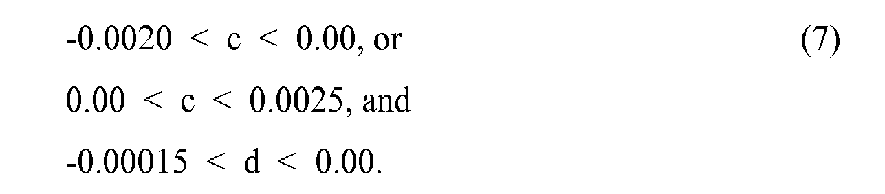
- It should be appreciated that ranges of values for the scalar "a" and coefficients "b", "c", and "d" are a subset of an infinite number of possible solutions for the polynomial equation (3). That is, the particular set of ranges provided above have been determined ) from an infinite number of possibilities to generate a family of curves (i.e., the curved surface section 104) that provide a gradual transitioning of the
condyle surface 100 from the radius of curvature R1 to the radius of curvature R2 such that anterior translation of thefemoral component 12 relative to thetibial bearing 14 is reduced or delayed. Additionally, it should be appreciated that the range of values for each coefficient "a", 'b", "c", and "d" are provided above in regard to embodiments designed using the metric system of units. - The overall shape of the
curved surface section 104 is also affected by the placement of the common origin O of the plurality ofrays 120. By limiting thedistance 124 between the common origin O of the plurality ofrays 120 and theorigin 122 of the radius of curvature R1, which defines the early flexion curvedsurface section 102, paradoxical anterior sliding of thefemoral component 12 on thetibial bearing 14 may be reduced or delayed. As such, in one embodiment, the location of the common origin O of the plurality ofrays 120 is selected such that thedistance 124 between the common origin O and theorigin 120 of the radius of curvature R1 is less than about 10 mm. - The
distance 124 between the common origin O and theorigin 122 of the radius of curvature R1 and the particular coefficient values may be dependent upon the particular size of thefemoral component 12 in some embodiments. For example, as shown inFIG. 12 , a table 700 illustrates one particular embodiment of coefficient values for the above-defined polynomial equation (3) and values for thedistance 124 defined between the common origin O and theorigin 122 of the radius of curvature R1. As shown in table 700, thedistance 124 between the common origin O and theorigin 122 of the radius of curvature R1 and the value for the scalar "a" change across the femoral component sizes. However, in this particular embodiment, the values for the coefficients "b", "c", and "d" are constant across the femoral component sizes. It should be appreciated, however, that in other embodiments, the coefficient values "b", "c", and "d" may change across the femoral component sizes. - The overall shape and design of the
condyle surface 100 of thefemoral component 12 has been described above in regard to asingle condyle femoral component 12. It should be appreciated that in some embodiments bothcondyles femoral component 12 may be symmetrical and have similar condyle surfaces 100. However, in other embodiments, thecondyles femoral component 12 may be asymmetrical. For example, as shown inFIG. 13 , thefemoral component 12 may include asecond condyle condyle surface 800, which is defined in part by a plurality ofcurved surface sections curved surface sections condyle surface 100, each of thecurved surface sections condyle surface 800. Additionally, thecurved surface section 802 is defined by a radius of curvature R5, which is gradually transitioned to a radius of curvature R6 via thecurved surface section 804. Similar to thecurved surface section 104, thecurved surface section 804 is defined by a plurality of rays 820, which originate from a common origin O1. Additionally, thecurved surface section 806 is defined by a radius of curvature R7 and thecurved surface section 808 is defined by a radius of curvature R8. - As such, in embodiments in which the
condyles curved surface sections 202, 802 extend between degrees of flexion that are approximately equal (i.e., each of thecurved surface section 202, 802 may extend from a approximately equal earlier degree of flexion to a substantially equal later degree of flexion). Similarly, thecurved surface sections 204, 804 extend between degrees of flexion that are approximately equal, thecurved surface sections 206, 806 extend between degrees of flexion that are substantially equal, and thecurved surface sections 208, 808 extend between degrees of flexion that are approximately equal. Additionally, the radius of curvature R5 is approximately ally equal to the radius of curvature R1, the radius of curvature R6 is approximately equal to the radius of curvature R2, the radius of curvature R7 is approximately equal to the radius of curvature R3, and the radius of curvature R8 is approximately equal to the radius of curvature R4. Further, the set of coefficient values "a", b", "c", and/or "d" of the equation (4) described above are approximately similar for both condyles. - However, in other embodiments, the
condyles curved surface sections 202, 802 may extend between different degrees of flexion. Thecurved surface sections 204, 804 may extend between different degrees of flexion. Thecurved surface sections 206, 806 may extend between different degrees of flexion. The curved surface sections 207, 807 may extend between different degrees of flexion. - Additionally, in those embodiments in which the
condyles
Claims (15)
- An orthopaedic knee prosthesis comprising:a femoral component having a condyle surface curved in the sagittal plane; anda tibial bearing having a bearing surface configured to articulate with the condyle surface of the femoral component,in which the condyle surface (i) contacts the bearing surface at a first contact point on the condyle surface at a first degree of flexion, the first degree of flexion being less than about 30° and (ii) contacts the bearing surface at a second contact point on the condyle surface at a second degree of flexion, the second degree of flexion being greater than about 45°,
in which (i) the condyle surface in the sagittal plane has a first radius of curvature at the first contact point, (ii) the condyle surface in the sagittal plane has a second radius of curvature at the second contact point, and (iii) the ratio of the first radius of curvature to the second radius of curvature is in the range of 1.10 to 1.45. - The orthopaedic knee prosthesis of claim 1, in which ratio of the first radius of curvature to the second radius of curvature is about 1.35.
- The orthopaedic knee prosthesis of claim 1, in which the first degree of flexion is in the range of 0° to 10°, preferably about 5°, and the second degree of flexion is in the range of 60° to 70°, preferably about 65°.
- The orthopaedic knee prosthesis of claim 1, in which:(i) the condyle surface contacts the bearing surface at a third contact point on the condyle surface at a third degree of flexion, the third degree of flexion being greater than the second degree of flexion, and(ii) the condyle surface in the sagittal plane has a third radius of curvature at the third contact point, the third radius of curvature being greater than the second radius of curvature by at least 0.5 mm.
- The orthopaedic knee prosthesis of claim 4, in which the ratio of the first radius of curvature to the third radius of curvature is in the range of 1.10 to 1.45, preferably about 1.28.
- The orthopaedic knee prosthesis of claim 4, in which the third degree of flexion is in the range of 80° to 110°, preferably about 90°.
- The orthopaedic knee prosthesis of claim 4, in which:(i) the condyle surface contacts the bearing surface at a fourth contact point on the condyle surface at a fourth degree of flexion, the fourth degree of flexion being greater than the third degree of flexion, and(ii) the condyle surface in the sagittal plane has a fourth radius of curvature at the fourth contact point, the fourth radius of curvature being less than the third radius of curvature.
- The orthopaedic knee prosthesis of claim 7, in which the ratio of the first radius of curvature to the fourth radius of curvature is in the range of 1.10 to 1.45, preferably about 1.305.
- The orthopaedic knee prosthesis of claim 7, in which the fourth degree of flexion is in the range of 90° to 120°, preferably about 105°.
- The orthopaedic knee prosthesis of claim 7, in which the ratio of the first radius of curvature to the second radius of curvature is about 1.35, the ratio of the first radius of curvature to the third radius of curvature is about 1.28, and the ratio of the first radius of curvature to the third radius of curvature is about 1.305.
- The orthopaedic knee prosthesis of claim 7, in which:the condyle surface of the femoral component in the sagittal plane includes (i) a first curved surface section defined between the second contact point and the third contact point and (ii) a second curved surface section defined between the third contact point and the fourth contact point,the first curved surface section having a substantially constant radius of curvature substantially equal to the third radius of curvature, andthe second curved surface section having a substantially constant radius of curvature substantially equal to the fourth radius of curvature.
- The orthopaedic knee prosthesis of claim 1, in which:the second degree of flexion is in the range of 45° to 90°,the condyle surface contacts the bearing surface at a plurality of contact points between the first contact point and the second contact point when the femoral component is moved from the first degree of flexion to the second degree of flexion, andeach contact point of the plurality of contact points is defined by a ray extending from a common origin to the respective contact point of the plurality of contact points, each ray having a length defined by the following polynomial equation:in which r θ is the length of the ray defining a contact point at θ degrees of flexion, a is a coefficient value between 20 and 50, and b is a coefficient value in a range selected from the group consisting of: -0.30 < b < 0.00, 0.00 < b < 0.30, and b = 0,

in which when b is in the range of-0.30 < b < 0.00, (i) c is a coefficient value between 0.00 and 0.012 and (ii) d is a coefficient value between -0.00015 and 0.00,
in which when b is in the range of 0 < b < 0.30, (i) c is a coefficient value between -0.010 and 0.00 and (ii) d is a coefficient value between -0.00015 and 0.00, and
in which when b is equal to 0, (i) c is a coefficient value in a range selected from the group consisting of: -0.0020 < c < 0.00 and 0.00 < c < 0.0025 and (ii) d is a coefficient value between -0.00015 and 0.00. - The orthopaedic knee prosthesis of claim 12, in which:the first radius of curvature has an origin, andthe distance between the origin of the first radius of curvature and the common origin of the rays is in the range of 0 and 10 mm.
- The orthopaedic knee prosthesis of claim 1, in which the femoral component is a posterior cruciate-retaining femoral component.
- An orthopaedic knee prosthesis comprising:a femoral component having a condyle surface curved in the sagittal plane; anda tibial bearing having a bearing surface configured to articulate with the condyle surface of the femoral component,in which the condyle surface (i) contacts the bearing surface at a first contact point on the condyle surface at a first degree of flexion, the first degree of flexion being less than about 30°, (ii) contacts the bearing surface at a second contact point on the condyle surface at a second degree of flexion, the second degree of flexion being in the range of 45° to 90°, and (iii) contacts the bearing surface at a plurality of contact points between the first contact point and the second contact point when the femoral component is moved from the first degree of flexion to the second degree of flexion,
in which each contact point of the plurality of contact points is defined by a ray extending from a common origin to the respective contact point of the plurality of contact points, each ray having a length defined by the following polynomial equation:
in which r θ is the length of the ray defining a contact point at θ degrees of flexion, a is a coefficient value between 20 and 50, and b is a coefficient value in a range selected from the group consisting of: -0.30 < b < 0.00, 0.00 < b < 0.30, and b = 0,
in which when b is in the range of -0.30 < b < 0.00, (i) c is a coefficient value between 0.00 and 0.012 and (ii) d is a coefficient value between -0.00015 and 0.00,
in which when b is in the range of 0 < b < 0.30, (i) c is a coefficient value between -0.010 and 0.00 and (ii) d is a coefficient value between -0.00015 and 0.00, and
in which when b is equal to 0, (i) c is a coefficient value in a range selected from the group consisting of: -0.0020 < c < 0.00 and 0.00 < c < 0.0025 and (ii) d is a coefficient value between -0.00015 and 0.00.
Priority Applications (2)
| Application Number | Priority Date | Filing Date | Title |
|---|---|---|---|
| EP10174439.9A EP2275053B1 (en) | 2008-06-30 | 2009-06-30 | Orthopaedic knee prosthesis |
| EP10174440.7A EP2275054B1 (en) | 2008-06-30 | 2009-06-30 | Orthopaedic knee prosthesis |
Applications Claiming Priority (1)
| Application Number | Priority Date | Filing Date | Title |
|---|---|---|---|
| US12/165,574 US8192498B2 (en) | 2008-06-30 | 2008-06-30 | Posterior cructiate-retaining orthopaedic knee prosthesis having controlled condylar curvature |
Related Child Applications (4)
| Application Number | Title | Priority Date | Filing Date |
|---|---|---|---|
| EP10174440.7A Division EP2275054B1 (en) | 2008-06-30 | 2009-06-30 | Orthopaedic knee prosthesis |
| EP10174440.7A Division-Into EP2275054B1 (en) | 2008-06-30 | 2009-06-30 | Orthopaedic knee prosthesis |
| EP10174439.9A Division EP2275053B1 (en) | 2008-06-30 | 2009-06-30 | Orthopaedic knee prosthesis |
| EP10174439.9A Division-Into EP2275053B1 (en) | 2008-06-30 | 2009-06-30 | Orthopaedic knee prosthesis |
Publications (2)
| Publication Number | Publication Date |
|---|---|
| EP2147660A1 true EP2147660A1 (en) | 2010-01-27 |
| EP2147660B1 EP2147660B1 (en) | 2016-02-24 |
Family
ID=41396250
Family Applications (3)
| Application Number | Title | Priority Date | Filing Date |
|---|---|---|---|
| EP10174439.9A Active EP2275053B1 (en) | 2008-06-30 | 2009-06-30 | Orthopaedic knee prosthesis |
| EP09164235.5A Active EP2147660B1 (en) | 2008-06-30 | 2009-06-30 | Orthopaedic knee prosthesis |
| EP10174440.7A Active EP2275054B1 (en) | 2008-06-30 | 2009-06-30 | Orthopaedic knee prosthesis |
Family Applications Before (1)
| Application Number | Title | Priority Date | Filing Date |
|---|---|---|---|
| EP10174439.9A Active EP2275053B1 (en) | 2008-06-30 | 2009-06-30 | Orthopaedic knee prosthesis |
Family Applications After (1)
| Application Number | Title | Priority Date | Filing Date |
|---|---|---|---|
| EP10174440.7A Active EP2275054B1 (en) | 2008-06-30 | 2009-06-30 | Orthopaedic knee prosthesis |
Country Status (6)
| Country | Link |
|---|---|
| US (3) | US8192498B2 (en) |
| EP (3) | EP2275053B1 (en) |
| JP (2) | JP5631561B2 (en) |
| CN (1) | CN101669844B (en) |
| AU (2) | AU2009202632B2 (en) |
| ES (3) | ES2570378T3 (en) |
Cited By (9)
| Publication number | Priority date | Publication date | Assignee | Title |
|---|---|---|---|---|
| US8551179B2 (en) | 2011-06-16 | 2013-10-08 | Zimmer, Inc. | Femoral prosthesis system having provisional component with visual indicators |
| US8932365B2 (en) | 2011-06-16 | 2015-01-13 | Zimmer, Inc. | Femoral component for a knee prosthesis with improved articular characteristics |
| US9060868B2 (en) | 2011-06-16 | 2015-06-23 | Zimmer, Inc. | Femoral component for a knee prosthesis with bone compacting ridge |
| US9173744B2 (en) | 2010-09-10 | 2015-11-03 | Zimmer Gmbh | Femoral prosthesis with medialized patellar groove |
| US9308095B2 (en) | 2011-06-16 | 2016-04-12 | Zimmer, Inc. | Femoral component for a knee prosthesis with improved articular characteristics |
| US9592127B2 (en) | 2005-12-15 | 2017-03-14 | Zimmer, Inc. | Distal femoral knee prostheses |
| US9750612B2 (en) | 2005-06-15 | 2017-09-05 | P Tech, Llc | Methods and systems for providing gender specific pharmaceuticals |
| US10130375B2 (en) | 2014-07-31 | 2018-11-20 | Zimmer, Inc. | Instruments and methods in performing kinematically-aligned total knee arthroplasty |
| US10136997B2 (en) | 2015-09-29 | 2018-11-27 | Zimmer, Inc. | Tibial prosthesis for tibia with varus resection |
Families Citing this family (63)
| Publication number | Priority date | Publication date | Assignee | Title |
|---|---|---|---|---|
| US8771365B2 (en) | 2009-02-25 | 2014-07-08 | Conformis, Inc. | Patient-adapted and improved orthopedic implants, designs, and related tools |
| US8556983B2 (en) | 2001-05-25 | 2013-10-15 | Conformis, Inc. | Patient-adapted and improved orthopedic implants, designs and related tools |
| US8545569B2 (en) | 2001-05-25 | 2013-10-01 | Conformis, Inc. | Patient selectable knee arthroplasty devices |
| US9603711B2 (en) | 2001-05-25 | 2017-03-28 | Conformis, Inc. | Patient-adapted and improved articular implants, designs and related guide tools |
| US8480754B2 (en) * | 2001-05-25 | 2013-07-09 | Conformis, Inc. | Patient-adapted and improved articular implants, designs and related guide tools |
| US8882847B2 (en) | 2001-05-25 | 2014-11-11 | Conformis, Inc. | Patient selectable knee joint arthroplasty devices |
| US8735773B2 (en) | 2007-02-14 | 2014-05-27 | Conformis, Inc. | Implant device and method for manufacture |
| US6558426B1 (en) | 2000-11-28 | 2003-05-06 | Medidea, Llc | Multiple-cam, posterior-stabilized knee prosthesis |
| EP1389980B1 (en) | 2001-05-25 | 2011-04-06 | Conformis, Inc. | Methods and compositions for articular resurfacing |
| US9308091B2 (en) | 2001-05-25 | 2016-04-12 | Conformis, Inc. | Devices and methods for treatment of facet and other joints |
| EP1555962B1 (en) | 2002-10-07 | 2011-02-09 | Conformis, Inc. | Minimally invasive joint implant with 3-dimensional geometry matching the articular surfaces |
| AU2003290757A1 (en) | 2002-11-07 | 2004-06-03 | Conformis, Inc. | Methods for determing meniscal size and shape and for devising treatment |
| WO2005037147A1 (en) | 2003-10-17 | 2005-04-28 | Smith & Nephew, Inc. | High flexion articular insert |
| US8308812B2 (en) | 2006-11-07 | 2012-11-13 | Biomedflex, Llc | Prosthetic joint assembly and joint member therefor |
| US20110166671A1 (en) | 2006-11-07 | 2011-07-07 | Kellar Franz W | Prosthetic joint |
| US9005306B2 (en) | 2006-11-07 | 2015-04-14 | Biomedflex, Llc | Medical Implants With Compliant Wear-Resistant Surfaces |
| US8070823B2 (en) | 2006-11-07 | 2011-12-06 | Biomedflex Llc | Prosthetic ball-and-socket joint |
| US8029574B2 (en) | 2006-11-07 | 2011-10-04 | Biomedflex Llc | Prosthetic knee joint |
| US8512413B2 (en) | 2006-11-07 | 2013-08-20 | Biomedflex, Llc | Prosthetic knee joint |
| US9005307B2 (en) | 2006-11-07 | 2015-04-14 | Biomedflex, Llc | Prosthetic ball-and-socket joint |
| EP2114312B1 (en) | 2007-02-14 | 2014-01-08 | ConforMIS, Inc. | Method for manufacture of an implant device |
| US8632600B2 (en) | 2007-09-25 | 2014-01-21 | Depuy (Ireland) | Prosthesis with modular extensions |
| US8128703B2 (en) | 2007-09-28 | 2012-03-06 | Depuy Products, Inc. | Fixed-bearing knee prosthesis having interchangeable components |
| US9204967B2 (en) | 2007-09-28 | 2015-12-08 | Depuy (Ireland) | Fixed-bearing knee prosthesis having interchangeable components |
| EP2901969B1 (en) * | 2008-03-05 | 2018-07-04 | ConforMIS, Inc. | Method of making an edge-matched articular implant |
| US8682052B2 (en) | 2008-03-05 | 2014-03-25 | Conformis, Inc. | Implants for altering wear patterns of articular surfaces |
| US9119723B2 (en) | 2008-06-30 | 2015-09-01 | Depuy (Ireland) | Posterior stabilized orthopaedic prosthesis assembly |
| US8206451B2 (en) | 2008-06-30 | 2012-06-26 | Depuy Products, Inc. | Posterior stabilized orthopaedic prosthesis |
| US8236061B2 (en) | 2008-06-30 | 2012-08-07 | Depuy Products, Inc. | Orthopaedic knee prosthesis having controlled condylar curvature |
| US8828086B2 (en) | 2008-06-30 | 2014-09-09 | Depuy (Ireland) | Orthopaedic femoral component having controlled condylar curvature |
| US8192498B2 (en) | 2008-06-30 | 2012-06-05 | Depuy Products, Inc. | Posterior cructiate-retaining orthopaedic knee prosthesis having controlled condylar curvature |
| US9168145B2 (en) | 2008-06-30 | 2015-10-27 | Depuy (Ireland) | Posterior stabilized orthopaedic knee prosthesis having controlled condylar curvature |
| US8187335B2 (en) | 2008-06-30 | 2012-05-29 | Depuy Products, Inc. | Posterior stabilized orthopaedic knee prosthesis having controlled condylar curvature |
| US8078440B2 (en) * | 2008-09-19 | 2011-12-13 | Smith & Nephew, Inc. | Operatively tuning implants for increased performance |
| US9615929B2 (en) * | 2009-01-23 | 2017-04-11 | Zimmer, Inc. | Posterior-stabilized total knee prosthesis |
| EP2405865B1 (en) | 2009-02-24 | 2019-04-17 | ConforMIS, Inc. | Automated systems for manufacturing patient-specific orthopedic implants and instrumentation |
| US8915965B2 (en) * | 2009-05-07 | 2014-12-23 | Depuy (Ireland) | Anterior stabilized knee implant |
| US11213397B2 (en) | 2009-05-21 | 2022-01-04 | Depuy Ireland Unlimited Company | Prosthesis with surfaces having different textures and method of making the prosthesis |
| US9101476B2 (en) | 2009-05-21 | 2015-08-11 | Depuy (Ireland) | Prosthesis with surfaces having different textures and method of making the prosthesis |
| EP2272466A1 (en) * | 2009-07-10 | 2011-01-12 | Medizinische Hochschule Hannover | Knee joint prosthesis and method for producing said prosthesis |
| US10307256B2 (en) * | 2009-07-27 | 2019-06-04 | Biomet Manufacturing, Llc | Knee replacement system and method for enabling natural knee movement |
| CA2782137A1 (en) | 2009-12-11 | 2011-06-16 | Conformis, Inc. | Patient-specific and patient-engineered orthopedic implants |
| US9011547B2 (en) | 2010-01-21 | 2015-04-21 | Depuy (Ireland) | Knee prosthesis system |
| CN102821717B (en) | 2010-01-29 | 2016-01-20 | 史密夫和内修有限公司 | Cross maintenance knee prostheses |
| US9132014B2 (en) | 2010-04-13 | 2015-09-15 | Zimmer, Inc. | Anterior cruciate ligament substituting knee implants |
| US8317870B2 (en) | 2010-09-30 | 2012-11-27 | Depuy Products, Inc. | Tibial component of a knee prosthesis having an angled cement pocket |
| US8287601B2 (en) | 2010-09-30 | 2012-10-16 | Depuy Products, Inc. | Femoral component of a knee prosthesis having an angled cement pocket |
| EP2754419B1 (en) | 2011-02-15 | 2024-02-07 | ConforMIS, Inc. | Patient-adapted and improved orthopedic implants |
| CN103796617B (en) * | 2011-06-30 | 2016-08-24 | 德普伊(爱尔兰)有限公司 | There is posterior stabilized plastic surgery's knee-joint prosthesis of controlled condylar curvature |
| WO2013007747A1 (en) | 2011-07-13 | 2013-01-17 | Zimmer Gmbh | Femoral knee prosthesis with diverging lateral condyle |
| CN103655007B (en) * | 2012-08-31 | 2016-06-22 | 北京纳通科技集团有限公司 | Tibial base element and knee-joint prosthesis |
| US9237953B2 (en) | 2013-03-15 | 2016-01-19 | Depuy (Ireland) | Mechanical assembly of pegs to prosthesis |
| CA2906631C (en) | 2013-03-15 | 2018-05-01 | Robert Craig COHEN | Unicondylar tibial knee implant |
| US9144499B2 (en) | 2013-12-17 | 2015-09-29 | Depuy (Ireland) | Low profile mobile/fixed prosthetic knee systems |
| JP6470541B2 (en) * | 2014-10-21 | 2019-02-13 | 京セラ株式会社 | Total knee implant |
| CA3066766C (en) * | 2015-01-21 | 2021-09-14 | Active Implants LLC | Partial unicompartmental system for partial knee replacement |
| US10148759B2 (en) | 2016-04-04 | 2018-12-04 | Gogo Llc | Presence-based network authentication |
| US11406502B2 (en) | 2017-03-02 | 2022-08-09 | Optimotion Implants LLC | Orthopedic implants and methods |
| WO2019023476A1 (en) | 2017-07-26 | 2019-01-31 | Optimotion Implants LLC | Modular knee prosthesis, instruments, and methods |
| EP3730098A1 (en) * | 2019-04-22 | 2020-10-28 | Beijing Naton Medical Technology Research Institute Co., Ltd. | Femoral prosthesis and knee prosthesis |
| CN114072087A (en) | 2019-05-02 | 2022-02-18 | 德普伊爱尔兰无限公司 | Orthopaedic implant placement system and method |
| WO2021048236A2 (en) | 2019-09-10 | 2021-03-18 | Depuy Ireland Unlimited Company | Orthopaedic knee prosthesis system and methods for using same |
| WO2022008755A2 (en) | 2020-07-10 | 2022-01-13 | Depuy Ireland Unlimited Company | Medial stabilized orthopaedic knee prosthesis |
Citations (4)
| Publication number | Priority date | Publication date | Assignee | Title |
|---|---|---|---|---|
| WO1979000739A1 (en) * | 1978-03-10 | 1979-10-04 | Biomedical Eng Corp | Improved joint endoprosthesis |
| US6013103A (en) * | 1996-07-11 | 2000-01-11 | Wright Medical Technology, Inc. | Medial pivot knee prosthesis |
| EP1129676A1 (en) * | 2000-02-24 | 2001-09-05 | Aesculap | Femoral piece of a knee prosthesis with three radii of curvature |
| US7712408B1 (en) | 2007-08-10 | 2010-05-11 | Pro-Tecks, L.L.C. | Methods and apparatus for personal safety |
Family Cites Families (337)
| Publication number | Priority date | Publication date | Assignee | Title |
|---|---|---|---|---|
| GB1065354A (en) | 1964-04-13 | 1967-04-12 | Gen Electric | Improvements in fortification of anodized surfaces |
| CA962806A (en) | 1970-06-04 | 1975-02-18 | Ontario Research Foundation | Surgical prosthetic device |
| US3765033A (en) * | 1971-01-19 | 1973-10-16 | D Goldberg | Prosthetic knee joint assembly with mutually slidable and rollable joint sections |
| US3852045A (en) | 1972-08-14 | 1974-12-03 | Battelle Memorial Institute | Void metal composite material and method |
| GB1448818A (en) | 1972-09-18 | 1976-09-08 | Nat Res Dev | Prosthetic knee joint devices |
| US3869731A (en) | 1973-02-14 | 1975-03-11 | Univ California | Articulated two-part prosthesis replacing the knee joint |
| GB1550010A (en) | 1976-12-15 | 1979-08-08 | Ontario Research Foundation | Surgical prosthetic device or implant having pure metal porous coating |
| US4081866A (en) | 1977-02-02 | 1978-04-04 | Howmedica, Inc. | Total anatomical knee prosthesis |
| US4156943A (en) | 1977-08-24 | 1979-06-05 | Collier John P | High-strength porous prosthetic device and process for making the same |
| US4209861A (en) | 1978-02-22 | 1980-07-01 | Howmedica, Inc. | Joint prosthesis |
| US4470158A (en) | 1978-03-10 | 1984-09-11 | Biomedical Engineering Corp. | Joint endoprosthesis |
| CH632151A5 (en) | 1978-10-06 | 1982-09-30 | Sulzer Ag | ENDOPROTHESIS FOR A KNEE JOINT. |
| US4215439A (en) | 1978-10-16 | 1980-08-05 | Zimmer, USA | Semi-restraining knee prosthesis |
| US4257129A (en) | 1979-05-21 | 1981-03-24 | Volz Robert G | Prosthetic knee joint tibial implant |
| US4340978A (en) | 1979-07-02 | 1982-07-27 | Biomedical Engineering Corp. | New Jersey meniscal bearing knee replacement |
| US4262368A (en) * | 1979-09-24 | 1981-04-21 | Wright Manufacturing Company | Rotating and hinged knee prosthesis |
| US5037423A (en) | 1983-10-26 | 1991-08-06 | Pfizer Hospital Products Group, Inc. | Method and instrumentation for the replacement of a knee prosthesis |
| US4944760A (en) | 1983-10-26 | 1990-07-31 | Pfizer Hospital Products Group, Inc. | Method and instrumentation for the replacement of a knee prosthesis |
| US4612160A (en) | 1984-04-02 | 1986-09-16 | Dynamet, Inc. | Porous metal coating process and mold therefor |
| SE450336B (en) | 1984-11-28 | 1987-06-22 | Branemark Per Ingvar | LED PROTES FOR PERMANENT ANCHORING IN THE BONE TISSUE |
| US4673407A (en) | 1985-02-20 | 1987-06-16 | Martin Daniel L | Joint-replacement prosthetic device |
| US5201766A (en) | 1985-09-11 | 1993-04-13 | Smith & Nephew Richards Inc. | Prosthetic device with porous matrix and method of manufacture |
| US4808185A (en) | 1986-02-07 | 1989-02-28 | Penenberg Brad L | Tibial prosthesis, template and reamer |
| JPS62205201A (en) | 1986-03-06 | 1987-09-09 | Nippon Kokan Kk <Nkk> | Sealing treatment of sintered body |
| US4714474A (en) | 1986-05-12 | 1987-12-22 | Dow Corning Wright Corporation | Tibial knee joint prosthesis with removable articulating surface insert |
| US4963152A (en) | 1986-10-27 | 1990-10-16 | Intermedics Orthopedics, Inc. | Asymmetric prosthetic tibial component |
| US4822362A (en) | 1987-05-19 | 1989-04-18 | Walker Peter S | Process and apparatus for tibial plateau compenent |
| FR2621243A1 (en) | 1987-10-06 | 1989-04-07 | Cuilleron J | Total knee prothesis |
| US4795468A (en) | 1987-12-23 | 1989-01-03 | Zimmer, Inc. | Mechanism and method for locking a bearing insert to the base of a prosthetic implant |
| US5011496A (en) | 1988-02-02 | 1991-04-30 | Joint Medical Products Corporation | Prosthetic joint |
| US4888021A (en) | 1988-02-02 | 1989-12-19 | Joint Medical Products Corporation | Knee and patellar prosthesis |
| US4950298A (en) | 1988-04-08 | 1990-08-21 | Gustilo Ramon B | Modular knee joint prosthesis |
| US4944757A (en) | 1988-11-07 | 1990-07-31 | Martinez David M | Modulator knee prosthesis system |
| US5007933A (en) | 1989-01-31 | 1991-04-16 | Osteonics Corp. | Modular knee prosthesis system |
| US4990163A (en) | 1989-02-06 | 1991-02-05 | Trustees Of The University Of Pennsylvania | Method of depositing calcium phosphate cermamics for bone tissue calcification enhancement |
| US4938769A (en) | 1989-05-31 | 1990-07-03 | Shaw James A | Modular tibial prosthesis |
| GB8912682D0 (en) | 1989-06-02 | 1989-07-19 | Thackray Chas F | Improvements in and relating to knee prosthesis |
| US5171283A (en) | 1989-07-11 | 1992-12-15 | Biomedical Engineering Trust | Compound shape rotating bearing |
| FR2653992B1 (en) | 1989-11-09 | 1998-01-23 | Richard Berakassa | TOTAL SLIDING KNEE PROSTHESIS. |
| US5019103A (en) | 1990-02-05 | 1991-05-28 | Boehringer Mannheim Corporation | Tibial wedge system |
| US5147405A (en) | 1990-02-07 | 1992-09-15 | Boehringer Mannheim Corporation | Knee prosthesis |
| GB9005496D0 (en) | 1990-03-12 | 1990-05-09 | Howmedica | Tibial component for a replacement knee prosthesis and total knee prosthesis incorporating such a component |
| US5358531A (en) | 1990-06-12 | 1994-10-25 | British Technology Group Limited | Prosthetic knee joint devices |
| US5116375A (en) | 1990-08-27 | 1992-05-26 | Hofmann Aaron A | Knee prosthesis |
| US5104410A (en) | 1990-10-22 | 1992-04-14 | Intermedics Orthopedics, Inc | Surgical implant having multiple layers of sintered porous coating and method |
| US5071438A (en) | 1990-11-07 | 1991-12-10 | Intermedics Orthopedics, Inc. | Tibial prothesis with pivoting articulating surface |
| CA2078228C (en) | 1990-11-14 | 2000-04-11 | Lawrence Pottenger | Improved floating bearing prosthetic knee |
| EP0495340A1 (en) | 1991-01-18 | 1992-07-22 | Gebrüder Sulzer Aktiengesellschaft | Modular construction kit for the tibial part of a knee joint prosthesis |
| US5609639A (en) | 1991-02-04 | 1997-03-11 | Walker; Peter S. | Prosthesis for knee replacement |
| GB9314839D0 (en) | 1993-07-16 | 1993-09-01 | Walker Peter S | Prosthesis for knee replacement |
| GB9102348D0 (en) | 1991-02-04 | 1991-03-20 | Inst Of Orthopaedics The | Prosthesis for knee replacement |
| GB9102633D0 (en) | 1991-02-07 | 1991-03-27 | Finsbury Instr Ltd | Knee prosthesis |
| US5358527A (en) | 1991-03-22 | 1994-10-25 | Forte Mark R | Total knee prosthesis with resurfacing and posterior stabilization capability |
| US5236461A (en) | 1991-03-22 | 1993-08-17 | Forte Mark R | Totally posterior stabilized knee prosthesis |
| US5108442A (en) | 1991-05-09 | 1992-04-28 | Boehringer Mannheim Corporation | Prosthetic implant locking assembly |
| US5395401A (en) | 1991-06-17 | 1995-03-07 | Bahler; Andre | Prosthetic device for a complex joint |
| US5133758A (en) | 1991-09-16 | 1992-07-28 | Research And Education Institute, Inc. Harbor-Ucla Medical Center | Total knee endoprosthesis with fixed flexion-extension axis of rotation |
| US5258044A (en) | 1992-01-30 | 1993-11-02 | Etex Corporation | Electrophoretic deposition of calcium phosphate material on implants |
| US5330534A (en) | 1992-02-10 | 1994-07-19 | Biomet, Inc. | Knee joint prosthesis with interchangeable components |
| US5236457A (en) | 1992-02-27 | 1993-08-17 | Zimmer, Inc. | Method of making an implant having a metallic porous surface |
| US5282861A (en) | 1992-03-11 | 1994-02-01 | Ultramet | Open cell tantalum structures for cancellous bone implants and cell and tissue receptors |
| US5496372A (en) | 1992-04-17 | 1996-03-05 | Kyocera Corporation | Hard tissue prosthesis including porous thin metal sheets |
| NZ243181A (en) | 1992-04-23 | 1994-10-26 | Michael John Pappas | Prosthetic joint with guide means to limit articulation of a first element and bearing means to two degrees of freedom |
| US5824102A (en) | 1992-06-19 | 1998-10-20 | Buscayret; Christian | Total knee prosthesis |
| US5271737A (en) | 1992-09-04 | 1993-12-21 | U.S. Medical Products, Inc. | Tibial prosthetic implant with offset stem |
| US5344460A (en) | 1992-10-30 | 1994-09-06 | Encore Orthopedics, Inc. | Prosthesis system |
| US5658342A (en) | 1992-11-16 | 1997-08-19 | Arch Development | Stabilized prosthetic knee |
| US5309639A (en) | 1992-11-23 | 1994-05-10 | The Timken Company | Method of making a machine component with lubricated wear surface |
| US5251468A (en) | 1992-12-14 | 1993-10-12 | Zimmer, Inc. | Method of surface finishing orthopaedic implant devices using a bioactive blasting medium |
| US5413604A (en) | 1992-12-24 | 1995-05-09 | Osteonics Corp. | Prosthetic knee implant for an anterior cruciate ligament deficient total knee replacement |
| US5344494A (en) | 1993-01-21 | 1994-09-06 | Smith & Nephew Richards, Inc. | Method for cleaning porous and roughened surfaces on medical implants |
| US5370699A (en) | 1993-01-21 | 1994-12-06 | Orthomet, Inc. | Modular knee joint prosthesis |
| US5344461A (en) | 1993-02-12 | 1994-09-06 | Zimmer, Inc. | Modular implant provisional |
| US5308556A (en) | 1993-02-23 | 1994-05-03 | Corning Incorporated | Method of making extrusion dies from powders |
| DE4308563A1 (en) | 1993-03-18 | 1994-09-22 | Alphanorm Medizintechnik Gmbh | Knee-joint prosthesis |
| US5414049A (en) | 1993-06-01 | 1995-05-09 | Howmedica Inc. | Non-oxidizing polymeric medical implant |
| US5368881A (en) | 1993-06-10 | 1994-11-29 | Depuy, Inc. | Prosthesis with highly convoluted surface |
| US5405396A (en) | 1993-07-01 | 1995-04-11 | Zimmer, Inc. | Tibial prosthesis |
| GB9314832D0 (en) | 1993-07-16 | 1993-09-01 | Walker Peter S | Prostheses for knee replacement |
| DE59408909D1 (en) | 1993-10-13 | 1999-12-16 | Ciba Sc Holding Ag | New fluorescent dyes |
| US5549686A (en) | 1994-06-06 | 1996-08-27 | Zimmer, Inc. | Knee prosthesis having a tapered cam |
| SE504971C2 (en) | 1994-07-11 | 1997-06-02 | Sandvik Ab | Saw blade with fluid injection |
| US5755803A (en) | 1994-09-02 | 1998-05-26 | Hudson Surgical Design | Prosthetic implant |
| GB9418492D0 (en) | 1994-09-14 | 1994-11-02 | Goodfellow John W | Prosthetic knee joint device |
| US5571194A (en) | 1994-11-14 | 1996-11-05 | Johnson & Johnson Professional, Inc. | Femoral augmentation system for artificial knee joint |
| US5458637A (en) | 1994-11-21 | 1995-10-17 | Zimmer, Inc. | Orthopaedic base component with modular augmentation block |
| US5702458A (en) | 1994-12-09 | 1997-12-30 | New York Society For The Ruptured And Crippled Maintaining The Hospital For Special Surgery | Joint prosthesis |
| US5824096A (en) | 1994-12-12 | 1998-10-20 | Biomedical Engineering Trust I | Hinged knee prosthesis with condylar bearing |
| CA2166450C (en) | 1995-01-20 | 2008-03-25 | Ronald Salovey | Chemically crosslinked ultrahigh molecular weight polyethylene for artificial human joints |
| AUPN089495A0 (en) | 1995-02-03 | 1995-03-02 | Denupo Pty. Ltd. | Knee prosthesis |
| US5639279A (en) | 1995-02-09 | 1997-06-17 | Intermedics Orthopedics, Inc. | Posteriorly-stabilized prosthetic knee |
| US5683468A (en) | 1995-03-13 | 1997-11-04 | Pappas; Michael J. | Mobile bearing total joint replacement |
| US5609643A (en) | 1995-03-13 | 1997-03-11 | Johnson & Johnson Professional, Inc. | Knee joint prosthesis |
| AU701181B2 (en) | 1995-06-01 | 1999-01-21 | Depuy Orthopaedics, Inc. | Augmentation device for joint prostheses |
| US5984969A (en) | 1995-06-01 | 1999-11-16 | Johnson & Johnson Professional, Inc. | Joint prosthesis augmentation system |
| DE19529824A1 (en) | 1995-08-14 | 1997-02-20 | Bodo Gnutzmann | Bi-condylar endoprosthesis for knee |
| US5871546A (en) * | 1995-09-29 | 1999-02-16 | Johnson & Johnson Professional, Inc. | Femoral component condyle design for knee prosthesis |
| US5776201A (en) | 1995-10-02 | 1998-07-07 | Johnson & Johnson Professional, Inc. | Modular femoral trial system |
| US5989027A (en) | 1995-12-08 | 1999-11-23 | Sulzer Calcitek Inc. | Dental implant having multiple textured surfaces |
| US5658344A (en) | 1995-12-29 | 1997-08-19 | Johnson & Johnson Professional, Inc. | Tibial insert reinforcement pin |
| US5843289A (en) | 1996-01-22 | 1998-12-01 | Etex Corporation | Surface modification of medical implants |
| US5879400A (en) | 1996-02-13 | 1999-03-09 | Massachusetts Institute Of Technology | Melt-irradiated ultra high molecular weight polyethylene prosthetic devices |
| US5681354A (en) | 1996-02-20 | 1997-10-28 | Board Of Regents, University Of Colorado | Asymmetrical femoral component for knee prosthesis |
| US5702463A (en) | 1996-02-20 | 1997-12-30 | Smith & Nephew Inc. | Tibial prosthesis with polymeric liner and liner insertion/removal instrument |
| US5702464A (en) | 1996-02-20 | 1997-12-30 | Smith & Nephew Inc. | Modular trial tibial insert |
| US5871543A (en) | 1996-02-23 | 1999-02-16 | Hofmann; Aaron A. | Tibial prosthesis with mobile bearing member |
| HU219444B (en) | 1996-02-26 | 2001-04-28 | Gábor Krakovits | Sliding surface for knee-joint prothesis |
| GB9611059D0 (en) | 1996-05-28 | 1996-07-31 | Howmedica | Tibial element for a replacement knee prosthesis |
| US6228900B1 (en) | 1996-07-09 | 2001-05-08 | The Orthopaedic Hospital And University Of Southern California | Crosslinking of polyethylene for low wear using radiation and thermal treatments |
| US5765095A (en) | 1996-08-19 | 1998-06-09 | Smith International, Inc. | Polycrystalline diamond bit manufacturing |
| US5906644A (en) | 1996-08-30 | 1999-05-25 | Powell; Douglas Hunter | Adjustable modular orthopedic implant |
| DK0927010T3 (en) | 1996-09-11 | 2003-02-10 | Plus Endoprothetik Ag | Tibia part of a knee joint endoprosthesis |
| US6004351A (en) | 1996-09-14 | 1999-12-21 | Mizuho Ika Kogyo Kabushiki Kaisha | Prosthetic knee joint |
| US6017975A (en) | 1996-10-02 | 2000-01-25 | Saum; Kenneth Ashley | Process for medical implant of cross-linked ultrahigh molecular weight polyethylene having improved balance of wear properties and oxidation resistance |
| US5824100A (en) | 1996-10-30 | 1998-10-20 | Osteonics Corp. | Knee prosthesis with increased balance and reduced bearing stress |
| US5755800A (en) | 1996-12-23 | 1998-05-26 | Johnson & Johnson Professional, Inc. | Modular joint prosthesis augmentation system |
| US5766257A (en) | 1997-01-28 | 1998-06-16 | Implant Manufacturing And Testing Corporation | Artificial joint having natural load transfer |
| GB2323034B (en) | 1997-03-13 | 2001-07-25 | Zimmer Ltd | Prosthesis for knee replacement |
| US6210612B1 (en) | 1997-03-31 | 2001-04-03 | Pouvair Corporation | Method for the manufacture of porous ceramic articles |
| GB9707717D0 (en) | 1997-04-16 | 1997-06-04 | Walker Peter S | Knee prosthesis having guide surfaces for control of anterior-posterior translation |
| US6059949A (en) | 1997-04-23 | 2000-05-09 | Cerel (Ceramic Technologies) Ltd. | Method of electrophoretic deposition of ceramic bodies for use in manufacturing dental appliances |
| US5824103A (en) | 1997-05-12 | 1998-10-20 | Howmedica Inc. | Tibial prosthesis |
| US6139581A (en) | 1997-06-06 | 2000-10-31 | Depuy Orthopaedics, Inc. | Posterior compensation tibial tray |
| US5976147A (en) | 1997-07-11 | 1999-11-02 | Johnson & Johnson Professional, Inc | Modular instrumentation for bone preparation and implant trial reduction of orthopedic implants |
| US6039764A (en) | 1997-08-18 | 2000-03-21 | Arch Development Corporation | Prosthetic knee with adjusted center of internal/external rotation |
| US6123728A (en) | 1997-09-17 | 2000-09-26 | Smith & Nephew, Inc. | Mobile bearing knee prosthesis |
| FR2768613B1 (en) | 1997-09-23 | 1999-12-17 | Tornier Sa | KNEE PROSTHESIS WITH ROTATABLE PLATFORM |
| US6053945A (en) | 1997-09-25 | 2000-04-25 | Johnson & Johnson Professional, Inc. | Joint prosthesis having controlled rotation |
| US6010534A (en) | 1997-09-25 | 2000-01-04 | Johnson & Johnson Professional, Inc. | Rotatable tibial prosthesis with keyed axial securement |
| US5951603A (en) | 1997-09-25 | 1999-09-14 | Johnson & Johnson Professional, Inc. | Rotatable joint prosthesis with axial securement |
| US6206926B1 (en) | 1997-10-06 | 2001-03-27 | Biomedical Engineering Trust I | Prosthetic knee joint with enhanced posterior stabilization and dislocation prevention features |
| FR2769495B1 (en) | 1997-10-14 | 1999-12-31 | Michel Timoteo | KNEE PROSTHESIS |
| US6325828B1 (en) | 1997-12-02 | 2001-12-04 | Rose Biomedical Research | Apparatus for knee prosthesis |
| FR2772259B1 (en) | 1997-12-12 | 2000-03-03 | Tornier Sa | IMPROVEMENTS IN TOTAL KNEE PROSTHESES COMPRISING A FEMORAL ELEMENT AND A TIBIAL PLATE |
| US5957979A (en) | 1997-12-12 | 1999-09-28 | Bristol-Myers Squibb Company | Mobile bearing knee with metal on metal interface |
| US6135857A (en) | 1998-03-02 | 2000-10-24 | General Electric Company | Method for surface enhancement by fluid jet impact |
| US6123729A (en) | 1998-03-10 | 2000-09-26 | Bristol-Myers Squibb Company | Four compartment knee |
| US6090144A (en) | 1998-05-12 | 2000-07-18 | Letot; Patrick | Synthetic knee system |
| DE69918894T2 (en) | 1998-05-13 | 2005-08-11 | Depuy Products, Inc., Warsaw | Tibial platform with adjustable shaft |
| US6660039B1 (en) | 1998-05-20 | 2003-12-09 | Smith & Nephew, Inc. | Mobile bearing knee prosthesis |
| US6428577B1 (en) | 1998-05-20 | 2002-08-06 | Smith & Nephew, Inc. | Mobile bearing knee prosthesis |
| US6126692A (en) | 1998-06-25 | 2000-10-03 | New York Society For The Relief Of The Ruptured And Crippled Maintaining The Hospital For Special Surgery | Retaining mechanism for a modular tibial component of a knee prosthesis |
| FR2780636B1 (en) | 1998-07-06 | 2000-10-06 | Merck Biomaterial France | MODULAR KNEE PROSTHESIS |
| US6080195A (en) | 1998-07-08 | 2000-06-27 | Johnson & Johnson Professional, Inc. | Rotatable and translatable joint prosthesis with posterior stabilization |
| CA2279660C (en) | 1998-08-05 | 2004-02-24 | Biomedical Engineering Trust I | Knee joint prosthesis with spinout prevention |
| US6443991B1 (en) | 1998-09-21 | 2002-09-03 | Depuy Orthopaedics, Inc. | Posterior stabilized mobile bearing knee |
| US6152960A (en) | 1998-10-13 | 2000-11-28 | Biomedical Engineering Trust I | Femoral component for knee endoprosthesis |
| US6500208B1 (en) | 1998-10-16 | 2002-12-31 | Biomet, Inc. | Nonmodular joint prosthesis convertible in vivo to a modular prosthesis |
| US6280476B1 (en) | 1998-10-16 | 2001-08-28 | Biomet Inc. | Hip joint prosthesis convertible in vivo to a modular prosthesis |
| FR2787012A1 (en) | 1998-12-11 | 2000-06-16 | Bex Anne Marie | Knee joint endoprosthesis has two cylinders projecting from underside of tibial component for partial or complete joint replacement |
| US6042780A (en) | 1998-12-15 | 2000-03-28 | Huang; Xiaodi | Method for manufacturing high performance components |
| US6623526B1 (en) | 1999-01-08 | 2003-09-23 | Corin Limited | Knee prosthesis |
| US6123896A (en) | 1999-01-29 | 2000-09-26 | Ceracon, Inc. | Texture free ballistic grade tantalum product and production method |
| US6361564B1 (en) | 1999-02-02 | 2002-03-26 | Aesculap | Total knee joint comprising an insert movable relative to a tenon |
| US6972039B2 (en) | 1999-03-01 | 2005-12-06 | Biomet, Inc. | Floating bearing knee joint prosthesis with a fixed tibial post |
| US7341602B2 (en) | 1999-05-10 | 2008-03-11 | Fell Barry M | Proportioned surgically implantable knee prosthesis |
| US6245276B1 (en) | 1999-06-08 | 2001-06-12 | Depuy Orthopaedics, Inc. | Method for molding a cross-linked preform |
| US6319283B1 (en) | 1999-07-02 | 2001-11-20 | Bristol-Myers Squibb Company | Tibial knee component with a mobile bearing |
| FR2796836B1 (en) | 1999-07-26 | 2002-03-22 | Michel Bercovy | NEW KNEE PROSTHESIS |
| KR100626409B1 (en) | 1999-09-14 | 2006-09-20 | 스트라테크 메디칼 아게 | Mixture of two particulate phases used in the production of a green compact that can be sintered at higher temperatures and production methoth of bodies using the two particulate phases |
| US6620198B2 (en) | 1999-10-07 | 2003-09-16 | Exactech, Inc. | Composite bearing inserts for total knee joints |
| US6217618B1 (en) | 1999-10-26 | 2001-04-17 | Bristol-Myers Squibb Company | Tibial knee component with a mobile bearing |
| US6210445B1 (en) | 1999-10-26 | 2001-04-03 | Bristol-Myers Squibb Company | Tibial knee component with a mobile bearing |
| US6210444B1 (en) | 1999-10-26 | 2001-04-03 | Bristol-Myers Squibb Company | Tibial knee component with a mobile bearing |
| US6379388B1 (en) | 1999-12-08 | 2002-04-30 | Ortho Development Corporation | Tibial prosthesis locking system and method of repairing knee joint |
| US6770078B2 (en) | 2000-01-14 | 2004-08-03 | Peter M. Bonutti | Movable knee implant and methods therefor |
| US7635390B1 (en) | 2000-01-14 | 2009-12-22 | Marctec, Llc | Joint replacement component having a modular articulating surface |
| US6702821B2 (en) | 2000-01-14 | 2004-03-09 | The Bonutti 2003 Trust A | Instrumentation for minimally invasive joint replacement and methods for using same |
| US7104996B2 (en) | 2000-01-14 | 2006-09-12 | Marctec. Llc | Method of performing surgery |
| US6491726B2 (en) | 2000-03-08 | 2002-12-10 | Biomedical Engineering Trust I | Posterior stabilized prosthetic knee replacement with bearing translation and dislocation prevention features |
| US6475241B2 (en) | 2000-03-13 | 2002-11-05 | Biomedical Engineering Trust I | Posterior stabilized knee replacement with bearing translation for knees with retained collateral ligaments |
| US8796347B2 (en) | 2000-04-27 | 2014-08-05 | Orthopaedic Hospital | Oxidation-resistant and wear-resistant polyethylenes for human joint replacements and methods for making them |
| US7618462B2 (en) | 2000-05-01 | 2009-11-17 | Arthrosurface Incorporated | System and method for joint resurface repair |
| US7678151B2 (en) | 2000-05-01 | 2010-03-16 | Ek Steven W | System and method for joint resurface repair |
| FR2809302B1 (en) | 2000-05-23 | 2003-03-21 | Didier Baert | ORTHOPEDIC IMPLANTS AND MORE PARTICULARLY KNEE PROSTHESES |
| GB0017148D0 (en) | 2000-07-12 | 2000-08-30 | Isis Innovation | An improved bone-implant prosthesis |
| FR2812540B1 (en) | 2000-08-01 | 2002-10-31 | Jean Manuel Aubaniac | TWO-COMPARTMENTAL KNEE PROSTHESIS |
| US6558426B1 (en) | 2000-11-28 | 2003-05-06 | Medidea, Llc | Multiple-cam, posterior-stabilized knee prosthesis |
| US6494914B2 (en) | 2000-12-05 | 2002-12-17 | Biomet, Inc. | Unicondylar femoral prosthesis and instruments |
| US6503280B2 (en) | 2000-12-26 | 2003-01-07 | John A. Repicci | Prosthetic knee and method of inserting |
| US6942670B2 (en) | 2000-12-27 | 2005-09-13 | Depuy Orthopaedics, Inc. | Prosthesis evaluation assembly and associated method |
| WO2002056513A1 (en) | 2000-12-27 | 2002-07-18 | Fujitsu Limited | Path error detecting method and device therefor |
| DE20100962U1 (en) | 2001-01-19 | 2001-05-03 | Keramed Medizintechnik Gmbh | Inlay for a knee endoprosthesis |
| US6645251B2 (en) | 2001-01-22 | 2003-11-11 | Smith & Nephew, Inc. | Surfaces and processes for wear reducing in orthopaedic implants |
| US6719800B2 (en) | 2001-01-29 | 2004-04-13 | Zimmer Technology, Inc. | Constrained prosthetic knee with rotating bearing |
| US6485519B2 (en) | 2001-01-29 | 2002-11-26 | Bristol-Myers Squibb Company | Constrained prosthetic knee with rotating bearing |
| US6773461B2 (en) | 2001-01-29 | 2004-08-10 | Zimmer Technology, Inc. | Constrained prosthetic knee with rotating bearing |
| US20020120340A1 (en) | 2001-02-23 | 2002-08-29 | Metzger Robert G. | Knee joint prosthesis |
| US7597715B2 (en) | 2005-04-21 | 2009-10-06 | Biomet Manufacturing Corp. | Method and apparatus for use of porous implants |
| US6797005B2 (en) | 2001-02-28 | 2004-09-28 | Biomedical Engineering Trust | Deep flexion posterior stabilized knee replacement with bearing translation |
| US6852272B2 (en) | 2001-03-07 | 2005-02-08 | Advanced Ceramics Research, Inc. | Method for preparation of metallic and ceramic foam products and products made |
| US6524522B2 (en) | 2001-03-07 | 2003-02-25 | Advanced Ceramics Research, Inc. | Method for preparation of metallic foam products and products made |
| ES2278716T3 (en) | 2001-03-26 | 2007-08-16 | Zimmer Gmbh | KNEE PROSTHESIS. |
| US6569202B2 (en) | 2001-04-02 | 2003-05-27 | Whiteside Biomechanics, Inc. | Tray and liner for joint replacement system |
| AU2002307332A1 (en) | 2001-04-16 | 2002-10-28 | Exactech, Inc. | Prosthetic knee joint |
| EP1252869A1 (en) | 2001-04-25 | 2002-10-30 | Waldemar Link (GmbH & Co.) | Knee prothesis with rotating bearing |
| EP1389978B1 (en) | 2001-05-01 | 2009-01-07 | Amedica Corporation | Radiolucent bone graft |
| US7776085B2 (en) | 2001-05-01 | 2010-08-17 | Amedica Corporation | Knee prosthesis with ceramic tibial component |
| US6589283B1 (en) | 2001-05-15 | 2003-07-08 | Biomet, Inc. | Elongated femoral component |
| US6482209B1 (en) | 2001-06-14 | 2002-11-19 | Gerard A. Engh | Apparatus and method for sculpting the surface of a joint |
| US6660224B2 (en) | 2001-08-16 | 2003-12-09 | National Research Council Of Canada | Method of making open cell material |
| US6630101B2 (en) | 2001-08-16 | 2003-10-07 | Keystone Investment Corporation | Method for producing powder metal gears |
| US7708741B1 (en) | 2001-08-28 | 2010-05-04 | Marctec, Llc | Method of preparing bones for knee replacement surgery |
| US7326274B2 (en) | 2001-10-18 | 2008-02-05 | Praxis Powder Technology, Inc. | Binder compositions and methods for binder assisted forming |
| GB0126467D0 (en) | 2001-11-03 | 2002-01-02 | Accentus Plc | Deposition of coatings on substrates |
| FR2831794B1 (en) | 2001-11-05 | 2004-02-13 | Depuy France | METHOD FOR SELECTING KNEE PROSTHESIS ELEMENTS AND DEVICE FOR IMPLEMENTING SAME |
| DE10161827A1 (en) | 2001-12-15 | 2003-06-26 | Dot Gmbh | Coating of substrates with calcium phosphate, useful for producing bone substitutes, comprises applying a calcium phosphate gel to the substrate |
| US6669618B2 (en) | 2001-12-21 | 2003-12-30 | The Procter & Gamble Company | Method of dynamically pre-fastening a disposable absorbent article having a slot-and-tab fastening system |
| WO2003059203A1 (en) | 2001-12-21 | 2003-07-24 | Smith & Nephew, Inc. | Hinged joint system |
| DE10200263B4 (en) | 2002-01-07 | 2007-01-25 | Plus Orthopedics Ag | Tibial component of a knee joint endoprosthesis |
| GB0201149D0 (en) | 2002-01-18 | 2002-03-06 | Finsbury Dev Ltd | Prosthesis |
| FR2835178B1 (en) | 2002-01-31 | 2004-12-03 | Jacques Marie Rousseau | TIBIAL PROSTHETIC ASSEMBLY FOR SLIDING KNEE PROSTHESIS |
| US7458991B2 (en) | 2002-02-08 | 2008-12-02 | Howmedica Osteonics Corp. | Porous metallic scaffold for tissue ingrowth |
| FR2835738B1 (en) | 2002-02-14 | 2004-10-01 | Jacques Afriat | TOTAL KNEE PROSTHESIS |
| GB0204381D0 (en) | 2002-02-26 | 2002-04-10 | Mcminn Derek J W | Knee prosthesis |
| US6923832B1 (en) | 2002-03-21 | 2005-08-02 | Trigon Incorporated | Revision tibial component |
| DE10220591B4 (en) * | 2002-05-08 | 2004-03-18 | Mathys Medizinaltechnik Ag | Joint prosthesis with an intermediate element with different radii of curvature |
| US7048741B2 (en) | 2002-05-10 | 2006-05-23 | Swanson Todd V | Method and apparatus for minimally invasive knee arthroplasty |
| DE10224671C1 (en) | 2002-06-03 | 2003-10-16 | Forschungszentrum Juelich Gmbh | Making high porosity sintered moldings, mixes metal powder with place holder, presses and processes blank, then removes place holder before sintering |
| US20040002767A1 (en) | 2002-06-28 | 2004-01-01 | Joseph Wyss | Modular knee joint prosthesis |
| US7070622B1 (en) | 2002-07-03 | 2006-07-04 | Biomet, Inc. | Prosthesis having a modular soft tissue fixation mechanism |
| US6827739B2 (en) | 2002-08-26 | 2004-12-07 | Zimmer Technology, Inc. | Easily assembled provisional orthopaedic implant |
| US6905513B1 (en) | 2002-08-30 | 2005-06-14 | Biomet, Inc. | Knee prosthesis with graft ligaments |
| US7175665B2 (en) | 2002-09-09 | 2007-02-13 | Depuy Products, Inc. | Universal tibial augment |
| US6976999B2 (en) | 2002-11-19 | 2005-12-20 | Zimmer Technology, Inc. | Prosthetic device and method of making the same |
| US6770099B2 (en) | 2002-11-19 | 2004-08-03 | Zimmer Technology, Inc. | Femoral prosthesis |
| US20040102852A1 (en) | 2002-11-22 | 2004-05-27 | Johnson Erin M. | Modular knee prosthesis |
| AU2003299851B2 (en) | 2002-12-20 | 2009-12-10 | Smith & Nephew, Inc. | High performance knee prostheses |
| US7160330B2 (en) | 2003-01-21 | 2007-01-09 | Howmedica Osteonics Corp. | Emulating natural knee kinematics in a knee prosthesis |
| WO2004067808A2 (en) | 2003-01-24 | 2004-08-12 | Universität des Saarlandes | Method for producing metallic moulded bodies comprising a ceramic layer, metallic moulded body, and the use of the same |
| US7033397B2 (en) | 2003-02-03 | 2006-04-25 | Zimmer Technology, Inc. | Mobile bearing unicondylar tibial knee prosthesis |
| EP1601316A1 (en) | 2003-02-04 | 2005-12-07 | Zimmer Austin, Inc. | Rotating/non-rotating tibia plate/insert system |
| ATE393612T1 (en) | 2003-02-08 | 2008-05-15 | Depuy Int Ltd | KNEE JOINT PROSTHESIS |
| US20040167632A1 (en) | 2003-02-24 | 2004-08-26 | Depuy Products, Inc. | Metallic implants having roughened surfaces and methods for producing the same |
| WO2004093747A1 (en) | 2003-04-02 | 2004-11-04 | Ortho Development Corporation | Tibial augment connector |
| US6986791B1 (en) | 2003-04-15 | 2006-01-17 | Biomet Manufacturing Corp. | Knee prosthesis with moveable post |
| FR2854060B1 (en) | 2003-04-24 | 2006-02-24 | Aesculap Sa | POSTERO-STABILIZED PROSTHESIS WITH TIBIAL ANTI-TILING PLOT |
| FR2854792B1 (en) | 2003-05-12 | 2005-09-09 | Tornier Sa | GAME OF PROTHETIC ELEMENTS FOR A TIBIAL PROTHETIC SET |
| US7081137B1 (en) | 2003-06-23 | 2006-07-25 | Howmedica Osteonics Corp. | Knee prosthesis with extended range of motion |
| US7708782B2 (en) | 2003-07-17 | 2010-05-04 | Exactech, Inc. | Mobile bearing knee prosthesis |
| US7422605B2 (en) | 2003-07-17 | 2008-09-09 | Exactech, Inc. | Mobile bearing knee prosthesis |
| EP1648348B1 (en) | 2003-07-24 | 2015-06-17 | Tecomet Inc. | Assembled non-random foams |
| US7094259B2 (en) | 2003-07-24 | 2006-08-22 | Samih Tarabichi | Physiological total knee implant |
| WO2005037147A1 (en) | 2003-10-17 | 2005-04-28 | Smith & Nephew, Inc. | High flexion articular insert |
| US7261740B2 (en) | 2003-10-29 | 2007-08-28 | Wright Medical Technology, Inc. | Tibial knee prosthesis |
| US20050100578A1 (en) | 2003-11-06 | 2005-05-12 | Schmid Steven R. | Bone and tissue scaffolding and method for producing same |
| US7427296B2 (en) | 2003-11-14 | 2008-09-23 | Richard Parker Evans | Total knee joint mold and methods |
| US7001672B2 (en) | 2003-12-03 | 2006-02-21 | Medicine Lodge, Inc. | Laser based metal deposition of implant structures |
| US20090210066A1 (en) | 2004-01-23 | 2009-08-20 | The General Hospital Corporation Dba Massachusetts General Hospital | Anterior cruciate ligament substituting knee replacement prosthesis |
| US7753960B2 (en) | 2004-02-26 | 2010-07-13 | Omni Life Science, Inc. | Modular knee prosthesis |
| DE202004003133U1 (en) | 2004-02-26 | 2004-07-29 | Aap Implantate Ag | Joint replacement tibial plateau |
| US7608079B1 (en) | 2004-03-05 | 2009-10-27 | Biomet Manufacturing Corp. | Unicondylar knee apparatus and system |
| US20050203632A1 (en) | 2004-03-09 | 2005-09-15 | Daniels Michael E. | Tibial implant with a through post |
| EP1574185B1 (en) | 2004-03-09 | 2012-05-23 | Zimmer Technology, Inc. | Tibial knee component with a mobile bearing |
| EP1722705A2 (en) | 2004-03-10 | 2006-11-22 | Depuy International Limited | Orthopaedic operating systems, methods, implants and instruments |
| JP3915989B2 (en) | 2004-03-17 | 2007-05-16 | 徹 勝呂 | Artificial knee joint |
| US7731755B2 (en) | 2004-06-11 | 2010-06-08 | Depuy Products, Inc. | Posterior stabilized mobile bearing knee |
| US8500843B2 (en) | 2004-07-02 | 2013-08-06 | Praxis Powder Technology, Inc. | Controlled porosity article |
| US7674426B2 (en) | 2004-07-02 | 2010-03-09 | Praxis Powder Technology, Inc. | Porous metal articles having a predetermined pore character |
| US7160329B2 (en) | 2004-12-01 | 2007-01-09 | Mayo Foundation For Medical Research And Education | Radial-capitellar implant |
| US7776044B2 (en) | 2004-12-21 | 2010-08-17 | Zimmer Technology, Inc. | Tibial tray inserter |
| US7214151B1 (en) | 2004-12-22 | 2007-05-08 | J Debeer & Son, Inc. | Lacrosse head with cushioned sidewalls |
| CN100469337C (en) | 2005-01-11 | 2009-03-18 | 郑诚功 | Artificial knee joint with improved structure |
| US20060178749A1 (en) | 2005-02-10 | 2006-08-10 | Zimmer Technology, Inc. | Modular porous implant |
| US7578850B2 (en) | 2005-04-18 | 2009-08-25 | Uni-Knee, Llc | Unicondylar knee implant |
| US8021432B2 (en) | 2005-12-05 | 2011-09-20 | Biomet Manufacturing Corp. | Apparatus for use of porous implants |
| US8066778B2 (en) | 2005-04-21 | 2011-11-29 | Biomet Manufacturing Corp. | Porous metal cup with cobalt bearing surface |
| US20060257358A1 (en) | 2005-05-13 | 2006-11-16 | Depuy Products, Inc. | Suspension of calcium phosphate particulates for local delivery of therapeutic agents |
| US7357817B2 (en) | 2005-05-19 | 2008-04-15 | Howmedica Osteonics Corp. | Modular keel tibial component |
| EP1726320A1 (en) | 2005-05-26 | 2006-11-29 | Doxa AB | Coated implant system with chemically bonded ceramic material |
| CN1872009A (en) | 2005-05-30 | 2006-12-06 | 贝特曼医疗技术有限公司 | Multifunction bearing joint prosthesis |
| US7368065B2 (en) | 2005-06-23 | 2008-05-06 | Depuy Products, Inc. | Implants with textured surface and methods for producing the same |
| DE102005044044B3 (en) | 2005-09-14 | 2007-06-14 | Hjs Gelenk System Gmbh | Device and method for determining and adjusting the optimal relative position of a functional surface and accordingly designed implant components of an artificial joint |
| US20070078521A1 (en) | 2005-09-30 | 2007-04-05 | Depuy Products, Inc. | Aluminum oxide coated implants and components |
| EP1779812A1 (en) | 2005-10-26 | 2007-05-02 | Etervind AB | An osseointegration implant |
| JP5265372B2 (en) | 2005-10-31 | 2013-08-14 | デピュイ・プロダクツ・インコーポレイテッド | Modular fixed and movable bearing prosthesis system |
| US8211181B2 (en) | 2005-12-14 | 2012-07-03 | New York University | Surface guided knee replacement |
| US7635447B2 (en) | 2006-02-17 | 2009-12-22 | Biomet Manufacturing Corp. | Method and apparatus for forming porous metal implants |
| US7771484B2 (en) | 2006-02-28 | 2010-08-10 | Howmedica Osteonics Corp. | Modular tibial implant |
| JP2009529954A (en) | 2006-03-14 | 2009-08-27 | マコ サージカル コーポレーション | Prosthetic device and system and method for implanting a prosthetic device |
| EP1996122B1 (en) | 2006-03-21 | 2012-11-21 | DePuy (Ireland) | Moment induced total arthroplasty prosthetic |
| GB0607544D0 (en) | 2006-04-13 | 2006-05-24 | Pinskerova Vera | Knee prothesis |
| US7658767B2 (en) | 2006-06-30 | 2010-02-09 | Depuy Products, Inc. | Hinged orthopaedic prosthesis |
| US7842093B2 (en) | 2006-07-18 | 2010-11-30 | Biomet Manufacturing Corp. | Method and apparatus for a knee implant |
| US7875081B2 (en) | 2006-09-25 | 2011-01-25 | New York Society For The Ruptured And Crippled Maintaining The Hospital For Special Surgery | Posterior stabilized knee prosthesis |
| US20080091272A1 (en) | 2006-10-13 | 2008-04-17 | Aram Luke J | Mobile/fixed prosthetic knee systems |
| US7740662B2 (en) | 2006-10-13 | 2010-06-22 | Depuy Products, Inc. | Mobile/fixed prosthetic knee systems |
| US20080161927A1 (en) | 2006-10-18 | 2008-07-03 | Warsaw Orthopedic, Inc. | Intervertebral Implant with Porous Portions |
| US7947082B2 (en) | 2006-11-09 | 2011-05-24 | Consensus Orthopedics, Inc. | System and method for joint arthroplasty |
| GB2443797A (en) | 2006-11-16 | 2008-05-21 | Biomet Uk Ltd | Prosthesis |
| US8187280B2 (en) | 2007-10-10 | 2012-05-29 | Biomet Manufacturing Corp. | Knee joint prosthesis system and method for implantation |
| US8313530B2 (en) | 2007-02-12 | 2012-11-20 | Jmea Corporation | Total knee arthroplasty system |
| US20080199720A1 (en) | 2007-02-21 | 2008-08-21 | Depuy Products, Inc. | Porous metal foam structures and methods |
| WO2008106625A2 (en) | 2007-02-28 | 2008-09-04 | University Of Notre Dame Du Lac | Porous composite biomaterials and related methods |
| DE102007037154B4 (en) | 2007-08-07 | 2011-05-19 | Aequos Endoprothetik Gmbh | Artificial joint and a joint part intended for this use |
| US8366783B2 (en) | 2007-08-27 | 2013-02-05 | Samuelson Kent M | Systems and methods for providing deeper knee flexion capabilities for knee prosthesis patients |
| EP2194922A4 (en) | 2007-08-27 | 2012-11-21 | Vladimir Shur | Knee prosthesis |
| US8715359B2 (en) | 2009-10-30 | 2014-05-06 | Depuy (Ireland) | Prosthesis for cemented fixation and method for making the prosthesis |
| US8470047B2 (en) | 2007-09-25 | 2013-06-25 | Depuy (Ireland) | Fixed-bearing knee prosthesis |
| US20110035018A1 (en) | 2007-09-25 | 2011-02-10 | Depuy Products, Inc. | Prosthesis with composite component |
| US8632600B2 (en) | 2007-09-25 | 2014-01-21 | Depuy (Ireland) | Prosthesis with modular extensions |
| EP2205188B1 (en) | 2007-09-25 | 2014-04-09 | Biomet Manufacturing Corp. | Cementless tibial tray |
| US8128703B2 (en) | 2007-09-28 | 2012-03-06 | Depuy Products, Inc. | Fixed-bearing knee prosthesis having interchangeable components |
| US7628818B2 (en) | 2007-09-28 | 2009-12-08 | Depuy Products, Inc. | Fixed-bearing knee prosthesis having interchangeable components |
| US20110035017A1 (en) | 2007-09-25 | 2011-02-10 | Depuy Products, Inc. | Prosthesis with cut-off pegs and surgical method |
| US8323322B2 (en) | 2007-10-05 | 2012-12-04 | Zimmer Spine, Inc. | Medical implant formed from porous metal and method |
| AU2009209158B2 (en) | 2008-01-30 | 2013-09-19 | Zimmer, Inc. | Orthopedic component of low stiffness |
| WO2009128943A2 (en) | 2008-04-17 | 2009-10-22 | Mandell Steven L | Artificial knee joint |
| US8696755B2 (en) | 2008-04-17 | 2014-04-15 | Steven L. Mandell | Tibial component of an artificial knee joint |
| US8871142B2 (en) | 2008-05-22 | 2014-10-28 | DePuy Synthes Products, LLC | Implants with roughened surfaces |
| US8298288B2 (en) * | 2008-06-24 | 2012-10-30 | New York University | Recess-ramp knee joint prosthesis |
| US20090326674A1 (en) | 2008-06-30 | 2009-12-31 | Depuy Products, Inc. | Open Celled Metal Implants With Roughened Surfaces and Method for Roughening Open Celled Metal Implants |
| US8192498B2 (en) | 2008-06-30 | 2012-06-05 | Depuy Products, Inc. | Posterior cructiate-retaining orthopaedic knee prosthesis having controlled condylar curvature |
| US8187335B2 (en) | 2008-06-30 | 2012-05-29 | Depuy Products, Inc. | Posterior stabilized orthopaedic knee prosthesis having controlled condylar curvature |
| US8236061B2 (en) | 2008-06-30 | 2012-08-07 | Depuy Products, Inc. | Orthopaedic knee prosthesis having controlled condylar curvature |
| US9119723B2 (en) | 2008-06-30 | 2015-09-01 | Depuy (Ireland) | Posterior stabilized orthopaedic prosthesis assembly |
| US8828086B2 (en) | 2008-06-30 | 2014-09-09 | Depuy (Ireland) | Orthopaedic femoral component having controlled condylar curvature |
| US8075626B2 (en) | 2008-06-30 | 2011-12-13 | Depuy Products, Inc. | Orthopaedic knee prosthesis having increased axial-rotation |
| US8206451B2 (en) | 2008-06-30 | 2012-06-26 | Depuy Products, Inc. | Posterior stabilized orthopaedic prosthesis |
| US9168145B2 (en) | 2008-06-30 | 2015-10-27 | Depuy (Ireland) | Posterior stabilized orthopaedic knee prosthesis having controlled condylar curvature |
| US8202323B2 (en) | 2008-07-16 | 2012-06-19 | Depuy Products, Inc. | Knee prostheses with enhanced kinematics |
| US20100098574A1 (en) | 2008-08-27 | 2010-04-22 | Liu Hengda D | Mixtures For Forming Porous Constructs |
| US8078440B2 (en) | 2008-09-19 | 2011-12-13 | Smith & Nephew, Inc. | Operatively tuning implants for increased performance |
| US20100076564A1 (en) | 2008-09-23 | 2010-03-25 | Schilling Eric M | Tibial tuberosity advancement implant |
| JP2012504470A (en) | 2008-10-02 | 2012-02-23 | マコ サージカル コーポレーション | Artificial joint device for knee joint and method for transplantation and removal thereof |
| US8771364B2 (en) | 2008-10-17 | 2014-07-08 | Biomet Manufacturing, Llc | Tibial tray having a reinforcing member |
| US20100100191A1 (en) | 2008-10-17 | 2010-04-22 | Biomet Manufacturing Corp. | Tibial Tray Having a Reinforcing Member |
| US8012216B2 (en) | 2008-10-17 | 2011-09-06 | Biomet Manufacturing Corp. | High flexion tibial tray |
| US9017414B2 (en) | 2008-11-18 | 2015-04-28 | Howmedica Osteonics Corp. | Trial implant and method of use |
| US20100161067A1 (en) | 2008-12-23 | 2010-06-24 | Aesculap Ag | Knee prosthesis |
| WO2010088263A1 (en) | 2009-01-28 | 2010-08-05 | Zimmer, Inc. | Lateral condyle with posteriorly located inflection point for total knee implant |
| US8915965B2 (en) | 2009-05-07 | 2014-12-23 | Depuy (Ireland) | Anterior stabilized knee implant |
| US9101476B2 (en) | 2009-05-21 | 2015-08-11 | Depuy (Ireland) | Prosthesis with surfaces having different textures and method of making the prosthesis |
| US20100305710A1 (en) | 2009-05-28 | 2010-12-02 | Biomet Manufacturing Corp. | Knee Prosthesis |
| US8357202B2 (en) | 2009-12-22 | 2013-01-22 | Zimmer, Gmbh | J-curve for a femoral prosthesis component |
| WO2013003435A1 (en) | 2011-06-30 | 2013-01-03 | Depuy Products, Inc. | Posterior stabilized orthopaedic prosthesis assembly |
| CN103796617B (en) | 2011-06-30 | 2016-08-24 | 德普伊(爱尔兰)有限公司 | There is posterior stabilized plastic surgery's knee-joint prosthesis of controlled condylar curvature |
-
2008
- 2008-06-30 US US12/165,574 patent/US8192498B2/en active Active
-
2009
- 2009-06-29 AU AU2009202632A patent/AU2009202632B2/en active Active
- 2009-06-29 JP JP2009153355A patent/JP5631561B2/en active Active
- 2009-06-30 EP EP10174439.9A patent/EP2275053B1/en active Active
- 2009-06-30 EP EP09164235.5A patent/EP2147660B1/en active Active
- 2009-06-30 ES ES09164235T patent/ES2570378T3/en active Active
- 2009-06-30 CN CN200910166947.9A patent/CN101669844B/en active Active
- 2009-06-30 EP EP10174440.7A patent/EP2275054B1/en active Active
- 2009-06-30 ES ES10174440T patent/ES2570453T3/en active Active
- 2009-06-30 ES ES10174439.9T patent/ES2562676T3/en active Active
-
2012
- 2012-06-04 US US13/487,990 patent/US8784496B2/en active Active
-
2014
- 2014-05-05 US US14/269,854 patent/US9452053B2/en active Active
- 2014-06-18 JP JP2014125191A patent/JP6133239B2/en active Active
-
2016
- 2016-01-27 AU AU2016200458A patent/AU2016200458B2/en active Active
Patent Citations (4)
| Publication number | Priority date | Publication date | Assignee | Title |
|---|---|---|---|---|
| WO1979000739A1 (en) * | 1978-03-10 | 1979-10-04 | Biomedical Eng Corp | Improved joint endoprosthesis |
| US6013103A (en) * | 1996-07-11 | 2000-01-11 | Wright Medical Technology, Inc. | Medial pivot knee prosthesis |
| EP1129676A1 (en) * | 2000-02-24 | 2001-09-05 | Aesculap | Femoral piece of a knee prosthesis with three radii of curvature |
| US7712408B1 (en) | 2007-08-10 | 2010-05-11 | Pro-Tecks, L.L.C. | Methods and apparatus for personal safety |
Cited By (22)
| Publication number | Priority date | Publication date | Assignee | Title |
|---|---|---|---|---|
| US9750612B2 (en) | 2005-06-15 | 2017-09-05 | P Tech, Llc | Methods and systems for providing gender specific pharmaceuticals |
| US10806590B2 (en) | 2005-06-15 | 2020-10-20 | P Tech, Llc | Methods and systems for providing gender specific pharmaceuticals |
| US10433966B2 (en) | 2005-12-15 | 2019-10-08 | Zimmer, Inc. | Distal femoral knee prostheses |
| US9592127B2 (en) | 2005-12-15 | 2017-03-14 | Zimmer, Inc. | Distal femoral knee prostheses |
| US9867708B2 (en) | 2010-09-10 | 2018-01-16 | Zimmer Gmbh | Femoral prosthesis with lateralized patellar groove |
| US10322004B2 (en) | 2010-09-10 | 2019-06-18 | Zimmer Gmbh | Femoral prosthesis with lateralized patellar groove |
| US9173744B2 (en) | 2010-09-10 | 2015-11-03 | Zimmer Gmbh | Femoral prosthesis with medialized patellar groove |
| US10070966B2 (en) | 2011-06-16 | 2018-09-11 | Zimmer, Inc. | Femoral component for a knee prosthesis with bone compacting ridge |
| US9308095B2 (en) | 2011-06-16 | 2016-04-12 | Zimmer, Inc. | Femoral component for a knee prosthesis with improved articular characteristics |
| US9993345B2 (en) | 2011-06-16 | 2018-06-12 | Zimmer, Inc. | Femoral prosthesis system |
| US10045850B2 (en) | 2011-06-16 | 2018-08-14 | Zimmer, Inc. | Femoral component for a knee prosthesis with improved articular characteristics |
| US9629723B2 (en) | 2011-06-16 | 2017-04-25 | Zimmer, Inc. | Femoral component for a knee prosthesis with improved articular characteristics |
| US11246710B2 (en) | 2011-06-16 | 2022-02-15 | Zimmer, Inc. | Femoral component for a knee prosthesis with improved articular characteristics |
| US8932365B2 (en) | 2011-06-16 | 2015-01-13 | Zimmer, Inc. | Femoral component for a knee prosthesis with improved articular characteristics |
| US9060868B2 (en) | 2011-06-16 | 2015-06-23 | Zimmer, Inc. | Femoral component for a knee prosthesis with bone compacting ridge |
| US8551179B2 (en) | 2011-06-16 | 2013-10-08 | Zimmer, Inc. | Femoral prosthesis system having provisional component with visual indicators |
| US10441429B2 (en) | 2011-06-16 | 2019-10-15 | Zimmer, Inc. | Femoral component for a knee prosthesis with improved articular characteristics |
| US10939923B2 (en) | 2014-07-31 | 2021-03-09 | Zimmer, Inc. | Instruments and methods in performing kinematically-aligned total knee arthroplasty |
| US10130375B2 (en) | 2014-07-31 | 2018-11-20 | Zimmer, Inc. | Instruments and methods in performing kinematically-aligned total knee arthroplasty |
| US10631991B2 (en) | 2015-09-29 | 2020-04-28 | Zimmer, Inc. | Tibial prosthesis for tibia with varus resection |
| US10136997B2 (en) | 2015-09-29 | 2018-11-27 | Zimmer, Inc. | Tibial prosthesis for tibia with varus resection |
| US11491018B2 (en) | 2015-09-29 | 2022-11-08 | Zimmer, Inc. | Tibial prosthesis for tibia with varus resection |
Also Published As
| Publication number | Publication date |
|---|---|
| US20140243987A1 (en) | 2014-08-28 |
| ES2570453T3 (en) | 2016-05-18 |
| EP2275054A1 (en) | 2011-01-19 |
| US9452053B2 (en) | 2016-09-27 |
| AU2016200458A1 (en) | 2016-02-18 |
| ES2562676T3 (en) | 2016-03-07 |
| EP2275053A1 (en) | 2011-01-19 |
| JP2010012261A (en) | 2010-01-21 |
| US8192498B2 (en) | 2012-06-05 |
| EP2275054B1 (en) | 2016-02-10 |
| AU2009202632B2 (en) | 2015-11-05 |
| CN101669844B (en) | 2014-03-26 |
| JP2014208265A (en) | 2014-11-06 |
| JP5631561B2 (en) | 2014-11-26 |
| EP2275053B1 (en) | 2015-11-25 |
| ES2570378T3 (en) | 2016-05-18 |
| EP2147660B1 (en) | 2016-02-24 |
| CN101669844A (en) | 2010-03-17 |
| AU2009202632A1 (en) | 2010-01-14 |
| US20090326664A1 (en) | 2009-12-31 |
| US8784496B2 (en) | 2014-07-22 |
| US20120239158A1 (en) | 2012-09-20 |
| JP6133239B2 (en) | 2017-05-24 |
| AU2016200458B2 (en) | 2017-05-25 |
Similar Documents
| Publication | Publication Date | Title |
|---|---|---|
| US11369478B2 (en) | Orthopaedic knee prosthesis having controlled condylar curvature | |
| EP2147660B1 (en) | Orthopaedic knee prosthesis | |
| US11730602B2 (en) | Orthopaedic knee prosthesis having controlled condylar curvature | |
| US20180318095A1 (en) | Orthopaedic femoral component having controlled condylar curvature | |
| EP2726020B1 (en) | Posterior stabilized orthopaedic knee prosthesis having controlled condylar curvature | |
| US9168145B2 (en) | Posterior stabilized orthopaedic knee prosthesis having controlled condylar curvature |
Legal Events
| Date | Code | Title | Description |
|---|---|---|---|
| PUAI | Public reference made under article 153(3) epc to a published international application that has entered the european phase |
Free format text: ORIGINAL CODE: 0009012 |
|
| AK | Designated contracting states |
Kind code of ref document: A1 Designated state(s): AT BE BG CH CY CZ DE DK EE ES FI FR GB GR HR HU IE IS IT LI LT LU LV MC MK MT NL NO PL PT RO SE SI SK TR |
|
| AX | Request for extension of the european patent |
Extension state: AL BA RS |
|
| 17P | Request for examination filed |
Effective date: 20100201 |
|
| 17Q | First examination report despatched |
Effective date: 20100218 |
|
| RAP1 | Party data changed (applicant data changed or rights of an application transferred) |
Owner name: DEPUY (IRELAND) |
|
| REG | Reference to a national code |
Ref country code: DE Ref legal event code: R079 Ref document number: 602009036433 Country of ref document: DE Free format text: PREVIOUS MAIN CLASS: A61F0002380000 Ipc: A61F0002300000 |
|
| GRAP | Despatch of communication of intention to grant a patent |
Free format text: ORIGINAL CODE: EPIDOSNIGR1 |
|
| RIC1 | Information provided on ipc code assigned before grant |
Ipc: A61F 2/30 20060101AFI20150729BHEP Ipc: A61F 2/38 20060101ALI20150729BHEP |
|
| INTG | Intention to grant announced |
Effective date: 20150818 |
|
| GRAS | Grant fee paid |
Free format text: ORIGINAL CODE: EPIDOSNIGR3 |
|
| GRAA | (expected) grant |
Free format text: ORIGINAL CODE: 0009210 |
|
| INTG | Intention to grant announced |
Effective date: 20151222 |
|
| AK | Designated contracting states |
Kind code of ref document: B1 Designated state(s): AT BE BG CH CY CZ DE DK EE ES FI FR GB GR HR HU IE IS IT LI LT LU LV MC MK MT NL NO PL PT RO SE SI SK TR |
|
| REG | Reference to a national code |
Ref country code: GB Ref legal event code: FG4D |
|
| REG | Reference to a national code |
Ref country code: CH Ref legal event code: EP Ref country code: CH Ref legal event code: NV Representative=s name: E. BLUM AND CO. AG PATENT- UND MARKENANWAELTE , CH |
|
| REG | Reference to a national code |
Ref country code: AT Ref legal event code: REF Ref document number: 776254 Country of ref document: AT Kind code of ref document: T Effective date: 20160315 |
|
| REG | Reference to a national code |
Ref country code: IE Ref legal event code: FG4D |
|
| REG | Reference to a national code |
Ref country code: DE Ref legal event code: R096 Ref document number: 602009036433 Country of ref document: DE |
|
| REG | Reference to a national code |
Ref country code: FR Ref legal event code: PLFP Year of fee payment: 8 |
|
| REG | Reference to a national code |
Ref country code: ES Ref legal event code: FG2A Ref document number: 2570378 Country of ref document: ES Kind code of ref document: T3 Effective date: 20160518 |
|
| REG | Reference to a national code |
Ref country code: NL Ref legal event code: FP |
|
| REG | Reference to a national code |
Ref country code: LT Ref legal event code: MG4D |
|
| REG | Reference to a national code |
Ref country code: AT Ref legal event code: MK05 Ref document number: 776254 Country of ref document: AT Kind code of ref document: T Effective date: 20160224 |
|
| PG25 | Lapsed in a contracting state [announced via postgrant information from national office to epo] |
Ref country code: HR Free format text: LAPSE BECAUSE OF FAILURE TO SUBMIT A TRANSLATION OF THE DESCRIPTION OR TO PAY THE FEE WITHIN THE PRESCRIBED TIME-LIMIT Effective date: 20160224 Ref country code: NO Free format text: LAPSE BECAUSE OF FAILURE TO SUBMIT A TRANSLATION OF THE DESCRIPTION OR TO PAY THE FEE WITHIN THE PRESCRIBED TIME-LIMIT Effective date: 20160524 Ref country code: GR Free format text: LAPSE BECAUSE OF FAILURE TO SUBMIT A TRANSLATION OF THE DESCRIPTION OR TO PAY THE FEE WITHIN THE PRESCRIBED TIME-LIMIT Effective date: 20160525 Ref country code: FI Free format text: LAPSE BECAUSE OF FAILURE TO SUBMIT A TRANSLATION OF THE DESCRIPTION OR TO PAY THE FEE WITHIN THE PRESCRIBED TIME-LIMIT Effective date: 20160224 |
|
| PG25 | Lapsed in a contracting state [announced via postgrant information from national office to epo] |
Ref country code: LV Free format text: LAPSE BECAUSE OF FAILURE TO SUBMIT A TRANSLATION OF THE DESCRIPTION OR TO PAY THE FEE WITHIN THE PRESCRIBED TIME-LIMIT Effective date: 20160224 Ref country code: AT Free format text: LAPSE BECAUSE OF FAILURE TO SUBMIT A TRANSLATION OF THE DESCRIPTION OR TO PAY THE FEE WITHIN THE PRESCRIBED TIME-LIMIT Effective date: 20160224 Ref country code: SE Free format text: LAPSE BECAUSE OF FAILURE TO SUBMIT A TRANSLATION OF THE DESCRIPTION OR TO PAY THE FEE WITHIN THE PRESCRIBED TIME-LIMIT Effective date: 20160224 Ref country code: LT Free format text: LAPSE BECAUSE OF FAILURE TO SUBMIT A TRANSLATION OF THE DESCRIPTION OR TO PAY THE FEE WITHIN THE PRESCRIBED TIME-LIMIT Effective date: 20160224 Ref country code: PT Free format text: LAPSE BECAUSE OF FAILURE TO SUBMIT A TRANSLATION OF THE DESCRIPTION OR TO PAY THE FEE WITHIN THE PRESCRIBED TIME-LIMIT Effective date: 20160624 Ref country code: PL Free format text: LAPSE BECAUSE OF FAILURE TO SUBMIT A TRANSLATION OF THE DESCRIPTION OR TO PAY THE FEE WITHIN THE PRESCRIBED TIME-LIMIT Effective date: 20160224 |
|
| PG25 | Lapsed in a contracting state [announced via postgrant information from national office to epo] |
Ref country code: DK Free format text: LAPSE BECAUSE OF FAILURE TO SUBMIT A TRANSLATION OF THE DESCRIPTION OR TO PAY THE FEE WITHIN THE PRESCRIBED TIME-LIMIT Effective date: 20160224 Ref country code: EE Free format text: LAPSE BECAUSE OF FAILURE TO SUBMIT A TRANSLATION OF THE DESCRIPTION OR TO PAY THE FEE WITHIN THE PRESCRIBED TIME-LIMIT Effective date: 20160224 |
|
| REG | Reference to a national code |
Ref country code: DE Ref legal event code: R097 Ref document number: 602009036433 Country of ref document: DE |
|
| PG25 | Lapsed in a contracting state [announced via postgrant information from national office to epo] |
Ref country code: CZ Free format text: LAPSE BECAUSE OF FAILURE TO SUBMIT A TRANSLATION OF THE DESCRIPTION OR TO PAY THE FEE WITHIN THE PRESCRIBED TIME-LIMIT Effective date: 20160224 Ref country code: RO Free format text: LAPSE BECAUSE OF FAILURE TO SUBMIT A TRANSLATION OF THE DESCRIPTION OR TO PAY THE FEE WITHIN THE PRESCRIBED TIME-LIMIT Effective date: 20160224 Ref country code: SK Free format text: LAPSE BECAUSE OF FAILURE TO SUBMIT A TRANSLATION OF THE DESCRIPTION OR TO PAY THE FEE WITHIN THE PRESCRIBED TIME-LIMIT Effective date: 20160224 |
|
| PLBE | No opposition filed within time limit |
Free format text: ORIGINAL CODE: 0009261 |
|
| STAA | Information on the status of an ep patent application or granted ep patent |
Free format text: STATUS: NO OPPOSITION FILED WITHIN TIME LIMIT |
|
| PG25 | Lapsed in a contracting state [announced via postgrant information from national office to epo] |
Ref country code: MC Free format text: LAPSE BECAUSE OF FAILURE TO SUBMIT A TRANSLATION OF THE DESCRIPTION OR TO PAY THE FEE WITHIN THE PRESCRIBED TIME-LIMIT Effective date: 20160224 |
|
| 26N | No opposition filed |
Effective date: 20161125 |
|
| PG25 | Lapsed in a contracting state [announced via postgrant information from national office to epo] |
Ref country code: SI Free format text: LAPSE BECAUSE OF FAILURE TO SUBMIT A TRANSLATION OF THE DESCRIPTION OR TO PAY THE FEE WITHIN THE PRESCRIBED TIME-LIMIT Effective date: 20160224 Ref country code: BG Free format text: LAPSE BECAUSE OF FAILURE TO SUBMIT A TRANSLATION OF THE DESCRIPTION OR TO PAY THE FEE WITHIN THE PRESCRIBED TIME-LIMIT Effective date: 20160524 |
|
| REG | Reference to a national code |
Ref country code: FR Ref legal event code: PLFP Year of fee payment: 9 |
|
| REG | Reference to a national code |
Ref country code: FR Ref legal event code: PLFP Year of fee payment: 10 |
|
| PG25 | Lapsed in a contracting state [announced via postgrant information from national office to epo] |
Ref country code: HU Free format text: LAPSE BECAUSE OF FAILURE TO SUBMIT A TRANSLATION OF THE DESCRIPTION OR TO PAY THE FEE WITHIN THE PRESCRIBED TIME-LIMIT; INVALID AB INITIO Effective date: 20090630 Ref country code: CY Free format text: LAPSE BECAUSE OF FAILURE TO SUBMIT A TRANSLATION OF THE DESCRIPTION OR TO PAY THE FEE WITHIN THE PRESCRIBED TIME-LIMIT Effective date: 20160224 |
|
| PG25 | Lapsed in a contracting state [announced via postgrant information from national office to epo] |
Ref country code: LU Free format text: LAPSE BECAUSE OF NON-PAYMENT OF DUE FEES Effective date: 20160630 Ref country code: MT Free format text: LAPSE BECAUSE OF NON-PAYMENT OF DUE FEES Effective date: 20160630 Ref country code: IS Free format text: LAPSE BECAUSE OF FAILURE TO SUBMIT A TRANSLATION OF THE DESCRIPTION OR TO PAY THE FEE WITHIN THE PRESCRIBED TIME-LIMIT Effective date: 20160224 Ref country code: MK Free format text: LAPSE BECAUSE OF FAILURE TO SUBMIT A TRANSLATION OF THE DESCRIPTION OR TO PAY THE FEE WITHIN THE PRESCRIBED TIME-LIMIT Effective date: 20160224 Ref country code: TR Free format text: LAPSE BECAUSE OF FAILURE TO SUBMIT A TRANSLATION OF THE DESCRIPTION OR TO PAY THE FEE WITHIN THE PRESCRIBED TIME-LIMIT Effective date: 20160224 |
|
| PGFP | Annual fee paid to national office [announced via postgrant information from national office to epo] |
Ref country code: NL Payment date: 20220513 Year of fee payment: 14 |
|
| PGFP | Annual fee paid to national office [announced via postgrant information from national office to epo] |
Ref country code: FR Payment date: 20220510 Year of fee payment: 14 |
|
| PGFP | Annual fee paid to national office [announced via postgrant information from national office to epo] |
Ref country code: BE Payment date: 20220526 Year of fee payment: 14 |
|
| PGFP | Annual fee paid to national office [announced via postgrant information from national office to epo] |
Ref country code: ES Payment date: 20220705 Year of fee payment: 14 |
|
| PGFP | Annual fee paid to national office [announced via postgrant information from national office to epo] |
Ref country code: IT Payment date: 20230510 Year of fee payment: 15 Ref country code: IE Payment date: 20230510 Year of fee payment: 15 Ref country code: DE Payment date: 20230502 Year of fee payment: 15 |
|
| PGFP | Annual fee paid to national office [announced via postgrant information from national office to epo] |
Ref country code: GB Payment date: 20230511 Year of fee payment: 15 Ref country code: CH Payment date: 20230702 Year of fee payment: 15 |
|
| REG | Reference to a national code |
Ref country code: NL Ref legal event code: MM Effective date: 20230701 |
|
| REG | Reference to a national code |
Ref country code: BE Ref legal event code: MM Effective date: 20230630 |
|
| PG25 | Lapsed in a contracting state [announced via postgrant information from national office to epo] |
Ref country code: NL Free format text: LAPSE BECAUSE OF NON-PAYMENT OF DUE FEES Effective date: 20230701 |