EP2148336A1 - Power cable specifically designed for high-speed data transmission - Google Patents
Power cable specifically designed for high-speed data transmission Download PDFInfo
- Publication number
- EP2148336A1 EP2148336A1 EP09166133A EP09166133A EP2148336A1 EP 2148336 A1 EP2148336 A1 EP 2148336A1 EP 09166133 A EP09166133 A EP 09166133A EP 09166133 A EP09166133 A EP 09166133A EP 2148336 A1 EP2148336 A1 EP 2148336A1
- Authority
- EP
- European Patent Office
- Prior art keywords
- cable
- cable according
- sheath
- conductive
- insulating sheath
- Prior art date
- Legal status (The legal status is an assumption and is not a legal conclusion. Google has not performed a legal analysis and makes no representation as to the accuracy of the status listed.)
- Granted
Links
Images

Classifications
-
- H—ELECTRICITY
- H01—ELECTRIC ELEMENTS
- H01B—CABLES; CONDUCTORS; INSULATORS; SELECTION OF MATERIALS FOR THEIR CONDUCTIVE, INSULATING OR DIELECTRIC PROPERTIES
- H01B9/00—Power cables
-
- H—ELECTRICITY
- H01—ELECTRIC ELEMENTS
- H01B—CABLES; CONDUCTORS; INSULATORS; SELECTION OF MATERIALS FOR THEIR CONDUCTIVE, INSULATING OR DIELECTRIC PROPERTIES
- H01B11/00—Communication cables or conductors
Definitions
- the invention relates to a cable or wire, intended to simultaneously carry an electric current, for powering devices consuming several hundred Watts, and data at a rate of more than 1Mbits / s.
- the invention may in particular find application for home energy networks or tertiary and industrial energy networks of a housing complex.
- CPL Current Carrier Online
- the CPL technique is based on the frequency multiplexing of carriers carrying the data. These carriers are typically spread over a frequency spectrum from 2 to 30 MHz ensuring data transmissions at a rate of the order of 200 Mbps. It is also expected that products under development can reach a data transmission rate of the order of 1 Gbit / s, based on optimized encoding methods, and using a carrier frequency spectrum ranging from 2 to 100MHz.
- Solutions are therefore currently used based on information multiplexing techniques conveyed in cables or wires whose structure has been adapted only and designed for the transport of electrical energy.
- these energy wires or cables are not designed to protect themselves from surrounding electromagnetic disturbances which has a detrimental influence on the signal-to-noise ratio and therefore on the quality of the data transmission. Moreover, these energy wires or cables are not designed to protect the environment from the electromagnetic disturbances they generate, and these disturbances increase as soon as they are used as a data transmission medium.
- An object of the invention is therefore to provide a power transmission wire or cable, whose data transmission characteristics are improved.
- An object of the invention is to provide a power transmission wire or cable, offering both a relatively constant characteristic impedance over a wide frequency range and a relatively low power attenuation of the information signal, on this same frequency range.
- Another object of the invention is to propose a power transmission wire or cable, having the technical characteristics mentioned above, as well as an improvement of the electromagnetic protection with respect to the environment, namely a reduction of sensitivity to surrounding electromagnetic disturbances, and a decrease in electromagnetic disturbances generated on the environment.
- a cable comprising an outer sheath defining a cavity in which one or more electrically conductive wires are arranged, the or each conductive wire being surrounded by an electrically insulating sheath.
- said cable being further intended to simultaneously convey an electric current for powering devices consuming several hundred Watts and data at a rate of more than 1Mbits / s, characterized in that the or each conductive wire, maintained in a rigorous geometric position within the outer sheath, comprises an electrically insulating sheath of a material having a dielectric dissipation factor of less than or equal to 5.10 -2 over a frequency range f between 1 MHz and 100 MHz.
- the figure 1-a illustrates a cable 1 according to the invention for simultaneously carrying an electric current to power devices consuming several hundred Watts and data at a rate of over 1Mbits / s.
- the cable 1 comprises an outer sheath 10 defining a cavity in which one or more conductive wires are arranged.
- the cable thus illustrated also comprises one or more electromagnetic screens 50, but a cable according to the invention could possibly comprise no electromagnetic screen of this type.
- the conductive son 20, 30, 40 and the electromagnetic screen (s) are maintained in a strict geometric position within the outer sheath 10 of the cable.
- the or each conductive wire, and the or each screen is disposed at a constant distance from the other electrical elements constituting the cable.
- son drivers when several son drivers are provided, it should also be understood that they can be arranged parallel (at a constant distance from one another) relative to each other over their entire length.
- a ribbon 60 enveloping them, for example made of polyester. It is also possible, additionally or alternatively, to use a polymer material 801 deposited by extrusion (so-called stuffing technique of plugging the holes to make the section of the cylindrical cable) to hold the wires inside the cable in a geometric position. predetermined.
- the twist pitch may be between 100mm and 300mm, preferably of the order of 200mm.
- Such a step in particular when it is of the order of 200 mm, makes it possible to give the cable a certain flexibility, thus improving its implementation and facilitating its coiling on the drum.
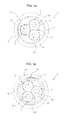
- the figure 1-b represents an alternative embodiment of the cable according to the invention.
- the conductors 20, 30, 40 are maintained in a rigorous geometric position thanks to a sheath 802 of polymer material, and possibly, additionally, a ribbon 60, for example polyester; the other technical characteristics of the cable remaining similar.
- the electrically insulating sheath 21, 31, 41 may be made of polyethylene (high density or low density), polypropylene, and more especially for applications requiring compliance with fire standards, polyethylene or filled polypropylene. (more generally called “zero halogen”); or alternatively polysiloxane, or polyethylene terephthalate; or all the polymeric materials mentioned above, crosslinked to have a better thermal and mechanical resistance.
- the attenuation level is indeed very low, whatever the frequency (eg less than or of the order of 10 dB over a distance of 100m up to 70 MHz, and less than 20 dB on a distance of 100m at a frequency of 100MHz).
- curve 2 of the figure 2 which compares a cable of the prior art, where the attenuation is already of the order of 20 dB over 100m for a frequency of 20MHz, and reaches about 50 dB over a distance of 100m at a frequency of 100MHz.
- the Applicant has tested many cables, and was able to note that the cables having a controlled geometric arrangement, rigorous or electrically conductive son and the possible screens or screens, combined with the fact that the or each insulating sheath 21, 31, 41 of the wire conductor has a dielectric loss angle ⁇ adapted, improved transmissions of PLC signals.
- the insulating materials are characterized in particular by the dielectric dissipation factor (often noted tg ( ⁇ ) - tangent of the angle ⁇ ) which characterizes the electrical charge losses because the material is not a perfect dielectric.
- the cables developed in the context of the invention are characterized by a dielectric dissipation factor tg ( ⁇ ) less than or equal to 5.10 -2 over a frequency range f between 1 MHz and 100 MHz.
- the cable according to the invention also has other relatively interesting features.
- the characteristic impedance Z C also depends on the permittivity dielectric insulation 21, 31, 41 surrounding each lead wire 20, 30, 40.
- the conductive wires (whether they are arranged in a trough or assembled in a geometrically rigorous manner, for example by a tight fitting) are surrounded by an insulating sheath made of polyvinyl chloride (PVC), chosen for its ability to meet electrical safety standards.
- PVC polyvinyl chloride
- PVC has a dielectric permittivity which varies very significantly as a function of frequency, which is detrimental to the transmission of data, the characteristic impedance Z c then being continuously variable with the frequency.
- the materials used for the insulating sheath 21, 31, 41 or the conductive son of the
- the electricity of the cable according to the invention also has a quasi-constant electrical permittivity over a wide range of frequencies, ranging from 1 MHz to 100 MHz.
- the Applicant has found that it was necessary to understand by quasi-constant that the permittivity varies at most by ⁇ 10%, preferably ⁇ 5%, around its nominal value. measured at 1 MHz and this over the entire frequency band that is sought to be used for PLC applications (namely from 1MHz to 100MHz).
- An improvement in the quality of the communication makes it possible to lower the constraints imposed on the CPL couplers arranged at the ends of the cable and thus make the PLC data transmission system more efficient while simplifying and reducing the costs of the couplers.
- the insulating sheath 21, 31, 41 will also be made of a material having a dielectric permittivity less than or equal to 3 over the frequency range from 1 MHz to 100 MHz, which is particularly the case with the materials presented in a non-limiting manner for the sheath (filled or unloaded polyethylene, filled polypropylene or not, polysiloxane, polyethylene terephthalate).
- one or more electromagnetic screens may be provided, for example disposed on the inner periphery of the cavity formed by the outer sheath of said cable.
- the screen 50 or if there are several, at least one of the electromagnetic screens (s) is for example made by a complex ribbon combining an aluminum layer and a polyester layer.
- the maximum permissible throughput of the network ie the maximum power that can be injected into the network
- pollution (radiation) issues of the network. environment ie the higher the injected power, the more the cable radiates.
- the cabling system radiates, especially because of the use of one or more screen (s) 50 in the cable according to the invention, the higher the power potentially injectable by the transmitters, the higher the transmittable rate is high, and better is the data communication.
- the invention also has the advantage of meeting the standards in force, particularly with regard to Decree 2006-1278 of 18 October 2006 (France) on electromagnetic compatibility, which states the responsibility of the installer on damage related to electromagnetic fields.
- the screened cable of the invention also has the advantage of improving the compatibility between the LC and VDSL2 technologies, technologies which, using the same frequency spectrum and the same process of data multiplexing are prone to cross-disturbance when they use supports placed in parallel.
- the presence of one or more screens 50 contributes to improving other characteristics such as fire resistance and the non-release of halogenated substances from the wires or cables in case of fire.
- a layer 70 of continuity in an electrically conductive material, for example made of tinned copper, in electrical contact with the metal face of the complex ribbon and allowing a connection of this screen to the ground at both ends of the cable.
Landscapes
- Insulated Conductors (AREA)
- Communication Cables (AREA)
Abstract
Description
L'invention est relative à un câble ou fil, destiné à transporter simultanément un courant électrique, permettant d'alimenter des appareils consommant plusieurs centaines de Watts, et des données à un débit pouvant dépasser 1Mbits/s.
L'invention peut en particulier trouver application pour les réseaux d'énergie domestiques ou les réseaux d'énergie tertiaires et industriels d'un ensemble immobilier.The invention relates to a cable or wire, intended to simultaneously carry an electric current, for powering devices consuming several hundred Watts, and data at a rate of more than 1Mbits / s.
The invention may in particular find application for home energy networks or tertiary and industrial energy networks of a housing complex.
Les réseaux électriques actuels sont soit constitués de fils électriques individuels isolés qui sont tirés dans des gaines ou goulottes et posés de façon non organisée dans cette gaine ou goulotte, soit de câbles électriques constitués de fils individuels assemblés ensemble et gainés.Current electrical networks are either individual insulated electrical son that are pulled into ducts or chutes and posed in an unorganized way in this sheath or chute, or electrical cables consisting of individual son assembled together and sheathed.
Ces fils ou câbles d'énergie (électriques) répondent à un ensemble de normes relatives à:
- leurs capacités à transmettre l'énergie électrique ;
- leurs propriétés de protection électrique des biens et des personnes ;
- leur comportement à la flamme et à l'incendie.
- their ability to transmit electrical energy;
- their electrical protection properties of goods and persons;
- their behavior in the flame and fire.
Depuis plusieurs années, on cherche des solutions pour que des fils ou câbles d'énergie puissent également transmettre des informations.For several years, we have been looking for solutions so that energy wires or cables can also transmit information.
On trouve ainsi comme application :
- la transmission d'informations à bas ou moyens débits sur ces fils ou câbles d'énergie permettant d'assurer un pilotage d'appareils dans l'habitat, comme, par exemple, la télécommande d'appareils domestiques par réseau d'énergie ; ou encore
- la transmission de données informatiques pour relier des ordinateurs entres eux ou assurer la transmission de services aussi divers que les sons ou les images.
- the transmission of information at low or medium rates on these energy wires or cables making it possible to control appliances in the home, such as, for example, the remote control of household appliances by energy network; or
- the transmission of computer data to connect computers between them or to provide the transmission of services as diverse as sounds or images.
Pour cela, il a été mis en place la technique dite de « Courant Porteur en Ligne » (CPL).For this, it has been implemented the technique called "Current Carrier Online" (CPL).
La technique CPL est basée sur le multiplexage en fréquence de porteuses transportant les données. Ces porteuses sont typiquement étalées sur un spectre de fréquence allant de 2 à 30 MHz assurant des transmissions de données à un débit de l'ordre de 200 Mbits/s. Il est par ailleurs prévu que les produits en cours de développement puissent atteindre un débit de transmission de données de l'ordre de 1 Gbits/s, en s'appuyant sur des méthodes d'encodage optimisées, et en utilisant un spectre de fréquences porteuses allant de 2 à 100MHz.The CPL technique is based on the frequency multiplexing of carriers carrying the data. These carriers are typically spread over a frequency spectrum from 2 to 30 MHz ensuring data transmissions at a rate of the order of 200 Mbps. It is also expected that products under development can reach a data transmission rate of the order of 1 Gbit / s, based on optimized encoding methods, and using a carrier frequency spectrum ranging from 2 to 100MHz.
On utilise donc actuellement des solutions basées sur des techniques de multiplexage de l'information véhiculée dans des câbles ou fils dont la structure a été uniquement adaptée et pensée pour le transport de l'énergie électrique.Solutions are therefore currently used based on information multiplexing techniques conveyed in cables or wires whose structure has been adapted only and designed for the transport of electrical energy.
En effet, dans le cas de fils d'énergie, du fait d'un positionnement anarchique des fils dans la goulotte, l'impédance caractéristique est extrêmement variable et non prédictible. De plus, l'atténuation de ces fils sur la puissance de transmission des informations a tendance à fortement augmenter au delà d'une fréquence de 40 MHz (Ce comportement est illustré par la courbe 3 de la
Dans le cas des câbles d'énergie, du fait d'un positionnement plus rigoureux des fils conducteurs, l'impédance caractéristique est prédictible et relativement lisse, mais l'atténuation linéique de ces câbles est très élevée (voir courbe 2 de la
Un exemple d'un tel câble d'énergie est illustré dans le brevet
Par ailleurs, ces fils ou câbles d'énergie ne sont pas prévus pour se protéger des perturbations électromagnétiques environnantes ce qui a une influence néfaste sur le rapport signal sur bruit et donc sur la qualité de la transmission de données. Qui plus est, ces fils ou câbles d'énergie ne sont pas conçus pour protéger l'environnement des perturbations électromagnétiques qu'ils génèrent, et ces perturbations augmentent dès qu'ils sont utilisés comme support de transmission de données.Moreover, these energy wires or cables are not designed to protect themselves from surrounding electromagnetic disturbances which has a detrimental influence on the signal-to-noise ratio and therefore on the quality of the data transmission. Moreover, these energy wires or cables are not designed to protect the environment from the electromagnetic disturbances they generate, and these disturbances increase as soon as they are used as a data transmission medium.
Il n'existe donc pas aujourd'hui de fils ou câbles d'énergie conçus pour tirer le meilleur parti possible des solutions CPL actuelles ou à venir en termes de débit de transmission, d'atténuation du signal, et également en termes de protection électromagnétique par rapport à l'environnement.Therefore, there are no energy wires or cables designed to make the most of current or future PLC solutions in terms of transmission rate, signal attenuation, and also electromagnetic protection. compared to the environment.
Un objectif de l'invention est donc de proposer un fil ou câble de transport d'énergie, dont les caractéristiques de transmission de données sont améliorées.An object of the invention is therefore to provide a power transmission wire or cable, whose data transmission characteristics are improved.
Un objectif de l'invention est de proposer un fil ou câble de transport d'énergie, offrant à la fois une impédance caractéristique relativement constante sur une large gamme de fréquences et une atténuation de la puissance du signal d'information relativement faible, sur cette même gamme de fréquences.An object of the invention is to provide a power transmission wire or cable, offering both a relatively constant characteristic impedance over a wide frequency range and a relatively low power attenuation of the information signal, on this same frequency range.
Un autre objectif de l'invention est de proposer un fil ou câble de transport d'énergie, présentant les caractéristiques techniques mentionnées ci-dessus, ainsi qu'une amélioration de la protection électromagnétique par rapport à l'environnement, à savoir une diminution de la sensibilité aux perturbations électromagnétiques environnantes, et une diminution des perturbations électromagnétiques générées sur l'environnement.Another object of the invention is to propose a power transmission wire or cable, having the technical characteristics mentioned above, as well as an improvement of the electromagnetic protection with respect to the environment, namely a reduction of sensitivity to surrounding electromagnetic disturbances, and a decrease in electromagnetic disturbances generated on the environment.
L'un au moins de ces objectifs est atteint au moyen d'un câble comportant une gaine extérieure définissant une cavité dans laquelle sont disposés un ou plusieurs fils conducteurs de l'électricité, le ou chaque fil conducteur étant entouré d'une gaine isolante électriquement, ledit câble étant par ailleurs destiné à transporter simultanément un courant électrique permettant d'alimenter des appareils consommant plusieurs centaines de Watts et des données à un débit pouvant dépasser 1Mbits/s, caractérisé en ce que, le ou chaque fil conducteur, maintenu dans une position géométrique rigoureuse au sein de la gaine extérieure, comporte une gaine isolante électriquement en un matériau présentant un facteur de dissipation diélectrique inférieur ou égal à 5.10-2 sur une gamme de fréquences f comprise entre 1MHz et 100MHz.At least one of these objectives is achieved by means of a cable comprising an outer sheath defining a cavity in which one or more electrically conductive wires are arranged, the or each conductive wire being surrounded by an electrically insulating sheath. , said cable being further intended to simultaneously convey an electric current for powering devices consuming several hundred Watts and data at a rate of more than 1Mbits / s, characterized in that the or each conductive wire, maintained in a rigorous geometric position within the outer sheath, comprises an electrically insulating sheath of a material having a dielectric dissipation factor of less than or equal to 5.10 -2 over a frequency range f between 1 MHz and 100 MHz.
Le câble selon l'invention pourra également comprendre au moins l'une des caractéristiques techniques suivantes, prise en elle-même, ou en combinaison :
- la gaine isolante est faite en un matériau présentant une permittivité diélectrique εr quasi-constante sur la gamme de fréquences allant de 1MHz à 100MHz, c'est-à-dire présentant une variation maximum de 10%, et préférentiellement de 5%, de sa valeur nominale mesurée à 1MHz ;
- la gaine isolante est faite en un matériau présentant une permittivité diélectrique inférieure à 3,2 sur la gamme de fréquences allant de 1MHz à 100MHz ;
- la gaine isolante électriquement est faite en polyéthylène chargé ou non, ou encore en polypropylène chargé ou non, le polyéthylène ou le polypropylène pouvant être réticulé ou non ;
- la gaine isolante électriquement est faite en polysiloxane réticulé ou non ou en polyéthylène téréphtalate réticulé ou non ;
- les fils conducteurs sont maintenus avec un ruban entourant lesdits fils conducteurs, par exemple en polyester ;
- le ou les fils conducteurs sont maintenus en position rigoureuse les uns par rapport aux autres à l'aide d'un matériau de bourrage ;
- le ou les fils conducteurs sont maintenus en position rigoureuse les uns par rapport aux autres à l'aide d'une gaine en matériau polymère ;
- les fils conducteurs sont torsadés ensemble ;
- le pas de torsadage est compris entre 100mm et 300mm, de préférence de l'ordre de 200mm ;
- il est prévu un ou plusieurs écran(s) électromagnétique(s), le ou chaque écran est disposé de manière géométriquement rigoureuse au sein du câble, à savoir à distance constante des autres éléments électriques constituant le câble ;
- le ou l'un au moins des écran(s) électromagnétique(s) comprend un ruban constitué d'au moins une couche d'aluminium et d'une couche de polyester ;
- le ou l'un au moins des écrans est disposé sur la périphérie intérieure de la cavité formée par la gaine extérieure dudit câble ;
- le câble prévoit, entre la périphérie intérieure de la cavité formée par la gaine extérieure dudit câble et le ou l'un des écran(s), une nappe de continuité en un matériau conducteur de l'électricité, par exemple en cuivre étamé, en contact électrique avec une face métallique de l'écran et permettant un raccordement à la terre aux extrémités du câble installé.
- the insulating sheath is made of a material having a quasi-constant dielectric permittivity ε r over the frequency range from 1 MHz to 100 MHz, that is to say having a maximum variation of 10%, and preferably 5%, of its nominal value measured at 1 MHz;
- the insulating sheath is made of a material having a dielectric permittivity of less than 3.2 over the frequency range from 1MHz to 100MHz;
- the electrically insulating sheath is made of filled polyethylene or not, or polypropylene loaded or not, the polyethylene or polypropylene may be crosslinked or not;
- the electrically insulating sheath is made of cross-linked or non-crosslinked polysiloxane or crosslinked polyethylene terephthalate or not;
- the conductive son are held with a ribbon surrounding said conductive son, for example polyester;
- the one or more conducting wires are held in a rigorous position relative to one another by means of a stuffing material;
- the conductor son or son are maintained in a rigorous position relative to each other by means of a sheath made of polymeric material;
- the conductive wires are twisted together;
- the pitch of twisting is between 100mm and 300mm, preferably of the order of 200mm;
- one or more electromagnetic screen (s) is provided, the or each screen is arranged in a geometrically rigorous manner within the cable, namely at a constant distance from the other electrical elements constituting the cable;
- the at least one electromagnetic screen (s) comprises a ribbon consisting of at least one layer of aluminum and a layer of polyester;
- the at least one screen is disposed on the inner periphery of the cavity formed by the outer sheath of said cable;
- the cable provides, between the inner periphery of the cavity formed by the outer sheath of said cable and the or one of the screen (s), a continuity ply made of an electrically conductive material, for example tinned copper, in electrical contact with a metal face of the screen and allowing a ground connection to the ends of the installed cable.
D'autres caractéristiques, buts et avantages de la présente invention apparaîtront à la lecture de la description détaillée qui va suivre.Other features, objects and advantages of the present invention will appear on reading the detailed description which follows.
-
la
figure 1-a représente un schéma de coupe d'un câble selon l'invention ;thefigure 1-a represents a sectional diagram of a cable according to the invention; -
la
figure 1-b représente un schéma de coupe d'un autre mode de réalisation d'un câble selon l'inventionthefigure 1-b represents a sectional diagram of another embodiment of a cable according to the invention -
la
figure 2 représente des résultats de tests fournissant l'atténuation d'un signal transmettant des données sur plusieurs types de câble d'énergie pour le transport d'électricité, en fonction de la fréquence dudit signal.thefigure 2 represents test results providing the attenuation of a signal transmitting data on several types of power cable for the transmission of electricity, as a function of the frequency of said signal.
La
Le câble 1 comporte une gaine extérieure 10 définissant une cavité dans laquelle sont disposés un ou plusieurs fils conducteurs.The
Dans l'exemple illustré sur la
Sur la
A titre d'exemple non limitatif, il faut entendre par là que le ou chaque fil conducteur, ainsi que le ou chaque écran est disposé à distance constante des autres éléments électriques constituant le câble.By way of non-limiting example, it should be understood that the or each conductive wire, and the or each screen is disposed at a constant distance from the other electrical elements constituting the cable.
Plus particulièrement, lorsque plusieurs fils conducteurs sont prévus, il faut aussi entendre par là que ceux-ci peuvent être disposés parallèlement (à distance constante l'un de l'autre) les uns par rapport aux autres sur toute leur longueur.More particularly, when several son drivers are provided, it should also be understood that they can be arranged parallel (at a constant distance from one another) relative to each other over their entire length.
De façon alternative, on pourra prévoir que les (au nombre de trois dans l'exemple illustré sur la
Pour maintenir plusieurs fils conducteurs 20, 30, 40 en position géométrique rigoureuse l'un par rapport à l'autre (qu'ils soient parallèles ou torsadés entre eux), on pourra prévoir un ruban 60 les enveloppant, par exemple constitué de polyester. On peut également, de manière additionnelle ou alternative, employer un matériau polymère 801 déposé par extrusion (technique dite du bourrage consistant à boucher les trous pour rendre la section du câble cylindrique) pour maintenir les fils à l'intérieur du câble dans une position géométrique prédéterminée.To maintain
Dans le cas où les fils conducteurs 20, 30, 40 sont torsadés entre eux, le pas de torsadage pourra être compris entre 100mm et 300mm, de préférence de l'ordre de 200mm. Un tel pas, en particulier lorsqu'il est de l'ordre de 200mm, permet de donner au câble une certaine flexibilité, améliorant ainsi sa mise en oeuvre et facilitant son lovage sur touret.In the case where the
La
Dans cet exemple, au sein du câble 2, les conducteurs 20, 30, 40 sont maintenus dans une position géométrique rigoureuse grâce à une gaine 802 en matériau polymère, et éventuellement, de façon additionnelle, par un ruban 60, par exemple en polyester; les autres caractéristiques techniques du câble restant similaires.In this example, in the
Dans le cas des
A titre d'exemples non limitatifs, la gaine isolante électriquement 21, 31, 41 peut être en polyéthylène (haute densité ou basse densité), polypropylène, et plus spécialement pour les applications nécessitant le respect de normes incendie, du polyéthylène ou du polypropylène chargé (plus généralement appelés « zéro halogène ») ; ou encore le polysiloxane, ou le polyéthylène téréphtalate; ou encore tous les matériaux polymères cités précédemment, réticulés pour présenter une meilleure résistance thermique et mécanique.By way of nonlimiting examples, the electrically insulating
Or, il a été constaté qu'un tel câble permettait d'obtenir des niveaux d'atténuation extrêmement faibles, et quasiment constants sur une très large gamme de fréquences, typiquement entre 1MHz et 100MHz.However, it has been found that such a cable makes it possible to obtain extremely low attenuation levels, and almost constant over a very wide frequency range, typically between 1 MHz and 100 MHz.
Un tel effet peut notamment être visualisé sur la courbe 4 de la
Sur cette courbe 4, le niveau d'atténuation est effectivement très faible, quelle que soit la fréquence (ex : inférieure ou de l'ordre de 10 dB sur une distance de 100m jusqu'à 70 MHz, et inférieure à 20 dB sur une distance de 100m à une fréquence de 100MHz).On this
Ceci est tout à fait surprenant dans la mesure où les câbles d'énergie actuels présentant un arrangement géométrique rigoureux des fils conducteurs sont connus (comme rappelé dans la partie « art antérieur » de la présente demande) comme des câbles présentant une atténuation très élevée, qui ne fait par ailleurs qu'augmenter avec l'augmentation de la fréquence du signal transmis.This is quite surprising insofar as the current energy cables having a rigorous geometrical arrangement of the conducting wires are known (as recalled in the "prior art" part of the present application) as cables having a very high attenuation, which, moreover, only increases with the increase of the frequency of the transmitted signal.
On peut notamment se reporter à la courbe 2 de la
Afin de mieux caractériser les câbles susceptibles de répondre aux exigences d'amélioration des câbles existants, la Demanderesse a testé de nombreux câbles, et a pu constater que les câbles présentant un arrangement géométrique maîtrisé, rigoureux du ou des fils conducteurs de l'électricité et du ou des écrans éventuels, combiné au fait que la ou chaque gaine isolante 21, 31, 41 du fil conducteur présente un angle de perte diélectrique δ adapté, amélioraient les transmissions des signaux CPL.In order to better characterize the cables likely to meet the requirements for improving existing cables, the Applicant has tested many cables, and was able to note that the cables having a controlled geometric arrangement, rigorous or electrically conductive son and the possible screens or screens, combined with the fact that the or each insulating
Plus précisément, les matières isolantes sont notamment caractérisées par le facteur de dissipation diélectrique (souvent noté tg(δ) - tangente de l'angle δ) qui caractérise les pertes de charges électriques du fait que le matériau n'est pas un diélectrique parfait.More specifically, the insulating materials are characterized in particular by the dielectric dissipation factor (often noted tg (δ) - tangent of the angle δ) which characterizes the electrical charge losses because the material is not a perfect dielectric.
On a ainsi pu montrer que les câbles développés dans le cadre de l'invention se caractérisent par un facteur de dissipation diélectrique tg(δ) inférieur ou égal à 5.10-2 sur une gamme de fréquences f comprise entre 1MHz et 100MHz.It has thus been possible to show that the cables developed in the context of the invention are characterized by a dielectric dissipation factor tg (δ) less than or equal to 5.10 -2 over a frequency range f between 1 MHz and 100 MHz.
Le câble selon l'invention présente également d'autres caractéristiques relativement intéressantes.The cable according to the invention also has other relatively interesting features.
Il est en effet connu que l'impédance caractéristique Zc du câble peut s'écrire sous la forme : 
Où
- K est une constante ;
- Vr est la vitesse relative du signal transmis dans le fil conducteur par rapport à la célérité de la lumière dans le vide ;
- d est le diamètre du fil conducteur ;
- D est la distance séparant le centre de ces fils conducteurs ;
- ε r est la permittivité diélectrique de la gaine isolante entourant le fil conducteur.
- K is a constant;
- V r is the relative speed of the signal transmitted in the conductor wire with respect to the speed of light in the vacuum;
- d is the diameter of the conductive wire;
- D is the distance separating the center of these conductive wires;
- ε r is the dielectric permittivity of the insulating sheath surrounding the conductor wire.
On comprend plus précisément par cette relation (1) qu'une construction géométriquement rigoureuse des fils assemblés dans le câble stabilise l'impédance caractéristique (la distance D est maîtrisée et relativement constante).It is more precisely understood by this relation (1) that a geometrically rigorous construction of the wires assembled in the cable stabilizes the characteristic impedance (the distance D is controlled and relatively constant).
Là est donc la différence entre par exemple un câble avec trois fils conducteurs en cuivre de 2.5mm2 tirés en goulotte (D varie le long de la goulotte), et un câble avec trois fils conducteurs en cuivre de 2.5mm2 assemblés rigoureusement (D constant).So there is the difference between for example a cable with three copper conductors of 2.5mm 2 pulled in chute (D varies along the chute), and a cable with three 2.5mm copper conductor wires 2 rigorously assembled (D constant).
Toutefois, comme on peut le voir par l'intermédiaire de la relation (1), l'impédance caractéristique ZC dépend également de la permittivité diélectrique de l'isolant 21, 31, 41 entourant chaque fil conducteur 20, 30, 40.However, as can be seen through relation (1), the characteristic impedance Z C also depends on the
Classiquement, les fils conducteurs (qu'ils soient disposés en goulotte ou assemblés de manière rigoureuse sur le plan géométrique, par un montage serré par exemple) sont entourés d'une gaine isolante en polychlorure de vinyle (PVC), choisi pour sa capacité à répondre aux normes de sécurité électrique.Conventionally, the conductive wires (whether they are arranged in a trough or assembled in a geometrically rigorous manner, for example by a tight fitting) are surrounded by an insulating sheath made of polyvinyl chloride (PVC), chosen for its ability to meet electrical safety standards.
Or, on a remarqué que le PVC présente une permittivité diélectrique qui varie de façon très sensible en fonction de la fréquence, ce qui s'avère préjudiciable pour la transmission de données, l'impédance caractéristique Zc étant alors continument variable avec la fréquence.However, it has been noted that PVC has a dielectric permittivity which varies very significantly as a function of frequency, which is detrimental to the transmission of data, the characteristic impedance Z c then being continuously variable with the frequency.
Or, les matériaux (à titre non limitatif polyéthylène chargé ou non, polypropylène chargé ou non, polysiloxane, polyéthylène téréphtalate, ces polymères étant réticulés ou non) mis en oeuvre pour la gaine isolante 21, 31, 41 du ou des fils conducteurs de l'électricité du câble selon l'invention présentent également une permittivité électrique quasi-constante sur une large gamme de fréquences, pouvant aller de 1MHz à 100MHz.However, the materials (non-limiting polyethylene loaded or not, polypropylene loaded or not, polysiloxane, polyethylene terephthalate, these polymers being crosslinked or not) used for the insulating
Là encore, pour mieux caractériser les câbles présentant cette caractéristique, la Demanderesse a constaté qu'il fallait comprendre par quasi-constante le fait que la permittivité varie au maximum de ±10%, de préférence de ±5%, autour de sa valeur nominale mesurée à 1 MHz et ceci sur l'ensemble de la bande de fréquences que l'on cherche à utiliser pour les applications CPL (à savoir de 1MHz à 100MHz).Again, to better characterize the cables having this characteristic, the Applicant has found that it was necessary to understand by quasi-constant that the permittivity varies at most by ± 10%, preferably ± 5%, around its nominal value. measured at 1 MHz and this over the entire frequency band that is sought to be used for PLC applications (namely from 1MHz to 100MHz).
Ainsi, le fait d'avoir un câble avec une construction géométrique rigoureuse des fils conducteurs d'une part et une gaine isolante du ou de ces fils conducteurs en un matériau spécifique d'autre part permet d'améliorer encore la stabilisation de l'impédance caractéristique par rapport aux câbles existants, et permet de mieux contrôler la qualité de la transmission des données dans un câblage utilisant les câbles selon l'invention.Thus, having a cable with a rigorous geometric construction of the conductive wires on the one hand and an insulating sheath of the conductive wire or wires in a specific material on the other hand makes it possible to further improve the stabilization of the impedance feature over existing cables, and allows better control of the quality of data transmission in a cabling using the cables according to the invention.
Une amélioration de la qualité de la communication permet d'abaisser les contraintes imposées aux coupleurs CPL disposés aux extrémités du câble et donc de rendre plus efficace le système de transmission de données CPL tout en simplifiant et diminuant les coûts des coupleurs.An improvement in the quality of the communication makes it possible to lower the constraints imposed on the CPL couplers arranged at the ends of the cable and thus make the PLC data transmission system more efficient while simplifying and reducing the costs of the couplers.
De préférence, mais non limitativement, la gaine isolante 21, 31, 41 sera également faite en un matériau présentant une permittivité diélectrique inférieure ou égale à 3 sur la gamme de fréquences allant de 1MHz à 100MHz, ce qui est en particulier le cas des matériaux présentés à titre non limitatifs pour la gaine (polyéthylène chargé ou non, polypropylène chargé ou non, polysiloxane, polyéthylène téréphtalate).Preferably, but not exclusively, the insulating
Ceci permet avantageusement de prévenir toute influence de la permittivité diélectrique sur le niveau d'atténuation pour les fréquences faibles, à savoir de l'ordre du MHz ou inférieures à quelques MHz.This advantageously makes it possible to prevent any influence of the dielectric permittivity on the attenuation level for the low frequencies, namely of the order of 1 MHz or less than a few MHz.
Pour diminuer la sensibilité aux perturbations électromagnétiques extérieures, mais aussi pour diminuer le rayonnement électromagnétique généré par le câble sur son environnement, on pourra prévoir un ou plusieurs écrans 50 électromagnétique(s), par exemple disposé sur la périphérie intérieure de la cavité formée par la gaine extérieure dudit câble.To reduce the sensitivity to external electromagnetic disturbances, but also to reduce the electromagnetic radiation generated by the cable on its environment, one or more electromagnetic screens may be provided, for example disposed on the inner periphery of the cavity formed by the outer sheath of said cable.
L'écran 50, ou s'il en est prévu plusieurs, l'un au moins des écrans électromagnétique(s) est par exemple réalisé par un ruban complexe associant une couche d'aluminium et une couche de polyester.The
Dans le cas des transmissions de données, notamment par CPL, le débit maximum admissible par le réseau (c'est-à-dire la puissance maximale pouvant être injectée dans le réseau) est limité pour des questions de pollution (rayonnement) de l'environnement. En effet, plus la puissance injectée est importante, plus le câble rayonne.In the case of data transmissions, in particular by PLC, the maximum permissible throughput of the network (ie the maximum power that can be injected into the network) is limited for pollution (radiation) issues of the network. environment. Indeed, the higher the injected power, the more the cable radiates.
Ainsi, moins le système de câblage rayonne, notamment en raison de l'emploi d'un ou plusieurs écran(s) 50 dans le câble selon l'invention, plus la puissance potentiellement injectable par les émetteurs est forte, plus le débit transmissible est élevé, et meilleure est la communication de données.Thus, the less the cabling system radiates, especially because of the use of one or more screen (s) 50 in the cable according to the invention, the higher the power potentially injectable by the transmitters, the higher the transmittable rate is high, and better is the data communication.
Par ce biais, l'invention présente également l'avantage de répondre aux normes en vigueur, en particulier en ce qui concerne le décret 2006-1278 du 18 octobre 2006 (France) sur la compatibilité électromagnétique, qui stipule la responsabilité de l'installateur sur des dommages liés aux champs électromagnétiques.In this way, the invention also has the advantage of meeting the standards in force, particularly with regard to Decree 2006-1278 of 18 October 2006 (France) on electromagnetic compatibility, which states the responsibility of the installer on damage related to electromagnetic fields.
La présence d'un ou de plusieurs écrans permet également la réalisation simple de liaisons équipotentielles fonctionnelles (utilisée pour améliorer la transmission de données et diminuer les pollutions CEM). Ces réalisations sont associées aux systèmes de câblage d'énergie en accord avec les préconisations des normalisations NFC 15 100 chapitre 545 "dispositions de mise à la terre et liaisons équipotentielles fonctionnelles" et du guide UTE C 15 900 chapitre 6.9.The presence of one or more screens also allows the simple realization of functional equipotential bonds (used to improve data transmission and reduce EMC pollution). These embodiments are associated with energy cabling systems in accordance with the recommendations of standardizations NFC 15 100 chapter 545 "provisions for earthing and functional equipotential bonding" and of the guide UTE C 15 900 chapter 6.9.
Le câble écranté de l'invention présente également l'avantage d'améliorer la compatibilité entre les technologies CPL et VDSL2, technologies qui, utilisant le même spectre de fréquence et le même processus de multiplexage des données sont sujettes à des perturbations croisées quand ils utilisent des supports posés en parallèle.The screened cable of the invention also has the advantage of improving the compatibility between the LC and VDSL2 technologies, technologies which, using the same frequency spectrum and the same process of data multiplexing are prone to cross-disturbance when they use supports placed in parallel.
Par ailleurs, la présence d'un ou plusieurs écran(s) 50 participe à améliorer d'autres caractéristiques comme notamment la tenue au feu et le non dégagement de substances halogénées des fils ou câbles en cas d'incendie.Moreover, the presence of one or
Enfin, on pourra également prévoir, entre la périphérie intérieure de la cavité formée par la gaine extérieure dudit câble et le ou l'un des écran(s), une nappe 70 de continuité en un matériau conducteur de l'électricité, par exemple en cuivre étamé, en contact électrique avec la face métallique du ruban complexe et permettant un raccordement de cet écran à la terre aux deux extrémités du câble.Finally, it is also possible to provide, between the inner periphery of the cavity formed by the outer sheath of said cable and the one or one of the screen (s), a
Claims (15)
Applications Claiming Priority (1)
| Application Number | Priority Date | Filing Date | Title |
|---|---|---|---|
| FR0855088A FR2934411B1 (en) | 2008-07-24 | 2008-07-24 | ENERGY CABLE SPECIFICALLY DESIGNED TO TRANSMIT HIGH SPEED DATA. |
Publications (2)
| Publication Number | Publication Date |
|---|---|
| EP2148336A1 true EP2148336A1 (en) | 2010-01-27 |
| EP2148336B1 EP2148336B1 (en) | 2012-06-06 |
Family
ID=40345055
Family Applications (1)
| Application Number | Title | Priority Date | Filing Date |
|---|---|---|---|
| EP20090166133 Active EP2148336B1 (en) | 2008-07-24 | 2009-07-22 | Power cable specifically designed for high-speed data transmission |
Country Status (2)
| Country | Link |
|---|---|
| EP (1) | EP2148336B1 (en) |
| FR (1) | FR2934411B1 (en) |
Cited By (1)
| Publication number | Priority date | Publication date | Assignee | Title |
|---|---|---|---|---|
| CN105702372A (en) * | 2015-01-20 | 2016-06-22 | 王笑梅 | Cable for high-voltage connection |
Families Citing this family (1)
| Publication number | Priority date | Publication date | Assignee | Title |
|---|---|---|---|---|
| DE102021116629A1 (en) | 2021-06-28 | 2022-12-29 | Lapp Engineering Ag | Cable |
Citations (6)
| Publication number | Priority date | Publication date | Assignee | Title |
|---|---|---|---|---|
| US4156869A (en) * | 1977-06-20 | 1979-05-29 | The United States Of America As Represented By The Secretary Of The Navy | Conducting cable |
| US4997992A (en) * | 1989-06-26 | 1991-03-05 | Low William E | Low distortion cable |
| GB2264424A (en) * | 1992-02-12 | 1993-08-25 | Alcatel Kabel Norge As | Improvements in or relating to signal transmission |
| US5763823A (en) * | 1996-01-12 | 1998-06-09 | Belden Wire & Cable Company | Patch cable for high-speed LAN applications |
| FR2838002A1 (en) * | 2002-03-27 | 2003-10-03 | Electricite De France | Power line communication system has capacitive coupling of three phase line cable pairs to excite differential bipolar mode. |
| FR2848718A1 (en) | 2002-12-11 | 2004-06-18 | France Telecom | Electrical network e.g. computer broadband network, cable for private installation, has three wires for phase, neutral and ground respectively, and are bunched together to form bunched conductor to transmit low tension current |
-
2008
- 2008-07-24 FR FR0855088A patent/FR2934411B1/en not_active Expired - Fee Related
-
2009
- 2009-07-22 EP EP20090166133 patent/EP2148336B1/en active Active
Patent Citations (6)
| Publication number | Priority date | Publication date | Assignee | Title |
|---|---|---|---|---|
| US4156869A (en) * | 1977-06-20 | 1979-05-29 | The United States Of America As Represented By The Secretary Of The Navy | Conducting cable |
| US4997992A (en) * | 1989-06-26 | 1991-03-05 | Low William E | Low distortion cable |
| GB2264424A (en) * | 1992-02-12 | 1993-08-25 | Alcatel Kabel Norge As | Improvements in or relating to signal transmission |
| US5763823A (en) * | 1996-01-12 | 1998-06-09 | Belden Wire & Cable Company | Patch cable for high-speed LAN applications |
| FR2838002A1 (en) * | 2002-03-27 | 2003-10-03 | Electricite De France | Power line communication system has capacitive coupling of three phase line cable pairs to excite differential bipolar mode. |
| FR2848718A1 (en) | 2002-12-11 | 2004-06-18 | France Telecom | Electrical network e.g. computer broadband network, cable for private installation, has three wires for phase, neutral and ground respectively, and are bunched together to form bunched conductor to transmit low tension current |
Cited By (1)
| Publication number | Priority date | Publication date | Assignee | Title |
|---|---|---|---|---|
| CN105702372A (en) * | 2015-01-20 | 2016-06-22 | 王笑梅 | Cable for high-voltage connection |
Also Published As
| Publication number | Publication date |
|---|---|
| FR2934411B1 (en) | 2011-04-01 |
| FR2934411A1 (en) | 2010-01-29 |
| EP2148336B1 (en) | 2012-06-06 |
Similar Documents
| Publication | Publication Date | Title |
|---|---|---|
| FR2730341A1 (en) | IMPROVED CABLE WITH MULTIPLE DIFFERENTIAL PAIRS OF CONDUCTORS | |
| US6600108B1 (en) | Electric cable | |
| FR2693828A1 (en) | Signal cable with a metal-coated polymer screen. | |
| EP0068308A1 (en) | Electro-mechanical cable resistant to elevated temperature and pressure, and method for its manufacture | |
| EP2765581B1 (en) | Electric cable resistant to partial discharges | |
| FR2850788A1 (en) | Transmission cable for connecting mobile device e.g. crane, with voltage source, has electric screen formed around film to present metallic band formed in closed envelope of tubular form and to present good electric conduction | |
| EP0871182B1 (en) | High data rate flat signal transmission cable | |
| EP2148336B1 (en) | Power cable specifically designed for high-speed data transmission | |
| CN109448901A (en) | Loss coaxial cables | |
| US9117566B2 (en) | Impedance controlled subsea ethernet oil filled hose | |
| EP0141961A1 (en) | Radiating coaxial cable | |
| EP0624885B1 (en) | Cable usable within the telecommunications field | |
| FR3062748A1 (en) | ELECTRICAL CABLE RESISTANT TO PARTIAL DISCHARGES | |
| EP2760030A1 (en) | Power and/or telecommunications cable comprising at least one electrically insulating layer | |
| EP0577467B1 (en) | Mixed communication and power cable | |
| EP1163682B1 (en) | Radiating cable | |
| EP1016165A1 (en) | Radiating cable | |
| FR3011670A1 (en) | ELECTRIC HARNESS WITH LOW LINEAR CAPACITY | |
| FR3085224A1 (en) | WIRING SYSTEM | |
| FR3078435A1 (en) | CABLE FOR COMMUNICATION AND MULTIMEDIA TRANSMISSION | |
| US9355760B2 (en) | Integrating optical fiber with coaxial cable | |
| FR2920918A1 (en) | Radiating cable i.e. coaxial cable, for radio communication system in e.g. building, has sheath made of insulating material that is obtained by composition comprising polymer and iron oxide so that material has permittivity equal to six | |
| FR2690280A1 (en) | Coaxial cable antenna for tunnel telecommunications or confined spaces - has coaxial cable with outer slots and second single wire, both enclosed separately by outer figure-eight shaped sleeve | |
| FR2852746A1 (en) | High voltage electric power underground transmission system, has metallic shield integrated along internal cavity of installation pipe for grounding and being independent of electric power cable | |
| FR3019370A1 (en) | DEVICE FOR ELECTROMAGNETIC SHIELDING OF CABLES |
Legal Events
| Date | Code | Title | Description |
|---|---|---|---|
| PUAI | Public reference made under article 153(3) epc to a published international application that has entered the european phase |
Free format text: ORIGINAL CODE: 0009012 |
|
| AK | Designated contracting states |
Kind code of ref document: A1 Designated state(s): AT BE BG CH CY CZ DE DK EE ES FI FR GB GR HR HU IE IS IT LI LT LU LV MC MK MT NL NO PL PT RO SE SI SK SM TR |
|
| AX | Request for extension of the european patent |
Extension state: AL BA RS |
|
| 17P | Request for examination filed |
Effective date: 20100726 |
|
| GRAP | Despatch of communication of intention to grant a patent |
Free format text: ORIGINAL CODE: EPIDOSNIGR1 |
|
| GRAC | Information related to communication of intention to grant a patent modified |
Free format text: ORIGINAL CODE: EPIDOSCIGR1 |
|
| GRAS | Grant fee paid |
Free format text: ORIGINAL CODE: EPIDOSNIGR3 |
|
| GRAA | (expected) grant |
Free format text: ORIGINAL CODE: 0009210 |
|
| RAP1 | Party data changed (applicant data changed or rights of an application transferred) |
Owner name: ACOME SOCIETE COOPERATIVE ET PARTICIPATIVE SOCIETE |
|
| AK | Designated contracting states |
Kind code of ref document: B1 Designated state(s): AT BE BG CH CY CZ DE DK EE ES FI FR GB GR HR HU IE IS IT LI LT LU LV MC MK MT NL NO PL PT RO SE SI SK SM TR |
|
| REG | Reference to a national code |
Ref country code: GB Ref legal event code: FG4D Free format text: NOT ENGLISH |
|
| REG | Reference to a national code |
Ref country code: AT Ref legal event code: REF Ref document number: 561370 Country of ref document: AT Kind code of ref document: T Effective date: 20120615 Ref country code: CH Ref legal event code: EP |
|
| REG | Reference to a national code |
Ref country code: IE Ref legal event code: FG4D Free format text: LANGUAGE OF EP DOCUMENT: FRENCH |
|
| REG | Reference to a national code |
Ref country code: CH Ref legal event code: NV Representative=s name: MICHELI & CIE SA |
|
| REG | Reference to a national code |
Ref country code: DE Ref legal event code: R096 Ref document number: 602009007438 Country of ref document: DE Effective date: 20120802 |
|
| REG | Reference to a national code |
Ref country code: NL Ref legal event code: VDEP Effective date: 20120606 |
|
| PG25 | Lapsed in a contracting state [announced via postgrant information from national office to epo] |
Ref country code: LT Free format text: LAPSE BECAUSE OF FAILURE TO SUBMIT A TRANSLATION OF THE DESCRIPTION OR TO PAY THE FEE WITHIN THE PRESCRIBED TIME-LIMIT Effective date: 20120606 Ref country code: NO Free format text: LAPSE BECAUSE OF FAILURE TO SUBMIT A TRANSLATION OF THE DESCRIPTION OR TO PAY THE FEE WITHIN THE PRESCRIBED TIME-LIMIT Effective date: 20120906 Ref country code: SE Free format text: LAPSE BECAUSE OF FAILURE TO SUBMIT A TRANSLATION OF THE DESCRIPTION OR TO PAY THE FEE WITHIN THE PRESCRIBED TIME-LIMIT Effective date: 20120606 Ref country code: FI Free format text: LAPSE BECAUSE OF FAILURE TO SUBMIT A TRANSLATION OF THE DESCRIPTION OR TO PAY THE FEE WITHIN THE PRESCRIBED TIME-LIMIT Effective date: 20120606 Ref country code: CY Free format text: LAPSE BECAUSE OF FAILURE TO SUBMIT A TRANSLATION OF THE DESCRIPTION OR TO PAY THE FEE WITHIN THE PRESCRIBED TIME-LIMIT Effective date: 20120606 |
|
| REG | Reference to a national code |
Ref country code: AT Ref legal event code: MK05 Ref document number: 561370 Country of ref document: AT Kind code of ref document: T Effective date: 20120606 |
|
| REG | Reference to a national code |
Ref country code: LT Ref legal event code: MG4D Effective date: 20120606 |
|
| PG25 | Lapsed in a contracting state [announced via postgrant information from national office to epo] |
Ref country code: HR Free format text: LAPSE BECAUSE OF FAILURE TO SUBMIT A TRANSLATION OF THE DESCRIPTION OR TO PAY THE FEE WITHIN THE PRESCRIBED TIME-LIMIT Effective date: 20120606 Ref country code: LV Free format text: LAPSE BECAUSE OF FAILURE TO SUBMIT A TRANSLATION OF THE DESCRIPTION OR TO PAY THE FEE WITHIN THE PRESCRIBED TIME-LIMIT Effective date: 20120606 Ref country code: SI Free format text: LAPSE BECAUSE OF FAILURE TO SUBMIT A TRANSLATION OF THE DESCRIPTION OR TO PAY THE FEE WITHIN THE PRESCRIBED TIME-LIMIT Effective date: 20120606 Ref country code: GR Free format text: LAPSE BECAUSE OF FAILURE TO SUBMIT A TRANSLATION OF THE DESCRIPTION OR TO PAY THE FEE WITHIN THE PRESCRIBED TIME-LIMIT Effective date: 20120907 |
|
| REG | Reference to a national code |
Ref country code: DE Ref legal event code: R082 Ref document number: 602009007438 Country of ref document: DE Representative=s name: KILIAN KILIAN & PARTNER, DE Ref country code: DE Ref legal event code: R082 Ref document number: 602009007438 Country of ref document: DE Representative=s name: KILIAN KILIAN & PARTNER MBB PATENTANWAELTE, DE |
|
| PG25 | Lapsed in a contracting state [announced via postgrant information from national office to epo] |
Ref country code: SK Free format text: LAPSE BECAUSE OF FAILURE TO SUBMIT A TRANSLATION OF THE DESCRIPTION OR TO PAY THE FEE WITHIN THE PRESCRIBED TIME-LIMIT Effective date: 20120606 Ref country code: CZ Free format text: LAPSE BECAUSE OF FAILURE TO SUBMIT A TRANSLATION OF THE DESCRIPTION OR TO PAY THE FEE WITHIN THE PRESCRIBED TIME-LIMIT Effective date: 20120606 Ref country code: NL Free format text: LAPSE BECAUSE OF FAILURE TO SUBMIT A TRANSLATION OF THE DESCRIPTION OR TO PAY THE FEE WITHIN THE PRESCRIBED TIME-LIMIT Effective date: 20120606 Ref country code: RO Free format text: LAPSE BECAUSE OF FAILURE TO SUBMIT A TRANSLATION OF THE DESCRIPTION OR TO PAY THE FEE WITHIN THE PRESCRIBED TIME-LIMIT Effective date: 20120606 Ref country code: IS Free format text: LAPSE BECAUSE OF FAILURE TO SUBMIT A TRANSLATION OF THE DESCRIPTION OR TO PAY THE FEE WITHIN THE PRESCRIBED TIME-LIMIT Effective date: 20121006 Ref country code: EE Free format text: LAPSE BECAUSE OF FAILURE TO SUBMIT A TRANSLATION OF THE DESCRIPTION OR TO PAY THE FEE WITHIN THE PRESCRIBED TIME-LIMIT Effective date: 20120606 Ref country code: AT Free format text: LAPSE BECAUSE OF FAILURE TO SUBMIT A TRANSLATION OF THE DESCRIPTION OR TO PAY THE FEE WITHIN THE PRESCRIBED TIME-LIMIT Effective date: 20120606 |
|
| PG25 | Lapsed in a contracting state [announced via postgrant information from national office to epo] |
Ref country code: PL Free format text: LAPSE BECAUSE OF FAILURE TO SUBMIT A TRANSLATION OF THE DESCRIPTION OR TO PAY THE FEE WITHIN THE PRESCRIBED TIME-LIMIT Effective date: 20120606 Ref country code: MC Free format text: LAPSE BECAUSE OF NON-PAYMENT OF DUE FEES Effective date: 20120731 Ref country code: MK Free format text: LAPSE BECAUSE OF FAILURE TO SUBMIT A TRANSLATION OF THE DESCRIPTION OR TO PAY THE FEE WITHIN THE PRESCRIBED TIME-LIMIT Effective date: 20120606 |
|
| PLBE | No opposition filed within time limit |
Free format text: ORIGINAL CODE: 0009261 |
|
| STAA | Information on the status of an ep patent application or granted ep patent |
Free format text: STATUS: NO OPPOSITION FILED WITHIN TIME LIMIT |
|
| PG25 | Lapsed in a contracting state [announced via postgrant information from national office to epo] |
Ref country code: DK Free format text: LAPSE BECAUSE OF FAILURE TO SUBMIT A TRANSLATION OF THE DESCRIPTION OR TO PAY THE FEE WITHIN THE PRESCRIBED TIME-LIMIT Effective date: 20120606 Ref country code: ES Free format text: LAPSE BECAUSE OF FAILURE TO SUBMIT A TRANSLATION OF THE DESCRIPTION OR TO PAY THE FEE WITHIN THE PRESCRIBED TIME-LIMIT Effective date: 20120917 |
|
| REG | Reference to a national code |
Ref country code: IE Ref legal event code: MM4A |
|
| 26N | No opposition filed |
Effective date: 20130307 |
|
| REG | Reference to a national code |
Ref country code: DE Ref legal event code: R097 Ref document number: 602009007438 Country of ref document: DE Effective date: 20130307 |
|
| PG25 | Lapsed in a contracting state [announced via postgrant information from national office to epo] |
Ref country code: IE Free format text: LAPSE BECAUSE OF NON-PAYMENT OF DUE FEES Effective date: 20120722 Ref country code: MT Free format text: LAPSE BECAUSE OF FAILURE TO SUBMIT A TRANSLATION OF THE DESCRIPTION OR TO PAY THE FEE WITHIN THE PRESCRIBED TIME-LIMIT Effective date: 20120606 Ref country code: BG Free format text: LAPSE BECAUSE OF FAILURE TO SUBMIT A TRANSLATION OF THE DESCRIPTION OR TO PAY THE FEE WITHIN THE PRESCRIBED TIME-LIMIT Effective date: 20120906 |
|
| PGFP | Annual fee paid to national office [announced via postgrant information from national office to epo] |
Ref country code: DE Payment date: 20130812 Year of fee payment: 5 Ref country code: CH Payment date: 20130821 Year of fee payment: 5 |
|
| PGFP | Annual fee paid to national office [announced via postgrant information from national office to epo] |
Ref country code: IT Payment date: 20130726 Year of fee payment: 5 |
|
| PGFP | Annual fee paid to national office [announced via postgrant information from national office to epo] |
Ref country code: BE Payment date: 20130830 Year of fee payment: 5 |
|
| GBPC | Gb: european patent ceased through non-payment of renewal fee |
Effective date: 20130722 |
|
| PG25 | Lapsed in a contracting state [announced via postgrant information from national office to epo] |
Ref country code: GB Free format text: LAPSE BECAUSE OF NON-PAYMENT OF DUE FEES Effective date: 20130722 Ref country code: TR Free format text: LAPSE BECAUSE OF FAILURE TO SUBMIT A TRANSLATION OF THE DESCRIPTION OR TO PAY THE FEE WITHIN THE PRESCRIBED TIME-LIMIT Effective date: 20120606 |
|
| PG25 | Lapsed in a contracting state [announced via postgrant information from national office to epo] |
Ref country code: LU Free format text: LAPSE BECAUSE OF NON-PAYMENT OF DUE FEES Effective date: 20120722 Ref country code: SM Free format text: LAPSE BECAUSE OF FAILURE TO SUBMIT A TRANSLATION OF THE DESCRIPTION OR TO PAY THE FEE WITHIN THE PRESCRIBED TIME-LIMIT Effective date: 20120606 |
|
| PG25 | Lapsed in a contracting state [announced via postgrant information from national office to epo] |
Ref country code: PT Free format text: LAPSE BECAUSE OF FAILURE TO SUBMIT A TRANSLATION OF THE DESCRIPTION OR TO PAY THE FEE WITHIN THE PRESCRIBED TIME-LIMIT Effective date: 20120606 Ref country code: HU Free format text: LAPSE BECAUSE OF FAILURE TO SUBMIT A TRANSLATION OF THE DESCRIPTION OR TO PAY THE FEE WITHIN THE PRESCRIBED TIME-LIMIT Effective date: 20090722 |
|
| REG | Reference to a national code |
Ref country code: DE Ref legal event code: R119 Ref document number: 602009007438 Country of ref document: DE |
|
| REG | Reference to a national code |
Ref country code: CH Ref legal event code: PL |
|
| PG25 | Lapsed in a contracting state [announced via postgrant information from national office to epo] |
Ref country code: CH Free format text: LAPSE BECAUSE OF NON-PAYMENT OF DUE FEES Effective date: 20140731 Ref country code: DE Free format text: LAPSE BECAUSE OF NON-PAYMENT OF DUE FEES Effective date: 20150203 Ref country code: LI Free format text: LAPSE BECAUSE OF NON-PAYMENT OF DUE FEES Effective date: 20140731 Ref country code: IT Free format text: LAPSE BECAUSE OF NON-PAYMENT OF DUE FEES Effective date: 20140722 |
|
| REG | Reference to a national code |
Ref country code: DE Ref legal event code: R119 Ref document number: 602009007438 Country of ref document: DE Effective date: 20150203 |
|
| REG | Reference to a national code |
Ref country code: FR Ref legal event code: PLFP Year of fee payment: 8 |
|
| REG | Reference to a national code |
Ref country code: FR Ref legal event code: PLFP Year of fee payment: 9 |
|
| PG25 | Lapsed in a contracting state [announced via postgrant information from national office to epo] |
Ref country code: BE Free format text: LAPSE BECAUSE OF NON-PAYMENT OF DUE FEES Effective date: 20140731 |
|
| REG | Reference to a national code |
Ref country code: FR Ref legal event code: PLFP Year of fee payment: 10 |
|
| P01 | Opt-out of the competence of the unified patent court (upc) registered |
Effective date: 20230427 |
|
| PGFP | Annual fee paid to national office [announced via postgrant information from national office to epo] |
Ref country code: FR Payment date: 20230614 Year of fee payment: 15 |