EP2156228B1 - Junction box for optical fibres - Google Patents
Junction box for optical fibres Download PDFInfo
- Publication number
- EP2156228B1 EP2156228B1 EP08805949.8A EP08805949A EP2156228B1 EP 2156228 B1 EP2156228 B1 EP 2156228B1 EP 08805949 A EP08805949 A EP 08805949A EP 2156228 B1 EP2156228 B1 EP 2156228B1
- Authority
- EP
- European Patent Office
- Prior art keywords
- housing
- support
- tabs
- box
- walls
- Prior art date
- Legal status (The legal status is an assumption and is not a legal conclusion. Google has not performed a legal analysis and makes no representation as to the accuracy of the status listed.)
- Active
Links
Images


Classifications
-
- G—PHYSICS
- G02—OPTICS
- G02B—OPTICAL ELEMENTS, SYSTEMS OR APPARATUS
- G02B6/00—Light guides; Structural details of arrangements comprising light guides and other optical elements, e.g. couplings
- G02B6/44—Mechanical structures for providing tensile strength and external protection for fibres, e.g. optical transmission cables
- G02B6/4439—Auxiliary devices
- G02B6/444—Systems or boxes with surplus lengths
- G02B6/4441—Boxes
-
- G—PHYSICS
- G02—OPTICS
- G02B—OPTICAL ELEMENTS, SYSTEMS OR APPARATUS
- G02B6/00—Light guides; Structural details of arrangements comprising light guides and other optical elements, e.g. couplings
- G02B6/44—Mechanical structures for providing tensile strength and external protection for fibres, e.g. optical transmission cables
- G02B6/4439—Auxiliary devices
- G02B6/444—Systems or boxes with surplus lengths
- G02B6/4453—Cassettes
- G02B6/4455—Cassettes characterised by the way of extraction or insertion of the cassette in the distribution frame, e.g. pivoting, sliding, rotating or gliding
-
- G—PHYSICS
- G02—OPTICS
- G02B—OPTICAL ELEMENTS, SYSTEMS OR APPARATUS
- G02B6/00—Light guides; Structural details of arrangements comprising light guides and other optical elements, e.g. couplings
- G02B6/44—Mechanical structures for providing tensile strength and external protection for fibres, e.g. optical transmission cables
- G02B6/4439—Auxiliary devices
- G02B6/4457—Bobbins; Reels
Definitions
- the invention relates to the connection of optical fibers.
- the optical fiber connection is generally located in a housing.
- a housing comprises several separate connection cassettes on which the fibers are coiled and connected, for example by splicing.
- This chamber comprises means for receiving turns of optical fibers making it possible to gather all the fibers in the same bundle. These means include, for example, fiber clamps.
- the installer moves the cassettes relative to each other, which has the effect of soliciting each of the fibers connected to the cassettes moved.
- the installer wishes to access a given cassette covered by other cassettes, he must move these other cassettes, thereby soliciting the beam fibers connected to unmoved cassettes. This stress can damage one or even break the fiber, especially at a splice, and cause a particularly undesirable service interruption.
- the object of the invention is to provide a housing for reducing the stress on the fibers when operations are performed in the housing.
- connection box for optical fibers including the elements set forth in the characterizing part of claim 1.
- the locations of the housing according to the invention make it possible to stress the fibers received in the same location independently of the fibers received in the other locations.
- the casing comprises connecting cassettes
- the casing according to the invention makes it possible to provide the fibers with a common support support situated outside of them.
- Such members allow the turns to extend with radii of curvature variable with respect to the main axis.
- each location can receive several turns of several fibers, the turns of the same fiber may have radii of curvature adapted to the solicitation possible for the corresponding fiber.
- the housing comprises radial support members extending axially with reference to a main axis of the support, for example at distances from the axis that are different from one another for at least two of the support members. , the support members being preferably carried by the delimiting members.
- These support members are used to maintain radially the turns in each location by limiting their radius of curvature, whether by a lower or upper limit.
- Such a support makes it possible, when the optical fiber is stressed, to ensure that the latter does not take a radius of curvature less than a predetermined radius of curvature below which the quality of the future transmission of the signal in the fiber is greatly degraded.
- these turns can be tightened and / or loosen around the support.
- the fibers may have, where appropriate, the minimum radius of curvature, and can provide an over-length of fiber.
- the invention is particularly applicable to a set of two connection boxes and an optical fiber, wherein at least one of the housings is as defined above and wherein the optical fiber forms a turn in one of the locations of the room and pass from this housing to the other housing.
- the optical fiber passing from one housing to the other is requested as soon as the housings are moved relative to each other.
- the casing in which the optical fiber forms the coil makes it possible to receive, on the one hand, in one location, the fibers intended to be connected in the housing comprising the support and, on the other hand, in another distinct location, the fiber passing through. in the other case, and eventually intended to be connected in this other housing.
- moving the two housings relative to each other only solicits the fiber passing between these two housings.
- the housing complex in this case a building, comprises eight separate dwellings 10a1, 10a2, 10b1, 10b2, 10c1, 10c2, 10d1, 10d2 distributed over four levels 11a , 11b, 11c and 11d and a network 12 of optical fibers connecting each house 10a, 10b, 10c and 10d to a cable 13, said adduction.
- the adduction cable 13 comprises a plurality of optical fibers.
- the network 12 comprises an assembly 14 of two identical housings 16, 18, and a cable 13 according to the invention, the cable 13 penetrating the housing 16.
- Each housing 16, 18 is in accordance with a first embodiment of the invention in which the cable 13 penetrates.
- Each housing 16, 18 is called the foot box of a building.
- the assembly 14 makes it possible to connect the adduction cable 13 to a building cable 15 also comprising a plurality of optical fibers.
- the building cable 15 connects the housings 16, 18 to housings 20a-d disposed respectively on each bearing 11a-d.
- Each housing 20a-d, called bearing housing is in accordance with a second embodiment of the invention.
- Each housing 20a-d is respectively connected, in this case, to two housing housings 20a1, 20a2, 20b1, 20b2, 20c1, 20c2, 20d1, 20d2 housing 10a1, 10a2, 10b1, 10b2, 10c1, 10c2, 10d1 , 10d2 of the corresponding bearing by an optical fiber FO.
- each housing 20a-d may be connected to one or more housing housings.
- each housing is respectively connected to means such as terminals 22a1, 22a2, 22b1, 22b2, 22c1, 22c2, 22d1, 22d2.
- These terminals may comprise, for example, reception, decoding and high-speed or very-high-speed signal processing means for Internet, telephony, television, etc. applications. within each dwelling 10a1, 10a2, 10b1, 10b2, 10c1, 10c2, 10d1, 10d2.
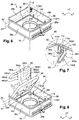
- Each housing 16, 18 comprises a body 24 delimited by four peripheral walls 28a-d.
- the two walls 28a, 28b are parallel to the X, Z plane while the two walls 28c, 28d are parallel to the Y, Z plane.
- the walls 28a and 28b are respectively called front walls 28a and 28b rear.
- This name valid in the example shown in these figures, is no longer relevant in the case where, for example, the assembly is in a vertical position in which the wall 28a is below the wall 28b.
- Each body 24 is also delimited by a bottom 30 parallel to the X, Y plane as represented on the figures 4 , 6 and 8 .
- the four walls 28a, 28b, 28c, 28d and the bottom 30 of each housing give it a rectangular parallelepiped general shape.
- the walls 28a-d delimit, for each housing 16, 18, an opening 34, visible on the figures 4 , 6 and 8 .
- the assembly 14 is shown in the closed position in which the opening 34 of the first housing 16 is closed by the bottom 30 of the second housing 18.
- the opening 34 of the second housing 18 is, in turn, closed by a cover 38
- the first housing 16 as the lower housing and the second housing 18 as the upper housing will be designated hereinafter. with reference to the figures. It is understood that the two housings can be superimposed with their vertical backgrounds and that it is even conceivable that the first housing 16 is in contact with a horizontal face of a support, for example the ceiling of a room, and is located thus above the second housing 18.
- the cover 38 comprises a transparent identification pane 40 of the housing 18 covering an identification space 42 intended to receive, for example, a label.
- a hole 44 for a screw is formed in the cover 38.
- each front wall 28a comprises six orifices 46a-f input and / or output for the passage of one or more cables 13 optical fibers. These orifices are arranged in two groups of three orifices, these groups being arranged on either side of a median longitudinal plane ML of the housing, parallel to the Y, Z plane. Each orifice has a generally circular shape and is provided with a sealing member 48a-f adapted to cooperate with the wall 28a and the cable 13.
- each bottom 30 also comprises fixing means 50a, 50b, extending parallel to the bottom 30, respectively from the front walls 28a and rear 28b, in opposite directions to each other, towards the outside of the housing.
- These fixing means 50a, 50b are intended for fixing the housing on a support, for example a wall.
- the front attachment means 50a comprise a tab 51a with a curved edge having an orifice 52a.
- the rear attachment means 50b comprise a tab 51b of generally rectangular shape having two circular orifices 52b1, 52b2 symmetrical to each other with respect to the plane ML.
- Each orifice 52a, 52b1, 52b2 allows, among other things, the passage of a screw for fixing the housing 16 to the support.
- each rear wall 28b comprises articulation means 54 of the housings 16 and 18 relative to each other.
- These means 54 comprise two pads 56 of generally cylindrical shape arranged symmetrically with respect to the plane ML and protruding with respect to the wall 28b in the direction Y.
- the hinge means 54 also comprise the rear leg 51b.
- the circular orifices 52b1, 52b2 allow the passage of the pads 56 corresponding to the other housing 16, 18.
- the assembly 14 without the cover 38.
- they also include a channel 64 formed in each front wall 28a.
- This channel 64 has a cylindrical shape and passes through the wall 28a of each opening 34 parallel to its main faces to each bottom 30.
- the assembly 14 can thus be fixed to a support by means of a common screw passing through the coaxial channels 64 of the two housings 16, 18.
- each opening 34 is delimited by an edge 66 while each bottom comprises an edge 70.
- each opening edge 66 has a generally U-shaped cross section and comprises a groove 74 in which a sealing member 78 is arranged, for example a crush joint.
- Each bottom edge 70 also includes a groove 78 also having a generally U-shaped cross-section, inverted with respect to that of the edge 66, this section being larger than the section of the opening groove 74.
- the The bottom groove 78 may cover the opening edge 66.
- each bottom groove 78 comprises a rib 82 cooperating with the crush seal 77.
- the edge 66 of the second housing 18 is not covered by the cover 38, the seal 77 is not crushed.
- the assembly comprises means for immobilizing the housings in this relative position where the first housing is open.
- these means comprise between the orifices 52b1, 52b2 of the rear leg 51b a slot 64 formed in the leg 51b and extending parallel to the direction X.
- the immobilizing means also comprise a latch 134 which can be simultaneously received in the slots 64 of the housings 16 and 18.
- the latch 134 comprises a body 136 of generally flat rectangular shape, having two main faces 136a and 136b and two opposite edges 138 and 139 each provided with a relief 142 and 144.
- the relief 142 protrudes from the face 136a.
- the relief 144 comprises, on the one hand, a portion 144a protruding from the face 136a of the same side of the body as the relief 142 and, on the other hand, a portion 144b protruding from the face 136b on the opposite side to part 144a.
- the face 136b has two cheeks 145 perpendicular to the face 136a and disposed on the edges 145a, 145b perpendicular to the edges 138, 139. Each cheek 145 extends over about two thirds of each edge 145a, 145b. The distance between the edge 139 and each 145 plays is equal to the thickness of the rear leg 51b so that this edge is maintained between the relief 144 and each cheek 145.
- Each housing 16, 18 also comprises hinge means 86 for rotating two cassettes 88, 90 for receiving optical fibers.
- These cassettes 88, 90 will be described precisely below with reference to the Figures 13 to 15 .
- These hinge means 86 comprise two pairs 92, 94 of holes 92c, 92d and 94c, 94d, of generally circular shape, formed in each of the walls 28c and 28d, symmetrically with respect to the plane ML.
- Each pair 92 and 94 defines two axes A1 and A2 of rotation of the cassettes.
- the holes 92c, 92d, 94c, 94d are disposed in the half of the housing 16 opposite that comprising the orifices 46a-f input and / or output.
- Each pair 92, 94 is able to receive means of complementary joints of each cassette 88, 90, in this case a pair of fingers 96b, 96c as shown in FIGS. Figures 13 and 15 .
- Each hole 92c and 92d is disposed halfway up each wall 28c, 28d.
- Each hole 94c, 94d is disposed at mid-height between each hole 92c, 92d and the edge 66.
- the pairs 92, 94 are aligned in a direction parallel to the Z direction.
- each cassette 88, 90 is rotatable between an operating position and a maintenance position relative to the bottom 30.
- the cassettes 88, 90 are shown in their maintenance position.
- the first cassette 88 forms an angle of about 50 ° with the bottom 30 and the second cassette 90 forms an angle of about 90 ° with the bottom 30.
- the first and second cassettes 88, 90 are respectively maintained in their maintenance position by holding means 100c, 100d and 102c, 102d, shown in greater detail on the figure 7 .
- These means 100c, 100d and 102c, 102d are arranged symmetrically with respect to the plane ML and comprise studs projecting from the walls 28c, 28d.
- the pads 100c, 100d are oriented to form an angle of approximately 50 ° with the bottom 30 while the pads 102c, 102d are oriented to form an angle of approximately 90 ° with the bottom 30.
- the hinge means 86 comprise guide means for sliding the fingers 96, 98 respectively from the edge 66 to the pairs 92 and 94.
- These guide means each comprise a channel 108, 110 defined by two edges 108a, 108b , 110a, 110b.
- the channel 110 is rectilinear while the channel 108 has an angle between the edge 66 and each hole 92c, 92d.
- bearing means 112 comprise two pairs of ribs 112c1, 112c2, 112d1, 112d2 of generally rectangular shape each protruding respectively with respect to the inner face of each wall 28c, 28d.
- the ribs 112c1, 112d1 are located about a quarter of the length of the housing from the wall 28a.
- the ribs 112c2, 112d2 are located about a quarter of the length of the housing from the wall 28b.
- These ribs 112c1, 112c2, 112d1, 112d2 extend from the bottom 30 of the housing 16 to about one third of the height of each wall 28a, 28d.
- the support means 112 also comprise a pair of reliefs 114a-b respectively allowing the cassettes 88, 90 to be held in the closed position, in particular when the casing 16 is fixed to a vertical wall.
- Each relief 114a, 114b protrudes from a rounded portion of the inner face of the wall 28a including the channel 64.
- the relief 114a is located about two thirds of the height between the bottom 30 and the edge 66.
- the relief 114b is located flush with the opening 34.
- the cassettes 88, 90 give more access than in the operating position to a chamber 116.
- the chamber 116 is delimited by two walls. look at each other, in this case by the cassette 88, the bottom 30 and the walls 28a-d.
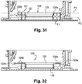
- this chamber 116 of the housing comprises a support 126 for turns.
- This support 126 comprises a portion 118 in one piece with the bottom of the housing and a portion 120 attached removably.
- the portion 118 forms a base of generally cylindrical shape with reference to a main axis S.
- the cylinder is interrupted on one side by an opening. This portion 118 is located substantially in the center of the bottom 30.
- the part 120 forms a spacer and is threaded coaxially on the base 118.
- the spacer 120 comprises a body 121 of generally cylindrical shape having two lower edges 122 and upper 124.
- the lower edge 122 is the edge of the spacer 120 closest to the bottom 30.
- the edge 122 carries a first series of three delimiting members of two distinct locations: E1, called the lower location and E2, called the upper location, of the Room 118. These locations are separate from each other.
- These delimiting members are formed by lower tabs 122a-c extending radially away from the main axis S. These three tabs 122a-c are angularly arranged at 120 ° relative to each other.
- Each delimiting member 122a-c carries, at its end, a radial support member extending axially in the direction Z. In this case, each support member is formed by a lug 123a-c directed towards the Opening 34.
- the tabs 122a-c have different maximum radial dimensions. to facilitate the introduction of the spacer into the chamber 116.
- the tabs 122a and 122b are about twice as long as the tab 122c so that the lugs 123a and 123b extend at distances of the axis S different from that corresponding to the lug 123c.
- the upper edge 124 carries a second series of three members delimiting the lower locations E1 and E2 radially extending away from the main axis S.
- These three legs 124a-c are radially of the same length as the lower leg 122c. They are angularly arranged at 120 ° relative to each other.
- the members 122a-c of the first series, associated with the location E1 are angularly offset about the axis relative to the members 124a-c of the second series, associated with the location E2.
- the members 124a-c are respectively offset by 60 ° with respect to the lower tabs 122a-c in a view along the axis S.
- the delimiting members 122a-c and 124a-c are thus distributed uniformly around of the main axis S of the support 126.
- the removable spacer 120 is held on the base 118 by the cassette 88 when it is in position in the housing.
- support support 126 is able to serve as a common support to the turns of each location.
- the locations E1 and E2 can receive cables comprising a plurality of optical fibers.
- the location E2 can receive one or more bare optical fibers.
- the locations E1 and E2 are thus able to receive turns of optical fiber so that these turns extend respectively in planes P1 and P2 different from each other.
- the locations E1 and E2 follow one another along the main axis S. In this case, the lower location E1 is delimited by the bottom 30 and the lower legs 122a-c, between these, while the upper location E2 is delimited by the lower tabs 122a-c and the upper tabs 124a-c therebetween.
- This support 126 allows on the one hand, the radial support of the turns 128 through the cylindrical body 121 of the spacer, the base 118 and the pins 123a-c and, on the other hand, the axial support of the turns 128 thanks to the tabs 122a-c, 124a-c.
- the support 126 defines a minimum radius of curvature of the turns 128.
- the base 118 and the body 121 respectively define the minimum radius of curvature of the lower location E1 and the upper location E2 while the walls 28c, 28d and the pins 123a-c respectively define a maximum radius of curvature of the lower location E1 and the upper location E2.
- the location E2 generally allows the support of a turn formed by a fiber intended to pass into the upper housing and to be connected to a cassette of this upper housing 18 while the location E1 allows the support of a coil formed by a fiber to be connected to a cassette of the lower housing 16.
- these functions of the locations E1 and E2 can be interchanged.
- the bottom 30 of the latter has a through hole 130.
- This orifice has a generally oblong shape and extends in the half of the bottom 30 closest to the edge 70 of the second housing 18 in contact with the edge 66 of the opening 34 of the housing 16 in the open position.
- the orifice 130 extends over a little less than half the transverse width of the bottom 30.
- Another orifice 132 symmetrical with the orifice 130 with respect to the plane ML, is formed in the bottom 30. In the example represented on the figure 10 , the orifice 132 is closed by a breakable lid 133.
- a cassette 88 identical to the cassette 90.
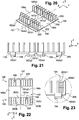
- This cassette 88 has a generally rectangular shape and comprises a bottom 146 from which 148a-d walls protrude perpendicularly to the bottom 146. Each wall 148a-d extends respectively opposite each wall 28a-d. Each wall 148c, 148d has at its end opposite the wall 148a, the finger 96c, 96d. The fingers 96c, 96d define an axis of rotation of the cassette 88 coincides with the axis of rotation A1 defined by the holes 92c, 92d. The wall 148d is set back from this axis of rotation so that when the cassette is mounted on the housing 16 as shown in FIG. figure 8 an opening 140 is formed between the cassette and the wall 28b. The axis of rotation A1 of the cassette intercepts this opening 140 and the orifice 130 is located at the right of this opening 140.
- the cassette 88 comprises two zones 150 and 152 separated from each other by a wall 153 projecting from the bottom 146 and extending in the direction Z.
- the wall 153 is substantially parallel to the plane X, Z and is located about halfway between the walls 148a and 148b.
- the zone 150 comprises guide means 154 of at least one fiber, in particular arranged to give the fiber a radius of curvature greater than a predetermined radius of curvature, below which the transmission of the signal could be degraded. These means are arranged to make it possible to arrange the or each fiber so that its direction of winding changes along the fiber and / or so that the fiber crosses at least once, and / or at least two turns of the fiber. fiber stretch side by side.
- the guide means 154 comprise two drums 156 and 158 arranged symmetrically to each other with respect to the plane ML.
- Each drum 156 and 158 comprises walls 160 projecting from the bottom 146 and extending in the direction Z.
- the walls 160 are arranged around a center C1, C2 of the drum 156, 158 and consist of an alternation of four convex walls 160a1-4 and four concave walls 160b1-4 around the center C1, C2.
- the concave walls 160b1, 160b2, 160b4 of the drum 156 are respectively facing walls 148c, 148a, 148b.
- the concave walls 160b1, 160b2, 160b4 of the drum 158 are respectively facing the walls 148d, 148a, 148c.
- the walls 160b3 of the drums 156 and 158 are opposite one another.
- the convex walls 160a1-4 are directed towards the four corners of the cassette 88.
- the guide means 154 also comprise two walls 162c and 162d protruding from the bottom 146, arranged symmetrically to each other with respect to the plane ML and each having an arcuate shape.
- the center of curvature of each wall 162c, 162d is located on the center side of the housing 16.
- Each wall 162c, 162d is arranged respectively between each wall 148c, 148d and each drum 156, 158.
- the guide means 154 comprise means for vertically guiding an optical fiber.
- These guide means comprise tabs 164 having a generally point-like shape extending substantially parallel to the bottom 146 of the cassette 88.
- a tab 164a extends from the wall 160b3 of the drum 156 to the drum 158 without touching it. here, the arrow pointing to the drum 158.
- a tab 164b extends from the wall 153, in the middle thereof in the direction X, towards the wall 148b, the arrow pointing to the wall 148b.
- a tab 164c extends from the wall 148b, in the middle thereof in the X direction, towards the wall 153, the arrow pointing to the wall 153.
- tabs 164d and 164e located on both sides other of the tab 164c, symmetrically with respect to the plane ML, extend similarly to this tab 164c and have homothetically reduced dimensions.
- tabs 164f and 164g arranged symmetrically with respect to the plane ML, respectively extend in the Y direction from the middle of the walls 148c and 148d, towards the walls 160b1, the arrow pointing towards these walls 160b1.
- the zone 150 also comprises two combs 166 for holding the optical fibers, each provided with a counter-comb 168 movable relative to the comb 166 to close it.
- the combs 166 are arranged symmetrically with respect to the plane ML, between the walls 162c, 162d and the walls 148b, 148c, 148d.
- Each comb 166 extends from the vicinity of the corresponding corner of the housing 16 towards each drum 156, 158.
- each comb 166 comprises four recesses 168a1-4 alternating with three teeth 168b2-4, and two ends 168b1 and 168b5 of the comb.
- the counter-comb 168 is rotatably mounted around a shaft 170 received in a housing 172 formed in the end 168b5.
- the counter-comb 168 is locked in a closed position of the recesses 168a1-4 thanks to conventional elastic locking means 174 forming a clip formed in the end 168b1 and against the comb 168 opposite the axis 170 .
- the area 152 of the cassette 88 includes a housing 176 for a splice holder 178 removably attached to the cassette.
- This housing 176 has a rectangular shape corresponding to the general shape of a base 179 of the splice holder 178.
- the zone 152 comprises orifices 180 arranged in three lines parallel to the direction Y when the cassette 88 is in the closed position.
- Two lines 180a, 180b are arranged on either side of the plane ML.
- Each line 180a, 180b respectively comprises three orifices 180a1-3, 180b1-3 for accommodating clips 182a1-3, 182b1-3 of the splice support 178, visible on the figure 17 .
- a line 180c also accommodates centering studs 184 of the support 178.
- the splice holder 178 comprises two portions 186a and 186b which can be separated from each other along a predetermined line 187.
- the two portions 186a, 186b are symmetrical about the predetermined line 187.
- the support is breakable thanks to, on the one hand, two recesses 187a1, 187a2 and, on the other hand, three zones of necking 187b1, 187b2, 187b3 alternating with the recesses 187a1, 187a2.
- the recesses and the zones of necking materialize the predetermined line 187.
- the splice support 178 comprises two retaining zones 188, 190 of the optical fibers on either side of a splice zone 192. Each of these zones 188 , 190 intersects in the middle line 187.
- Each holding zone 188, 190 respectively comprises holding means 196a, 196b of an optical fiber comprising a plurality of pairs of pads.
- the pairs of studs delimit several channels 194 leading to the splice zone 192.
- each channel 194 is delimited by first, second and third pairs of pads, respectively referenced 200, 202 and 204 on each side of the splice zone 192 and aligned in the X direction starting from the edges 205, 206 of the base 179 parallel to the Y direction to the splice area 192.
- the support 178 also comprises means 198 for locking the optical fibers in the holding means 196a, 196b.
- These locking means 198 belong to the holding means 196a, 196b and are capable of blocking several fibers independently of each other in the common holding means 196a, 196b to said fibers.
- the locking means comprise reliefs carried by at least one of the pads of each pair.
- a first stud 200a for holding the first pair 200 comprises a relief 200a1 positioned at about two thirds of the height of the stud 200a with respect to the base 179 and pointing towards the inside of the channel.
- a second stud 202a for holding the second pair 202 associated with the same channel 194 has a relief 202a1, positioned at the top of the pad 202a, the second holding pad 202a being disposed on one side of the channel 194 opposite that of the first pad 200a.
- the relief 202a1 also points towards the interior of the channel 194.
- a third stud 204a for holding the third pair 204 comprises a blocking relief 204a1.
- the support relief 204a1 is disposed on the same side of the channel 194 as that of the first stud 200a.
- the pad 204 has a height equal to about one third of the height of the pads 200a and 202a.
- the relief 204a1 is disposed at the top of the pad 204 and points inwardly of the channel 194.
- the reliefs are not oriented in the same way. Indeed, on the part 186a designated as being closest to the wall 153, illustrated on the Figures 13 and 15 , the reliefs 200a1, 204a1 point towards the wall 153 while the reliefs 202a1 point in the opposite direction to the wall 153. On the part 186b designated as the farthest from the wall 153 on the figure 15 , the reliefs 200a1, 204a1 point in the opposite direction to the wall 153 while the reliefs 202a1 point to the wall 153. It will also be noted that the channels adjacent the edges of the support 178 comprise a reduced number of pads. In this case, these adjacent channels are delimited by only two pairs of pads.
- each guide channel 194 comprises at least two support protrusions of each fiber FO.
- the reliefs differ from each other two by two, by the following parameters: their height relative to the base of the support, the side of the channel where they are located, and the pair of studs that carry them. These studs and reliefs make it possible to maintain up to three FO fibers in the same channel, independently of one another above each other and parallel to each other, as shown in FIG. figure 19 .
- the support 178 is intended to receive fusion splices.
- each channel 194 is delimited by first and second pairs of pads, respectively referenced 200, 202 aligned in the X direction starting from the edges 205, 206 of the base 179 towards the splice area 192.
- a first holding pad 200b of the first pair 200 comprises a relief 200b1 positioned at the top of the pad 200b and pointing towards the inside of the channel 194.
- a second pad 202b for holding the second pair 202 associated with the same channel 194, comprises a relief 202b1, positioned at the top of the pad 202b, this second holding pad 202a being disposed on the same side of the channel 194 as that of the first pad 200b.
- the relief 202b1 also points to the interior of the channel 194.
- the pads 200b and 202b all have equal heights.
- the studs that they are arranged on the part 186a or 186b of the support 178, have reliefs all oriented in the same way, in this case to the wall 153.
- the studs and reliefs can maintain up to two fibers in the same channel.
- Both media variants can be used to connect different optical fibers with different types of splices.
- each support being breakable, it is possible to arrange side by side a part resulting from the separation from the other part of the support according to Figures 16 to 19 along the predetermined line and another part resulting from the separation from the other part of the carrier according to figure 20 to 23 along the predetermined line.
- Each of these parts can then receive respectively fusion splices and mechanical splices.
- the housing may comprise at least part of a support and / or a support.
- each inlet 46a, 46b, 46c, 46d inlet and / or outlet for the passage of an optical fiber cable is provided with its corresponding sealing member 48a-d in accordance with the figure 26 .
- each member 48a-d is symmetrical of revolution and comprises a wide portion 208 extended by a narrow portion 210 of generally cylindrical shape and of smaller external radius.
- the organs are hollow. Their inner radius is constant over their entire length so that the cable passing through each sealing member 48a-d matches their inner walls 208a, 210a respectively.
- the outer surface 208b of the body 210 has a groove 212 for positioning each sealing member in the corresponding orifice 46a-d.
- each member 48a-d comprises a sealing film 214 extending in a passage space of the cable in the member, defined by the inner wall 208a of the portion 208 from the wall 208a.
- the film 214 is precut.
- the sealing member may comprise only one body 208.
- the sealing member 48a, 48b, 48c, 48d comprises a partial extension 215 extending in the opposite direction to the extension 210. This extension 215 makes it possible to support the cable before passing through the member.
- the extension 210 is sandwiched between two parts 216 and 218 for fixing the cable.
- the sealing member 48a-d is in accordance with the variant described with reference to FIG. figure 27 .
- the cable is directly gripped in contact with the parts 216 and 218.
- the portion 216 is in one piece with the housing 16 while the portion 218 is attached to the housing 16.
- the part reported 218 has a general shape of bridge with three arches 217a-c separated from each other by pillars 218a-d.
- the portion 218 comprises, between the arches of the pairs of arches 217a, 217b and 217b, 217c, a hole 220b, 220c of generally cylindrical shape formed in each pillar 218b and 218c.
- the end pillars 218a and 218d are extended by studs 220a and 220d.
- Part 216 has a shape complementary to part 218, namely a general shape of bridge with three arches separated from each other by pillars.
- Part 216 comprises, between the arches of the two pairs of arches, a generally cylindrical stud extending each pillar and intended to penetrate into the corresponding orifice 220b, 220c of part 218.
- the pillars at the ends of the bridge have orifices intended to receive the studs 220a and 220d of the part 218.
- the housings 16, 18 according to the first embodiment of the invention make it possible to implement an installation method whose main aspects related to the invention will be described.
- the first housing 16 or lower housing is fixed on a support, for example a wall of the building by means of screws that are passed through the orifices. 52a, 52b1 and 52b2. Then, the supply cable 13 is passed through the orifice 46a provided with the sealing member 48a.
- the supply cable is too large, it is divided into two parts that can pass, for example, in the orifices 46a and 46b, each provided with members 48a and 48b.
- the cable 13 comprises a number of optical fibers FO too large for the connection to be made in the single housing 16, this time divides into the housing these optical fibers FO into two beams.
- the first beam is wound in the slot E1, passed through the openings 140 corresponding to the cassettes 88, 90 of the housing 16, and then coiled on the cassettes 88, 90.
- the second beam is associated with the second housing as indicated below.
- the second housing 18 is installed on the first. Before or after this step, the building wire is identified and its FO fibers are passed through the front openings 46a and 46b of the housing 18, each provided with members 48a and 48b.
- the latch 134 makes it possible to immobilize the housings 16 and 18 in this position.
- the orifice 130 of the bottom of the second housing is then released by removing the lid 133 and a first fiber bundle FO of the building cable 15 is passed through this orifice 130 from the second housing to the first housing.
- the first bundle comprising fibers to be connected by so-called mechanical splices and by fusion, is separated, on the one hand, from one another, two parts 186a and 186b of the support 178 in accordance with Figures 16 to 19 and, on the other hand, one of the other, two parts 186a and 186b of the support 178 in accordance with Figures 20 to 23 . Then, two parts 186a of the two supports are associated with each of the casettes 88 and 90.
- the first bundle of the building cable 15 is connected to the first bundle of the add-on cable 13, fiber-to-fiber, on the associated splice supports 178 of the cassettes 88, 90 of the lower case 16.
- the second bundle of the supply cable 13 is wound in the location E2 of the lower case 16.
- the turns of the fibers of the first bundle of the cable 13 intended to be connected in the lower case 16 are received in the lower slot E1 while the turns of the fibers of the second bundle of the cable 13 intended to be connected in the upper housing 18 are received in the upper location E2. It was thus taken care to have the turns belonging to separate fibers in the respective locations of the chamber 116.
- the second beam is passed through the opening 140 of this housing, through the opening 130 of the bottom of the upper housing, and through the opening 140 of the housing.
- the FO fibers of the second bundle of the adduction cable 13 are connected to the FO fibers of the second bundle of the building cable 15, fiber to fiber, in this second housing, on the cassettes 88, 90 in a similar way to the connection between the first bundle of the building cable 15 and the first bundle of the adduction cable 13.
- the latch 134 is then removed to position the assembly in the closed position. To do this, the opening 34 of the lower housing 16 is closed with the bottom 30 of the upper housing 18. Then, the opening 34 of the upper housing 18 is closed with the cover 38.
- the housings 16, 18 according to the first embodiment of the invention also make it possible to implement a maintenance method whose main features related to the invention will be described.
- An installer removes the cover 38 and performs maintenance operations in the upper case 18, if necessary by lifting the cassette. Once these are done, he moves the upper housing 18 relative to the lower housing 16 through the hinge means 54, thus passing the assembly 14 from its closed position to its open position. By moving the upper housing 18 relative to the lower housing 16, the radius of curvature of the turns of the optical fibers received in the location E2. The installer then carries out the maintenance operations in the lower case 16, if necessary by lifting the cassette or cassettes. By lifting one or more cassettes, the radius of curvature of the optical fiber turns received in the slot E1 is varied.
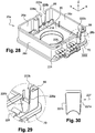
- the housing 20a comprises on each of the front walls 28a and rear 28b, an opening 222a and 222b entry and exit cable.
- these openings have a general shape of "U" opening at the upper edge 66.
- the front opening 222a is located opposite an arch of the part 216 so that a cable passing through the opening 222a can be enclosed between the parts 216 and 218.
- the rear wall 28b also comprise orifices 224 for exiting an optical fiber cable provided with sealing members 226 similar to the sealing members shown in FIG. figure 2 .
- a slide 227 shown in FIG. figure 30 has a shape complementary to that of the orifice provided with the cable 15. This slide has two edges 227a and 227b slidable in complementary slides 228a, 228b formed in each wall 28a and 28b.
- the housing 20a makes it possible to cross the optical fiber cable 15 in the housing 20a by deriving from the cable 15 some of its optical fibers FO towards the dwellings 10a1, 10a2. These FO fibers may, where appropriate, form turns in the locations E1, E2 of the support 126, then pass through the orifices 224. The remainder of the cable is then directed to the next bearing.
- the cable 15 can also enter the housing through the opening 222a without coming out through the opening 222b, as shown at the level of the bearing 11d on the figure 1 .
- the housing 20a according to the second embodiment of the invention makes it possible to implement an installation method whose main aspects related to the invention will be described.
- the building cable 15 Upon arrival on the first landing, the building cable 15 comprises at least 8 optical fibers for homes 10a1, 10a2, 10b1, 10b2, 10c1, 10c2, 10d1, 10d2.
- the housing 20a is fixed on a support.
- the slider 227 is removed from each of the walls 28a, 28b of the housing 20a.
- the building cable 15 is passed through the opening 222a.
- the cables 15 are derived from two FO fibers for dwellings 10a1 and 10a2. Then, the turns corresponding to these fibers are formed in the locations of the support 126. These FO fibers are pulled out by two orifices 224 each provided with the sealing member 226.
- the cable 15 is taken out of the casing with the fibers they remain through the orifice 222b and replace the corresponding slider.
- the housing may have various sizes.
- the dimensions of the housing may take values ranging from decimeter to meter.
- housing according to the invention may have a generally cylindrical shape, ovoid or other without departing from the scope of the invention.
- connection box for optical fibers comprising a removably attached part, this part being able to serve as support for turns of optical fiber, this part comprising means for delimiting a location adapted to receive turns of optical fiber.
- These boxes will not necessarily include separate locations capable of receiving turns of optical fiber so that they extend in different planes from each other, nor necessarily a support able to serve as common support turns from each location.
Description
L'invention concerne le raccordement des fibres optiques.The invention relates to the connection of optical fibers.
Elle s'applique en particulier, mais non exclusivement, au raccordement de fibres optiques dans des parties communes d'un ensemble d'habitations, par exemple un immeuble, notamment pour la fourniture de services de télécommunication haut-débit.It applies in particular, but not exclusively, to the connection of optical fibers in common parts of a housing complex, for example a building, in particular for the provision of high-speed telecommunications services.
Le raccordement de fibres optiques est généralement localisé dans un boîtier. Un tel boîtier comprend plusieurs cassettes de raccordement distinctes sur lesquelles les fibres sont lovées et raccordées, par exemple par épissure.The optical fiber connection is generally located in a housing. Such a housing comprises several separate connection cassettes on which the fibers are coiled and connected, for example by splicing.
On connaît déjà dans l'état de la technique un boîtier dans lequel les cassettes de raccordement sont superposées les unes aux autres et montées mobiles par rapport à un fond du boîtier. La cassette la plus proche du fond délimite, avec ce fond, une chambre. Cette chambre comprend des moyens de réception de spires de fibres optiques permettant de rassembler toutes les fibres dans un même faisceau. Ces moyens comprennent, par exemple, des colliers de serrage des fibres.Already known in the state of the art a housing in which the connecting cassettes are superimposed on each other and mounted movable relative to a bottom of the housing. The cassette closest to the bottom delimits, with this background, a chamber. This chamber comprises means for receiving turns of optical fibers making it possible to gather all the fibers in the same bundle. These means include, for example, fiber clamps.
Une telle configuration est notamment exposée dans le
Lors des opérations d'installation et de maintenance du boîtier, l'installateur déplace les cassettes les unes par rapport aux autres, ce qui a pour effet de solliciter chacune des fibres raccordées sur les cassettes déplacées. En particulier, lorsque l'installateur souhaite accéder à une cassette donnée recouverte par d'autres cassettes, il doit déplacer ces autres cassettes, sollicitant ainsi les fibres du faisceau raccordées sur des cassettes non déplacées. Cette sollicitation peut endommager une des fibres voire entraîner sa rupture, notamment au niveau d'une épissure, et causer une interruption du service particulièrement indésirable.During the installation and maintenance of the housing, the installer moves the cassettes relative to each other, which has the effect of soliciting each of the fibers connected to the cassettes moved. In particular, when the installer wishes to access a given cassette covered by other cassettes, he must move these other cassettes, thereby soliciting the beam fibers connected to unmoved cassettes. This stress can damage one or even break the fiber, especially at a splice, and cause a particularly undesirable service interruption.
L'invention a pour but de fournir un boîtier permettant de réduire la sollicitation des fibres lorsque des opérations sont effectuées dans le boîtier.The object of the invention is to provide a housing for reducing the stress on the fibers when operations are performed in the housing.
A cet effet, l'invention a pour objet un boîtier de raccordement pour fibres optiques incluant les éléments énoncés dans la partie caractérisante de la revendication 1.To this end, the subject of the invention is a connection box for optical fibers including the elements set forth in the characterizing part of claim 1.
Les emplacements du boîtier selon l'invention permettent de solliciter les fibres reçues dans un même emplacement indépendamment des fibres reçues dans les autres emplacements. De plus, si le boîtier comprend des cassettes de raccordement, le boîtier selon l'invention permet de fournir aux fibres un support d'appui commun situé hors de celles-ci.The locations of the housing according to the invention make it possible to stress the fibers received in the same location independently of the fibers received in the other locations. In addition, if the casing comprises connecting cassettes, the casing according to the invention makes it possible to provide the fibers with a common support support situated outside of them.
De tels organes permettent aux spires de s'étendre avec des rayons de courbure variables par rapport à l'axe principal. Ainsi, chaque emplacement peut recevoir plusieurs spires de plusieurs fibres, les spires d'une même fibre pouvant avoir des rayons de courbure adaptés à la sollicitation envisageable pour la fibre correspondante.Such members allow the turns to extend with radii of curvature variable with respect to the main axis. Thus, each location can receive several turns of several fibers, the turns of the same fiber may have radii of curvature adapted to the solicitation possible for the corresponding fiber.
De façon optionnelle, au moins deux des organes de délimitation présentent des dimensions radiales maximales différentes entre eux. Selon d'autres caractéristiques optionnelles du boîtier selon l'invention :
- les organes de délimitation sont répartis de façon uniforme autour de l'axe. Par répartition uniforme, on fait référence à une répartition dans laquelle le décalage angulaire entre les organes successifs est constant. La répartition uniforme des organes de délimitation permet d'assurer un maintien axial régulier, autour de l'axe, des spires de fibre optique dans chaque emplacement. Les organes ainsi répartis évitent que les spires ne débordent localement dans un autre emplacement.
- les organes de délimitation forment deux séries d'organes associées aux emplacements respectifs, les organes de l'une des séries étant décalés angulairement autour de l'axe par rapport à ceux de l'autre série. Des tels organes permettent de maintenir axialement, de façon efficace, les spires de fibre optique dans au moins un des emplacements délimités par les organes des deux séries. Avantageusement, les organes de l'une des séries s'étendent entre ceux de l'autre série en vue axiale du support.
- the delimiting members are distributed uniformly about the axis. By uniform distribution, reference is made to a distribution in which the angular offset between the successive members is constant. The uniform distribution of the delimiting members ensures a regular axial retention around the axis of the optical fiber turns in each location. The organs thus distributed prevent the turns from overflowing locally in another location.
- the delimiting members form two series of members associated with the respective locations, the members of one of the series being angularly offset about the axis relative to those of the other series. Such members can maintain axially, effectively, the optical fiber turns in at least one of the locations defined by the organs of the two series. Advantageously, the members of one of the series extend between those of the other series in axial view of the support.
Avantageusement, le boîtier comprend des organes d'appui radial s'étendant axialement par référence à un axe principal du support, par exemple à des distances de l'axe différentes l'une de l'autre pour au moins deux des organes d'appui, les organes d'appui étant de préférence portés par les organes de délimitation.Advantageously, the housing comprises radial support members extending axially with reference to a main axis of the support, for example at distances from the axis that are different from one another for at least two of the support members. , the support members being preferably carried by the delimiting members.
Ces organes d'appui permettent de maintenir radialement les spires dans chaque emplacement en limitant leur rayon de courbure, que ce soit par une limite inférieure ou supérieure.These support members are used to maintain radially the turns in each location by limiting their radius of curvature, whether by a lower or upper limit.
Un tel support permet, lorsque la fibre optique est sollicitée, d'assurer que cette dernière ne prend pas un rayon de courbure inférieur à un rayon de courbure prédéterminé en dessous duquel la qualité de la transmission future du signal dans la fibre est fortement dégradée.Such a support makes it possible, when the optical fiber is stressed, to ensure that the latter does not take a radius of curvature less than a predetermined radius of curvature below which the quality of the future transmission of the signal in the fiber is greatly degraded.
De plus, dans le cas où l'installateur sollicite une fibre formant les spires dans un emplacement donné, ces spires peuvent se resserrer et/ou se desserrer autour du support.In addition, in the case where the installer is requesting a fiber forming the turns in a given location, these turns can be tightened and / or loosen around the support.
Dans le cas d'une sollicitation où les fibres se resserrent, celles-ci peuvent présenter, le cas échéant, le rayon de courbure minimal, et permettent de fournir une sur-longueur de fibre.In the case of a stress where the fibers are tightened, they may have, where appropriate, the minimum radius of curvature, and can provide an over-length of fiber.
L'invention est notamment applicable à un ensemble de deux boîtiers de raccordement et d'une fibre optique, dans lequel au moins un des boîtiers est tel que défini ci-dessus et dans lequel la fibre optique forme une spire dans un des emplacements de la chambre et passe de ce boîtier à l'autre boîtier.The invention is particularly applicable to a set of two connection boxes and an optical fiber, wherein at least one of the housings is as defined above and wherein the optical fiber forms a turn in one of the locations of the room and pass from this housing to the other housing.
Dans un tel ensemble, la fibre optique passant d'un boîtier à l'autre est sollicitée dès que les boîtiers sont déplacés l'un par rapport à l'autre. Le boîtier dans lequel la fibre optique forme la spire permet de recevoir d'une part, dans un emplacement, les fibres destinées à êtres raccordées dans le boîtier comprenant le support et, d'autre part, dans un autre emplacement distinct, la fibre passant dans l'autre boîtier, et éventuellement destinée à être raccordée dans cet autre boîtier. Ainsi, le déplacement des deux boîtiers l'un par rapport à l'autre ne sollicite que la fibre passant entre ces deux boîtiers.In such an assembly, the optical fiber passing from one housing to the other is requested as soon as the housings are moved relative to each other. The casing in which the optical fiber forms the coil makes it possible to receive, on the one hand, in one location, the fibers intended to be connected in the housing comprising the support and, on the other hand, in another distinct location, the fiber passing through. in the other case, and eventually intended to be connected in this other housing. Thus, moving the two housings relative to each other only solicits the fiber passing between these two housings.
L'invention sera mieux comprise à la lecture de la description qui va suivre, donnée uniquement à titre d'exemple non limitatif et faite en se référant aux dessins dans lesquels :
- la
figure 1 est une représentation schématique d'un ensemble d'habitations comprenant plusieurs boîtiers et un ensemble selon l'invention ; - la
figure 2 est une vue en perspective d'un ensemble de premier et deuxième boîtiers selon un premier mode de réalisation de l'invention montrant des orifices d'entrée et/ou de sorties d'un câble ; - la
figure 3 est une vue en perspective de l'ensemble de lafigure 2 montrant des moyens d'articulation ; - la
figure 4 est une vue en coupe selon le plan IV-IV de l'ensemble de lafigure 2 dans lequel le deuxième boîtier est dépourvu de couvercle ; - la
figure 5 est un agrandissement de la zone V de lafigure 4 ; - la
figure 6 est une vue d'un boîtier selon le premier mode de réalisation de l'invention démuni de son couvercle montrant une partie d'un support d'appui pour des spires de fibre optique; - la
figure 7 est une vue agrandie de la zone VII de lafigure 6 ; - la
figure 8 est une vue en perspective du boîtier de lafigure 6 comprenant deux cassettes en position ouverte ; - la
figure 9 est une vue en perspective de l'ensemble de lafigure 4 en position ouverte ; - la
figure 10 est une autre vue en perspective de l'ensemble de lafigure 6 montrant un support d'appui pour des spires de fibre optique ; - la
figure 11 est une vue en perspective d'une partie amovible du support d'appui de lafigure 10 ; - la
figure 12 est une vue en perspective d'un organe d'immobilisation de l'ensemble de lafigure 10 ; - la
figure 13 est une vue en perspective d'une des cassettes de lafigure 8 ; - la
figure 14 est une vue agrandie de la zone XIV de lafigure 13 ; - la
figure 15 est une vue de dessus de la cassette de lafigure 13 ; - la
figure 16 est une vue en perspective d'un support d'épissure ; - les
figures 17 et 18 sont des vues latérale et de dessus du support de lafigure 16 ; - la
figure 19 est une vue agrandie d'un détail de lafigure 17 dans laquelle on a représenté des fibres optiques ; - les
figures 20 à 23 sont des vues analogues auxfigures 16 à 19 illustrant une variante du support d'épissure; - la
figure 24 est une autre vue en perspective du boîtier de lafigure 8 montrant les orifices d'entrée et/ou de sorties du câble ; - la
figure 25 est une vue de face d'une partie des moyens de fixation du câble du boîtier de lafigure 24 ; - la
figure 26 est une vue en perspective d'un organe d'étanchéité du boîtier de lafigure 24 ; - la
figure 27 est une vue en perspective d'une variante de l'organe d'étanchéité représenté sur lafigure 24 . - la
figure 28 est une vue en perspective d'un boîtier selon un deuxième mode de réalisation de l'invention ; - la
figure 29 est une vue agrandie de la zone XXIX de lafigure 2 ; - la
figure 30 est une vue d'un coulisseau d'obturation d'un orifice d'entrée et/ou de sortie d'un câble du boîtier de lafigure 28 ; - la
figure 31 est une vue en coupe du boîtier inférieur de lafigure 10 ; - la
figure 32 est une vue analogue à lafigure 31 illustrant une variante du support d'appui.
- the
figure 1 is a schematic representation of a set of dwellings comprising a plurality of housings and an assembly according to the invention; - the
figure 2 is a perspective view of a set of first and second housings according to a first embodiment of the invention showing inlet and / or outlet ports of a cable; - the
figure 3 is a perspective view of the whole of thefigure 2 showing articulation means; - the
figure 4 is a sectional view along plane IV-IV of the whole of thefigure 2 wherein the second housing has no lid; - the
figure 5 is an enlargement of the V zone of thefigure 4 ; - the
figure 6 is a view of a housing according to the first embodiment of the invention without its cover showing part of a support for optical fiber turns; - the
figure 7 is an enlarged view of zone VII of thefigure 6 ; - the
figure 8 is a perspective view of the case of thefigure 6 comprising two cassettes in the open position; - the
figure 9 is a perspective view of the whole of thefigure 4 in open position; - the
figure 10 is another perspective view of the whole of thefigure 6 showing a support for optical fiber turns; - the
figure 11 is a perspective view of a removable portion of the support support of thefigure 10 ; - the
figure 12 is a perspective view of an immobilizer of the whole of thefigure 10 ; - the
figure 13 is a perspective view of one of the cassettes of thefigure 8 ; - the
figure 14 is an enlarged view of the XIV zone of thefigure 13 ; - the
figure 15 is a top view of the tape of thefigure 13 ; - the
figure 16 is a perspective view of a splice holder; - the
Figures 17 and 18 are side and top views of the bracket of thefigure 16 ; - the
figure 19 is an enlarged view of a detail of thefigure 17 in which optical fibers are represented; - the
Figures 20 to 23 are views similar toFigures 16 to 19 illustrating a variant of the splice holder; - the
figure 24 is another perspective view of the case of thefigure 8 showing the inlet and / or outlet ports of the cable; - the
figure 25 is a front view of a part of the cable fixing means of the housing of thefigure 24 ; - the
figure 26 is a perspective view of a sealing member of the housing of thefigure 24 ; - the
figure 27 is a perspective view of a variant of the sealing member shown in FIG.figure 24 . - the
figure 28 is a perspective view of a housing according to a second embodiment of the invention; - the
figure 29 is an enlarged view of the XXIX area of thefigure 2 ; - the
figure 30 is a view of a shutter slide of an inlet and / or outlet of a cable of the housing of thefigure 28 ; - the
figure 31 is a sectional view of the lower housing of thefigure 10 ; - the
figure 32 is a view similar to thefigure 31 illustrating a variant of the support support.
On a représenté sur la
Le réseau 12 comprend un ensemble 14 de deux boîtiers identiques 16, 18, et un câble 13 selon l'invention, le câble 13 pénétrant dans le boîtier 16. Chaque boîtier 16, 18 est conforme à un premier mode de réalisation de l'invention, dans lequel pénètre le câble 13. Chaque boîtier 16, 18 est appelé boîtier de pied d'immeuble. L'ensemble 14 permet de raccorder le câble d'adduction 13 à un câble d'immeuble 15 comprenant également une pluralité de fibres optiques. Le câble d'immeuble 15 relie les boîtiers 16, 18 à des boîtiers 20a-d disposés respectivement sur chaque palier 11a-d. Chaque boîtier 20a-d, appelé boîtier de palier, est conforme à un deuxième mode de réalisation de l'invention. Chaque boîtier 20a-d est respectivement relié, en l'espèce, à deux boîtiers d'habitation 20a1, 20a2, 20b1, 20b2, 20c1, 20c2, 20d1, 20d2 des habitations 10a1, 10a2, 10b1, 10b2, 10c1, 10c2, 10d1, 10d2 du palier correspondant par une fibre optique FO. En variante, chaque boîtier 20a-d pourra être relié à un ou plus de deux boîtiers d'habitation. Enfin, chaque boîtier d'habitation est respectivement relié à des moyens tels que des terminaux 22a1, 22a2, 22b1, 22b2, 22c1, 22c2, 22d1, 22d2. Ces terminaux peuvent comprendre par exemple des moyens de réception, de décodage et de traitement de signal haut débit ou très haut débit pour des applications de type internet, téléphonie, télévision etc. au sein de chaque habitation 10a1, 10a2, 10b1, 10b2, 10c1, 10c2, 10d1, 10d2.The
On a représenté sur les
Chaque boîtier 16, 18 comprend un corps 24 délimité par quatre parois périphériques 28a-d. Les deux parois 28a, 28b sont parallèles au plan X,Z alors que les deux parois 28c, 28d sont parallèles au plan Y,Z. En référence aux
Les parois 28a-d délimitent, pour chaque boîtier 16, 18, une ouverture 34, visible sur les
Le couvercle 38 comprend une vitre transparente d'identification 40 du boîtier 18 recouvrant un espace d'identification 42 destiné à recevoir, par exemple, une étiquette. Un trou 44 pour une vis est ménagé dans le couvercle 38.The
Comme représenté sur la
En référence à la
Comme représenté sur la
On a représenté sur la
En référence aux
On a représenté sur les
L'ensemble comprend des moyens d'immobilisation des boîtiers dans cette position relative où le premier boîtier est ouvert. En l'espèce, ces moyens comprennent entre les orifices 52b1, 52b2 de la patte arrière 51 b une fente 64 ménagée dans la patte 51 b et s'étendant parallèlement à la direction X. Les moyens d'immobilisation comprennent aussi un verrou 134 pouvant être reçu simultanément dans les fentes 64 des boîtiers 16 et 18. Comme représenté sur la
Chaque boîtier 16, 18 comprend également des moyens d'articulation 86 en rotation de deux cassettes 88, 90 pour la réception de fibres optiques. Ces cassettes 88, 90 seront décrites précisément plus bas en référence aux
Comme représenté sur la
Dans la position de maintenance, la première cassette 88 forme un angle d'environ 50° avec le fond 30 et la deuxième cassette 90 forme un angle d'environ 90° avec le fond 30. Les première et deuxième cassettes 88, 90 sont respectivement maintenues dans leur position de maintenance par des moyens de maintien 100c, 100d et 102c, 102d, représentés plus en détail sur la
En référence aux
Comme illustré sur les
Comme représenté également sur la
Le bord inférieur 122 est le bord de l'entretoise 120 le plus proche du fond 30. Le bord 122 porte une première série de trois organes de délimitation de deux emplacements distincts : E1, appelé emplacement inférieur et E2, appelé emplacement supérieur, de la chambre 118. Ces emplacements sont séparés l'un de l'autre. Ces organes de délimitation sont formés par des pattes inférieures 122a-c s'étendant radialement en s'éloignant de l'axe principal S . Ces trois pattes 122a-c sont angulairement disposés à 120° l'une par rapport à l'autre. Chaque organe de délimitation 122a-c porte, à son extrémité, un organe d'appui radial s'étendant axialement selon la direction Z. En l'espèce, chaque organe d'appui est formé par un ergot 123a-c dirigé vers l'ouverture 34. Les pattes 122a-c présentent des dimensions radiales maximales différentes. de façon à faciliter l'introduction de l'entretoise dans la chambre 116. Dans l'exemple représenté, les pattes 122a et 122b sont environ deux fois plus longues que la patte 122c de sorte que les ergots 123a et 123b s'étendent à des distances de l'axe S différentes de celle correspondant à l'ergot 123c.The
Le bord supérieur 124 porte une deuxième série de trois organes de délimitation des emplacements inférieur E1 et supérieur E2 s'étendant radialement en s'éloignant de l'axe principal S. Ces trois pattes 124a-c sont radialement de même longueur que la patte inférieure 122c. Elles sont angulairement disposés à 120° l'une par rapport à l'autre. Les organes 122a-c de la première série, associés à l'emplacement E1, sont décalés angulairement autour de l'axe par rapport aux organes 124a-c de la deuxième série, associés à l'emplacement E2. En l'espèce, les organes 124a-c sont décalés respectivement de 60° par rapport aux pattes inférieures 122a-c en vue suivant l'axe S. Les organes de délimitation 122a-c et 124a-c sont ainsi répartis de façon uniforme autour de l'axe principal S du support 126. L'entretoise amovible 120 est maintenue sur l'embase 118 par la cassette 88 lorsque celle-ci est dans en position dans le boîtier.The
Comme représenté sur les
Ce support 126 permet d'une part, l'appui radial des spires 128 grâce au corps cylindrique 121 de l'entretoise, à l'embase 118 et aux ergots 123a-c et, d'autre part, l'appui axial des spires 128 grâce aux pattes 122a-c, 124a-c. Le support 126 définit un rayon de courbure minimal des spires 128. L'embase 118 et le corps 121 définissent respectivement le rayon de courbure minimal de l'emplacement inférieur E1 et de l'emplacement supérieur E2 alors que les parois 28c, 28d et les ergots 123a-c définissent respectivement un rayon de courbure maximal de l'emplacement inférieur E1 et de l'emplacement supérieur E2.This
L'emplacement E2 permet généralement l'appui d'une spire formée par une fibre destinée à passer dans le boîtier supérieur et à être raccordée sur une cassette de ce boîtier supérieur 18 alors que l'emplacement E1 permet l'appui d'une spire formée par une fibre destinée à être raccordées sur une cassette du boîtier inférieur 16. En variante, ces fonctions des emplacements E1 et E2 peuvent être interverties.The location E2 generally allows the support of a turn formed by a fiber intended to pass into the upper housing and to be connected to a cassette of this
Pour permettre le passage du câble du boîtier inférieur 16 au boîtier supérieur 18, le fond 30 de ce dernier présente un orifice de passage 130. Cet orifice présente une forme générale oblongue et s'étend dans la moitié du fond 30 la plus proche du bord 70 du deuxième boîtier 18 en contact avec le bord 66 de l'ouverture 34 du boîtier 16 en position ouverte. L'orifice 130 s'étend sur un peu moins de la moitié de la largeur transversale du fond 30. Un autre orifice 132, symétrique de l'orifice 130 par rapport au plan ML, est ménagé dans le fond 30. Dans l'exemple représenté sur la
On a représenté sur les
La cassette 88 comprend deux zones 150 et 152 séparées l'une de l'autre par une paroi 153 faisant saillie par rapport au fond 146 et s'étendant selon la direction Z. La paroi 153 est sensiblement parallèle au plan X, Z et est située à environ mi-chemin entre les paroi 148a et 148b. La zone 150 comprend des moyens de guidage 154 d'au moins une fibre, notamment agencés pour donner à la fibre un rayon de courbure supérieur à un rayon de courbure prédéterminé, en deçà duquel la transmission du signal pourrait être dégradée. Ces moyens sont agencés pour permettre de disposer la ou chaque fibre de sorte que son sens d'enroulement change le long de la fibre et/ou de sorte que la fibre se croise au moins une fois, et/ou au moins deux spires de la fibre s'étendent côte à côte. En l'espèce, les moyens de guidage 154 comprennent deux tambours 156 et 158 disposés symétriquement l'un de l'autre par rapport au plan ML. Chaque tambour 156 et 158 comprend des parois 160 faisant saillie par rapport au fond 146 et s'étendant selon la direction Z. Les parois 160 sont disposés autour d'un centre C1, C2 du tambour 156, 158 et consistent en une alternance de quatre parois convexes 160a1-4 et de quatre parois concaves 160b1-4 autour du centre C1, C2. Les parois concaves 160b1, 160b2, 160b4 du tambour 156 sont respectivement en regard des parois 148c, 148a, 148b. Les parois concaves 160b1, 160b2, 160b4 du tambour 158 sont respectivement en regard des parois 148d, 148a, 148c. Les parois 160b3 des tambours 156 et 158 sont en regard l'une de l'autre. Les parois convexes 160a1-4 sont dirigées vers les quatre coins de la cassette 88.The
Les moyens de guidage 154 comprennent également deux parois 162c et 162d faisant saillie par rapport au fond 146, disposées symétriquement l'un de l'autre par rapport au plan ML et présentant chacune une forme d'arc. Le centre de courbure de chaque paroi 162c, 162d est situé du côté du centre du boîtier 16. Chaque paroi 162c, 162d est agencée respectivement entre chaque paroi 148c, 148d et chaque tambour 156, 158.The guide means 154 also comprise two
De plus, les moyens de guidage 154 comprennent des moyens de guidage vertical d'une fibre optique. Ces moyens de guidage comprennent des pattes 164 présentant une forme générale de pointe s'étendant sensiblement parallèlement au fond 146 de la cassette 88. Une patte 164a s'étend à partir de la paroi 160b3 du tambour 156 vers le tambour 158 sans toucher celui-ci, la flèche pointant vers le tambour 158. Une patte 164b s'étend à partir de la paroi 153, au milieu de celle-ci suivant la direction X, en direction de la paroi 148b, la flèche pointant vers cette paroi 148b. Une patte 164c s'étend à partir de la paroi 148b, au milieu de celle-ci suivant la direction X, en direction de la paroi 153, la flèche pointant vers cette paroi 153. Deux autres pattes 164d et 164e, situées de part et d'autre de la patte 164c, symétriquement par rapport au plan ML, s'étendent de façon analogue à cette patte 164c et présentent des dimensions homothétiquement réduites. Enfin, des pattes 164f et 164g, disposés symétriquement l'une de l'autre par rapport au plan ML, s'étendent respectivement suivant la direction Y à partir du milieu des parois 148c et 148d, en direction des parois 160b1, la flèche pointant vers ces parois 160b1.In addition, the guide means 154 comprise means for vertically guiding an optical fiber. These guide means comprise tabs 164 having a generally point-like shape extending substantially parallel to the
En référence à la
La zone 152 de la cassette 88 comprend un logement 176 pour un support d'épissure 178 rapporté à la cassette de façon amovible. Ce logement 176 a une forme rectangulaire correspondant à la forme générale d'une embase 179 du support d'épissure 178. Comme représenté aux
Comme représenté sur les
Chaque zone de maintien 188, 190 comprend respectivement des moyens de maintien 196a, 196b d'une fibre optique comprenant plusieurs couples de plots. Les couples de plots délimitent plusieurs canaux 194 débouchant sur la zone d'épissure 192. En l'espèce et comme représenté sur les
Le support 178 comprend également des moyens de blocage 198 des fibres optiques dans les moyens de maintien 196a, 196b. Ces moyens de blocage 198 appartiennent aux moyens de maintien 196a, 196b et sont aptes à bloquer plusieurs fibres indépendamment les unes des autres dans les moyens de maintien communs 196a, 196b auxdites fibres. En l'espèce, les moyens de blocage comprennent des reliefs portés par au moins un des plots de chaque couple. Ainsi, un premier plot 200a de maintien du premier couple 200 comporte un relief 200a1 positionné à environ deux tiers de la hauteur du plot 200a par rapport à l'embase 179 et pointant vers l'intérieur du canal. Un deuxième plot 202a de maintien du deuxième couple 202 associé au même canal 194, comporte un relief 202a1, positionné au sommet du plot 202a, ce deuxième plot de maintien 202a étant disposé d'un côté du canal 194 opposé à celui du premier plot 200a. Le relief 202a1 pointe également vers l'intérieur du canal 194. Un troisième plot 204a de maintien du troisième couple 204 comporte un relief 204a1 de blocage. Le relief 204a1 de maintien est disposé du même côté du canal 194 que celui du premier plot 200a. Le plot 204 présente une hauteur égale à environ un tiers de la hauteur des plots 200a et 202a. Le relief 204a1 est disposé au sommet du plot 204 et pointe vers l'intérieur du canal 194. On remarquera que selon que les plots sont disposés sur la partie 186a ou 186b du support 178, les reliefs ne sont pas orientés de la même façon. En effet, sur la partie 186a désignée comme étant la plus proche de la paroi 153, illustrée sur les
On remarquera que d'une manière générale chaque canal de guidage 194 comporte au moins deux reliefs de maintien de chaque fibre FO. Les reliefs diffèrent l'un de l'autre deux à deux, par les paramètres suivants : leur hauteur par rapport à l'embase du support, le côté du canal où ils se situent, et le couple de plots qui les portent. Ces plots et reliefs permettent de maintenir jusqu'à trois fibres FO dans le même canal, indépendamment les une des autres au-dessus les unes des autres et parallèlement les unes aux autres, comme cela est représenté sur la
En variante et comme représenté sur les
Les deux variantes de support peuvent être utilisées afin de raccorder différentes fibres optiques avec différents types d'épissures. En effet, chaque support étant sécable, il est possible de disposer côte à côte une partie résultant de la séparation d'avec l'autre partie du support conforme aux
Ainsi, on notera que d'une manière générale, le boîtier pourra comprendre, au moins une partie d'un support et/ou un support.Thus, it will be noted that in a general manner, the housing may comprise at least part of a support and / or a support.
On a représenté sur la
Sur la
Les boîtiers 16, 18 selon le premier mode de réalisation de l'invention permettent de mettre en oeuvre un procédé d'installation dont on va décrire les principaux aspects liés à l'invention.The
Lors de l'installation de l'ensemble 14 dans l'immeuble 10, on fixe le premier boîtier 16 ou boîtier inférieur sur un support, par exemple une paroi de l'immeuble au moyen de vis que l'on fait passer dans les orifices 52a, 52b1 et 52b2. Puis, on fait passer le câble d'adduction 13 dans l'orifice 46a muni de l'organe d'étanchéité 48a.During the installation of the
Dans le cas où le câble d'adduction est trop gros, on le divise en deux parties pouvant passer, par exemple, dans les orifices 46a et 46b, muni chacun d'organes 48a et 48b. Toutefois, en supposant ici que le câble 13 comprend un nombre de fibres optiques FO trop important pour que le raccordement soit effectué dans le seul boîtier 16, on divise cette fois dans le boîtier ces fibres optiques FO en deux faisceaux. Le premier faisceau est enroulé dans l'emplacement E1, passé au travers des ouvertures 140 correspondant aux cassettes 88, 90 du boîtier 16, puis lové sur les cassettes 88, 90. Le deuxième faisceau est associé au deuxième boîtier comme indiqué plus bas.In the case where the supply cable is too large, it is divided into two parts that can pass, for example, in the
Puis, le deuxième boîtier 18 est installé sur le premier. Avant ou après cette étape, on repère le câble d'immeuble et on fait passer ses fibres FO par les orifices avant 46a et 46b du boîtier 18, muni chacun d'organes 48a, et 48b.Then, the
Puis on positionne l'ensemble 14 dans la position ouverte comme illustré aux
On libère alors l'orifice 130 du fond du deuxième boîtier en retirant l'opercule 133 et on fait passer un premier faisceau de fibres FO du câble d'immeuble 15 par cet orifice 130 depuis le deuxième boîtier jusqu'au premier boîtier.The
Le premier faisceau comprenant des fibres devant être raccordées par des épissures dites mécaniques et par fusion, on sépare, d'une part, l'une de l'autre, deux parties 186a et 186b du support 178 conforme aux
Ensuite, on raccorde le premier faisceau du câble d'immeuble 15 au premier faisceau du câble d'adduction 13, fibre à fibre, sur les supports d'épissures 178 associés des cassettes 88, 90 du boîtier inférieur 16. En variante, on pourrait raccorder toutes les fibres devant être raccordées par des épissures dites mécaniques sur la cassette 88 et toutes les fibres devant être raccordées par des épissures dites par fusion sur la cassette 90, sous réserve d'adapter les supports à un tel usage.Next, the first bundle of the
On enroule le deuxième faisceau du câble d'adduction 13 dans l'emplacement E2 du boîtier inférieur 16. Ainsi, les spires des fibres du premier faisceau du câble 13 destinées à être raccordées dans le boîtier inférieur 16 sont reçues dans l'emplacement inférieur E1 alors que les spires des fibres du second faisceau du câble 13 destinées à être raccordées dans le boîtier supérieur 18 sont reçues dans l'emplacement supérieur E2. On a ainsi pris soin de disposer des spires appartenant à des fibres distinctes dans les emplacements respectifs de la chambre 116.The second bundle of the
Puis on fait passer le deuxième faisceau au travers de l'ouverture 140 de ce boîtier, à travers l'orifice 130 du fond du boîtier supérieur, puis à travers l'ouverture 140 de ce boîtier. Enfin, on raccorde les fibres FO du deuxième faisceau du câble d'adduction 13 aux fibres FO du deuxième faisceau du câble d'immeuble 15, fibre à fibre, dans ce deuxième boîtier, sur les cassettes 88, 90 de façon analogue au raccordement entre le premier faisceau du câble d'immeuble 15 et le premier faisceau du câble d'adduction 13.Then the second beam is passed through the
On retire alors le verrou 134 pour positionner l'ensemble en position fermée. Pour ce faire, on obture l'ouverture 34 du boîtier inférieur 16 avec le fond 30 du boîtier supérieur 18. Puis, on obture l'ouverture 34 du boîtier supérieur 18 avec le couvercle 38.The
Les boîtiers 16, 18 selon le premier mode de réalisation de l'invention permettent aussi de mettre en oeuvre un procédé de maintenance dont on va décrire les principales particularités liées à l'invention.The
Un installateur retire le couvercle 38 et effectue des opérations de maintenance dans le boîtier supérieur 18, au besoin en soulevant la cassette. Une fois celles-ci effectuées, il déplace le boîtier supérieur 18 par rapport au boîtier inférieur 16 grâce aux moyens d'articulation 54, faisant ainsi passer l'ensemble 14 de sa position fermée à sa position ouverte. En déplaçant le boîtier supérieur 18 par rapport au boîtier inférieur 16, on fait varier le rayon de courbure des spires des fibres optiques reçues dans l'emplacement E2. L'installateur effectue alors les opérations de maintenance dans le boîtier inférieur 16, au besoin en soulevant la ou les cassettes. En soulevant une ou plusieurs cassettes, on fait varier le rayon de courbure des spires de fibres optiques reçues dans l'emplacement E1.An installer removes the
On a représenté sur les
A la différence du boîtier 16, le boîtier 20a comprend sur chacune des parois avant 28a et arrière 28b, une ouverture 222a et 222b d'entrée et de sortie de câble. En outre, ces ouvertures présentent une forme générale de « U » débouchant au bord supérieur 66. L'ouverture avant 222a est située en regard d'une arche de la partie 216 de façon qu'un câble passant par l'ouverture 222a puisse être enserrée entre les parties 216 et 218. La paroi arrière 28b comportent également des orifices 224 de sorties d'un câble à fibre optique munie d'organes d'étanchéité 226 analogue aux organes d'étanchéité représentés à la
Dans ce mode de réalisation et comme représenté à la
Le boîtier 20a selon le deuxième mode de réalisation de l'invention permet de mettre en oeuvre un procédé d'installation dont on va décrire les principaux aspects liés à l'invention.The
A l'arrivée sur le premier palier, le câble d'immeuble 15 comprend au moins 8 fibres optiques destinées aux habitations 10a1, 10a2, 10b1, 10b2, 10c1, 10c2, 10d1, 10d2. On fixe le boîtier 20a sur un support. On retire le coulisseau 227 de chacune des parois 28a, 28b du boîtier 20a. On fait passer le câble d'immeuble 15 dans l'ouverture 222a. On replace le coulisseau correspondant. Dans le boîtier, on dérive du câble 15 les deux fibres FO destinées aux habitations 10a1 et 10a2. Puis, on forme les spires correspondantes à ces fibres dans les emplacements du support 126. On fait sortir ces fibres FO par deux orifices 224 munis chacun de l'organe d'étanchéité 226. On fait sortir du boîtier le câble 15 avec les fibres qui lui restent par l'orifice 222b et on replace le coulisseau correspondant.Upon arrival on the first landing, the
L'invention ne se limite pas aux modes de réalisation précédemment décrits.The invention is not limited to the previously described embodiments.
En effet, le boîtier pourra présenter des tailles variées. A titre d'exemple d'ordre de grandeur, les dimensions du boîtier pourront prendre des valeurs allant du décimètre au mètre.Indeed, the housing may have various sizes. As an example of order of magnitude, the dimensions of the housing may take values ranging from decimeter to meter.
De plus, le boîtier selon l'invention pourra présenter une forme générale cylindrique, ovoïde ou autre sans pour cela sortir du cadre de l'invention.In addition, the housing according to the invention may have a generally cylindrical shape, ovoid or other without departing from the scope of the invention.
On pourra par ailleurs exploiter un boîtier de raccordement pour fibres optiques délimité par des parois externes et comprenant :
- au moins une cassette de raccordement montée mobile par rapport aux parois externes, et
- un support relié directement à l'une des parois externes et apte à servir d'appui à des spires de fibre optique.
- at least one connecting cassette mounted movable relative to the outer walls, and
- a support connected directly to one of the outer walls and adapted to support optical fiber turns.
On pourra aussi exploiter un boîtier de raccordement pour fibres optiques délimité par des parois et comprenant :
- au moins une cassette de raccordement montée mobile par rapport aux parois, et
- un support apte à servir d'appui à des spires de fibre optique et agencé hors de la cassette de raccordement.
- at least one connecting cassette mounted movable relative to the walls, and
- a support adapted to support optical fiber turns and arranged out of the connection cassette.
On pourra également exploiter un boîtier de raccordement pour fibres optiques comprenant une partie rapportée de façon amovible, cette partie étant apte à servir d'appui à des spires de fibre optique, cette partie comprenant des organes de délimitation d'un emplacement apte à recevoir des spires de fibre optique. Ces boîtiers ne comprendront pas nécessairement des emplacements distincts aptes à recevoir des spires de fibre optique de sorte qu'elles s'étendent dans des plans différents l'un de l'autre, ni nécessairement un support apte à servir d'appui commun aux spires de chaque emplacement.It will also be possible to use a connection box for optical fibers comprising a removably attached part, this part being able to serve as support for turns of optical fiber, this part comprising means for delimiting a location adapted to receive turns of optical fiber. These boxes will not necessarily include separate locations capable of receiving turns of optical fiber so that they extend in different planes from each other, nor necessarily a support able to serve as common support turns from each location.
En outre, on notera que les caractéristiques :
- de l'ensemble de deux boîtiers 14,
- de l'entretoise 120,
- de la
cassette 88, - de l'organe d'étanchéité 48a-d, et
- des parties 216, 218
- of the set of two
housings 14, - of the
spacer 120, - of
cassette 88, - of the sealing
member 48a-d, and -
Parts
Claims (4)
- A connection box (16, 18) for optical fibres, comprising:- a chamber (116) delimited between two opposite main walls (30, 88) of the box, the chamber having at least two distinct locations (E1, E2) following each other along a main axis (S) of the support, adapted to receive turns of optical fibre so that the latter extend in plans different from each other; and- a support (126) adapted to serve as a common bearing for the turns of each location, with a first part forming a base (118), single piece with a bottom (30) of the box, and a second part forming a spacer (120), adapted to be removably added on the first part; said support comprising a cylindrical body (121) adapted to define a minimum radius of curvature of at least one turn of optical fibre,box in which:- said locations (E1, E2) are axially delimited by respective tab-shaped elements (122a-c; 124a-c) carried by said second part forming a spacer (120), these tabs extending radially with respect to said main axis (S) of the support and comprising:• first tabs (122a-c) delimiting a first one of said locations (E1) between the bottom (30) of the box and the first tabs (122 a-c), and• second tabs (124a-c) delimiting a second one of said locations (E2) between the first tabs (122 a-c) and the second tabs (124a-c),- the first tabs (122a-c) moreover carry nib-shaped radial bearing elements (123a-c) that extend axially with respect to said main axis of the support, and the nib-shaped radial bearing elements (123a-c) defining a maximum radius of curvature for the second location (E2),said box being characterized in that at least two of the tabs (122a-c) have maximum radial dimensions that are different from each other, and the lateral walls (28a-d) of the box define a maximum radius of curvature for the first location (E1).
- The box according to claim 1, wherein the tabs (122a-c) are distributed uniformly about the axis (S).
- The box according to claim 1, wherein the first tabs (122a-c) are angularly offset about the main axis with respect to the second tabs (124a-c).
- The box (16, 18) according to claim 1, wherein the chamber (116) is delimited between the bottom (30) of the box and a cassette (88) of the box mounted mobile with respect to the bottom (30).
Applications Claiming Priority (2)
| Application Number | Priority Date | Filing Date | Title |
|---|---|---|---|
| FR0755564A FR2917184B1 (en) | 2007-06-07 | 2007-06-07 | CONNECTING HOUSING FOR OPTICAL FIBERS. |
| PCT/FR2008/051013 WO2009001011A1 (en) | 2007-06-07 | 2008-06-06 | Junction box for optical fibres |
Publications (2)
| Publication Number | Publication Date |
|---|---|
| EP2156228A1 EP2156228A1 (en) | 2010-02-24 |
| EP2156228B1 true EP2156228B1 (en) | 2017-08-09 |
Family
ID=39016020
Family Applications (1)
| Application Number | Title | Priority Date | Filing Date |
|---|---|---|---|
| EP08805949.8A Active EP2156228B1 (en) | 2007-06-07 | 2008-06-06 | Junction box for optical fibres |
Country Status (4)
| Country | Link |
|---|---|
| EP (1) | EP2156228B1 (en) |
| ES (1) | ES2647162T3 (en) |
| FR (1) | FR2917184B1 (en) |
| WO (1) | WO2009001011A1 (en) |
Families Citing this family (2)
| Publication number | Priority date | Publication date | Assignee | Title |
|---|---|---|---|---|
| GB0812270D0 (en) | 2008-07-04 | 2008-08-13 | Tyco Electronics Raychem Nv | Optical fibre distribution box |
| US10012814B2 (en) | 2014-10-01 | 2018-07-03 | Clearfield, Inc. | Optical fiber management |
Citations (2)
| Publication number | Priority date | Publication date | Assignee | Title |
|---|---|---|---|---|
| US5668911A (en) * | 1996-07-11 | 1997-09-16 | Northern Telecom Limited | Storage holders for optical fibers |
| US5947765A (en) * | 1994-11-04 | 1999-09-07 | The Siemon Company | Multimedia outlet |
Family Cites Families (8)
| Publication number | Priority date | Publication date | Assignee | Title |
|---|---|---|---|---|
| US4702551A (en) * | 1984-10-11 | 1987-10-27 | Reliance Comm/Tec Corporation | Method and apparatus for handling and storing cabled spliced ends of fiber optics |
| FR2586827B1 (en) * | 1985-09-05 | 1987-10-30 | Lignes Telegraph Telephon | DEVICE FOR FAST EARTHING A CABLE, SUCH AS AN OPTICAL CABLE. |
| JPH09105820A (en) * | 1995-10-11 | 1997-04-22 | Furukawa Electric Co Ltd:The | Extra-length storage case |
| DE19740246C1 (en) * | 1997-09-12 | 1999-02-04 | Felten & Guilleaume Ag | Housing for connecting power cables and light conductors |
| US7220144B1 (en) * | 2000-02-01 | 2007-05-22 | Adc Telecommunications, Inc. | Multimedia outlet box |
| US6511009B1 (en) * | 2000-06-09 | 2003-01-28 | Cisco Technology, Inc. | Fiber optic cable spool |
| AT411498B (en) * | 2002-01-31 | 2004-01-26 | Moeller Gebaeudeautomation Kg | MANAGEMENTSPLEISSKASSETTE |
| DE202005011515U1 (en) * | 2005-07-19 | 2005-09-22 | Thomsen, Klaus-Peter | Distribution unit for light wave conductor cable, has receptacle, fixing cable in ring arrangement, arranged in housing relative to support, where receptacle is transversely moved in insertion direction of support |
-
2007
- 2007-06-07 FR FR0755564A patent/FR2917184B1/en not_active Expired - Fee Related
-
2008
- 2008-06-06 EP EP08805949.8A patent/EP2156228B1/en active Active
- 2008-06-06 WO PCT/FR2008/051013 patent/WO2009001011A1/en active Application Filing
- 2008-06-06 ES ES08805949.8T patent/ES2647162T3/en active Active
Patent Citations (2)
| Publication number | Priority date | Publication date | Assignee | Title |
|---|---|---|---|---|
| US5947765A (en) * | 1994-11-04 | 1999-09-07 | The Siemon Company | Multimedia outlet |
| US5668911A (en) * | 1996-07-11 | 1997-09-16 | Northern Telecom Limited | Storage holders for optical fibers |
Also Published As
| Publication number | Publication date |
|---|---|
| FR2917184B1 (en) | 2010-04-30 |
| FR2917184A1 (en) | 2008-12-12 |
| EP2156228A1 (en) | 2010-02-24 |
| ES2647162T3 (en) | 2017-12-19 |
| WO2009001011A1 (en) | 2008-12-31 |
Similar Documents
| Publication | Publication Date | Title |
|---|---|---|
| EP0538164B1 (en) | Distribution head for high capacity optical cables | |
| EP0116480B1 (en) | Connecting and mixing box for optical fibres | |
| EP1315009B1 (en) | Optical fibre connection and distribution module for an optical crossconnect system | |
| EP2156229B1 (en) | Junction box for optical fibres, including sealing means | |
| EP0464570B1 (en) | Modular device for storing reserves of transmission means in a transmission line, notably fibre optic | |
| EP0348278A1 (en) | Distribution and connecting apparatus for optical fibres | |
| FR2836560A1 (en) | LOVING CASSETTE FOR OPTICAL FIBERS | |
| EP1026530A1 (en) | Optical fibre organiser | |
| EP2775334B1 (en) | Device comprising a plurality of boxes for connecting and/or storing cable or cable fibre | |
| EP2156228B1 (en) | Junction box for optical fibres | |
| EP2463697B1 (en) | Cassette for coiling fibres and maintaining splices | |
| FR2917181A1 (en) | SPLICE SUPPORT FOR OPTICAL FIBERS. | |
| EP2156231B1 (en) | Junction box for optical fibres | |
| EP2147344B1 (en) | Optical fibre protection hood | |
| WO2016193483A1 (en) | Cassette for coiling optical fibre, apparatus and method implementing such a cassette | |
| EP2156232B9 (en) | Optical fibre tap | |
| EP2147343A1 (en) | Connecting housing for optical fibres | |
| EP2156233B1 (en) | Case for connecting optical fibres | |
| FR2561788A1 (en) | Cassettes for optical fibres and connection box using such cassettes | |
| FR2564989A1 (en) | Device for storing fibre-optic cables | |
| FR2738354A1 (en) | Distribution truss for incoming and outgoing optical fibres | |
| EP2238491A1 (en) | Connection housing for a telecommunication cable |
Legal Events
| Date | Code | Title | Description |
|---|---|---|---|
| PUAI | Public reference made under article 153(3) epc to a published international application that has entered the european phase |
Free format text: ORIGINAL CODE: 0009012 |
|
| 17P | Request for examination filed |
Effective date: 20091228 |
|
| AK | Designated contracting states |
Kind code of ref document: A1 Designated state(s): AT BE BG CH CY CZ DE DK EE ES FI FR GB GR HR HU IE IS IT LI LT LU LV MC MT NL NO PL PT RO SE SI SK TR |
|
| AX | Request for extension of the european patent |
Extension state: AL BA MK RS |
|
| 17Q | First examination report despatched |
Effective date: 20100702 |
|
| DAX | Request for extension of the european patent (deleted) | ||
| GRAP | Despatch of communication of intention to grant a patent |
Free format text: ORIGINAL CODE: EPIDOSNIGR1 |
|
| INTG | Intention to grant announced |
Effective date: 20170309 |
|
| GRAS | Grant fee paid |
Free format text: ORIGINAL CODE: EPIDOSNIGR3 |
|
| GRAA | (expected) grant |
Free format text: ORIGINAL CODE: 0009210 |
|
| AK | Designated contracting states |
Kind code of ref document: B1 Designated state(s): AT BE BG CH CY CZ DE DK EE ES FI FR GB GR HR HU IE IS IT LI LT LU LV MC MT NL NO PL PT RO SE SI SK TR |
|
| REG | Reference to a national code |
Ref country code: GB Ref legal event code: FG4D Free format text: NOT ENGLISH |
|
| REG | Reference to a national code |
Ref country code: CH Ref legal event code: EP Ref country code: AT Ref legal event code: REF Ref document number: 917460 Country of ref document: AT Kind code of ref document: T Effective date: 20170815 |
|
| REG | Reference to a national code |
Ref country code: IE Ref legal event code: FG4D Free format text: LANGUAGE OF EP DOCUMENT: FRENCH |
|
| REG | Reference to a national code |
Ref country code: DE Ref legal event code: R096 Ref document number: 602008051556 Country of ref document: DE |
|
| REG | Reference to a national code |
Ref country code: NL Ref legal event code: FP |
|
| REG | Reference to a national code |
Ref country code: ES Ref legal event code: FG2A Ref document number: 2647162 Country of ref document: ES Kind code of ref document: T3 Effective date: 20171219 |
|
| REG | Reference to a national code |
Ref country code: LT Ref legal event code: MG4D |
|
| REG | Reference to a national code |
Ref country code: AT Ref legal event code: MK05 Ref document number: 917460 Country of ref document: AT Kind code of ref document: T Effective date: 20170809 |
|
| PG25 | Lapsed in a contracting state [announced via postgrant information from national office to epo] |
Ref country code: FI Free format text: LAPSE BECAUSE OF FAILURE TO SUBMIT A TRANSLATION OF THE DESCRIPTION OR TO PAY THE FEE WITHIN THE PRESCRIBED TIME-LIMIT Effective date: 20170809 Ref country code: AT Free format text: LAPSE BECAUSE OF FAILURE TO SUBMIT A TRANSLATION OF THE DESCRIPTION OR TO PAY THE FEE WITHIN THE PRESCRIBED TIME-LIMIT Effective date: 20170809 Ref country code: SE Free format text: LAPSE BECAUSE OF FAILURE TO SUBMIT A TRANSLATION OF THE DESCRIPTION OR TO PAY THE FEE WITHIN THE PRESCRIBED TIME-LIMIT Effective date: 20170809 Ref country code: HR Free format text: LAPSE BECAUSE OF FAILURE TO SUBMIT A TRANSLATION OF THE DESCRIPTION OR TO PAY THE FEE WITHIN THE PRESCRIBED TIME-LIMIT Effective date: 20170809 Ref country code: NO Free format text: LAPSE BECAUSE OF FAILURE TO SUBMIT A TRANSLATION OF THE DESCRIPTION OR TO PAY THE FEE WITHIN THE PRESCRIBED TIME-LIMIT Effective date: 20171109 Ref country code: LT Free format text: LAPSE BECAUSE OF FAILURE TO SUBMIT A TRANSLATION OF THE DESCRIPTION OR TO PAY THE FEE WITHIN THE PRESCRIBED TIME-LIMIT Effective date: 20170809 |
|
| PG25 | Lapsed in a contracting state [announced via postgrant information from national office to epo] |
Ref country code: GR Free format text: LAPSE BECAUSE OF FAILURE TO SUBMIT A TRANSLATION OF THE DESCRIPTION OR TO PAY THE FEE WITHIN THE PRESCRIBED TIME-LIMIT Effective date: 20171110 Ref country code: PL Free format text: LAPSE BECAUSE OF FAILURE TO SUBMIT A TRANSLATION OF THE DESCRIPTION OR TO PAY THE FEE WITHIN THE PRESCRIBED TIME-LIMIT Effective date: 20170809 Ref country code: IS Free format text: LAPSE BECAUSE OF FAILURE TO SUBMIT A TRANSLATION OF THE DESCRIPTION OR TO PAY THE FEE WITHIN THE PRESCRIBED TIME-LIMIT Effective date: 20171209 Ref country code: BG Free format text: LAPSE BECAUSE OF FAILURE TO SUBMIT A TRANSLATION OF THE DESCRIPTION OR TO PAY THE FEE WITHIN THE PRESCRIBED TIME-LIMIT Effective date: 20171109 Ref country code: LV Free format text: LAPSE BECAUSE OF FAILURE TO SUBMIT A TRANSLATION OF THE DESCRIPTION OR TO PAY THE FEE WITHIN THE PRESCRIBED TIME-LIMIT Effective date: 20170809 |
|
| PG25 | Lapsed in a contracting state [announced via postgrant information from national office to epo] |
Ref country code: CZ Free format text: LAPSE BECAUSE OF FAILURE TO SUBMIT A TRANSLATION OF THE DESCRIPTION OR TO PAY THE FEE WITHIN THE PRESCRIBED TIME-LIMIT Effective date: 20170809 Ref country code: RO Free format text: LAPSE BECAUSE OF FAILURE TO SUBMIT A TRANSLATION OF THE DESCRIPTION OR TO PAY THE FEE WITHIN THE PRESCRIBED TIME-LIMIT Effective date: 20170809 Ref country code: DK Free format text: LAPSE BECAUSE OF FAILURE TO SUBMIT A TRANSLATION OF THE DESCRIPTION OR TO PAY THE FEE WITHIN THE PRESCRIBED TIME-LIMIT Effective date: 20170809 |
|
| REG | Reference to a national code |
Ref country code: DE Ref legal event code: R097 Ref document number: 602008051556 Country of ref document: DE |
|
| PG25 | Lapsed in a contracting state [announced via postgrant information from national office to epo] |
Ref country code: EE Free format text: LAPSE BECAUSE OF FAILURE TO SUBMIT A TRANSLATION OF THE DESCRIPTION OR TO PAY THE FEE WITHIN THE PRESCRIBED TIME-LIMIT Effective date: 20170809 Ref country code: SK Free format text: LAPSE BECAUSE OF FAILURE TO SUBMIT A TRANSLATION OF THE DESCRIPTION OR TO PAY THE FEE WITHIN THE PRESCRIBED TIME-LIMIT Effective date: 20170809 |
|
| PLBE | No opposition filed within time limit |
Free format text: ORIGINAL CODE: 0009261 |
|
| REG | Reference to a national code |
Ref country code: FR Ref legal event code: PLFP Year of fee payment: 11 |
|
| STAA | Information on the status of an ep patent application or granted ep patent |
Free format text: STATUS: NO OPPOSITION FILED WITHIN TIME LIMIT |
|
| 26N | No opposition filed |
Effective date: 20180511 |
|
| PG25 | Lapsed in a contracting state [announced via postgrant information from national office to epo] |
Ref country code: SI Free format text: LAPSE BECAUSE OF FAILURE TO SUBMIT A TRANSLATION OF THE DESCRIPTION OR TO PAY THE FEE WITHIN THE PRESCRIBED TIME-LIMIT Effective date: 20170809 |
|
| PG25 | Lapsed in a contracting state [announced via postgrant information from national office to epo] |
Ref country code: MT Free format text: LAPSE BECAUSE OF FAILURE TO SUBMIT A TRANSLATION OF THE DESCRIPTION OR TO PAY THE FEE WITHIN THE PRESCRIBED TIME-LIMIT Effective date: 20170809 |
|
| REG | Reference to a national code |
Ref country code: IE Ref legal event code: MM4A |
|
| PG25 | Lapsed in a contracting state [announced via postgrant information from national office to epo] |
Ref country code: LU Free format text: LAPSE BECAUSE OF NON-PAYMENT OF DUE FEES Effective date: 20180606 Ref country code: MC Free format text: LAPSE BECAUSE OF FAILURE TO SUBMIT A TRANSLATION OF THE DESCRIPTION OR TO PAY THE FEE WITHIN THE PRESCRIBED TIME-LIMIT Effective date: 20170809 |
|
| PG25 | Lapsed in a contracting state [announced via postgrant information from national office to epo] |
Ref country code: IE Free format text: LAPSE BECAUSE OF NON-PAYMENT OF DUE FEES Effective date: 20180606 |
|
| PG25 | Lapsed in a contracting state [announced via postgrant information from national office to epo] |
Ref country code: TR Free format text: LAPSE BECAUSE OF FAILURE TO SUBMIT A TRANSLATION OF THE DESCRIPTION OR TO PAY THE FEE WITHIN THE PRESCRIBED TIME-LIMIT Effective date: 20170809 |
|
| PG25 | Lapsed in a contracting state [announced via postgrant information from national office to epo] |
Ref country code: PT Free format text: LAPSE BECAUSE OF FAILURE TO SUBMIT A TRANSLATION OF THE DESCRIPTION OR TO PAY THE FEE WITHIN THE PRESCRIBED TIME-LIMIT Effective date: 20170809 Ref country code: HU Free format text: LAPSE BECAUSE OF FAILURE TO SUBMIT A TRANSLATION OF THE DESCRIPTION OR TO PAY THE FEE WITHIN THE PRESCRIBED TIME-LIMIT; INVALID AB INITIO Effective date: 20080606 |
|
| PG25 | Lapsed in a contracting state [announced via postgrant information from national office to epo] |
Ref country code: CY Free format text: LAPSE BECAUSE OF FAILURE TO SUBMIT A TRANSLATION OF THE DESCRIPTION OR TO PAY THE FEE WITHIN THE PRESCRIBED TIME-LIMIT Effective date: 20170809 |
|
| PGFP | Annual fee paid to national office [announced via postgrant information from national office to epo] |
Ref country code: NL Payment date: 20230620 Year of fee payment: 16 Ref country code: FR Payment date: 20230619 Year of fee payment: 16 Ref country code: DE Payment date: 20230620 Year of fee payment: 16 |
|
| PGFP | Annual fee paid to national office [announced via postgrant information from national office to epo] |
Ref country code: BE Payment date: 20230619 Year of fee payment: 16 |
|
| PGFP | Annual fee paid to national office [announced via postgrant information from national office to epo] |
Ref country code: IT Payment date: 20230630 Year of fee payment: 16 Ref country code: GB Payment date: 20230622 Year of fee payment: 16 Ref country code: ES Payment date: 20230719 Year of fee payment: 16 Ref country code: CH Payment date: 20230702 Year of fee payment: 16 |