EP2158864A2 - Wrist arthrodesis board and range - Google Patents
Wrist arthrodesis board and range Download PDFInfo
- Publication number
- EP2158864A2 EP2158864A2 EP09010717A EP09010717A EP2158864A2 EP 2158864 A2 EP2158864 A2 EP 2158864A2 EP 09010717 A EP09010717 A EP 09010717A EP 09010717 A EP09010717 A EP 09010717A EP 2158864 A2 EP2158864 A2 EP 2158864A2
- Authority
- EP
- European Patent Office
- Prior art keywords
- wrist
- wrist arthrodesis
- arthrodesis plate
- carpal
- fixing section
- Prior art date
- Legal status (The legal status is an assumption and is not a legal conclusion. Google has not performed a legal analysis and makes no representation as to the accuracy of the status listed.)
- Withdrawn
Links
Images


Classifications
-
- A—HUMAN NECESSITIES
- A61—MEDICAL OR VETERINARY SCIENCE; HYGIENE
- A61B—DIAGNOSIS; SURGERY; IDENTIFICATION
- A61B17/00—Surgical instruments, devices or methods, e.g. tourniquets
- A61B17/56—Surgical instruments or methods for treatment of bones or joints; Devices specially adapted therefor
- A61B17/58—Surgical instruments or methods for treatment of bones or joints; Devices specially adapted therefor for osteosynthesis, e.g. bone plates, screws, setting implements or the like
- A61B17/68—Internal fixation devices, including fasteners and spinal fixators, even if a part thereof projects from the skin
- A61B17/80—Cortical plates, i.e. bone plates; Instruments for holding or positioning cortical plates, or for compressing bones attached to cortical plates
- A61B17/8061—Cortical plates, i.e. bone plates; Instruments for holding or positioning cortical plates, or for compressing bones attached to cortical plates specially adapted for particular bones
-
- A—HUMAN NECESSITIES
- A61—MEDICAL OR VETERINARY SCIENCE; HYGIENE
- A61B—DIAGNOSIS; SURGERY; IDENTIFICATION
- A61B17/00—Surgical instruments, devices or methods, e.g. tourniquets
- A61B17/56—Surgical instruments or methods for treatment of bones or joints; Devices specially adapted therefor
- A61B17/58—Surgical instruments or methods for treatment of bones or joints; Devices specially adapted therefor for osteosynthesis, e.g. bone plates, screws, setting implements or the like
- A61B17/68—Internal fixation devices, including fasteners and spinal fixators, even if a part thereof projects from the skin
- A61B17/80—Cortical plates, i.e. bone plates; Instruments for holding or positioning cortical plates, or for compressing bones attached to cortical plates
- A61B17/8052—Cortical plates, i.e. bone plates; Instruments for holding or positioning cortical plates, or for compressing bones attached to cortical plates immobilised relative to screws by interlocking form of the heads and plate holes, e.g. conical or threaded
- A61B17/8057—Cortical plates, i.e. bone plates; Instruments for holding or positioning cortical plates, or for compressing bones attached to cortical plates immobilised relative to screws by interlocking form of the heads and plate holes, e.g. conical or threaded the interlocking form comprising a thread
-
- A—HUMAN NECESSITIES
- A61—MEDICAL OR VETERINARY SCIENCE; HYGIENE
- A61B—DIAGNOSIS; SURGERY; IDENTIFICATION
- A61B17/00—Surgical instruments, devices or methods, e.g. tourniquets
- A61B17/56—Surgical instruments or methods for treatment of bones or joints; Devices specially adapted therefor
- A61B17/58—Surgical instruments or methods for treatment of bones or joints; Devices specially adapted therefor for osteosynthesis, e.g. bone plates, screws, setting implements or the like
- A61B17/68—Internal fixation devices, including fasteners and spinal fixators, even if a part thereof projects from the skin
- A61B17/80—Cortical plates, i.e. bone plates; Instruments for holding or positioning cortical plates, or for compressing bones attached to cortical plates
- A61B17/8085—Cortical plates, i.e. bone plates; Instruments for holding or positioning cortical plates, or for compressing bones attached to cortical plates with pliable or malleable elements or having a mesh-like structure, e.g. small strips
Definitions
- the invention relates to a wrist arthrodesis plate according to the preamble of claim 1 and to an assortment comprising at least two different wrist arthrodesis plates according to claim 13.
- Wrist arthrodesis is a well-established surgical procedure that predictably relieves pain and provides a stable wrist for the power grip.
- dorsal, elongated bone plates are used to stiffen the wrist. These offer the possibility to fix the bone plate on the one hand on the radius (spoke) and on the other hand on a metacarpal bone. Screw anchors in the carpal bones are possible via two, a maximum of three through holes, which are arranged one behind the other in the direction of the longitudinal extent of the bone plate.
- Another disadvantage of known bone plates is that they apply relatively thick, in particular in the area of the metacarpal bone. This can lead to soft tissue disorders or wound healing disorders.
- the US 5,853,413 shows a wrist arthrodesis plate, which makes it possible to introduce a bone screw into each of the carpal bones.
- the disadvantage is that bone screws can be released from the through holes in the carpal bone fixing section of the wrist arthrodesis plate.
- the US 6,358,250 B1 does not show a wrist arthrodesis plate but a bone plate for treating the fracture of the distal radius.
- the known bone plate is not suitable for fixation above carpal bones.
- the invention has for its object to propose an alternative wrist arthrodesis plate, the secure stiffening of the wrist allows.
- the wrist arthrodesis plate should offer the surgeon as much freedom as possible in his surgical procedure with regard to the anchoring possibilities.
- the object is to propose an assortment comprising at least two wrist arthrodesis plates designed as described above.
- the invention is based on the idea of widening the carpal bone fixing section in such a way that the centers of at least one bone screw are spaced transversely to the longitudinal extent of the wrist arthrodesis plate such that in at least two transversely to the longitudinal extent of the wrist arthrodesis plate, in sections or completely, side by side arranged carpal bones in each case at least one bone screw can be screwed.
- a wrist arthrodesis plate formed according to the concept of the invention is characterized by at least two, preferably more than two, transversely to the longitudinal extent of the wrist arthrodesis plate and possibly also in the direction of the longitudinal extension, at least partially offset, preferably transversely to the longitudinal extent of the wrist arthrodesis plate and optionally Also in the direction of the longitudinal extension spaced from each other, through holes, which are each designed to accommodate at least one, preferably for receiving each a maximum of bone screw, with the aim to create a possibility, the wrist arthrodesis plate, more precisely the carpal bone fixation, at least two transverse to Longitudinal extension, in sections or completely, to fix adjacent carpal bones.
- the through-holes are arranged such that above at least two, at least in sections, preferably completely, side by side arranged carpal bones each have a through hole.
- the through holes in the carpal bone fixing section are arranged transversely to the longitudinal extension of the wrist arthrodesis plate (1), that in at least two transverse to the longitudinal extension of the wrist arthrodesis, at least partially, preferably completely, juxtaposed carpal bones at least one bone screw can be screwed.
- the carpal bone fixing portion comprises a plurality of through holes, at least two of which are spaced apart by at least one through hole diameter viewed transversely to the longitudinal extent of the wrist arthrodesis plate.
- bone screws can be screwed by a corresponding lateral spacing of the centers of two through holes in at least two carpal bones spaced apart from each other by at least one carpal bone.
- the wrist arthrodesis plate in particular made of a titanium alloy, has a maximum material thickness of 3 mm, preferably about 2.5 mm or less.
- wrist arthrodesis is characterized by the possibility of multiple anchoring in the carpal bones, with the result that a problematic in the prior art anchoring the wrist arthrodesis in the third metacarpal bone is better supported or even, as will be explained later will be completely eliminated.
- the distal fixation section for fixing the wrist arthrodesis plate to the radius (spoke) is extended in comparison to the prior art, whereby the flexibility in the application is further increased.
- the wrist arthrodesis plate can be flexibly adjusted.
- the through holes in the carpal bone fixation arranged distributed and provided in a number that a fixation of the wrist arthrodesis or the carpal bone fixation in at least three wrist root bone, each with at least one bone screw is possible. In this way, the surgeon can select in which / which carpal bones a fixation should be realized.
- the wrist arthrodesis plate in which these have a plurality, i. more than three, of through-holes in the carpal fixation section. It is particularly preferred if the centers of at least three, preferably at least four, most preferably of five through holes are spaced transversely to the longitudinal extension of the wrist arthrodesis plate. Additionally or alternatively, it is advantageous if the centers of at least two, preferably of at least three, most preferably of at least four or five through holes in the direction of the longitudinal extent of the wrist arthrodesis plate are spaced from each other. Particularly preferred is a flat matrix of through holes is obtained, which allows a fixation of the wrist arthrodesis plate on all carpal bones.
- the carpal bone fixing section is formed spherically, that is, rises dorsally, is advantageous.
- the carpal bone fixing section preferably has, at least approximately, a spoon shape in order to meet the anatomical conditions in as many cases as possible.
- an embodiment can be realized in which the carpal bone fixing section is formed flat and preferably, at least approximately, lies in a common plane with the distal fixing section.
- the wrist arthrodesis plate in which the carpal bone fixation section extends in two opposite transverse directions with respect to the longitudinal extension of the proximal fixation section, wherein it is further preferred if both extend in a respective transverse direction, ie not with the proximal fixation section at least one, preferably in each case a plurality of through openings for receiving in each case at least one, preferably for receiving in each case only one, bone screw are provided in aligned surface portions of the carpal bone fixation section.
- At least one of the passage openings in the carpal bone fixing section preferably a plurality of through openings arranged in the carpal bone fixing section, very particularly preferably all through openings in the carpal bone fixing section, are provided with an internal thread which serves to fix a bone screw.
- At least one elongated hole is provided on the radius, which is very particularly preferably in the direction of Longitudinal extension of the wrist arthrodesis plate extends. It is particularly preferred when the slot tapers in the direction of the carpal bone fixing section, whereby the use of different sized bone screws is made possible.
- a distal fixing section extending distally from the carpal bone fixing section is provided for fixing the wrist arthrodesis plate to a metacarpal bone and / or to a phalanx, in particular to the first phalanx proximalis.
- at least one oblong hole is provided in the distal fixation section, in particular extending in the direction of the longitudinal extension of the distal fixation section.
- the distal fixing section is inclined at an angle to the proximal fixing section.
- the angle of inclination is at least 5 °, most preferably about 8 °.
- the wrist arthrodesis plate is bendable in the area of its carpal bone fixation section so that the desired angle is easily adjustable.
- an embodiment of the wrist arthrodesis plate can be realized in which the provision of a distal fixation section is consciously dispensed with, whereby inflammatory reactions in the area of the metacarpal bones can be completely avoided.
- the invention also leads to an assortment comprising at least two wrist arthrodesis plates as described above which differ in at least one shape feature. It is an embodiment of the Especially preferred range in which this has at least one wrist arthrodesis plate with a distal fixation and at least one wrist arthrodesis plate without distal fixation.
- the assortment in which the distal and / or proximal fixing sections of two wrist arthrodesis plates of the assortment are laterally offset relative to one another in order to enable fixation at different transverse positions of the radius or at a fixation on different metacarpal bones.
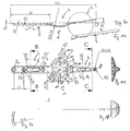
- a wrist arthrodesis plate 1 shown partially in sectional views. This can alternatively fix a left or a right wrist.
- the wrist arthrodesis plate is formed symmetrically to an imaginary longitudinal central axis.
- the wrist arthrodesis plate 1 is subdivided into three sections, namely, a left proximal fixation section 2 for fixing the wrist arthrodesis plate 1 at the radius, a middle carpal bone fixation section 3 for fixing the wrist arthrodesis plate 1 into at least two carpal bones and a distal fixation section 4 for fixing the wrist arthrodesis plate 1 on a metacarpal bone and / or on a phalanx bone.
- the fixing sections 2, 4 are formed as elongated metal sections of small width extension, wherein the width extension of the carpal bone fixing section 3 is greater than the longitudinal extent thereof.
- the fixing section 2 In order to allow an optimal investment of the proximal fixing section 2 at the radius, the fixing section 2, as is apparent from Fig. 1e results in curved transversely to its longitudinal extent on the underside executed.
- the proximal fixing section 2 In the proximal fixing section 2 there are three fixing holes 5a, 5b, 5c spaced apart from each other in the longitudinal extension of the wrist arthrodesis plate 1, each having an internal thread for respectively receiving a single bone screw.
- 1c is further, is located centrally between the middle fixing hole 5b and the right in the plane of the fixing hole 5c extending in the direction of the longitudinal extent of the proximal Fixierabiteses 2 slot 5 whose width, ie its extension transverse to the longitudinal extent of the proximal Fixierabroughes 2 in the direction of Carpal bone fixation section 3 decreases, from a radius R 2.4 to a radius R 1.93.
- Fig. 1a results in the fixed state upper, in the drawing plane bottom side of the wrist arthrodesis plate 1 wave-shaped, to a facilitated, defined bending the Wrist arthrodesis plate 1 to allow adaptation to the anatomical conditions.
- the width of the proximal fixation section 2 remains constant substantially over its longitudinal extent, the width of the distal fixation section 4 decreases towards its free end.
- a slot 7 In the distal fixing section 4 is a slot 7 with a constant width extension.
- a fixing hole 8 In the region of the free end of the distal fixing section 4 is a fixing hole 8 for receiving a bone screw.
- the upper fixation state of the distal fixation section 4 is also wave-shaped, wherein the wave amplitudes are flattened analogously to the proximal fixation section 2.
- Fig. 1a shows that the elongated distal fixing section is inclined at an angle ⁇ of 8 ° in this embodiment to the longitudinal extension of the proximal fixing section 2.
- the carpal bone fixing section 3 arranged centrally between the fixing sections 2, 4 is, as is apparent Fig. 1a results in a convex (convex) and extends in the direction away from the wrist, ie in the dorsal direction. From a synopsis of Fig. 1a, 1c and 1d shows that the carpal bone fixing section 3 is spoon-like curved and substantially in the plan view according to Fig. 1c is contoured oval.
- Fig. 1c and Fig. 1d results, at least five through holes 9 are provided, the centers 10 are spaced transversely to the longitudinal extent of the wrist arthrodesis plate. Likewise, at least five through holes 9 are provided, the centers 10 are spaced in the direction of the longitudinal extent of the wrist arthrodesis plate 1. Overall, the through holes 9 are arranged distributed such that in each of the total of seven carpal bones of the human hand each have a bone screw can be screwed. How to continue Fig. 1c results, at least three through holes 9 are arranged between two in the direction of the longitudinal extent of the wrist arthrodesis plate 1 spaced-through holes 9. There are also at least three further through-holes 9 between two maximum through holes spaced transversely to the longitudinal extent of the wrist arthrodesis plate 1.
- a wrist arthrodesis plate 1 for fixing a left wrist is shown.
- this wrist arthrodesis plate 1 is not arranged mirror-symmetrically to a longitudinal central axis. Rather, both the proximal fixing section 2 and the distal fixing section 4 are arranged laterally offset relative to an imaginary longitudinal central axis, wherein also in the exemplary embodiment according to FIG Fig. 2 the two fixing sections 2, 4 are aligned in the direction of the longitudinal extension of the wrist arthrodesis plate 1, including an angle.
- a wrist arthrodesis plate 1 designed to fix a right wrist is shown with a proximal, a distal and a carpal bony fixation section 2, 4, 3.
- wrist Arthrodesenplatten 1 according to the Fig. 2 to 3b is to recognize that the carpal bone fixing portion 3 in the direction away from the wrist curved, ie convex, is formed in the manner of a spoon.
- FIG. 4 to 5b alternative wrist arthrodesis plates 1 are shown which deliberately dispense with a distal fixation section, in contrast to the previously described embodiments.
- the wrist arthrodesis plates 1 according to Fig. 4 to 5b comprise exclusively a proximal fixing section 2 and an adjoining carpal bone fixing section 3, wherein the proximal fixing section 2 and the carpal bone fixing section 3 are substantially analogous to the embodiments according to FIGS Fig. 2 to 3b are formed.
- Fig. 4 shown embodiment with an in the plane of the drawing relative to an imaginary, centered by the carpal bone fixation section 3 extending longitudinal central axis offset proximal Fixierabites 2 is suitable for fixing a left wrist
- the in Fig. 5a and 5b As shown embodiment shows a wrist arthrodesis plate 1, which is suitable for fixing a right wrist.
- a wrist arthrodesis plate 1 which is designed for fixing a left wrist.
- the central carpal bone fixing portion 3 is formed flat so that the center axes of the plurality of through holes 9 are oriented parallel to each other.
- the proximal fixing section 2 are a total of three spaced-apart fixing holes 5a, 5b, 5c for receiving a respective fixing screw, wherein between the fixing holes 5b and 5c, a tapered slot 6 is arranged.
- the slot 7 does not taper in the distal fixing section 4.
- a fixing hole 8 is provided in the distal fixing section 4, whose internal thread has a smaller diameter than the internal thread of the fixing holes 5a, 5b, 5c.
- the distal fixing portion 4 is inclined to the proximal fixing portion 2 and to the carpal bone fixing flat portion 3 at an angle ⁇ of 8 °.
- FIG. 7a and 7b an embodiment of a wrist arthrodesis plate 1 is shown in which deliberately has been dispensed with the provision of a distal Fixierabroughes.
- the wrist arthrodesis plate 1 comprises a proximal fixing section 2, which is shaped analogously to the preceding embodiments.
- the planar, oval-shaped carpal bone fixing section 3 comprises a total of fourteen through-holes 9, wherein the through-holes 9 are arranged essentially in rows of four or five through-holes extending transversely to the longitudinal extent of the wrist arthrodesis plate 1.
- Fig. 8 is the embodiment according to Fig. 6a again shown without dimensions.
- the wrist arthrodesis plate 1 is used for fixing a left wrist and has for this purpose two, in the drawing plane down relative to an imaginary, centrally through the carpal bone fixation 3 extending, longitudinal central axis offset fixing 2, 4, between them the carpal bone fixation section 3, in the shown Embodiment just formed, record between them.
- a wrist arthrodesis plate 1 designed to fix a right wrist is shown.
- the proximal and the distal fixing section 2, 4 are arranged offset in the plane of the drawing upwards relative to an imaginary central longitudinal axis extending through the carpal bone fixing section 3.
- Fig. 9b is the flat version of the carpal fixation section 3 can be seen.
- Fig. 10 to 11b show embodiments of wrist arthrodesis plates 1 each without distal fixation section 4, only with proximal fixation section 2, wherein the slot 6 in the proximal fixation section 2 analogous to the Embodiments according to the Fig. 8 to 9b , in contrast to the embodiments 1 to 7b is not tapered.
- wrist arthrodesis plate 1 shown is suitable for fixing a left wrist
- wrist arthrodesis plate 1 is formed for fixing a right wrist.
- Fig. 11b is the flat shape of the carpal bone fixation section 3 can be seen.
- a wrist arthrodesis plate 1 with laterally offset, proximal and distal fixing section 2, 4 is shown.
- the carpal bone fixation section 3 is located above the carpal bones 11, which are located distally of the radius 12 (spoke) and the wrist 13, which in turn is formed between the radius 12 and the carpal bone 11.
- a bone screw 14 is to be received in the fixing holes 5a, 5b, 5c.
- a total of five bone screws 14 are provided for receiving in different through holes 9 in the carpal bone fixing section 3 in the illustrated embodiment.
- the distal fixation section 4 is fixed to the third metacarpal bone 15 in the fixation hole 8 with the aid of a single bone screw 14.
- a wrist arthrodesis plate 1 partially fixed to a left arm is shown. This does not include a distal fixing section and is fixed by means of two bone screws 14 at the radius 12.
- the carpal bone fixing section 3 can be fixed in more than three carpal bones 11 with a maximum of fourteen distributed bone screws 14.
- fixing possibilities of the proximal and distal fixation section 2, 4 it is possible to fix the proximal or distal fixation section 2, 4 by placing at least one bone screw in a slot 6, 7 at the radius 12 and the metacarpal bone 15.
- a fixation on the metacarpal bone 15 is according to the embodiment Fig. 13 deliberately not given and not necessary.
Abstract
Description
Die Erfindung betrifft eine Handgelenkarthrodeseplatte gemäß dem Oberbegriff des Anspruchs 1 sowie ein Sortiment, umfassend mindestens zwei unterschiedliche Handgelenkarthrodeseplatten gemäß Anspruch 13.The invention relates to a wrist arthrodesis plate according to the preamble of
Die Handgelenkarthrodese ist ein etabliertes chirurgisches Verfahren, das vorausschaubar Schmerzen lindert und ein stabiles Handgelenk für den Kraftgriff liefert. In der Praxis werden zur Versteifung des Handgelenks dorsale, langgestreckte Knochenplatten benutzt. Diese bieten die Möglichkeit, die Knochenplatte zum einen am Radius (Speiche) und zum anderen an einem Mittelhandknochen zu fixieren. Schraubverankerungen in den Handwurzelknochen sind über zwei, maximal drei Durchgangslöcher möglich, die in Richtung der Längserstreckung der Knochenplatte hintereinander angeordnet sind. Ferner von Nachteil bei bekannten Knochenplatten ist, dass diese, insbesondere im Bereich des Mittelhandknochens, relativ dick auftragen. Hier kann es zu Weichteilstörungen bzw. Wundheilstörungen kommen.Wrist arthrodesis is a well-established surgical procedure that predictably relieves pain and provides a stable wrist for the power grip. In practice, dorsal, elongated bone plates are used to stiffen the wrist. These offer the possibility to fix the bone plate on the one hand on the radius (spoke) and on the other hand on a metacarpal bone. Screw anchors in the carpal bones are possible via two, a maximum of three through holes, which are arranged one behind the other in the direction of the longitudinal extent of the bone plate. Another disadvantage of known bone plates is that they apply relatively thick, in particular in the area of the metacarpal bone. This can lead to soft tissue disorders or wound healing disorders.
Die
Die
Der Erfindung liegt die Aufgabe zugrunde, eine alternative Handgelenkarthrodeseplatte vorzuschlagen, die eine sichere Versteifung des Handgelenks ermöglicht. Dabei sollte die Handgelenkarthrodeseplatte dem Operateur möglichst viele Freiheiten bei seinem chirurgischen Eingriff im Hinblick auf die Verankerungsmöglichkeiten bieten. Ferner besteht die Aufgabe darin, ein Sortiment, umfassend mindestens zwei wie zuvor beschrieben ausgebildete Handgelenkarthrodeseplatten vorzuschlagen.The invention has for its object to propose an alternative wrist arthrodesis plate, the secure stiffening of the wrist allows. The wrist arthrodesis plate should offer the surgeon as much freedom as possible in his surgical procedure with regard to the anchoring possibilities. Furthermore, the object is to propose an assortment comprising at least two wrist arthrodesis plates designed as described above.
Diese Aufgabe wird mit einer Handgelenkarthrodeseplatte mit den Merkmalen des Anspruchs 1 und hinsichtlich des Sortiments mit den Merkmalen des Anspruchs 13 gelöst. Vorteilhafte Weiterbildungen der Erfindung sind in den Unteransprüchen angegeben. In den Rahmen der Erfindung fallen sämtliche Kombinationen aus zumindest zwei von in der Beschreibung, den Ansprüchen und/oder den Figuren offenbarten Merkmalen.This object is achieved with a wrist arthrodesis plate with the features of
Der Erfindung liegt der Gedanke zugrunde, den Handwurzelknochenfixierabschnitt derart zu verbreitern, dass die Mittelpunkte mindestens zweier Durchgangslöcher zur Aufnahme jeweils mindestens einer Knochenschraube quer zur Längserstreckung der Handgelenkarthrodeseplatte beabstandet sind, derart, dass in mindestens zwei quer zur Längserstreckung der Handgelenkarthrodeseplatte, abschnittsweise oder vollständig, nebeneinander angeordnete Handwurzelknochen jeweils mindestens eine Knochenschraube einschraubbar ist. Anders ausgedrückt zeichnet sich eine nach dem Konzept der Erfindung ausgebildete Handgelenkarthrodeseplatte durch mindestens zwei, vorzugsweise mehr als zwei, quer zur Längserstreckung der Handgelenkarthrodeseplatte und ggf. auch in Richtung der Längserstreckung, zumindest abschnittsweise, versetzt angeordnete, vorzugsweise quer zur Längserstreckung der Handgelenkarthrodeseplatte sowie ggf. auch in Richtung der Längserstreckung voneinander beabstandete, Durchgangslöcher aus, die zur Aufnahme jeweils mindestens einer, vorzugsweise zur Aufnahme jeweils maximal einer, Knochenschraube ausgebildet sind, mit dem Ziel, eine Möglichkeit zu schaffen, die Handgelenkarthrodeseplatte, genauer den Handwurzelknochenfixierabschnitt, an mindestens zwei quer zur Längserstreckung, abschnittsweise oder vollständig, nebeneinander angeordneten Handwurzelknochen zu fixieren. Noch Anders ausgedrückt, sind die Durchgangslöcher derart angeordnet, dass oberhalb mindestens zweier, zumindest abschnittsweise, vorzugsweise vollständig, nebeneinander angeordneter Handwurzelknochen sich jeweils ein Durchgangsloch befindet. Noch anders ausgedrückt ist vorgesehen, dass die Durchgangslöcher im Handwurzelknochenfixierabschnitt derart quer zur Längserstreckung des Handgelenkarthrodeseplatte (1) beabstandet angeordnet sind, dass in mindestens zwei quer zur Längserstreckung der Handgelenkarthrodeseplatte, zumindest abschnittsweise, vorzugsweise vollständig, nebeneinander angeordnete Handwurzelknochen jeweils mindestens eine Knochenschraube einschraubbar ist. Ganz besonders bevorzugt umfasst der Handwurzelknochenfixierabschnitt eine Vielzahl von Durchgangslöchern, von denen mindestens zwei um mindestens einen Durchgangslochdurchmesser quer zur Längserstreckung der Handgelenksarthrodeseplatte betrachtet voneinander beabstandet sind. Ganz besonders bevorzugt ist eine Ausführungsform, bei der Knochenschrauben durch eine entsprechende seitliche Beabstandung der Mittelpunkte zweier Durchgangslöcher in mindestens zwei über mindestens einen Handwurzelknochen voneinander beabstandete Handwurzelknochen schraubbar sind. Um Weichteilstörungen und/oder Wundheilstörungen im Bereich der Mittelhandknochen (Ossametacarpalia) zu vermeiden, ist es besonders bevorzugt, wenn die, insbesondere aus einer Titanlegierung ausgebildete, Handgelenkarthrodeseplatte eine maximale Materialstärke von 3 mm, vorzugsweise von etwa 2,5mm oder darunter aufweist. Insgesamt zeichnet sich eine nach dem Konzept der Erfindung ausgebildete Handgelenkarthrodeseplatte durch die Möglichkeit einer Mehrfachverankerung im Bereich der Handwurzelknochen aus, mit der Folge, dass eine im Stand der Technik problematische Verankerung der Handgelenkarthrodeseplatte im dritten Mittelhandknochen besser unterstützt wird oder sogar, wie später noch erläutert werden wird, ganz entfallen kann. Bevorzugt ist der distale Fixierabschnitt zur Fixierung der Handgelenkarthrodeseplatte am Radius (Speiche) im Vergleich zum Stand der Technik verlängert, wodurch die Flexibilität in der Anwendung weiter erhöht wird. Insbesondere kann im Falle einer entsprechenden unterarmseitigen Verlängerung der Handgelenkarthrodeseplatte, in Abhängigkeit davon, wie viel Knochensubstanz im Bereich des Handgelenks oder der Handwurzelknochen noch zur Verfügung steht, die Handgelenkarthrodeseplatte flexibel angepasst werden.The invention is based on the idea of widening the carpal bone fixing section in such a way that the centers of at least one bone screw are spaced transversely to the longitudinal extent of the wrist arthrodesis plate such that in at least two transversely to the longitudinal extent of the wrist arthrodesis plate, in sections or completely, side by side arranged carpal bones in each case at least one bone screw can be screwed. In other words, a wrist arthrodesis plate formed according to the concept of the invention is characterized by at least two, preferably more than two, transversely to the longitudinal extent of the wrist arthrodesis plate and possibly also in the direction of the longitudinal extension, at least partially offset, preferably transversely to the longitudinal extent of the wrist arthrodesis plate and optionally Also in the direction of the longitudinal extension spaced from each other, through holes, which are each designed to accommodate at least one, preferably for receiving each a maximum of bone screw, with the aim to create a possibility, the wrist arthrodesis plate, more precisely the carpal bone fixation, at least two transverse to Longitudinal extension, in sections or completely, to fix adjacent carpal bones. In other words, the through-holes are arranged such that above at least two, at least in sections, preferably completely, side by side arranged carpal bones each have a through hole. In other words, it is provided that the through holes in the carpal bone fixing section are arranged transversely to the longitudinal extension of the wrist arthrodesis plate (1), that in at least two transverse to the longitudinal extension of the wrist arthrodesis, at least partially, preferably completely, juxtaposed carpal bones at least one bone screw can be screwed. Most preferably, the carpal bone fixing portion comprises a plurality of through holes, at least two of which are spaced apart by at least one through hole diameter viewed transversely to the longitudinal extent of the wrist arthrodesis plate. Especially preferred is an embodiment in which bone screws can be screwed by a corresponding lateral spacing of the centers of two through holes in at least two carpal bones spaced apart from each other by at least one carpal bone. In order to avoid soft-tissue disorders and / or wound healing disorders in the metacarpals (ossametacarpalia), it is particularly preferred if the wrist arthrodesis plate, in particular made of a titanium alloy, has a maximum material thickness of 3 mm, preferably about 2.5 mm or less. Overall, a trained according to the concept of the invention wrist arthrodesis is characterized by the possibility of multiple anchoring in the carpal bones, with the result that a problematic in the prior art anchoring the wrist arthrodesis in the third metacarpal bone is better supported or even, as will be explained later will be completely eliminated. Preferably, the distal fixation section for fixing the wrist arthrodesis plate to the radius (spoke) is extended in comparison to the prior art, whereby the flexibility in the application is further increased. In particular, in the case of a corresponding forearm-side extension of the wrist arthrodesis plate, depending on how much bone substance in the area Wrist or the carpal bones is still available, the wrist arthrodesis plate can be flexibly adjusted.
In Weiterbildung der Erfindung ist mit Vorteil vorgesehen, dass die Durchgangslöcher im Handwurzelknochenfixierabschnitt derart verteilt angeordnet und in einer Anzahl vorgesehen sind, dass eine Fixierung der Handgelenkarthrodeseplatte bzw. des Handwurzelknochenfixierabschnitts in mindestens drei Handgelenkwurzelknochen mit jeweils mindestens einer Knochenschraube möglich ist. Auf diese Weise kann der Operateur auswählen, in welchem/welchen Handwurzelknochen eine Fixierung realisiert werden soll.In a further development of the invention is advantageously provided that the through holes in the carpal bone fixation arranged distributed and provided in a number that a fixation of the wrist arthrodesis or the carpal bone fixation in at least three wrist root bone, each with at least one bone screw is possible. In this way, the surgeon can select in which / which carpal bones a fixation should be realized.
Besonders zweckmäßig ist eine Ausführungsform der Handgelenkarthrodeseplatte, bei der diese eine Vielzahl, d.h. mehr als drei, von Durchgangslöchern im Handwurzelfixierabschnitt aufweist. Dabei ist es besonders bevorzugt, wenn die Mittelpunkte von mindestens drei, vorzugsweise von mindestens vier, ganz besonders bevorzugt von fünf Durchgangslöchern quer zur Längserstreckung der Handgelenkarthrodeseplatte voneinander beabstandet sind. Zusätzlich oder alternativ ist es von Vorteil, wenn die Mittelpunkte von mindestens zwei, vorzugsweise von mindestens drei, ganz besonders bevorzugt von mindestens vier oder fünf Durchgangslöchern in Richtung der Längserstreckung der Handgelenksarthrodeseplatte voneinander beabstandet sind. Besonders bevorzugt wird eine flächige Matrix von Durchgangslöchern erhalten, die eine Fixierung der Handgelenkarthrodeseplatte an sämtlichen Handwurzelknochen ermöglicht.Particularly useful is an embodiment of the wrist arthrodesis plate in which these have a plurality, i. more than three, of through-holes in the carpal fixation section. It is particularly preferred if the centers of at least three, preferably at least four, most preferably of five through holes are spaced transversely to the longitudinal extension of the wrist arthrodesis plate. Additionally or alternatively, it is advantageous if the centers of at least two, preferably of at least three, most preferably of at least four or five through holes in the direction of the longitudinal extent of the wrist arthrodesis plate are spaced from each other. Particularly preferred is a flat matrix of through holes is obtained, which allows a fixation of the wrist arthrodesis plate on all carpal bones.
Eine maximale Flexibilität für den Operateur wird erhalten, wenn im Handwurzelfixierabschnitt mindestens fünf voneinander beabstandete Durchgangslöcher vorgesehen sind. Besonders bevorzugt ist es, wenn mindestens acht, ganz besonders bevorzugt mindestens zehn oder mindestens dreizehn Durchgangslöcher im Handwurzelfixierabschnitt vorgesehen sind. Eine optimale Flexibilität für den Operateur wird erhalten, wenn der Handwurzelknochenfixierabschnitt der Handgelenkarthrodeseplatte vierzehn oder mehr Durchgangslöcher umfasst.Maximum flexibility for the surgeon is obtained if at least five spaced through holes are provided in the carpal fixation section. It is particularly preferred if at least eight, more preferably at least ten or at least thirteen through-holes are provided in the carcass fixation section. Optimal flexibility for the surgeon is obtained when the carpal bone fixation portion of the wrist arthrodesis plate includes fourteen or more through holes.
Um das Handgelenk in einer, zumindest weitgehend, natürlichen Entspannungsposition fixieren zu können, ist eine Ausführungsform von Vorteil, bei der der Handwurzelknochenfixierabschnitt ballig ausgeformt ist, sich also dorsal erhebt. Bevorzugt weist der Handwurzelknochenfixierabschnitt dabei, zumindest näherungsweise, eine Löffelform auf, um den anatomischen Gegebenheiten in möglichst vielen Fällen gerecht zu werden. Alternativ ist eine Ausführungsform realisierbar, bei der der Handwurzelknochenfixierabschnitt eben ausgeformt ist und bevorzugt, zumindest näherungsweise, in einer gemeinsamen Ebene mit dem distalen Fixierabschnitt liegt.In order to be able to fix the wrist in a, at least largely, natural relaxation position, an embodiment in which the carpal bone fixing section is formed spherically, that is, rises dorsally, is advantageous. The carpal bone fixing section preferably has, at least approximately, a spoon shape in order to meet the anatomical conditions in as many cases as possible. Alternatively, an embodiment can be realized in which the carpal bone fixing section is formed flat and preferably, at least approximately, lies in a common plane with the distal fixing section.
Besonders bevorzugt ist eine Ausführungsform der Handgelenkarthrodeseplatte, bei der der Handwurzelknochenfixierabschnitt sich in Bezug auf die Längserstreckung des proximalen Fixierabschnitts in zwei einander entgegengesetzte Querrichtungen erstreckt, wobei es weiter bevorzugt ist, wenn auf beiden sich in jeweils eine Querrichtung erstreckenden, also nicht mit dem proximalen Fixierabschnitt fluchtenden Flächenabschnitten des Handwurzelknochenfixierabschnitts jeweils mindestens eine, vorzugsweise jeweils mehrere Durchgangsöffnungen zur Aufnahme jeweils mindestens einer, vorzugsweise zur Aufnahme jeweils ausschließlich einer, Knochenschraube vorgesehen sind.Particularly preferred is an embodiment of the wrist arthrodesis plate in which the carpal bone fixation section extends in two opposite transverse directions with respect to the longitudinal extension of the proximal fixation section, wherein it is further preferred if both extend in a respective transverse direction, ie not with the proximal fixation section at least one, preferably in each case a plurality of through openings for receiving in each case at least one, preferably for receiving in each case only one, bone screw are provided in aligned surface portions of the carpal bone fixation section.
In Weiterbildung der Erfindung ist mit Vorteil vorgesehen, dass mindestens eine der Durchgangsöffnungen im Handwurzelknochenfixierabschnitt, vorzugsweise mehrere der im Handwurzelknochenfixierabschnitt angeordnete Durchgangsöffnungen, ganz besonders bevorzugt sämtliche Durchgangsöffnungen im Handwurzelknochenfixierabschnitt mit einem Innengewinde ausgestattet sind, das zur fixierenden Aufnahme einer Knochenschraube dient.In a further development of the invention it is advantageously provided that at least one of the passage openings in the carpal bone fixing section, preferably a plurality of through openings arranged in the carpal bone fixing section, very particularly preferably all through openings in the carpal bone fixing section, are provided with an internal thread which serves to fix a bone screw.
Besonders zweckmäßig ist es, wenn zur weiteren Erhöhung der Handhabungsflexibilität durch den Operateur im proximalen Fixierabschnitt zum Fixieren der Handgelenkarthrodeseplatte am Radius mindestens ein Langloch vorgesehen ist, das sich ganz besonders bevorzugt in Richtung der Längserstreckung der Handgelenkarthrodeseplatte erstreckt. Besonders bevorzugt ist es dabei, wenn sich das Langloch in Richtung auf den Handwurzelknochenfixierabschnitt zu verjüngt, wodurch der Einsatz unterschiedlich großer Knochenschrauben ermöglicht wird.It is particularly expedient if, to further increase the handling flexibility by the surgeon in the proximal fixing section for fixing the wrist arthrodesis plate at least one elongated hole is provided on the radius, which is very particularly preferably in the direction of Longitudinal extension of the wrist arthrodesis plate extends. It is particularly preferred when the slot tapers in the direction of the carpal bone fixing section, whereby the use of different sized bone screws is made possible.
In Weiterbildung der Erfindung ist mit Vorteil vorgesehen, dass zusätzlich zu dem proximalen Fixierabschnitt ein sich distal von dem Handwurzelknochenfixierabschnitt weg erstreckender distaler Fixierabschnitt zum Fixieren der Handgelenkarthrodeseplatte an einem Mittelhandknochen und/oder an einem Fingerglied, insbesondere am ersten Fingerglied (phalanx proximalis) vorgesehen ist. Um auch hierbei eine maximale Flexibilität für den Operateur zu bieten, ist es bevorzugt, wenn im distalen Fixierabschnitt mindestens ein sich, insbesondere in Richtung der Längserstreckung des distalen Fixierabschnittes erstreckendes Langloch vorgesehen ist.In a development of the invention, it is advantageously provided that, in addition to the proximal fixing section, a distal fixing section extending distally from the carpal bone fixing section is provided for fixing the wrist arthrodesis plate to a metacarpal bone and / or to a phalanx, in particular to the first phalanx proximalis. In order to provide maximum flexibility for the surgeon also in this case, it is preferred if at least one oblong hole is provided in the distal fixation section, in particular extending in the direction of the longitudinal extension of the distal fixation section.
Um eine möglichst natürliche Fixierstellung zu realisieren, ist es besonders bevorzugt, wenn der distale Fixierabschnitt zum proximalen Fixierabschnitt unter einem Winkel geneigt ist. Bevorzugt beträgt der Neigungswinkel mindestens 5°, ganz besonders bevorzugt etwa 8°.In order to realize the most natural possible fixing position, it is particularly preferred if the distal fixing section is inclined at an angle to the proximal fixing section. Preferably, the angle of inclination is at least 5 °, most preferably about 8 °.
Idealerweise ist die Handgelenkarthrodeseplatte im Bereich ihres Handwurzelknochenfixierabschnitts verbiegbar, sodass der gewünschte Winkel auf einfache Weise einstellbar ist.Ideally, the wrist arthrodesis plate is bendable in the area of its carpal bone fixation section so that the desired angle is easily adjustable.
Aufgrund des im Vergleich zum Stand der Technik verbreiterten Handgelenkwurzelknochenfixierabschnittes ist auch eine Ausführungsform der Handgelenkarthrodeseplatte realisierbar, bei der bewusst auf das Vorsehen eines distalen Fixierabschnitts verzichtet wird, wodurch Entzündungsreaktionen im Bereich der Mittelhandknochen vollständig vermieden werden können.Due to the widened wrist wrist bone fixation section, which is widened in comparison with the prior art, an embodiment of the wrist arthrodesis plate can be realized in which the provision of a distal fixation section is consciously dispensed with, whereby inflammatory reactions in the area of the metacarpal bones can be completely avoided.
Die Erfindung führt auch auf ein Sortiment, umfassend mindestens zwei wie zuvor beschriebene Handgelenkarthrodeseplatten, die sich in mindestens einem Formmerkmal unterscheiden. Dabei ist eine Ausführungsform des Sortiments besonders bevorzugt, bei der dieses mindestens eine Handgelenkarthrodeseplatte mit einem distalen Fixierabschnitt und mindestens eine Handgelenkarthrodeseplatte ohne distalen Fixierabschnitt aufweist.The invention also leads to an assortment comprising at least two wrist arthrodesis plates as described above which differ in at least one shape feature. It is an embodiment of the Especially preferred range in which this has at least one wrist arthrodesis plate with a distal fixation and at least one wrist arthrodesis plate without distal fixation.
Besonders bevorzugt ist eine Ausführungsform des Sortiments, bei der die distalen und/oder proximalen Fixierabschnitte zweier Handgelenkarthrodeseplatten des Sortiments seitlich relativ zueinander versetzt angeordnet sind, um eine Fixierung an unterschiedlichen Querpositionen des Radius bzw. an eine Fixierung an unterschiedlichen Mittelhandknochen zu ermöglichen.Particularly preferred is an embodiment of the assortment in which the distal and / or proximal fixing sections of two wrist arthrodesis plates of the assortment are laterally offset relative to one another in order to enable fixation at different transverse positions of the radius or at a fixation on different metacarpal bones.
Weitere Vorteile, Merkmale und Einzelheiten der Erfindung ergeben sich aus der nachfolgenden Beschreibung bevorzugter Ausführungsbeispiele sowie anhand der Zeichnungen. In diesen sind Abmessungen von bevorzugten Ausführungsformen angegeben. Die Abmessungen sowie sich aus diesen ergebende Abmessungsverhältnisse sollen als erfindungswesentlich offenbart gelten und beanspruchbar sein. Die Abmessungen und Abmessungsverhältnisse in den Zeichnungen sollen den Schutzumfang der in den Ansprüchen zum Ausdruck kommenden Erfindung jedoch nicht einschränken.Further advantages, features and details of the invention will become apparent from the following description of preferred embodiments and from the drawings. In these dimensions of preferred embodiments are given. The dimensions and resulting from these dimensional ratios should be considered essential to the invention disclosed and claimable. However, the dimensions and dimensional relationships in the drawings are not intended to limit the scope of the invention as expressed in the claims.
Es zeigen:
- Fig. 1a bis 1f
- unterschiedliche Ansichten und Schnittdarstellungen eines ersten Ausführungsbeispiels der dorsalen Handgelenkarthrodeseplatte,
- Fig. 2
- eine alternative Ausführungsform einer Handgelenkarthrodeseplatte zur Fixierung des linken Handgelenks,
- Fig. 3a und 3b
- unterschiedliche Ansichten einer Ausführungsform einer Handgelenkarthrodeseplatte zur Fixierung eines rechten Handgelenks,
- Fig.4
- eine Ausführungsform einer Handgelenkarthrodeseplatte ohne distalen Fixierabschnitt zum Fixieren eines linken Handgelenks,
- Fig. 5a und 5b
- unterschiedliche Ansichten einer Handgelenkarthrodeseplatte ohne distalen Fixierabschnitt zur Fixierung eines rechten Handgelenks,
- Fig. 6a bis 6c
- unterschiedliche, teilweise geschnittene Ansichten einer Ausführungsform einer Handgelenkarthrodeseplatte mit flachem Handwurzelknochenfixierabschnitt
- Fig. 7a und 7b
- eine alternative Ausführungsform einer Handgelenkarthrodeseplatte mit flachem Handwurzelknochenfixierabschnitt, jedoch ohne distalen Fixierabschnitt,
- Fig.8
- eine Ausführungsform einer Handgelenkarthrodeseplatte mit flachem (ebenem) Handwurzelknochenfixierabschnitt sowie mit einem distalen Fixierabschnitt zur Fixierung eines linken Handgelenks,
- Fig. 9a und 9b
- eine Ausführungsform einer Handgelenkarthrodeseplatte zur Fixierung eines rechten Handgelenks,
- Fig. 10
- eine Ausführungsform einer Handgelenkarthrodeseplatte mit ebenem Handwurzelknochenfixierabschnitt, jedoch ohne distalen Fixierabschnitt zur Fixierung eines linken Handgelenks,
- Fig. 11a und 11b
- unterschiedliche Ansichten einer Handgelenkarthrodeseplatte ohne distalen Fixierabschnitt zur Fixierung eines rechten Handgelenks,
- Fig. 12
- die in den
Fig. 6a bis 6b gezeigte Arthrodeseplatte, teilweise fixiert an einem linken Handgelenk, und - Fig. 13
- die in den
Fig. 7a und 7b gezeigte Handgelenkarthrodeseplatte, teilweise fixiert an einem linken Handgelenk.
- Fig. 1a to 1f
- different views and sectional views of a first embodiment of the dorsal wrist arthrodesis plate,
- Fig. 2
- an alternative embodiment of a wrist arthrodesis plate for fixing the left wrist,
- Fig. 3a and 3b
- different views of an embodiment of a wrist arthrodesis plate for fixing a right wrist,
- Figure 4
- an embodiment of a wrist arthrodesis plate without a distal fixing section for fixing a left wrist,
- Fig. 5a and 5b
- different views of a wrist arthrodesis plate without a distal fixation section for fixing a right wrist,
- Fig. 6a to 6c
- different, partially sectioned views of an embodiment of a wrist arthrodesis plate with a flat carpal bone fixation
- Fig. 7a and 7b
- an alternative embodiment of a wrist arthrodesis plate with a flat carpal bone fixation section, but without a distal fixation section,
- Figure 8
- an embodiment of a wrist arthrodesis plate with a flat (flat) carpal bone fixation section and with a distal fixation section for fixing a left wrist,
- Fig. 9a and 9b
- an embodiment of a wrist arthrodesis plate for fixing a right wrist,
- Fig. 10
- an embodiment of a wrist arthrodesis plate with a flat carpal bony fixation section, but without a distal fixation section for fixing a left wrist,
- Fig. 11a and 11b
- different views of a wrist arthrodesis plate without a distal fixation section for fixing a right wrist,
- Fig. 12
- in the
Fig. 6a to 6b shown arthrodesis plate, partially fixed to a left wrist, and - Fig. 13
- in the
Fig. 7a and 7b wrist arthrodesis plate shown partially fixed to a left wrist.
In den Figuren sind gleiche Elemente und Elemente mit der gleichen Funktion mit den gleichen Bezugszeichen gekennzeichnet.In the figures, like elements and elements having the same function are denoted by the same reference numerals.
In den
Um eine optimale Anlage des proximalen Fixierabschnittes 2 am Radius zu ermöglichen, ist der Fixierabschnitt 2, wie sich aus
Wie sich insbesondere aus
Während die Breitenerstreckung des proximalen Fixierabschnittes 2 im Wesentlichen über seine Längserstreckung konstant bleibt, nimmt die Breitenerstreckung des distalen Fixierabschnittes 4 hin zu dessen freien Ende ab. Im distalen Fixierabschnitt 4 befindet sich ein Langloch 7 mit konstanter Breitenerstreckung. Im Bereich des freien Endes des distalen Fixierabschnittes 4 befindet sich ein Fixierloch 8 zur Aufnahme einer Knochenschraube.While the width of the
Wie sich aus der Detailvergrößerung gemäß
Aus
Der mittig zwischen den Fixierabschnitten 2, 4 angeordnete Handwurzelknochenfixierabschnitt 3 ist, wie sich aus
In der Flächenerstreckung des Handwurzelknochenfixierabschnittes 3 sind eine Vielzahl, hier achtzehn, Durchgangslöcher 9 eingebracht, die jeweils die Aufnahme einer Knochenschraube ermöglichen. Zu erkennen ist, dass die Mittelachsen der Durchgangslöcher 9 je nach Relativposition zueinander geneigt sind. Dies ist darauf zurückzuführen, dass die Durchgangslöcher 9 sich im Wesentlichen senkrecht zur in Längsrichtung gekrümmten Oberfläche des Handwurzelknochenfixierabschnittes 3 erstrecken.In the surface extension of the carpal
Wie sich aus
In
In den
In den
In den
Wie sich aus den
In
In
In den
In
In
Claims (14)
dadurch gekennzeichnet,
dass zumindest eines der Durchgangslöcher (9) im Handwurzelknochenfixierabschnitt (3) ein Innengewinde aufweist.A wrist arthrodesis plate comprising a proximal fixation section (2) for fixing the wrist arthrodesis plate (1) to the radius (12) and a carpal bony fixation section (3) for holding at least one bone screw (14) for fixing the wrist arthrodesis plate (1 ) on carpal bones (11), wherein the through holes (9) in the carpal bone fixing section (3) are arranged such that above at least two carpal bones each one of the through holes (8) is located,
characterized,
in that at least one of the through holes (9) in the carpal bone fixing section (3) has an internal thread.
dass im Handwurzel-knochenfixierabschnitt (3) die Mittelpunkte (10) von mindestens drei, vorzugsweise von mindestens vier, Durchgangslöchern (9) quer zur Längserstreckung der Handgelenkarthrodeseplatte (1) nebeneinander und/oder die Mittelpunkte (10) von mindestens zwei, vorzugsweise von mindestens drei, bevorzugt von mindestens vier, Durchgangslöchern (9) in Richtung der Längserstreckung der Handgelenkarthrodeseplatte (1) hintereinander angeordnet sind.Wrist arthrodesis plate according to one of the preceding claims, characterized
that the center points (10) of at least three, preferably at least four, passage holes (9) transverse to the longitudinal extension of the Handgelenkarthrodeseplatte (1) side by side in the carpal knochenfixierabschnitt (3) and / or the mid-points (10) of at least two, preferably at least three, preferably of at least four, through holes (9) in the direction of the longitudinal extent of the wrist arthrodesis plate (1) are arranged one behind the other.
dass mindestens fünf, vorzugsweise mindestens acht, bevorzugt mindestens zehn, besonders bevorzugt mindestens zwölf, ganz besonders bevorzugt mindestens dreizehn Durchgangslöcher (9) im Handwurzelknochenfixierabschnitt (3) vorgesehen sind.Wrist arthrodesis plate according to one of the preceding claims, characterized
in that at least five, preferably at least eight, preferably at least ten, particularly preferably at least twelve, very particularly preferably at least thirteen through-holes (9) are provided in the carpal bone fixing section (3).
dass der Handwurzelknochenfixierabschnitt (3) ballig, vorzugsweise löffelförmig, oder eben ausgeformt ist.Wrist arthrodesis plate according to one of the preceding claims, characterized
in that the carpal bone fixing section (3) is convex, preferably spoon-shaped or flat.
dass mehrere, insbesondere sämtliche Durchgangslöcher (9) im Handwurzelknochenfixierabschnitt (3) ein Innengewinde aufweisen.Wrist arthrodesis plate according to one of the preceding claims, characterized
in that several, in particular all through-holes (9) in the carpal bone fixing section (3) have an internal thread.
dass der Handwurzelknochenfixierabschnitt (3) den proximalen Fixierabschnitt (2) quer zu dessen Längserstreckung zweiseitig überragt.Wrist arthrodesis plate according to one of the preceding claims, characterized
that the Handwurzelknochenfixierabschnitt (3) to its longitudinal extension extends beyond the proximal fixing portion (2) across two sides.
dass in dem proximalen Fixierabschnitt (2) mindestens ein, vorzugsweise sich in Richtung des Handwurzelknochenfixierabschnitts (3) verjüngendes, Langloch (6) vorgesehen ist.Wrist arthrodesis plate according to one of the preceding claims, characterized
in that at least one oblong hole (6), preferably tapering in the direction of the carpal bone fixing section (3), is provided in the proximal fixing section (2).
dass ein, sich vorzugsweise in eine distale Richtung verjüngter, distaler Fixierabschnitt (4) zum Fixieren der Handgelenkarthrodeseplatte (1) an einem Mittelhandknochen (15) und/oder an einem Fingerglied vorgesehen ist.Wrist arthrodesis plate according to one of the preceding claims, characterized
in that a distal fixing section (4), which is preferably tapered in a distal direction, for fixing the wrist arthrodesis plate (1) a metacarpal bone (15) and / or on a finger member is provided.
dadurch gekennzeichnet,
dass der distale Fixierabschnitt (4) zum proximalen Fixierabschnitt (2) unter einem Winkel (?), vorzugsweise von mehr als 5°, geneigt ist.Wrist arthrodesis plate according to one of claims 9 or 10,
characterized,
in that the distal fixing section (4) is inclined to the proximal fixing section (2) at an angle ()), preferably greater than 5 °.
dadurch gekennzeichnet,
dass die Handgelenkarthrodeseplatte (1) keinen an den Handwurzelknochenfixierabschnitt (3) angrenzenden, distalen Fixierabschnitt (4) aufweist.Wrist arthrodesis plate according to one of claims 1 to 8,
characterized,
in that the wrist arthrodesis plate (1) has no distal fixing section (4) adjacent to the carpal bone fixing section (3).
dass mindestens eine der Handgelenkarthrodeseplatten (1) keinen distalen Fixierabschnitt (4) aufweist.Assortment according to claim 13, characterized
that at least one of the Handgelenkarthrodeseplatten (1) no distal fixing portion (4).
Applications Claiming Priority (1)
| Application Number | Priority Date | Filing Date | Title |
|---|---|---|---|
| DE200810039693 DE102008039693A1 (en) | 2008-08-26 | 2008-08-26 | Wrist arthrodesis plate and assortment |
Publications (2)
| Publication Number | Publication Date |
|---|---|
| EP2158864A2 true EP2158864A2 (en) | 2010-03-03 |
| EP2158864A3 EP2158864A3 (en) | 2010-04-21 |
Family
ID=41343139
Family Applications (1)
| Application Number | Title | Priority Date | Filing Date |
|---|---|---|---|
| EP09010717A Withdrawn EP2158864A3 (en) | 2008-08-26 | 2009-08-20 | Wrist arthrodesis board and range |
Country Status (2)
| Country | Link |
|---|---|
| EP (1) | EP2158864A3 (en) |
| DE (1) | DE102008039693A1 (en) |
Cited By (7)
| Publication number | Priority date | Publication date | Assignee | Title |
|---|---|---|---|---|
| WO2013045713A1 (en) * | 2011-09-26 | 2013-04-04 | Servicio Andaluz De Salud | Partial carpal arthrodesis device |
| EP2606843A1 (en) * | 2011-12-22 | 2013-06-26 | Stryker Trauma SA | Wrist fusion plate |
| US20150313654A1 (en) * | 2011-09-06 | 2015-11-05 | DePuy Synthes Products, Inc. | Pancarpal Arthrodesis Bone Plate |
| WO2018188861A1 (en) * | 2017-04-11 | 2018-10-18 | Waldemar Link Gmbh & Co. Kg | Arthrodesis plate |
| CN109171931A (en) * | 2018-10-10 | 2019-01-11 | 大泗医疗生物科技有限公司 | Merge lockplate and wrist fusion structure |
| EP3530224A1 (en) * | 2018-02-23 | 2019-08-28 | Medartis Holding AG | Wrist arthrodesis plate |
| RU2806997C1 (en) * | 2023-05-02 | 2023-11-08 | Федеральное государственное бюджетное учреждение "Национальный медицинский исследовательский центр травматологии и ортопедии имени Р.Р. Вредена" Министерства здравоохранения Российской Федерации | Internal fixator for shoulder arthrodesis |
Families Citing this family (1)
| Publication number | Priority date | Publication date | Assignee | Title |
|---|---|---|---|---|
| EP3777735A1 (en) | 2019-08-16 | 2021-02-17 | Medartis Holding AG | Plate for temporary bridging of fragments of a fracture |
Citations (2)
| Publication number | Priority date | Publication date | Assignee | Title |
|---|---|---|---|---|
| US5853413A (en) | 1997-04-18 | 1998-12-29 | Bristol-Myers Squibb Company | Wrist fusion plate |
| US6358250B1 (en) | 2000-02-01 | 2002-03-19 | Hand Innovations, Inc. | Volar fixation system |
Family Cites Families (2)
| Publication number | Priority date | Publication date | Assignee | Title |
|---|---|---|---|---|
| US6221073B1 (en) * | 1999-08-20 | 2001-04-24 | Kinetikos Medical, Inc. | Wrist fusion apparatus and method |
| WO2004045455A2 (en) * | 2002-11-19 | 2004-06-03 | Acumed Llc | Deformable bone plates |
-
2008
- 2008-08-26 DE DE200810039693 patent/DE102008039693A1/en not_active Withdrawn
-
2009
- 2009-08-20 EP EP09010717A patent/EP2158864A3/en not_active Withdrawn
Patent Citations (2)
| Publication number | Priority date | Publication date | Assignee | Title |
|---|---|---|---|---|
| US5853413A (en) | 1997-04-18 | 1998-12-29 | Bristol-Myers Squibb Company | Wrist fusion plate |
| US6358250B1 (en) | 2000-02-01 | 2002-03-19 | Hand Innovations, Inc. | Volar fixation system |
Cited By (14)
| Publication number | Priority date | Publication date | Assignee | Title |
|---|---|---|---|---|
| US20150313654A1 (en) * | 2011-09-06 | 2015-11-05 | DePuy Synthes Products, Inc. | Pancarpal Arthrodesis Bone Plate |
| US9743966B2 (en) * | 2011-09-06 | 2017-08-29 | DePuy Synthes Products, Inc. | Pancarpal arthrodesis bone plate |
| WO2013045713A1 (en) * | 2011-09-26 | 2013-04-04 | Servicio Andaluz De Salud | Partial carpal arthrodesis device |
| EP2606843A1 (en) * | 2011-12-22 | 2013-06-26 | Stryker Trauma SA | Wrist fusion plate |
| US9320554B2 (en) | 2011-12-22 | 2016-04-26 | Stryker European Holdings I, Llc | Wrist fusion plate |
| CN110475527A (en) * | 2017-04-11 | 2019-11-19 | 沃尔德马连接两合公司 | Arthrodesis plate |
| WO2018188861A1 (en) * | 2017-04-11 | 2018-10-18 | Waldemar Link Gmbh & Co. Kg | Arthrodesis plate |
| US11266450B2 (en) | 2017-04-11 | 2022-03-08 | Waldemar Link Gmbh & Co. Kg | Arthrodesis plate |
| EP3530224A1 (en) * | 2018-02-23 | 2019-08-28 | Medartis Holding AG | Wrist arthrodesis plate |
| WO2019162091A1 (en) * | 2018-02-23 | 2019-08-29 | Medartis Holding Ag | Wrist arthrodesis plate and method using a wrist arthrodesis plate |
| JP2021514720A (en) * | 2018-02-23 | 2021-06-17 | メダルティス・ホールディング・アクチェンゲゼルシャフトMedartis Holding Ag | Method using wrist joint fixation plate and wrist joint fixation plate |
| US11660130B2 (en) * | 2018-02-23 | 2023-05-30 | Medartis Holding Ag | Wrist arthrodesis plate and method using a wrist arthrodesis plate |
| CN109171931A (en) * | 2018-10-10 | 2019-01-11 | 大泗医疗生物科技有限公司 | Merge lockplate and wrist fusion structure |
| RU2806997C1 (en) * | 2023-05-02 | 2023-11-08 | Федеральное государственное бюджетное учреждение "Национальный медицинский исследовательский центр травматологии и ортопедии имени Р.Р. Вредена" Министерства здравоохранения Российской Федерации | Internal fixator for shoulder arthrodesis |
Also Published As
| Publication number | Publication date |
|---|---|
| DE102008039693A1 (en) | 2010-03-11 |
| EP2158864A3 (en) | 2010-04-21 |
Similar Documents
| Publication | Publication Date | Title |
|---|---|---|
| DE102007045885B4 (en) | One-piece medical foot implant as well as system | |
| DE60210134T2 (en) | FIXING DEVICE | |
| DE69433433T2 (en) | Long bone fixation device | |
| EP1107699B1 (en) | Osteosynthetic fastening device | |
| EP0487830B1 (en) | Implant for correction of the humain spinal column | |
| EP1402831B1 (en) | Humerus nail | |
| DE69813807T2 (en) | IMPLANT AS A SPACE HOLDER BETWEEN THE VERBINE BODIES | |
| EP1202675B1 (en) | Surgical guide body | |
| WO2005044122A1 (en) | Plate used to stabilise distal radius fractures | |
| EP2158864A2 (en) | Wrist arthrodesis board and range | |
| WO2007006430A1 (en) | Osteosynthesis plate comprising through-openings which are inclined in relation to the plane of the plate | |
| DE102005043285B3 (en) | Bone plate in particular for stabilizing fractured humerus, comprises several bores for bone screws pointing in different directions | |
| WO1991006254A1 (en) | Pedicel screw, and correction and retaining device with said pedicel screw | |
| EP1677693A1 (en) | Bone plate | |
| WO2001019268A1 (en) | Fixation system for bones | |
| WO1998037825A1 (en) | Osteosynthesis implant | |
| DE3942326A1 (en) | SCREW AS AN OSTEOSYNTHESIS TOOL | |
| EP0347874A2 (en) | Device for the fixation of a broken bone, in particular in the region of the femoral neck | |
| CH686995A5 (en) | Stabilization element for osteosynthesis of bone fragments, in particular for fixation of bone fractures. | |
| EP2452644A2 (en) | Repositioning pliers with a drilling aid | |
| DE3032237C2 (en) | Scoliosis treatment implant | |
| DE19945611B4 (en) | Proximal Humeral Nail | |
| EP1572018B1 (en) | Fracture pin | |
| DE602005004100T2 (en) | Multifunctional fixation device for the repositioning and stabilization of bone fractures, especially with Kirschner wires | |
| DE202009008872U1 (en) | Foot surgery bone plate |
Legal Events
| Date | Code | Title | Description |
|---|---|---|---|
| PUAI | Public reference made under article 153(3) epc to a published international application that has entered the european phase |
Free format text: ORIGINAL CODE: 0009012 |
|
| AK | Designated contracting states |
Kind code of ref document: A2 Designated state(s): AT BE BG CH CY CZ DE DK EE ES FI FR GB GR HR HU IE IS IT LI LT LU LV MC MK MT NL NO PL PT RO SE SI SK SM TR |
|
| AX | Request for extension of the european patent |
Extension state: AL BA RS |
|
| PUAL | Search report despatched |
Free format text: ORIGINAL CODE: 0009013 |
|
| AK | Designated contracting states |
Kind code of ref document: A3 Designated state(s): AT BE BG CH CY CZ DE DK EE ES FI FR GB GR HR HU IE IS IT LI LT LU LV MC MK MT NL NO PL PT RO SE SI SK SM TR |
|
| AX | Request for extension of the european patent |
Extension state: AL BA RS |
|
| STAA | Information on the status of an ep patent application or granted ep patent |
Free format text: STATUS: THE APPLICATION IS DEEMED TO BE WITHDRAWN |
|
| 18D | Application deemed to be withdrawn |
Effective date: 20101022 |