EP2158868B1 - Dual-band dipole microwave ablation antenna - Google Patents
Dual-band dipole microwave ablation antenna Download PDFInfo
- Publication number
- EP2158868B1 EP2158868B1 EP09010873A EP09010873A EP2158868B1 EP 2158868 B1 EP2158868 B1 EP 2158868B1 EP 09010873 A EP09010873 A EP 09010873A EP 09010873 A EP09010873 A EP 09010873A EP 2158868 B1 EP2158868 B1 EP 2158868B1
- Authority
- EP
- European Patent Office
- Prior art keywords
- conductor
- microwave
- antenna assembly
- frequency
- outer conductor
- Prior art date
- Legal status (The legal status is an assumption and is not a legal conclusion. Google has not performed a legal analysis and makes no representation as to the accuracy of the status listed.)
- Active
Links
- 238000002679 ablation Methods 0.000 title description 11
- 239000004020 conductor Substances 0.000 claims description 100
- 239000012530 fluid Substances 0.000 claims description 14
- 239000002826 coolant Substances 0.000 claims description 11
- 230000003902 lesion Effects 0.000 description 14
- 238000000034 method Methods 0.000 description 12
- 239000002184 metal Substances 0.000 description 6
- 229910052751 metal Inorganic materials 0.000 description 6
- 239000012212 insulator Substances 0.000 description 5
- 150000002739 metals Chemical class 0.000 description 5
- 210000004027 cell Anatomy 0.000 description 3
- 238000010586 diagram Methods 0.000 description 3
- 229910001220 stainless steel Inorganic materials 0.000 description 3
- 239000010935 stainless steel Substances 0.000 description 3
- RYGMFSIKBFXOCR-UHFFFAOYSA-N Copper Chemical compound [Cu] RYGMFSIKBFXOCR-UHFFFAOYSA-N 0.000 description 2
- 206010028980 Neoplasm Diseases 0.000 description 2
- 238000010276 construction Methods 0.000 description 2
- 238000001816 cooling Methods 0.000 description 2
- 229910052802 copper Inorganic materials 0.000 description 2
- 239000010949 copper Substances 0.000 description 2
- 230000009977 dual effect Effects 0.000 description 2
- PCHJSUWPFVWCPO-UHFFFAOYSA-N gold Chemical compound [Au] PCHJSUWPFVWCPO-UHFFFAOYSA-N 0.000 description 2
- 229910052737 gold Inorganic materials 0.000 description 2
- 239000010931 gold Substances 0.000 description 2
- 239000007788 liquid Substances 0.000 description 2
- 239000000463 material Substances 0.000 description 2
- 230000005404 monopole Effects 0.000 description 2
- 239000007787 solid Substances 0.000 description 2
- 210000004881 tumor cell Anatomy 0.000 description 2
- 239000004593 Epoxy Substances 0.000 description 1
- 239000004952 Polyamide Substances 0.000 description 1
- FAPWRFPIFSIZLT-UHFFFAOYSA-M Sodium chloride Chemical compound [Na+].[Cl-] FAPWRFPIFSIZLT-UHFFFAOYSA-M 0.000 description 1
- 229920004738 ULTEM® Polymers 0.000 description 1
- 239000000853 adhesive Substances 0.000 description 1
- 230000001070 adhesive effect Effects 0.000 description 1
- 230000005779 cell damage Effects 0.000 description 1
- 208000037887 cell injury Diseases 0.000 description 1
- 230000015271 coagulation Effects 0.000 description 1
- 238000005345 coagulation Methods 0.000 description 1
- 238000004891 communication Methods 0.000 description 1
- 230000006378 damage Effects 0.000 description 1
- 239000008367 deionised water Substances 0.000 description 1
- 229910021641 deionized water Inorganic materials 0.000 description 1
- 239000003989 dielectric material Substances 0.000 description 1
- 201000010099 disease Diseases 0.000 description 1
- 208000037265 diseases, disorders, signs and symptoms Diseases 0.000 description 1
- 230000005670 electromagnetic radiation Effects 0.000 description 1
- 239000003779 heat-resistant material Substances 0.000 description 1
- 238000009217 hyperthermia therapy Methods 0.000 description 1
- 230000000266 injurious effect Effects 0.000 description 1
- 238000003780 insertion Methods 0.000 description 1
- 230000037431 insertion Effects 0.000 description 1
- 230000002427 irreversible effect Effects 0.000 description 1
- 230000003211 malignant effect Effects 0.000 description 1
- 238000004519 manufacturing process Methods 0.000 description 1
- 239000000203 mixture Substances 0.000 description 1
- 230000000149 penetrating effect Effects 0.000 description 1
- 230000002572 peristaltic effect Effects 0.000 description 1
- -1 poletherimide Substances 0.000 description 1
- 229920002647 polyamide Polymers 0.000 description 1
- 230000005855 radiation Effects 0.000 description 1
- 239000011780 sodium chloride Substances 0.000 description 1
- 238000005476 soldering Methods 0.000 description 1
- 239000012815 thermoplastic material Substances 0.000 description 1
- 229920005992 thermoplastic resin Polymers 0.000 description 1
- 230000008467 tissue growth Effects 0.000 description 1
- XLYOFNOQVPJJNP-UHFFFAOYSA-N water Chemical compound O XLYOFNOQVPJJNP-UHFFFAOYSA-N 0.000 description 1
Images


Classifications
-
- A—HUMAN NECESSITIES
- A61—MEDICAL OR VETERINARY SCIENCE; HYGIENE
- A61B—DIAGNOSIS; SURGERY; IDENTIFICATION
- A61B18/00—Surgical instruments, devices or methods for transferring non-mechanical forms of energy to or from the body
- A61B18/18—Surgical instruments, devices or methods for transferring non-mechanical forms of energy to or from the body by applying electromagnetic radiation, e.g. microwaves
- A61B18/1815—Surgical instruments, devices or methods for transferring non-mechanical forms of energy to or from the body by applying electromagnetic radiation, e.g. microwaves using microwaves
-
- A—HUMAN NECESSITIES
- A61—MEDICAL OR VETERINARY SCIENCE; HYGIENE
- A61B—DIAGNOSIS; SURGERY; IDENTIFICATION
- A61B18/00—Surgical instruments, devices or methods for transferring non-mechanical forms of energy to or from the body
- A61B18/18—Surgical instruments, devices or methods for transferring non-mechanical forms of energy to or from the body by applying electromagnetic radiation, e.g. microwaves
-
- A—HUMAN NECESSITIES
- A61—MEDICAL OR VETERINARY SCIENCE; HYGIENE
- A61B—DIAGNOSIS; SURGERY; IDENTIFICATION
- A61B18/00—Surgical instruments, devices or methods for transferring non-mechanical forms of energy to or from the body
- A61B2018/00005—Cooling or heating of the probe or tissue immediately surrounding the probe
- A61B2018/00011—Cooling or heating of the probe or tissue immediately surrounding the probe with fluids
- A61B2018/00023—Cooling or heating of the probe or tissue immediately surrounding the probe with fluids closed, i.e. without wound contact by the fluid
-
- A—HUMAN NECESSITIES
- A61—MEDICAL OR VETERINARY SCIENCE; HYGIENE
- A61B—DIAGNOSIS; SURGERY; IDENTIFICATION
- A61B18/00—Surgical instruments, devices or methods for transferring non-mechanical forms of energy to or from the body
- A61B2018/00571—Surgical instruments, devices or methods for transferring non-mechanical forms of energy to or from the body for achieving a particular surgical effect
- A61B2018/00577—Ablation
-
- A—HUMAN NECESSITIES
- A61—MEDICAL OR VETERINARY SCIENCE; HYGIENE
- A61B—DIAGNOSIS; SURGERY; IDENTIFICATION
- A61B18/00—Surgical instruments, devices or methods for transferring non-mechanical forms of energy to or from the body
- A61B18/18—Surgical instruments, devices or methods for transferring non-mechanical forms of energy to or from the body by applying electromagnetic radiation, e.g. microwaves
- A61B18/1815—Surgical instruments, devices or methods for transferring non-mechanical forms of energy to or from the body by applying electromagnetic radiation, e.g. microwaves using microwaves
- A61B2018/1823—Generators therefor
-
- A—HUMAN NECESSITIES
- A61—MEDICAL OR VETERINARY SCIENCE; HYGIENE
- A61B—DIAGNOSIS; SURGERY; IDENTIFICATION
- A61B18/00—Surgical instruments, devices or methods for transferring non-mechanical forms of energy to or from the body
- A61B18/18—Surgical instruments, devices or methods for transferring non-mechanical forms of energy to or from the body by applying electromagnetic radiation, e.g. microwaves
- A61B18/1815—Surgical instruments, devices or methods for transferring non-mechanical forms of energy to or from the body by applying electromagnetic radiation, e.g. microwaves using microwaves
- A61B2018/183—Surgical instruments, devices or methods for transferring non-mechanical forms of energy to or from the body by applying electromagnetic radiation, e.g. microwaves using microwaves characterised by the type of antenna
- A61B2018/1838—Dipole antennas
Definitions
- the present disclosure relates generally to microwave antennas used in tissue ablation procedures. More particularly, the present disclosure is directed to dipole microwave antennas having dual-band capability.
- Treatment of certain diseases requires destruction of malignant tissue growths (e.g., tumors). It is known that tumor cells denature at elevated temperatures that are slightly lower than temperatures injurious to surrounding healthy cells. Therefore, known treatment methods, such as hyperthermia therapy, heat tumor cells to temperatures above 41° C, while maintaining adjacent healthy cells at lower temperatures to avoid irreversible cell damage. Such methods involve applying electromagnetic radiation to heat tissue and include ablation and coagulation of tissue. In particular, microwave energy is used to coagulate and/or ablate tissue to denature or kill the cancerous cells.
- Microwave energy is applied via microwave ablation antennas that penetrate tissue to reach tumors.
- microwave antennas such as monopole and dipole, in which microwave energy radiates perpendicularly from the axis of the conductor.
- a monopole antenna includes a single, elongated microwave conductor whereas a dipole antenna includes two conductors.
- the conductors may be in a coaxial configuration including an inner conductor and an outer conductor separated by a dielectric portion.
- dipole microwave antennas may have a long, thin inner conductor that extends along a longitudinal axis of the antenna and is surrounded by an outer conductor.
- a portion or portions of the outer conductor may be selectively removed to provide more effective outward radiation of energy.
- This type of microwave antenna construction is typically referred to as a "leaky waveguide" or "leaky coaxial” antenna.
- microwave antennas operate at a single frequency allowing for creation of similarly shaped lesions (e.g., spherical, oblong, etc.). To obtain a different ablation shape, a different type of antenna is usually used.
- US 4,583,556 discloses a microwave energy applicator that is arranged to apply microwave energy at dual frequencies.
- the preamble of claim 1 is based on this document.
- a triaxial microwave antenna assembly includes a feedline having an inner conductor, a central conductor disposed about the inner conductor and an outer conductor disposed about the central conductor and a radiating portion including a high frequency radiating section and a low frequency radiating section. Further features of the microwave antenna assembly of the present invention are defined in claim 1.
- a portion of the inner conductor may extend a first predetermined distance from the central conductor and a portion of the central conductor may extend the first predetermined distance from the outer conductor and a portion of the outer conductor may be a radiating portion thereof so that during application of a low frequency microwave energy, the portion of the inner conductor and the portion of the central conductor act as a low frequency first pole and the portion of the outer conductor acts as a low frequency second pole, the first and second low frequency poles defining the low frequency radiating section and so that during application of high frequency microwave energy, the portion of the inner conductor acts as a high frequency first pole and the portion of the central conductor acts as a high frequency second pole, the first and second high frequency poles defining the high frequency radiating section.
- a method for forming a lesion is also contemplated by the present disclosure. Such a method does not form an embodiment of the present invention.
- the method includes the initial step of providing a triaxial microwave antenna assembly that includes a radiating portion.
- the radiating portion includes a first frequency radiating section having a first predetermined length and a second frequency radiating section having a second predetermined length.
- the method also includes the step of supplying microwave either at a first frequency or a second frequency to selectively energize at least one of the first frequency radiating section and the second radiating section to adjust at least one property of the lection.
- the property of the lesion may include a depth and a diameter.
- the at least one property of the lesion may be selected from the group consisting of shape, diameter and depth.
- the method may include supplying microwave energy at a high frequency to energize the first frequency radiating section for the triaxial microwave antenna assembly.
- the method may also include supplying microwave energy at a low frequency to energize the second frequency radiating section of the triaxial microwave antenna assembly.
- the triaxial microwave antenna assembly of the providing step may include an inner conductor, a central conductor disposed about the inner conductor and an outer conductor disposed about the central conductor.
- the first radiating section of the providing step may include at least a portion of the inner conductor and at least a portion of the central conductor.
- the portion of the inner conductor may extend a first predetermined distance from the central conductor and the portion of the central conductor may extend the first predetermined distance from the outer conductor, such that the first predetermined length is equal to about twice the first predetermined distance.
- the first predetermined distance may be a quarter wavelength of the amplitude of the microwave energy supplied at the first frequency.
- the second radiating section of the providing step may include at least a portion of the central conductor and at least a portion of the outer conductor wherein the portion of the outer conductor is choked at a second predetermined distance.
- the second predetermined length is equal to about a sum of the first predetermined length and the second predetermined distance, which is a half wavelength of the amplitude of the microwave energy supplied a the second frequency.
- Fig.1 shows a microwave ablation system 10 that includes a microwave antenna assembly 12 coupled to a microwave generator 14 via a flexible coaxial cable 16.
- the generator 14 is configured to provide microwave energy at an operational frequency from about 500 MHz to about 5000 MHz.
- the antenna assembly 12 includes a radiating portion 18 connected by feedline 20 (or shaft) to the cable 16.
- Sheath 38 encloses radiating portion 18 and feedline 20 allowing a coolant fluid to circulate around the antenna assembly 12.
- a solid dielectric material may be disposed therein.
- Fig. 2 illustrates the radiating portion 18 of the antenna assembly 12 having a dipole antenna 40.
- the dipole antenna 40 is coupled to the feedline 20 that electrically connects antenna assembly 12 to the generator 14.
- the feedline 20 includes an inner conductor 50 (e.g., a wire) surrounded by an inner insulator 52, which is, in turn, surrounded by an outer conductor 56 (e.g., a cylindrical conducting sheath).
- the inner and outer conductors 50 and 56 may be constructed of copper, gold, stainless steel or other conductive metals with similar conductivity values.
- the metals may be plated with other materials, e.g., other conductive materials, to improve their properties, e.g., to improve conductivity or decrease energy loss, etc.
- the feedline 20 may be formed from a coaxial semi-rigid or flexible cable having a wire with a 0.047" (1.2 mm) outer diameter rated for 50 Ohms.
- the dipole antenna 40 may be formed from the inner conductor 50 and the inner insulator 52, which are extended outside the outer conductor 56, as shown best in Fig. 2 .
- the outer conductor 56 and the inner insulator 52 may be stripped to reveal the inner conductor 50, as shown in Fig. 3 .
- Assembly 12 also includes a tip 48 having a tapered end 24 that terminates at a pointed end 26 to allow for insertion into tissue with minimal resistance at a distal end of the radiating portion 18.
- tip 48 may be rounded or flat.
- the tip 48 which may be formed from a variety of heat-resistant materials suitable for penetrating tissue, such as metals (e.g., stainless steel) and various thermoplastic materials, such as poletherimide, polyamide thermoplastic resins, an example of which is Ultem® sold by General Electric Co. of Fairfield, CT.
- the tip 48 may be machined from various stock rods to obtain a desired shape.
- the tip 48 may be attached to the distal portion 78 using various adhesives, such as epoxy seal. If the tip 48 is metal, the tip 48 may be soldered or welded to the distal portion 78.
- the extended portion of the inner conductor 50 acts as a first pole 70 and the outer conductor 56 acts as a second pole 72, as represented in Fig. 4 .
- the first pole 70 includes an inductor 74 that maybe disposed between a proximal portion 76 and a distal portion 78 of the first pole 70.
- the distal portion 78 and the proximal portion 76 may be either balanced (e.g., of equal lengths) or unbalanced (e.g., of unequal lengths).
- the second pole 72 may have a first predetermined length a, that may be a quarter wavelength of the operating amplitude of the generator 14 at a first frequency. More specifically, the generator 14 may be adapted to operate at various frequencies, such as first and second frequencies, 2450 MHz and 915 MHz, respectively. Accordingly, the length a may be a quarter wavelength of the amplitude of the microwave energy supplied at 2450 MHz (e.g., ⁇ eHF /4, wherein HF is the first frequency or the high frequency). Other suitable frequencies are contemplated by the present disclosure.
- the proximal portion 76 of the first pole 70 may be substantially the same length, as the second pole 72, namely length a.
- the distal portion 78 may have a second predetermined length b, such that the total length of the first pole 70 may be length c, which is the sum of the lengths a and b.
- Length c may be a quarter wavelength of the operational amplitude of the generator 14 at the second frequency, namely 915 MHz (e.g., ⁇ eLF /4, wherein LF is the second frequency or the low frequency).
- the length of the second pole 72 and the proximal portion 76 as well as the total length of the first pole 70 are not limited to a quarter wavelength of the operating frequency and can be any suitable length maintaining the proportional length relationship discussed herein.
- the inductor 74 which may be a meandered strip or any suitable type of inductor, may have an impedance proportional to the frequency of the signal supplied by the generator 14, such that the impedance of the inductor 74 is relatively high when the generator 14 is operating at the first frequency (e.g., 2450 MHz) and lower when the generator 14 is outputting at the second frequency (e.g., 915 MHz).
- first operative length e.g., the total resonating length
- the impedance of the inductor 74 is lower and, therefore, allows for propagation of the lower frequency microwave signal to the distal portion 78. Since the microwave signal energizes the second pole 72 and the first pole 70 in its entirety, the first and second pole 70 and 72 fully resonate. As a result, second operative length (e.g., the total resonating length) length of the antenna 40 is the sum of the second pole 72 and the first pole 70 and is approximately half the wavelength of the operational amplitude of the generator 14 at the second frequency (e.g., ⁇ eLF /4 + ⁇ eHF /4).
- the total length of the first pole 70 and the second pole 72 may be ⁇ eLF /2, in which case the length of the first pole 70 is not equal to ⁇ eLF /4.
- a choke is not used.
- a coolant fluid may be supplied into the sheath 38 ( Fig. 1 ) to limit ablation of tissue along the shaft of the assembly 12.
- Fig. 6 shows a microwave ablation system 100 that includes a triaxial microwave antenna assembly 112 coupled to the microwave generator 14 via the flexible coaxial cable 16.
- the triaxial antenna assembly 112 includes a radiating portion 118 connected by feedline 120 (or shaft) to the cable 16. More specifically, the triaxial antenna assembly 112 is coupled to the cable 16 through a connection hub 22 having an outlet fluid port 30 and an inlet fluid port 32 allowing a coolant fluid 37 to circulate from ports 30 and 32 around the triaxial antenna assembly 112.
- the coolant fluid 37 may be a dielectric coolant fluid such as deionized water or saline.
- the ports 30 and 32 are also coupled to a supply pump 34 that is, in turn, coupled to a supply tank 36 via supply line 86.
- the supply pump 34 may be a peristaltic pump or any other suitable type.
- the supply tank 36 stores the coolant fluid 37 and may maintain the fluid at a predetermined temperature. More specifically, the supply tank 36 may include a coolant unit which cools the returning liquid from the triaxial antenna assembly 112.
- the coolant fluid 37 may be a gas and/or a mixture of fluid and gas.
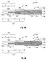
- Fig. 7A illustrates the feedline 120 and the radiating portion 118 of the triaxial antenna assembly 112 having a double-dipole antenna 140.
- the double-dipole antenna 140 is coupled to the feedline 120 that electrically connects the triaxial antenna assembly 112 to the generator 14.
- the radiating portion 118 includes an inner conductor 150 (e.g., a wire) surrounded by an inner insulator 152, which is surrounded by a central conductor 156 (e.g., a cylindrical conducting sheath).
- the radiating portion 118 also includes a central insulator 157 disposed around the central conductor 156, which is surrounded by an outer conductor 158.
- the inner, central and outer conductors 150, 156 and 158, respectively, may be constructed of copper, gold, stainless steel or other conductive metals with similar conductivity values. Much like the aforementioned conductors, the metals may be plated with other materials, e.g., other conductive materials, to improve their properties, e.g., to improve conductivity or decrease energy loss, etc.
- the outer conductor 158 may be surrounded by an outer jacket 159 defining a cavity 166 therebetween.
- the outer jacket 159 may be hollow and may include the cavity 166 inside thereof.
- the cavity 166 is in liquid communication with the ports 30 and 32 (see Fig. 6 ) for circulating the coolant fluid 37 therethrough.
- the outer conductor 158 may also include a solid conducting portion 168 disposed at the distal end thereof. The circulation of the coolant fluid 37 through the entire length of the cavity 166 that covers the feedline 120 removes the heat generated during ablation.
- the triaxial antenna assembly 112 is adapted to deliver microwave energy at two distinct frequencies (e.g., high frequency and low frequency).
- the inner and central conductors 150 and 156 represent the first dipole 170 of the double-dipole antenna 140, and are adapted to deliver microwave energy at a first frequency (e.g., 2450 MHz).
- the first dipole 170 and the outer conductor 158 represent the second dipole 172 of the double-dipole antenna 140 and are adapted to deliver microwave energy at a second frequency (e.g., 915 MHz).
- the central conductor 156 serves a dual purpose in the triaxial antenna assembly 112 - the central conductor 156 acts as an outer conductor for the inner conductor 150 during high frequency energy delivery and as an inner conductor for the outer conductor 158 during low frequency energy delivery.
- the inner conductor 150 extends outside the central conductor 156 by a first predetermined length a , which may be a quarter wavelength of the amplitude of the microwave energy supplied at 2450 MHz (e.g., ⁇ eHF /4, wherein HF is the first frequency or the high frequency).
- the central conductor 156 also extends outside the outer conductor 158 by the predetermined length a .
- the exposed sections of the inner and central conductors 150 and 156 define a high frequency radiating section 170 having a total length equal to the sum of lengths a (e.g., ⁇ eHF/2 ). More specifically, during application of high frequency microwave energy, the inner conductor 150 acts as a high frequency first pole 180a and the central conductor 156 acts as a high frequency second pole 180b for the first dipole 170 of the double-dipole antenna 140.
- the cooling cavity 166 extends from the proximal end of the conducting portion 168 along the feedline 120, covering the outer conductor 158.
- conductors 150 and 156 along with conducting portion 168 define a low frequency radiating section 172 having a total length of 2a + b .
- the length b may be any length suitable such that the sum of 2a + b represents a half wavelength of the amplitude of the microwave energy supplied at the low frequency (e.g., 915 MHz).
- the inner and central conductors 150 and 156 act as a low frequency first pole 182a
- the conducting portion 168 acts as a low frequency second pole 182b for the second dipole of the double-dipole antenna 140.
- the triaxial antenna assembly 112 includes a choke 160 that is disposed around the outer conductor 158.
- Choke 160 may include an inner dielectric layer 162 and an outer conductive layer 164.
- the choke 160 may be a quarter-wavelength shorted choke at the low frequency and is shorted to the outer conductor 158 at the proximal end of the choke 160 by soldering or other suitable methods.
- the choke 160 may replace the cooling cavity 166, and defines a portion of the radiating section 118 as a low frequency radiating section 172. More specifically, the choke 160 is disposed a second predetermined distance, length b , from the distal end of the inner conductor 150.
- Length b may be such that the sum of 2a + b represents half wavelength of the amplitude of the microwave energy supplied at 915 MHz (e.g., ⁇ eLF /2, wherein LF is the second frequency or the low frequency).
- the choke 160 is adapted to limit the bandwidth of the microwave energy only at the second frequency and does not interfere with the application of microwave energy at the first frequency.
- the inner and central conductors 150 and 156 act as a low frequency first pole 182a and a distal portion of the outer conductor 158 acts as a low frequency second pole 182b.
- the low frequency second pole 182b may have a length b such that in conjunction with the low frequency first pole 182a, the first and second poles 182a and 182b define a low frequency radiating section 172 having a total length equal to the sum of lengths 2a + b (e.g., ⁇ eLF /2).
- the dual-frequency operation of the antenna assembly 12 and the triaxial antenna assembly 112 allows for the production of lesions of varying shape and depth. More specifically, the total operative length (e.g., the resonating portion) of the antenna 40 of the assembly 12 ( Fig. 2 ) may be controlled by adjusting the frequency of the output of the generator 14. Since the depth of the lesion produced by the antenna 40 is directly related to the length of the resonating portion of the antenna 40, adjusting the relevant portions of the antenna 40 that resonate allows a user to control of the shape (e.g., diameter) and depth of the desired lesion.
- the shape e.g., diameter
- the shape of the lesion is controlled accordingly by nature of the inductor 74 disposed on the first pole 70 ( Fig. 5 ).
- the inductor 74 controls the operative length of the antenna 40 based on the frequency of the microwave energy supplied to the antenna 40.
- a method for forming a lesion includes the steps of supplying microwave energy at a predetermined frequency (e.g., first or second frequency) to the microwave antenna assembly 12 and adjusting the operative length of the dipole antenna 40 based on the frequency of the microwave energy supplied thereto to adjust at least one property (e.g., depth, circumference, shape, etc.) of the lesion.
- a predetermined frequency e.g., first or second frequency
- the depth of the desired lesion may also be varied.
- a low frequency e.g., 915 MHz
- the energy passes through the outer conductor 158 and the central conductor 156 thereby generating a lesion along the entire low frequency radiating section 172.
- a high frequency e.g., 2450 MHz
- the energy passes through the inner and central conductors 150 and 156, thereby generating a lesion only along the high frequency radiating section 170.
- energizing either or both sections 170 and 172 allows a user to generate varying depth lesions.
Description
- The present disclosure relates generally to microwave antennas used in tissue ablation procedures. More particularly, the present disclosure is directed to dipole microwave antennas having dual-band capability.
- Treatment of certain diseases requires destruction of malignant tissue growths (e.g., tumors). It is known that tumor cells denature at elevated temperatures that are slightly lower than temperatures injurious to surrounding healthy cells. Therefore, known treatment methods, such as hyperthermia therapy, heat tumor cells to temperatures above 41° C, while maintaining adjacent healthy cells at lower temperatures to avoid irreversible cell damage. Such methods involve applying electromagnetic radiation to heat tissue and include ablation and coagulation of tissue. In particular, microwave energy is used to coagulate and/or ablate tissue to denature or kill the cancerous cells.
- Microwave energy is applied via microwave ablation antennas that penetrate tissue to reach tumors. There are several types of microwave antennas, such as monopole and dipole, in which microwave energy radiates perpendicularly from the axis of the conductor. A monopole antenna includes a single, elongated microwave conductor whereas a dipole antenna includes two conductors. In a dipole antenna, the conductors may be in a coaxial configuration including an inner conductor and an outer conductor separated by a dielectric portion. More specifically, dipole microwave antennas may have a long, thin inner conductor that extends along a longitudinal axis of the antenna and is surrounded by an outer conductor. In certain variations, a portion or portions of the outer conductor may be selectively removed to provide more effective outward radiation of energy. This type of microwave antenna construction is typically referred to as a "leaky waveguide" or "leaky coaxial" antenna.
- Conventional microwave antennas operate at a single frequency allowing for creation of similarly shaped lesions (e.g., spherical, oblong, etc.). To obtain a different ablation shape, a different type of antenna is usually used.
-
US 4,583,556 discloses a microwave energy applicator that is arranged to apply microwave energy at dual frequencies. The preamble of claim 1 is based on this document. - According to an aspect of the present invnetion, a triaxial microwave antenna assembly is disclosed. The triaxial microwave antenna includes a feedline having an inner conductor, a central conductor disposed about the inner conductor and an outer conductor disposed about the central conductor and a radiating portion including a high frequency radiating section and a low frequency radiating section. Further features of the microwave antenna assembly of the present invention are defined in claim 1. A portion of the inner conductor may extend a first predetermined distance from the central conductor and a portion of the central conductor may extend the first predetermined distance from the outer conductor and a portion of the outer conductor may be a radiating portion thereof so that during application of a low frequency microwave energy, the portion of the inner conductor and the portion of the central conductor act as a low frequency first pole and the portion of the outer conductor acts as a low frequency second pole, the first and second low frequency poles defining the low frequency radiating section and so that during application of high frequency microwave energy, the portion of the inner conductor acts as a high frequency first pole and the portion of the central conductor acts as a high frequency second pole, the first and second high frequency poles defining the high frequency radiating section.
- A method for forming a lesion is also contemplated by the present disclosure. Such a method does not form an embodiment of the present invention. The method includes the initial step of providing a triaxial microwave antenna assembly that includes a radiating portion. The radiating portion includes a first frequency radiating section having a first predetermined length and a second frequency radiating section having a second predetermined length. The method also includes the step of supplying microwave either at a first frequency or a second frequency to selectively energize at least one of the first frequency radiating section and the second radiating section to adjust at least one property of the lection. The property of the lesion may include a depth and a diameter. The at least one property of the lesion may be selected from the group consisting of shape, diameter and depth. The method may include supplying microwave energy at a high frequency to energize the first frequency radiating section for the triaxial microwave antenna assembly. The method may also include supplying microwave energy at a low frequency to energize the second frequency radiating section of the triaxial microwave antenna assembly. The triaxial microwave antenna assembly of the providing step may include an inner conductor, a central conductor disposed about the inner conductor and an outer conductor disposed about the central conductor. The first radiating section of the providing step may include at least a portion of the inner conductor and at least a portion of the central conductor. The portion of the inner conductor may extend a first predetermined distance from the central conductor and the portion of the central conductor may extend the first predetermined distance from the outer conductor, such that the first predetermined length is equal to about twice the first predetermined distance. The first predetermined distance may be a quarter wavelength of the amplitude of the microwave energy supplied at the first frequency. The second radiating section of the providing step may include at least a portion of the central conductor and at least a portion of the outer conductor wherein the portion of the outer conductor is choked at a second predetermined distance. The second predetermined length is equal to about a sum of the first predetermined length and the second predetermined distance, which is a half wavelength of the amplitude of the microwave energy supplied a the second frequency.
- The above and other aspects, features, and advantages of the present disclosure will become more apparent in light of the following detailed description when taken in conjunction with the accompanying drawings in which:
-
Fig. 1 is a schematic diagram of a microwave ablation system according to the present disclosure; -
Fig. 2 is a perspective, internal view of the microwave antenna assembly ofFig. 1 according to the present disclosure; -
Fig. 3 is a cross-sectional side view of the microwave antenna assembly ofFig. 1 according to the present disclosure; -
Fig. 4 is a schematic diagram of the microwave antenna assembly ofFig. 1 according to the present disclosure; -
Fig. 5 is an isometric view of a radiating portion of the microwave antenna assembly ofFig. 1 according to the present disclosure; -
Fig. 6 is a schematic diagram of a microwave ablation system according to the present disclosure; and -
Figs. 7A and 7B are cross-sectional side views of the microwave antenna assembly ofFig. 6 according to the present disclosure. The microwave antenna assembly ofFig. 7B provides an embodiment of the present invention. - A particular embodiment of the present invnetion will be described herein below with reference to
Fig. 7B . In the following description, well-known functions or constructions are not described in detail to avoid obscuring the present disclosure in unnecessary detail. -
Fig.1 shows amicrowave ablation system 10 that includes amicrowave antenna assembly 12 coupled to amicrowave generator 14 via a flexiblecoaxial cable 16. Thegenerator 14 is configured to provide microwave energy at an operational frequency from about 500 MHz to about 5000 MHz. - In
Fig. 1 , theantenna assembly 12 includes aradiating portion 18 connected by feedline 20 (or shaft) to thecable 16.Sheath 38 encloses radiatingportion 18 andfeedline 20 allowing a coolant fluid to circulate around theantenna assembly 12. In another version, a solid dielectric material may be disposed therein. -
Fig. 2 illustrates theradiating portion 18 of theantenna assembly 12 having adipole antenna 40. Thedipole antenna 40 is coupled to thefeedline 20 that electrically connectsantenna assembly 12 to thegenerator 14. As shown inFig. 3 , thefeedline 20 includes an inner conductor 50 (e.g., a wire) surrounded by aninner insulator 52, which is, in turn, surrounded by an outer conductor 56 (e.g., a cylindrical conducting sheath). The inner andouter conductors feedline 20 may be formed from a coaxial semi-rigid or flexible cable having a wire with a 0.047" (1.2 mm) outer diameter rated for 50 Ohms. - The
dipole antenna 40 may be formed from theinner conductor 50 and theinner insulator 52, which are extended outside theouter conductor 56, as shown best inFig. 2 . In one version, in which thefeedline 20 is formed from a coaxial cable, theouter conductor 56 and theinner insulator 52 may be stripped to reveal theinner conductor 50, as shown inFig. 3 . -
Assembly 12 also includes atip 48 having atapered end 24 that terminates at apointed end 26 to allow for insertion into tissue with minimal resistance at a distal end of the radiatingportion 18. In those cases where the radiatingportion 18 is inserted into a pre-existing opening,tip 48 may be rounded or flat. - The
tip 48, which may be formed from a variety of heat-resistant materials suitable for penetrating tissue, such as metals (e.g., stainless steel) and various thermoplastic materials, such as poletherimide, polyamide thermoplastic resins, an example of which is Ultem® sold by General Electric Co. of Fairfield, CT. Thetip 48 may be machined from various stock rods to obtain a desired shape. Thetip 48 may be attached to thedistal portion 78 using various adhesives, such as epoxy seal. If thetip 48 is metal, thetip 48 may be soldered or welded to thedistal portion 78. - When microwave energy is applied to the
dipole antenna 40, the extended portion of theinner conductor 50 acts as afirst pole 70 and theouter conductor 56 acts as asecond pole 72, as represented inFig. 4 . As shown inFig. 5 , thefirst pole 70 includes aninductor 74 that maybe disposed between aproximal portion 76 and adistal portion 78 of thefirst pole 70. Thedistal portion 78 and theproximal portion 76 may be either balanced (e.g., of equal lengths) or unbalanced (e.g., of unequal lengths). - The second pole 72 (
Fig. 4 ) may have a first predetermined length a, that may be a quarter wavelength of the operating amplitude of thegenerator 14 at a first frequency. More specifically, thegenerator 14 may be adapted to operate at various frequencies, such as first and second frequencies, 2450 MHz and 915 MHz, respectively. Accordingly, the length a may be a quarter wavelength of the amplitude of the microwave energy supplied at 2450 MHz (e.g., λeHF/4, wherein HF is the first frequency or the high frequency). Other suitable frequencies are contemplated by the present disclosure. - The
proximal portion 76 of thefirst pole 70 may be substantially the same length, as thesecond pole 72, namely length a. Thedistal portion 78 may have a second predetermined length b, such that the total length of thefirst pole 70 may be length c, which is the sum of the lengths a and b. Length c may be a quarter wavelength of the operational amplitude of thegenerator 14 at the second frequency, namely 915 MHz (e.g., λeLF/4, wherein LF is the second frequency or the low frequency). Those skilled in the art will appreciate that the length of thesecond pole 72 and theproximal portion 76 as well as the total length of thefirst pole 70 are not limited to a quarter wavelength of the operating frequency and can be any suitable length maintaining the proportional length relationship discussed herein. - The
inductor 74, which may be a meandered strip or any suitable type of inductor, may have an impedance proportional to the frequency of the signal supplied by thegenerator 14, such that the impedance of theinductor 74 is relatively high when thegenerator 14 is operating at the first frequency (e.g., 2450 MHz) and lower when thegenerator 14 is outputting at the second frequency (e.g., 915 MHz). - At the first frequency, the impedance of the
inductor 74 is high and, therefore, blocks the high frequency microwave signal from reaching thedistal portion 78 of thefirst pole 70. As a result, the microwave signal energizes thesecond pole 72 and theproximal portion 76 of thefirst pole 70, hence only thesecond pole 72 and theproximal portion 76 resonate. In other words, first operative length (e.g., the total resonating length) of theantenna 40 is going to be the sum ofsecond pole 72 and theproximal portion 76 and is approximately half the wavelength of the operational amplitude of thegenerator 14 at the first frequency (e.g., λeHF/4 + λeHF/4 = λeHF/2). - At the second frequency, the impedance of the
inductor 74 is lower and, therefore, allows for propagation of the lower frequency microwave signal to thedistal portion 78. Since the microwave signal energizes thesecond pole 72 and thefirst pole 70 in its entirety, the first andsecond pole antenna 40 is the sum of thesecond pole 72 and thefirst pole 70 and is approximately half the wavelength of the operational amplitude of thegenerator 14 at the second frequency (e.g., λeLF/4 + λeHF/4). - Since the
antenna 40 is resonant at the first and second frequencies, the total length of thefirst pole 70 and thesecond pole 72 may be λeLF/2, in which case the length of thefirst pole 70 is not equal to λeLF/4. To ensure broadband behavior at both frequencies, a choke is not used. A coolant fluid may be supplied into the sheath 38 (Fig. 1 ) to limit ablation of tissue along the shaft of theassembly 12. -
Fig. 6 shows amicrowave ablation system 100 that includes a triaxialmicrowave antenna assembly 112 coupled to themicrowave generator 14 via the flexiblecoaxial cable 16. Thetriaxial antenna assembly 112 includes a radiatingportion 118 connected by feedline 120 (or shaft) to thecable 16. More specifically, thetriaxial antenna assembly 112 is coupled to thecable 16 through a connection hub 22 having anoutlet fluid port 30 and aninlet fluid port 32 allowing a coolant fluid 37 to circulate fromports triaxial antenna assembly 112. The coolant fluid 37 may be a dielectric coolant fluid such as deionized water or saline. Theports supply pump 34 that is, in turn, coupled to asupply tank 36 viasupply line 86. Thesupply pump 34 may be a peristaltic pump or any other suitable type. Thesupply tank 36 stores the coolant fluid 37 and may maintain the fluid at a predetermined temperature. More specifically, thesupply tank 36 may include a coolant unit which cools the returning liquid from thetriaxial antenna assembly 112. The coolant fluid 37 may be a gas and/or a mixture of fluid and gas. -
Fig. 7A illustrates thefeedline 120 and the radiatingportion 118 of thetriaxial antenna assembly 112 having a double-dipole antenna 140. The double-dipole antenna 140 is coupled to thefeedline 120 that electrically connects thetriaxial antenna assembly 112 to thegenerator 14. The radiatingportion 118 includes an inner conductor 150 (e.g., a wire) surrounded by aninner insulator 152, which is surrounded by a central conductor 156 (e.g., a cylindrical conducting sheath). The radiatingportion 118 also includes acentral insulator 157 disposed around thecentral conductor 156, which is surrounded by anouter conductor 158. The inner, central andouter conductors - The
outer conductor 158 may be surrounded by anouter jacket 159 defining acavity 166 therebetween. Theouter jacket 159 may be hollow and may include thecavity 166 inside thereof. Thecavity 166 is in liquid communication with theports 30 and 32 (seeFig. 6 ) for circulating the coolant fluid 37 therethrough. Theouter conductor 158 may also include asolid conducting portion 168 disposed at the distal end thereof. The circulation of the coolant fluid 37 through the entire length of thecavity 166 that covers thefeedline 120 removes the heat generated during ablation. - The
triaxial antenna assembly 112 is adapted to deliver microwave energy at two distinct frequencies (e.g., high frequency and low frequency). The inner andcentral conductors first dipole 170 of the double-dipole antenna 140, and are adapted to deliver microwave energy at a first frequency (e.g., 2450 MHz). Thefirst dipole 170 and theouter conductor 158 represent thesecond dipole 172 of the double-dipole antenna 140 and are adapted to deliver microwave energy at a second frequency (e.g., 915 MHz). Thus, thecentral conductor 156 serves a dual purpose in the triaxial antenna assembly 112 - thecentral conductor 156 acts as an outer conductor for theinner conductor 150 during high frequency energy delivery and as an inner conductor for theouter conductor 158 during low frequency energy delivery. - The
inner conductor 150 extends outside thecentral conductor 156 by a first predetermined length a, which may be a quarter wavelength of the amplitude of the microwave energy supplied at 2450 MHz (e.g., λeHF/4, wherein HF is the first frequency or the high frequency). Thecentral conductor 156 also extends outside theouter conductor 158 by the predetermined length a. During application of high frequency energy the exposed sections of the inner andcentral conductors frequency radiating section 170 having a total length equal to the sum of lengths a (e.g., λeHF/2). More specifically, during application of high frequency microwave energy, theinner conductor 150 acts as a high frequencyfirst pole 180a and thecentral conductor 156 acts as a high frequencysecond pole 180b for thefirst dipole 170 of the double-dipole antenna 140. - In
Fig. 7A , thecooling cavity 166 extends from the proximal end of the conductingportion 168 along thefeedline 120, covering theouter conductor 158. During application of low frequency energy,conductors portion 168 define a lowfrequency radiating section 172 having a total length of 2a + b. The length b may be any length suitable such that the sum of 2a + b represents a half wavelength of the amplitude of the microwave energy supplied at the low frequency (e.g., 915 MHz). During application of low frequency energy, the inner andcentral conductors first pole 182a, and the conductingportion 168 acts as a low frequencysecond pole 182b for the second dipole of the double-dipole antenna 140. - In accordance with an embodiment of the present invention and with reference to
Fig. 7B , thetriaxial antenna assembly 112 includes achoke 160 that is disposed around theouter conductor 158. Choke 160 may include aninner dielectric layer 162 and an outerconductive layer 164. Thechoke 160 may be a quarter-wavelength shorted choke at the low frequency and is shorted to theouter conductor 158 at the proximal end of thechoke 160 by soldering or other suitable methods. Thechoke 160 may replace thecooling cavity 166, and defines a portion of theradiating section 118 as a lowfrequency radiating section 172. More specifically, thechoke 160 is disposed a second predetermined distance, length b, from the distal end of theinner conductor 150. Length b may be such that the sum of 2a + b represents half wavelength of the amplitude of the microwave energy supplied at 915 MHz (e.g., λeLF/2, wherein LF is the second frequency or the low frequency). Thechoke 160 is adapted to limit the bandwidth of the microwave energy only at the second frequency and does not interfere with the application of microwave energy at the first frequency. - During application of low frequency microwave energy, the inner and
central conductors first pole 182a and a distal portion of theouter conductor 158 acts as a low frequencysecond pole 182b. The low frequencysecond pole 182b may have a length b such that in conjunction with the low frequencyfirst pole 182a, the first andsecond poles frequency radiating section 172 having a total length equal to the sum oflengths 2a + b (e.g., λeLF/2). - The dual-frequency operation of the
antenna assembly 12 and thetriaxial antenna assembly 112 allows for the production of lesions of varying shape and depth. More specifically, the total operative length (e.g., the resonating portion) of theantenna 40 of the assembly 12 (Fig. 2 ) may be controlled by adjusting the frequency of the output of thegenerator 14. Since the depth of the lesion produced by theantenna 40 is directly related to the length of the resonating portion of theantenna 40, adjusting the relevant portions of theantenna 40 that resonate allows a user to control of the shape (e.g., diameter) and depth of the desired lesion. In other words, by varying the frequency of the microwave signal supplied to theantenna 40 the shape of the lesion is controlled accordingly by nature of theinductor 74 disposed on the first pole 70 (Fig. 5 ). Theinductor 74 controls the operative length of theantenna 40 based on the frequency of the microwave energy supplied to theantenna 40. - A method for forming a lesion is also contemplated by the present disclosure. The method includes the steps of supplying microwave energy at a predetermined frequency (e.g., first or second frequency) to the
microwave antenna assembly 12 and adjusting the operative length of thedipole antenna 40 based on the frequency of the microwave energy supplied thereto to adjust at least one property (e.g., depth, circumference, shape, etc.) of the lesion. - With respect to the
triaxial antenna assembly 112 ofFig. 6 , the depth of the desired lesion may also be varied. By applying the microwave energy at a low frequency (e.g., 915 MHz) the energy passes through theouter conductor 158 and thecentral conductor 156 thereby generating a lesion along the entire lowfrequency radiating section 172. When applying microwave at a high frequency (e.g., 2450 MHz) the energy passes through the inner andcentral conductors frequency radiating section 170. As shown inFigs. 7A and 7B , energizing either or bothsections
Claims (8)
- A triaxial microwave antenna assembly (112) comprising:a feedline (120) including an inner conductor (150), a central conductor (156) disposed about the inner conductor (150) and an outer conductor (158) disposed about the central conductor; anda radiating portion (118) including a high frequency radiating section (170) and a low frequency radiating section (172);the assembly characterized by comprising:a choke (160) disposed around the outer conductor and adapted to limit the bandwidth of the microwave energy only at the low frequency and not to interfere with application of microwave energy at the high frequency.
- The triaxial microwave antenna assembly according to claim 1, wherein the high frequency radiating section includes a portion of the inner conductor and a portion of the central conductor and the low frequency radiating section includes the portion of the central conductor and a portion of the outer conductor.
- The triaxial microwave antenna assembly according to claim 2, wherein the portion of the inner conductor extends a first predetermined distance from the central conductor and the portion of the central conductor extends the first predetermined distance from the outer conductor.
- The microwave antenna assembly according to claim 3, wherein the first predetermined distance is a quarter wavelength of the amplitude of the microwave energy supplied at a high frequency.
- The microwave antenna assembly according to claim 2, 3 or 4, wherein the outer conductor includes a tubular structure defining a cavity (166) therein adapted to circulate a coolant fluid therethrough, wherein the cavity is disposed a second predetermined distance from the distal portion of the outer conductor.
- The microwave antenna assembly according to claim 5, wherein the sum of twice the first distance and the second predetermined distance is a half wavelength of the amplitude of the microwave energy supplied at a low frequency.
- The microwave antenna assembly according to claim 3 or 4, wherein the choke is disposed a second predetermined distance from the distal portion of the outer conductor.
- The microwave antenna assembly according to claim 7, wherein the sum of twice the first distance and the second predetermined distance is a half wavelength of the amplitude of the microwave energy supplied at a low frequency.
Applications Claiming Priority (1)
| Application Number | Priority Date | Filing Date | Title |
|---|---|---|---|
| US12/197,473 US9173706B2 (en) | 2008-08-25 | 2008-08-25 | Dual-band dipole microwave ablation antenna |
Publications (2)
| Publication Number | Publication Date |
|---|---|
| EP2158868A1 EP2158868A1 (en) | 2010-03-03 |
| EP2158868B1 true EP2158868B1 (en) | 2012-10-24 |
Family
ID=41170088
Family Applications (1)
| Application Number | Title | Priority Date | Filing Date |
|---|---|---|---|
| EP09010873A Active EP2158868B1 (en) | 2008-08-25 | 2009-08-25 | Dual-band dipole microwave ablation antenna |
Country Status (5)
| Country | Link |
|---|---|
| US (3) | US9173706B2 (en) |
| EP (1) | EP2158868B1 (en) |
| JP (1) | JP5420347B2 (en) |
| AU (1) | AU2009212766B2 (en) |
| CA (1) | CA2676522C (en) |
Cited By (6)
| Publication number | Priority date | Publication date | Assignee | Title |
|---|---|---|---|---|
| US8894640B2 (en) | 2009-09-24 | 2014-11-25 | Covidien Lp | Optical detection of interrupted fluid flow to ablation probe |
| US8932281B2 (en) | 2011-01-05 | 2015-01-13 | Covidien Lp | Energy-delivery devices with flexible fluid-cooled shaft, inflow/outflow junctions suitable for use with same, and systems including same |
| US9011421B2 (en) | 2011-01-05 | 2015-04-21 | Covidien Lp | Energy-delivery devices with flexible fluid-cooled shaft, inflow/outflow junctions suitable for use with same, and systems including same |
| US9017319B2 (en) | 2011-01-05 | 2015-04-28 | Covidien Lp | Energy-delivery devices with flexible fluid-cooled shaft, inflow/outflow junctions suitable for use with same, and systems including same |
| US9028476B2 (en) | 2011-02-03 | 2015-05-12 | Covidien Lp | Dual antenna microwave resection and ablation device, system and method of use |
| US9192437B2 (en) | 2009-05-27 | 2015-11-24 | Covidien Lp | Narrow gauge high strength choked wet tip microwave ablation antenna |
Families Citing this family (54)
| Publication number | Priority date | Publication date | Assignee | Title |
|---|---|---|---|---|
| US7197363B2 (en) * | 2002-04-16 | 2007-03-27 | Vivant Medical, Inc. | Microwave antenna having a curved configuration |
| US10363092B2 (en) | 2006-03-24 | 2019-07-30 | Neuwave Medical, Inc. | Transmission line with heat transfer ability |
| US10376314B2 (en) | 2006-07-14 | 2019-08-13 | Neuwave Medical, Inc. | Energy delivery systems and uses thereof |
| US11389235B2 (en) | 2006-07-14 | 2022-07-19 | Neuwave Medical, Inc. | Energy delivery systems and uses thereof |
| US9622813B2 (en) | 2007-11-01 | 2017-04-18 | Covidien Lp | Method for volume determination and geometric reconstruction |
| US8280525B2 (en) | 2007-11-16 | 2012-10-02 | Vivant Medical, Inc. | Dynamically matched microwave antenna for tissue ablation |
| US8435237B2 (en) | 2008-01-29 | 2013-05-07 | Covidien Lp | Polyp encapsulation system and method |
| US9949794B2 (en) | 2008-03-27 | 2018-04-24 | Covidien Lp | Microwave ablation devices including expandable antennas and methods of use |
| US8192427B2 (en) | 2008-06-09 | 2012-06-05 | Tyco Healthcare Group Lp | Surface ablation process with electrode cooling methods |
| US9173706B2 (en) * | 2008-08-25 | 2015-11-03 | Covidien Lp | Dual-band dipole microwave ablation antenna |
| US8251987B2 (en) | 2008-08-28 | 2012-08-28 | Vivant Medical, Inc. | Microwave antenna |
| US8403924B2 (en) | 2008-09-03 | 2013-03-26 | Vivant Medical, Inc. | Shielding for an isolation apparatus used in a microwave generator |
| US8197473B2 (en) | 2009-02-20 | 2012-06-12 | Vivant Medical, Inc. | Leaky-wave antennas for medical applications |
| US8202270B2 (en) | 2009-02-20 | 2012-06-19 | Vivant Medical, Inc. | Leaky-wave antennas for medical applications |
| US9277969B2 (en) | 2009-04-01 | 2016-03-08 | Covidien Lp | Microwave ablation system with user-controlled ablation size and method of use |
| US8463396B2 (en) | 2009-05-06 | 2013-06-11 | Covidien LLP | Power-stage antenna integrated system with high-strength shaft |
| US8235981B2 (en) | 2009-06-02 | 2012-08-07 | Vivant Medical, Inc. | Electrosurgical devices with directional radiation pattern |
| EP2459096B1 (en) | 2009-07-28 | 2014-10-22 | Neuwave Medical, Inc. | Ablation device |
| USD634010S1 (en) | 2009-08-05 | 2011-03-08 | Vivant Medical, Inc. | Medical device indicator guide |
| US9031668B2 (en) * | 2009-08-06 | 2015-05-12 | Covidien Lp | Vented positioner and spacer and method of use |
| US9113925B2 (en) * | 2009-09-09 | 2015-08-25 | Covidien Lp | System and method for performing an ablation procedure |
| US8069553B2 (en) | 2009-09-09 | 2011-12-06 | Vivant Medical, Inc. | Method for constructing a dipole antenna |
| US8355803B2 (en) | 2009-09-16 | 2013-01-15 | Vivant Medical, Inc. | Perfused core dielectrically loaded dipole microwave antenna probe |
| US9095359B2 (en) | 2009-09-18 | 2015-08-04 | Covidien Lp | Tissue ablation system with energy distribution |
| US9113926B2 (en) | 2009-09-29 | 2015-08-25 | Covidien Lp | Management of voltage standing wave ratio at skin surface during microwave ablation |
| US8556889B2 (en) | 2009-09-29 | 2013-10-15 | Covidien Lp | Flow rate monitor for fluid cooled microwave ablation probe |
| US8568401B2 (en) * | 2009-10-27 | 2013-10-29 | Covidien Lp | System for monitoring ablation size |
| US8382750B2 (en) * | 2009-10-28 | 2013-02-26 | Vivant Medical, Inc. | System and method for monitoring ablation size |
| US8430871B2 (en) | 2009-10-28 | 2013-04-30 | Covidien Lp | System and method for monitoring ablation size |
| US8491579B2 (en) * | 2010-02-05 | 2013-07-23 | Covidien Lp | Electrosurgical devices with choke shorted to biological tissue |
| US8409188B2 (en) * | 2010-03-26 | 2013-04-02 | Covidien Lp | Ablation devices with adjustable radiating section lengths, electrosurgical systems including same, and methods of adjusting ablation fields using same |
| ES2856026T3 (en) | 2010-05-03 | 2021-09-27 | Neuwave Medical Inc | Power supply systems |
| USD673685S1 (en) | 2010-09-08 | 2013-01-01 | Vivant Medical, Inc. | Microwave device spacer and positioner with arcuate slot |
| US8945144B2 (en) | 2010-09-08 | 2015-02-03 | Covidien Lp | Microwave spacers and method of use |
| US8968289B2 (en) | 2010-10-22 | 2015-03-03 | Covidien Lp | Microwave spacers and methods of use |
| US9770294B2 (en) | 2011-01-05 | 2017-09-26 | Covidien Lp | Energy-delivery devices with flexible fluid-cooled shaft, inflow/outflow junctions suitable for use with same, and systems including same |
| US10335230B2 (en) | 2011-03-09 | 2019-07-02 | Covidien Lp | Systems for thermal-feedback-controlled rate of fluid flow to fluid-cooled antenna assembly and methods of directing energy to tissue using same |
| EP3769712A1 (en) | 2011-12-21 | 2021-01-27 | Neuwave Medical, Inc. | Energy delivery systems |
| US9119648B2 (en) | 2012-01-06 | 2015-09-01 | Covidien Lp | System and method for treating tissue using an expandable antenna |
| US9113931B2 (en) | 2012-01-06 | 2015-08-25 | Covidien Lp | System and method for treating tissue using an expandable antenna |
| AU2013305759C1 (en) | 2012-08-23 | 2018-01-18 | Janssen Biopharma, Inc. | Compounds for the treatment of paramoxyvirus viral infections |
| MA41614A (en) * | 2015-02-25 | 2018-01-02 | Alios Biopharma Inc | ANTIVIRAL COMPOUNDS |
| US20170112588A1 (en) | 2015-10-26 | 2017-04-27 | Neuwave Medical, Inc. | Apparatuses for securing a medical device and related methods thereof |
| EP3367942B1 (en) | 2015-10-26 | 2021-01-20 | Neuwave Medical, Inc. | Energy delivery systems |
| GB2550537B (en) | 2016-02-11 | 2018-04-04 | Gyrus Medical Ltd | Microwave ablation antenna assemblies |
| ES2854935T3 (en) | 2016-04-15 | 2021-09-23 | Neuwave Medical Inc | Power delivery system |
| US11000332B2 (en) | 2016-08-02 | 2021-05-11 | Covidien Lp | Ablation cable assemblies having a large diameter coaxial feed cable reduced to a small diameter at intended site |
| US10716619B2 (en) | 2017-06-19 | 2020-07-21 | Covidien Lp | Microwave and radiofrequency energy-transmitting tissue ablation systems |
| US20190246876A1 (en) | 2018-02-15 | 2019-08-15 | Neuwave Medical, Inc. | Compositions and methods for directing endoscopic devices |
| US11672596B2 (en) * | 2018-02-26 | 2023-06-13 | Neuwave Medical, Inc. | Energy delivery devices with flexible and adjustable tips |
| US11160600B2 (en) | 2018-03-01 | 2021-11-02 | Covidien Lp | Monopolar return electrode grasper with return electrode monitoring |
| CN113206383A (en) * | 2018-07-26 | 2021-08-03 | 华为技术有限公司 | Feed source device, dual-frequency microwave antenna and dual-frequency antenna equipment |
| US11832879B2 (en) | 2019-03-08 | 2023-12-05 | Neuwave Medical, Inc. | Systems and methods for energy delivery |
| CN110701993B (en) * | 2019-09-29 | 2021-08-03 | 广州佳昕机电科技有限公司 | Antenna buried depth detection device and detection method of smart card |
Citations (1)
| Publication number | Priority date | Publication date | Assignee | Title |
|---|---|---|---|---|
| EP1055400A1 (en) * | 1999-05-28 | 2000-11-29 | Gyrus Medical Limited | An electrosurgical instrument |
Family Cites Families (146)
| Publication number | Priority date | Publication date | Assignee | Title |
|---|---|---|---|---|
| DE390937C (en) | 1922-10-13 | 1924-03-03 | Adolf Erb | Device for internal heating of furnace furnaces for hardening, tempering, annealing, quenching and melting |
| DE1099658B (en) | 1959-04-29 | 1961-02-16 | Siemens Reiniger Werke Ag | Automatic switch-on device for high-frequency surgical devices |
| FR1275415A (en) | 1960-09-26 | 1961-11-10 | Device for detecting disturbances for electrical installations, in particular electrosurgery | |
| DE1139927B (en) | 1961-01-03 | 1962-11-22 | Friedrich Laber | High-frequency surgical device |
| DE1149832C2 (en) | 1961-02-25 | 1977-10-13 | Siemens AG, 1000 Berlin und 8000 München | HIGH FREQUENCY SURGICAL EQUIPMENT |
| FR1347865A (en) | 1962-11-22 | 1964-01-04 | Improvements to diathermo-coagulation devices | |
| DE1439302B2 (en) | 1963-10-26 | 1971-05-19 | Siemens AG, 1000 Berlin u 8000 München | High frequency surgical device |
| US3631363A (en) | 1969-11-14 | 1971-12-28 | Gen Electric | High-frequency cavity oscillator having improved tuning means |
| SU401367A1 (en) | 1971-10-05 | 1973-10-12 | Тернопольский государственный медицинский институт | BIAKTIVNYE ELECTRO SURGICAL INSTRUMENT |
| FR2235669A1 (en) | 1973-07-07 | 1975-01-31 | Lunacek Boris | Gynaecological sterilisation instrument - has hollow electrode protruding from the end of a curved ended tube |
| GB1480736A (en) | 1973-08-23 | 1977-07-20 | Matburn Ltd | Electrodiathermy apparatus |
| DE2455174A1 (en) | 1973-11-21 | 1975-05-22 | Termiflex Corp | INPUT / OUTPUT DEVICE FOR DATA EXCHANGE WITH DATA PROCESSING DEVICES |
| DE2407559C3 (en) | 1974-02-16 | 1982-01-21 | Dornier System Gmbh, 7990 Friedrichshafen | Heat probe |
| DE2415263A1 (en) | 1974-03-29 | 1975-10-02 | Aesculap Werke Ag | Surgical H.F. coagulation probe has electrode tongs - with exposed ends of insulated conductors forming tong-jaws |
| DE2429021C2 (en) | 1974-06-18 | 1983-12-08 | Erbe Elektromedizin GmbH, 7400 Tübingen | Remote switching device for an HF surgical device |
| FR2276027A1 (en) | 1974-06-25 | 1976-01-23 | Medical Plastics Inc | Plate electrode with connector - is clamped between connector jaws held by releasable locking device |
| DE2460481A1 (en) | 1974-12-20 | 1976-06-24 | Delma Elektro Med App | Electrode grip for remote HF surgical instrument switching - has shaped insulated piece with contact ring of sterilizable (silicon) rubber |
| US4237887A (en) | 1975-01-23 | 1980-12-09 | Valleylab, Inc. | Electrosurgical device |
| DE2504280C3 (en) | 1975-02-01 | 1980-08-28 | Hans Heinrich Prof. Dr. 8035 Gauting Meinke | Device for cutting and / or coagulating human tissue with high frequency current |
| CA1064581A (en) | 1975-06-02 | 1979-10-16 | Stephen W. Andrews | Pulse control circuit and method for electrosurgical units |
| FR2315286A2 (en) | 1975-06-26 | 1977-01-21 | Lamidey Marcel | H.F. blood coagulating dissecting forceps - with adjustable stops to vary clamping space and circuit making contacts |
| DE2540968C2 (en) | 1975-09-13 | 1982-12-30 | Erbe Elektromedizin GmbH, 7400 Tübingen | Device for switching on the coagulation current of a bipolar coagulation forceps |
| FR2390968A1 (en) | 1977-05-16 | 1978-12-15 | Skovajsa Joseph | Local acupuncture treatment appts. - has oblong head with end aperture and contains laser diode unit (NL 20.11.78) |
| SU727201A2 (en) | 1977-11-02 | 1980-04-15 | Киевский Научно-Исследовательский Институт Нейрохирургии | Electric surgical apparatus |
| DE2803275C3 (en) | 1978-01-26 | 1980-09-25 | Aesculap-Werke Ag Vormals Jetter & Scheerer, 7200 Tuttlingen | Remote switching device for switching a monopolar HF surgical device |
| DE2823291A1 (en) | 1978-05-27 | 1979-11-29 | Rainer Ing Grad Koch | Coagulation instrument automatic HF switching circuit - has first lead to potentiometer and second to transistor base |
| DE2946728A1 (en) | 1979-11-20 | 1981-05-27 | Erbe Elektromedizin GmbH & Co KG, 7400 Tübingen | HF surgical appts. for use with endoscope - provides cutting or coagulation current at preset intervals and of selected duration |
| US5097844A (en) | 1980-04-02 | 1992-03-24 | Bsd Medical Corporation | Hyperthermia apparatus having three-dimensional focusing |
| US4798215A (en) | 1984-03-15 | 1989-01-17 | Bsd Medical Corporation | Hyperthermia apparatus |
| US4462412A (en) | 1980-04-02 | 1984-07-31 | Bsd Medical Corporation | Annular electromagnetic radiation applicator for biological tissue, and method |
| JPS5778844A (en) | 1980-11-04 | 1982-05-17 | Kogyo Gijutsuin | Lasre knife |
| DE3045996A1 (en) | 1980-12-05 | 1982-07-08 | Medic Eschmann Handelsgesellschaft für medizinische Instrumente mbH, 2000 Hamburg | Electro-surgical scalpel instrument - has power supply remotely controlled by surgeon |
| FR2502935B1 (en) | 1981-03-31 | 1985-10-04 | Dolley Roger | METHOD AND DEVICE FOR CONTROLLING THE COAGULATION OF TISSUES USING A HIGH FREQUENCY CURRENT |
| DE3120102A1 (en) | 1981-05-20 | 1982-12-09 | F.L. Fischer GmbH & Co, 7800 Freiburg | ARRANGEMENT FOR HIGH-FREQUENCY COAGULATION OF EGG WHITE FOR SURGICAL PURPOSES |
| US4397313A (en) | 1981-08-03 | 1983-08-09 | Clini-Therm Corporation | Multiple microwave applicator system and method for microwave hyperthermia treatment |
| FR2517953A1 (en) | 1981-12-10 | 1983-06-17 | Alvar Electronic | Diaphanometer for optical examination of breast tissue structure - measures tissue transparency using two plates and optical fibre bundle cooperating with photoelectric cells |
| US4583556A (en) * | 1982-12-13 | 1986-04-22 | M/A-Com, Inc. | Microwave applicator/receiver apparatus |
| FR2546409B1 (en) | 1983-05-26 | 1988-05-13 | Cgr Mev | HYPERTHERMIA APPARATUS |
| FR2573301B3 (en) | 1984-11-16 | 1987-04-30 | Lamidey Gilles | SURGICAL PLIERS AND ITS CONTROL AND CONTROL APPARATUS |
| DE3510586A1 (en) | 1985-03-23 | 1986-10-02 | Erbe Elektromedizin GmbH, 7400 Tübingen | Control device for a high-frequency surgical instrument |
| DE3604823C2 (en) | 1986-02-15 | 1995-06-01 | Lindenmeier Heinz | High frequency generator with automatic power control for high frequency surgery |
| JPH055106Y2 (en) | 1986-02-28 | 1993-02-09 | ||
| US5554176A (en) * | 1986-05-15 | 1996-09-10 | Telectronics Pacing Systems, Inc. | Implantable electrode and sensor lead apparatus |
| EP0246350A1 (en) | 1986-05-23 | 1987-11-25 | Erbe Elektromedizin GmbH. | Coagulation electrode |
| JPH0540112Y2 (en) | 1987-03-03 | 1993-10-12 | ||
| DE3711511C1 (en) | 1987-04-04 | 1988-06-30 | Hartmann & Braun Ag | Method for determining gas concentrations in a gas mixture and sensor for measuring thermal conductivity |
| DE8712328U1 (en) | 1987-09-11 | 1988-02-18 | Jakoubek, Franz, 7201 Emmingen-Liptingen, De | |
| AU3696989A (en) | 1988-05-18 | 1989-12-12 | Kasevich Associates, Inc. | Microwave balloon angioplasty |
| US5150717A (en) | 1988-11-10 | 1992-09-29 | Arye Rosen | Microwave aided balloon angioplasty with guide filament |
| DE3904558C2 (en) | 1989-02-15 | 1997-09-18 | Lindenmeier Heinz | Automatically power-controlled high-frequency generator for high-frequency surgery |
| DE3926934A1 (en) | 1989-08-16 | 1991-02-21 | Deutsches Krebsforsch | HYPERTHERMIC MICROWAVE APPLICATOR FOR WARMING A LIMITED ENVIRONMENT IN A DISSIPATIVE MEDIUM |
| DE3942998C2 (en) | 1989-12-27 | 1998-11-26 | Delma Elektro Med App | High frequency electrosurgical unit |
| JP2514450B2 (en) * | 1990-03-01 | 1996-07-10 | 原田工業株式会社 | Three-wave shared antenna for automobile with sleeve |
| US5221269A (en) | 1990-10-15 | 1993-06-22 | Cook Incorporated | Guide for localizing a nonpalpable breast lesion |
| US5301687A (en) * | 1991-06-06 | 1994-04-12 | Trustees Of Dartmouth College | Microwave applicator for transurethral hyperthermia |
| US5417210A (en) | 1992-05-27 | 1995-05-23 | International Business Machines Corporation | System and method for augmentation of endoscopic surgery |
| DE4122050C2 (en) | 1991-07-03 | 1996-05-30 | Gore W L & Ass Gmbh | Antenna arrangement with supply line for medical heat application in body cavities |
| US5366477A (en) | 1991-10-17 | 1994-11-22 | American Cyanamid Company | Actuating forces transmission link and assembly for use in surgical instruments |
| US5323778A (en) | 1991-11-05 | 1994-06-28 | Brigham & Women's Hospital | Method and apparatus for magnetic resonance imaging and heating tissues |
| DE4238263A1 (en) | 1991-11-15 | 1993-05-19 | Minnesota Mining & Mfg | Adhesive comprising hydrogel and crosslinked polyvinyl:lactam - is used in electrodes for biomedical application providing low impedance and good mechanical properties when water and/or moisture is absorbed from skin |
| US5681282A (en) | 1992-01-07 | 1997-10-28 | Arthrocare Corporation | Methods and apparatus for ablation of luminal tissues |
| DE4205213A1 (en) | 1992-02-20 | 1993-08-26 | Delma Elektro Med App | HIGH FREQUENCY SURGERY DEVICE |
| FR2687786B1 (en) | 1992-02-26 | 1994-05-06 | Pechiney Recherche | MEASUREMENT OF ELECTRICAL RESISTIVITY AND HIGH TEMPERATURE THERMAL CONDUCTIVITY OF REFRACTORY PRODUCTS. |
| CA2094220A1 (en) | 1992-05-21 | 1993-11-22 | Mark A. Rydell | Surgical scissors with bipolar coagulation feature |
| DE4303882C2 (en) | 1993-02-10 | 1995-02-09 | Kernforschungsz Karlsruhe | Combination instrument for separation and coagulation for minimally invasive surgery |
| GB9309142D0 (en) | 1993-05-04 | 1993-06-16 | Gyrus Medical Ltd | Laparoscopic instrument |
| US5405346A (en) | 1993-05-14 | 1995-04-11 | Fidus Medical Technology Corporation | Tunable microwave ablation catheter |
| US5693082A (en) | 1993-05-14 | 1997-12-02 | Fidus Medical Technology Corporation | Tunable microwave ablation catheter system and method |
| JPH07106840A (en) * | 1993-10-07 | 1995-04-21 | Harada Ind Co Ltd | Sleeve antenna in common use for two waves |
| GB9322464D0 (en) | 1993-11-01 | 1993-12-22 | Gyrus Medical Ltd | Electrosurgical apparatus |
| DE4339049C2 (en) | 1993-11-16 | 2001-06-28 | Erbe Elektromedizin | Surgical system configuration facility |
| GB9413070D0 (en) | 1994-06-29 | 1994-08-17 | Gyrus Medical Ltd | Electrosurgical apparatus |
| GB9425781D0 (en) | 1994-12-21 | 1995-02-22 | Gyrus Medical Ltd | Electrosurgical instrument |
| US6293942B1 (en) | 1995-06-23 | 2001-09-25 | Gyrus Medical Limited | Electrosurgical generator method |
| US6496738B2 (en) | 1995-09-06 | 2002-12-17 | Kenneth L. Carr | Dual frequency microwave heating apparatus |
| DE19608716C1 (en) | 1996-03-06 | 1997-04-17 | Aesculap Ag | Bipolar surgical holding instrument |
| EP0837716A1 (en) | 1996-05-06 | 1998-04-29 | Thermal Therapeutics, Inc. | Transcervical intrauterine applicator for intrauterine hyperthermia |
| AU3204097A (en) | 1996-05-22 | 1997-12-09 | Somnus Medical Technologies, Inc. | Method and apparatus for ablating turbinates |
| DE29616210U1 (en) | 1996-09-18 | 1996-11-14 | Winter & Ibe Olympus | Handle for surgical instruments |
| DE19643127A1 (en) | 1996-10-18 | 1998-04-23 | Berchtold Gmbh & Co Geb | High frequency surgical device and method for its operation |
| US5923475A (en) | 1996-11-27 | 1999-07-13 | Eastman Kodak Company | Laser printer using a fly's eye integrator |
| DE19717411A1 (en) | 1997-04-25 | 1998-11-05 | Aesculap Ag & Co Kg | Monitoring of thermal loading of patient tissue in contact region of neutral electrode of HF treatment unit |
| US6591049B2 (en) | 1997-07-02 | 2003-07-08 | Lumitex, Inc. | Light delivery systems and applications thereof |
| DE19751108A1 (en) | 1997-11-18 | 1999-05-20 | Beger Frank Michael Dipl Desig | Electrosurgical operation tool, especially for diathermy |
| US6031375A (en) | 1997-11-26 | 2000-02-29 | The Johns Hopkins University | Method of magnetic resonance analysis employing cylindrical coordinates and an associated apparatus |
| EP0923907A1 (en) | 1997-12-19 | 1999-06-23 | Gyrus Medical Limited | An electrosurgical instrument |
| DE19801173C1 (en) | 1998-01-15 | 1999-07-15 | Kendall Med Erzeugnisse Gmbh | Clamp connector for film electrodes |
| DE19848540A1 (en) | 1998-10-21 | 2000-05-25 | Reinhard Kalfhaus | Circuit layout and method for operating a single- or multiphase current inverter connects an AC voltage output to a primary winding and current and a working resistance to a transformer's secondary winding and current. |
| US7070595B2 (en) | 1998-12-14 | 2006-07-04 | Medwaves, Inc. | Radio-frequency based catheter system and method for ablating biological tissues |
| US6427089B1 (en) | 1999-02-19 | 2002-07-30 | Edward W. Knowlton | Stomach treatment apparatus and method |
| GB9904373D0 (en) * | 1999-02-25 | 1999-04-21 | Microsulis Plc | Radiation applicator |
| US20020022836A1 (en) | 1999-03-05 | 2002-02-21 | Gyrus Medical Limited | Electrosurgery system |
| US6287297B1 (en) | 1999-03-05 | 2001-09-11 | Plc Medical Systems, Inc. | Energy delivery system and method for performing myocardial revascular |
| US6375606B1 (en) | 1999-03-17 | 2002-04-23 | Stereotaxis, Inc. | Methods of and apparatus for treating vascular defects |
| GB9911956D0 (en) | 1999-05-21 | 1999-07-21 | Gyrus Medical Ltd | Electrosurgery system and method |
| GB9911954D0 (en) | 1999-05-21 | 1999-07-21 | Gyrus Medical Ltd | Electrosurgery system and instrument |
| GB9912625D0 (en) | 1999-05-28 | 1999-07-28 | Gyrus Medical Ltd | An electrosurgical generator and system |
| GB9913652D0 (en) | 1999-06-11 | 1999-08-11 | Gyrus Medical Ltd | An electrosurgical generator |
| WO2001001847A1 (en) | 1999-07-06 | 2001-01-11 | Inbae Yoon | Penetrating endoscope and endoscopic surgical instrument with cmos image sensor and display |
| WO2001064124A1 (en) | 2000-03-01 | 2001-09-07 | Surgical Navigation Technologies, Inc. | Multiple cannula image guided tool for image guided procedures |
| AU5113401A (en) | 2000-03-31 | 2001-10-15 | Rita Medical Systems Inc | Tissue biopsy and treatment apparatus and method |
| DE10027727C1 (en) | 2000-06-03 | 2001-12-06 | Aesculap Ag & Co Kg | Scissors-shaped or forceps-shaped surgical instrument |
| US6866624B2 (en) | 2000-12-08 | 2005-03-15 | Medtronic Ave,Inc. | Apparatus and method for treatment of malignant tumors |
| US6603994B2 (en) | 2000-12-28 | 2003-08-05 | Scimed Life Systems, Inc. | Apparatus and method for internally inducing a magnetic field in an aneurysm to embolize aneurysm with magnetically-controllable substance |
| ITPI20010006A1 (en) * | 2001-01-31 | 2002-07-31 | Cnr Consiglio Naz Delle Ricer | INTERSTITIAL ANTENNA WITH MINIATURIZED CHOKE FOR MICROWAVE HYPERTEMIA APPLICATIONS IN MEDICINE AND SURGERY |
| US20050014901A1 (en) * | 2001-07-10 | 2005-01-20 | Ips Corporation | Adhesive compositions for bonding and filling large assemblies |
| US6878147B2 (en) * | 2001-11-02 | 2005-04-12 | Vivant Medical, Inc. | High-strength microwave antenna assemblies |
| DE10224154A1 (en) | 2002-05-27 | 2003-12-18 | Celon Ag Medical Instruments | Application device for electrosurgical device for body tissue removal via of HF current has electrode subset selected from active electrode set in dependence on measured impedance of body tissue |
| WO2004052169A2 (en) | 2002-09-27 | 2004-06-24 | The Trustees Of Dartmouth College | Imaging by magnetic resonance adsorption, elastography and tomography |
| US7697972B2 (en) | 2002-11-19 | 2010-04-13 | Medtronic Navigation, Inc. | Navigation system for cardiac therapies |
| US6961028B2 (en) | 2003-01-17 | 2005-11-01 | Lockheed Martin Corporation | Low profile dual frequency dipole antenna structure |
| JP2004290266A (en) | 2003-03-25 | 2004-10-21 | Olympus Corp | Treating apparatus |
| US6932776B2 (en) * | 2003-06-02 | 2005-08-23 | Meridian Medicalssystems, Llc | Method and apparatus for detecting and treating vulnerable plaques |
| DE10328514B3 (en) | 2003-06-20 | 2005-03-03 | Aesculap Ag & Co. Kg | Endoscopic surgical scissor instrument has internal pushrod terminating at distal end in transverse cylindrical head |
| GB2403148C2 (en) | 2003-06-23 | 2013-02-13 | Microsulis Ltd | Radiation applicator |
| US7311703B2 (en) * | 2003-07-18 | 2007-12-25 | Vivant Medical, Inc. | Devices and methods for cooling microwave antennas |
| FR2862813B1 (en) | 2003-11-20 | 2006-06-02 | Pellenc Sa | METHOD FOR BALANCED LOADING OF LITHIUM-ION OR POLYMER LITHIUM BATTERY |
| FR2864439B1 (en) | 2003-12-30 | 2010-12-03 | Image Guided Therapy | DEVICE FOR TREATING A VOLUME OF BIOLOGICAL TISSUE BY LOCALIZED HYPERTHERMIA |
| JP4133855B2 (en) * | 2004-02-03 | 2008-08-13 | Dxアンテナ株式会社 | Multi-frequency antenna |
| US6999041B2 (en) | 2004-02-16 | 2006-02-14 | The Boeing Company | Dual frequency antennas and associated down-conversion method |
| US6950076B2 (en) | 2004-02-16 | 2005-09-27 | The Boeing Company | Two-dimensional dual-frequency antenna and associated down-conversion method |
| US7244254B2 (en) | 2004-04-29 | 2007-07-17 | Micrablate | Air-core microwave ablation antennas |
| US7101369B2 (en) * | 2004-04-29 | 2006-09-05 | Wisconsin Alumni Research Foundation | Triaxial antenna for microwave tissue ablation |
| US7467015B2 (en) | 2004-04-29 | 2008-12-16 | Neuwave Medical, Inc. | Segmented catheter for tissue ablation |
| DE102004022206B4 (en) | 2004-05-04 | 2006-05-11 | Bundesrepublik Deutschland, vertr. d. d. Bundesministerium für Wirtschaft und Arbeit, dieses vertr. d. d. Präsidenten der Physikalisch-Technischen Bundesanstalt | Sensor for measuring thermal conductivity comprises a strip composed of two parallel sections, and two outer heating strips |
| TWI279030B (en) | 2004-06-21 | 2007-04-11 | Accton Technology Corp | Antenna and antenna array |
| WO2006127847A2 (en) | 2005-05-24 | 2006-11-30 | Micrablate, Llc | Microwave surgical device |
| WO2006138382A2 (en) | 2005-06-14 | 2006-12-28 | Micrablate, Llc | Microwave tissue resection tool |
| DE202005015147U1 (en) | 2005-09-26 | 2006-02-09 | Health & Life Co., Ltd., Chung-Ho | Biosensor test strip with identifying function for biological measuring instruments has functioning electrode and counter electrode, identification zones with coating of electrically conductive material and reaction zone |
| US7565207B2 (en) | 2005-11-22 | 2009-07-21 | Bsd Medical Corporation | Apparatus for creating hyperthermia in tissue |
| US8882766B2 (en) | 2006-01-24 | 2014-11-11 | Covidien Ag | Method and system for controlling delivery of energy to divide tissue |
| US10363092B2 (en) | 2006-03-24 | 2019-07-30 | Neuwave Medical, Inc. | Transmission line with heat transfer ability |
| US7777130B2 (en) | 2007-06-18 | 2010-08-17 | Vivant Medical, Inc. | Microwave cable cooling |
| US9949794B2 (en) | 2008-03-27 | 2018-04-24 | Covidien Lp | Microwave ablation devices including expandable antennas and methods of use |
| US9198723B2 (en) | 2008-03-31 | 2015-12-01 | Covidien Lp | Re-hydration antenna for ablation |
| US8834409B2 (en) | 2008-07-29 | 2014-09-16 | Covidien Lp | Method for ablation volume determination and geometric reconstruction |
| US9173706B2 (en) | 2008-08-25 | 2015-11-03 | Covidien Lp | Dual-band dipole microwave ablation antenna |
| US8118808B2 (en) | 2009-03-10 | 2012-02-21 | Vivant Medical, Inc. | Cooled dielectrically buffered microwave dipole antenna |
| US9277969B2 (en) | 2009-04-01 | 2016-03-08 | Covidien Lp | Microwave ablation system with user-controlled ablation size and method of use |
| US10045819B2 (en) | 2009-04-14 | 2018-08-14 | Covidien Lp | Frequency identification for microwave ablation probes |
| US8463396B2 (en) | 2009-05-06 | 2013-06-11 | Covidien LLP | Power-stage antenna integrated system with high-strength shaft |
| US8216227B2 (en) | 2009-05-06 | 2012-07-10 | Vivant Medical, Inc. | Power-stage antenna integrated system with junction member |
| US8353903B2 (en) | 2009-05-06 | 2013-01-15 | Vivant Medical, Inc. | Power-stage antenna integrated system |
| US8292881B2 (en) | 2009-05-27 | 2012-10-23 | Vivant Medical, Inc. | Narrow gauge high strength choked wet tip microwave ablation antenna |
| US8834460B2 (en) | 2009-05-29 | 2014-09-16 | Covidien Lp | Microwave ablation safety pad, microwave safety pad system and method of use |
| US8235981B2 (en) | 2009-06-02 | 2012-08-07 | Vivant Medical, Inc. | Electrosurgical devices with directional radiation pattern |
-
2008
- 2008-08-25 US US12/197,473 patent/US9173706B2/en active Active
-
2009
- 2009-08-24 CA CA2676522A patent/CA2676522C/en not_active Expired - Fee Related
- 2009-08-24 AU AU2009212766A patent/AU2009212766B2/en not_active Ceased
- 2009-08-24 JP JP2009193371A patent/JP5420347B2/en active Active
- 2009-08-25 EP EP09010873A patent/EP2158868B1/en active Active
-
2015
- 2015-10-27 US US14/923,868 patent/US9439730B2/en active Active
-
2016
- 2016-08-24 US US15/245,301 patent/US20160361118A1/en not_active Abandoned
Patent Citations (1)
| Publication number | Priority date | Publication date | Assignee | Title |
|---|---|---|---|---|
| EP1055400A1 (en) * | 1999-05-28 | 2000-11-29 | Gyrus Medical Limited | An electrosurgical instrument |
Cited By (6)
| Publication number | Priority date | Publication date | Assignee | Title |
|---|---|---|---|---|
| US9192437B2 (en) | 2009-05-27 | 2015-11-24 | Covidien Lp | Narrow gauge high strength choked wet tip microwave ablation antenna |
| US8894640B2 (en) | 2009-09-24 | 2014-11-25 | Covidien Lp | Optical detection of interrupted fluid flow to ablation probe |
| US8932281B2 (en) | 2011-01-05 | 2015-01-13 | Covidien Lp | Energy-delivery devices with flexible fluid-cooled shaft, inflow/outflow junctions suitable for use with same, and systems including same |
| US9011421B2 (en) | 2011-01-05 | 2015-04-21 | Covidien Lp | Energy-delivery devices with flexible fluid-cooled shaft, inflow/outflow junctions suitable for use with same, and systems including same |
| US9017319B2 (en) | 2011-01-05 | 2015-04-28 | Covidien Lp | Energy-delivery devices with flexible fluid-cooled shaft, inflow/outflow junctions suitable for use with same, and systems including same |
| US9028476B2 (en) | 2011-02-03 | 2015-05-12 | Covidien Lp | Dual antenna microwave resection and ablation device, system and method of use |
Also Published As
| Publication number | Publication date |
|---|---|
| US9439730B2 (en) | 2016-09-13 |
| US20160361118A1 (en) | 2016-12-15 |
| JP2010050975A (en) | 2010-03-04 |
| US20100045558A1 (en) | 2010-02-25 |
| JP5420347B2 (en) | 2014-02-19 |
| US9173706B2 (en) | 2015-11-03 |
| CA2676522C (en) | 2016-11-29 |
| AU2009212766B2 (en) | 2013-09-19 |
| AU2009212766A1 (en) | 2010-03-11 |
| EP2158868A1 (en) | 2010-03-03 |
| CA2676522A1 (en) | 2010-02-25 |
| US20160045260A1 (en) | 2016-02-18 |
Similar Documents
| Publication | Publication Date | Title |
|---|---|---|
| EP2158868B1 (en) | Dual-band dipole microwave ablation antenna | |
| US20100045559A1 (en) | Dual-Band Dipole Microwave Ablation Antenna | |
| EP2008604B1 (en) | Broadband microwave applicator | |
| EP2177173B1 (en) | Choked dielectric loaded tip dipole microwave antenna | |
| EP2128929B1 (en) | Slidable choke microwave antenna | |
| EP2245702B1 (en) | Choked dielectric loaded tip dipole microwave antenna | |
| AU2017219068B2 (en) | Dual-band dipole microwave ablation antenna | |
| AU2013273707B2 (en) | Dual-band dipole microwave ablation antenna | |
| AU2015261719B2 (en) | Slidable choke microwave antenna | |
| AU2014201120B2 (en) | Slidable choke microwave antenna |
Legal Events
| Date | Code | Title | Description |
|---|---|---|---|
| PUAI | Public reference made under article 153(3) epc to a published international application that has entered the european phase |
Free format text: ORIGINAL CODE: 0009012 |
|
| AK | Designated contracting states |
Kind code of ref document: A1 Designated state(s): AT BE BG CH CY CZ DE DK EE ES FI FR GB GR HR HU IE IS IT LI LT LU LV MC MK MT NL NO PL PT RO SE SI SK SM TR |
|
| AX | Request for extension of the european patent |
Extension state: AL BA RS |
|
| 17P | Request for examination filed |
Effective date: 20100902 |
|
| 17Q | First examination report despatched |
Effective date: 20101020 |
|
| GRAP | Despatch of communication of intention to grant a patent |
Free format text: ORIGINAL CODE: EPIDOSNIGR1 |
|
| GRAS | Grant fee paid |
Free format text: ORIGINAL CODE: EPIDOSNIGR3 |
|
| GRAA | (expected) grant |
Free format text: ORIGINAL CODE: 0009210 |
|
| AK | Designated contracting states |
Kind code of ref document: B1 Designated state(s): AT BE BG CH CY CZ DE DK EE ES FI FR GB GR HR HU IE IS IT LI LT LU LV MC MK MT NL NO PL PT RO SE SI SK SM TR |
|
| REG | Reference to a national code |
Ref country code: GB Ref legal event code: FG4D |
|
| REG | Reference to a national code |
Ref country code: CH Ref legal event code: EP |
|
| REG | Reference to a national code |
Ref country code: AT Ref legal event code: REF Ref document number: 580474 Country of ref document: AT Kind code of ref document: T Effective date: 20121115 |
|
| REG | Reference to a national code |
Ref country code: IE Ref legal event code: FG4D |
|
| REG | Reference to a national code |
Ref country code: DE Ref legal event code: R096 Ref document number: 602009010573 Country of ref document: DE Effective date: 20121220 |
|
| REG | Reference to a national code |
Ref country code: AT Ref legal event code: MK05 Ref document number: 580474 Country of ref document: AT Kind code of ref document: T Effective date: 20121024 |
|
| REG | Reference to a national code |
Ref country code: NL Ref legal event code: VDEP Effective date: 20121024 |
|
| PG25 | Lapsed in a contracting state [announced via postgrant information from national office to epo] |
Ref country code: NO Free format text: LAPSE BECAUSE OF FAILURE TO SUBMIT A TRANSLATION OF THE DESCRIPTION OR TO PAY THE FEE WITHIN THE PRESCRIBED TIME-LIMIT Effective date: 20130124 Ref country code: SE Free format text: LAPSE BECAUSE OF FAILURE TO SUBMIT A TRANSLATION OF THE DESCRIPTION OR TO PAY THE FEE WITHIN THE PRESCRIBED TIME-LIMIT Effective date: 20121024 Ref country code: NL Free format text: LAPSE BECAUSE OF FAILURE TO SUBMIT A TRANSLATION OF THE DESCRIPTION OR TO PAY THE FEE WITHIN THE PRESCRIBED TIME-LIMIT Effective date: 20121024 Ref country code: IS Free format text: LAPSE BECAUSE OF FAILURE TO SUBMIT A TRANSLATION OF THE DESCRIPTION OR TO PAY THE FEE WITHIN THE PRESCRIBED TIME-LIMIT Effective date: 20130224 Ref country code: FI Free format text: LAPSE BECAUSE OF FAILURE TO SUBMIT A TRANSLATION OF THE DESCRIPTION OR TO PAY THE FEE WITHIN THE PRESCRIBED TIME-LIMIT Effective date: 20121024 Ref country code: HR Free format text: LAPSE BECAUSE OF FAILURE TO SUBMIT A TRANSLATION OF THE DESCRIPTION OR TO PAY THE FEE WITHIN THE PRESCRIBED TIME-LIMIT Effective date: 20121024 |
|
| PG25 | Lapsed in a contracting state [announced via postgrant information from national office to epo] |
Ref country code: GR Free format text: LAPSE BECAUSE OF FAILURE TO SUBMIT A TRANSLATION OF THE DESCRIPTION OR TO PAY THE FEE WITHIN THE PRESCRIBED TIME-LIMIT Effective date: 20130125 Ref country code: LV Free format text: LAPSE BECAUSE OF FAILURE TO SUBMIT A TRANSLATION OF THE DESCRIPTION OR TO PAY THE FEE WITHIN THE PRESCRIBED TIME-LIMIT Effective date: 20121024 Ref country code: BE Free format text: LAPSE BECAUSE OF FAILURE TO SUBMIT A TRANSLATION OF THE DESCRIPTION OR TO PAY THE FEE WITHIN THE PRESCRIBED TIME-LIMIT Effective date: 20121024 Ref country code: SI Free format text: LAPSE BECAUSE OF FAILURE TO SUBMIT A TRANSLATION OF THE DESCRIPTION OR TO PAY THE FEE WITHIN THE PRESCRIBED TIME-LIMIT Effective date: 20121024 Ref country code: PL Free format text: LAPSE BECAUSE OF FAILURE TO SUBMIT A TRANSLATION OF THE DESCRIPTION OR TO PAY THE FEE WITHIN THE PRESCRIBED TIME-LIMIT Effective date: 20121024 Ref country code: PT Free format text: LAPSE BECAUSE OF FAILURE TO SUBMIT A TRANSLATION OF THE DESCRIPTION OR TO PAY THE FEE WITHIN THE PRESCRIBED TIME-LIMIT Effective date: 20130225 |
|
| PG25 | Lapsed in a contracting state [announced via postgrant information from national office to epo] |
Ref country code: AT Free format text: LAPSE BECAUSE OF FAILURE TO SUBMIT A TRANSLATION OF THE DESCRIPTION OR TO PAY THE FEE WITHIN THE PRESCRIBED TIME-LIMIT Effective date: 20121024 |
|
| PG25 | Lapsed in a contracting state [announced via postgrant information from national office to epo] |
Ref country code: BG Free format text: LAPSE BECAUSE OF FAILURE TO SUBMIT A TRANSLATION OF THE DESCRIPTION OR TO PAY THE FEE WITHIN THE PRESCRIBED TIME-LIMIT Effective date: 20130124 Ref country code: EE Free format text: LAPSE BECAUSE OF FAILURE TO SUBMIT A TRANSLATION OF THE DESCRIPTION OR TO PAY THE FEE WITHIN THE PRESCRIBED TIME-LIMIT Effective date: 20121024 Ref country code: CZ Free format text: LAPSE BECAUSE OF FAILURE TO SUBMIT A TRANSLATION OF THE DESCRIPTION OR TO PAY THE FEE WITHIN THE PRESCRIBED TIME-LIMIT Effective date: 20121024 Ref country code: SK Free format text: LAPSE BECAUSE OF FAILURE TO SUBMIT A TRANSLATION OF THE DESCRIPTION OR TO PAY THE FEE WITHIN THE PRESCRIBED TIME-LIMIT Effective date: 20121024 Ref country code: DK Free format text: LAPSE BECAUSE OF FAILURE TO SUBMIT A TRANSLATION OF THE DESCRIPTION OR TO PAY THE FEE WITHIN THE PRESCRIBED TIME-LIMIT Effective date: 20121024 |
|
| PG25 | Lapsed in a contracting state [announced via postgrant information from national office to epo] |
Ref country code: IT Free format text: LAPSE BECAUSE OF FAILURE TO SUBMIT A TRANSLATION OF THE DESCRIPTION OR TO PAY THE FEE WITHIN THE PRESCRIBED TIME-LIMIT Effective date: 20121024 Ref country code: RO Free format text: LAPSE BECAUSE OF FAILURE TO SUBMIT A TRANSLATION OF THE DESCRIPTION OR TO PAY THE FEE WITHIN THE PRESCRIBED TIME-LIMIT Effective date: 20121024 |
|
| PLBE | No opposition filed within time limit |
Free format text: ORIGINAL CODE: 0009261 |
|
| STAA | Information on the status of an ep patent application or granted ep patent |
Free format text: STATUS: NO OPPOSITION FILED WITHIN TIME LIMIT |
|
| 26N | No opposition filed |
Effective date: 20130725 |
|
| PG25 | Lapsed in a contracting state [announced via postgrant information from national office to epo] |
Ref country code: ES Free format text: LAPSE BECAUSE OF FAILURE TO SUBMIT A TRANSLATION OF THE DESCRIPTION OR TO PAY THE FEE WITHIN THE PRESCRIBED TIME-LIMIT Effective date: 20130204 |
|
| REG | Reference to a national code |
Ref country code: DE Ref legal event code: R082 Ref document number: 602009010573 Country of ref document: DE Representative=s name: HOFFMANN - EITLE, DE Effective date: 20130926 Ref country code: DE Ref legal event code: R081 Ref document number: 602009010573 Country of ref document: DE Owner name: COVIDIEN LP, US Free format text: FORMER OWNER: VIVANT MEDICAL, INC., BOULDER, US Effective date: 20130926 Ref country code: DE Ref legal event code: R081 Ref document number: 602009010573 Country of ref document: DE Owner name: COVIDIEN LP, MANSFIELD, US Free format text: FORMER OWNER: VIVANT MEDICAL, INC., BOULDER, COL., US Effective date: 20130926 Ref country code: DE Ref legal event code: R082 Ref document number: 602009010573 Country of ref document: DE Representative=s name: HOFFMANN - EITLE PATENT- UND RECHTSANWAELTE PA, DE Effective date: 20130926 |
|
| REG | Reference to a national code |
Ref country code: DE Ref legal event code: R097 Ref document number: 602009010573 Country of ref document: DE Effective date: 20130725 |
|
| PG25 | Lapsed in a contracting state [announced via postgrant information from national office to epo] |
Ref country code: CY Free format text: LAPSE BECAUSE OF FAILURE TO SUBMIT A TRANSLATION OF THE DESCRIPTION OR TO PAY THE FEE WITHIN THE PRESCRIBED TIME-LIMIT Effective date: 20121024 |
|
| REG | Reference to a national code |
Ref country code: GB Ref legal event code: 732E Free format text: REGISTERED BETWEEN 20131114 AND 20131120 |
|
| REG | Reference to a national code |
Ref country code: FR Ref legal event code: TP Owner name: COVIDIEN LP., US Effective date: 20131202 Ref country code: FR Ref legal event code: CD Owner name: COVIDIEN LP., US Effective date: 20131202 |
|
| REG | Reference to a national code |
Ref country code: CH Ref legal event code: PL |
|
| PG25 | Lapsed in a contracting state [announced via postgrant information from national office to epo] |
Ref country code: LI Free format text: LAPSE BECAUSE OF NON-PAYMENT OF DUE FEES Effective date: 20130831 Ref country code: CH Free format text: LAPSE BECAUSE OF NON-PAYMENT OF DUE FEES Effective date: 20130831 Ref country code: MC Free format text: LAPSE BECAUSE OF FAILURE TO SUBMIT A TRANSLATION OF THE DESCRIPTION OR TO PAY THE FEE WITHIN THE PRESCRIBED TIME-LIMIT Effective date: 20121024 |
|
| PG25 | Lapsed in a contracting state [announced via postgrant information from national office to epo] |
Ref country code: LT Free format text: LAPSE BECAUSE OF FAILURE TO SUBMIT A TRANSLATION OF THE DESCRIPTION OR TO PAY THE FEE WITHIN THE PRESCRIBED TIME-LIMIT Effective date: 20121024 |
|
| PG25 | Lapsed in a contracting state [announced via postgrant information from national office to epo] |
Ref country code: SM Free format text: LAPSE BECAUSE OF FAILURE TO SUBMIT A TRANSLATION OF THE DESCRIPTION OR TO PAY THE FEE WITHIN THE PRESCRIBED TIME-LIMIT Effective date: 20121024 |
|
| PG25 | Lapsed in a contracting state [announced via postgrant information from national office to epo] |
Ref country code: MT Free format text: LAPSE BECAUSE OF FAILURE TO SUBMIT A TRANSLATION OF THE DESCRIPTION OR TO PAY THE FEE WITHIN THE PRESCRIBED TIME-LIMIT Effective date: 20121024 Ref country code: TR Free format text: LAPSE BECAUSE OF FAILURE TO SUBMIT A TRANSLATION OF THE DESCRIPTION OR TO PAY THE FEE WITHIN THE PRESCRIBED TIME-LIMIT Effective date: 20121024 |
|
| PG25 | Lapsed in a contracting state [announced via postgrant information from national office to epo] |
Ref country code: MK Free format text: LAPSE BECAUSE OF FAILURE TO SUBMIT A TRANSLATION OF THE DESCRIPTION OR TO PAY THE FEE WITHIN THE PRESCRIBED TIME-LIMIT Effective date: 20121024 Ref country code: HU Free format text: LAPSE BECAUSE OF FAILURE TO SUBMIT A TRANSLATION OF THE DESCRIPTION OR TO PAY THE FEE WITHIN THE PRESCRIBED TIME-LIMIT; INVALID AB INITIO Effective date: 20090825 Ref country code: LU Free format text: LAPSE BECAUSE OF NON-PAYMENT OF DUE FEES Effective date: 20130825 |
|
| REG | Reference to a national code |
Ref country code: FR Ref legal event code: PLFP Year of fee payment: 8 |
|
| REG | Reference to a national code |
Ref country code: FR Ref legal event code: PLFP Year of fee payment: 9 |
|
| REG | Reference to a national code |
Ref country code: FR Ref legal event code: PLFP Year of fee payment: 10 |
|
| PGFP | Annual fee paid to national office [announced via postgrant information from national office to epo] |
Ref country code: GB Payment date: 20200722 Year of fee payment: 12 |
|
| PGFP | Annual fee paid to national office [announced via postgrant information from national office to epo] |
Ref country code: IE Payment date: 20210722 Year of fee payment: 13 |
|
| GBPC | Gb: european patent ceased through non-payment of renewal fee |
Effective date: 20210825 |
|
| PG25 | Lapsed in a contracting state [announced via postgrant information from national office to epo] |
Ref country code: GB Free format text: LAPSE BECAUSE OF NON-PAYMENT OF DUE FEES Effective date: 20210825 |
|
| PG25 | Lapsed in a contracting state [announced via postgrant information from national office to epo] |
Ref country code: IE Free format text: LAPSE BECAUSE OF NON-PAYMENT OF DUE FEES Effective date: 20220825 |
|
| PGFP | Annual fee paid to national office [announced via postgrant information from national office to epo] |
Ref country code: FR Payment date: 20230720 Year of fee payment: 15 Ref country code: DE Payment date: 20230720 Year of fee payment: 15 |