EP2172241A2 - Deflectable catheter with bonded center strut and method of manufacture for same - Google Patents
Deflectable catheter with bonded center strut and method of manufacture for same Download PDFInfo
- Publication number
- EP2172241A2 EP2172241A2 EP09252148A EP09252148A EP2172241A2 EP 2172241 A2 EP2172241 A2 EP 2172241A2 EP 09252148 A EP09252148 A EP 09252148A EP 09252148 A EP09252148 A EP 09252148A EP 2172241 A2 EP2172241 A2 EP 2172241A2
- Authority
- EP
- European Patent Office
- Prior art keywords
- catheter
- strut
- tubular member
- tip
- distal
- Prior art date
- Legal status (The legal status is an assumption and is not a legal conclusion. Google has not performed a legal analysis and makes no representation as to the accuracy of the status listed.)
- Granted
Links
- 238000000034 method Methods 0.000 title claims abstract description 22
- 238000004519 manufacturing process Methods 0.000 title claims description 10
- 239000002131 composite material Substances 0.000 claims abstract description 15
- 230000008878 coupling Effects 0.000 claims description 13
- 238000010168 coupling process Methods 0.000 claims description 13
- 238000005859 coupling reaction Methods 0.000 claims description 13
- 230000002262 irrigation Effects 0.000 claims description 12
- 238000003973 irrigation Methods 0.000 claims description 12
- 238000010438 heat treatment Methods 0.000 claims description 7
- 239000007787 solid Substances 0.000 claims description 6
- 239000011248 coating agent Substances 0.000 claims description 3
- 238000000576 coating method Methods 0.000 claims description 3
- 238000004891 communication Methods 0.000 claims description 2
- 238000005553 drilling Methods 0.000 claims description 2
- 230000004044 response Effects 0.000 claims description 2
- 238000007788 roughening Methods 0.000 claims description 2
- 239000012815 thermoplastic material Substances 0.000 claims 3
- 238000003780 insertion Methods 0.000 claims 1
- 230000037431 insertion Effects 0.000 claims 1
- 238000012544 monitoring process Methods 0.000 claims 1
- 229920001169 thermoplastic Polymers 0.000 abstract description 3
- 239000004416 thermosoftening plastic Substances 0.000 abstract description 3
- 238000012546 transfer Methods 0.000 abstract description 2
- 238000013461 design Methods 0.000 description 14
- 239000000463 material Substances 0.000 description 13
- WABPQHHGFIMREM-UHFFFAOYSA-N lead(0) Chemical compound [Pb] WABPQHHGFIMREM-UHFFFAOYSA-N 0.000 description 9
- 239000012530 fluid Substances 0.000 description 8
- 230000007831 electrophysiology Effects 0.000 description 7
- 238000002001 electrophysiology Methods 0.000 description 7
- KDLHZDBZIXYQEI-UHFFFAOYSA-N Palladium Chemical compound [Pd] KDLHZDBZIXYQEI-UHFFFAOYSA-N 0.000 description 6
- 239000010935 stainless steel Substances 0.000 description 5
- 229910001220 stainless steel Inorganic materials 0.000 description 5
- 239000004593 Epoxy Substances 0.000 description 4
- 229920000508 Vectran Polymers 0.000 description 4
- 239000004979 Vectran Substances 0.000 description 4
- 229910045601 alloy Inorganic materials 0.000 description 4
- 239000000956 alloy Substances 0.000 description 4
- 238000010276 construction Methods 0.000 description 4
- 229910052751 metal Inorganic materials 0.000 description 4
- 239000002184 metal Substances 0.000 description 4
- BASFCYQUMIYNBI-UHFFFAOYSA-N platinum Chemical compound [Pt] BASFCYQUMIYNBI-UHFFFAOYSA-N 0.000 description 4
- RYGMFSIKBFXOCR-UHFFFAOYSA-N Copper Chemical compound [Cu] RYGMFSIKBFXOCR-UHFFFAOYSA-N 0.000 description 3
- 241001272720 Medialuna californiensis Species 0.000 description 3
- 230000002457 bidirectional effect Effects 0.000 description 3
- 229910052802 copper Inorganic materials 0.000 description 3
- 239000010949 copper Substances 0.000 description 3
- 229920001971 elastomer Polymers 0.000 description 3
- 239000000806 elastomer Substances 0.000 description 3
- 239000013536 elastomeric material Substances 0.000 description 3
- PCHJSUWPFVWCPO-UHFFFAOYSA-N gold Chemical compound [Au] PCHJSUWPFVWCPO-UHFFFAOYSA-N 0.000 description 3
- 229910052737 gold Inorganic materials 0.000 description 3
- 239000010931 gold Substances 0.000 description 3
- 238000013507 mapping Methods 0.000 description 3
- 230000007246 mechanism Effects 0.000 description 3
- 229910052763 palladium Inorganic materials 0.000 description 3
- 229920000642 polymer Polymers 0.000 description 3
- RYECOJGRJDOGPP-UHFFFAOYSA-N Ethylurea Chemical compound CCNC(N)=O RYECOJGRJDOGPP-UHFFFAOYSA-N 0.000 description 2
- 239000004696 Poly ether ether ketone Substances 0.000 description 2
- 229920002614 Polyether block amide Polymers 0.000 description 2
- 238000002679 ablation Methods 0.000 description 2
- 230000002159 abnormal effect Effects 0.000 description 2
- 125000000218 acetic acid group Chemical group C(C)(=O)* 0.000 description 2
- 239000000853 adhesive Substances 0.000 description 2
- 230000001070 adhesive effect Effects 0.000 description 2
- 230000004075 alteration Effects 0.000 description 2
- 229910052782 aluminium Inorganic materials 0.000 description 2
- XAGFODPZIPBFFR-UHFFFAOYSA-N aluminium Chemical compound [Al] XAGFODPZIPBFFR-UHFFFAOYSA-N 0.000 description 2
- 238000004873 anchoring Methods 0.000 description 2
- JUPQTSLXMOCDHR-UHFFFAOYSA-N benzene-1,4-diol;bis(4-fluorophenyl)methanone Chemical compound OC1=CC=C(O)C=C1.C1=CC(F)=CC=C1C(=O)C1=CC=C(F)C=C1 JUPQTSLXMOCDHR-UHFFFAOYSA-N 0.000 description 2
- 210000001124 body fluid Anatomy 0.000 description 2
- 230000001419 dependent effect Effects 0.000 description 2
- 230000000694 effects Effects 0.000 description 2
- 238000005516 engineering process Methods 0.000 description 2
- 235000019589 hardness Nutrition 0.000 description 2
- 210000002216 heart Anatomy 0.000 description 2
- 238000002347 injection Methods 0.000 description 2
- 239000007924 injection Substances 0.000 description 2
- 229910052697 platinum Inorganic materials 0.000 description 2
- 229920002530 polyetherether ketone Polymers 0.000 description 2
- 229920001343 polytetrafluoroethylene Polymers 0.000 description 2
- 239000004810 polytetrafluoroethylene Substances 0.000 description 2
- 229920002635 polyurethane Polymers 0.000 description 2
- 239000004814 polyurethane Substances 0.000 description 2
- 210000003492 pulmonary vein Anatomy 0.000 description 2
- 229920002994 synthetic fiber Polymers 0.000 description 2
- 239000012209 synthetic fiber Substances 0.000 description 2
- 210000003813 thumb Anatomy 0.000 description 2
- 230000007704 transition Effects 0.000 description 2
- 229910001040 Beta-titanium Inorganic materials 0.000 description 1
- 229910000906 Bronze Inorganic materials 0.000 description 1
- LFQSCWFLJHTTHZ-UHFFFAOYSA-N Ethanol Chemical compound CCO LFQSCWFLJHTTHZ-UHFFFAOYSA-N 0.000 description 1
- 241000237858 Gastropoda Species 0.000 description 1
- 229920000106 Liquid crystal polymer Polymers 0.000 description 1
- 239000004977 Liquid-crystal polymers (LCPs) Substances 0.000 description 1
- 241000124008 Mammalia Species 0.000 description 1
- 229910000792 Monel Inorganic materials 0.000 description 1
- 239000004962 Polyamide-imide Substances 0.000 description 1
- 239000004642 Polyimide Substances 0.000 description 1
- BQCADISMDOOEFD-UHFFFAOYSA-N Silver Chemical compound [Ag] BQCADISMDOOEFD-UHFFFAOYSA-N 0.000 description 1
- 239000004809 Teflon Substances 0.000 description 1
- 229920006362 Teflon® Polymers 0.000 description 1
- 230000001594 aberrant effect Effects 0.000 description 1
- 238000005299 abrasion Methods 0.000 description 1
- 239000004676 acrylonitrile butadiene styrene Substances 0.000 description 1
- 229920000122 acrylonitrile butadiene styrene Polymers 0.000 description 1
- 210000001367 artery Anatomy 0.000 description 1
- 229910052790 beryllium Inorganic materials 0.000 description 1
- ATBAMAFKBVZNFJ-UHFFFAOYSA-N beryllium atom Chemical compound [Be] ATBAMAFKBVZNFJ-UHFFFAOYSA-N 0.000 description 1
- 239000008280 blood Substances 0.000 description 1
- 210000004369 blood Anatomy 0.000 description 1
- 210000004204 blood vessel Anatomy 0.000 description 1
- 238000009529 body temperature measurement Methods 0.000 description 1
- 239000010974 bronze Substances 0.000 description 1
- 210000005242 cardiac chamber Anatomy 0.000 description 1
- 230000008859 change Effects 0.000 description 1
- 230000015271 coagulation Effects 0.000 description 1
- 238000005345 coagulation Methods 0.000 description 1
- 239000004020 conductor Substances 0.000 description 1
- KUNSUQLRTQLHQQ-UHFFFAOYSA-N copper tin Chemical compound [Cu].[Sn] KUNSUQLRTQLHQQ-UHFFFAOYSA-N 0.000 description 1
- 238000002788 crimping Methods 0.000 description 1
- 238000005520 cutting process Methods 0.000 description 1
- 230000006378 damage Effects 0.000 description 1
- 238000011982 device technology Methods 0.000 description 1
- 201000010099 disease Diseases 0.000 description 1
- 208000037265 diseases, disorders, signs and symptoms Diseases 0.000 description 1
- -1 e.g. Substances 0.000 description 1
- 210000001105 femoral artery Anatomy 0.000 description 1
- 239000000835 fiber Substances 0.000 description 1
- 210000001035 gastrointestinal tract Anatomy 0.000 description 1
- 238000007373 indentation Methods 0.000 description 1
- 230000002427 irreversible effect Effects 0.000 description 1
- 238000005304 joining Methods 0.000 description 1
- 210000002429 large intestine Anatomy 0.000 description 1
- 238000003698 laser cutting Methods 0.000 description 1
- 210000005240 left ventricle Anatomy 0.000 description 1
- 238000010309 melting process Methods 0.000 description 1
- 150000002739 metals Chemical class 0.000 description 1
- 229910001000 nickel titanium Inorganic materials 0.000 description 1
- HLXZNVUGXRDIFK-UHFFFAOYSA-N nickel titanium Chemical compound [Ti].[Ti].[Ti].[Ti].[Ti].[Ti].[Ti].[Ti].[Ti].[Ti].[Ti].[Ni].[Ni].[Ni].[Ni].[Ni].[Ni].[Ni].[Ni].[Ni].[Ni].[Ni].[Ni].[Ni].[Ni] HLXZNVUGXRDIFK-UHFFFAOYSA-N 0.000 description 1
- 210000003101 oviduct Anatomy 0.000 description 1
- RVTZCBVAJQQJTK-UHFFFAOYSA-N oxygen(2-);zirconium(4+) Chemical compound [O-2].[O-2].[Zr+4] RVTZCBVAJQQJTK-UHFFFAOYSA-N 0.000 description 1
- 239000004033 plastic Substances 0.000 description 1
- 229920003023 plastic Polymers 0.000 description 1
- 229920002312 polyamide-imide Polymers 0.000 description 1
- 239000004417 polycarbonate Substances 0.000 description 1
- 229920000515 polycarbonate Polymers 0.000 description 1
- 229920001721 polyimide Polymers 0.000 description 1
- 238000004080 punching Methods 0.000 description 1
- 238000007674 radiofrequency ablation Methods 0.000 description 1
- 230000003014 reinforcing effect Effects 0.000 description 1
- 229910052709 silver Inorganic materials 0.000 description 1
- 239000004332 silver Substances 0.000 description 1
- 210000000813 small intestine Anatomy 0.000 description 1
- 229910000679 solder Inorganic materials 0.000 description 1
- 238000005476 soldering Methods 0.000 description 1
- 125000006850 spacer group Chemical group 0.000 description 1
- 230000001225 therapeutic effect Effects 0.000 description 1
- 238000002560 therapeutic procedure Methods 0.000 description 1
- 230000000451 tissue damage Effects 0.000 description 1
- 231100000827 tissue damage Toxicity 0.000 description 1
- 210000003437 trachea Anatomy 0.000 description 1
- 210000004291 uterus Anatomy 0.000 description 1
- 210000001177 vas deferen Anatomy 0.000 description 1
- 230000002792 vascular Effects 0.000 description 1
- 210000003462 vein Anatomy 0.000 description 1
- 210000001835 viscera Anatomy 0.000 description 1
- 238000003466 welding Methods 0.000 description 1
Images


Classifications
-
- A—HUMAN NECESSITIES
- A61—MEDICAL OR VETERINARY SCIENCE; HYGIENE
- A61M—DEVICES FOR INTRODUCING MEDIA INTO, OR ONTO, THE BODY; DEVICES FOR TRANSDUCING BODY MEDIA OR FOR TAKING MEDIA FROM THE BODY; DEVICES FOR PRODUCING OR ENDING SLEEP OR STUPOR
- A61M25/00—Catheters; Hollow probes
- A61M25/01—Introducing, guiding, advancing, emplacing or holding catheters
- A61M25/0105—Steering means as part of the catheter or advancing means; Markers for positioning
- A61M25/0133—Tip steering devices
- A61M25/0147—Tip steering devices with movable mechanical means, e.g. pull wires
-
- A—HUMAN NECESSITIES
- A61—MEDICAL OR VETERINARY SCIENCE; HYGIENE
- A61B—DIAGNOSIS; SURGERY; IDENTIFICATION
- A61B18/00—Surgical instruments, devices or methods for transferring non-mechanical forms of energy to or from the body
- A61B18/04—Surgical instruments, devices or methods for transferring non-mechanical forms of energy to or from the body by heating
- A61B18/12—Surgical instruments, devices or methods for transferring non-mechanical forms of energy to or from the body by heating by passing a current through the tissue to be heated, e.g. high-frequency current
- A61B18/14—Probes or electrodes therefor
- A61B18/1492—Probes or electrodes therefor having a flexible, catheter-like structure, e.g. for heart ablation
-
- A—HUMAN NECESSITIES
- A61—MEDICAL OR VETERINARY SCIENCE; HYGIENE
- A61B—DIAGNOSIS; SURGERY; IDENTIFICATION
- A61B5/00—Measuring for diagnostic purposes; Identification of persons
- A61B5/02—Detecting, measuring or recording pulse, heart rate, blood pressure or blood flow; Combined pulse/heart-rate/blood pressure determination; Evaluating a cardiovascular condition not otherwise provided for, e.g. using combinations of techniques provided for in this group with electrocardiography or electroauscultation; Heart catheters for measuring blood pressure
- A61B5/02007—Evaluating blood vessel condition, e.g. elasticity, compliance
-
- A—HUMAN NECESSITIES
- A61—MEDICAL OR VETERINARY SCIENCE; HYGIENE
- A61B—DIAGNOSIS; SURGERY; IDENTIFICATION
- A61B5/00—Measuring for diagnostic purposes; Identification of persons
- A61B5/24—Detecting, measuring or recording bioelectric or biomagnetic signals of the body or parts thereof
- A61B5/25—Bioelectric electrodes therefor
- A61B5/279—Bioelectric electrodes therefor specially adapted for particular uses
- A61B5/28—Bioelectric electrodes therefor specially adapted for particular uses for electrocardiography [ECG]
- A61B5/283—Invasive
-
- A—HUMAN NECESSITIES
- A61—MEDICAL OR VETERINARY SCIENCE; HYGIENE
- A61M—DEVICES FOR INTRODUCING MEDIA INTO, OR ONTO, THE BODY; DEVICES FOR TRANSDUCING BODY MEDIA OR FOR TAKING MEDIA FROM THE BODY; DEVICES FOR PRODUCING OR ENDING SLEEP OR STUPOR
- A61M25/00—Catheters; Hollow probes
- A61M25/0009—Making of catheters or other medical or surgical tubes
-
- A—HUMAN NECESSITIES
- A61—MEDICAL OR VETERINARY SCIENCE; HYGIENE
- A61M—DEVICES FOR INTRODUCING MEDIA INTO, OR ONTO, THE BODY; DEVICES FOR TRANSDUCING BODY MEDIA OR FOR TAKING MEDIA FROM THE BODY; DEVICES FOR PRODUCING OR ENDING SLEEP OR STUPOR
- A61M25/00—Catheters; Hollow probes
- A61M25/01—Introducing, guiding, advancing, emplacing or holding catheters
- A61M25/0105—Steering means as part of the catheter or advancing means; Markers for positioning
- A61M25/0133—Tip steering devices
- A61M25/0136—Handles therefor
-
- A—HUMAN NECESSITIES
- A61—MEDICAL OR VETERINARY SCIENCE; HYGIENE
- A61M—DEVICES FOR INTRODUCING MEDIA INTO, OR ONTO, THE BODY; DEVICES FOR TRANSDUCING BODY MEDIA OR FOR TAKING MEDIA FROM THE BODY; DEVICES FOR PRODUCING OR ENDING SLEEP OR STUPOR
- A61M25/00—Catheters; Hollow probes
- A61M25/01—Introducing, guiding, advancing, emplacing or holding catheters
- A61M25/0105—Steering means as part of the catheter or advancing means; Markers for positioning
- A61M25/0133—Tip steering devices
- A61M25/0144—Tip steering devices having flexible regions as a result of inner reinforcement means, e.g. struts or rods
-
- A—HUMAN NECESSITIES
- A61—MEDICAL OR VETERINARY SCIENCE; HYGIENE
- A61B—DIAGNOSIS; SURGERY; IDENTIFICATION
- A61B17/00—Surgical instruments, devices or methods, e.g. tourniquets
- A61B17/00234—Surgical instruments, devices or methods, e.g. tourniquets for minimally invasive surgery
- A61B2017/00292—Surgical instruments, devices or methods, e.g. tourniquets for minimally invasive surgery mounted on or guided by flexible, e.g. catheter-like, means
- A61B2017/003—Steerable
-
- A—HUMAN NECESSITIES
- A61—MEDICAL OR VETERINARY SCIENCE; HYGIENE
- A61M—DEVICES FOR INTRODUCING MEDIA INTO, OR ONTO, THE BODY; DEVICES FOR TRANSDUCING BODY MEDIA OR FOR TAKING MEDIA FROM THE BODY; DEVICES FOR PRODUCING OR ENDING SLEEP OR STUPOR
- A61M25/00—Catheters; Hollow probes
- A61M25/01—Introducing, guiding, advancing, emplacing or holding catheters
- A61M25/0105—Steering means as part of the catheter or advancing means; Markers for positioning
- A61M25/0133—Tip steering devices
- A61M25/0147—Tip steering devices with movable mechanical means, e.g. pull wires
- A61M2025/015—Details of the distal fixation of the movable mechanical means
Landscapes
- Health & Medical Sciences (AREA)
- Life Sciences & Earth Sciences (AREA)
- Engineering & Computer Science (AREA)
- Animal Behavior & Ethology (AREA)
- Biomedical Technology (AREA)
- Heart & Thoracic Surgery (AREA)
- General Health & Medical Sciences (AREA)
- Public Health (AREA)
- Veterinary Medicine (AREA)
- Biophysics (AREA)
- Pulmonology (AREA)
- Anesthesiology (AREA)
- Hematology (AREA)
- Surgery (AREA)
- Cardiology (AREA)
- Medical Informatics (AREA)
- Physics & Mathematics (AREA)
- Molecular Biology (AREA)
- Pathology (AREA)
- Mechanical Engineering (AREA)
- Otolaryngology (AREA)
- Nuclear Medicine, Radiotherapy & Molecular Imaging (AREA)
- Vascular Medicine (AREA)
- Physiology (AREA)
- Plasma & Fusion (AREA)
- Media Introduction/Drainage Providing Device (AREA)
- Surgical Instruments (AREA)
- Endoscopes (AREA)
Abstract
Description
- The present invention relates to a medical device for use in the vessel of a patient for the purpose of diagnosing or treating the patient, such as mapping tissue and/or ablating tissue using radio frequency (RF) or other sources of energy. More particularly, the invention relates to a deflectable catheter having a center strut bonded into the deflecting portion of the catheter tip to define an inseparable composite tip structure that maximizes the open internal volume of the catheter tip and the torsional rigidity of the catheter tip while minimizing the outside diameter of the catheter tip and providing uniform on-plane tip deflection. The invention also covers a method for making the same.
- Many abnormal medical conditions in humans and other mammals have been associated with disease and other aberrations along the lining or walls that define several different body spaces. In order to treat such abnormal conditions of the body spaces, medical device technologies adapted for delivering various therapies to the body spaces using the least invasive means possible.
- As used herein, the term "body space," including derivatives thereof, is intended to mean any cavity within the body which is defined at least in part by a tissue wall. For example, the cardiac chambers, the uterus, the regions of the gastrointestinal tract, and the arterial or venous vessels are all considered illustrative examples of body spaces within the intended meaning.
- The term "vessel," including derivatives thereof, is herein intended to mean any body space which is circumscribed along a length by a tubular tissue wall and which terminates at each of two ends in at least one opening that communicates externally of the body space. For example, the large and small intestines, the vas deferens, the trachea, and the fallopian tubes are all illustrative examples of vessels within the intended meaning. Blood vessels are also herein considered vessels, including regions of the vascular tree between their branch points. More particularly, the pulmonary veins are vessels within the intended meaning, including the region of the pulmonary veins between the branched portions of their ostia along a left ventricle wall, although the wall tissue defining the ostia typically presents uniquely tapered lumenal shapes.
- One means of treating body spaces in a minimally invasive manner is through the use of catheters to reach internal organs and vessels within a body space. Electrode or electrophysiology (EP) catheters have been in common use in medical practice for many years. They are used to stimulate and map electrical activity in the heart and to ablate sites of aberrant electrical activity. In use, the electrode catheter is inserted into a major vein or artery, e.g., the femoral artery, and then guided into the chamber of the heart that is of concern in order to perform an ablation procedure.
- Steerable catheters are generally well-known. For example,
U.S. Pat. No. RE 34,502 describes a catheter having a control handle comprising a housing having a piston chamber at its distal end. A piston is mounted in the piston chamber and is afforded lengthwise movement. The proximal end of the catheter body is attached to the piston. A puller wire is attached to the housing and extends through the piston and through the catheter body. The distal end of the puller wire is anchored in the tip section of the catheter to the side wall of the catheter shaft. In this arrangement, lengthwise movement of the piston relative to the housing results in deflection of the catheter tip section. The design described inU.S. Pat. No. RE 34,502 is generally limited to a catheter having a single puller wire. - Bidirectional steerable catheters are also generally well known, as a variety of designs have been proposed. In many such designs, such as those described in
U.S. Pat. Nos. 6,066,125 ,6,123,699 ,6,171,277 ,6,183,463 and6,198,974 , a pair of puller wires extend through a lumen in the main portion of the catheter shaft and then into opposing off axis lumens in a deflectable tip section where the distal end of each puller wire is attached to the outer wall of the deflectable tip. Pulling one wire in a proximal direction causes the tip to deflect in the direction of the off axis lumen in which that wire is disposed. - In other designs, such as those described in
U.S. Pat. No. 5,531,686 , the puller wires are attached to opposite sides of a rectangular plate that is fixedly mounted at its proximal end and extends distally within a lumen in the tip section. In this arrangement, pulling one of the wires proximally causes the rectangular plate to bend in the direction of the side to which the pulled puller wire is attached, thereby causing the entire tip section to deflect. - In all of the designs for a steerable catheter, the method of manufacturing is generally complex, time-consuming and does not necessarily result in a catheter that accurately translates the longitudinal motion of the pull wire into uniform on-plane tip deflection.
- The invention is directed to an improved steerable catheter, more particularly a bidirectional steerable catheter. The catheter comprises an elongated, tubular catheter body having at least one lumen extending therethrough and a deflectable tubular tip section having a center strut and two half-cylindrical lumens extending therethrough. The center strut is bonded, preferably thermally, to the interior of the tubular catheter substantially along the entire length of the center strut thereby creating an inseparable tip structure.
- The catheter further comprises first and second puller wires having proximal and distal ends. Each puller wire extends from a control handle at the proximal end of the catheter body through a lumen in the catheter body and into one of the lumens in the tip section. The puller wires may be disposed in a tubular sleeve dimensioned so as to maintain the puller wires in close adjacent relationship. The distal ends of the puller wires are fixedly attached either to opposite sides of the center strut, to the tip electrode or the tubular structure of the distal tip section of the catheter.
- The control handle includes a steering assembly having a lever arm carrying a pair of pulleys for drawing corresponding puller wires to deflect the tip section of the catheter. The pulleys are rotatably mounted on opposing portions of the lever arm such that one pulley is moved distally as the other pulley is moved proximally when the lever arm is rotated. Because each puller wire is trained on a respective pulley, rotation of the lever arm causes the pulley that is moved proximally to draw its puller wire to deflect the tip section in the direction of the off-axis lumen in which that puller wire extends.
- Specifically, the present invention is a composite catheter tip comprising an extruded thin walled elastomeric tube spirally wrapped with a reinforcing braid wherein the elastomeric tube that has a center strut comprised of a thin elongated rectangular metallic strip where both thin longitudinal sides (edges) of the said strip are bonded, preferably thermally, to the inside wall of the elastomeric tube thereby creating a composite structure with inseparable members. The term "inseparable" is used to denote the creation of a composite structure between the elastomeric tube and the metallic strip so that any attempt to separate the elastomeric tube and metallic strip would cause irreversible destruction of the composite structure.
- This composite tip structure provides two enclosed, large diametrically-opposed, half moon shaped lumens extending through the tip providing space for wiring, sensors, fluid carrying tubing and the like. The strut separating the half moon shaped lumens can be constructed from any of a number of superelastic (metallic) alloys such as nitinol, beta titanium or spring tempered stainless steel. This composite catheter tip design maximizes the cross-sectional area of the open lumens in the catheter tip and torsional rigidity of the catheter tip while minimizing the outer diameter of the catheter tip by providing a single uniform area moment of inertia at any cross section of the longitudinal_axis of the catheter tip because the bonded center strut and elastomeric tube are not allowed to move with respect to each other during tip deflection. This composite structure provides uniform on-plane tip deflection and uniform torque and deflection forces regardless of the tip deflection angle because the tip cross-sectional area moment of inertia remains constant along the entire tip length during tip deflection. All known prior art tip designs exhibit varying cross-sectional area moments of inertia during tip deflection because the inner strut and outer elastomeric tube are fixed to each other only at their proximal and distal end locations and the strut and outer tube move with respect to each (other) during tip deflection. In all prior art designs, the combined centroidal axis of the independently moving strut and outer tube is continuously variable during tip curvature since the absolute distance between the centroidal axis of the whole (strut and outer tube) and the centroidal axis of each of the parts is variable. This produces nonuniform torque and deflection forces that are dependent on the degree of tip curvature.
- The deflection curve profile of the catheter tip can be modified by varying the area moment of inertia of the strut cross section perpendicular to the struts longitudinal axis by utilizing cutting or coining operations that either remove material or change the material thickness in various portions of the center strut cross section. The composite deflecting tip with a bonded center strut has a large width to thickness ratio thus providing a first centroidal axis that has a large area moment of inertia and a second corresponding low area moment of inertia about a centroidal axis orthogonal to the first centroidal axis thereby providing exceptional on-plane deflection characteristics.
- The method of the present invention results in a single unified high-performance composite structure for the deflecting tip assembly of a deflectable catheter that combines the properties of elastomers and metals and eliminates extruded core lumens. The two half-cylindrical lumens created by the bonded strut provide a large volume in which to place wiring, tip force and location sensors and tip irrigation lumens. Alternatively, an intermediate portion between the deflectable tip section and the tip electrode can be provided in which there is no center strut and which provides even greater room for temperature and location sensors. Catheter tip diameters can be reduced since the working volume of the tip lumen is maximized with this design.
- In a preferred embodiment of the catheter an elongate tubular member having a proximal end and a distal end and having a lumen is thermally bonded to the longitudinal edges of a center strut that extends in the deflectable portion of the catheter. This bonding creates an inseparable composite structure from the elongate tubular member and the center strut.
- A tip electrode is disposed at the distal end of the tubular member. A molded coupling has a distal portion adapted to receive a portion of the proximal end of the tip electrode and a proximal portion having at least one slot adapted to receive at least one of the first or second longitudinal edges of the center strut.
- The distal end of the center strut comprises at least one snap-fit notch and the molded coupling further comprises at least one snap-fit wedge adapted to receive the snap-fit notch. This construction enables the rapid assembly of the tip electrode and the composite tubular member and center strut.
-
FIGS. 1A-C are a planar views of a deflectable EP catheter with rocker type deflection control handle in accordance with the present invention. -
FIG. 1D is a planar view of the friction control knob located on the rocker type deflection control handle. -
FIG. 2 is a longitudinal cross-sectional view of the deflectable distal tip section and a portion of the proximal section of the catheter ofFIG. 1 . -
FIG. 3 is a cross-sectional view of the tubular section of the EP catheter ofFIG. 2 through line A-A. -
FIG. 4 is an exploded perspective view of the distal tip of an embodiment of a deflectable catheter in accordance with the present invention. -
FIG. 5 is a perspective view of a tip electrode of the deflectable tip section of a catheter in accordance with the present invention. -
FIG. 6 is a cross-sectional perspective view of a molded coupling of the deflectable tip section of a catheter in accordance with the present invention. -
FIG. 7a is a planar view of a puller wire for use in the deflectable tip section of a catheter in accordance with the present invention. -
FIG. 7b is a perspective view of the distal section of a deflectable catheter in accordance with the present invention. -
FIG. 8 is an elevational view of a center strut in accordance with a further embodiment the deflectable tip section of a catheter in accordance with the present invention. -
FIG. 9 is a perspective view view of the device for manufacturing the deflectable tip section of a catheter in accordance with the present invention. -
FIG. 10 is a perspective view of the distal tip of a deflectable catheter in accordance with the present invention. -
FIG. 11 is a perspective view of the distal tip of a deflectable catheter in accordance with the present invention. -
FIG. 12 is a perspective view of a device for manufacturing the deflectable tip section of a catheter in accordance with the present invention. -
FIGS. 13A-D depict various control signals and a schematic for the control circuitry for use in the manufacture of a deflectable catheter in accordance with the present invention. -
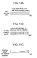
FIGS. 14A-D depict various control signals and a schematic for an alternative embodiment of the control circuitry for use in the manufacture of a deflectable catheter in accordance with the present invention. -
FIGS. 1A-C depict a planar view of an embodiment of a deflectable catheter in accordance with the present invention. As shown inFIG. 1B , apreferred catheter 100 comprises an elongated tubular catheter body having aproximal section 32, adistal tip section 34 and acontrol handle 36 at the proximal end of theproximal section 32.Tip electrode 38 andoptional ring electrode 40 are placed at or near deflectabledistal tip section 34 so as to provide a source of ablation energy if the desired device is an RF ablation catheter or for receiving electrical signals if the catheter is a diagnostic EP mapping catheter. Control handle 36 may be one of many designs capable of placing a pulling force on puller wires used to deflect thedeflectable tip section 34. Preferably, control handle 36 is the handle used in the Biosense EZ-Steer bidirectional family of products which control handle is depicted inFIGS. 1A-C . The "rocker"type lever 37 pulls one of two puller wires to deflect the catheter tip in one direction (FIG. 1A ) then can alternatively select the second (opposite) puller wire to deflect the catheter tip in the other direction (FIG. 1C ). The control handle 36 also had an adjustablefriction control knob 37a shown inFIG. 1D that allows the operator to use therocker lever 37 in a free state or to adjust the tension to lock therocker level 37 and the deflected tip in place. The amount of friction in the movement of therocker lever 37 increases as thefriction control knob 37a is rotated clockwise until it reaches the fully locked position. -
FIG. 2 depicts a cross-sectional view of the transition fromproximal section 32 anddeflectable section 34 ofcatheter 100 taken perpendicular to thecenter strut 80 that forms a portion of the catheter andFIG. 3 depicts the cross-section of the catheter ofFIG. 2 through line A-A.Catheter 100 comprises an elongated tubular construction having acentral lumen 58 through thedistal portion 32 and two half-cylindrical lumens 58a and58b in thedeflectable tip portion 34. Theproximal section 32 is flexible but substantially non-compressible along its length.Proximal section 32 can be made of any suitable construction and made of any suitable material. The preferred construction comprises anouter wall 30 made of Pellethane or PEBAX and an optionalinner wall 18. Theouter wall 30 may also comprise an imbedded braided mesh of stainless steel or similar material to increase torsional stiffness so that when control handle 36 is rotated the distal send ofproximal section 32 as well as thedistal section 34 will rotate in a corresponding manner. - The overall length of the length of the catheter will vary according to its application for use but a preferred length is between approximately 90 and 120 cm and more preferably between approximately 100 and 110 cm. The outer diameter of the
proximal section 32 is also a design characteristic that varies according to the application of the catheter but is preferably less than approximately 8 French (Fr). Optionalinner wall 18 comprises a polymeric tube which may optionally be spirally-sliced and is sized so that the outer diameter is about the same size or slightly smaller than the inner diameter ofouter wall 30 thereby providing additional stiffness which can be controlled by the pitch angle of the spiral slice. - In the embodiment shown, the
distal section 34 and theproximal section 32 are separate structures that have been fixedly attached to each other.Proximal section 32 anddistal section 34 may be attached using a polyurethane adhesive at the joint 35 between the two sections. Other means of attachment include joining the proximal and distal sections using heat to fuse the sections together. - In the EP catheter of the present invention,
tip electrode 38 andoptional ring electrodes 40 shown inFIGS. 1A-1C are each electrically connected to one of the bundle oflead wires 70. Each wire in the bundle oflead wire 70 extends from the control handle 36 through thelumen 58 in theproximal section 32 and through one oflumens distal section 34 to tipelectrode 38 and optional ring electrode (or electrodes) 40. The proximal end of eachlead wire 70 is connected to an appropriate connector (not shown) in the control handle 36 which can be connected to a suitable source of RF energy or to an EP mapping or other diagnostic or therapeutic system. -
Irrigation lumen 90 provides a conduit for transporting fluid from the proximal end of the catheter to thedistal tip portion 34.Irrigation lumen 90 is in fluid communication with one or more fluid ports in thetip electrode 38.FIGS. 4 and5 depict on possible arrangement ofirrigation fluid ports 439 in a tip electrode.Irrigation lumen 90 is used to transport an irrigation fluid through the catheter and out through the fluid ports in the tip in order to reduce coagulation of bodily fluids such as blood at or near the tip electrode. - In a bi-directional catheter a pair of
puller wires lumen 58 in theproximal section 32 and each extend through one oflumens distal section 34. The puller wires are made of any suitable material such as stainless steel or Nitinol wire or a non-metallic yarn such as Vectran® material. Preferably, each puller wire 44 is covered with a lubricious coating such as PTFE or a similar material. Each puller wire 44 extends from the control handle 36 to near the tip ofdistal section 34. - A sleeve or sleeves (not shown) may be used to house the puller wires proximally to the soft tip of the catheter. The sleeve is used to keep each puller wire on its respective sides of the center strut. For bi-directional deflection the opposing puller wires will always be placed in a separate lumen. With this design placing multiple puller wires in one lumen would be used for achieving different deflection curves in one deflection direction. Such a sleeve may be made of any suitable material, e.g., polyamide or polyimide.
- Examples of other suitable control handles 36 that can be used with the present invention are described in United States Patent No.
6,123,699 ,6,171,277 ,6,183,463 and6,198,974 the disclosures of which are hereby incorporated by reference. In such control handles proximal movement of the thumb control relative to the handle housing results in proximal movement of the first piston and first puller wire relative to the handle housing and catheter body, which results in deflection of the tip section in the direction of the lumen into which the first puller wire extends. Distal movement of the thumb control relative to the handle housing results in distal movement of the first piston, causing proximal movement of the second piston and puller wire relative to the handle housing and catheter body, which results in deflection of the tip section in the direction of the lumen into which the second puller wire extends. Additional configurations of puller wires 44 and gearing within the control handle may be used such as those disclosed in United States Patent No.7,077,823 which is also hereby incorporated by reference. - The
distal section 34 is comprised of aninner layer 62,braid layer 64 andouter layer 66 of the distal tip section described in greater detail below with respect to the method of manufacturing the catheter of the present invention discussed below with reference toFIG. 12 . - Additionally, a
safety wire 95 may be used to secure the tip electrode to the catheter shaft so as to prevent detachment of the tip electrode. The safety wire is preferably a 0.0065 inch diameter monel which is routed through thelumen 58 in theproximal portion 32 of the catheter as well as through one of the twolumens distal tip portion 34. The distal end of the safety wire is attached to thetip electrode 38 while the proximal portion is attached to an anchor point inside the control handle 36. -
FIG. 4 depicts an exploded view of the distal tip of a deflectable catheter in accordance with the present invention.FIG. 5 is a perspective view oftip electrode 438.Tip electrode 438 depicted inFIGS. 4 and5 is a machined metallic electrode comprised of a metal that is non-reactive in bodily fluid such as of gold, platinum, palladium or an alloy thereof.Tip electrode 438 may also be made of a first metal such as copper, silver, gold, aluminum, beryllium, bronze, palladium or alloys thereof which is then plated either internally and/or externally with a non-reactive metal such as gold, platinum, palladium or an alloy thereof.Tip electrode 438 may include a plurality ofirrigation ports 439 connected to acentral irrigation lumen 440 although such ports and lumens are optional. The proximal end oftip electrode 438 comprises a base 437 having a smaller diameter than the remainder of the tip electrode and adapted to fitcoupling 442.Base 437 may include a plurality ofserrations 437a that improve the bonding oftip electrode 438 intocoupling 442.Base 437 of thetip electrode 438 is heat bonded or ultrasonically welded to thecoupling 442.Tip dome 438a may be machined to provide a rounded atraumatic distal tip in order to reduce tissue damage during placement and/or use of the catheter.Lumen 495 provides a passageway forsafety wire 95 andlumen 470 provides a passageway forlead wire 70 that provide energy to thetip electrode 438.Lead wire 70 is attached to tipelectrode 438 using an electrically conductive solder or epoxy. - Injection molded
coupling 442 depicted inFIGS. 4 and6 has adistal section 443 with an internal diameter at its distal end adapted to receive thebase 437 oftip electrode 438 and has aproximal section 441 with aslot 441a adapted to receive thedistal end 480 of thecenter strut 80. Coupling 442 is injection molded from a medical grade polymer such as PEEK, ABS or Polycarbonate or other appropriate material known to one skilled in the art.Distal end 480 ofcenter strut 80 also includes a snap-fit notch 481 adapted to lock over snap-fit wedge 441b in thecoupling 442 thereby providing a mechanism for the quick assembly of the distal section of the deflectable catheter which method is described in greater detail below. Pullerwire anchor holes puller wires FIG. 7A .Puller wires epoxy 444c attached to its distal end. The Vectran® wire should be cleaned with alcohol and/or an ultrasonic bath before application of a ball of epoxy that is then cured under ultraviolet light. It is important that the epoxy be well fixed to the distal end of thepuller wires - A single puller wire 44, made of a non-metallic yarn such as Vectran® material, may be attached to the distal end of the catheter by threading the puller wire through one or
more anchor holes 82a-e incenter strut 80 so that the opposing ends of the puller wire, 44a and 44b, reside on opposing sides of the center strut as depicted inFIG. 8 . Such anchor holes 82a-e incenter strut 80 preferably have a diameter of 0.015 inch and are spaced apart by approximately 0.078 inch. Such anchor holes may be placed in thecenter strut 80 by laser cutting, punching and drilling. The number of holes on the strut, and the placement of the puller wires in one ormore anchor holes 82a-e will alter the curve shape and allow for both symmetric and asymmetric curve designs. For creating a symmetric curve the opposing ends of the puller wires would exit the same anchor hole towards opposing sides of the strut. Means for changing curve shape can be controlled by the distance between anchor holes used for the opposing ends of the puller wire. When the end of each of thepull wires center strut 80, pullingpull wire catheter 100 to deflect in-plane in the direction of the off-axis lumen in which the respective puller wire extends. - An alternate embodiment (not shown) uses two puller wires with metallic ferrules or plastic slugs to constrain the puller wires in their respective anchor hole located in the center strut. The puller wire would be threaded through the center strut on one side using the ferrule as a constraint from pulling completely through the anchor hole. An additional method for anchoring the puller wires is soldering, welding or using an adhesive to attach them to the center strut.
- Alternatively, the puller wires do not need to be attached to the center strut. A puller wire or puller wires could be attached to the tip dome or the distal end of the catheter's soft deflectable tip section.
FIGS. 9-11 show multiple configurations oftip electrodes 38 that are adapted to receive a single puller wire 44. The single puller wire 44 connected to thetip electrode 38 provides bi-directional control. To achieve this, a single puller wire is threaded through the dome electrode with the opposite sides of the puller wire residing on opposite sides of the center strut. Deflection direction will correspond with the path of least resistance. Moreover, individually manipulating a puller wire will result in in-plane deflection in the direction of the off-axis lumen in which the respective puller wire extends. Such embodiment directly supports symmetric curve designs. -
FIGS. 10 and11 depicthollow tip electrodes 38 that are adapted to receive aplug 45 which is force fit into the hollow dome. Puller wire 44 is threaded through the plug. One or more puller wires may be anchored in this manner. The puller wire is constrained in place once the plug is appropriately placed in the tip electrode. -
FIG. 7B depicts another embodiment of the distal tip section of thecatheter 100 where the puller wires are attached to the side wall of thedistal tip section 34 ofcatheter 100. Asmall hole 71 is drilled through theinner layer 62,braid layer 64 andouter layer 66 of the distal tip section. After thehole 71 is drilled, a grinder is used to lightly reduce the outer profile around the hole by removing approximately length=.04" depth=.013" of material. A stainless steelpuller wire bar 72 is attached to the distal end of the puller wire 44 via crimping to a ferrule or other means of adhesion. When the puller wire 44 is brought through the anchor window the bar rests on the outer profile of the thermoplastic soft deflectable tip section. Polyurethane is used to pot over thepuller wire bar 72 thereby rebuilding the original profile of thedistal tip section 34. In this manner each puller wire may be anchored to the outer periphery of thecatheter 100 at any location along the longitudinal axis of thedistal tip section 34. It is possible to anchor multiple puller wires in this manner, each on opposing sides of the center strut. Changing the location of the anchoring location changes the deflection profile of the catheter. - The proximal end of the
center strut 80 extends out of the proximal end of the soft deflectable tip portion. The proximal end of the center strut may be tapered so it can be readily placed within theproximal section 32 of the catheter helping to support the transition area. A sleeve preferably composed of PTFE may be placed over the tapered portion of the center strut constraining the puller wires and thereby preventing them from crossing. The sleeve is form fitting so it is tight around the center strut and wires but not so tight as to prevent the puller wires from readily moving in the longitudinal direction. -
FIG. 12 depicts a device for manufacturing the distal tip section of the present invention. Theinner layer 62 of thedistal section 34 of a catheter in accordance with the present invention is produced by extruding a thin layer of a thermoplastic elastomeric material, preferably between 0.0025-0.0035 inch in thickness, over an acetyl polymer mandrel of the appropriate diameter. Theinner layer 62 is then over-braided with a syntheticfiber braid layer 64 of approximately 0.002 to 0.003 inches in diameter. In a preferred embodiment the synthetic fiber is Pen monofilament from Biogeneral Advanced Fiber Technology. Next a second coat of elastomeric material is extruded over the braided inner layer to create theouter layer 66. Theinner layer 62 and theouter layer 66 may be made from elastomers having the same shore hardness or from materials having different shore hardnesses. Preferably, the elastomer is PEBAX or Pellethane due to processability and high heat deflection temperatures. - After the
outer layer 66 of elastomeric material is applied, the outside of theouter layer 66 is centerless ground to the desired finished outside diameter French size. The acetyl mandrel is removed and thecenter strut 80 is inserted through the center of theelastomeric tube 60. A half-moon elongated spacer made from a high temperature polymer such as PEEK, Teflon or liquid crystal polymer may be inserted into both sides of the inner diameter of theelastomeric tube 60 to stabilize and center thecenter strut 80 with respect to the center of the longitudinal axis of the elastomeric tube. This interim assembly is placed in the device depicted inFIG. 12 . -
Clamps center strut 80. Theclamps FIG. 12 are constructed from an electrically conductive material such as copper.Clamp 103b retracts and puts the strut under controlled tension using a pneumatic push-pull cylinder 104 or alternate automatically controlled tensioning means. The interim assembly is then nested and constrained in twofixtures Fixtures fixture adjustment mechanism Fixtures clamps center strut 80 thereby causing theinner layer 62 inner diameter to thermally bond with both thin longitudinal sides of thecenter strut 80 to define a composite structure with inseparable members. The strut temperature is monitored using atemperature feedback sensor 105, preferably a non-contact, fast response time thermopile based infrared sensor that senses the strut surface temperature. - One method for heating the center strut using the device shown in
Figure 12 uses the feedback controlled power circuit depicted inFIG. 13D . Aninfrared temperature sensor 510 monitors the temperature of theheated center strut 80 and provides an input voltage to a programmable logic controller (PLC) 520 analog to digital converter module. ThePLC 520 controls the analog switchingsolid state relay 530 with a built in synchronization circuit to control low-voltage, (5-28VAC) 50-60 hertz alternating current by varying the phase-angle to rapidly heat thecenter strut 80. The proportional, integral, and derivative (PID) loop temperature feedback control by the PLC enables the strut temperature to be monitored and the PLC adjusts the phase angle accordingly to achieve the correct temperature set point. The line voltage, AC load current and control input to the analog switchingsolid state relay 530 can be seen inFIGS. 13A-C respectively. The circuit is powered by 120VAC line voltage 501 controlled byswitch 502 and protected by 10amp fuse 503 which is stepped down usingtransformer 505 resulting in 12-24 V AC output. - An alternate method for closed loop heating of the center strut is shown in
FIGS.14A-D . In the schematic ofFIG. 14D for the heating power control circuitry, line voltage (120V AC) 601 controlled byswitch 602 and protected by 10amp fuse 603 is stepped down and converted into 12-24 V DC using step downtransformer 604 andbridge rectifier 605. A direct currentsolid state relay 630 is used to rapidly switch (on-off) 5-24 volt direct current using a time proportioning control PID loop algorithm that controls the mosfet or transistor output of theprogrammable logic controller 620 to the solid state relay control side. The control output pulse width and duration is dependent on the analog temperature measurement feedback from the thermopile basedinfrared sensor 610 to the PLC. - Once heating is completed, the tension is removed from the from the strut by translating
clamp 103a using the pneumatic push pull cylinder and the two halves offixture fixture adjustment mechanisms - The
distal tip section 34 with bonded center strut can then be affixed to theproximal section 32 as discussed above. Thetip electrode 34 is affixed to the distal end of thedistal tip section 34 and one of thelead wires 70 is attached to the electrode. A puller wire 44 orpuller wires irrigation lumen 90 is attached to the tip electrode and is routed through one of the two lumens. - One additional step in the manufacturing process is the roughening of side edges of the
center strut 80 to create abrasions of approximately 250-500 micro inches to improve adhesion to the inner diameter of the elastomeric tube - The preceding description has been presented with reference to presently preferred embodiments of the invention. Workers skilled in the art and technology to which this invention pertains will appreciate that alterations and changes in the described structure may be practiced without meaningfully departing from the principal, spirit and scope of this invention.
- Accordingly, the foregoing description should not be read as pertaining only to the precise structures described and illustrated in the accompanying drawings, but rather should be read consistent with and as support to the following claims which are to have their fullest and fair scope.
Claims (31)
- A catheter for use in a vessel comprising:an elongate tubular member having a proximal end and a distal end and having a first lumen disposed therein;a tip electrode disposed at the distal end of the tubular member;a center strut extending from near the proximal end of the tip electrode through a deflectable distal portion of the elongate tubular member and having a first longitudinal edge and a second longitudinal edge;wherein the center strut is bonded to the elongate tubular member substantially along entire length of the first longitudinal edge and the second longitudinal edge to create an inseparable composite structure from the center strut and the elongate tubular member.
- The catheter of claim 1 wherein the center strut has been thermally bonded to the elongate tubular member substantially along its entire length.
- The catheter of claim 1 further comprising a pull wire, having a proximal end and a distal end, for causing the deflectable distal portion of the elongate tubular member to deflect wherein the proximal end of the pull wire is attached to a control handle at the distal end of the catheter.
- The catheter of claim 3 wherein the distal end of the pull wire is attached to the tip electrode.
- The catheter of claim 1 further comprising a first pull wire and a second pull wire, each having a proximal end and a distal end, wherein the proximal end of the first and second pull wires are attached to a control handle and the distal end of the first pull wire is attached to a first face of the center strut and the distal end of the second pull wire is attached to the second face of the center strut.
- The catheter of claim 5 wherein the center strut comprises at least one anchor hole for attachment of the distal ends of the first and second pull wires.
- The catheter of claim 5 wherein the center strut comprises a plurality of anchor holes longitudinally spaced along the length of the center strut for attachment of the distal end of the first and second pull wires.
- The catheter of claim 7 wherein the plurality of anchor holes are spaced from adjacent anchor holes by approximately 0.078 inch.
- The catheter of claim 7 wherein the anchor holes are approximately 0.015 inch in diameter.
- The catheter of claim 1 further comprising a first pull wire and a second pull wire each having a proximal end and a distal end, wherein the proximal ends of the first and second pull wires are attached to a control handle and the distal ends of the first and second pull wires are attached to the tip electrode.
- The catheter of claim 10 wherein the tip electrode is comprised of a hollow portion and a plug and the distal ends of the first and second pull wires are attached to the plug prior to insertion in the hollow portion.
- The catheter of claim 1 further comprising a temperature sensor, or a location sensor.
- The catheter of claim 1 wherein the tip electrode has irrigation ports and the catheter further comprises an irrigation lumen in communication with the irrigation ports.
- The catheter of claim 1 further comprising a first pull wire and a second pull wire each having a proximal end and a distal end, wherein the proximal ends of the first and second pull wires are attached to a control handle and the distal ends of the first and second pull wires are attached to anchors and are threaded through first and second holes in the tubular member.
- The catheter of claim 1 wherein the tubular member has an inner layer, a braided layer and an outer layer and wherein the first longitudinal edge and the second longitudinal edge of the center strut is thermally bonded to the inner layer.
- The catheter of claim 1 wherein the center strut has been roughened along the first longitudinal edge and the second longitudinal edge to improve bonding with the tubular member.
- The catheter of claim 1 further comprising a molded coupling adapted to receive the proximal end portion of the tip electrode.
- The catheter of claim 17 wherein the molded coupling further comprises at least one slot adapted to receive at least one of the first or second longitudinal edges of the distal portion of the center strut.
- The catheter of claim 1 further comprising:a molded coupling having a distal portion adapted to receive a portion of the proximal end of the tip electrode and having a proximal portion having at least one slot adapted to receive at least one of the first or second longitudinal edges of the center strut.
- The catheter of either of claims 17 or 19 wherein the distal end of the center strut comprises at least one snap-fit notch and the molded coupling further comprises at least one snap-fit wedge adapted to receive the snap-fit notch.
- A method for manufacturing a distal tip for a deflectable catheter comprising the steps of:coating a cylindrical mandrel having a diameter with a first layer of thermoplastic material;covering the first layer of thermoplastic material with a braided layer;coating the braided layer with a second layer of thermoplastic material;removing the cylindrical mandrel thereby creating a tubular member;placing a strut having a width substantially similar to the diameter of the cylindrical mandrel, a length substantially greater than the width and a thickness substantially less than the width into the tubular member;disposing on each side of the strut half-cylindrical mandrels to create an interim assembly; and,heating the interim assembly in order to cause a thermal bonding between the first layer and the strut.
- The method of claim 21 wherein the method further comprises the step of roughening the strut along its thickness in order to promote bonding between the strut and the inner layer.
- The method of claim 21 wherein the method further comprises the steps of:placing the interim assembly in a fitting adapted to receive the interim assembly in order to limit localized heat distortion;placing electrically conductive clamps on each end of the strut; and,applying a current to the strut to heat the strut and the tubular member.
- The method of claim 21 wherein the step of heating the interim assembly further comprises the steps of monitoring the temperature of the strut and controlling the amount of current applied to the strut in response to the monitored temperature.
- The method of claim 21 further comprising the step of grinding the outer layer to the proper size.
- The method of claim 21 further comprising the step of removing the two half-cylindrical mandrels after completion of the heating step.
- The method of claim 26 further comprising the step of drilling one or more holes through the tubular member to provide anchor holes.
- The method of claim 24 further comprising the step of affixing a tip electrode to the distal end of the tubular member.
- The method of claim 24 further comprising the step of affixing at least one puller wire to at least one face of the strut.
- The method of claim 24 wherein the step of controlling the amount of current applied to the strut uses a programmable logic controller to control analog solid state switching relay to adjust the temperature of the strut based on input from a temperature monitor.
- The method of claim 24 wherein the step of controlling the amount of current applied to the strut uses a programmable logic controller to control the pulse width and duration of the output of a direct current solid state relay to adjust the temperature of the strut based on input from a temperature monitor.
Applications Claiming Priority (1)
| Application Number | Priority Date | Filing Date | Title |
|---|---|---|---|
| US12/207,130 US8118775B2 (en) | 2008-09-09 | 2008-09-09 | Deflectable catheter with bonded center strut and method of manufacture for same |
Publications (3)
| Publication Number | Publication Date |
|---|---|
| EP2172241A2 true EP2172241A2 (en) | 2010-04-07 |
| EP2172241A3 EP2172241A3 (en) | 2010-06-30 |
| EP2172241B1 EP2172241B1 (en) | 2012-12-26 |
Family
ID=41667543
Family Applications (1)
| Application Number | Title | Priority Date | Filing Date |
|---|---|---|---|
| EP09252148A Active EP2172241B1 (en) | 2008-09-09 | 2009-09-08 | Deflectable catheter with bonded center strut |
Country Status (10)
| Country | Link |
|---|---|
| US (2) | US8118775B2 (en) |
| EP (1) | EP2172241B1 (en) |
| JP (1) | JP5666112B2 (en) |
| CN (1) | CN101683285A (en) |
| AU (1) | AU2009212971B2 (en) |
| CA (1) | CA2678217C (en) |
| DK (1) | DK2172241T3 (en) |
| ES (1) | ES2401840T3 (en) |
| IL (2) | IL200750A (en) |
| RU (2) | RU2563384C1 (en) |
Cited By (5)
| Publication number | Priority date | Publication date | Assignee | Title |
|---|---|---|---|---|
| EP2604174A1 (en) * | 2011-12-15 | 2013-06-19 | Biosense Webster (Israel), Ltd. | Self-holding medical device control handle with cam actuated clutch mechanism |
| EP2752218A1 (en) * | 2013-01-07 | 2014-07-09 | Biosense Webster (Israel), Ltd. | Unidirectional catheter control handle with tensioning control |
| EP2817055A1 (en) * | 2012-02-25 | 2014-12-31 | Smiths Medical International Limited | Medico-surgical assemblies |
| EP3673944A1 (en) * | 2018-12-29 | 2020-07-01 | Biosense Webster (Israel) Ltd. | Improvements to puller wire t-bar for medical catheter |
| WO2021011537A1 (en) * | 2019-07-15 | 2021-01-21 | Medtronic, Inc. | Catheter with distal and proximal fixation members |
Families Citing this family (31)
| Publication number | Priority date | Publication date | Assignee | Title |
|---|---|---|---|---|
| US8808345B2 (en) * | 2008-12-31 | 2014-08-19 | Medtronic Ardian Luxembourg S.A.R.L. | Handle assemblies for intravascular treatment devices and associated systems and methods |
| JP4679668B1 (en) * | 2010-04-21 | 2011-04-27 | 日本ライフライン株式会社 | catheter |
| US8792962B2 (en) | 2010-12-30 | 2014-07-29 | Biosense Webster, Inc. | Catheter with single axial sensors |
| JP5875175B2 (en) * | 2011-10-21 | 2016-03-02 | 日本ライフライン株式会社 | Electrode catheter |
| WO2013077571A1 (en) * | 2011-11-23 | 2013-05-30 | 주식회사 리브스메드 | Surgical instrument |
| CN107031037B (en) | 2012-01-24 | 2020-12-01 | 史密夫和内修有限公司 | Porous structure and method for manufacturing same |
| JP5258005B1 (en) * | 2012-03-28 | 2013-08-07 | 日本ライフライン株式会社 | Electrode catheter |
| US10092905B2 (en) | 2012-06-22 | 2018-10-09 | Leica Biosystems Nussloch Gmbh | Tissue sample container and methods |
| EP2864467B1 (en) | 2012-06-22 | 2019-04-03 | Leica Biosystems Nussloch GmbH | Biopsy tissue sample transport device |
| US9549666B2 (en) | 2012-11-10 | 2017-01-24 | Curvo Medical, Inc. | Coaxial micro-endoscope |
| US9233225B2 (en) | 2012-11-10 | 2016-01-12 | Curvo Medical, Inc. | Coaxial bi-directional catheter |
| US9694161B2 (en) * | 2012-11-14 | 2017-07-04 | Biosense Webster (Israel), Ltd. | Catheter with flat beam providing nonsymmetrical curve bi-directional deflection |
| US9278187B2 (en) * | 2013-03-13 | 2016-03-08 | Biosense Webster (Israel) Ltd. | Method for making a low OHMIC pressure-contact electrical connection between split ring electrode and lead wire |
| US9806627B2 (en) | 2013-07-02 | 2017-10-31 | St. Jude Medical, Atrial Fibrillation Division, Inc. | System including power supply and power converter for providing AC power to medical devices |
| JP6071852B2 (en) * | 2013-11-25 | 2017-02-01 | 日本ライフライン株式会社 | Tip deflectable catheter |
| WO2015099935A1 (en) | 2013-12-24 | 2015-07-02 | St. Jude Medical, Cardiology Division, Inc. | Deflectable catheter bodies with corrugated structures |
| ES2921876T3 (en) * | 2015-01-09 | 2022-09-01 | Becton Dickinson & Co Ltd | infusion adapter |
| US10849521B2 (en) * | 2015-12-23 | 2020-12-01 | Biosense Webster (Israel) Ltd. | Multi-layered catheter shaft construction with embedded single axial sensors, and related methods |
| US10806629B2 (en) * | 2016-06-17 | 2020-10-20 | Gyroscope Therapeutics Limited | Injection device for subretinal delivery of therapeutic agent |
| US11103304B2 (en) * | 2017-06-13 | 2021-08-31 | Biosense Webster (Israel) Ltd. | Catheter with composite insert support member |
| RU2669483C1 (en) * | 2017-06-26 | 2018-10-11 | Федеральное государственное бюджетное образовательное учреждение высшего образования "Санкт-Петербургский государственный педиатрический медицинский университет" Министерства здравоохранения Российской Федерации (ФГБОУ ВО СПбГПМУ Минздрава России) | Device for passage of gastrotomy tube |
| EP3461526A1 (en) * | 2017-09-28 | 2019-04-03 | Koninklijke Philips N.V. | Invasive medical device and manufacturing method |
| CN108283757B (en) * | 2018-01-19 | 2020-11-13 | 武汉联影智融医疗科技有限公司 | Interventional catheter, guiding head of interventional catheter, interventional system and interventional method |
| CN110160676B (en) * | 2018-02-11 | 2021-10-26 | 上海微创电生理医疗科技股份有限公司 | Pressure sensor and electrophysiology catheter thereof |
| WO2021007542A1 (en) * | 2019-07-10 | 2021-01-14 | Vascular Technology, Incorporated | Graspable surgical device |
| US11524139B2 (en) | 2019-07-15 | 2022-12-13 | Medtronic, Inc. | Catheter with active return curve |
| JP6789559B1 (en) * | 2020-02-12 | 2020-11-25 | リバーフィールド株式会社 | Insulated shaft and high frequency forceps |
| JP7398293B2 (en) * | 2020-02-13 | 2023-12-14 | 日本発條株式会社 | Endoscope insert and endoscope using the same |
| CN116490239A (en) | 2020-11-09 | 2023-07-25 | 敏捷设备有限公司 | Device for steering a catheter |
| CN112882379B (en) * | 2021-01-13 | 2022-09-30 | 哈尔滨工业大学 | Airplane longitudinal gravity center allocation control method |
| CN117426807B (en) * | 2023-12-18 | 2024-03-12 | 中国医学科学院北京协和医院 | Vascular infrared positioning system used in laparoscopic surgery |
Citations (7)
| Publication number | Priority date | Publication date | Assignee | Title |
|---|---|---|---|---|
| USRE34502E (en) | 1988-11-18 | 1994-01-11 | Webster, Jr.; Wilton W. | Steerable catheter |
| US5531686A (en) | 1990-02-02 | 1996-07-02 | Ep Technologies, Inc. | Catheter steering mechanism |
| US6066125A (en) | 1997-09-05 | 2000-05-23 | Cordis Webster, Inc. | Omni-directional steerable catheter |
| US6171277B1 (en) | 1997-12-01 | 2001-01-09 | Cordis Webster, Inc. | Bi-directional control handle for steerable catheter |
| US6183463B1 (en) | 1997-12-01 | 2001-02-06 | Cordis Webster, Inc. | Bidirectional steerable cathether with bidirectional control handle |
| US6198974B1 (en) | 1998-08-14 | 2001-03-06 | Cordis Webster, Inc. | Bi-directional steerable catheter |
| US7077823B2 (en) | 2003-11-19 | 2006-07-18 | Biosense Webster, Inc. | Bidirectional steerable catheter with slidable mated puller wires |
Family Cites Families (19)
| Publication number | Priority date | Publication date | Assignee | Title |
|---|---|---|---|---|
| SU1655512A1 (en) * | 1987-11-25 | 1991-06-15 | И.А.Курдюков | Device for executing catheterization |
| EP0513224B1 (en) * | 1990-02-02 | 1996-10-23 | Ep Technologies, Inc. | Catheter steering mechanism |
| US5273535A (en) * | 1991-11-08 | 1993-12-28 | Ep Technologies, Inc. | Catheter with electrode tip having asymmetric left and right curve configurations |
| CA2013877C (en) * | 1990-04-04 | 2000-09-19 | Geoffrey S. Martin | Pre-curved dual lumen catheter |
| US5782828A (en) * | 1996-12-11 | 1998-07-21 | Irvine Biomedical, Inc. | Ablation catheter with multiple flexible curves |
| US6890329B2 (en) * | 1999-06-15 | 2005-05-10 | Cryocath Technologies Inc. | Defined deflection structure |
| US6829497B2 (en) * | 1999-09-21 | 2004-12-07 | Jamil Mogul | Steerable diagnostic catheters |
| US6172499B1 (en) | 1999-10-29 | 2001-01-09 | Ascension Technology Corporation | Eddy current error-reduced AC magnetic position measurement system |
| US6500144B1 (en) * | 2000-09-15 | 2002-12-31 | Scimed Life Systems, Inc. | Steerable catheter and self-mounting center support for use with same |
| US6605086B2 (en) * | 2001-05-02 | 2003-08-12 | Cardiac Pacemakers, Inc. | Steerable catheter with torque transfer system |
| US6585718B2 (en) * | 2001-05-02 | 2003-07-01 | Cardiac Pacemakers, Inc. | Steerable catheter with shaft support system for resisting axial compressive loads |
| US20030187389A1 (en) | 2002-03-29 | 2003-10-02 | Scimed Life Systems, Inc. | Center support for steerable electrophysiology catheter |
| IL165314A (en) | 2004-11-21 | 2009-08-03 | Elbit Ltd | Electromagnetic tracker |
| US7959601B2 (en) * | 2005-02-14 | 2011-06-14 | Biosense Webster, Inc. | Steerable catheter with in-plane deflection |
| JP4396983B2 (en) * | 2005-05-26 | 2010-01-13 | 日本ライフライン株式会社 | Thermal / heating treatment equipment |
| US8986298B2 (en) * | 2006-11-17 | 2015-03-24 | Biosense Webster, Inc. | Catheter with omni-directional optical tip having isolated optical paths |
| CN200984816Y (en) * | 2006-12-06 | 2007-12-05 | 汕头市盟星包装机械厂 | Temperature controlling device for heating system of plastic sheet material heat forming machine |
| US7985215B2 (en) | 2007-12-28 | 2011-07-26 | St. Jude Medical, Atrial Fibrillation Division, Inc. | Deflectable catheter with distal deflectable segment |
| US9101734B2 (en) * | 2008-09-09 | 2015-08-11 | Biosense Webster, Inc. | Force-sensing catheter with bonded center strut |
-
2008
- 2008-09-09 US US12/207,130 patent/US8118775B2/en active Active
-
2009
- 2009-09-06 IL IL200750A patent/IL200750A/en active IP Right Grant
- 2009-09-06 IL IL221383A patent/IL221383A/en active IP Right Grant
- 2009-09-07 AU AU2009212971A patent/AU2009212971B2/en not_active Ceased
- 2009-09-08 DK DK09252148.3T patent/DK2172241T3/en active
- 2009-09-08 ES ES09252148T patent/ES2401840T3/en active Active
- 2009-09-08 JP JP2009206700A patent/JP5666112B2/en active Active
- 2009-09-08 EP EP09252148A patent/EP2172241B1/en active Active
- 2009-09-08 CA CA2678217A patent/CA2678217C/en not_active Expired - Fee Related
- 2009-09-08 RU RU2013154769/14A patent/RU2563384C1/en not_active IP Right Cessation
- 2009-09-08 RU RU2009133734/14A patent/RU2519371C2/en not_active IP Right Cessation
- 2009-09-09 CN CN200910205773A patent/CN101683285A/en active Pending
-
2012
- 2012-01-17 US US13/351,371 patent/US8529505B2/en active Active
Patent Citations (8)
| Publication number | Priority date | Publication date | Assignee | Title |
|---|---|---|---|---|
| USRE34502E (en) | 1988-11-18 | 1994-01-11 | Webster, Jr.; Wilton W. | Steerable catheter |
| US5531686A (en) | 1990-02-02 | 1996-07-02 | Ep Technologies, Inc. | Catheter steering mechanism |
| US6066125A (en) | 1997-09-05 | 2000-05-23 | Cordis Webster, Inc. | Omni-directional steerable catheter |
| US6123699A (en) | 1997-09-05 | 2000-09-26 | Cordis Webster, Inc. | Omni-directional steerable catheter |
| US6171277B1 (en) | 1997-12-01 | 2001-01-09 | Cordis Webster, Inc. | Bi-directional control handle for steerable catheter |
| US6183463B1 (en) | 1997-12-01 | 2001-02-06 | Cordis Webster, Inc. | Bidirectional steerable cathether with bidirectional control handle |
| US6198974B1 (en) | 1998-08-14 | 2001-03-06 | Cordis Webster, Inc. | Bi-directional steerable catheter |
| US7077823B2 (en) | 2003-11-19 | 2006-07-18 | Biosense Webster, Inc. | Bidirectional steerable catheter with slidable mated puller wires |
Cited By (18)
| Publication number | Priority date | Publication date | Assignee | Title |
|---|---|---|---|---|
| US10293138B2 (en) | 2011-12-15 | 2019-05-21 | Biosense Webster (Israel) Ltd. | Self-holding medical device control handle with cam actuated clutch mechanism |
| US11491311B2 (en) | 2011-12-15 | 2022-11-08 | Biosense Webster (Israel) Ltd. | Self-holding medical device control handle with cam actuated clutch mechanism |
| US9101269B2 (en) | 2011-12-15 | 2015-08-11 | Biosense Webster (Israel), Ltd. | Self-holding medical device control handle with cam actuated clutch mechanism |
| EP2604174A1 (en) * | 2011-12-15 | 2013-06-19 | Biosense Webster (Israel), Ltd. | Self-holding medical device control handle with cam actuated clutch mechanism |
| EP2817055A1 (en) * | 2012-02-25 | 2014-12-31 | Smiths Medical International Limited | Medico-surgical assemblies |
| US9174023B2 (en) | 2013-01-07 | 2015-11-03 | Biosense Webster (Israel) Ltd. | Unidirectional catheter control handle with tensioning control |
| EP3124069A3 (en) * | 2013-01-07 | 2017-05-10 | Biosense Webster (Israel) Ltd. | Unidirectional catheter control handle with tensioning control |
| AU2013273702B2 (en) * | 2013-01-07 | 2017-11-02 | Biosense Webster (Israel) Ltd. | Unidirectional catheter control handle with tensioning control |
| US9545499B2 (en) | 2013-01-07 | 2017-01-17 | Biosense Webster (Israel) Ltd. | Unidirectional catheter control handle with tensioning control |
| US10632286B2 (en) | 2013-01-07 | 2020-04-28 | Biosense Webster (Israel) Ltd. | Unidirectional catheter control handle with tensioning control |
| US11446471B2 (en) | 2013-01-07 | 2022-09-20 | Biosense Webster (Israel) Ltd. | Unidirectional catheter control handle with tensioning control |
| EP2752218A1 (en) * | 2013-01-07 | 2014-07-09 | Biosense Webster (Israel), Ltd. | Unidirectional catheter control handle with tensioning control |
| US11744995B2 (en) | 2013-01-07 | 2023-09-05 | Biosense Webster (Israel) Ltd. | Unidirectional catheter control handle with tensioning control |
| EP3673944A1 (en) * | 2018-12-29 | 2020-07-01 | Biosense Webster (Israel) Ltd. | Improvements to puller wire t-bar for medical catheter |
| US11517716B2 (en) | 2018-12-29 | 2022-12-06 | Biosense Webster (Israel) Ltd. | Puller wire t-bar for medical catheter |
| US20230083615A1 (en) * | 2018-12-29 | 2023-03-16 | Biosense Webster (Israel) Ltd. | Puller wire t-bar for medical catheter |
| US11717648B2 (en) | 2018-12-29 | 2023-08-08 | Biosense Webster (Israel) Ltd. | Puller wire t-bar for medical catheter |
| WO2021011537A1 (en) * | 2019-07-15 | 2021-01-21 | Medtronic, Inc. | Catheter with distal and proximal fixation members |
Also Published As
| Publication number | Publication date |
|---|---|
| RU2519371C2 (en) | 2014-06-10 |
| EP2172241B1 (en) | 2012-12-26 |
| CA2678217A1 (en) | 2010-03-09 |
| RU2563384C1 (en) | 2015-09-20 |
| US20100063441A1 (en) | 2010-03-11 |
| RU2009133734A (en) | 2011-03-20 |
| IL200750A0 (en) | 2010-05-17 |
| AU2009212971A1 (en) | 2010-03-25 |
| CN101683285A (en) | 2010-03-31 |
| ES2401840T3 (en) | 2013-04-24 |
| US8529505B2 (en) | 2013-09-10 |
| CA2678217C (en) | 2018-02-20 |
| JP5666112B2 (en) | 2015-02-12 |
| US8118775B2 (en) | 2012-02-21 |
| IL221383A (en) | 2014-02-27 |
| EP2172241A3 (en) | 2010-06-30 |
| AU2009212971B2 (en) | 2014-09-11 |
| DK2172241T3 (en) | 2013-04-02 |
| US20120111482A1 (en) | 2012-05-10 |
| RU2013154769A (en) | 2015-09-10 |
| JP2010063886A (en) | 2010-03-25 |
| IL200750A (en) | 2013-03-24 |
Similar Documents
| Publication | Publication Date | Title |
|---|---|---|
| CA2678217C (en) | Deflectable catheter with bonded center strut and method of manufacture for same | |
| US6569114B2 (en) | Steerable catheter with struts | |
| JP5989653B2 (en) | Steerable introducer sheath system | |
| US9433751B2 (en) | Steerable catheter with distal tip orientation sheaths | |
| US9089339B2 (en) | Electrophysiology catheter with improved tip electrode | |
| US20030195605A1 (en) | Cryogenic catheter with deflectable tip | |
| JP2004073832A (en) | Catheter with articulated system | |
| AU2002323328A1 (en) | Cryogenic catheter with deflectable tip | |
| US7322988B2 (en) | Methods of forming catheters with soft distal tips | |
| EP3124069B1 (en) | Unidirectional catheter control handle with tensioning control | |
| CN105193498B (en) | Ablation catheter apparatus | |
| AU2013203884B2 (en) | Deflectable catheter with bonded center strut and method of manufacture for same |
Legal Events
| Date | Code | Title | Description |
|---|---|---|---|
| PUAI | Public reference made under article 153(3) epc to a published international application that has entered the european phase |
Free format text: ORIGINAL CODE: 0009012 |
|
| AK | Designated contracting states |
Kind code of ref document: A2 Designated state(s): AT BE BG CH CY CZ DE DK EE ES FI FR GB GR HR HU IE IS IT LI LT LU LV MC MK MT NL NO PL PT RO SE SI SK SM TR |
|
| AX | Request for extension of the european patent |
Extension state: AL BA RS |
|
| PUAL | Search report despatched |
Free format text: ORIGINAL CODE: 0009013 |
|
| AK | Designated contracting states |
Kind code of ref document: A3 Designated state(s): AT BE BG CH CY CZ DE DK EE ES FI FR GB GR HR HU IE IS IT LI LT LU LV MC MK MT NL NO PL PT RO SE SI SK SM TR |
|
| AX | Request for extension of the european patent |
Extension state: AL BA RS |
|
| 17P | Request for examination filed |
Effective date: 20101222 |
|
| 17Q | First examination report despatched |
Effective date: 20110110 |
|
| REG | Reference to a national code |
Ref country code: DE Ref legal event code: R079 Ref document number: 602009012208 Country of ref document: DE Free format text: PREVIOUS MAIN CLASS: A61M0025010000 Ipc: A61M0025000000 |
|
| GRAP | Despatch of communication of intention to grant a patent |
Free format text: ORIGINAL CODE: EPIDOSNIGR1 |
|
| RIC1 | Information provided on ipc code assigned before grant |
Ipc: A61B 18/14 20060101ALI20120817BHEP Ipc: A61M 25/00 20060101AFI20120817BHEP Ipc: A61B 5/02 20060101ALI20120817BHEP Ipc: A61B 5/042 20060101ALI20120817BHEP Ipc: A61M 25/01 20060101ALI20120817BHEP |
|
| GRAS | Grant fee paid |
Free format text: ORIGINAL CODE: EPIDOSNIGR3 |
|
| GRAA | (expected) grant |
Free format text: ORIGINAL CODE: 0009210 |
|
| AK | Designated contracting states |
Kind code of ref document: B1 Designated state(s): AT BE BG CH CY CZ DE DK EE ES FI FR GB GR HR HU IE IS IT LI LT LU LV MC MK MT NL NO PL PT RO SE SI SK SM TR |
|
| REG | Reference to a national code |
Ref country code: GB Ref legal event code: FG4D |
|
| REG | Reference to a national code |
Ref country code: CH Ref legal event code: EP |
|
| REG | Reference to a national code |
Ref country code: AT Ref legal event code: REF Ref document number: 590115 Country of ref document: AT Kind code of ref document: T Effective date: 20130115 |
|
| REG | Reference to a national code |
Ref country code: DE Ref legal event code: R082 Ref document number: 602009012208 Country of ref document: DE Representative=s name: BOEHMERT & BOEHMERT, DE Ref country code: DE Ref legal event code: R082 Ref document number: 602009012208 Country of ref document: DE Representative=s name: BOEHMERT & BOEHMERT ANWALTSPARTNERSCHAFT MBB -, DE |
|
| RAP2 | Party data changed (patent owner data changed or rights of a patent transferred) |
Owner name: BIOSENSE WEBSTER, INC. |
|
| REG | Reference to a national code |
Ref country code: DE Ref legal event code: R096 Ref document number: 602009012208 Country of ref document: DE Effective date: 20130307 |
|
| REG | Reference to a national code |
Ref country code: NL Ref legal event code: TD Effective date: 20130314 |
|
| REG | Reference to a national code |
Ref country code: SE Ref legal event code: TRGR |
|
| REG | Reference to a national code |
Ref country code: NL Ref legal event code: T3 |
|
| REG | Reference to a national code |
Ref country code: DK Ref legal event code: T3 |
|
| REG | Reference to a national code |
Ref country code: ES Ref legal event code: FG2A Ref document number: 2401840 Country of ref document: ES Kind code of ref document: T3 Effective date: 20130424 |
|
| PG25 | Lapsed in a contracting state [announced via postgrant information from national office to epo] |
Ref country code: HR Free format text: LAPSE BECAUSE OF FAILURE TO SUBMIT A TRANSLATION OF THE DESCRIPTION OR TO PAY THE FEE WITHIN THE PRESCRIBED TIME-LIMIT Effective date: 20121226 Ref country code: NO Free format text: LAPSE BECAUSE OF FAILURE TO SUBMIT A TRANSLATION OF THE DESCRIPTION OR TO PAY THE FEE WITHIN THE PRESCRIBED TIME-LIMIT Effective date: 20130326 Ref country code: LT Free format text: LAPSE BECAUSE OF FAILURE TO SUBMIT A TRANSLATION OF THE DESCRIPTION OR TO PAY THE FEE WITHIN THE PRESCRIBED TIME-LIMIT Effective date: 20121226 |
|
| REG | Reference to a national code |
Ref country code: AT Ref legal event code: MK05 Ref document number: 590115 Country of ref document: AT Kind code of ref document: T Effective date: 20121226 |
|
| REG | Reference to a national code |
Ref country code: LT Ref legal event code: MG4D |
|
| PG25 | Lapsed in a contracting state [announced via postgrant information from national office to epo] |
Ref country code: LV Free format text: LAPSE BECAUSE OF FAILURE TO SUBMIT A TRANSLATION OF THE DESCRIPTION OR TO PAY THE FEE WITHIN THE PRESCRIBED TIME-LIMIT Effective date: 20121226 Ref country code: GR Free format text: LAPSE BECAUSE OF FAILURE TO SUBMIT A TRANSLATION OF THE DESCRIPTION OR TO PAY THE FEE WITHIN THE PRESCRIBED TIME-LIMIT Effective date: 20130327 Ref country code: SI Free format text: LAPSE BECAUSE OF FAILURE TO SUBMIT A TRANSLATION OF THE DESCRIPTION OR TO PAY THE FEE WITHIN THE PRESCRIBED TIME-LIMIT Effective date: 20121226 |
|
| REG | Reference to a national code |
Ref country code: GB Ref legal event code: S117 Free format text: REQUEST FILED; REQUEST FOR CORRECTION UNDER SECTION 117 FILED ON 18 FEBRUARY 2013 |
|
| REG | Reference to a national code |
Ref country code: GB Ref legal event code: S117 Free format text: REQUEST NOT PROCEEDED WITH; REQUEST FOR CORRECTION UNDER SECTION 117 FILED ON 18 FEBRUARY 2013 NOT PROCEEDED WITH ON 10 JUNE 2013 |
|
| PG25 | Lapsed in a contracting state [announced via postgrant information from national office to epo] |
Ref country code: SK Free format text: LAPSE BECAUSE OF FAILURE TO SUBMIT A TRANSLATION OF THE DESCRIPTION OR TO PAY THE FEE WITHIN THE PRESCRIBED TIME-LIMIT Effective date: 20121226 Ref country code: AT Free format text: LAPSE BECAUSE OF FAILURE TO SUBMIT A TRANSLATION OF THE DESCRIPTION OR TO PAY THE FEE WITHIN THE PRESCRIBED TIME-LIMIT Effective date: 20121226 Ref country code: IS Free format text: LAPSE BECAUSE OF FAILURE TO SUBMIT A TRANSLATION OF THE DESCRIPTION OR TO PAY THE FEE WITHIN THE PRESCRIBED TIME-LIMIT Effective date: 20130426 Ref country code: BG Free format text: LAPSE BECAUSE OF FAILURE TO SUBMIT A TRANSLATION OF THE DESCRIPTION OR TO PAY THE FEE WITHIN THE PRESCRIBED TIME-LIMIT Effective date: 20130326 Ref country code: EE Free format text: LAPSE BECAUSE OF FAILURE TO SUBMIT A TRANSLATION OF THE DESCRIPTION OR TO PAY THE FEE WITHIN THE PRESCRIBED TIME-LIMIT Effective date: 20121226 |
|
| PG25 | Lapsed in a contracting state [announced via postgrant information from national office to epo] |
Ref country code: PL Free format text: LAPSE BECAUSE OF FAILURE TO SUBMIT A TRANSLATION OF THE DESCRIPTION OR TO PAY THE FEE WITHIN THE PRESCRIBED TIME-LIMIT Effective date: 20121226 Ref country code: RO Free format text: LAPSE BECAUSE OF FAILURE TO SUBMIT A TRANSLATION OF THE DESCRIPTION OR TO PAY THE FEE WITHIN THE PRESCRIBED TIME-LIMIT Effective date: 20121226 Ref country code: PT Free format text: LAPSE BECAUSE OF FAILURE TO SUBMIT A TRANSLATION OF THE DESCRIPTION OR TO PAY THE FEE WITHIN THE PRESCRIBED TIME-LIMIT Effective date: 20130426 |
|
| PLBE | No opposition filed within time limit |
Free format text: ORIGINAL CODE: 0009261 |
|
| STAA | Information on the status of an ep patent application or granted ep patent |
Free format text: STATUS: NO OPPOSITION FILED WITHIN TIME LIMIT |
|
| PG25 | Lapsed in a contracting state [announced via postgrant information from national office to epo] |
Ref country code: CY Free format text: LAPSE BECAUSE OF FAILURE TO SUBMIT A TRANSLATION OF THE DESCRIPTION OR TO PAY THE FEE WITHIN THE PRESCRIBED TIME-LIMIT Effective date: 20121226 |
|
| 26N | No opposition filed |
Effective date: 20130927 |
|
| REG | Reference to a national code |
Ref country code: DE Ref legal event code: R097 Ref document number: 602009012208 Country of ref document: DE Effective date: 20130927 |
|
| PG25 | Lapsed in a contracting state [announced via postgrant information from national office to epo] |
Ref country code: MC Free format text: LAPSE BECAUSE OF FAILURE TO SUBMIT A TRANSLATION OF THE DESCRIPTION OR TO PAY THE FEE WITHIN THE PRESCRIBED TIME-LIMIT Effective date: 20121226 |
|
| PG25 | Lapsed in a contracting state [announced via postgrant information from national office to epo] |
Ref country code: SM Free format text: LAPSE BECAUSE OF FAILURE TO SUBMIT A TRANSLATION OF THE DESCRIPTION OR TO PAY THE FEE WITHIN THE PRESCRIBED TIME-LIMIT Effective date: 20121226 |
|
| PG25 | Lapsed in a contracting state [announced via postgrant information from national office to epo] |
Ref country code: TR Free format text: LAPSE BECAUSE OF FAILURE TO SUBMIT A TRANSLATION OF THE DESCRIPTION OR TO PAY THE FEE WITHIN THE PRESCRIBED TIME-LIMIT Effective date: 20121226 Ref country code: MT Free format text: LAPSE BECAUSE OF FAILURE TO SUBMIT A TRANSLATION OF THE DESCRIPTION OR TO PAY THE FEE WITHIN THE PRESCRIBED TIME-LIMIT Effective date: 20121226 |
|
| PG25 | Lapsed in a contracting state [announced via postgrant information from national office to epo] |
Ref country code: MK Free format text: LAPSE BECAUSE OF FAILURE TO SUBMIT A TRANSLATION OF THE DESCRIPTION OR TO PAY THE FEE WITHIN THE PRESCRIBED TIME-LIMIT Effective date: 20121226 Ref country code: HU Free format text: LAPSE BECAUSE OF FAILURE TO SUBMIT A TRANSLATION OF THE DESCRIPTION OR TO PAY THE FEE WITHIN THE PRESCRIBED TIME-LIMIT; INVALID AB INITIO Effective date: 20090908 Ref country code: LU Free format text: LAPSE BECAUSE OF NON-PAYMENT OF DUE FEES Effective date: 20130908 |
|
| REG | Reference to a national code |
Ref country code: FR Ref legal event code: PLFP Year of fee payment: 8 |
|
| REG | Reference to a national code |
Ref country code: FR Ref legal event code: PLFP Year of fee payment: 9 |
|
| REG | Reference to a national code |
Ref country code: FR Ref legal event code: PLFP Year of fee payment: 10 |
|
| PGFP | Annual fee paid to national office [announced via postgrant information from national office to epo] |
Ref country code: CZ Payment date: 20190826 Year of fee payment: 11 Ref country code: FI Payment date: 20190909 Year of fee payment: 11 Ref country code: IE Payment date: 20190910 Year of fee payment: 11 Ref country code: DK Payment date: 20190910 Year of fee payment: 11 Ref country code: SE Payment date: 20190910 Year of fee payment: 11 |
|
| PGFP | Annual fee paid to national office [announced via postgrant information from national office to epo] |
Ref country code: BE Payment date: 20190815 Year of fee payment: 11 |
|
| PGFP | Annual fee paid to national office [announced via postgrant information from national office to epo] |
Ref country code: CH Payment date: 20190913 Year of fee payment: 11 |
|
| PGFP | Annual fee paid to national office [announced via postgrant information from national office to epo] |
Ref country code: ES Payment date: 20191001 Year of fee payment: 11 |
|
| REG | Reference to a national code |
Ref country code: FI Ref legal event code: MAE |
|
| REG | Reference to a national code |
Ref country code: DK Ref legal event code: EBP Effective date: 20200930 |
|
| PG25 | Lapsed in a contracting state [announced via postgrant information from national office to epo] |
Ref country code: CZ Free format text: LAPSE BECAUSE OF NON-PAYMENT OF DUE FEES Effective date: 20200908 Ref country code: FI Free format text: LAPSE BECAUSE OF NON-PAYMENT OF DUE FEES Effective date: 20200908 |
|
| REG | Reference to a national code |
Ref country code: CH Ref legal event code: PL |
|
| REG | Reference to a national code |
Ref country code: BE Ref legal event code: MM Effective date: 20200930 |
|
| PG25 | Lapsed in a contracting state [announced via postgrant information from national office to epo] |
Ref country code: CH Free format text: LAPSE BECAUSE OF NON-PAYMENT OF DUE FEES Effective date: 20200930 Ref country code: BE Free format text: LAPSE BECAUSE OF NON-PAYMENT OF DUE FEES Effective date: 20200930 Ref country code: LI Free format text: LAPSE BECAUSE OF NON-PAYMENT OF DUE FEES Effective date: 20200930 Ref country code: IE Free format text: LAPSE BECAUSE OF NON-PAYMENT OF DUE FEES Effective date: 20200908 Ref country code: SE Free format text: LAPSE BECAUSE OF NON-PAYMENT OF DUE FEES Effective date: 20200909 |
|
| REG | Reference to a national code |
Ref country code: SE Ref legal event code: EUG |
|
| PG25 | Lapsed in a contracting state [announced via postgrant information from national office to epo] |
Ref country code: DK Free format text: LAPSE BECAUSE OF NON-PAYMENT OF DUE FEES Effective date: 20200930 |
|
| REG | Reference to a national code |
Ref country code: ES Ref legal event code: FD2A Effective date: 20220117 |
|
| PG25 | Lapsed in a contracting state [announced via postgrant information from national office to epo] |
Ref country code: ES Free format text: LAPSE BECAUSE OF NON-PAYMENT OF DUE FEES Effective date: 20200909 |
|
| PGFP | Annual fee paid to national office [announced via postgrant information from national office to epo] |
Ref country code: NL Payment date: 20220819 Year of fee payment: 14 |
|
| PGFP | Annual fee paid to national office [announced via postgrant information from national office to epo] |
Ref country code: IT Payment date: 20230810 Year of fee payment: 15 Ref country code: GB Payment date: 20230803 Year of fee payment: 15 |
|
| PGFP | Annual fee paid to national office [announced via postgrant information from national office to epo] |
Ref country code: FR Payment date: 20230808 Year of fee payment: 15 Ref country code: DE Payment date: 20230802 Year of fee payment: 15 |