EP2174608A1 - Bone anchoring device and stabilization device for bone parts or vertebrae - Google Patents
Bone anchoring device and stabilization device for bone parts or vertebrae Download PDFInfo
- Publication number
- EP2174608A1 EP2174608A1 EP08017644A EP08017644A EP2174608A1 EP 2174608 A1 EP2174608 A1 EP 2174608A1 EP 08017644 A EP08017644 A EP 08017644A EP 08017644 A EP08017644 A EP 08017644A EP 2174608 A1 EP2174608 A1 EP 2174608A1
- Authority
- EP
- European Patent Office
- Prior art keywords
- rods
- bone anchoring
- bone
- receiving part
- pressure element
- Prior art date
- Legal status (The legal status is an assumption and is not a legal conclusion. Google has not performed a legal analysis and makes no representation as to the accuracy of the status listed.)
- Granted
Links
Images

Classifications
-
- A—HUMAN NECESSITIES
- A61—MEDICAL OR VETERINARY SCIENCE; HYGIENE
- A61B—DIAGNOSIS; SURGERY; IDENTIFICATION
- A61B17/00—Surgical instruments, devices or methods, e.g. tourniquets
- A61B17/56—Surgical instruments or methods for treatment of bones or joints; Devices specially adapted therefor
- A61B17/58—Surgical instruments or methods for treatment of bones or joints; Devices specially adapted therefor for osteosynthesis, e.g. bone plates, screws, setting implements or the like
- A61B17/68—Internal fixation devices, including fasteners and spinal fixators, even if a part thereof projects from the skin
- A61B17/70—Spinal positioners or stabilisers ; Bone stabilisers comprising fluid filler in an implant
- A61B17/7001—Screws or hooks combined with longitudinal elements which do not contact vertebrae
- A61B17/7035—Screws or hooks, wherein a rod-clamping part and a bone-anchoring part can pivot relative to each other
-
- A—HUMAN NECESSITIES
- A61—MEDICAL OR VETERINARY SCIENCE; HYGIENE
- A61B—DIAGNOSIS; SURGERY; IDENTIFICATION
- A61B17/00—Surgical instruments, devices or methods, e.g. tourniquets
- A61B17/56—Surgical instruments or methods for treatment of bones or joints; Devices specially adapted therefor
- A61B17/58—Surgical instruments or methods for treatment of bones or joints; Devices specially adapted therefor for osteosynthesis, e.g. bone plates, screws, setting implements or the like
- A61B17/68—Internal fixation devices, including fasteners and spinal fixators, even if a part thereof projects from the skin
- A61B17/70—Spinal positioners or stabilisers ; Bone stabilisers comprising fluid filler in an implant
- A61B17/7001—Screws or hooks combined with longitudinal elements which do not contact vertebrae
- A61B17/7002—Longitudinal elements, e.g. rods
- A61B17/7004—Longitudinal elements, e.g. rods with a cross-section which varies along its length
- A61B17/7008—Longitudinal elements, e.g. rods with a cross-section which varies along its length with parts of, or attached to, the longitudinal elements, bearing against an outside of the screw or hook heads, e.g. nuts on threaded rods
-
- A—HUMAN NECESSITIES
- A61—MEDICAL OR VETERINARY SCIENCE; HYGIENE
- A61B—DIAGNOSIS; SURGERY; IDENTIFICATION
- A61B17/00—Surgical instruments, devices or methods, e.g. tourniquets
- A61B17/56—Surgical instruments or methods for treatment of bones or joints; Devices specially adapted therefor
- A61B17/58—Surgical instruments or methods for treatment of bones or joints; Devices specially adapted therefor for osteosynthesis, e.g. bone plates, screws, setting implements or the like
- A61B17/68—Internal fixation devices, including fasteners and spinal fixators, even if a part thereof projects from the skin
- A61B17/70—Spinal positioners or stabilisers ; Bone stabilisers comprising fluid filler in an implant
- A61B17/7001—Screws or hooks combined with longitudinal elements which do not contact vertebrae
- A61B17/7002—Longitudinal elements, e.g. rods
- A61B17/7019—Longitudinal elements having flexible parts, or parts connected together, such that after implantation the elements can move relative to each other
- A61B17/702—Longitudinal elements having flexible parts, or parts connected together, such that after implantation the elements can move relative to each other having a core or insert, and a sleeve, whereby a screw or hook can move along the core or in the sleeve
-
- A—HUMAN NECESSITIES
- A61—MEDICAL OR VETERINARY SCIENCE; HYGIENE
- A61B—DIAGNOSIS; SURGERY; IDENTIFICATION
- A61B17/00—Surgical instruments, devices or methods, e.g. tourniquets
- A61B17/56—Surgical instruments or methods for treatment of bones or joints; Devices specially adapted therefor
- A61B17/58—Surgical instruments or methods for treatment of bones or joints; Devices specially adapted therefor for osteosynthesis, e.g. bone plates, screws, setting implements or the like
- A61B17/68—Internal fixation devices, including fasteners and spinal fixators, even if a part thereof projects from the skin
- A61B17/70—Spinal positioners or stabilisers ; Bone stabilisers comprising fluid filler in an implant
- A61B17/7001—Screws or hooks combined with longitudinal elements which do not contact vertebrae
- A61B17/7002—Longitudinal elements, e.g. rods
- A61B17/7019—Longitudinal elements having flexible parts, or parts connected together, such that after implantation the elements can move relative to each other
- A61B17/7031—Longitudinal elements having flexible parts, or parts connected together, such that after implantation the elements can move relative to each other made wholly or partly of flexible material
-
- A—HUMAN NECESSITIES
- A61—MEDICAL OR VETERINARY SCIENCE; HYGIENE
- A61B—DIAGNOSIS; SURGERY; IDENTIFICATION
- A61B17/00—Surgical instruments, devices or methods, e.g. tourniquets
- A61B17/56—Surgical instruments or methods for treatment of bones or joints; Devices specially adapted therefor
- A61B17/58—Surgical instruments or methods for treatment of bones or joints; Devices specially adapted therefor for osteosynthesis, e.g. bone plates, screws, setting implements or the like
- A61B17/68—Internal fixation devices, including fasteners and spinal fixators, even if a part thereof projects from the skin
- A61B17/70—Spinal positioners or stabilisers ; Bone stabilisers comprising fluid filler in an implant
- A61B17/7001—Screws or hooks combined with longitudinal elements which do not contact vertebrae
- A61B17/7032—Screws or hooks with U-shaped head or back through which longitudinal rods pass
-
- A—HUMAN NECESSITIES
- A61—MEDICAL OR VETERINARY SCIENCE; HYGIENE
- A61B—DIAGNOSIS; SURGERY; IDENTIFICATION
- A61B17/00—Surgical instruments, devices or methods, e.g. tourniquets
- A61B17/56—Surgical instruments or methods for treatment of bones or joints; Devices specially adapted therefor
- A61B17/58—Surgical instruments or methods for treatment of bones or joints; Devices specially adapted therefor for osteosynthesis, e.g. bone plates, screws, setting implements or the like
- A61B17/68—Internal fixation devices, including fasteners and spinal fixators, even if a part thereof projects from the skin
- A61B17/70—Spinal positioners or stabilisers ; Bone stabilisers comprising fluid filler in an implant
- A61B17/7001—Screws or hooks combined with longitudinal elements which do not contact vertebrae
- A61B17/7035—Screws or hooks, wherein a rod-clamping part and a bone-anchoring part can pivot relative to each other
- A61B17/7037—Screws or hooks, wherein a rod-clamping part and a bone-anchoring part can pivot relative to each other wherein pivoting is blocked when the rod is clamped
-
- A—HUMAN NECESSITIES
- A61—MEDICAL OR VETERINARY SCIENCE; HYGIENE
- A61B—DIAGNOSIS; SURGERY; IDENTIFICATION
- A61B17/00—Surgical instruments, devices or methods, e.g. tourniquets
- A61B17/56—Surgical instruments or methods for treatment of bones or joints; Devices specially adapted therefor
- A61B17/58—Surgical instruments or methods for treatment of bones or joints; Devices specially adapted therefor for osteosynthesis, e.g. bone plates, screws, setting implements or the like
- A61B17/68—Internal fixation devices, including fasteners and spinal fixators, even if a part thereof projects from the skin
- A61B17/70—Spinal positioners or stabilisers ; Bone stabilisers comprising fluid filler in an implant
- A61B17/7001—Screws or hooks combined with longitudinal elements which do not contact vertebrae
- A61B17/7046—Screws or hooks combined with longitudinal elements which do not contact vertebrae the screws or hooks being mobile in use relative to the longitudinal element
-
- A—HUMAN NECESSITIES
- A61—MEDICAL OR VETERINARY SCIENCE; HYGIENE
- A61B—DIAGNOSIS; SURGERY; IDENTIFICATION
- A61B17/00—Surgical instruments, devices or methods, e.g. tourniquets
- A61B17/56—Surgical instruments or methods for treatment of bones or joints; Devices specially adapted therefor
- A61B17/58—Surgical instruments or methods for treatment of bones or joints; Devices specially adapted therefor for osteosynthesis, e.g. bone plates, screws, setting implements or the like
- A61B17/68—Internal fixation devices, including fasteners and spinal fixators, even if a part thereof projects from the skin
- A61B17/70—Spinal positioners or stabilisers ; Bone stabilisers comprising fluid filler in an implant
- A61B17/7049—Connectors, not bearing on the vertebrae, for linking longitudinal elements together
-
- A—HUMAN NECESSITIES
- A61—MEDICAL OR VETERINARY SCIENCE; HYGIENE
- A61B—DIAGNOSIS; SURGERY; IDENTIFICATION
- A61B17/00—Surgical instruments, devices or methods, e.g. tourniquets
- A61B2017/00831—Material properties
- A61B2017/0084—Material properties low friction
- A61B2017/00845—Material properties low friction of moving parts with respect to each other
Definitions
- the invention relates to a bone anchoring device, in particular to a polyaxial bone screw which is connected to two stabilization rods and to a stabilization device comprising such a bone anchoring device, in particular for the stabilization of the spinal column.
- the stabilization device comprises two bone anchoring elements at least one of which is a polyaxial bone screw and a rigid rod with a longitudinal axis connecting them.
- An elastic element is inserted between the two bone anchoring elements. It acts on the bone anchoring elements to exert a force in a direction of the longitudinal axis.
- One of the bone anchoring elements is fixedly connected to the rod to prevent translational movement of the rod and the other bone anchoring element is slidably connected to the rod.
- EP 1 800 614 A1 describes a dynamic stabilization device for bones or for vertebrae comprising at least two bone anchoring elements and at least one connection element in form of an elastic loop connecting the bone anchoring elements.
- the bone anchoring element is in the form of a polyaxial bone screw the receiving part of which accommodates to two elastic loops each of which can be connected to a second bone anchoring element.
- a modular double-rod i.e. two rods
- each rod can be designed smaller than a single rod.
- the low profile cross-section of two rods compared to one single rod has also the advantage that the stiffness of the rods is enhanced.
- the stability in view of bending or torsional loads of the double-rod system is also enhanced.
- the dynamic properties of the stabilization device can be adjusted by selecting appropriate rods and/or adjusting the sliding motion of the rods by stops and/or damping elements.
- the dynamic properties of the rods can vary.
- the rods can have the same or different elastic properties. They can be made of the same or different material.
- the stabilization device comprises a first polyaxial pedicle screws 1, a second pedicle screw 2 and two rods 3a, 3b connecting them for stabilizing two adjacent vertebrae.
- each rod a spring element 4a, 4b is provided and the rods 3a, 3b are connected by rod connectors 5, 6.
- the rods 3a, 3b are fixedly clamped in the second pedicle screw 2 and can slide through the first pedicle screw 1 as shown by the arrows.
- the sliding motion is limited by means of the rod connector 6 which connects the free ends of the rods 3a, 3b and acts as a stop.
- the springs 4a, 4b and the rod connector 5 limit the sliding motion of the rods 3a, 3b relative to the first pedicle screw 1 in the direction of the second pedicle screw 2.
- the springs provide elastic damping.
- the rod connectors 5, 6 are sleeve shaped with two channels 5a, 5b, 6a, 6b, respectively, for guiding through the rods 3a, 3b.
- the distance of the channels corresponds to the distance of the rods in which they are guided through the pedicle screws.
- the rod connectors 5, 6 connect the rod 3a, 3b by means of a press-fit connection i.e the diameter of the channels is selected such that the rods are firmly connected.
- the rod connectors 5, 6 can be made of an elastomer material or any other body compatible material.
- the springs 4a, 4b in this embodiment are shown as helical springs encompassing the rods 3a, 3b like sleeves. They can be made of any body compatible material, in particular of titanium, nickel titanium alloys, for example nitinol, or other materials.
- the rods 3a, 3b exhibit a flexibility under forces having a component perpendicular to the rod axis, such as bending forces.
- the rods are made of non-compressible materials, such as stainless steel, titanium, nickel titanium alloys, such as nitinol, PEEK or carbon reinforced PEEK or other body compatible materials.
- rod connectors and the springs are only examples for the function of connecting the two rods, providing a stop and providing a damping to the sliding motion.
- the pedicle screw 1 comprises a screw element 10 with a threaded shank 11 and a spherically segment-shaped head 12. At the free end of the head 12 a recess 13 is provided for engagement with a tool.
- the pedicle screw 1 further comprises a receiving part 20 with a first end 21 and a second 22 and a coaxial bore 23 extending from the first end in the direction of the second end. At the second end 22 the bore 23 tapers to provide an opening and a seat 24 for the screw head 12 as shown in particular in Fig. 7 .
- the receiving part 20 further comprises a recess 25 extending from the first end 21 in the direction of the second end 22 which provides a channel through the receiving part in a direction perpendicular to the bore axis of bore 23 for guiding through the rods 3a, 3b.
- a recess 25 extending from the first end 21 in the direction of the second end 22 which provides a channel through the receiving part in a direction perpendicular to the bore axis of bore 23 for guiding through the rods 3a, 3b.
- two free legs 26a, 26b are provided. Near the first end 21 the free legs 26a, 26b have an internal thread 27 for cooperation with a fixation screw 30.
- the screw element 10 and the receiving part 20 as well as the fixation screw 30 are made of a rigid body compatible material, such as a body compatible metal like stainless steel or titanium or a titanium alloy, such as nitinol.
- the first pressure element 40 and the second pressure element 50 also form guiding elements for guiding the rods 3a, 3b through the receiving part 20.
- the first pressure element 40 has a substantially cylindrical body part 41 which is sized such that the first pressure element 40 can be inserted in the receiving part and moved in an axial direction within the bore 23.
- the first pressure element 40 comprises a cylindrical recess 42 shown in Fig. 7 in which a cylindrical insert 43 is provided.
- the insert 43 has on its side facing the head 12 of the screw element a spherical recess 44 the radius of which fits to the radius of spherical head 12 of the screw element.
- the first pressure element 40 further comprises a cuboid body part 45 which is shaped so as to fit in the recess 25 of the receiving part 20 as shown in particular in Figs. 3 and 4 .
- the width of the rectangle corresponds to the width of the recess 25 and the length is selected such that the first pressure element is flush with the outer surface 28 of the receiving part 20 as shown in Fig. 4 .
- the cuboid body part On its side opposite to the recess 42 the cuboid body part comprises two cylinder segment-shaped recesses 46a, 46b the cylinder radius of which is slightly larger than the radius of the rods 3a, 3b.
- the recesses 46a, 46b extend perpendicular to the axis of the coaxial bore 23 of the receiving part 20.
- the first pressure element 40 also has a coaxial bore 48 for providing access to the head 12 of the screw element with a tool.
- the cylindrical insert 43 has a coaxial bore 49.
- the cylindrical body part 41 and the cuboid body part 25 are shown to be made in one piece so that cylindrical segment-shaped flanges 41 a, 41b are provided on each side of the channel 46a, 46b. The flanges facilitate the guidance of the first pressure element 40 within the receiving part 20.
- the cuboid body part 45 prevents rotation of the first pressure element within the receiving part once the first pressure element is inserted into the recess 25.
- the second pressure element 50 is substantially cuboid shaped with a width and length corresponding to that of the cuboid body part 45 of the first pressure element 40. Therefore, it also fits into the recess 25 of the receiving part. On its long sides it comprises two cylindrical segment-shaped flanges 51a, 51b corresponding to the flanges 41a, 41b of the first pressure element. On its side opposite to the first pressure element 40, the second pressure element 50 comprises a cylindrical recess 52 and a coaxial cylindrical projection 53 in which a corresponding ring-shaped projection 31 and a cylindrical recess 32 of the fixation screw 30 engage, as shown in Fig. 7 . Thereby, the fixation screw 30 can be rotatably connected to the pressure element 50.
- the second pressure element 50 On its side facing the first pressure element, the second pressure element 50 comprises two longitudinal cylinder segment-shaped recesses 56a, 56b which are complementary in their size and distance to the channels 46a, 46b of the first pressure element.
- the channels 56a, 56b are spaced apart by a rib 57.
- the first pressure element presses via the insert 43 onto the head 12.
- the second pressure element 50 presses onto the first pressure element 40 thereby providing closed channels for the rods 3a, 3b which are accomodated therein with a gap 60 to the wall of the channel. Since the fixation screw 30 is rotatably connected to the second pressure element, the fixation screw 30 can be tightened when the second pressure element 50 is inserted.
- the first pressure element and the second pressure element can be made of a material which facilitates sliding of the rods 3a, 3b.
- the pressure elements can be made of titanium or a nickel titanium alloy which is coated or of PEEK or carbon reinforced PEEK.
- the insert 43 is preferably made of the same material as the head 12 of the screw, for example of a body compatible metal.
- the first pressure element itself can have a spherical recess to press onto the head.
- the rods 3a, 3b themselves can have a surface which facilitates sliding, for example a coated or otherwise treated surface.
- the second pedicle screw 2 shown in Figs. 1, 2 and 8 differs from the first pedicle screw 1 in the design of the first and second pressure elements. All other parts are identical and have the same reference numerals. Therefore, the description thereof is not repeated.
- the shape of the first pressure element 40' and of the second pressure element 50' of the second pedicle screw 2 is the same as that of the first pressure element 40 and the second pressure element 50 of the first pedicle screw 1.
- the size of the channels 46a', 46b', 56a', 56b' is smaller than that of the channels of the first and second pressure element of the first pedicle screw.
- the radius of the channels is adapted to the radius of the rods 3a, 3b and depth of the channels is smaller than the radius of the rods 3a, 3b such that, as shown in Fig. 8 , in the assembled state the rods 3a, 3b are clamped between the first pressure element 40' and the second pressure element 50'.
- a second embodiment of the stabilization device is shown in Figs. 9 and 10 without the rods.
- the second embodiment differs from the first embodiment described with reference to Figs. 1 to 8 only in the shape of the first and second pressure elements 400, 500.
- the length of the channels 460a, 460b is smaller than the diameter of the cylindrical body part 410. Therefore, the first pressure element 400 and the second pressure element 500 are arranged completely within the cylindrical bore 23 of the receiving part.
- the pedicle screws and the design of the pressure elements can be such that more than two rods can be accommodated. It is possible to use rods with different elastic properties. It is sufficient, if one of the pressure elements has the channels for guiding the rods, however, it is advantageous if the rods are guided from below and from the top by the channels.
- the shape of the lower part of the first pressure element can be flat, however, a shape adapted to the shape of the head of the screw 12 is advantageous for distributing the pressure onto the head.
- the fixation element can be a two-part fixation screw wherein the first screw element of a bushing type presses onto the first pressure element for locking of the head 12 and a second screw element of a set screw type arranged within the first screw element presses onto the second pressure element for fixation of the rods in the embodiment shown in Fig. 8 .
- the receiving part can be shaped as a top loader as shown in the figures or a bottom loader in which the screw element 10 is introduced from the bottom, i.e. the second end of the receiving part.
- the shank of the screw element does not have to have a thread. It can be in the form of a hook, a nail or can have barb elements for anchoring in the bone.
- the springs can be also provided adjacent the outer stop 6. It is also conceivable that the rods themselves have an axial elastic spring portion.
- the screw elements of the pedicle screws 1, 2 which have been inserted into the receiving parts 20 are screwed into adjacent vertebrae.
- the first pressure elements can be preassembled so that after alignment of the receiving parts the rods 3a, 3b can be inserted into the receiving parts and the channels of the first pressure element, respectively.
- the rods 3a, 3b with the stops and the springs can be preassembled as well and can be inserted as a double-rod system.
- the first pedicle screw and the stop 6 points in the direction the patient's head.
- the arrangement of the pedicle screws depends on the specific clinical situation.
- the angular position of the screw elements relative to the receiving parts is fixed by inserting the fixation screw together with the second pressure element and tightening the fixation screw.
- the rods 3a, 3b are fixed simultaneously with the screw head 12.
- the head 12 of the screw element is fixed while the rods can still slide within the channels.
- the rods can slide through the receiving part of the first pedicle screw during flexion or extension of the spinal motion segment, whereby the sliding movement is limited by the rod connectors 6 and 5 acting as stops and dampened by the springs 4a, 4b. Simultaneously, the rods may experience bending forces and can bend to some extend provided by the flexibility of the material of the rods.
Abstract
two bone anchoring devices for anchoring in the bone parts or vertebrae, wherein at least one of the bone anchoring devices comprises
an anchoring element (10) with an anchoring section (11) for anchoring in a bone part or a vertebra and with a head (12);
a receiving part (20) for receiving a stabilization rod (3a,3b);
wherein the receiving part (20) has a seat (24) for receiving the head (12) so that the head can pivot with respect to the receiving part;
and wherein the receiving part comprises a first pressure element (40,40',400) which is movable in the receiving part so that it can be pressed onto the head (12) to lock the angular position of the head;
wherein at least two guiding channels (46a,46b,46a',46b,460a,460b) are provided within the receiving part which have a distance from each other for guiding through at least two stabilizing rods (3a,3b) so that the rods do not touch each other;
and
at least two stabilization rods (3a,3b).
Description
- The invention relates to a bone anchoring device, in particular to a polyaxial bone screw which is connected to two stabilization rods and to a stabilization device comprising such a bone anchoring device, in particular for the stabilization of the spinal column.
- A dynamic stabilization device for bones, in particular for vertebrae, is described in
US 2004/0049190 A1 . The stabilization device comprises two bone anchoring elements at least one of which is a polyaxial bone screw and a rigid rod with a longitudinal axis connecting them. An elastic element is inserted between the two bone anchoring elements. It acts on the bone anchoring elements to exert a force in a direction of the longitudinal axis. One of the bone anchoring elements is fixedly connected to the rod to prevent translational movement of the rod and the other bone anchoring element is slidably connected to the rod. -
EP 1 800 614 A1 describes a dynamic stabilization device for bones or for vertebrae comprising at least two bone anchoring elements and at least one connection element in form of an elastic loop connecting the bone anchoring elements. In one embodiment the bone anchoring element is in the form of a polyaxial bone screw the receiving part of which accommodates to two elastic loops each of which can be connected to a second bone anchoring element. - It is an object of the invention to provide a bone anchoring device and a stabilization device comprising such a bone anchoring device which allows the dynamic stabilization of bone parts or vertebrae and which allows a variable design of elastic properties of the dynamic stabilization device.
- The object is solved by a bone anchoring device according to claim 1 and by a stabilization device according to
claim 11. Further developments are given in the dependent claims. - The provision of a modular double-rod, i.e. two rods, allows to design the bone anchoring device more compact in terms of the height of the bone anchoring device, since each rod can be designed smaller than a single rod. The low profile cross-section of two rods compared to one single rod has also the advantage that the stiffness of the rods is enhanced. The stability in view of bending or torsional loads of the double-rod system is also enhanced.
- The dynamic properties of the stabilization device can be adjusted by selecting appropriate rods and/or adjusting the sliding motion of the rods by stops and/or damping elements. The dynamic properties of the rods can vary. For example the rods can have the same or different elastic properties. They can be made of the same or different material.
- Further features and advantages of the invention will become apparent from the description of embodiments by means of the accompanying drawings. In the drawings:
- Fig. 1
- shows a perspective side view of the stabilization device.
- Fig. 2
- shows a perspective exploded view of the stabilization device.
- Fig. 3
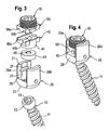
- shows an exploded view of the bone anchoring device according to a first embodiment.
- Fig. 4
- shows a perspective view of the bone anchoring device of
Fig. 3 in an assembled state. - Fig. 5
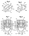
- shows a perspective view from the side of the first pressure element in a first embodiment.
- Fig. 6
- shows a perspective view of the second pressure element in a first embodiment.
- Fig. 7
- shows a partially sectional view of the bone anchoring device with the first and second pressure element according to the first embodiment.
- Fig. 8
- shows a partially sectional view of the bone anchoring device with the first and second pressure element according to a second embodiment.
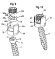
- Fig. 9
- shows an exploded perspective view of the bone anchoring device with a first and second pressure element according to a third embodiment.
- Fig. 10
- shows a perspective view of the bone anchoring device of
Fig. 9 in an assembled state. - The invention is now described in detail with reference to the embodiment of the stabilization device shown in
Figs. 1 to 8 . The stabilization device comprises a first polyaxial pedicle screws 1, asecond pedicle screw 2 and tworods - On each rod a
spring element rods rod connectors 5, 6. Therods second pedicle screw 2 and can slide through the first pedicle screw 1 as shown by the arrows. The sliding motion is limited by means of the rod connector 6 which connects the free ends of therods springs rod connector 5 limit the sliding motion of therods second pedicle screw 2. The springs provide elastic damping. Therod connectors 5, 6 are sleeve shaped with twochannels rods rod connectors 5, 6 connect therod rod connectors 5, 6 can be made of an elastomer material or any other body compatible material. - The
springs rods - The
rods - It should be noted that the rod connectors and the springs are only examples for the function of connecting the two rods, providing a stop and providing a damping to the sliding motion.
- Next, the first pedicle screw 1 will be described in detail with reference to
Figs. 3 to 7 . The pedicle screw 1 comprises ascrew element 10 with a threadedshank 11 and a spherically segment-shaped head 12. At the free end of the head 12 arecess 13 is provided for engagement with a tool. The pedicle screw 1 further comprises a receivingpart 20 with afirst end 21 and a second 22 and acoaxial bore 23 extending from the first end in the direction of the second end. At thesecond end 22 the bore 23 tapers to provide an opening and aseat 24 for thescrew head 12 as shown in particular inFig. 7 . - The
receiving part 20 further comprises arecess 25 extending from thefirst end 21 in the direction of thesecond end 22 which provides a channel through the receiving part in a direction perpendicular to the bore axis ofbore 23 for guiding through therods free legs first end 21 thefree legs internal thread 27 for cooperation with afixation screw 30. Thescrew element 10 and the receivingpart 20 as well as thefixation screw 30 are made of a rigid body compatible material, such as a body compatible metal like stainless steel or titanium or a titanium alloy, such as nitinol. - For locking the
head 12 and in consequence the angular position of thescrew element 10 within theseat 24 of the receiving 20 afirst pressure element 40 and asecond pressure element 50 are provided. Thefirst pressure element 40 and thesecond pressure element 50 also form guiding elements for guiding therods part 20. Thefirst pressure element 40 has a substantiallycylindrical body part 41 which is sized such that thefirst pressure element 40 can be inserted in the receiving part and moved in an axial direction within thebore 23. At its side facing thehead 12 of the screw element thefirst pressure element 40 comprises acylindrical recess 42 shown inFig. 7 in which acylindrical insert 43 is provided. Theinsert 43 has on its side facing thehead 12 of the screw element aspherical recess 44 the radius of which fits to the radius ofspherical head 12 of the screw element. - The
first pressure element 40 further comprises acuboid body part 45 which is shaped so as to fit in therecess 25 of the receivingpart 20 as shown in particular inFigs. 3 and 4 . The width of the rectangle corresponds to the width of therecess 25 and the length is selected such that the first pressure element is flush with theouter surface 28 of the receivingpart 20 as shown inFig. 4 . On its side opposite to therecess 42 the cuboid body part comprises two cylinder segment-shapedrecesses rods recesses coaxial bore 23 of the receivingpart 20. They form channels for receiving therods recesses rib 47 is formed between them. The depth of therecesses rods first pressure element 40 also has acoaxial bore 48 for providing access to thehead 12 of the screw element with a tool. Similarly, thecylindrical insert 43 has acoaxial bore 49. Thecylindrical body part 41 and thecuboid body part 25 are shown to be made in one piece so that cylindrical segment-shapedflanges channel first pressure element 40 within the receivingpart 20. Thecuboid body part 45 prevents rotation of the first pressure element within the receiving part once the first pressure element is inserted into therecess 25. - The
second pressure element 50 is substantially cuboid shaped with a width and length corresponding to that of thecuboid body part 45 of thefirst pressure element 40. Therefore, it also fits into therecess 25 of the receiving part. On its long sides it comprises two cylindrical segment-shapedflanges flanges first pressure element 40, thesecond pressure element 50 comprises acylindrical recess 52 and a coaxialcylindrical projection 53 in which a corresponding ring-shaped projection 31 and a cylindrical recess 32 of thefixation screw 30 engage, as shown inFig. 7 . Thereby, thefixation screw 30 can be rotatably connected to thepressure element 50. - On its side facing the first pressure element, the
second pressure element 50 comprises two longitudinal cylinder segment-shapedrecesses channels channels rib 57. - In the assembled state shown in
Fig. 7 the first pressure element presses via theinsert 43 onto thehead 12. Thesecond pressure element 50 presses onto thefirst pressure element 40 thereby providing closed channels for therods gap 60 to the wall of the channel. Since thefixation screw 30 is rotatably connected to the second pressure element, thefixation screw 30 can be tightened when thesecond pressure element 50 is inserted. - The first pressure element and the second pressure element can be made of a material which facilitates sliding of the
rods insert 43 is preferably made of the same material as thehead 12 of the screw, for example of a body compatible metal. Instead of providing theinsert 43 the first pressure element itself can have a spherical recess to press onto the head. Instead of providing the first and second pressure element of a material which facilitates sliding or which is coated or treated to facilitate sliding, therods - The
second pedicle screw 2 shown inFigs. 1, 2 and8 differs from the first pedicle screw 1 in the design of the first and second pressure elements. All other parts are identical and have the same reference numerals. Therefore, the description thereof is not repeated. The shape of the first pressure element 40' and of thesecond pressure element 50' of thesecond pedicle screw 2 is the same as that of thefirst pressure element 40 and thesecond pressure element 50 of the first pedicle screw 1. However, the size of thechannels 46a', 46b', 56a', 56b' is smaller than that of the channels of the first and second pressure element of the first pedicle screw. The radius of the channels is adapted to the radius of therods rods Fig. 8 , in the assembled state therods second pressure element 50'. - A second embodiment of the stabilization device is shown in
Figs. 9 and 10 without the rods. The second embodiment differs from the first embodiment described with reference toFigs. 1 to 8 only in the shape of the first andsecond pressure elements channels cylindrical body part 410. Therefore, thefirst pressure element 400 and thesecond pressure element 500 are arranged completely within the cylindrical bore 23 of the receiving part. - Modifications of the above described embodiments are conceivable. For example, the pedicle screws and the design of the pressure elements can be such that more than two rods can be accommodated. It is possible to use rods with different elastic properties. It is sufficient, if one of the pressure elements has the channels for guiding the rods, however, it is advantageous if the rods are guided from below and from the top by the channels. The shape of the lower part of the first pressure element can be flat, however, a shape adapted to the shape of the head of the
screw 12 is advantageous for distributing the pressure onto the head. - The fixation elementcan be a two-part fixation screw wherein the first screw element of a bushing type presses onto the first pressure element for locking of the
head 12 and a second screw element of a set screw type arranged within the first screw element presses onto the second pressure element for fixation of the rods in the embodiment shown inFig. 8 . - The receiving part can be shaped as a top loader as shown in the figures or a bottom loader in which the
screw element 10 is introduced from the bottom, i.e. the second end of the receiving part. - The shank of the screw element does not have to have a thread. It can be in the form of a hook, a nail or can have barb elements for anchoring in the bone.
- The springs can be also provided adjacent the outer stop 6. It is also conceivable that the rods themselves have an axial elastic spring portion.
- In use, first the screw elements of the pedicle screws 1, 2 which have been inserted into the receiving
parts 20 are screwed into adjacent vertebrae. The first pressure elements can be preassembled so that after alignment of the receiving parts therods rods - Next, after the receiving parts and the rods are aligned the angular position of the screw elements relative to the receiving parts is fixed by inserting the fixation screw together with the second pressure element and tightening the fixation screw. In the case of the
second pedicle screw 2 as shown inFigs. 1, 2 and8 therods screw head 12. In the case of the first pedicle screw only thehead 12 of the screw element is fixed while the rods can still slide within the channels. - As shown in
Fig. 1 the rods can slide through the receiving part of the first pedicle screw during flexion or extension of the spinal motion segment, whereby the sliding movement is limited by therod connectors 6 and 5 acting as stops and dampened by thesprings
Claims (15)
- Bone anchoring device comprisingan anchoring element (10) with an anchoring section (11) for anchoring in a bone part or a vertebra and a head (12);a receiving part (20) for receiving a stabilization rod (3a, 3b);wherein the receiving part (20) has a seat (24) for receiving the head (12) so that the head can pivot with respect to the receiving part;and wherein the receiving part comprises a first pressure element (40, 40', 400) which is movable in the receiving part so that it can be pressed onto the head (12) to lock the angular position of the head;
characterized in that at least two guiding channels (46a, 46b, 46a', 46b', 460a, 460b) are provided within the receiving part which have a distance from each other for guiding through at least two stabilizing rods (3a, 3b) so that the rods do not touch each other. - The bone anchoring device of claim 1, wherein the guiding channels are provided in the first pressure element on the side facing away from the head.
- The bone anchoring device of claim 1 or 2, wherein a second pressure element (50, 50', 500) is provided which acts either directly onto the first pressure element or onto the rods (3a, 3b).
- The bone anchoring device of claim 3, wherein the channels (56a, 56b, 56a', 56b', 560a, 560b) are provided at the second pressure element.
- The bone anchoring device of one of claims 1 to 5, wherein the channels are sized larger than the rods to allow the rods to slide therein.
- The bone anchoring device of claim 5, wherein the surface of the channels and/or the surface of the rods are treated or made of a material which facilitates sliding.
- The bone anchoring device of one of claims 1 to 4, wherein the size of the channels is the same or smaller than that of the rods so that the rods can be clamped therein.
- The bone anchoring device of one of claims 1 to 7, wherein the receiving part has a first end (21) and a second end (22) and a coaxial bore (23) extending from the first end in the direction of the second end in which the first pressure element is movable.
- The bone anchoring device of claim 8, wherein the second pressure element is movable in the bore.
- The bone anchoring device of one of claims 1 to 9, further comprising a fixation element (30) to fix the position of the head (12) in the receiving part.
- Stabilization device for stabilizing bone parts or vertebrae, the stabilization device comprisingtwo bone anchoring devices for anchoring in the bone parts or vertebrae, wherein at least one of the bone anchoring devices is a bone anchoring device according to one of claims 1 to 10; andat least two stabilization rods (3a, 3b).
- The stabilization device of claim 11, wherein one of the bone anchoring devices is slidably connected to the rods and the other bone anchoring device is fixedly connected to the rods.
- The stabilization device of claim 12, wherein at least one stop (5, 6) is provided for limiting the sliding movement of the rods.
- The stabilization device of one of claims 11 to 13, wherein the rods exhibit bending flexibility when a force component acts in a direction perpendicular to the rod axis.
- The stabilization device of one of claims 11 to 14, wherein the rods comprise a spring element (4a, 4b) for damping the sliding movement of the rods of for providing elasticity along the rod axis.
Priority Applications (8)
| Application Number | Priority Date | Filing Date | Title |
|---|---|---|---|
| ES08017644T ES2392362T3 (en) | 2008-10-08 | 2008-10-08 | Bone anchoring device and stabilization device for bone parts or vertebrae |
| EP08017644A EP2174608B1 (en) | 2008-10-08 | 2008-10-08 | Bone anchoring device and stabilization device for bone parts or vertebrae |
| CN200910204457.3A CN101716096B (en) | 2008-10-08 | 2009-09-29 | Bone anchoring device and stabilization device for bone parts or verterae comprising such a bone anchoring device |
| US12/571,299 US8795336B2 (en) | 2008-10-08 | 2009-09-30 | Bone anchoring device and stabilization device for bone parts or vertebrae comprising such a bone anchoring device |
| KR1020090094313A KR20100039809A (en) | 2008-10-08 | 2009-10-05 | Bone anchoring device and stabilization device for bone parts or verterae comprising such a bone anchoring device |
| JP2009231669A JP2010088887A (en) | 2008-10-08 | 2009-10-05 | Bone anchoring device and stabilizer equipped with this bone anchoring device for stabilizing bone part or vertebra |
| TW098133655A TW201014562A (en) | 2008-10-08 | 2009-10-05 | Bone anchoring device and stabilization device for bone parts or vertebrae comprising such a bone anchoring device |
| US14/315,684 US20140379031A1 (en) | 2008-10-08 | 2014-06-26 | Bone anchoring device and stabilization device for bone parts or vertebrae comprising such a bone anchoring device |
Applications Claiming Priority (1)
| Application Number | Priority Date | Filing Date | Title |
|---|---|---|---|
| EP08017644A EP2174608B1 (en) | 2008-10-08 | 2008-10-08 | Bone anchoring device and stabilization device for bone parts or vertebrae |
Publications (2)
| Publication Number | Publication Date |
|---|---|
| EP2174608A1 true EP2174608A1 (en) | 2010-04-14 |
| EP2174608B1 EP2174608B1 (en) | 2012-08-01 |
Family
ID=40212895
Family Applications (1)
| Application Number | Title | Priority Date | Filing Date |
|---|---|---|---|
| EP08017644A Not-in-force EP2174608B1 (en) | 2008-10-08 | 2008-10-08 | Bone anchoring device and stabilization device for bone parts or vertebrae |
Country Status (7)
| Country | Link |
|---|---|
| US (2) | US8795336B2 (en) |
| EP (1) | EP2174608B1 (en) |
| JP (1) | JP2010088887A (en) |
| KR (1) | KR20100039809A (en) |
| CN (1) | CN101716096B (en) |
| ES (1) | ES2392362T3 (en) |
| TW (1) | TW201014562A (en) |
Cited By (7)
| Publication number | Priority date | Publication date | Assignee | Title |
|---|---|---|---|---|
| EP2505155A1 (en) * | 2011-03-31 | 2012-10-03 | Spinelab AG | Spinal implant for stabilising and reinforcing spinal bodies of a spine |
| WO2012076005A3 (en) * | 2010-12-08 | 2012-10-04 | Aces Gmbh | Dynamic bone-anchoring device |
| EP2826429A1 (en) * | 2013-07-19 | 2015-01-21 | Biedermann Technologies GmbH & Co. KG | Polyaxial bone anchoring device |
| EP3100692A1 (en) * | 2015-06-04 | 2016-12-07 | Zimmer Spine | Spinal dynamic stabilization system |
| FR3073731A1 (en) * | 2017-11-22 | 2019-05-24 | Hassan Razian | SYSTEM FOR CONNECTING TWO PORTIONS OF BONES BETWEEN THEM WHEN ONE MUST MOVE IN RELATION TO THE OTHER |
| FR3106968A1 (en) * | 2020-02-06 | 2021-08-13 | Hassan Razian | System for connecting at least two portions of bone |
| EP3991673A1 (en) * | 2020-10-29 | 2022-05-04 | Biedermann Technologies GmbH & Co. KG | Coupling device for coupling a rod to a bone anchor |
Families Citing this family (78)
| Publication number | Priority date | Publication date | Assignee | Title |
|---|---|---|---|---|
| US7833250B2 (en) | 2004-11-10 | 2010-11-16 | Jackson Roger P | Polyaxial bone screw with helically wound capture connection |
| US7862587B2 (en) | 2004-02-27 | 2011-01-04 | Jackson Roger P | Dynamic stabilization assemblies, tool set and method |
| US10729469B2 (en) | 2006-01-09 | 2020-08-04 | Roger P. Jackson | Flexible spinal stabilization assembly with spacer having off-axis core member |
| US8292926B2 (en) | 2005-09-30 | 2012-10-23 | Jackson Roger P | Dynamic stabilization connecting member with elastic core and outer sleeve |
| US10258382B2 (en) | 2007-01-18 | 2019-04-16 | Roger P. Jackson | Rod-cord dynamic connection assemblies with slidable bone anchor attachment members along the cord |
| US8353932B2 (en) | 2005-09-30 | 2013-01-15 | Jackson Roger P | Polyaxial bone anchor assembly with one-piece closure, pressure insert and plastic elongate member |
| US8876868B2 (en) | 2002-09-06 | 2014-11-04 | Roger P. Jackson | Helical guide and advancement flange with radially loaded lip |
| US7621918B2 (en) | 2004-11-23 | 2009-11-24 | Jackson Roger P | Spinal fixation tool set and method |
| US7377923B2 (en) | 2003-05-22 | 2008-05-27 | Alphatec Spine, Inc. | Variable angle spinal screw assembly |
| US7766915B2 (en) | 2004-02-27 | 2010-08-03 | Jackson Roger P | Dynamic fixation assemblies with inner core and outer coil-like member |
| US8814911B2 (en) | 2003-06-18 | 2014-08-26 | Roger P. Jackson | Polyaxial bone screw with cam connection and lock and release insert |
| US8366753B2 (en) | 2003-06-18 | 2013-02-05 | Jackson Roger P | Polyaxial bone screw assembly with fixed retaining structure |
| US8926670B2 (en) | 2003-06-18 | 2015-01-06 | Roger P. Jackson | Polyaxial bone screw assembly |
| US7776067B2 (en) | 2005-05-27 | 2010-08-17 | Jackson Roger P | Polyaxial bone screw with shank articulation pressure insert and method |
| US7527638B2 (en) | 2003-12-16 | 2009-05-05 | Depuy Spine, Inc. | Methods and devices for minimally invasive spinal fixation element placement |
| US7179261B2 (en) | 2003-12-16 | 2007-02-20 | Depuy Spine, Inc. | Percutaneous access devices and bone anchor assemblies |
| US11419642B2 (en) | 2003-12-16 | 2022-08-23 | Medos International Sarl | Percutaneous access devices and bone anchor assemblies |
| US7160300B2 (en) | 2004-02-27 | 2007-01-09 | Jackson Roger P | Orthopedic implant rod reduction tool set and method |
| US8152810B2 (en) | 2004-11-23 | 2012-04-10 | Jackson Roger P | Spinal fixation tool set and method |
| AU2004317551B2 (en) | 2004-02-27 | 2008-12-04 | Roger P. Jackson | Orthopedic implant rod reduction tool set and method |
| US11241261B2 (en) | 2005-09-30 | 2022-02-08 | Roger P Jackson | Apparatus and method for soft spinal stabilization using a tensionable cord and releasable end structure |
| US8066739B2 (en) | 2004-02-27 | 2011-11-29 | Jackson Roger P | Tool system for dynamic spinal implants |
| US7651502B2 (en) | 2004-09-24 | 2010-01-26 | Jackson Roger P | Spinal fixation tool set and method for rod reduction and fastener insertion |
| US8926672B2 (en) | 2004-11-10 | 2015-01-06 | Roger P. Jackson | Splay control closure for open bone anchor |
| US9980753B2 (en) * | 2009-06-15 | 2018-05-29 | Roger P Jackson | pivotal anchor with snap-in-place insert having rotation blocking extensions |
| WO2006057837A1 (en) | 2004-11-23 | 2006-06-01 | Jackson Roger P | Spinal fixation tool attachment structure |
| US9393047B2 (en) | 2009-06-15 | 2016-07-19 | Roger P. Jackson | Polyaxial bone anchor with pop-on shank and friction fit retainer with low profile edge lock |
| US8444681B2 (en) | 2009-06-15 | 2013-05-21 | Roger P. Jackson | Polyaxial bone anchor with pop-on shank, friction fit retainer and winged insert |
| US9168069B2 (en) | 2009-06-15 | 2015-10-27 | Roger P. Jackson | Polyaxial bone anchor with pop-on shank and winged insert with lower skirt for engaging a friction fit retainer |
| US9216041B2 (en) * | 2009-06-15 | 2015-12-22 | Roger P. Jackson | Spinal connecting members with tensioned cords and rigid sleeves for engaging compression inserts |
| US8308782B2 (en) | 2004-11-23 | 2012-11-13 | Jackson Roger P | Bone anchors with longitudinal connecting member engaging inserts and closures for fixation and optional angulation |
| US7901437B2 (en) | 2007-01-26 | 2011-03-08 | Jackson Roger P | Dynamic stabilization member with molded connection |
| US8105368B2 (en) | 2005-09-30 | 2012-01-31 | Jackson Roger P | Dynamic stabilization connecting member with slitted core and outer sleeve |
| US8366745B2 (en) | 2007-05-01 | 2013-02-05 | Jackson Roger P | Dynamic stabilization assembly having pre-compressed spacers with differential displacements |
| US8475498B2 (en) | 2007-01-18 | 2013-07-02 | Roger P. Jackson | Dynamic stabilization connecting member with cord connection |
| US10383660B2 (en) | 2007-05-01 | 2019-08-20 | Roger P. Jackson | Soft stabilization assemblies with pretensioned cords |
| US20090105756A1 (en) | 2007-10-23 | 2009-04-23 | Marc Richelsoph | Spinal implant |
| US8784453B1 (en) | 2008-06-09 | 2014-07-22 | Melvin Law | Dynamic spinal stabilization system |
| US8043340B1 (en) * | 2008-06-09 | 2011-10-25 | Melvin Law | Dynamic spinal stabilization system |
| JP2012529969A (en) | 2008-08-01 | 2012-11-29 | ロジャー・ピー・ジャクソン | Longitudinal connecting member with tensioning cord with sleeve |
| ES2387512T3 (en) * | 2008-09-05 | 2012-09-25 | Biedermann Technologies Gmbh & Co. Kg | Bone stabilization device, in particular for the spine |
| US9603629B2 (en) | 2008-09-09 | 2017-03-28 | Intelligent Implant Systems Llc | Polyaxial screw assembly |
| GB2465156B (en) * | 2008-11-05 | 2012-09-26 | Dalmatic Lystrup As | Bone fixation system |
| US9668771B2 (en) | 2009-06-15 | 2017-06-06 | Roger P Jackson | Soft stabilization assemblies with off-set connector |
| EP2757988A4 (en) | 2009-06-15 | 2015-08-19 | Jackson Roger P | Polyaxial bone anchor with pop-on shank and winged insert with friction fit compressive collet |
| US8998959B2 (en) | 2009-06-15 | 2015-04-07 | Roger P Jackson | Polyaxial bone anchors with pop-on shank, fully constrained friction fit retainer and lock and release insert |
| US11229457B2 (en) | 2009-06-15 | 2022-01-25 | Roger P. Jackson | Pivotal bone anchor assembly with insert tool deployment |
| US11464549B2 (en) | 2009-06-15 | 2022-10-11 | Roger P. Jackson | Pivotal bone anchor assembly with horizontal tool engagement grooves and insert with upright arms having flared outer portions |
| AU2010303934B2 (en) | 2009-10-05 | 2014-03-27 | Roger P. Jackson | Polyaxial bone anchor with non-pivotable retainer and pop-on shank, some with friction fit |
| US20230404629A1 (en) * | 2010-05-14 | 2023-12-21 | Roger P. Jackson | Pivotal bone anchor assembly and method for use thereof |
| US9113960B2 (en) * | 2010-06-08 | 2015-08-25 | Globus Medical, Inc. | Conforming bone stabilization receiver |
| JP2013540468A (en) | 2010-09-08 | 2013-11-07 | ロジャー・ピー・ジャクソン | Dynamic fixing member having an elastic part and an inelastic part |
| GB2502449A (en) | 2010-11-02 | 2013-11-27 | Roger P Jackson | Polyaxial bone anchor with pop-on shank and pivotable retainer |
| WO2012128825A1 (en) | 2011-03-24 | 2012-09-27 | Jackson Roger P | Polyaxial bone anchor with compound articulation and pop-on shank |
| CN103987327A (en) | 2011-10-05 | 2014-08-13 | 马克·A·多德森 | Modular retractor and related method |
| US8911479B2 (en) | 2012-01-10 | 2014-12-16 | Roger P. Jackson | Multi-start closures for open implants |
| CN103356275B (en) * | 2012-03-29 | 2016-06-01 | 董健文 | A kind of Micro-movement lumber pedicle screw elastic-fixation system |
| US8911478B2 (en) | 2012-11-21 | 2014-12-16 | Roger P. Jackson | Splay control closure for open bone anchor |
| US10058354B2 (en) | 2013-01-28 | 2018-08-28 | Roger P. Jackson | Pivotal bone anchor assembly with frictional shank head seating surfaces |
| US8852239B2 (en) | 2013-02-15 | 2014-10-07 | Roger P Jackson | Sagittal angle screw with integral shank and receiver |
| US9044273B2 (en) | 2013-10-07 | 2015-06-02 | Intelligent Implant Systems, Llc | Polyaxial plate rod system and surgical procedure |
| US9566092B2 (en) | 2013-10-29 | 2017-02-14 | Roger P. Jackson | Cervical bone anchor with collet retainer and outer locking sleeve |
| US9717533B2 (en) | 2013-12-12 | 2017-08-01 | Roger P. Jackson | Bone anchor closure pivot-splay control flange form guide and advancement structure |
| US9451993B2 (en) | 2014-01-09 | 2016-09-27 | Roger P. Jackson | Bi-radial pop-on cervical bone anchor |
| EP2939638B1 (en) * | 2014-04-30 | 2018-04-11 | Zimmer GmbH | A set for connecting a prosthetic assembly of an artificial joint to a bone |
| US9597119B2 (en) * | 2014-06-04 | 2017-03-21 | Roger P. Jackson | Polyaxial bone anchor with polymer sleeve |
| US10064658B2 (en) | 2014-06-04 | 2018-09-04 | Roger P. Jackson | Polyaxial bone anchor with insert guides |
| US9949763B2 (en) * | 2014-06-13 | 2018-04-24 | Warsaw Orthopedic, Inc. | Bone fastener and methods of use |
| CN105078562A (en) * | 2015-03-13 | 2015-11-25 | 上海三友医疗器械有限公司 | Medical screw with connector |
| JP6892993B2 (en) * | 2016-01-22 | 2021-06-23 | 京セラ株式会社 | Spinal screw assembly |
| ES2910424T3 (en) * | 2017-03-10 | 2022-05-12 | Univ Washington | Methods and systems for measuring and evaluating the stability of medical implants |
| WO2020102787A1 (en) | 2018-11-16 | 2020-05-22 | Surber, James L. | Pivotal bone anchor assembly having a deployable collet insert with internal pressure ring |
| EP3897414A4 (en) | 2018-12-21 | 2022-09-28 | Paradigm Spine, LLC. | Modular spine stabilization system and associated instruments |
| US20200390472A1 (en) * | 2019-02-27 | 2020-12-17 | Orthopediatrics Corp. | Bone anchor with cord retention features |
| US20200323562A1 (en) * | 2019-04-12 | 2020-10-15 | Orthopediatrics Corp. | Dual tether support of vertebra |
| US11337734B2 (en) | 2019-05-22 | 2022-05-24 | Nuvasive, Inc. | Posterior spinal fixation screws |
| US11723691B2 (en) * | 2019-12-25 | 2023-08-15 | Apifix Ltd | Biasing device for spinal device |
| US20220110661A1 (en) * | 2020-10-12 | 2022-04-14 | Globus Medical, Inc. | Scoliosis correction systems, methods, and instruments |
Citations (10)
| Publication number | Priority date | Publication date | Assignee | Title |
|---|---|---|---|---|
| US5797911A (en) * | 1996-09-24 | 1998-08-25 | Sdgi Holdings, Inc. | Multi-axial bone screw assembly |
| US6206879B1 (en) * | 1998-10-22 | 2001-03-27 | Aesculap Ag & Co. Kg | Osteosynthetic holding system |
| WO2003034930A1 (en) * | 2001-10-23 | 2003-05-01 | Biedermann Motech Gmbh | Bone fixation device and screw therefor |
| US20040049190A1 (en) | 2002-08-09 | 2004-03-11 | Biedermann Motech Gmbh | Dynamic stabilization device for bones, in particular for vertebrae |
| US20040111088A1 (en) * | 2002-12-06 | 2004-06-10 | Picetti George D. | Multi-rod bone attachment member |
| FR2863860A1 (en) * | 2003-12-17 | 2005-06-24 | Sdgi Holdings Inc | Bone anchor screw for correcting deformations of vertebral column, has longitudinal rods arranged inside head, in sequenced manner in two columns, and cap placed on head in unclamped state, before introduction of rods in head |
| US20050171537A1 (en) * | 2001-11-27 | 2005-08-04 | Christian Mazel | Connector for vertebral anchoring system |
| EP1800613A1 (en) * | 2005-12-23 | 2007-06-27 | BIEDERMANN MOTECH GmbH | Flexible stabilization device for dynamic stabilization of bones or vertebrae |
| EP1800614A1 (en) | 2005-12-23 | 2007-06-27 | BIEDERMANN MOTECH GmbH | Dynamic stabilization device for bones or vertebrae |
| WO2008036578A2 (en) * | 2006-09-18 | 2008-03-27 | Warsaw Orthopedic, Inc | Orthopedic plate system |
Family Cites Families (73)
| Publication number | Priority date | Publication date | Assignee | Title |
|---|---|---|---|---|
| GB1519139A (en) * | 1974-06-18 | 1978-07-26 | Crock H V And Pericic L | L securing elongate members to structurs more especially in surgical procedures |
| FR2689750B1 (en) * | 1992-04-10 | 1997-01-31 | Eurosurgical | BONE ANCHORING ELEMENT AND SPINAL OSTEOSYNTHESIS DEVICE INCORPORATING SUCH ELEMENTS. |
| FR2697992B1 (en) * | 1992-11-18 | 1994-12-30 | Eurosurgical | Device for attaching to a rod of an organ, in particular for spinal orthopedic instrumentation. |
| US6413257B1 (en) * | 1997-05-15 | 2002-07-02 | Surgical Dynamics, Inc. | Clamping connector for spinal fixation systems |
| US6302888B1 (en) * | 1999-03-19 | 2001-10-16 | Interpore Cross International | Locking dovetail and self-limiting set screw assembly for a spinal stabilization member |
| DE50106374D1 (en) * | 2000-09-18 | 2005-07-07 | Zimmer Gmbh Winterthur | Pedicle screw for intervertebral support elements |
| FR2829014B1 (en) * | 2001-09-03 | 2005-04-08 | Stryker Spine | SPINAL OSTEOSYNTHESIS SYSTEM COMPRISING A SUPPORT SKATE |
| US6793657B2 (en) * | 2001-09-10 | 2004-09-21 | Solco Biomedical Co., Ltd. | Spine fixing apparatus |
| FR2831049B1 (en) * | 2001-10-18 | 2004-08-13 | Ldr Medical | PLATE FOR OSTEOSYNTHESIS DEVICE AND PRE-ASSEMBLY METHOD |
| FR2831048B1 (en) * | 2001-10-18 | 2004-09-17 | Ldr Medical | PROGRESSIVE APPROACH OSTEOSYNTHESIS DEVICE AND PRE-ASSEMBLY PROCESS |
| US6783527B2 (en) * | 2001-10-30 | 2004-08-31 | Sdgi Holdings, Inc. | Flexible spinal stabilization system and method |
| CN1432343A (en) * | 2002-01-17 | 2003-07-30 | 英属维京群岛商冠亚生技控股集团股份有限公司 | Rotary controlled vertebra fixture |
| FR2835174B1 (en) * | 2002-01-31 | 2004-03-19 | Materiel Orthopedique En Abreg | CONNECTOR FOR SPINAL OSTEOSYNTHESIS DEVICE, BONE ANCHOR CONNECTOR / MEMBER ASSEMBLY AND SPINAL OSTEOSYNTHESIS DEVICE USING THE SAME |
| US20040015166A1 (en) * | 2002-07-22 | 2004-01-22 | Gorek Josef E. | System and method for stabilizing the spine by securing spine stabilization rods in crossed disposition |
| US7250054B2 (en) * | 2002-08-28 | 2007-07-31 | Smith & Nephew, Inc. | Systems, methods, and apparatuses for clamping and reclamping an orthopedic surgical cable |
| JP4047112B2 (en) * | 2002-09-12 | 2008-02-13 | 昭和医科工業株式会社 | Rod part fixing structure of vertebra connecting member |
| FR2845269B1 (en) * | 2002-10-07 | 2005-06-24 | Spine Next Sa | PLATE FASTENING SYSTEM |
| US7473267B2 (en) * | 2003-04-25 | 2009-01-06 | Warsaw Orthopedic, Inc. | System and method for minimally invasive posterior fixation |
| US7967850B2 (en) * | 2003-06-18 | 2011-06-28 | Jackson Roger P | Polyaxial bone anchor with helical capture connection, insert and dual locking assembly |
| US7766915B2 (en) * | 2004-02-27 | 2010-08-03 | Jackson Roger P | Dynamic fixation assemblies with inner core and outer coil-like member |
| US7776067B2 (en) * | 2005-05-27 | 2010-08-17 | Jackson Roger P | Polyaxial bone screw with shank articulation pressure insert and method |
| US7799082B2 (en) * | 2003-08-05 | 2010-09-21 | Flexuspine, Inc. | Artificial functional spinal unit system and method for use |
| US20050203513A1 (en) * | 2003-09-24 | 2005-09-15 | Tae-Ahn Jahng | Spinal stabilization device |
| US8979900B2 (en) * | 2003-09-24 | 2015-03-17 | DePuy Synthes Products, LLC | Spinal stabilization device |
| US7083622B2 (en) * | 2003-11-10 | 2006-08-01 | Simonson Peter M | Artificial facet joint and method |
| US7862586B2 (en) * | 2003-11-25 | 2011-01-04 | Life Spine, Inc. | Spinal stabilization systems |
| DE102004011685A1 (en) * | 2004-03-09 | 2005-09-29 | Biedermann Motech Gmbh | Spine supporting element, comprising spiraled grooves at outer surface and three plain areas |
| US7744635B2 (en) * | 2004-06-09 | 2010-06-29 | Spinal Generations, Llc | Spinal fixation system |
| US7854752B2 (en) * | 2004-08-09 | 2010-12-21 | Theken Spine, Llc | System and method for dynamic skeletal stabilization |
| US7766945B2 (en) * | 2004-08-10 | 2010-08-03 | Lanx, Inc. | Screw and rod fixation system |
| BRPI0419057A (en) * | 2004-09-22 | 2007-12-11 | Kyung-Woo Park | spinal fixation |
| US7896906B2 (en) * | 2004-12-30 | 2011-03-01 | Depuy Spine, Inc. | Artificial facet joint |
| US7572280B2 (en) * | 2004-10-05 | 2009-08-11 | Warsaw Orthopedic, Inc. | Multi-axial anchor assemblies for spinal implants and methods |
| US7935134B2 (en) * | 2004-10-20 | 2011-05-03 | Exactech, Inc. | Systems and methods for stabilization of bone structures |
| US20120029568A1 (en) * | 2006-01-09 | 2012-02-02 | Jackson Roger P | Spinal connecting members with radiused rigid sleeves and tensioned cords |
| US9393047B2 (en) * | 2009-06-15 | 2016-07-19 | Roger P. Jackson | Polyaxial bone anchor with pop-on shank and friction fit retainer with low profile edge lock |
| US7744636B2 (en) * | 2004-12-16 | 2010-06-29 | Aesculap Ii, Inc. | Locking mechanism |
| US7862588B2 (en) * | 2005-02-18 | 2011-01-04 | Samy Abdou | Devices and methods for dynamic fixation of skeletal structure |
| US7338491B2 (en) * | 2005-03-22 | 2008-03-04 | Spinefrontier Inc | Spinal fixation locking mechanism |
| US7722651B2 (en) * | 2005-10-21 | 2010-05-25 | Depuy Spine, Inc. | Adjustable bone screw assembly |
| US20070191842A1 (en) * | 2006-01-30 | 2007-08-16 | Sdgi Holdings, Inc. | Spinal fixation devices and methods of use |
| US8118869B2 (en) * | 2006-03-08 | 2012-02-21 | Flexuspine, Inc. | Dynamic interbody device |
| US8858600B2 (en) * | 2006-06-08 | 2014-10-14 | Spinadyne, Inc. | Dynamic spinal stabilization device |
| US7905906B2 (en) * | 2006-06-08 | 2011-03-15 | Disc Motion Technologies, Inc. | System and method for lumbar arthroplasty |
| US8361130B2 (en) * | 2006-10-06 | 2013-01-29 | Depuy Spine, Inc. | Bone screw fixation |
| US8066744B2 (en) * | 2006-11-10 | 2011-11-29 | Warsaw Orthopedic, Inc. | Keyed crown orientation for multi-axial screws |
| US8366745B2 (en) * | 2007-05-01 | 2013-02-05 | Jackson Roger P | Dynamic stabilization assembly having pre-compressed spacers with differential displacements |
| US8109975B2 (en) * | 2007-01-30 | 2012-02-07 | Warsaw Orthopedic, Inc. | Collar bore configuration for dynamic spinal stabilization assembly |
| US8029547B2 (en) * | 2007-01-30 | 2011-10-04 | Warsaw Orthopedic, Inc. | Dynamic spinal stabilization assembly with sliding collars |
| EP2301456B1 (en) * | 2007-02-23 | 2013-04-17 | Biedermann Technologies GmbH & Co. KG | Rod connector for stabilizing vertebrae |
| WO2008106582A2 (en) * | 2007-02-28 | 2008-09-04 | Mass Modular Spine System | Tension fixation system |
| US8292929B2 (en) * | 2007-03-16 | 2012-10-23 | Zimmer Spine, Inc. | Dynamic spinal stabilization system and method of using the same |
| US7942910B2 (en) * | 2007-05-16 | 2011-05-17 | Ortho Innovations, Llc | Polyaxial bone screw |
| EP2160158A4 (en) * | 2007-05-31 | 2013-06-26 | Roger P Jackson | Dynamic stabilization connecting member with pre-tensioned solid core |
| US8083777B2 (en) * | 2007-06-15 | 2011-12-27 | Robert Reid, Inc. | System and method for polyaxially adjustable bone anchorage |
| US20090088799A1 (en) * | 2007-10-01 | 2009-04-02 | Chung-Chun Yeh | Spinal fixation device having a flexible cable and jointed components received thereon |
| GB0720762D0 (en) * | 2007-10-24 | 2007-12-05 | Depuy Spine Sorl | Assembly for orthopaedic surgery |
| EP2229126A4 (en) * | 2007-12-15 | 2010-12-29 | Brian D Parlato | Flexible rod assembly for spinal fixation |
| US8425564B2 (en) * | 2008-01-03 | 2013-04-23 | P. Douglas Kiester | Spine reconstruction rod extender |
| US8366746B2 (en) * | 2008-01-03 | 2013-02-05 | Kiester P Douglas | Spine reconstruction rod extender |
| EP2244644A1 (en) * | 2008-02-07 | 2010-11-03 | K2M, Inc. | Automatic lengthening bone fixation device |
| US10973556B2 (en) * | 2008-06-17 | 2021-04-13 | DePuy Synthes Products, Inc. | Adjustable implant assembly |
| JP2012529969A (en) * | 2008-08-01 | 2012-11-29 | ロジャー・ピー・ジャクソン | Longitudinal connecting member with tensioning cord with sleeve |
| ES2376135T3 (en) * | 2008-08-12 | 2012-03-09 | Biedermann Motech Gmbh | MODULAR SYSTEM FOR THE STABILIZATION OF THE VERTEBRAL COLUMN. |
| US9603629B2 (en) * | 2008-09-09 | 2017-03-28 | Intelligent Implant Systems Llc | Polyaxial screw assembly |
| US8080040B2 (en) * | 2008-10-29 | 2011-12-20 | Warsaw Orthopedic, Inc. | Anchor with two member securing mechanism for attaching an elongated member to a bone |
| EP2376008A1 (en) * | 2008-12-22 | 2011-10-19 | Synthes GmbH | Variable tension spine fixation rod |
| US8236032B2 (en) * | 2009-10-20 | 2012-08-07 | Depuy Spine, Inc. | Spinal implant with a flexible extension element |
| US20110196430A1 (en) * | 2010-02-10 | 2011-08-11 | Walsh David A | Spinal fixation assembly with intermediate element |
| US8740945B2 (en) * | 2010-04-07 | 2014-06-03 | Zimmer Spine, Inc. | Dynamic stabilization system using polyaxial screws |
| AU2011264818B2 (en) * | 2010-06-10 | 2015-06-18 | Globus Medical, Inc. | Low-profile, uniplanar bone screw |
| US8852239B2 (en) * | 2013-02-15 | 2014-10-07 | Roger P Jackson | Sagittal angle screw with integral shank and receiver |
| ES2603204T3 (en) * | 2013-07-19 | 2017-02-24 | Biedermann Technologies Gmbh & Co. Kg | Polyaxial bone anchoring device |
-
2008
- 2008-10-08 EP EP08017644A patent/EP2174608B1/en not_active Not-in-force
- 2008-10-08 ES ES08017644T patent/ES2392362T3/en active Active
-
2009
- 2009-09-29 CN CN200910204457.3A patent/CN101716096B/en not_active Expired - Fee Related
- 2009-09-30 US US12/571,299 patent/US8795336B2/en active Active
- 2009-10-05 TW TW098133655A patent/TW201014562A/en unknown
- 2009-10-05 KR KR1020090094313A patent/KR20100039809A/en active IP Right Grant
- 2009-10-05 JP JP2009231669A patent/JP2010088887A/en not_active Ceased
-
2014
- 2014-06-26 US US14/315,684 patent/US20140379031A1/en not_active Abandoned
Patent Citations (10)
| Publication number | Priority date | Publication date | Assignee | Title |
|---|---|---|---|---|
| US5797911A (en) * | 1996-09-24 | 1998-08-25 | Sdgi Holdings, Inc. | Multi-axial bone screw assembly |
| US6206879B1 (en) * | 1998-10-22 | 2001-03-27 | Aesculap Ag & Co. Kg | Osteosynthetic holding system |
| WO2003034930A1 (en) * | 2001-10-23 | 2003-05-01 | Biedermann Motech Gmbh | Bone fixation device and screw therefor |
| US20050171537A1 (en) * | 2001-11-27 | 2005-08-04 | Christian Mazel | Connector for vertebral anchoring system |
| US20040049190A1 (en) | 2002-08-09 | 2004-03-11 | Biedermann Motech Gmbh | Dynamic stabilization device for bones, in particular for vertebrae |
| US20040111088A1 (en) * | 2002-12-06 | 2004-06-10 | Picetti George D. | Multi-rod bone attachment member |
| FR2863860A1 (en) * | 2003-12-17 | 2005-06-24 | Sdgi Holdings Inc | Bone anchor screw for correcting deformations of vertebral column, has longitudinal rods arranged inside head, in sequenced manner in two columns, and cap placed on head in unclamped state, before introduction of rods in head |
| EP1800613A1 (en) * | 2005-12-23 | 2007-06-27 | BIEDERMANN MOTECH GmbH | Flexible stabilization device for dynamic stabilization of bones or vertebrae |
| EP1800614A1 (en) | 2005-12-23 | 2007-06-27 | BIEDERMANN MOTECH GmbH | Dynamic stabilization device for bones or vertebrae |
| WO2008036578A2 (en) * | 2006-09-18 | 2008-03-27 | Warsaw Orthopedic, Inc | Orthopedic plate system |
Cited By (10)
| Publication number | Priority date | Publication date | Assignee | Title |
|---|---|---|---|---|
| WO2012076005A3 (en) * | 2010-12-08 | 2012-10-04 | Aces Gmbh | Dynamic bone-anchoring device |
| EP2505155A1 (en) * | 2011-03-31 | 2012-10-03 | Spinelab AG | Spinal implant for stabilising and reinforcing spinal bodies of a spine |
| EP2826429A1 (en) * | 2013-07-19 | 2015-01-21 | Biedermann Technologies GmbH & Co. KG | Polyaxial bone anchoring device |
| EP3100692A1 (en) * | 2015-06-04 | 2016-12-07 | Zimmer Spine | Spinal dynamic stabilization system |
| EP3100693A1 (en) * | 2015-06-04 | 2016-12-07 | Zimmer Spine | Dynamic stabilization system |
| US10098670B2 (en) | 2015-06-04 | 2018-10-16 | Zimmer Spine S.A.S. | Dynamic stabilization system |
| FR3073731A1 (en) * | 2017-11-22 | 2019-05-24 | Hassan Razian | SYSTEM FOR CONNECTING TWO PORTIONS OF BONES BETWEEN THEM WHEN ONE MUST MOVE IN RELATION TO THE OTHER |
| FR3106968A1 (en) * | 2020-02-06 | 2021-08-13 | Hassan Razian | System for connecting at least two portions of bone |
| EP3991673A1 (en) * | 2020-10-29 | 2022-05-04 | Biedermann Technologies GmbH & Co. KG | Coupling device for coupling a rod to a bone anchor |
| US11660123B2 (en) | 2020-10-29 | 2023-05-30 | Biedermann Technologies Gmbh & Co. Kg | Coupling device for coupling a rod to a bone anchor |
Also Published As
| Publication number | Publication date |
|---|---|
| KR20100039809A (en) | 2010-04-16 |
| US20100087865A1 (en) | 2010-04-08 |
| CN101716096B (en) | 2014-08-06 |
| TW201014562A (en) | 2010-04-16 |
| JP2010088887A (en) | 2010-04-22 |
| ES2392362T3 (en) | 2012-12-10 |
| US20140379031A1 (en) | 2014-12-25 |
| CN101716096A (en) | 2010-06-02 |
| EP2174608B1 (en) | 2012-08-01 |
| US8795336B2 (en) | 2014-08-05 |
Similar Documents
| Publication | Publication Date | Title |
|---|---|---|
| EP2174608B1 (en) | Bone anchoring device and stabilization device for bone parts or vertebrae | |
| EP2153786B1 (en) | Modular system for the stabilization of the spinal column | |
| EP1800614B1 (en) | Dynamic stabilization device for bones or vertebrae | |
| JP5215553B2 (en) | Flexible stabilization device for dynamic stabilization of bone or vertebra | |
| US9451988B2 (en) | Rod-shaped implant in particular for stabilizing the spinal column and stabilization device including such a rod-shaped implant | |
| US9655652B2 (en) | Bone anchoring device | |
| EP3158957B1 (en) | Coupling device for coupling a bone anchor to a rod and bone anchoring device with such a coupling device | |
| EP2016916A1 (en) | Bone anchoring device | |
| EP2105101A1 (en) | Bone anchoring device | |
| US20080215095A1 (en) | Stabilization device for stabilizing bones of a vertebra and rod connector used therefor | |
| EP1900334A1 (en) | Bone anchoring device | |
| EP2484300A1 (en) | Bone anchoring element and stabilization device for bones, in particular for the spinal column | |
| AU2016232241B2 (en) | Polyaxial pedicle screw with a head in the shape of a ball segment |
Legal Events
| Date | Code | Title | Description |
|---|---|---|---|
| PUAI | Public reference made under article 153(3) epc to a published international application that has entered the european phase |
Free format text: ORIGINAL CODE: 0009012 |
|
| AK | Designated contracting states |
Kind code of ref document: A1 Designated state(s): AT BE BG CH CY CZ DE DK EE ES FI FR GB GR HR HU IE IS IT LI LT LU LV MC MT NL NO PL PT RO SE SI SK TR |
|
| AX | Request for extension of the european patent |
Extension state: AL BA MK RS |
|
| 17P | Request for examination filed |
Effective date: 20100521 |
|
| 17Q | First examination report despatched |
Effective date: 20100622 |
|
| AKX | Designation fees paid |
Designated state(s): CH DE ES FR GB IT LI |
|
| GRAP | Despatch of communication of intention to grant a patent |
Free format text: ORIGINAL CODE: EPIDOSNIGR1 |
|
| RIC1 | Information provided on ipc code assigned before grant |
Ipc: A61B 17/70 20060101AFI20120113BHEP |
|
| RAP1 | Party data changed (applicant data changed or rights of an application transferred) |
Owner name: BIEDERMANN TECHNOLOGIES GMBH & CO. KG |
|
| GRAS | Grant fee paid |
Free format text: ORIGINAL CODE: EPIDOSNIGR3 |
|
| GRAA | (expected) grant |
Free format text: ORIGINAL CODE: 0009210 |
|
| AK | Designated contracting states |
Kind code of ref document: B1 Designated state(s): CH DE ES FR GB IT LI |
|
| REG | Reference to a national code |
Ref country code: GB Ref legal event code: FG4D |
|
| REG | Reference to a national code |
Ref country code: CH Ref legal event code: NV Representative=s name: NOVAGRAAF INTERNATIONAL SA Ref country code: CH Ref legal event code: EP |
|
| REG | Reference to a national code |
Ref country code: DE Ref legal event code: R096 Ref document number: 602008017503 Country of ref document: DE Effective date: 20120927 |
|
| REG | Reference to a national code |
Ref country code: ES Ref legal event code: FG2A Ref document number: 2392362 Country of ref document: ES Kind code of ref document: T3 Effective date: 20121210 |
|
| PLBE | No opposition filed within time limit |
Free format text: ORIGINAL CODE: 0009261 |
|
| STAA | Information on the status of an ep patent application or granted ep patent |
Free format text: STATUS: NO OPPOSITION FILED WITHIN TIME LIMIT |
|
| 26N | No opposition filed |
Effective date: 20130503 |
|
| REG | Reference to a national code |
Ref country code: DE Ref legal event code: R097 Ref document number: 602008017503 Country of ref document: DE Effective date: 20130503 |
|
| REG | Reference to a national code |
Ref country code: FR Ref legal event code: PLFP Year of fee payment: 8 |
|
| PGFP | Annual fee paid to national office [announced via postgrant information from national office to epo] |
Ref country code: GB Payment date: 20151026 Year of fee payment: 8 Ref country code: IT Payment date: 20151026 Year of fee payment: 8 |
|
| PGFP | Annual fee paid to national office [announced via postgrant information from national office to epo] |
Ref country code: FR Payment date: 20151026 Year of fee payment: 8 Ref country code: ES Payment date: 20151023 Year of fee payment: 8 |
|
| GBPC | Gb: european patent ceased through non-payment of renewal fee |
Effective date: 20161008 |
|
| REG | Reference to a national code |
Ref country code: FR Ref legal event code: ST Effective date: 20170630 |
|
| PG25 | Lapsed in a contracting state [announced via postgrant information from national office to epo] |
Ref country code: FR Free format text: LAPSE BECAUSE OF NON-PAYMENT OF DUE FEES Effective date: 20161102 Ref country code: GB Free format text: LAPSE BECAUSE OF NON-PAYMENT OF DUE FEES Effective date: 20161008 |
|
| PG25 | Lapsed in a contracting state [announced via postgrant information from national office to epo] |
Ref country code: IT Free format text: LAPSE BECAUSE OF NON-PAYMENT OF DUE FEES Effective date: 20161008 |
|
| PG25 | Lapsed in a contracting state [announced via postgrant information from national office to epo] |
Ref country code: ES Free format text: LAPSE BECAUSE OF NON-PAYMENT OF DUE FEES Effective date: 20161009 |
|
| REG | Reference to a national code |
Ref country code: ES Ref legal event code: FD2A Effective date: 20181126 |
|
| PGFP | Annual fee paid to national office [announced via postgrant information from national office to epo] |
Ref country code: DE Payment date: 20211028 Year of fee payment: 14 |
|
| PGFP | Annual fee paid to national office [announced via postgrant information from national office to epo] |
Ref country code: CH Payment date: 20211022 Year of fee payment: 14 |
|
| REG | Reference to a national code |
Ref country code: DE Ref legal event code: R119 Ref document number: 602008017503 Country of ref document: DE |
|
| REG | Reference to a national code |
Ref country code: CH Ref legal event code: PL |
|
| PG25 | Lapsed in a contracting state [announced via postgrant information from national office to epo] |
Ref country code: LI Free format text: LAPSE BECAUSE OF NON-PAYMENT OF DUE FEES Effective date: 20221031 Ref country code: DE Free format text: LAPSE BECAUSE OF NON-PAYMENT OF DUE FEES Effective date: 20230503 Ref country code: CH Free format text: LAPSE BECAUSE OF NON-PAYMENT OF DUE FEES Effective date: 20221031 |