EP2181670A2 - Device for reshaping a cardiac valve - Google Patents
Device for reshaping a cardiac valve Download PDFInfo
- Publication number
- EP2181670A2 EP2181670A2 EP10154124A EP10154124A EP2181670A2 EP 2181670 A2 EP2181670 A2 EP 2181670A2 EP 10154124 A EP10154124 A EP 10154124A EP 10154124 A EP10154124 A EP 10154124A EP 2181670 A2 EP2181670 A2 EP 2181670A2
- Authority
- EP
- European Patent Office
- Prior art keywords
- shape
- proximal
- distal
- coronary sinus
- delay means
- Prior art date
- Legal status (The legal status is an assumption and is not a legal conclusion. Google has not performed a legal analysis and makes no representation as to the accuracy of the status listed.)
- Withdrawn
Links
Images


Classifications
-
- A—HUMAN NECESSITIES
- A61—MEDICAL OR VETERINARY SCIENCE; HYGIENE
- A61F—FILTERS IMPLANTABLE INTO BLOOD VESSELS; PROSTHESES; DEVICES PROVIDING PATENCY TO, OR PREVENTING COLLAPSING OF, TUBULAR STRUCTURES OF THE BODY, e.g. STENTS; ORTHOPAEDIC, NURSING OR CONTRACEPTIVE DEVICES; FOMENTATION; TREATMENT OR PROTECTION OF EYES OR EARS; BANDAGES, DRESSINGS OR ABSORBENT PADS; FIRST-AID KITS
- A61F2/00—Filters implantable into blood vessels; Prostheses, i.e. artificial substitutes or replacements for parts of the body; Appliances for connecting them with the body; Devices providing patency to, or preventing collapsing of, tubular structures of the body, e.g. stents
- A61F2/02—Prostheses implantable into the body
- A61F2/24—Heart valves ; Vascular valves, e.g. venous valves; Heart implants, e.g. passive devices for improving the function of the native valve or the heart muscle; Transmyocardial revascularisation [TMR] devices; Valves implantable in the body
- A61F2/2442—Annuloplasty rings or inserts for correcting the valve shape; Implants for improving the function of a native heart valve
- A61F2/2451—Inserts in the coronary sinus for correcting the valve shape
-
- A—HUMAN NECESSITIES
- A61—MEDICAL OR VETERINARY SCIENCE; HYGIENE
- A61F—FILTERS IMPLANTABLE INTO BLOOD VESSELS; PROSTHESES; DEVICES PROVIDING PATENCY TO, OR PREVENTING COLLAPSING OF, TUBULAR STRUCTURES OF THE BODY, e.g. STENTS; ORTHOPAEDIC, NURSING OR CONTRACEPTIVE DEVICES; FOMENTATION; TREATMENT OR PROTECTION OF EYES OR EARS; BANDAGES, DRESSINGS OR ABSORBENT PADS; FIRST-AID KITS
- A61F2/00—Filters implantable into blood vessels; Prostheses, i.e. artificial substitutes or replacements for parts of the body; Appliances for connecting them with the body; Devices providing patency to, or preventing collapsing of, tubular structures of the body, e.g. stents
- A61F2/02—Prostheses implantable into the body
- A61F2/24—Heart valves ; Vascular valves, e.g. venous valves; Heart implants, e.g. passive devices for improving the function of the native valve or the heart muscle; Transmyocardial revascularisation [TMR] devices; Valves implantable in the body
- A61F2/2478—Passive devices for improving the function of the heart muscle, i.e. devices for reshaping the external surface of the heart, e.g. bags, strips or bands
- A61F2/2481—Devices outside the heart wall, e.g. bags, strips or bands
-
- A—HUMAN NECESSITIES
- A61—MEDICAL OR VETERINARY SCIENCE; HYGIENE
- A61F—FILTERS IMPLANTABLE INTO BLOOD VESSELS; PROSTHESES; DEVICES PROVIDING PATENCY TO, OR PREVENTING COLLAPSING OF, TUBULAR STRUCTURES OF THE BODY, e.g. STENTS; ORTHOPAEDIC, NURSING OR CONTRACEPTIVE DEVICES; FOMENTATION; TREATMENT OR PROTECTION OF EYES OR EARS; BANDAGES, DRESSINGS OR ABSORBENT PADS; FIRST-AID KITS
- A61F2/00—Filters implantable into blood vessels; Prostheses, i.e. artificial substitutes or replacements for parts of the body; Appliances for connecting them with the body; Devices providing patency to, or preventing collapsing of, tubular structures of the body, e.g. stents
- A61F2/02—Prostheses implantable into the body
- A61F2/04—Hollow or tubular parts of organs, e.g. bladders, tracheae, bronchi or bile ducts
- A61F2/06—Blood vessels
- A61F2/07—Stent-grafts
-
- A—HUMAN NECESSITIES
- A61—MEDICAL OR VETERINARY SCIENCE; HYGIENE
- A61F—FILTERS IMPLANTABLE INTO BLOOD VESSELS; PROSTHESES; DEVICES PROVIDING PATENCY TO, OR PREVENTING COLLAPSING OF, TUBULAR STRUCTURES OF THE BODY, e.g. STENTS; ORTHOPAEDIC, NURSING OR CONTRACEPTIVE DEVICES; FOMENTATION; TREATMENT OR PROTECTION OF EYES OR EARS; BANDAGES, DRESSINGS OR ABSORBENT PADS; FIRST-AID KITS
- A61F2/00—Filters implantable into blood vessels; Prostheses, i.e. artificial substitutes or replacements for parts of the body; Appliances for connecting them with the body; Devices providing patency to, or preventing collapsing of, tubular structures of the body, e.g. stents
- A61F2/02—Prostheses implantable into the body
- A61F2/26—Penis implants
-
- A—HUMAN NECESSITIES
- A61—MEDICAL OR VETERINARY SCIENCE; HYGIENE
- A61F—FILTERS IMPLANTABLE INTO BLOOD VESSELS; PROSTHESES; DEVICES PROVIDING PATENCY TO, OR PREVENTING COLLAPSING OF, TUBULAR STRUCTURES OF THE BODY, e.g. STENTS; ORTHOPAEDIC, NURSING OR CONTRACEPTIVE DEVICES; FOMENTATION; TREATMENT OR PROTECTION OF EYES OR EARS; BANDAGES, DRESSINGS OR ABSORBENT PADS; FIRST-AID KITS
- A61F2/00—Filters implantable into blood vessels; Prostheses, i.e. artificial substitutes or replacements for parts of the body; Appliances for connecting them with the body; Devices providing patency to, or preventing collapsing of, tubular structures of the body, e.g. stents
- A61F2/02—Prostheses implantable into the body
- A61F2/04—Hollow or tubular parts of organs, e.g. bladders, tracheae, bronchi or bile ducts
- A61F2002/043—Bronchi
-
- A—HUMAN NECESSITIES
- A61—MEDICAL OR VETERINARY SCIENCE; HYGIENE
- A61F—FILTERS IMPLANTABLE INTO BLOOD VESSELS; PROSTHESES; DEVICES PROVIDING PATENCY TO, OR PREVENTING COLLAPSING OF, TUBULAR STRUCTURES OF THE BODY, e.g. STENTS; ORTHOPAEDIC, NURSING OR CONTRACEPTIVE DEVICES; FOMENTATION; TREATMENT OR PROTECTION OF EYES OR EARS; BANDAGES, DRESSINGS OR ABSORBENT PADS; FIRST-AID KITS
- A61F2/00—Filters implantable into blood vessels; Prostheses, i.e. artificial substitutes or replacements for parts of the body; Appliances for connecting them with the body; Devices providing patency to, or preventing collapsing of, tubular structures of the body, e.g. stents
- A61F2/02—Prostheses implantable into the body
- A61F2/04—Hollow or tubular parts of organs, e.g. bladders, tracheae, bronchi or bile ducts
- A61F2/06—Blood vessels
- A61F2/07—Stent-grafts
- A61F2002/072—Encapsulated stents, e.g. wire or whole stent embedded in lining
-
- A—HUMAN NECESSITIES
- A61—MEDICAL OR VETERINARY SCIENCE; HYGIENE
- A61F—FILTERS IMPLANTABLE INTO BLOOD VESSELS; PROSTHESES; DEVICES PROVIDING PATENCY TO, OR PREVENTING COLLAPSING OF, TUBULAR STRUCTURES OF THE BODY, e.g. STENTS; ORTHOPAEDIC, NURSING OR CONTRACEPTIVE DEVICES; FOMENTATION; TREATMENT OR PROTECTION OF EYES OR EARS; BANDAGES, DRESSINGS OR ABSORBENT PADS; FIRST-AID KITS
- A61F2/00—Filters implantable into blood vessels; Prostheses, i.e. artificial substitutes or replacements for parts of the body; Appliances for connecting them with the body; Devices providing patency to, or preventing collapsing of, tubular structures of the body, e.g. stents
- A61F2/82—Devices providing patency to, or preventing collapsing of, tubular structures of the body, e.g. stents
- A61F2002/826—Devices providing patency to, or preventing collapsing of, tubular structures of the body, e.g. stents more than one stent being applied sequentially
-
- A—HUMAN NECESSITIES
- A61—MEDICAL OR VETERINARY SCIENCE; HYGIENE
- A61F—FILTERS IMPLANTABLE INTO BLOOD VESSELS; PROSTHESES; DEVICES PROVIDING PATENCY TO, OR PREVENTING COLLAPSING OF, TUBULAR STRUCTURES OF THE BODY, e.g. STENTS; ORTHOPAEDIC, NURSING OR CONTRACEPTIVE DEVICES; FOMENTATION; TREATMENT OR PROTECTION OF EYES OR EARS; BANDAGES, DRESSINGS OR ABSORBENT PADS; FIRST-AID KITS
- A61F2/00—Filters implantable into blood vessels; Prostheses, i.e. artificial substitutes or replacements for parts of the body; Appliances for connecting them with the body; Devices providing patency to, or preventing collapsing of, tubular structures of the body, e.g. stents
- A61F2/82—Devices providing patency to, or preventing collapsing of, tubular structures of the body, e.g. stents
- A61F2002/828—Means for connecting a plurality of stents allowing flexibility of the whole structure
-
- A—HUMAN NECESSITIES
- A61—MEDICAL OR VETERINARY SCIENCE; HYGIENE
- A61F—FILTERS IMPLANTABLE INTO BLOOD VESSELS; PROSTHESES; DEVICES PROVIDING PATENCY TO, OR PREVENTING COLLAPSING OF, TUBULAR STRUCTURES OF THE BODY, e.g. STENTS; ORTHOPAEDIC, NURSING OR CONTRACEPTIVE DEVICES; FOMENTATION; TREATMENT OR PROTECTION OF EYES OR EARS; BANDAGES, DRESSINGS OR ABSORBENT PADS; FIRST-AID KITS
- A61F2/00—Filters implantable into blood vessels; Prostheses, i.e. artificial substitutes or replacements for parts of the body; Appliances for connecting them with the body; Devices providing patency to, or preventing collapsing of, tubular structures of the body, e.g. stents
- A61F2/82—Devices providing patency to, or preventing collapsing of, tubular structures of the body, e.g. stents
- A61F2/848—Devices providing patency to, or preventing collapsing of, tubular structures of the body, e.g. stents having means for fixation to the vessel wall, e.g. barbs
- A61F2002/8483—Barbs
-
- A—HUMAN NECESSITIES
- A61—MEDICAL OR VETERINARY SCIENCE; HYGIENE
- A61F—FILTERS IMPLANTABLE INTO BLOOD VESSELS; PROSTHESES; DEVICES PROVIDING PATENCY TO, OR PREVENTING COLLAPSING OF, TUBULAR STRUCTURES OF THE BODY, e.g. STENTS; ORTHOPAEDIC, NURSING OR CONTRACEPTIVE DEVICES; FOMENTATION; TREATMENT OR PROTECTION OF EYES OR EARS; BANDAGES, DRESSINGS OR ABSORBENT PADS; FIRST-AID KITS
- A61F2210/00—Particular material properties of prostheses classified in groups A61F2/00 - A61F2/26 or A61F2/82 or A61F9/00 or A61F11/00 or subgroups thereof
- A61F2210/0004—Particular material properties of prostheses classified in groups A61F2/00 - A61F2/26 or A61F2/82 or A61F9/00 or A61F11/00 or subgroups thereof bioabsorbable
Definitions
- the present invention relates to a medical device for reshaping a cardiac valve. Moreover, the present invention relates to a device for treatment of mitral insufficiency and, more specifically, for treatment of dilation of the mitral annulus.
- Mitral insufficiency can result from several causes, such as ischemic disease, degenerative disease of the mitral apparatus, rheumatic fever, endocarditis, congenital heart disease and cardiomyopathy.
- the four major structural components of the mitral valve are the annulus, the two leaflets, the chordae and the papillary muscles. Any one or all of these in different combinations may be injured and create insufficiency.
- Annular dilation is a major component in the pathology of mitral insufficiency regardless of cause.
- many patients have a mitral insufficiency primarily or exclusively due to posterior annular dilation, since the annulus of the anterior leaflet does not dilate because it is anchored to the fibrous skeleton of the base of the heart.
- mitral annulus dilatation and other mitral insufficiencies consists of either repair or mitral valve replacements.
- Replacement can be performed with either mechanical or biological valves. Both methods require open-heart surgery, by the use of total cardiopulmonary by-pass, aortic cross-clamping and cardioplegic arrest. To certain groups of patients, open-heart surgery is particularly hazardous and therefore a less invasive method for repair of mitral insufficiency is desired.
- U. S. Patent No. 6,210, 432 describes a method for treatment of mitral insufficiency without the need for cardiopulmonary by-pass and opening of the chest and heart.
- the method uses a device comprising an elongate body having such dimensions as to be insertable into the coronary sinus, which is a vein that substantially encircles the mitral orifice and annulus and drains blood from the myocardium to the right atrium.
- the elongate body has two states, in a first of which the elongate body has a shape that is adaptable to the shape of the coronary sinus, and to the second of which the elongate body is transferable from said first state assuming a reduced radius of curvature.
- the radius of curvature of the coronary sinus is reduced. Due to the coronary sinus encircling the mitral annulus, the radius of curvature as well as the circumference of the mitral annulus are reduced. Thus, the described method takes advantage of the position of the coronary sinus being close to the mitral annulus, which makes repair possible by the use of current catheter-guided techniques.
- a device comprising an elongate stent is used.
- the elongate stent includes hooks which are arranged to dig into the walls of the coronary sinus, by means of the surgeon retracting a cover sheet from the stent, in order to fix the position of the stent in the coronary sinus.
- a stabilizing instrument is used for keeping the elongate stent in its first state and then, after the hooks have dug into the walls, releasing it to its second state assuming a reduced radius of curvature.
- the device comprises three stent sections that are positioned in the coronary sinus and connected by wires.
- the wires may be manoeuvred from outside the vein system such that the distances between the adjacent stent sections are reduced. Also with this method there is a risk of dislocation of the device, since the surgeon might accidentally move insufficiently fixed stent sections out of their proper position while manipulating them from outside the vein system.
- the mechanical valve carries the risk of thromboembolism and requires anticoagulation, with all its potential hazards, whereas biological prostheses suffer from limited durability. Another hazard with replacement is the risk of endocarditis. These risks and other valve related complications are greatly diminished with valve repair.
- Mitral valve repair theoretically is possible if an essentially normal anterior leaflet is present.
- the basic four techniques of repair include the use of an annuloplasty ring, quadrangular segmental resection of diseased posterior leaflet, shortening of elongated chordae, and transposition of posterior leaflet chordae to the anterior leaflet.
- Annuloplasty rings are needed to achieve a durable reduction of the annular dilation. All the common rings are sutured along the posterior mitral leaflet adjacent to the mitral annulus in the left atrium.
- the Duran ring encircles the valve completely, whereas the others are open towards the anterior leaflet.
- the ring can either be rigid, like the original Carpentier ring, or flexible but non-elastic, like the Duran ring or the Cosgrove- Edwards ring.
- An object of the present invention is to provide an improved medical device for reshaping a cardiac valve, as described above.
- a particular object of the invention is to provide a more secure fixation of a device for reshaping a cardiac valve.
- a device according to the present invention for reshaping a cardiac valve is elongate and has such dimensions as to be insertable into a cardiac vessel and has two states, in a first state of which the device has a shape that is adaptable to the shape of the vessel, and to the second state of which the device is transferable from said first state.
- the inventive device comprises a fixing means for fixing the ends of the device within the vessel, when the device is first positioned therein, a shape-changing member for transferring the device to the second state by reshaping it, and a delay means for delaying said reshaping until the fixing of the ends of the device has been reinforced, wherein said delay means delays said reshaping by keeping said device in said first state until the delay means is resorbed.
- the delay means comprises a resorbable material, which is such material that when it is inserted into the body of an organism, it will be resorbed by the body by means of enzymatic processes, by active absorption by the cells in the blood and tissue cells of the body, and/or by hydrolysis. Thus, a resorbable material will be decomposed and gradually vanish from the device by time, without leaving any major waste products in the body.
- said fixing means When the device is inserted into the vessel, e. g. the coronary sinus, said fixing means provides for a "temporary"fixing of the ends of the device within the vessel.
- said shape-changing member is e. g. by means of inherent forces of its material arranged to provide a change of shape of the device, and thereby also a change of shape of the adjacent cardiac valve.
- said delay means is arranged to delay this change of shape by keeping the device in said first state until the delay means is enough resorbed by the surrounding body.
- the fixing of the ends of the device will have had time to be reinforced by, for instance, the ends of the device having grown on to the vessel wall.
- the time period is thus determined by how fast the resorption of the delay means proceeds.
- the device may be allowed to heal on to the vessel wall before the change of shape of the device occurs.
- the normal healing process that occurs in every living organism is thus allowed to provide a well-established fixation of the device.
- the present invention provides a more secure fixation of a device for reshaping a cardiac valve.
- Another advantage of the present invention is that there is no need for a stabilizing surgical instrument for keeping the device in said first state of shape during operation, since the shape is preserved by means of said delay means of the device.
- Said delay means may comprise a resorbable sheath being arranged to enclose said shape-changing member. This is advantageous since with the shape of a sheath the delay means is both easy to manufacture and easy to arrange on the shape-changing member.
- said fixing means is arranged to expand against the wall of the vessel when first positioned therein. This expansion against the wall of the vessel initiates and contributes to the fixing of the ends of the device, thus providing said"temporary"fixing of the ends of the device within the vessel and enabling a more rigid fixing by ingrowth.
- said fixing means is arranged to grow into the wall of the vessel, whereby said fixing of the ends of the device is reinforced.
- said fixing means comprises hook means, by means of which said fixing of the ends of the device is reinforced. These hook means may be combined with the above-mentioned ingrowth of the fixing means in order to provide an even more secure fixation.
- the hook means may dig into the vessel wall and grow firmly fixed in the wall by the healing process.
- said fixing means comprises a self-expandable stent at each end of the device.
- said shape-changing member comprises a shape memory material providing said reshaping of the device.
- a shape memory material is a material that has two different forms, one at lower temperatures and another at higher temperatures. At the lower temperatures, e. g. below 30 C, the material is elastic and may be introduced into the body. At the higher temperatures, the material is still elastic but becomes also superelastic and assumes its preferred original shape unless the transformation to this original shape is obstructed by external stress to the material.
- the use of a shape memory material in the shape-changing member is advantageous inter alia because then one can easily provide the device with said delay means while the shape-changing member, at a lower temperature outside the body, more easily remains in a shape corresponding to said non-preferred state of shape inside the body.
- said shapechanging member comprises a shape memory metal providing said reshaping of the device.
- said shape-changing member comprises Nitinol.
- said shape-changing member comprises a shape memory polymer.
- said reshaping of said device comprises shortening of said device.
- said device is used for treatment of mitral annulus dilatation. Since the device can be inserted into a body vessel using catheter- guided techniques, the use of this device for treatment of mitral annulus dilatation is advantageous compared to open-heart surgery, which is the present procedure for repairing or replacing the mitral valve.
- said vessel is the coronary sinus.
- the coronary sinus encircles the mitral orifice and annulus. Therefore, a reshaping of this vein also has a compressing effect on the mitral annulus.
- said reshaping of said device is used for reducing the radius of curvature of the coronary sinus. Hence, the radius of curvature as well as the circumference of the mitral annulus are also reduced.
- the device in accordance with principles of the present invention may comprise one or more components suitable for deployment in the coronary sinus and adjoining coronary veins.
- the device may be configured to bend in-situ to apply a compressive load to the mitral valve annulus with or without a length change, or may include multiple components that are drawn or contracted towards one another to reduce the circumference of the mitral valve annulus.
- Any of a number of types of anchors may be used to engage the surrounding vein and tissue, including hooks, barbs, flanges, partial or completely through-wall tee structures, or biological anchoring. Where multiple components are provided, reduction of the mitral valve annulus may be accomplished during initial deployment of the device, or by biological actuation during subsequent in-dwelling of the device.
- the device comprises proximal and distal stent sections, wherein the proximal stent section comprises a deployable flange.
- the stent sections are delivered into the coronary sinus in a contracted state, and then are deployed within the coronary venous vasculature so that the flange engages the coronary sinus ostium.
- a cinch mechanism comprising, for example, a plurality of wires and eyelets, is provided to reduce the distance between proximal and distal stent sections, thereby reducing the circumference of the mitral valve annulus.
- the distal stent is replaced by or includes a suitably-shaped distal anchor that is disposed within or through the left ventricular myocardium.
- the distal anchor may be in the form of a Tee-shape or barbed section, and engages the ventricular myocardium, or extends into the left ventricle, to provide a distal fixation point.
- a cinch mechanism is provided to shorten a structure, such as a wire, that extends between the proximal stent and the distal anchor.
- the distal anchor may be used alone or in conjunction with the proximal flange of the preceding embodiment.
- a balloon catheter wherein a balloon in fluid communication with a lumen of the catheter comprises a predetermined deployed shape.
- a stent which may be compressed onto the balloon in a contracted state, then is plastically deformed by the balloon within the coronary sinus, and the stent substantially conforms to the predetermined shape of the balloon in a deployed state.
- the balloon preferably comprises a convex shape, so that the stent will assume the convex shape of the balloon and bend the coronary sinus accordingly.
- the shape of the stent, convex or otherwise will be configured to reduce the circumference of the mitral valve annulus when deployed in the coronary sinus.
- the proximal and distal stent sections are directly coupled to one another by a central section, so that expansion of the central section causes the proximal and distal stent sections to be drawn together.
- the central section includes one or more biodegradable structures, such as biodegradable sutures, that retain the central section in its contracted state until the vessel endothelium has overgrown a portion of the proximal and distal stent sections, thereby providing biological anchoring of the proximal and distal stent sections.
- the biodegradable structure degrades, releasing the central section and enabling it to expand.
- the central section thereby applies a tensile load to the proximal and distal stent sections, causing a reduction in the circumference of the mitral valve annulus.
- a yet further alternative embodiment comprises a series of linked segments that are capable of relative rotational and telescoping movement.
- each segment includes a ball element that couples to a socket element on an adjacent segment.
- the ball and socket connections permit the segments of the device to become angled relative to one another so that the device is capable of assuming a three-dimensional curvature.
- a cinch wire extends through a passage in the segments and permits the device to be cinched rigidly into a predetermined shape.
- Some segments also may include telescoping joints that permit the overall length of the device to be reduced upon actuation of the cinch wire.
- the cinch wire may include either a locking mechanism attached to the cinch wire or alternatively may include striations on the contacting ball and socket surfaces that permit the segments to rigidly engage one another when cinched.
- the device for reshaping a cardiac valve may comprise a fixing means for fixing the ends of the device within the vessel, when the device is first positioned therein, a shape-changing member for transferring the device to the second state by reshaping it, and a delay means for delaying said reshaping until the fixing of the ends of the device has been reinforced, wherein said delay means delays said reshaping by keeping said device in said first state until the delay means is resorbed.
- said delay means of the device may comprise a resorbable sheath being arranged to enclose said shape-changing member.
- said fixing means of the device may be arranged to expand against the wall of the vessel when first positioned therein.
- Said fixing means may be arranged to grow into the wall of the vessel, whereby said fixing of the ends of the device is reinforced.
- said fixing means may comprise hook means, by means of which said fixing of the ends of the device is reinforced.
- said fixing means may comprise a self-expandable stent at each end of the device.
- Said shape-changing member may comprise a shape memory material providing said reshaping of the device.
- said shape-changing member may comprise Nitinol providing said reshaping of the device.
- Said reshaping of the device may comprise shortening of the device.
- the device may be used for treatment of mitral annulus dilatation.
- the vessel may be the coronary sinus.
- the reshaping of the device may be used for reducing the radius of curvature of the coronary sinus.
- an apparatus for treating mitral annulus dilatation may comprise a proximal stent section, a distal anchor, and means for drawing the distal anchor towards the proximal stent section.
- the proximal stent may further comprise a flange configured to abut the coronary ostium.
- the distal anchor may comprise a distal stent section.
- the distal anchor may comprise a Tee-shape adapted to be inserted into the left ventricular myocardium.
- the means for drawing may comprise a wire.
- the apparatus may further comprise a coil section that disposed around the wire to redistribute a compressive load created by the wire.
- the means for drawing may comprise a central section connecting the proximal stent section to the distal anchor, the central section having a contracted state and a radially expanded state.
- the means for drawing may further comprise one or more biodegradable structures disposed on the central section.
- the proximal stent section may be configured to become biologically anchored to a vessel before the one or more biodegradable structures degrade.
- the central section may comprise a shape memory material.
- the distal anchor may comprise a distal stent section that is configured to become biologically anchored to a vessel before the one or more biodegradable structures degrade.
- an apparatus for treating mitral annulus dilatation may comprise a catheter having proximal and distal ends and a lumen extending therethrough, a balloon affixed to the catheter, the balloon being in fluid communication with the lumen and having contracted and deployed states, wherein the balloon comprises a predetermined shape in the deployed state, and a stent having contracted and deployed states, wherein the stent is plastically deformable by the balloon and substantially conforms to the predetermined shape of the balloon in the deployed state, wherein the stent is configured to apply a compressive load on the mitral valve annulus in the deployed state.
- the balloon may comprise a curved shape in the deployed state.
- the balloon may further comprise an anchor element disposed within the balloon and configured to maintain the shape of the balloon in the deployed state.
- an apparatus for treating mitral annulus dilatation may comprise a proximal ball segment comprising a proximal ball having a lumen, a distal ball having a lumen, and a hollow rod extending therebetween a distal ball segment comprising a proximal ball having a lumen, a distal ball having a lumen, and a hollow rod extending therebetween, and a connecting segment disposed therebetween, the connecting segment having a plurality of sockets, wherein the distal ball of the proximal ball segment and the proximal ball of the distal ball segment are configured to telescope and rotate relative to one another within the sockets.
- the apparatus may further comprise a plurality of interlocking segments coupled to the proximal and distal ball segments, wherein each interlocking segment comprises a proximal section having a socket, a distal section having a ball and a lumen extending therethrough, and a hollow central section extending therebetween.
- the apparatus may further comprise a cinch wire having proximal and distal ends and a ball coupled to the distal end, wherein the cinch wire is configured to extend longitudinally through the lumens of the proximal and distal ball segments.
- the apparatus may further comprise a push rod configured to engage a proximal ball segment.
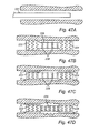
- Fig. 1 shows one embodiment of a device for reshaping a cardiac valve, which may be used for treatment of mitral annulus dilatation.
- the device shown in Fig. 1 being in an elongate and non-activated state of shape K, comprises a shape- changing member in the form of a shape memory metal thread 20, a delay means in the form of a resorbable sheath 21 enclosing the shape memory metal thread 20 for holding it in a straightened state of shape, and preferably self-expandable stents 22 and 23 located at the opposite ends of the device.
- the device may include one or more additional shape memory metal threads, e. g. if a stronger shortening force is desired.
- the shape-changing member in this embodiment in the form of the shape memory metal thread 20, may consist of or at least include Nitinol, or some other similar material which has a memory of an original shape as illustrated in Fig. 2 , and can be temporarily forced into another shape, e. g. as illustrated in Fig. 1 .
- Nitinol is an alloy composed of nickel (54-60%) and titanium. Small traces of chromium, cobalt, magnesium and iron may also be present in Nitinol.
- the material of the shape-changing member does not have to be a metal.
- Other materials such as Shape Memory Polymers (SMP) could be used as shape memory material as well.
- SMP Shape Memory Polymers
- the shape-changing material does not have to be a shape memory material. Any superelastic material would function in most cases.
- stainless steel and other metals may also be forced into a non-preferred state of shape by means of a resorbable restraining means.
- the delay means is in this embodiment in the form of the resorbable sheath 21.
- This resorbable sheath 21 is made of a material which is resorbable by the surrounding blood and tissue when applied in a human body and has the required stability and bending properties.
- Examples of usable resorbable materials from which the delay means may be made, or that are at least included, are PDS (polydioxanon), Pronova ® (polyhexaflouropropylen-VDF), Maxon ® (polyglyconat), Dexon ® (PGA, polyglycolic acid), Vicryl ® (polyglactin), PLA (polylactic acid), PDLLA (polydexolactic acid), PLLA (pololevolactic acid), starch, different kinds of sugar, butyric acid, collagen, and collatamp.
- PDS polydioxanon
- Pronova ® polyhexaflouropropylen-VDF
- Maxon ® polyglyconat
- Dexon ® PGA, polyglycolic acid
- Vicryl ® polyglactin
- PLA polylactic acid
- PDLLA polydexolactic acid
- PLLA polyolevolactic acid
- starch different kinds of
- the release of the shape-changing forces of the shape-changing member may be delayed for a desired period of time.
- design parameters such as the thickness of the resorbable material may be set so that the change of shape is delayed as long as desired.
- the delay time may vary from e. g. a few days up to several years depending on the application.
- the thickness of the delay means is chosen so that the time needed for the surrounding blood and tissue in the coronary sinus 24 to resorb the delay means enough for the device to enter its second shorter state of shape K'is adapted to the time needed for the ends of the device to be fixed within the coronary sinus 24.
- the thickness of the delay means may vary along the device, so that the order in which different parts of the device are released by the delay means may be controlled.
- the delay means may be flexible enough to follow the curves in e. g. a vessel, but has a stiffness, here especially in its radial direction, which withstands the shape-changing force of the shape-changing member.
- the shape- changing member of the device will strive towards its original, here curved, shape according to Fig. 2 , but is restrained by the delay means.
- the self-expandable stents 22 and 23 may be of conventional type with an elastic cylindrical unit, made of e. g. Nitinol, in an opened zigzag configuration.
- the self-expandable stents 22 and 23 may be provided with hook means (not shown), in the form of protrusions extending from the outer surface of the stents 22 and 23. These hook means are arranged to dig into the wall of the coronary sinus 24 when the self-expandable stents 22 and 23 expand against the wall, and thereby facilitate and enhance the fixing of the self-expandable stents 22 and 23 into the wall of the coronary sinus 24.
- Fig. 1a shows an embodiment according to the invention of a device for reshaping a cardiac valve.
- the shape memory metal thread 20 is replaced by a scissors-shaped shape-changing member 20a.
- the resorbable sheath 21 may then be replaced by resorbable threads 21 a.
- self-expandable stents 22a and 23a are located at the opposite ends of the device.
- the state of shape corresponding to K' in Fig. 2 of the device shown in Fig. Ia is shown in Fig. 2a .
- the elongate device in Fig. 1 (or the one in Fig. Ia) is locked onto a stent insertion device (not shown) so that the self-expandable stents 22 and 23 (or 22a and 23a) are held in a crimped, non-expanded state. Thereafter, the stent insertion device with the elongate device locked thereon is pushed through the introduction sheath and the venous system to the coronary sinus 24 riding on the guiding wire. After having obtained an exact positioning of the elongate device in the coronary sinus 24, as illustrated in Fig. 3 where the mitral valve annulus 25 and the mitral valve 26 having a central gap 27 are shown, the stent insertion device is removed.
- the self-expandable stents 22 and 23 (or 22a and 23a) will grow into the wall of the coronary sinus 24 while at the same time the resorbable sheath 21 (or restraining threads 21 a) will be resorbed by the surrounding blood and tissue in the coronary sinus 24, as schematically illustrated in Fig. 4 .
- the resorbable sheath 21 (or resorbable threads 21 a) has been resorbed to such a degree that it cannot hold the shape memory metal thread 20 (or the scissors-shaped member 20a) in its straightened state of shape any longer, the self-expandable stents 22 and 23 (or 22a and 23a) will be properly fixed into the wall of the coronary sinus 24 as a result of the normal healing process which always occurs after positioning a stent in a blood vessel. Then the shape memory metal thread 20 (or the scissors-shaped member 20a) retracts and the device is transformed to its activated shorter state of shape K', as illustrated in Figs 2 and 5 (corresponding to Fig. 2a ). This shortening of the device makes it bend towards the mitral valve annulus 25, moving the posterior part thereof forward. This movement reduces the circumference of the mitral valve annulus 25 and thereby closes the central gap 27.
- the device may be positioned by catheter technique or by any other adequate technique. It may be heparin- coated so as to avoid thrombosis in the coronary sinus 24, thus reducing the need for aspirin, ticlopedine or anticoagulant therapy. At least parts of the device may contain or be covered with drugs like Tacrolimus, Rappamycin or Taxiferol to be delivered into the tissue to prohibit excessive reaction from surrounding tissue. At least parts of the device may be covered with or contain VEGF (Vascular Endothelial Growth Factor) to ensure smooth coverage with endothelial cells.
- VEGF Vascular Endothelial Growth Factor
- the activated state of shape K'could be a bended shape instead of a shorter shape, whereby the desired closure of the central gap 27 still may be achieved.
- the basic inventive idea of the present invention which solves the problem with insufficient fixing of the implantable device before the shape of it is changed, is to delay the reshaping of the device by means of a (resorbable) delay means being comprised in the device itself, and thereby allow the device to grow fixed in body tissue by means of natural healing processes.
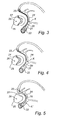
- Figs 6 to 9 show the principle of delayed shortening.
- a shape-changing member 1 here in the form of a thread 1, made of or at least in part including a shape memory material is shown having a curved shape.
- This shape is the original shape that the shape-changing member 1 "remembers"and will assume when the temperature thereof passes a certain threshold, e. g. exceeds 30 C.
- Fig. 7 shows the shape-changing member 1 of Fig. 6 having been straightened by stretching to a substantially straight shape.
- Fig. 8 illustrates a device which is in its non- activated state of shape A. More specifically, by covering the stretched and straight shape-changing member 1 in Fig. 7 with a delay means 2, here in the form of a tube 2 having a sufficiently small inner cross-section, the stretched shape of the shape-changing member 1 can be maintained even when the device is implanted into a human body and the temperature of the shape-changing member 1 thus exceeds the threshold, e. g. 30 C.
- a delay means 2 here in the form of a tube 2 having a sufficiently small inner cross-section
- the delay means 2 By manufacturing the delay means 2 from a resorbable material, the delay means 2 will be resorbed by time and the shape-changing member 1 will resume its original shape when the delay means 2 has been resorbed to such a degree or extent that it cannot restrain the shape- changing member 1 any longer, as schematically illustrated in Fig. 9 .
- the device has now"been transformed”from its non-activated long state of shape A ( Fig. 8 ), to an activated, shortened state of shape A' ( Fig. 9 ), where the device consists essentially of the shape-changing member 1 only.
- the curved thread 1 is located to the left in Fig. 9 , but, after its transformation, the thread 1 may just as well be located anywhere along the remaining parts of the tube 2.
- the device in Fig. 8 may be manufactured in the following way, which is also applicable for manufacturing all except the ends of the embodiment of a device shown in Fig. 1 .
- the thread 1 of a shape memory material e. g. with the shape illustrated in Fig. 7
- the thread 1 is programmed to remember the shape illustrated in Fig. 6 by being held in that shape while at the same time being heated to a temperature above said threshold.
- the thread 1 Upon cooling, beneath the threshold temperature, e. g. down to room temperature, the thread 1 will become more flexible and may more easily be deformed into its previous shape shown in Fig. 7 .
- the thread 1 is covered by the resorbable tube 2, e. g. by threading the tube 2 onto the thread 1 or by forming the tube 2 around the thread 1.
- a shape-changing member of a memory material is first held in a "preferred” state of shape while being heated above a threshold temperature, and then cooled beneath the threshold temperature so that it can easily be deformed into its previous "non-preferred” state of shape. Thereafter, the now “programmed” shape-changing member is "locked” in said non-preferred state of shape by a delay means in such a way that the delay means will obstruct the shape-changing member from resuming its preferred state of shape when being heated again, e. g. in a human body.
- the inner radius of the tube 2 must not necessarily be so small that the shape-changing member in the form of the thread 1 cannot move at all in the radial direction. Hence, there may be a small radial play in which the shape-changing member 1 can move without consequently being able to change the length of the device to any larger extent.
- the device in Fig. 8 may also be manufactured with essentially no play between the shape- changing member 1 and the inner side of the delay means 2, possibly also with a pretension or bias force from the delay means 2 acting on the shape-changing member 1.
- Fig. 10 shows a shape-changing member 3, here in the form of a thread 3 of a shape-memory material, having a straight original shape.
- Fig. 11 shows the shape-changing thread member 3 of Fig. 10 when having been folded to a curved shape.
- Fig. 12 illustrates a device according to the basic inventive idea comprising a thread 3 as illustrated in Fig. 11 , where the device is in its non-activated state of shape B.
- a delay means 4 in the form of a tube 4 of a resorbable material, the curved shape B can be maintained even when the device is implanted into a human body and strives towards its original straight shape.
- the delay means 4 is resorbed by time and consequently the shape-changing member 3 will be released to resume its original straight shape B'.
- the device has now been transformed from its non-activated short state of shape B ( Fig. 12 ) to an activated, elongated state of shape B' ( Fig. 13 ).
- the length of the shape- changing member 1; 3 is substantially unchanged by the transformation, whereas the shape of the shape-changing member 1; 3 is changed so that the length of the device is changed.
- Figs 14 to 25 show some different devices according to the basic inventive idea.
- Fig. 14 shows a device being an alternative arrangement of a device for delayed elongation as compared to the device shown in Fig. 12 .
- the delay means comprises resorbable crosslinks 6 which hold the shape- changing member 5 in its curved state of shape and thus the device in its non-activated short state of shape C.
- Resorbable crosslinks 6 may also be combined with a tube 4 ( Fig. 12 ).
- Fig. 15 shows a device in its non-activated elongate state of shape D.
- the shape-changing member 7 is scissors-shaped.
- a delay means 8 in the form of a tube 8 of resorbable material holds the shape-changing member 7 in a stretched, elongated state of shape and, thus, also the device in its elongate state of shape D.
- the delay means 8 has been sufficiently resorbed, the scissors-shaped shape-changing member 7 will resume its original non-stretched shape and the device is transformed to its activated short state of shape D' ( Fig. 16 ).
- Fig. 15a shows an alternative device where the tube 8 in Fig. 15 is replaced by a delay means in the form of resorbable threads 8a.
- the delay means 8a holds the scissors-shaped shape-changing member 7a in a stretched, elongate state of shape and, thus, the device in a state of shape corresponding to D in Fig. 15 .
- Fig. 16a when the delay means 8a is cut off by means of resorption, the shape-changing member 7a will resume its original non-stretched shape and the device is trans- formed to its activated short state of shape corresponding to D' in Fig. 16 .
- Fig. 17 shows a device according to the basic inventive idea in its non-activated short state of shape E.
- a scissors-shaped shape-changing member 9 of the device is held in a short state of shape by means of a delay means in the form of a resorbable thread 10, and, thereby, the whole device is held in its short state of shape E.
- the delay means 10 is cut off by means of resorption, the shape-changing member 9 will resume its original elongate shape so that the device is transformed to its activated state of shape E' ( Fig. 18 ).
- Fig. 19 shows a device according to the basic inventive idea comprising a shape-changing member in the form of a coil 11 of a shape-memory material having been stretched and arranged in a delay means in the form of a tube 12 of resorbable material. The device is then in its non-activated state of shape F. When the delay means 12 has been sufficiently resorbed, the shape-changing member 11 will resume its original shorter and wider shape as shown in Fig. 21 , and the device is transformed to its activated state of shape F'.
- the tube 12 in Fig. 19 is replaced by a resorbable rod 13 provided with grooves 13a in which a coil 11 is initially wound.
- the winding of the coil 11 in the grooves 13a obstructs the coil 11 from resuming its original shape ( Fig. 21 ) and, hence, the device is held in its non-activated state of shape G by the rod 13, as illustrated in Fig. 20a.
- the rod 13 By resorption of the rod 13 in e. g. a human body, the shape- changing force of the coil 11 is released and the device is transformed to its activated state of shape G'as shown in Fig. 21 .
- a coil 14 is wound around a resorbable rod 15.
- the shape-changing forces of the coil 14 will be released so that the coil 14 resumes an original elongate shape, as shown in Fig. 23 , whereby the device is transformed from its non-activated state of shape H to its activated state of shape H'.
- Fig. 24 shows a device according to the basic inventive idea in the form of a patch for closing or obstructing openings, e. g. in the heart of a human or animal body.
- the patch has a shape-changing member 16 comprising a grid matrix formed by threads made of memory material such as Nitinol or SMP.
- the threads may be covered individually by biocompatible material such as PTFE or dacron to fill in the gaps between the threads, e. g. in the way shown in Fig. 26 with threads 28 and biocompatible material 29.
- the patch in Fig. 24 further comprises a frame 17 for anchoring the patch in the body, e. g. by means of sutures.
- the frame may be made of any biocompatible material, such as PTFE or dacron.
- the threads may be spread apart, creating a central opening 16a in the patch.
- the cone is advanced until a delay means 18 in the form of a separate ring 18 of a resorbable material, initially positioned on the cone, is positioned in the opening 16a.
- the cone is then drawn back and the ring 18 is left in the opening 16a, restraining the elastic threads in such a way that the central opening 16a in the patch is maintained.
- the patch 24 shows the patch in its non-activated state of shape I with the ring 18 positioned centrally. After implant and sufficient resorption of the restraining ring 18 and after a specified period of time, the central opening in the patch is closed and the patch is activated.
- Fig. 25 shows an alternative device according to the basic inventive idea in the form of a patch for closing openings.
- the patch may be constructed by attaching delay means 19 in the form of resorbable threads or bands 19 to the top of a sharp cone and down along the sides of the cone, advancing the cone through the middle of the patch so that the elastic threads 16 are spread out and thus an opening 16a in the patch is created, and fastening one end of each band to the frame 17 on one side of the patch and the other end of each band 19 to the frame 17 on the other side of the patch, so that each band 19 encircles the opening.
- the bands 19 could be placed at regular intervals along the circumference of the opening so that they expand a substantially circular hole in the middle of the patch.
- the single shape-changing thread in Figs 6 to 14 may be replaced by several threads or by one or more bands.
- the scissors-shaped members 7 and 9 in Figs 15 to 18 may be multiplied so as to form a scissor-shaped area, which in turn may be shaped into different forms.
- the single tube in Figs 8 , 12 , 15 and 19 may be slotted or may be divided into several tube segments.
- a delay means may also be provided in the form of resorbable glue, which holds parts of the shape-changing member together and in that way delay the change of shape of the device.
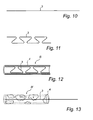
- Fig. 26 shows one possible arrangement of a part of a contractable area according to the basic inventive idea.
- the contractable area comprises a shape-changing member in the form of a grid matrix of shape memory metal threads 28 covered by a delay means in the form of a fabric of a resorbable material (it should be noted that Fig. 26 was previously used to illustrate how the threads of the patches of Figs 24 and 25 may be covered with biocompatible material).
- the fabric comprises resorbable bands 29 which have been weaved together to form an area. Each of the resorbable bands 29 is solid except for a cylindrical hollow space in which a thread 28 is located, just like the thread 1 is located inside the tube 2 in Fig. 8 .
- the bands 29 restrain the threads 28 from being folded to their original curved shapes as long as the fabric 29 is not resorbed.
- each band 29 must not necessarily be cylindrical. In fact, if the width of each band 29 is small enough as compared to the curves that the threads 28 will assume when being"activated"as a result of the bands 29 being resorbed, the bands 29 may be hollow.
- the contractable area in Fig. 26 may be manufactured by threading a thread 28 of a memory material into each resorbable band 29 and then weaving the bands 29 with threads 28 together to form the fabric as illustrated in Fig. 26 .
- Another possible way of making a contractable area would be to arrange threads or bands of a memory material in a grid matrix and to fix the threads or bands together with resorbable crosslinks. The resorbable crosslinks would then restrain the threads or bands from being folded as long as enough resorbable material in the crosslinks is left unresorbed.
- the basic inventive idea opens up for new possibilities within many medical applications.
- the basic inventive idea would for example be useful where openings of human, or animal, organs or other structures need to be opened or closed slowly. For instance, when an opening between the left and right side of the heart is present, an immediate closure of the opening could be dangerous, whereas a slower closure would be tolerated.
- One such application would be a device designed to shorten or lengthen a human or animal structure in one or more dimensions. The device would then have time to heal into the body structure before shape-changing forces are released and force the body structure to slowly change its shape.
- the basic inventive idea would be useful when it comes to tooth-regulation and lengthening of the maxilla and/or mandibula, i. e. the upper and lower jaws.
- An example within the area of urology surgery is lengthening of a penis.
- a device made of three segments could be designed, where the distal ends of the device first are allowed to grow into the tissue. After fixation of the two ends of the device in the penis tissue, the mid portion which temporarily has been restrained by means of a resorbable material as described above will be released and the mid portion of the device will grow in length.
- One specific capacity of a human or animal body is to allow slow deformation of organs or tissues by compensatory tissue adaptation. A penis would therefore grow slowly to a predetermined length.
- a sequential effect of shape-changing forces could also be provided, i. e. change of shape could occur in two or several steps as a result of resorbable material releasing the shape-changing forces in predetermined steps.
- a part or parts of a device could first heal into a body structure and secondly the desired shape-changing effects could be released.
- a substantial advantage of the basic inventive idea is that a change of shape is allowed to be made slowly so that body tissues have time to adapt.
- Another medical application of particular interest which could be improved by using the basic inventive idea, is treatment of pathological alveolar sac growth. Some background of this disease will be given next.
- COPD chronic obstructive pulmonary disease
- Emphysema causes irreversible lung damage by weakening and breaking the air sacs within the lungs. Further, sick air sacs sometimes grow unrestrainedly and repress smaller air sacs, resulting in lack of oxygen and by time death. This disease is hard to treat. At present, surgical treatment of dilated air sacs involves cutting them away, but this treatment gives no long-term effect since a new air sac will soon start to grow.
- a contractable area may be formed into a contractable sheet for treatment of alveolar sac growth, e. g. emphysematic pulmonary diseases.
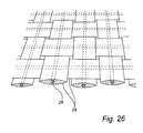
- Figs 27 and 28 show the use of a device according to the basic inventive idea for treatment of alveolar sac growth.
- a contractable sheet 34 in its non-activated state of shape M is rolled up on a catheter 35, introduced between ribs 36 into the pleural cavity (the space between the pleura of the lung and the pleura of the chest wall), and placed upon the lung 38 surface to be treated.
- the contractable sheet 34 may also be inserted into the body by means of open surgery or by means of endoscopic surgery and positioned on an organ surface.
- the sheet 34 is then rolled out over the lung 38 and the catheter 35 is removed.
- the sheet 34 is arranged to grow fixed to the lung surface so that subsequent contraction of the sheet 34, as a result of the resorbable material of the sheet 34 being resorbed, causes the sheet 34 to compress the lung 38 by means of a force of the shape memory metal threads in the sheet 34.
- bullae and areas of enlarged alveolar sacs may be shrunk or eliminated and further pathological growth of alveolar sacs may be prevented.
- the contractable sheet 34 contracts in two directions, one approximately vertical and one approximately horizontal.
- the sheet 34 could also be designed to contract in one direction only, e. g. the most horizontal one, or contract in a circular mode, and still be able to shrink bullous areas and prevent alveolar sacs from growing.
- a device for treatment of pathological lung growth is implantable into the body of an organism and comprises an elastic contractable member being arranged to enclose at least part of the lung of the organism, and a delay means being arranged to delay contraction of the contractable member when the device is implanted in the body of the organism by counteracting the contraction during resorption of the delay means by the surrounding body of the organism.
- a basic advantage of this device is that the device, since said contractable member is elastic, can be inserted into the body using catheter-guided techniques. Hence, less invasive treatments can be provided.
- Another advantage which comes both from the elasticity and the delayed contraction, is that the device can be inserted by means of catheter-guided techniques even if said contractable member comprises a large area. This is due to the fact that the substantially elastic device at the insertion can be rolled up on a catheter and then be unfolded to enclose said organ.
- the device After a period of time after the surgical or percutaneous insertion, the device will start to contract as a result of the delay means being resorbed. The contraction will then make the device enclose the organ tight and apply a restraining force which holds back the growth of the organ. Since the implanted device applies a continuous restraining force to the organ, more long-term effects can be achieved in treatment of growing body organs. It is to be noted that if the contraction of the device would not have been delayed, it would have been very difficult to roll up the device on a catheter and then unfold it round the organ.
- said contractable member comprises a shape memory material, e. g. Nitinol.
- a method for treatment of pathological lung growth comprises the steps of inserting a restraining device into the body of an organism, enclosing the lung of the organism with the restraining device, compressing said restraining device by means of a contractable member of said restraining device, and delaying said compression by a resorbable delay means.
- the method may be used for treatment of bullous emphysema. It may also be used for treatment of alveolar sac growth.
- a device according to the basic inventive idea may be fixed in body tissue by other means in combination with or instead of the healing process allowed by the delaying of the change of shape.
- fixing of a device according to the basic inventive idea may as well be accomplished for example by means of suturing, gluing, clipping or using hooks. These means of fixation would permit a better healing in of the device in the tissue and also prohibit dislocation while healing in.
- the present invention takes advantage of the position of the coronary sinus being close to the mitral annulus. This makes repair possible by the use of current catheter-guided techniques by deploying one element in the coronary venous vasculature that applies a load to, and reshapes, the adjacent posterior portion of the mitral annulus.
- the coronary veins drain blood from the myocardium to the right atrium.
- the smaller veins drain blood directly into the atrial cavity, and the larger veins accompany the major arteries and run into the coronary sinus which substantially encircles the mitral orifice and annulus.
- the coronary sinus runs in the posterior atrioventricular groove, lying in the fatty tissue between the left atrial wall and the ventricular myocardium, before draining into the right atrium between the atrial septum and the post-Eustachian sinus.
- FIG. 29 is a cross-sectional view through the heart area of posterior atrioventricular groove 101, which is filled with fatty tissue. It shows posterior leaflet 102 of the mitral valve and adjoining parts 103,104 of the atrial myocardium and the ventricular myocardium. Coronary sinus 105 is shown close to mitral annulus 106 and behind attachment 107 of posterior leaflet 102. Since coronary sinus 105 substantially encircles mitral annulus 106, a reduction of the radius of curvature of bent coronary sinus 105 also will result in a diameter and circumference reduction of mitral annulus 106.
- coronary sinus 105 may approach within 5-15 mm of the medial attachment of posterior leaflet 102 of the mitral valve. Preliminary measurements performed at autopsies of adults of normal weight show similar results, with a distance of 5.3 ⁇ 0.6 mm at the medial attachment and about 10 mm at the lateral aspect of posterior leaflet 102.
- the circumference of coronary sinus 105 was 18.3 ⁇ 2.9 mm at its ostium (giving a sinus diameter of the septal aspect of the posterior leaflet of 5.8 ⁇ 0.9 mm) and 9.7 ⁇ 0.6 mm along the lateral aspect of posterior leaflet 102 (corresponding to a sinus diameter of 3.1 ⁇ 0.2 mm).
- a devices for treating mitral insufficiency wherein the circumference of the mitral valve annulus is reduced when the device is deployed and/or actuated in at least a portion of the coronary sinus.
- Devices for treatment of mitral insufficiency may comprise one or more components suitable for deployment in the coronary sinus and adjoining coronary veins.
- the device may be configured to bend in-situ to apply a compressive load to the mitral valve annulus with or without a length change, or may include multiple components that are drawn or contracted towards one another to reduce the circumference of the mitral valve annulus.
- Any of a number of types of anchors may be used to engage the surrounding vein and tissue, including hooks, barbs, flanges, partial or completely through-wall tee structures, or biological anchoring. Where multiple components are provided, reduction of the mitral valve annulus may be accomplished during initial deployment of the device, or by biological actuation during subsequent in-dwelling of the device.
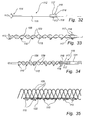
- a device that experiences shortening during deployment is described as comprising an elongate body 108 made of memory metal, e. g. Nitinol, or other similar material which has a memory of an original shape, illustrated in FIG. 31 , and which can be temporarily forced into another shape, illustrated in FIG. 30 .
- Elongate body 108 comprises one, two or more memory metal strings 109 of helical or other shape so as to fit together and be able of to permit the movements described below.
- plurality of hooks 110 are fastened so as to extend radially out therefrom. Hooks 110 are covered by a cover sheath 111 in FIG. 30 .
- Elongate body 108 is forced into a stretched or extended state by means of stabilizing instrument 112 shown in FIG. 32 .
- Instrument 112 has two arms 113 at distal end 114 of rod 115 and locking means 116 at proximal end of rod 115. The distance between the ends of rod 115 corresponds to the desired length of elongate body 108 when being inserted into coronary sinus 105.
- Locking means 116 has two locking knobs 117, which are pressed radially outwards from rod 115 by two spring blades 118.
- elongated body 108 can be pushed over rod 115 of stabilizing instrument 112, then stretched between arms 113 and knobs 117, and finally locked in its stretched state on stabilizing instrument 112 between arms 113 and knobs 117, as illustrated in FIG. 33 .
- Rod 115 may be a metal wire which is relatively stiff between distal end 114 and locking means 116 but still so bendable that it will follow the shape of coronary sinus 105. Proximally of locking means 116 the metal wire of stabilizing instrument 112 is more pliable to be able to easily follow the bends of the veins.
- the above-described elongate body 108 is positioned in the coronary sinus 105 in the following way:
- Elongate body 108 is locked onto stabilizing instrument 112, as shown in FIG. 33 , and introduced into long cover sheath 111 of synthetic material. This aggregate is then pushed through the introduction sheath and the venous system to coronary sinus 105 riding on the guiding wire.
- cover sheath 111 is retracted to expose elongate body 108 within coronary sinus 105. This maneuver allows hooks 110 on elongate body 108 to dig into the walls of coronary sinus 105 and into the heart.
- Elongate body 108 is still locked on to stabilizing instrument 112 such that hooks 110 engage the walls of coronary sinus 105 in the stretched or extended state of elongate body 108.
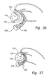
- Catheter 121 shown in FIG. 34 , is pushed forward on the guiding wire and rod 115, to release elongate body 108 from locking means 116 by pressing spring blades 118 toward rod 115.
- This movement releases knobs 117 as well as arms 113 from engagement with elongate body 108, which contracts elongate body 108 as illustrated in FIG. 37 , thereby shortening the radius of curvature of coronary sinus 105.
- mitral valve annulus 106 shrinks moving the posterior part thereof forward (shown by arrows in FIG. 37 ). This movement reduces the circumference of mitral valve annulus 106 and thereby closes central gap 120.
- FIG. 35 illustrates a part of an arrangement of wires 109 and hooks 110 along a peripheral part of elongate body 108, whereby elongate body 108 will be asymmetrically contracted resulting in a bending thereof when interconnecting parts 122 of at least some of hooks 110 are shortened to an original shape.
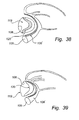
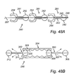
- FIGS. 38 and 39 illustrate an alternative embodiment of an elongate body 108' which does not experience shortening during deployment.
- Elongate body 108' comprises a solid wire in the shape of an open U-shaped ring that will engage the wall of coronary sinus 105 most adjacent to mitral valve annulus 106 when inserted into coronary sinus 105.
- Elongate body 108' consists of a memory metal material which when reverting to its original shape will bend as illustrated in FIG. 39 .
- the return of open ring 108' to its original shape may be initiated in several ways, as is obvious to the man skilled in the art.
- proximal stent section includes a flange that can be deployed to abut against the coronary ostium.
- Apparatus 156 comprises device 158 disposed within delivery sheath 160.
- Device 158 comprises proximal stent section 162 joined to distal stent section 164 via wire 166 and cinch mechanism 167.
- Proximal and distal stent sections 162 and 164 illustratively are self-expanding stents, but alternatively may comprise balloon expandable stents, coiled-sheet stents, or other type of stent.
- Stents sections 162 and 164 are disposed within delivery sheath 160 with a distal end of push tube 168 contacting the proximal end of proximal stent section 162.
- Proximal stent section 162 comprises deployable flange 169.
- Deployable flange 169 is initially constrained within delivery sheath 160, as shown in FIG. 40A , and preferably comprises a shape memory material, e. g. , Nitinol, so that flange 169 self-deploys to a predetermined shape upon retraction of delivery sheath 160.
- Wire 166 and cinch mechanism 167 may comprise a combination of wires and eyelets as described in accordance with any of the embodiments in the above- incorporated reference, or any other arrangement that permits the wire to be tightened and locked into position, as will be apparent to one of ordinary skill.
- Wire 166 includes a proximal portion that remains outside of the patient's vessel for manipulation by a physician, and is configured to reduce the distance between proximal and distal stent sections 162 and 164.
- Apparatus 56 is navigated through the patient's vasculature with stents sections 162 and 164 in the contracted state and into coronary sinus.
- the distal end of sheath 160 is disposed, under fluoroscopic guidance, at a suitable position within the coronary sinus, great cardiac vein, or adjacent vein.
- Push tube 168 is then urged distally to eject distal stent section 164 from within delivery sheath 160, thereby permitting distal stent section 164 to self-expand into engagement with the vessel wall, as shown in FIG. 40B .
- Delivery sheath 160 is then withdrawn proximally, under fluoroscopic guidance, until proximal stent 162 is situated extending from the coronary sinus.
- Push tube 168 is then held stationary while delivery sheath 160 is further retracted, thus releasing proximal stent section 162.
- proximal stent section 162 expands into engagement with the wall of the coronary sinus, and flange 169 abuts against the coronary ostium, as shown in FIG. 40C .
- Delivery sheath 160 (and or push tube 168) may then be positioned against flange 169 of proximal stent section 162, and wire 166 retracted in the proximal direction to draw distal stent section 164 towards proximal stent section 162.
- distal stent section 164 is drawn towards proximal stent section 162 under fluoroscopic or other type of guidance, so that the degree of reduction in the mitral valve annulus may be assessed.
- cinch mechanism 167 prevents distal slipping of the wire.
- wire 166 may include a series of grooves along its length that are successively captured in a V-shaped groove, a pall and ratchet mechanism, or other well-known mechanism that permits one-way motion.
- Catheter 60 and push tube 168 then may be removed, as shown in FIG. 40D .
- Flange 169 may comprise a substantially circular shape-memory member, as illustrated, a plurality of wire members, e. g. , manufactured using Nitinol, that self- deploy upon removal of delivery sheath 160 and abut ostium O when proximally retracted, or other suitable shape.
- proximal and distal stent sections 162 and 164 are deployed in the coronary sinus C so that flange 169 of proximal stent section 162 engages coronary ostium O.
- Distal stent section 164 is disposed at such a distance apart from proximal stent section 162 that the two stent sections apply a compressive force upon mitral valve 170 when wire 166 and cinch 167 are actuated.
- cinch 167 is actuated from the proximal end to reduce the distance between proximal and distal stent section 162 and 164, e.g., as described hereinabove.
- wire 166 and cinch mechanism 167 are actuated, distal stent section 164 is pulled in a proximal direction and proximal stent section 162 is pulled in a distal direction until flange 169 abuts coronary ostium O.
- the reduction in distance between proximal and distal stent sections 162 and 164 reduces the circumference of mitral valve annulus 171 and thereby closes gap 172.
- Flange 169 provides a secure anchor point that prevents further distally- directed movement of proximal stent section 162, and reduces shear stresses applied to the proximal portion of the coronary sinus.
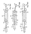
- Device 190 comprises proximal stent section 192 coupled by wire 194 and cinch mechanism 195 to distal anchor 196.
- Proximal stent section 192 may include flange 193.
- Optional coil section 198 extends distally from proximal stent section 192 to distal anchor 196, and serves to distribute compressive forces created by wire 194 to a larger area of the venous vessel wall.
- Curved stylet 202 preferably comprises a shape memory alloy capable of being straightened, but adopting a curved shape when extended beyond a distal end of delivery sheath 206.
- Curved stylet 202 includes sharpened distal tip 201 capable of piercing the left ventricular myocardium, and is disposed in lumen 205 of delivery sheath.
- Push wire 204 is slidably disposed in lumen 203 of curved stylet 202, and may be advanced distally to eject distal anchor 196 into the left ventricular myocardium or the left ventricle.
- distal anchor 196 comprises a Tee-shaped bar to which wire 194 is coupled.
- Optional coil section 198 also may be coupled to distal anchor 196, and is contracted around curved stylet 202 when device 190 is loaded into delivery sheath 206.
- Distal anchor 196 is disposed within lumen 203 of curved stylet so that wire 194 and coil section 198 exit through lateral slot 207 in the stylet 202.
- Push wire 204 is disposed in lumen 203 of stylet 202 abutting against the proximal face of distal anchor 196.
- device 190 is shown loaded into delivery apparatus 200.
- Delivery apparatus 200 has been disposed in the coronary sinus using conventional guidance and visualization techniques. The distal end of delivery apparatus 200 is advanced into the coronary venous vasculature to a desired location, and then stylet 202 is advanced distally beyond the end of delivery sheath 206, thereby causing the stylet to regain its curved shape. Further advancement of stylet 202 causes the distal end of the stylet to pierce the coronary vein and extend into the left ventricular myocardium. Push rod 204 is then advanced distally to eject distal anchor 196 into the myocardium, or within the left ventricle, as shown in FIG. 42B .
- proximal stent section 192 may be deployed simply by retracting delivery sheath 206, because distal anchor 196 and wire 194 will prevent further proximal movement of proximal stent section 192. In any event, when proximal stent section 192 is released from delivery sheath 206, it self-expands to engage the vessel wall while flange 193 contacts the coronary ostium, as shown in FIG. 42C .
- proximal wire 194 extends through lumen 205 of delivery sheath 206 and may be manipulated by a physician. As in the previous embodiment, once the proximal stent section is deployed, wire 194 may be pulled proximally, with cinch mechanism 195 taking up any slack. The distance between distal anchor 196 and proximal stent section 192 may therefore be reduced a desired amount, causing a corresponding reduction in the circumference of the mitral valve annulus. Optional coil section 198, if present, assists in redistributing the compressive forces applied by wire 194 to the interior surface of the venous vessel.
- device 190 of FIGS. 42 is illustrated in a deployed state to treat mitral insufficiency.
- Flange 193 is deployed abutting coronary ostium O, e. g. , within right atrium A.
- Proximal stent section 192 and optional coil section 198 are deployed within the coronary sinus and great cardiac vein C.
- Distal anchor 196 is disposed within myocardium M, or alternatively, may extend into the left ventricle or another suitable region, as will be obvious to those skilled in the art. It should further be appreciated to those skilled in the art that while anchor 196 is illustrated as a cylindrical bar, it may comprise square, circular or other configurations, e.g., a plurality of barbs.
- the proximal end of wire 194 extends through cinch mechanism 195 and is manipulated to impose tension on wire 194, thereby reducing the distance between proximal stent section 192 and distal anchor 196. This in turn reduces the circumference of coronary sinus C accordingly, as shown in FIG. 43B .
- apparatus 200 is removed from the patient's vessel.
- distal anchor 196 is expected to reduce the shear stress imposed on coronary sinus C relative to the use of a proximal stent section alone as described for the embodiment of FIGS. 40 and 41 .
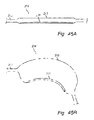
- device 210 comprises a balloon expandable stent 212, which may be tapered along its length.
- Stent 212 is disposed on the distal region of balloon catheter 214, which is capable of assuming a curved shape when inflated.
- stent 212 and balloon catheter 214 are disposed in the patient's coronary sinus through the coronary ostium.
- balloon catheter 214 is inflated via inflation lumen 213 to expand balloon catheter 214 to its predetermined curved shape. Inflation of balloon catheter 214 causes stent 212 to be plastically deformed in accordance with the predetermined shape of balloon catheter 214.
- the degree of mitral valve regurgitation may be monitored during the step of inflating balloon catheter 214, so that stent 212 applies only so much compressive load on the mitral valve annulus as is required to reduce the regurgitation to a clinically acceptable level.
- Balloon catheter 214 is removed from the patient's vessel upon completion of the stenting procedure.
- the balloon catheter 214 has proximal and distal ends, and comprises balloon 215, and inflation lumen 213 and guidewire lumens, as is per se known.
- Balloon catheter 214 includes an anchor element 216, such as a strand of wire, affixed to its interior surface, so that when the balloon catheter 214 is inflated, it adopts a predetermined shape, as shown in FIG. 45B .
- anchor element 216 such as a strand of wire
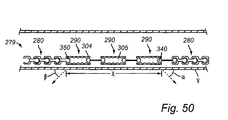
- FIGS. 46A-47C another alternative embodiment of a device for treatment of mitral insufficiency is described, in which the device comprises proximal and distal stent sections joined by a central section capable of undergoing foreshortening.
- Device 220 comprises proximal stent section 222, distal stent section 224 and central section 226. Further, device 220 includes one or more biodegradable structures 228, such as sutures, disposed on central section 226 to retain that section in the contracted shape for a predetermined period after placement of the device in a patient's vessel.
- biodegradable structures 228, such as sutures disposed on central section 226 to retain that section in the contracted shape for a predetermined period after placement of the device in a patient's vessel.
- FIG. 46A device 220 is depicted with its proximal and distal stent sections radially expanded, but with central section 226 restrained in the contracted position.
- FIG. 46B depicts device 220 with all three stent sections contracted as if disposed in a delivery catheter.
- FIG. 46C shows all three stent sections fully expanded.
- all three sections are integrally formed from a single shape memory alloy tube, e.g., by laser cutting.
- the stent sections then are processed, using known techniques, to form a self- expanding unit.
- Device 220 has a contracted delivery configuration, wherein the device is radially contracted within a delivery sheath, and a deployed expanded configuration, wherein at least the proximal and distal sections self-expand to engage the interior surface of the coronary sinus or adjoining veins.
- the biodegradable structures may be designed to biodegrade simultaneously or at selected intervals.
- this embodiment permits the proximal and distal stent sections 222 and 224 to become biologically anchored in the venous vasculature before those sections are drawn together by expansion of central section 226 to impose a compressive load on the mitral valve annulus.
- device 220 is loaded into delivery sheath 221 and positioned within the patient's coronary sinus. The device is then ejected from the delivery sheath 121, so that the proximal and distal stent sections 222 and 224 radially expand into engagement with the vessel wall.
- central section 226 is retained in a contracted state by biodegradable structures 228, illustratively biodegradable sutures, e. g, a poly-glycol lactide strand or VICREL suture, offered by Ethicon, Inc. , New Brunswick, NJ, USA.
- the proximal and distal stent sections 222 and 224 will endothelialize, i.e., the vessel endothelium will form a layer E that extends through the apertures in the proximal and distal stent sections and causes those stent sections to become biologically anchored to the vessel wall, as depicted in FIG. 47C .
- This phenomenon may be further enhanced by the use of a copper layer on the proximal and distal stent sections, as this element is known to cause an aggressive inflammatory reaction.
- biodegradable structures 228 that retain central section 226 in the contracted state will biodegrade.
- the self- expanding force of the central section will cause the biodegradable structures to break, and release central section 226 to expand.
- central section 226 is designed to shorten as it expands radially, it causes the proximal and distal stent sections 222 and 224 of device 220 to be drawn towards one another, as shown in FIG. 47D .
- the compressive force created by expansion of central section 226 thereby compressively loads, and thus remodels, the mitral valve annulus, as depicted.
- biodegradable structures 228 may be designed to rupture simultaneously, or alternatively, at selected intervals over a prolonged period of several months or more. In this manner, progressive remodeling of the mitral valve annulus may be accomplished over a gradual period, without additional interventional procedures. In addition, because the collateral drainage paths exist for blood entering the coronary sinus, it is possible for the device to accomplish its objective even if it results in gradual total occlusion of the coronary sinus.
- apparatus 280 comprises a plurality of interlocking segments 281.
- Each interlocking segment 281 preferably comprises a proximal section having socket 284, a distal section having ball 282, and a central section 283 extending therebetween.
- Each interlocking segment 281 further comprises lumen 285 configured to permit cinch wire 287 to pass through lumen 285.
- Cinch wire 287 having proximal and distal ends preferably comprises ball 288 affixed to the distal end so that ball 288 engages a distalmost interlocking segment 281 when retracted proximally. The retraction of cinch wire 287 enables a ball 282 to interlock with a socket 284 of an adjacent segment 281.
- Apparatus 280 of FIG. 48A preferably is used in combination with apparatus 290 of FIG. 48B .
- Apparatus 290 comprises proximal ball segment 302, distal ball segment 300, and connecting segment 304 having a plurality of sockets 305 separated by humps 309.
- Proximal ball segment 302 comprises proximal and distal ball segments 312 and 310, respectively, each having lumens extending therethrough, and hollow rod 311 extending therebetween.
- distal ball segment 300 comprises proximal and distal balls 308 and 306, respectively, each having lumens extending therethrough, and hollow rod 307 extending therebetween.
- Distal ball 310 of proximal segment 302 initially is configured to engage the most proximal socket 305 within connecting segment 304, while proximal ball 308 of distal segment 300 initially is configured to engage a distalmost socket 305.
- Proximal and distal ball segments 302 and 300 are capable of relative rotational and telescoping movement.
- Such movement may be achieved using a cinch wire configured to pass through each segment 3000 and 302, as shown in FIG. 49A .
- cinch wire 318 comprises distal ball 320 that is larger than a lumen of hollow rod 307 and is configured to abut distal ball 306 when a proximal end of cinch wire 318 is retracted proximally.
- Cinch wire 318 preferably is used in combination with push tube 316 that may stabilize or distally advance proximal segment 302.
- a range of telescoping and rotational motions between proximal and distal segments 302 and 300 may be achieved, as shown in FIG. 49B .
- a push force applied to ball 312 allows ball 310 to overcome the resistive forces provided by hump 309.
- the push force applied to ball 312 has advanced proximal segment 302 by three sockets relative to distal segment 300.
- Distal segment 300 may also be retracted with respect to proximal segment 302, e.g., by proximally retracting cinch wire 318.
- ball 308 also has been rotated at an angle, which in turn rotates distal segment 300 with respect to proximal segment 302.
- Apparatus 290 further comprises push tube 316 and wire loop 325.
- Wire loop 325 extends through a lumen within proximal and distal segments 302 and 300, then loops around the distal end of distal segment 300 and back into opening 327 of push tube 316.
- a physician then may manipulate a proximal portion of wire loop 325 to provide a range of telescoping or rotational motions between proximal and distal segments 302 and 300.
- a combination of apparatus 280 and apparatus 290 are used to provide a range of motion within vessel V, e.g., the coronary sinus.
- vessel V e.g., the coronary sinus.
- mitral insufficiency is treated by shortening the radius of curvature of the coronary sinus, which in turn applies a compressive force upon the mitral valve.
- the combination of apparatus 280 and apparatus 290 first may engage a wall of vessel V, e.g., via barbs or hooks (not shown) affixed to apparatus 280 and 290, and then the relative telescoping or rotational motion of segments may be used to bend vessel V to apply a compressive load on the mitral valve annulus.
- mitral insufficiency apparatus 279 comprises a proximal and distal section comprising apparatus 280, and a plurality of sections comprising apparatus 290 disposed therebetween.
- Cinch wire 318 and push tube 316 of FIGS. 49 preferably are used to manipulate relative rotational and telescopic motion of all of the components.
- the balls of apparatus 280 are coupled to their respective sockets, e.g., by proximally retracting cinch wire 318.
- balls 340 and 350 which connect apparatus 280 to apparatus 290 are rotated within sockets of connective segment 304 to allow apparatus 280 to be angled relative to apparatus 290 by angles a and as illustrated in FIG. 50 .
- the balls of apparatus 290 may be advanced incrementally in a longitudinal direction within sockets 305 of connective segments 304 to reduce distance X.
- reducing the distance X will apply a compressive force to the mitral valve to treat mitral insufficiency.
- the basic inventive idea provides:
Abstract
Description
- The present invention relates to a medical device for reshaping a cardiac valve. Moreover, the present invention relates to a device for treatment of mitral insufficiency and, more specifically, for treatment of dilation of the mitral annulus.
- Mitral insufficiency can result from several causes, such as ischemic disease, degenerative disease of the mitral apparatus, rheumatic fever, endocarditis, congenital heart disease and cardiomyopathy. The four major structural components of the mitral valve are the annulus, the two leaflets, the chordae and the papillary muscles. Any one or all of these in different combinations may be injured and create insufficiency. Annular dilation is a major component in the pathology of mitral insufficiency regardless of cause. Moreover, many patients have a mitral insufficiency primarily or exclusively due to posterior annular dilation, since the annulus of the anterior leaflet does not dilate because it is anchored to the fibrous skeleton of the base of the heart.
- Studies of the natural history of mitral insufficiency have found that totally asymptomatic patients with severe mitral insufficiency usually progress to severe disability within five years.
- At present the treatment of mitral annulus dilatation and other mitral insufficiencies consists of either repair or mitral valve replacements. Replacement can be performed with either mechanical or biological valves. Both methods require open-heart surgery, by the use of total cardiopulmonary by-pass, aortic cross-clamping and cardioplegic arrest. To certain groups of patients, open-heart surgery is particularly hazardous and therefore a less invasive method for repair of mitral insufficiency is desired.
- Such a less invasive method is proposed in
U. S. Patent No. 6,210, 432 , which describes a method for treatment of mitral insufficiency without the need for cardiopulmonary by-pass and opening of the chest and heart. The method uses a device comprising an elongate body having such dimensions as to be insertable into the coronary sinus, which is a vein that substantially encircles the mitral orifice and annulus and drains blood from the myocardium to the right atrium. The elongate body has two states, in a first of which the elongate body has a shape that is adaptable to the shape of the coronary sinus, and to the second of which the elongate body is transferable from said first state assuming a reduced radius of curvature. Consequently, the radius of curvature of the coronary sinus is reduced. Due to the coronary sinus encircling the mitral annulus, the radius of curvature as well as the circumference of the mitral annulus are reduced. Thus, the described method takes advantage of the position of the coronary sinus being close to the mitral annulus, which makes repair possible by the use of current catheter-guided techniques. - According to one method described in
U. S. Patent No. 6,210, 432 , a device comprising an elongate stent is used. The elongate stent includes hooks which are arranged to dig into the walls of the coronary sinus, by means of the surgeon retracting a cover sheet from the stent, in order to fix the position of the stent in the coronary sinus. A stabilizing instrument is used for keeping the elongate stent in its first state and then, after the hooks have dug into the walls, releasing it to its second state assuming a reduced radius of curvature. However, the position fixation of the elongate stent in the coronary sinus by means of the hooks might be insufficient, so that the sudden release of the contraction of the elongate stent dislocates it. This dislocation of the device might result in unsatisfactory reduction of the circumference of the mitral annulus. - According to an alternative method described in
U. S. Patent No. 6,210, 432 the device comprises three stent sections that are positioned in the coronary sinus and connected by wires. The wires may be manoeuvred from outside the vein system such that the distances between the adjacent stent sections are reduced. Also with this method there is a risk of dislocation of the device, since the surgeon might accidentally move insufficiently fixed stent sections out of their proper position while manipulating them from outside the vein system. - The mechanical valve carries the risk of thromboembolism and requires anticoagulation, with all its potential hazards, whereas biological prostheses suffer from limited durability. Another hazard with replacement is the risk of endocarditis. These risks and other valve related complications are greatly diminished with valve repair.
- Mitral valve repair theoretically is possible if an essentially normal anterior leaflet is present. The basic four techniques of repair include the use of an annuloplasty ring, quadrangular segmental resection of diseased posterior leaflet, shortening of elongated chordae, and transposition of posterior leaflet chordae to the anterior leaflet.
- Annuloplasty rings are needed to achieve a durable reduction of the annular dilation. All the common rings are sutured along the posterior mitral leaflet adjacent to the mitral annulus in the left atrium. The Duran ring encircles the valve completely, whereas the others are open towards the anterior leaflet. The ring can either be rigid, like the original Carpentier ring, or flexible but non-elastic, like the Duran ring or the Cosgrove- Edwards ring.
- Effective treatment of mitral insufficiency currently requires open-heart surgery, by the use of total cardiopulmonary bypass, aortic cross-clamping and cardioplegic cardiac arrest. To certain groups of patients, this is particularly hazardous. Elderly patients, patients with a poor left ventricular function, renal disease, severe calcification of the aorta, and those having previous cardiac surgery or other concomitant diseases would in particular most likely benefit from a less invasive approach, even if repair is not complete.
- In view of these drawbacks of previously known treatments, it would be desirable to provide a minimally invasive approach to treat mitral insufficiency, i. e., without the need for cardiopulmonary bypass and without opening of the chest and heart.
- It also would be desirable to provide a reduction of the mitral annulus using only catheter based technology.
- It further would be desirable to provide a treatment for mitral insufficiency that minimizes trauma to a patient's vasculature while using catheter based technology.
- An object of the present invention is to provide an improved medical device for reshaping a cardiac valve, as described above.
- A particular object of the invention is to provide a more secure fixation of a device for reshaping a cardiac valve.
- It is also an object of the present invention to provide a minimally invasive approach to treat mitral insufficiency, i. e. , without the need for cardiopulmonary bypass and without opening of the chest and heart.
- It is another object to provide a reduction of the mitral annulus using only catheter-based technology.
- It is also an object to provide a treatment for mitral insufficiency that minimizes trauma to a patient's vasculature while using catheter based technology.
- These and other objects are achieved by providing a device for treatment of mitral insufficiency, whereby the circumference of the mitral valve annulus is reduced when the device is deployed and/or actuated in at least a portion of the coronary sinus.
- More particularly, a device according to the present invention for reshaping a cardiac valve is elongate and has such dimensions as to be insertable into a cardiac vessel and has two states, in a first state of which the device has a shape that is adaptable to the shape of the vessel, and to the second state of which the device is transferable from said first state. The inventive device comprises a fixing means for fixing the ends of the device within the vessel, when the device is first positioned therein, a shape-changing member for transferring the device to the second state by reshaping it, and a delay means for delaying said reshaping until the fixing of the ends of the device has been reinforced, wherein said delay means delays said reshaping by keeping said device in said first state until the delay means is resorbed.
- The delay means comprises a resorbable material, which is such material that when it is inserted into the body of an organism, it will be resorbed by the body by means of enzymatic processes, by active absorption by the cells in the blood and tissue cells of the body, and/or by hydrolysis. Thus, a resorbable material will be decomposed and gradually vanish from the device by time, without leaving any major waste products in the body.
- When the device is inserted into the vessel, e. g. the coronary sinus, said fixing means provides for a "temporary"fixing of the ends of the device within the vessel. At the same time, said shape-changing member is e. g. by means of inherent forces of its material arranged to provide a change of shape of the device, and thereby also a change of shape of the adjacent cardiac valve. However, said delay means is arranged to delay this change of shape by keeping the device in said first state until the delay means is enough resorbed by the surrounding body. After some period of time, when there is nothing left of the delay means to hold the device in the first state, the fixing of the ends of the device will have had time to be reinforced by, for instance, the ends of the device having grown on to the vessel wall. The time period is thus determined by how fast the resorption of the delay means proceeds.
- Hence, by delaying the change of shape this way, the device may be allowed to heal on to the vessel wall before the change of shape of the device occurs. The normal healing process that occurs in every living organism is thus allowed to provide a well-established fixation of the device. Hence, the present invention provides a more secure fixation of a device for reshaping a cardiac valve.
- Another advantage of the present invention is that there is no need for a stabilizing surgical instrument for keeping the device in said first state of shape during operation, since the shape is preserved by means of said delay means of the device.
- Said delay means may comprise a resorbable sheath being arranged to enclose said shape-changing member. This is advantageous since with the shape of a sheath the delay means is both easy to manufacture and easy to arrange on the shape-changing member.
- In another preferred embodiment of the invention, said fixing means is arranged to expand against the wall of the vessel when first positioned therein. This expansion against the wall of the vessel initiates and contributes to the fixing of the ends of the device, thus providing said"temporary"fixing of the ends of the device within the vessel and enabling a more rigid fixing by ingrowth.
- In yet another preferred embodiment of the invention, said fixing means is arranged to grow into the wall of the vessel, whereby said fixing of the ends of the device is reinforced. Hence, by taking advantage of the healing process in the tissue of the vessel wall, the fixing means can be fixed effectively. This can be facilitated by an expansion against the wall of the vessel as mentioned above.
- In a preferred embodiment, said fixing means comprises hook means, by means of which said fixing of the ends of the device is reinforced. These hook means may be combined with the above-mentioned ingrowth of the fixing means in order to provide an even more secure fixation. The hook means may dig into the vessel wall and grow firmly fixed in the wall by the healing process.
- In another preferred embodiment, said fixing means comprises a self-expandable stent at each end of the device.
- According to another preferred embodiment, said shape-changing member comprises a shape memory material providing said reshaping of the device. A shape memory material is a material that has two different forms, one at lower temperatures and another at higher temperatures. At the lower temperatures, e. g. below 30 C, the material is elastic and may be introduced into the body. At the higher temperatures, the material is still elastic but becomes also superelastic and assumes its preferred original shape unless the transformation to this original shape is obstructed by external stress to the material. The use of a shape memory material in the shape-changing member is advantageous inter alia because then one can easily provide the device with said delay means while the shape-changing member, at a lower temperature outside the body, more easily remains in a shape corresponding to said non-preferred state of shape inside the body.
- In one embodiment of the invention, said shapechanging member comprises a shape memory metal providing said reshaping of the device.
- Preferably, said shape-changing member comprises Nitinol.
- In an alternative embodiment of the invention, said shape-changing member comprises a shape memory polymer.
- Preferably, said reshaping of said device comprises shortening of said device.
- In another preferred embodiment, said device is used for treatment of mitral annulus dilatation. Since the device can be inserted into a body vessel using catheter- guided techniques, the use of this device for treatment of mitral annulus dilatation is advantageous compared to open-heart surgery, which is the present procedure for repairing or replacing the mitral valve.
- In yet another preferred embodiment, said vessel is the coronary sinus.
The coronary sinus encircles the mitral orifice and annulus. Therefore, a reshaping of this vein also has a compressing effect on the mitral annulus. - Preferably, said reshaping of said device is used for reducing the radius of curvature of the coronary sinus. Hence, the radius of curvature as well as the circumference of the mitral annulus are also reduced.
- Further, the device in accordance with principles of the present invention may comprise one or more components suitable for deployment in the coronary sinus and adjoining coronary veins. The device may be configured to bend in-situ to apply a compressive load to the mitral valve annulus with or without a length change, or may include multiple components that are drawn or contracted towards one another to reduce the circumference of the mitral valve annulus. Any of a number of types of anchors may be used to engage the surrounding vein and tissue, including hooks, barbs, flanges, partial or completely through-wall tee structures, or biological anchoring. Where multiple components are provided, reduction of the mitral valve annulus may be accomplished during initial deployment of the device, or by biological actuation during subsequent in-dwelling of the device.
- In one embodiment comprising multiple components, the device comprises proximal and distal stent sections, wherein the proximal stent section comprises a deployable flange. The stent sections are delivered into the coronary sinus in a contracted state, and then are deployed within the coronary venous vasculature so that the flange engages the coronary sinus ostium. A cinch mechanism, comprising, for example, a plurality of wires and eyelets, is provided to reduce the distance between proximal and distal stent sections, thereby reducing the circumference of the mitral valve annulus.
- In an alternative embodiment, the distal stent is replaced by or includes a suitably-shaped distal anchor that is disposed within or through the left ventricular myocardium. The distal anchor may be in the form of a Tee-shape or barbed section, and engages the ventricular myocardium, or extends into the left ventricle, to provide a distal fixation point. As in the preceding embodiment, a cinch mechanism is provided to shorten a structure, such as a wire, that extends between the proximal stent and the distal anchor. The distal anchor may be used alone or in conjunction with the proximal flange of the preceding embodiment.
- In a further alternative embodiment, a balloon catheter is used wherein a balloon in fluid communication with a lumen of the catheter comprises a predetermined deployed shape. A stent, which may be compressed onto the balloon in a contracted state, then is plastically deformed by the balloon within the coronary sinus, and the stent substantially conforms to the predetermined shape of the balloon in a deployed state. The balloon preferably comprises a convex shape, so that the stent will assume the convex shape of the balloon and bend the coronary sinus accordingly. The shape of the stent, convex or otherwise, will be configured to reduce the circumference of the mitral valve annulus when deployed in the coronary sinus.
- In a yet further embodiment, the proximal and distal stent sections are directly coupled to one another by a central section, so that expansion of the central section causes the proximal and distal stent sections to be drawn together. In this embodiment, however, the central section includes one or more biodegradable structures, such as biodegradable sutures, that retain the central section in its contracted state until the vessel endothelium has overgrown a portion of the proximal and distal stent sections, thereby providing biological anchoring of the proximal and distal stent sections. After the proximal and distal stent sections have become endothelialized, the biodegradable structure degrades, releasing the central section and enabling it to expand. The central section thereby applies a tensile load to the proximal and distal stent sections, causing a reduction in the circumference of the mitral valve annulus.
- A yet further alternative embodiment comprises a series of linked segments that are capable of relative rotational and telescoping movement. In a preferred embodiment, each segment includes a ball element that couples to a socket element on an adjacent segment. The ball and socket connections permit the segments of the device to become angled relative to one another so that the device is capable of assuming a three-dimensional curvature. A cinch wire extends through a passage in the segments and permits the device to be cinched rigidly into a predetermined shape. Some segments also may include telescoping joints that permit the overall length of the device to be reduced upon actuation of the cinch wire. The cinch wire may include either a locking mechanism attached to the cinch wire or alternatively may include striations on the contacting ball and socket surfaces that permit the segments to rigidly engage one another when cinched.
- According to further aspects of the invention the device for reshaping a cardiac valve, said device being elongate and having such dimensions as to be insertable into a cardiac vessel and having two states, in a first state of which the device has a shape that is adaptable to the shape of the vessel, and to the second state of which the device is transferable from said first state, may comprise a fixing means for fixing the ends of the device within the vessel, when the device is first positioned therein, a shape-changing member for transferring the device to the second state by reshaping it, and a delay means for delaying said reshaping until the fixing of the ends of the device has been reinforced, wherein said delay means delays said reshaping by keeping said device in said first state until the delay means is resorbed.
- Morever, said delay means of the device may comprise a resorbable sheath being arranged to enclose said shape-changing member.
- Further, said fixing means of the device may be arranged to expand against the wall of the vessel when first positioned therein.
- Said fixing means may be arranged to grow into the wall of the vessel, whereby said fixing of the ends of the device is reinforced.
- Moreover, said fixing means may comprise hook means, by means of which said fixing of the ends of the device is reinforced.
- Further, said fixing means may comprise a self-expandable stent at each end of the device.
- Said shape-changing member may comprise a shape memory material providing said reshaping of the device.
- Moreover, said shape-changing member may comprise Nitinol providing said reshaping of the device.
- Said reshaping of the device may comprise shortening of the device.
- The device may be used for treatment of mitral annulus dilatation.
- The vessel may be the coronary sinus.
- The reshaping of the device may be used for reducing the radius of curvature of the coronary sinus.
- According to further aspects of the invention an apparatus for treating mitral annulus dilatation, may comprise a proximal stent section, a distal anchor, and means for drawing the distal anchor towards the proximal stent section.
- The proximal stent may further comprise a flange configured to abut the coronary ostium.
- The distal anchor may comprise a distal stent section.
- Moreover, the distal anchor may comprise a Tee-shape adapted to be inserted into the left ventricular myocardium.
- The means for drawing may comprise a wire.
- The apparatus may further comprise a coil section that disposed around the wire to redistribute a compressive load created by the wire.
- The means for drawing may comprise a central section connecting the proximal stent section to the distal anchor, the central section having a contracted state and a radially expanded state.
- Further, the means for drawing may further comprise one or more biodegradable structures disposed on the central section.
- The proximal stent section may be configured to become biologically anchored to a vessel before the one or more biodegradable structures degrade.
- The central section may comprise a shape memory material.
- The distal anchor may comprise a distal stent section that is configured to become biologically anchored to a vessel before the one or more biodegradable structures degrade.
- According to further aspects of the invention an apparatus for treating mitral annulus dilatation may comprise a catheter having proximal and distal ends and a lumen extending therethrough, a balloon affixed to the catheter, the balloon being in fluid communication with the lumen and having contracted and deployed states, wherein the balloon comprises a predetermined shape in the deployed state, and a stent having contracted and deployed states, wherein the stent is plastically deformable by the balloon and substantially conforms to the predetermined shape of the balloon in the deployed state, wherein the stent is configured to apply a compressive load on the mitral valve annulus in the deployed state.
- Further, the balloon may comprise a curved shape in the deployed state.
- The balloon may further comprise an anchor element disposed within the balloon and configured to maintain the shape of the balloon in the deployed state.
- According to further aspects of the invention an apparatus for treating mitral annulus dilatation may comprise a proximal ball segment comprising a proximal ball having a lumen, a distal ball having a lumen, and a hollow rod extending therebetween a distal ball segment comprising a proximal ball having a lumen, a distal ball having a lumen, and a hollow rod extending therebetween, and a connecting segment disposed therebetween, the connecting segment having a plurality of sockets, wherein the distal ball of the proximal ball segment and the proximal ball of the distal ball segment are configured to telescope and rotate relative to one another within the sockets.
- The apparatus may further comprise a plurality of interlocking segments coupled to the proximal and distal ball segments, wherein each interlocking segment comprises a proximal section having a socket, a distal section having a ball and a lumen extending therethrough, and a hollow central section extending therebetween.
- The apparatus may further comprise a cinch wire having proximal and distal ends and a ball coupled to the distal end, wherein the cinch wire is configured to extend longitudinally through the lumens of the proximal and distal ball segments.
- The apparatus may further comprise a push rod configured to engage a proximal ball segment.
- The invention will now be described in more detail with reference to the accompanying drawings, in which
-
Figs 1 and 2 schematically illustrate an embodiment of a device for reshaping a cardiac valve, shown in a first state and a second shortened state, respectively; -
Figs 1 a and 2a schematically illustrate another embodiment of a device for reshaping a cardiac valve, shown in a first state and a second shortened state, respectively; -
Figs 3,4 and 5 are schematic views illustrating the positioning, the fixing and the shortening respectively, of a device according toFig. 1 when used in the coronary sinus; -
Figs 6-9 are schematic views of a device illustrating the principle of delayed shortening; -
Figs 10-13 are schematic views of a device illustrating the principle of delayed elongation; -
Fig. 14 is a schematic view showing an alternative to the device shown inFig. 12 ; -
Figs 15 and 16 schematically illustrate another device, shown in a first state and a second shortened state, respectively; -
Figs 15a and 16a schematically illustrates an alternative to the device shown infigs 15 and 16 , wherein a delay means is provided in the form of resorbable threads; -
Figs 17 and 18 schematically illustrate another device, shown in a first state and a second elongated state, respectively; -
Fig. 19 is a schematic view of yet another device, shown in a first state; - Fig. 20a is a schematic view of another device being an alternative to the device shown in
Fig. 19 and being shown in a first state; -
Fig. 20b is a schematic view of a device according to Fig. 20a, illustrating the structure of a part of the device; -
Fig. 21 is a schematic view illustrating the second state of a device according toFig. 19 or 20a; -
Figs 22 and 23 are schematic views illustrating another device, shown in a first state and a second state, respectively; -
Fig. 24 is a schematic perspective view of a device for two-dimensional contraction; -
Fig. 25 is a schematic perspective view of another device for two-dimensional contraction; -
Fig. 26 is a schematic perspective view illustrating a part of one possible arrangement of a device presenting a reshapable area; -
Figs 27 and 28 are schematic views illustrating the positioning of an embodiment of a device for treatment of chronic obstructive pulmonary disease; -
FIG. 29 is a cross-sectional view of a part of a heart; -
FIGS. 30-31 are schematic views of an embodiment of a device for reshaping a cardiac valve; -
FIGS. 32-34 are schematic views illustrating an instrument that may be used when positioning the device ofFIGS. 30-31 in the coronary sinus; -
FIG. 35 is a partial, enlarged view of the embodiment shown inFIG. 30 ; -
FIGS. 36-37 are schematic views illustrating the positioning of the device ofFIGS. 30-31 in the coronary sinus; -
FIGS. 38-39 are schematic views illustrating the positioning of a solid U-shaped wire within the coronary sinus; -
FIGS. 40A-40D illustrate an alternative embodiment comprising a deployable flange coupled to the proximal stent section; -
FIGS. 41A-41B illustrate deployment and actuation of the device ofFIGS. 40A-40C ; -
FIGS. 42A-42C illustrate an alternative embodiment of the device having a distal anchor; -
FIGS. 43A-43B illustrate deployment and actuation of the device ofFIGS. 42A-42C ; -
FIGS. 44A-44B illustrate another alternative embodiment of the device comprising a balloon-expandable device that is deployed to a curved shape; -
FIGS. 45A-45B illustrate a balloon that deploys to a predetermined curved shape; -
FIGS. 46A-46C are perspective and side views of a further alternative embodiment of a device; -
FIGS. 47A-48C illustrate deployment of the device depicted inFIGS. 46A-46B ; -
FIGS. 48A-50 illustrate a still further alternative embodiment comprising a plurality of interconnected segments and deployment thereof. -
Fig. 1 shows one embodiment of a device for reshaping a cardiac valve, which may be used for treatment of mitral annulus dilatation. - The device shown in
Fig. 1 , being in an elongate and non-activated state of shape K, comprises a shape- changing member in the form of a shapememory metal thread 20, a delay means in the form of aresorbable sheath 21 enclosing the shapememory metal thread 20 for holding it in a straightened state of shape, and preferably self-expandable stents - The device may include one or more additional shape memory metal threads, e. g. if a stronger shortening force is desired.
- The shape-changing member, in this embodiment in the form of the shape
memory metal thread 20, may consist of or at least include Nitinol, or some other similar material which has a memory of an original shape as illustrated inFig. 2 , and can be temporarily forced into another shape, e. g. as illustrated inFig. 1 . Nitinol is an alloy composed of nickel (54-60%) and titanium. Small traces of chromium, cobalt, magnesium and iron may also be present in Nitinol. - However, the material of the shape-changing member does not have to be a metal. Other materials such as Shape Memory Polymers (SMP) could be used as shape memory material as well.
- Actually, as far as the present invention concerns, the shape-changing material does not have to be a shape memory material. Any superelastic material would function in most cases. For example stainless steel (and other metals) may also be forced into a non-preferred state of shape by means of a resorbable restraining means.
- The delay means is in this embodiment in the form of the
resorbable sheath 21. Thisresorbable sheath 21 is made of a material which is resorbable by the surrounding blood and tissue when applied in a human body and has the required stability and bending properties. Examples of usable resorbable materials from which the delay means may be made, or that are at least included, are PDS (polydioxanon), Pronova ® (polyhexaflouropropylen-VDF), Maxon ® (polyglyconat), Dexon ® (PGA, polyglycolic acid), Vicryl ® (polyglactin), PLA (polylactic acid), PDLLA (polydexolactic acid), PLLA (pololevolactic acid), starch, different kinds of sugar, butyric acid, collagen, and collatamp. - Depending on the choice of material, the release of the shape-changing forces of the shape-changing member may be delayed for a desired period of time. Also design parameters such as the thickness of the resorbable material may be set so that the change of shape is delayed as long as desired. The delay time may vary from e. g. a few days up to several years depending on the application.
- The thickness of the delay means is chosen so that the time needed for the surrounding blood and tissue in the
coronary sinus 24 to resorb the delay means enough for the device to enter its second shorter state of shape K'is adapted to the time needed for the ends of the device to be fixed within thecoronary sinus 24. - The thickness of the delay means may vary along the device, so that the order in which different parts of the device are released by the delay means may be controlled.
- The delay means may be flexible enough to follow the curves in e. g. a vessel, but has a stiffness, here especially in its radial direction, which withstands the shape-changing force of the shape-changing member. Thus, having been implanted into the human body, the shape- changing member of the device will strive towards its original, here curved, shape according to
Fig. 2 , but is restrained by the delay means. - The self-
expandable stents - The self-
expandable stents stents coronary sinus 24 when the self-expandable stents expandable stents coronary sinus 24. -
Fig. 1a shows an embodiment according to the invention of a device for reshaping a cardiac valve. Here, the shapememory metal thread 20 is replaced by a scissors-shaped shape-changingmember 20a. Theresorbable sheath 21 may then be replaced byresorbable threads 21 a. Preferably, self-expandable stents Fig. 2 of the device shown in Fig. Ia is shown inFig. 2a . - The above-described device as seen in
Fig. 1 (or the device as seen in Fig. Ia), is positioned in thecoronary sinus 24, shown inFigs 3 to 5 , in the following way: - An introduction sheath (not shown) of synthetic material may be used to get access to the venous system. Having reached the venous system, a long guiding metal wire (not shown) is advanced through the introduction sheath and via the venous system to the
coronary sinus 24. This guiding wire and/or a delivery catheter is provided with X-ray distance markers so that the position of the device in thecoronary sinus 24 may be monitored. - The elongate device in
Fig. 1 (or the one in Fig. Ia) is locked onto a stent insertion device (not shown) so that the self-expandable stents 22 and 23 (or 22a and 23a) are held in a crimped, non-expanded state. Thereafter, the stent insertion device with the elongate device locked thereon is pushed through the introduction sheath and the venous system to thecoronary sinus 24 riding on the guiding wire. After having obtained an exact positioning of the elongate device in thecoronary sinus 24, as illustrated inFig. 3 where themitral valve annulus 25 and themitral valve 26 having acentral gap 27 are shown, the stent insertion device is removed. This will release the self-expandable stents 22 and 23 (or 22a and 23a) so that they expand and contact the inner wall of thecoronary sinus 24 and thereby provide for a temporary fixation of the elongate device in thecoronary sinus 24. Then, the guiding wire and the introduction sheath are removed. - After the insertion, the self-
expandable stents 22 and 23 (or 22a and 23a) will grow into the wall of thecoronary sinus 24 while at the same time the resorbable sheath 21 (or restrainingthreads 21 a) will be resorbed by the surrounding blood and tissue in thecoronary sinus 24, as schematically illustrated inFig. 4 . When the resorbable sheath 21 (orresorbable threads 21 a) has been resorbed to such a degree that it cannot hold the shape memory metal thread 20 (or the scissors-shapedmember 20a) in its straightened state of shape any longer, the self-expandable stents 22 and 23 (or 22a and 23a) will be properly fixed into the wall of thecoronary sinus 24 as a result of the normal healing process which always occurs after positioning a stent in a blood vessel. Then the shape memory metal thread 20 (or the scissors-shapedmember 20a) retracts and the device is transformed to its activated shorter state of shape K', as illustrated inFigs 2 and5 (corresponding toFig. 2a ). This shortening of the device makes it bend towards themitral valve annulus 25, moving the posterior part thereof forward. This movement reduces the circumference of themitral valve annulus 25 and thereby closes thecentral gap 27. - The device may be positioned by catheter technique or by any other adequate technique. It may be heparin- coated so as to avoid thrombosis in the
coronary sinus 24, thus reducing the need for aspirin, ticlopedine or anticoagulant therapy. At least parts of the device may contain or be covered with drugs like Tacrolimus, Rappamycin or Taxiferol to be delivered into the tissue to prohibit excessive reaction from surrounding tissue. At least parts of the device may be covered with or contain VEGF (Vascular Endothelial Growth Factor) to ensure smooth coverage with endothelial cells. - It is to be understood that modifications of the above described devices and methods can be made by people skilled in the art without departing from the spirit and scope of the invention, which is only limited by the appended claims. For instance, the activated state of shape K'could be a bended shape instead of a shorter shape, whereby the desired closure of the
central gap 27 still may be achieved. - The basic inventive idea of the present invention, which solves the problem with insufficient fixing of the implantable device before the shape of it is changed, is to delay the reshaping of the device by means of a (resorbable) delay means being comprised in the device itself, and thereby allow the device to grow fixed in body tissue by means of natural healing processes.
- As far as the present invention concerns, it has been thoroughly disclosed above. However, during the progress of the invention, ideas came up to use the basic inventive idea not only for reshaping of a cardiac valve, but also for other non-related medical applications. Therefore, in the following there will be described examples of implantable devices embodying the basic inventive idea in different ways as regards construction and especially as regards the type of change of shape. Further, in the following, there will also be described examples of applications for which the basic inventive idea may be advantageously used. Some of the following description is applicable on the present invention, e. g.
Figs 6 to 9 andFigs 15, 16, 15a and 16a , whereas some of it is not. -
Figs 6 to 9 show the principle of delayed shortening. - In
Fig. 6 , a shape-changingmember 1, here in the form of athread 1, made of or at least in part including a shape memory material is shown having a curved shape. This shape is the original shape that the shape-changingmember 1 "remembers"and will assume when the temperature thereof passes a certain threshold, e. g. exceeds 30 C. -
Fig. 7 shows the shape-changingmember 1 ofFig. 6 having been straightened by stretching to a substantially straight shape. -
Fig. 8 illustrates a device which is in its non- activated state of shape A.
More specifically, by covering the stretched and straight shape-changingmember 1 inFig. 7 with a delay means 2, here in the form of atube 2 having a sufficiently small inner cross-section, the stretched shape of the shape-changingmember 1 can be maintained even when the device is implanted into a human body and the temperature of the shape-changingmember 1 thus exceeds the threshold, e. g. 30 C. - By manufacturing the delay means 2 from a resorbable material, the delay means 2 will be resorbed by time and the shape-changing
member 1 will resume its original shape when the delay means 2 has been resorbed to such a degree or extent that it cannot restrain the shape- changingmember 1 any longer, as schematically illustrated inFig. 9 . Thus, the device has now"been transformed"from its non-activated long state of shape A (Fig. 8 ), to an activated, shortened state of shape A' (Fig. 9 ), where the device consists essentially of the shape-changingmember 1 only. - In order to clearly illustrate the shortening of the device, the
curved thread 1 is located to the left inFig. 9 , but, after its transformation, thethread 1 may just as well be located anywhere along the remaining parts of thetube 2. - The device in
Fig. 8 may be manufactured in the following way, which is also applicable for manufacturing all except the ends of the embodiment of a device shown inFig. 1 . Thethread 1 of a shape memory material, e. g. with the shape illustrated inFig. 7 , is programmed to remember the shape illustrated inFig. 6 by being held in that shape while at the same time being heated to a temperature above said threshold. Upon cooling, beneath the threshold temperature, e. g. down to room temperature, thethread 1 will become more flexible and may more easily be deformed into its previous shape shown inFig. 7 . In this cooled state, thethread 1 is covered by theresorbable tube 2, e. g. by threading thetube 2 onto thethread 1 or by forming thetube 2 around thethread 1. - Other devices according to the basic inventive idea, including embodiments of the present invention, may operate and may be manufactured in a corresponding manner. Thus, a shape-changing member of a memory material is first held in a "preferred" state of shape while being heated above a threshold temperature, and then cooled beneath the threshold temperature so that it can easily be deformed into its previous "non-preferred" state of shape. Thereafter, the now "programmed" shape-changing member is "locked" in said non-preferred state of shape by a delay means in such a way that the delay means will obstruct the shape-changing member from resuming its preferred state of shape when being heated again, e. g. in a human body. Referring again to
Fig. 8 , the inner radius of thetube 2 must not necessarily be so small that the shape-changing member in the form of thethread 1 cannot move at all in the radial direction. Hence, there may be a small radial play in which the shape-changingmember 1 can move without consequently being able to change the length of the device to any larger extent. However, the device inFig. 8 may also be manufactured with essentially no play between the shape- changingmember 1 and the inner side of the delay means 2, possibly also with a pretension or bias force from the delay means 2 acting on the shape-changingmember 1. - In
Figs 10 to 13 , the principle of delayed elongation is shown. -
Fig. 10 shows a shape-changingmember 3, here in the form of athread 3 of a shape-memory material, having a straight original shape. -
Fig. 11 shows the shape-changingthread member 3 ofFig. 10 when having been folded to a curved shape. -
Fig. 12 illustrates a device according to the basic inventive idea comprising athread 3 as illustrated inFig. 11 , where the device is in its non-activated state of shape B. By covering the curved shape-changingmember 3 with a delay means 4 in the form of atube 4 of a resorbable material, the curved shape B can be maintained even when the device is implanted into a human body and strives towards its original straight shape. - As schematically illustrated in
Fig. 13 , after implantation into the human body, the delay means 4 is resorbed by time and consequently the shape-changingmember 3 will be released to resume its original straight shape B'. Thus, the device has now been transformed from its non-activated short state of shape B (Fig. 12 ) to an activated, elongated state of shape B' (Fig. 13 ). - In the illustrated devices, the length of the shape- changing
member 1; 3 is substantially unchanged by the transformation, whereas the shape of the shape-changingmember 1; 3 is changed so that the length of the device is changed. -
Figs 14 to 25 show some different devices according to the basic inventive idea. -
Fig. 14 shows a device being an alternative arrangement of a device for delayed elongation as compared to the device shown inFig. 12 . Instead of aresorbable tube 4 as inFig. 12 , the delay means comprisesresorbable crosslinks 6 which hold the shape- changingmember 5 in its curved state of shape and thus the device in its non-activated short state of shape C. - Resorbable crosslinks 6 (
Fig. 14 ) may also be combined with a tube 4 (Fig. 12 ). -
Fig. 15 shows a device in its non-activated elongate state of shape D. Here, the shape-changingmember 7 is scissors-shaped. A delay means 8 in the form of atube 8 of resorbable material holds the shape-changingmember 7 in a stretched, elongated state of shape and, thus, also the device in its elongate state of shape D. When the delay means 8 has been sufficiently resorbed, the scissors-shaped shape-changingmember 7 will resume its original non-stretched shape and the device is transformed to its activated short state of shape D' (Fig. 16 ). -
Fig. 15a shows an alternative device where thetube 8 inFig. 15 is replaced by a delay means in the form ofresorbable threads 8a. The delay means 8a holds the scissors-shaped shape-changingmember 7a in a stretched, elongate state of shape and, thus, the device in a state of shape corresponding to D inFig. 15 . Referring toFig. 16a , when the delay means 8a is cut off by means of resorption, the shape-changingmember 7a will resume its original non-stretched shape and the device is trans- formed to its activated short state of shape corresponding to D' inFig. 16 . -
Fig. 17 shows a device according to the basic inventive idea in its non-activated short state of shape E. A scissors-shaped shape-changingmember 9 of the device is held in a short state of shape by means of a delay means in the form of aresorbable thread 10, and, thereby, the whole device is held in its short state of shape E. When the delay means 10 is cut off by means of resorption, the shape-changingmember 9 will resume its original elongate shape so that the device is transformed to its activated state of shape E' (Fig. 18 ). -
Fig. 19 shows a device according to the basic inventive idea comprising a shape-changing member in the form of acoil 11 of a shape-memory material having been stretched and arranged in a delay means in the form of atube 12 of resorbable material. The device is then in its non-activated state of shape F. When the delay means 12 has been sufficiently resorbed, the shape-changingmember 11 will resume its original shorter and wider shape as shown inFig. 21 , and the device is transformed to its activated state of shape F'. - In an alternative device shown in Figs 20a and
20b according to the basic inventive idea, thetube 12 inFig. 19 is replaced by aresorbable rod 13 provided withgrooves 13a in which acoil 11 is initially wound. The winding of thecoil 11 in thegrooves 13a obstructs thecoil 11 from resuming its original shape (Fig. 21 ) and, hence, the device is held in its non-activated state of shape G by therod 13, as illustrated in Fig. 20a. By resorption of therod 13 in e. g. a human body, the shape- changing force of thecoil 11 is released and the device is transformed to its activated state of shape G'as shown inFig. 21 . - In another device shown in
Fig. 22 according to the basic inventive idea, acoil 14 is wound around aresorbable rod 15. When therod 15 is resorbed, the shape-changing forces of thecoil 14 will be released so that thecoil 14 resumes an original elongate shape, as shown inFig. 23 , whereby the device is transformed from its non-activated state of shape H to its activated state of shape H'. -
Fig. 24 shows a device according to the basic inventive idea in the form of a patch for closing or obstructing openings, e. g. in the heart of a human or animal body. The patch has a shape-changingmember 16 comprising a grid matrix formed by threads made of memory material such as Nitinol or SMP. The threads may be covered individually by biocompatible material such as PTFE or dacron to fill in the gaps between the threads, e. g. in the way shown inFig. 26 withthreads 28 andbiocompatible material 29. - The patch in
Fig. 24 further comprises aframe 17 for anchoring the patch in the body, e. g. by means of sutures. The frame may be made of any biocompatible material, such as PTFE or dacron. By the use of a cone (not shown), the threads may be spread apart, creating acentral opening 16a in the patch. The cone is advanced until a delay means 18 in the form of aseparate ring 18 of a resorbable material, initially positioned on the cone, is positioned in theopening 16a. The cone is then drawn back and thering 18 is left in theopening 16a, restraining the elastic threads in such a way that thecentral opening 16a in the patch is maintained.Fig. 24 shows the patch in its non-activated state of shape I with thering 18 positioned centrally. After implant and sufficient resorption of the restrainingring 18 and after a specified period of time, the central opening in the patch is closed and the patch is activated. -
Fig. 25 shows an alternative device according to the basic inventive idea in the form of a patch for closing openings. The patch may be constructed by attaching delay means 19 in the form of resorbable threads orbands 19 to the top of a sharp cone and down along the sides of the cone, advancing the cone through the middle of the patch so that theelastic threads 16 are spread out and thus anopening 16a in the patch is created, and fastening one end of each band to theframe 17 on one side of the patch and the other end of eachband 19 to theframe 17 on the other side of the patch, so that eachband 19 encircles the opening. Thebands 19 could be placed at regular intervals along the circumference of the opening so that they expand a substantially circular hole in the middle of the patch. By means of theresorbable bands 19, the patch is held in its non-activated state of shape J. - The single shape-changing thread in
Figs 6 to 14 may be replaced by several threads or by one or more bands. The scissors-shapedmembers Figs 15 to 18 may be multiplied so as to form a scissor-shaped area, which in turn may be shaped into different forms. The single tube inFigs 8 ,12 ,15 and19 may be slotted or may be divided into several tube segments. A delay means may also be provided in the form of resorbable glue, which holds parts of the shape-changing member together and in that way delay the change of shape of the device. -
Fig. 26 shows one possible arrangement of a part of a contractable area according to the basic inventive idea. The contractable area comprises a shape-changing member in the form of a grid matrix of shapememory metal threads 28 covered by a delay means in the form of a fabric of a resorbable material (it should be noted thatFig. 26 was previously used to illustrate how the threads of the patches ofFigs 24 and 25 may be covered with biocompatible material). The fabric comprisesresorbable bands 29 which have been weaved together to form an area. Each of theresorbable bands 29 is solid except for a cylindrical hollow space in which athread 28 is located, just like thethread 1 is located inside thetube 2 inFig. 8 . - The
bands 29 restrain thethreads 28 from being folded to their original curved shapes as long as thefabric 29 is not resorbed. - Analogously to the device in
Fig. 8 , there may be a radial play between the inner wall of eachband 29 and thethread 28 being located inside it, in which play thethread 28 can move without consequently being able to change the size of the area of the device to any larger extent. - Further, the hollow space in each
band 29 must not necessarily be cylindrical. In fact, if the width of eachband 29 is small enough as compared to the curves that thethreads 28 will assume when being"activated"as a result of thebands 29 being resorbed, thebands 29 may be hollow. - The contractable area in
Fig. 26 may be manufactured by threading athread 28 of a memory material into eachresorbable band 29 and then weaving thebands 29 withthreads 28 together to form the fabric as illustrated inFig. 26 . - Another possible way of making a contractable area according to the basic inventive idea would be to arrange threads or bands of a memory material in a grid matrix and to fix the threads or bands together with resorbable crosslinks. The resorbable crosslinks would then restrain the threads or bands from being folded as long as enough resorbable material in the crosslinks is left unresorbed.
- The basic inventive idea opens up for new possibilities within many medical applications.
- The basic inventive idea would for example be useful where openings of human, or animal, organs or other structures need to be opened or closed slowly. For instance, when an opening between the left and right side of the heart is present, an immediate closure of the opening could be dangerous, whereas a slower closure would be tolerated.
- Within many medical areas, the basic inventive idea would be useful when a continuous long-term effect of shape-changing forces is desired. One such application would be a device designed to shorten or lengthen a human or animal structure in one or more dimensions. The device would then have time to heal into the body structure before shape-changing forces are released and force the body structure to slowly change its shape.
- This could for example be useful in the area of orthopaedics for lengthening of a bone structure.
- For orthodontic treatment, the basic inventive idea would be useful when it comes to tooth-regulation and lengthening of the maxilla and/or mandibula, i. e. the upper and lower jaws.
- In plastic surgery an extra growth of skin area is often used to cover skin defects. Using the basic inventive idea, a slow growth of skin area would be augmented.
- An example within the area of urology surgery is lengthening of a penis. In this case a device made of three segments could be designed, where the distal ends of the device first are allowed to grow into the tissue. After fixation of the two ends of the device in the penis tissue, the mid portion which temporarily has been restrained by means of a resorbable material as described above will be released and the mid portion of the device will grow in length. One specific capacity of a human or animal body is to allow slow deformation of organs or tissues by compensatory tissue adaptation. A penis would therefore grow slowly to a predetermined length.
- By means of the basic inventive idea, a sequential effect of shape-changing forces could also be provided, i. e. change of shape could occur in two or several steps as a result of resorbable material releasing the shape-changing forces in predetermined steps. In each step, a part or parts of a device could first heal into a body structure and secondly the desired shape-changing effects could be released.
- As seen from the examples above, a substantial advantage of the basic inventive idea is that a change of shape is allowed to be made slowly so that body tissues have time to adapt.
- Another medical application of particular interest, which could be improved by using the basic inventive idea, is treatment of pathological alveolar sac growth. Some background of this disease will be given next.
- Chronic obstructive pulmonary disease (COPD) is an umbrella term used to describe airflow obstruction that is associated mainly with emphysema and chronic bronchitis. COPD is the fourth leading cause of death in the U. S. in 1998, according to the National Center for Health Statistics, Report of Final Morbidity Statistics, 1998. Emphysema causes irreversible lung damage by weakening and breaking the air sacs within the lungs. Further, sick air sacs sometimes grow unrestrainedly and repress smaller air sacs, resulting in lack of oxygen and by time death. This disease is hard to treat. At present, surgical treatment of dilated air sacs involves cutting them away, but this treatment gives no long-term effect since a new air sac will soon start to grow.
- This known method for treatment of alveolar sac growth requires, whether it is effective or not, major lung surgery which, as mentioned before, is particularly hazardous to certain groups of patients. Therefore a less invasive method for treatment of alveolar sac growth is desired.
- A contractable area, as the one shown in
Fig. 26 , may be formed into a contractable sheet for treatment of alveolar sac growth, e. g. emphysematic pulmonary diseases. -
Figs 27 and 28 show the use of a device according to the basic inventive idea for treatment of alveolar sac growth. - Referring to
Fig. 27 . acontractable sheet 34 in its non-activated state of shape M is rolled up on acatheter 35, introduced betweenribs 36 into the pleural cavity (the space between the pleura of the lung and the pleura of the chest wall), and placed upon thelung 38 surface to be treated. - The
contractable sheet 34 may also be inserted into the body by means of open surgery or by means of endoscopic surgery and positioned on an organ surface. - Now referring to
Fig. 28 , thesheet 34 is then rolled out over thelung 38 and thecatheter 35 is removed. - The
sheet 34 is arranged to grow fixed to the lung surface so that subsequent contraction of thesheet 34, as a result of the resorbable material of thesheet 34 being resorbed, causes thesheet 34 to compress thelung 38 by means of a force of the shape memory metal threads in thesheet 34. Hence, bullae and areas of enlarged alveolar sacs may be shrunk or eliminated and further pathological growth of alveolar sacs may be prevented. - In this case the
contractable sheet 34 contracts in two directions, one approximately vertical and one approximately horizontal. Thesheet 34 could also be designed to contract in one direction only, e. g. the most horizontal one, or contract in a circular mode, and still be able to shrink bullous areas and prevent alveolar sacs from growing. - According to the basic inventive idea, a device for treatment of pathological lung growth is implantable into the body of an organism and comprises an elastic contractable member being arranged to enclose at least part of the lung of the organism, and a delay means being arranged to delay contraction of the contractable member when the device is implanted in the body of the organism by counteracting the contraction during resorption of the delay means by the surrounding body of the organism.
- A basic advantage of this device is that the device, since said contractable member is elastic, can be inserted into the body using catheter-guided techniques. Hence, less invasive treatments can be provided.
- Another advantage, which comes both from the elasticity and the delayed contraction, is that the device can be inserted by means of catheter-guided techniques even if said contractable member comprises a large area. This is due to the fact that the substantially elastic device at the insertion can be rolled up on a catheter and then be unfolded to enclose said organ.
- After a period of time after the surgical or percutaneous insertion, the device will start to contract as a result of the delay means being resorbed. The contraction will then make the device enclose the organ tight and apply a restraining force which holds back the growth of the organ. Since the implanted device applies a continuous restraining force to the organ, more long-term effects can be achieved in treatment of growing body organs. It is to be noted that if the contraction of the device would not have been delayed, it would have been very difficult to roll up the device on a catheter and then unfold it round the organ.
- Preferably, said contractable member comprises a shape memory material, e. g. Nitinol.
- A method for treatment of pathological lung growth according to the basic inventive idea not forming part of the invention comprises the steps of inserting a restraining device into the body of an organism, enclosing the lung of the organism with the restraining device, compressing said restraining device by means of a contractable member of said restraining device, and delaying said compression by a resorbable delay means.
- The method may be used for treatment of bullous emphysema. It may also be used for treatment of alveolar sac growth.
- A device according to the basic inventive idea may be fixed in body tissue by other means in combination with or instead of the healing process allowed by the delaying of the change of shape. Hence, fixing of a device according to the basic inventive idea may as well be accomplished for example by means of suturing, gluing, clipping or using hooks. These means of fixation would permit a better healing in of the device in the tissue and also prohibit dislocation while healing in.
- Moreover , the present invention takes advantage of the position of the coronary sinus being close to the mitral annulus. This makes repair possible by the use of current catheter-guided techniques by deploying one element in the coronary venous vasculature that applies a load to, and reshapes, the adjacent posterior portion of the mitral annulus.
- The coronary veins drain blood from the myocardium to the right atrium. The smaller veins drain blood directly into the atrial cavity, and the larger veins accompany the major arteries and run into the coronary sinus which substantially encircles the mitral orifice and annulus. The coronary sinus runs in the posterior atrioventricular groove, lying in the fatty tissue between the left atrial wall and the ventricular myocardium, before draining into the right atrium between the atrial septum and the post-Eustachian sinus.
-
FIG. 29 is a cross-sectional view through the heart area of posterioratrioventricular groove 101, which is filled with fatty tissue. It showsposterior leaflet 102 of the mitral valve and adjoining parts 103,104 of the atrial myocardium and the ventricular myocardium.Coronary sinus 105 is shown close tomitral annulus 106 and behindattachment 107 ofposterior leaflet 102. Sincecoronary sinus 105 substantially encirclesmitral annulus 106, a reduction of the radius of curvature of bentcoronary sinus 105 also will result in a diameter and circumference reduction ofmitral annulus 106. - In an adult, the course of
coronary sinus 105 may approach within 5-15 mm of the medial attachment ofposterior leaflet 102 of the mitral valve. Preliminary measurements performed at autopsies of adults of normal weight show similar results, with a distance of 5.3 ± 0.6 mm at the medial attachment and about 10 mm at the lateral aspect ofposterior leaflet 102. The circumference ofcoronary sinus 105 was 18.3 ± 2.9 mm at its ostium (giving a sinus diameter of the septal aspect of the posterior leaflet of 5.8 ± 0.9 mm) and 9.7 ± 0.6 mm along the lateral aspect of posterior leaflet 102 (corresponding to a sinus diameter of 3.1 ± 0.2 mm). - In accordance with the principles of the present invention, a devices for treating mitral insufficiency is provided, wherein the circumference of the mitral valve annulus is reduced when the device is deployed and/or actuated in at least a portion of the coronary sinus.
- Devices for treatment of mitral insufficiency may comprise one or more components suitable for deployment in the coronary sinus and adjoining coronary veins. The device may be configured to bend in-situ to apply a compressive load to the mitral valve annulus with or without a length change, or may include multiple components that are drawn or contracted towards one another to reduce the circumference of the mitral valve annulus. Any of a number of types of anchors may be used to engage the surrounding vein and tissue, including hooks, barbs, flanges, partial or completely through-wall tee structures, or biological anchoring. Where multiple components are provided, reduction of the mitral valve annulus may be accomplished during initial deployment of the device, or by biological actuation during subsequent in-dwelling of the device.
- With respect to
FIGS. 30 and 31 , a device that experiences shortening during deployment is described as comprising anelongate body 108 made of memory metal, e. g. Nitinol, or other similar material which has a memory of an original shape, illustrated inFIG. 31 , and which can be temporarily forced into another shape, illustrated inFIG. 30 .Elongate body 108 comprises one, two or morememory metal strings 109 of helical or other shape so as to fit together and be able of to permit the movements described below. Alongelongate body 108, plurality ofhooks 110 are fastened so as to extend radially out therefrom.Hooks 110 are covered by acover sheath 111 inFIG. 30 . -
Elongate body 108 is forced into a stretched or extended state by means of stabilizinginstrument 112 shown inFIG. 32 .Instrument 112 has twoarms 113 atdistal end 114 ofrod 115 and locking means 116 at proximal end ofrod 115. The distance between the ends ofrod 115 corresponds to the desired length ofelongate body 108 when being inserted intocoronary sinus 105. -
Arms 113 are free to move between the position shown inFIG. 32 and a position in alignment withrod 115, as shown inFIG. 34 . Locking means 116 has two lockingknobs 117, which are pressed radially outwards fromrod 115 by twospring blades 118. Thus,elongated body 108 can be pushed overrod 115 of stabilizinginstrument 112, then stretched betweenarms 113 andknobs 117, and finally locked in its stretched state on stabilizinginstrument 112 betweenarms 113 andknobs 117, as illustrated inFIG. 33 . -
Rod 115 may be a metal wire which is relatively stiff betweendistal end 114 and locking means 116 but still so bendable that it will follow the shape ofcoronary sinus 105. Proximally of locking means 116 the metal wire of stabilizinginstrument 112 is more pliable to be able to easily follow the bends of the veins. - The above-described
elongate body 108 is positioned in thecoronary sinus 105 in the following way: - An introduction sheath (not shown) of synthetic material may be used to get access to the venous system. Having reached access to the venous system, a long guiding wire (not shown) of metal is advanced through the introduction sheath and via the venous system to
coronary sinus 105. This guiding wire is provided with X-ray distance markers so that the position of the guiding wire incoronary sinus 105 may be monitored. -
Elongate body 108 is locked onto stabilizinginstrument 112, as shown inFIG. 33 , and introduced intolong cover sheath 111 of synthetic material. This aggregate is then pushed through the introduction sheath and the venous system tocoronary sinus 105 riding on the guiding wire. After exact positioning ofelongate body 108 incoronary sinus 105, as illustrated inFIG. 36 wheremitral valve 119 is shown havingcentral gap 120,cover sheath 111 is retracted to exposeelongate body 108 withincoronary sinus 105. This maneuver allowshooks 110 onelongate body 108 to dig into the walls ofcoronary sinus 105 and into the heart.Elongate body 108 is still locked on to stabilizinginstrument 112 such that hooks 110 engage the walls ofcoronary sinus 105 in the stretched or extended state ofelongate body 108. -
Catheter 121, shown inFIG. 34 , is pushed forward on the guiding wire androd 115, to releaseelongate body 108 from locking means 116 by pressingspring blades 118 towardrod 115. This movement releasesknobs 117 as well asarms 113 from engagement withelongate body 108, which contractselongate body 108 as illustrated inFIG. 37 , thereby shortening the radius of curvature ofcoronary sinus 105. As a result,mitral valve annulus 106 shrinks moving the posterior part thereof forward (shown by arrows inFIG. 37 ). This movement reduces the circumference ofmitral valve annulus 106 and thereby closescentral gap 120. -
FIG. 35 illustrates a part of an arrangement ofwires 109 and hooks 110 along a peripheral part ofelongate body 108, wherebyelongate body 108 will be asymmetrically contracted resulting in a bending thereof when interconnectingparts 122 of at least some ofhooks 110 are shortened to an original shape. -
FIGS. 38 and 39 illustrate an alternative embodiment of an elongate body 108' which does not experience shortening during deployment. Elongate body 108' comprises a solid wire in the shape of an open U-shaped ring that will engage the wall ofcoronary sinus 105 most adjacent tomitral valve annulus 106 when inserted intocoronary sinus 105. Elongate body 108' consists of a memory metal material which when reverting to its original shape will bend as illustrated inFIG. 39 . The return of open ring 108' to its original shape may be initiated in several ways, as is obvious to the man skilled in the art. - Further embodiments comprising two or more stent sections that are coupled by a system of wires and eyelets are described in co-pending
U. S. patent application Serial No. 09/775,677, filed February 5, 2001 - Referring now to
FIGS. 40 , a further alternative embodiment is described, wherein the proximal stent section includes a flange that can be deployed to abut against the coronary ostium.Apparatus 156 comprisesdevice 158 disposed withindelivery sheath 160.Device 158 comprisesproximal stent section 162 joined todistal stent section 164 viawire 166 andcinch mechanism 167. Proximal anddistal stent sections -
Stents sections delivery sheath 160 with a distal end ofpush tube 168 contacting the proximal end ofproximal stent section 162.Proximal stent section 162 comprisesdeployable flange 169.Deployable flange 169 is initially constrained withindelivery sheath 160, as shown inFIG. 40A , and preferably comprises a shape memory material, e. g. , Nitinol, so thatflange 169 self-deploys to a predetermined shape upon retraction ofdelivery sheath 160. -
Wire 166 andcinch mechanism 167 may comprise a combination of wires and eyelets as described in accordance with any of the embodiments in the above- incorporated reference, or any other arrangement that permits the wire to be tightened and locked into position, as will be apparent to one of ordinary skill.Wire 166 includes a proximal portion that remains outside of the patient's vessel for manipulation by a physician, and is configured to reduce the distance between proximal anddistal stent sections - Apparatus 56 is navigated through the patient's vasculature with
stents sections sheath 160 is disposed, under fluoroscopic guidance, at a suitable position within the coronary sinus, great cardiac vein, or adjacent vein. Pushtube 168 is then urged distally to ejectdistal stent section 164 from withindelivery sheath 160, thereby permittingdistal stent section 164 to self-expand into engagement with the vessel wall, as shown inFIG. 40B . -
Delivery sheath 160 is then withdrawn proximally, under fluoroscopic guidance, untilproximal stent 162 is situated extending from the coronary sinus. Pushtube 168 is then held stationary whiledelivery sheath 160 is further retracted, thus releasingproximal stent section 162. Once released fromdelivery sheath 160,proximal stent section 162 expands into engagement with the wall of the coronary sinus, andflange 169 abuts against the coronary ostium, as shown inFIG. 40C . - Delivery sheath 160 (and or push tube 168) may then be positioned against
flange 169 ofproximal stent section 162, andwire 166 retracted in the proximal direction to drawdistal stent section 164 towardsproximal stent section 162. As will of course be understood,distal stent section 164 is drawn towardsproximal stent section 162 under fluoroscopic or other type of guidance, so that the degree of reduction in the mitral valve annulus may be assessed. Aswire 166 is drawn proximally,cinch mechanism 167 prevents distal slipping of the wire. For example,wire 166 may include a series of grooves along its length that are successively captured in a V-shaped groove, a pall and ratchet mechanism, or other well-known mechanism that permits one-way motion. Catheter 60 andpush tube 168 then may be removed, as shown inFIG. 40D . -
Flange 169 may comprise a substantially circular shape-memory member, as illustrated, a plurality of wire members, e. g. , manufactured using Nitinol, that self- deploy upon removal ofdelivery sheath 160 and abut ostium O when proximally retracted, or other suitable shape. - Referring to
FIG. 41 , a preferred method for usingapparatus 156 ofFIG. 40 to close acentral gap 172 ofmitral valve 170 is described. InFIG. 41A , proximal anddistal stent sections flange 169 ofproximal stent section 162 engages coronary ostium O.Distal stent section 164 is disposed at such a distance apart fromproximal stent section 162 that the two stent sections apply a compressive force uponmitral valve 170 whenwire 166 and cinch 167 are actuated. - In
FIG. 41B ,cinch 167 is actuated from the proximal end to reduce the distance between proximal anddistal stent section wire 166 andcinch mechanism 167 are actuated,distal stent section 164 is pulled in a proximal direction andproximal stent section 162 is pulled in a distal direction untilflange 169 abuts coronary ostium O. The reduction in distance between proximal anddistal stent sections mitral valve annulus 171 and thereby closesgap 172.Flange 169 provides a secure anchor point that prevents further distally- directed movement ofproximal stent section 162, and reduces shear stresses applied to the proximal portion of the coronary sinus. - Referring now to
FIGS. 42 , a further embodiment of a device for treatment of mitral insufficiencyis described, in which the distal stent section of the embodiment ofFIGS. 40 is replaced with an anchor that is disposed within or through the myocardium. As will be appreciated, this feature of the device may be used either separately or in conjunction with the flange feature described hereinabove.Device 190 comprisesproximal stent section 192 coupled bywire 194 andcinch mechanism 195 todistal anchor 196.Proximal stent section 192 may includeflange 193.Optional coil section 198 extends distally fromproximal stent section 192 todistal anchor 196, and serves to distribute compressive forces created bywire 194 to a larger area of the venous vessel wall. -
Device 190 is loaded intodelivery apparatus 200 comprisingcurved stylet 202,push rod 204 anddelivery sheath 206.Curved stylet 202 preferably comprises a shape memory alloy capable of being straightened, but adopting a curved shape when extended beyond a distal end ofdelivery sheath 206.Curved stylet 202 includes sharpeneddistal tip 201 capable of piercing the left ventricular myocardium, and is disposed inlumen 205 of delivery sheath.Push wire 204 is slidably disposed inlumen 203 ofcurved stylet 202, and may be advanced distally to ejectdistal anchor 196 into the left ventricular myocardium or the left ventricle. - As depicted in
FIG. 42A ,distal anchor 196 comprises a Tee-shaped bar to whichwire 194 is coupled.Optional coil section 198 also may be coupled todistal anchor 196, and is contracted aroundcurved stylet 202 whendevice 190 is loaded intodelivery sheath 206.Distal anchor 196 is disposed withinlumen 203 of curved stylet so thatwire 194 andcoil section 198 exit throughlateral slot 207 in thestylet 202.Push wire 204 is disposed inlumen 203 ofstylet 202 abutting against the proximal face ofdistal anchor 196. - In
FIG. 42A ,device 190 is shown loaded intodelivery apparatus 200.Delivery apparatus 200 has been disposed in the coronary sinus using conventional guidance and visualization techniques. The distal end ofdelivery apparatus 200 is advanced into the coronary venous vasculature to a desired location, and then stylet 202 is advanced distally beyond the end ofdelivery sheath 206, thereby causing the stylet to regain its curved shape. Further advancement ofstylet 202 causes the distal end of the stylet to pierce the coronary vein and extend into the left ventricular myocardium. Pushrod 204 is then advanced distally to ejectdistal anchor 196 into the myocardium, or within the left ventricle, as shown inFIG. 42B . -
Stylet 202 and pushrod 204 are then withdrawn, anddelivery sheath 206 is retracted until the proximal stent section is disposed extending out of the coronary ostium. By selection of the length ofwire 194 fed throughcinch mechanism 195,proximal stent section 192 may be deployed simply by retractingdelivery sheath 206, becausedistal anchor 196 andwire 194 will prevent further proximal movement ofproximal stent section 192. In any event, whenproximal stent section 192 is released fromdelivery sheath 206, it self-expands to engage the vessel wall while flange 193 contacts the coronary ostium, as shown inFIG. 42C . - The proximal end of
proximal wire 194 extends throughlumen 205 ofdelivery sheath 206 and may be manipulated by a physician. As in the previous embodiment, once the proximal stent section is deployed,wire 194 may be pulled proximally, withcinch mechanism 195 taking up any slack. The distance betweendistal anchor 196 andproximal stent section 192 may therefore be reduced a desired amount, causing a corresponding reduction in the circumference of the mitral valve annulus.Optional coil section 198, if present, assists in redistributing the compressive forces applied bywire 194 to the interior surface of the venous vessel. - Referring to
FIGS. 43A and 43B ,device 190 ofFIGS. 42 is illustrated in a deployed state to treat mitral insufficiency.Flange 193 is deployed abutting coronary ostium O, e. g. , within right atrium A.Proximal stent section 192 andoptional coil section 198 are deployed within the coronary sinus and great cardiac veinC. Distal anchor 196 is disposed within myocardium M, or alternatively, may extend into the left ventricle or another suitable region, as will be obvious to those skilled in the art. It should further be appreciated to those skilled in the art that whileanchor 196 is illustrated as a cylindrical bar, it may comprise square, circular or other configurations, e.g., a plurality of barbs. - The proximal end of
wire 194 extends throughcinch mechanism 195 and is manipulated to impose tension onwire 194, thereby reducing the distance betweenproximal stent section 192 anddistal anchor 196. This in turn reduces the circumference of coronary sinus C accordingly, as shown inFIG. 43B . Upon completion of the procedure, i.e., whengap 172 is sufficiently closed,apparatus 200 is removed from the patient's vessel. - Advantageously, the use of
distal anchor 196 is expected to reduce the shear stress imposed on coronary sinus C relative to the use of a proximal stent section alone as described for the embodiment ofFIGS. 40 and41 . - Referring now to
FIGS. 44 and45 , another embodiment of a device suitable for repairing mitral valve insufficiency is described. In this embodiment,device 210 comprises a balloonexpandable stent 212, which may be tapered along its length.Stent 212 is disposed on the distal region ofballoon catheter 214, which is capable of assuming a curved shape when inflated. As depicted inFIG. 44A ,stent 212 andballoon catheter 214 are disposed in the patient's coronary sinus through the coronary ostium. - Once the position of
stent 212 is determined, for example, by fluoroscopy,balloon catheter 214 is inflated viainflation lumen 213 to expandballoon catheter 214 to its predetermined curved shape. Inflation ofballoon catheter 214 causesstent 212 to be plastically deformed in accordance with the predetermined shape ofballoon catheter 214. As will of course be appreciated, the degree of mitral valve regurgitation may be monitored during the step of inflatingballoon catheter 214, so thatstent 212 applies only so much compressive load on the mitral valve annulus as is required to reduce the regurgitation to a clinically acceptable level. -
Balloon catheter 214 is removed from the patient's vessel upon completion of the stenting procedure. - Referring to
FIGS. 45A and 45B , the distal region of aballoon catheter 214 suitable for use in the embodiment ofFIGS. 44 is described. Theballoon catheter 214 has proximal and distal ends, and comprisesballoon 215, andinflation lumen 213 and guidewire lumens, as is per se known.Balloon catheter 214 includes ananchor element 216, such as a strand of wire, affixed to its interior surface, so that when theballoon catheter 214 is inflated, it adopts a predetermined shape, as shown inFIG. 45B . When deflated,balloon catheter 214 assumes a straight configuration, shown inFIG. 45A , thus permittingstent 212 to be crimped to its outer surface. - Referring now to
FIGS. 46A-47C , another alternative embodiment of a device for treatment of mitral insufficiency is described, in which the device comprises proximal and distal stent sections joined by a central section capable of undergoing foreshortening.Device 220 comprisesproximal stent section 222,distal stent section 224 andcentral section 226. Further,device 220 includes one or morebiodegradable structures 228, such as sutures, disposed oncentral section 226 to retain that section in the contracted shape for a predetermined period after placement of the device in a patient's vessel. InFIG. 46A ,device 220 is depicted with its proximal and distal stent sections radially expanded, but withcentral section 226 restrained in the contracted position.FIG. 46B depictsdevice 220 with all three stent sections contracted as if disposed in a delivery catheter.FIG. 46C shows all three stent sections fully expanded. - In a preferred embodiment, all three sections are integrally formed from a single shape memory alloy tube, e.g., by laser cutting. The stent sections then are processed, using known techniques, to form a self- expanding unit.
Device 220 has a contracted delivery configuration, wherein the device is radially contracted within a delivery sheath, and a deployed expanded configuration, wherein at least the proximal and distal sections self-expand to engage the interior surface of the coronary sinus or adjoining veins. Further, the biodegradable structures may be designed to biodegrade simultaneously or at selected intervals. - Unlike the preceding embodiments, which may include either a proximal flange, distal anchor, or both, and which rely upon drawing the proximal and distal stent sections together at the time of deploying the device, this embodiment permits the proximal and
distal stent sections central section 226 to impose a compressive load on the mitral valve annulus. - In particular, as depicted in
FIGS. 47A-47C ,device 220 is loaded intodelivery sheath 221 and positioned within the patient's coronary sinus. The device is then ejected from thedelivery sheath 121, so that the proximal anddistal stent sections central section 226 is retained in a contracted state bybiodegradable structures 228, illustratively biodegradable sutures, e. g, a poly-glycol lactide strand or VICREL suture, offered by Ethicon, Inc. , New Brunswick, NJ, USA. - Over the course of several weeks to months, the proximal and
distal stent sections FIG. 47C . This phenomenon may be further enhanced by the use of a copper layer on the proximal and distal stent sections, as this element is known to cause an aggressive inflammatory reaction. - Over the course of several weeks to months, and preferably after the proximal and distal stent sections have become anchored in the vessel,
biodegradable structures 228 that retaincentral section 226 in the contracted state will biodegrade. Eventually, the self- expanding force of the central section will cause the biodegradable structures to break, and releasecentral section 226 to expand. Becausecentral section 226 is designed to shorten as it expands radially, it causes the proximal anddistal stent sections device 220 to be drawn towards one another, as shown inFIG. 47D . The compressive force created by expansion ofcentral section 226 thereby compressively loads, and thus remodels, the mitral valve annulus, as depicted. - As suggested hereinabove,
biodegradable structures 228 may be designed to rupture simultaneously, or alternatively, at selected intervals over a prolonged period of several months or more. In this manner, progressive remodeling of the mitral valve annulus may be accomplished over a gradual period, without additional interventional procedures. In addition, because the collateral drainage paths exist for blood entering the coronary sinus, it is possible for the device to accomplish its objective even if it results in gradual total occlusion of the coronary sinus. - Referring now to
FIGS. 48A-48B , another alternative embodiment of a device for treatment of mitral insufficiency is described. InFIG. 48A ,apparatus 280 comprises a plurality of interlockingsegments 281. Each interlockingsegment 281 preferably comprises a proximalsection having socket 284, a distalsection having ball 282, and acentral section 283 extending therebetween. Each interlockingsegment 281 further compriseslumen 285 configured to permitcinch wire 287 to pass throughlumen 285.Cinch wire 287 having proximal and distal ends preferably comprisesball 288 affixed to the distal end so thatball 288 engages adistalmost interlocking segment 281 when retracted proximally. The retraction ofcinch wire 287 enables aball 282 to interlock with asocket 284 of anadjacent segment 281. -
Apparatus 280 ofFIG. 48A preferably is used in combination withapparatus 290 ofFIG. 48B . A preferred use ofapparatus FIG. 50 hereinbelow.Apparatus 290 comprisesproximal ball segment 302,distal ball segment 300, and connectingsegment 304 having a plurality ofsockets 305 separated byhumps 309.Proximal ball segment 302 comprises proximal anddistal ball segments hollow rod 311 extending therebetween. Similarly,distal ball segment 300 comprises proximal anddistal balls hollow rod 307 extending therebetween.Distal ball 310 ofproximal segment 302 initially is configured to engage the mostproximal socket 305 within connectingsegment 304, whileproximal ball 308 ofdistal segment 300 initially is configured to engage adistalmost socket 305. - Proximal and
distal ball segments - Such movement may be achieved using a cinch wire configured to pass through each
segment 3000 and 302, as shown inFIG. 49A . InFIG. 49A ,cinch wire 318 comprisesdistal ball 320 that is larger than a lumen ofhollow rod 307 and is configured to abutdistal ball 306 when a proximal end ofcinch wire 318 is retracted proximally.Cinch wire 318 preferably is used in combination withpush tube 316 that may stabilize or distally advanceproximal segment 302. - By varying the maneuvers of
push tube 316 andcinch wire 318, a range of telescoping and rotational motions between proximal anddistal segments FIG. 49B . InFIG. 49B , a push force applied toball 312 allowsball 310 to overcome the resistive forces provided byhump 309. As illustrated, the push force applied toball 312 has advancedproximal segment 302 by three sockets relative todistal segment 300. AlsoDistal segment 300 may also be retracted with respect toproximal segment 302, e.g., by proximally retractingcinch wire 318. As shown inFIG. 49B ball 308 also has been rotated at an angle, which in turn rotatesdistal segment 300 with respect toproximal segment 302. - Referring to
FIG. 49C , an alternative method for providing relative telescoping and rotational motion forapparatus 290 ofFIG. 48B is described.Apparatus 290 further comprisespush tube 316 andwire loop 325.Wire loop 325 extends through a lumen within proximal anddistal segments distal segment 300 and back intoopening 327 ofpush tube 316. A physician then may manipulate a proximal portion ofwire loop 325 to provide a range of telescoping or rotational motions between proximal anddistal segments - Referring now to
FIG. 50 , a combination ofapparatus 280 andapparatus 290 are used to provide a range of motion within vessel V, e.g., the coronary sinus. As described hereinabove, mitral insufficiency is treated by shortening the radius of curvature of the coronary sinus, which in turn applies a compressive force upon the mitral valve. InFIG. 50 , the combination ofapparatus 280 andapparatus 290 first may engage a wall of vessel V, e.g., via barbs or hooks (not shown) affixed toapparatus - In a preferred embodiment,
mitral insufficiency apparatus 279 comprises a proximal and distalsection comprising apparatus 280, and a plurality ofsections comprising apparatus 290 disposed therebetween.Cinch wire 318 and pushtube 316 ofFIGS. 49 preferably are used to manipulate relative rotational and telescopic motion of all of the components. In a first preferred step, the balls ofapparatus 280 are coupled to their respective sockets, e.g., by proximally retractingcinch wire 318. Then, in a next step,balls apparatus 280 toapparatus 290 are rotated within sockets ofconnective segment 304 to allowapparatus 280 to be angled relative toapparatus 290 by angles a and as illustrated inFIG. 50 . This in turn applies a desired compressive load on the mitral valve annulus. Then, in a final step, the balls ofapparatus 290 may be advanced incrementally in a longitudinal direction withinsockets 305 ofconnective segments 304 to reduce distance X. When vessel V is the coronary sinus, reducing the distance X will apply a compressive force to the mitral valve to treat mitral insufficiency. - As already seen, the number of advantages of a device according to the basic inventive idea is large, of which a few are mentioned next. The basic inventive idea provides:
- 1. less invasive surgical treatments;
- 2. devices that are properly fixed inside the body by means of parts healing into the body tissue;
- 3. devices to be designed that have multiple purposes;
- 4. eliminating stabilizing surgical instruments for keeping a present shape of the device during operation;
- 5. engineering to decide when a shape-changing action by the device is to take place in the body;
- 6. a change of shape to be made slowly so that body tissue has time to adapt.
- While preferred illustrative embodiments are described above, it will be apparent to one skilled in the art that various changes and modifications may be made therein without departing from the invention. The appended claims are intended to cover all such changes and modifications that fall within the true spirit and scope of the invention.
Claims (3)
- A device for reshaping a mitral valve annulus (25), said device being elongate and having such dimensions as to be insertable into a coronary sinus (24), said device comprising:fixing means (22, 23; 22a, 23a) for fixing the ends of the device within the coronary sinus (24);a shape changing member (20a; 7; 7a; 9) extending between the fixing means (22, 23; 22a, 23a);characterized in that:the shape changing member (20a; 7; 7a; 9) includes a plurality of adjacent structural cells; andthe device includes resorbable delay means (21 a; 8; 8a; 10) that in a first configuration retrains at least two of said plurality of adjacent structural elements in a first, relatively elongate state of shape (K; D; E) and wherein the delay means in a second configuration releases said at least two adjacent structural elements to assume a second, relatively shortened state of shape (K'; D'; E'), thereby reducing a length of the shape-changing member (20a; 7; 7a; 9); andwherein the delay means (21 a; 8; 8a; 10) moves from its first configuration to its second configuration upon resorbtion of the delay means.
- The device of claim 1, wherein the delay means (21 a; 8; 8a; 10) comprises a resorbable thread (21 a; 8a; 10).
- The device of claim 1, wherein the fixing means (22, 23; 22a, 23a) comprises first and second expandable stents at either end of the shape changing member (20a; 7; 7a; 9).
Applications Claiming Priority (4)
| Application Number | Priority Date | Filing Date | Title |
|---|---|---|---|
| US34412101P | 2001-12-28 | 2001-12-28 | |
| SE0200073A SE524709C2 (en) | 2002-01-11 | 2002-01-11 | Device for delayed reshaping of a heart vessel and a heart valve |
| US10/141,348 US7192443B2 (en) | 2002-01-11 | 2002-05-09 | Delayed memory device |
| EP02795253A EP1458313B1 (en) | 2001-12-28 | 2002-12-20 | Delayed memory device |
Related Parent Applications (1)
| Application Number | Title | Priority Date | Filing Date |
|---|---|---|---|
| EP02795253.0 Division | 2002-12-20 |
Publications (2)
| Publication Number | Publication Date |
|---|---|
| EP2181670A2 true EP2181670A2 (en) | 2010-05-05 |
| EP2181670A3 EP2181670A3 (en) | 2011-05-25 |
Family
ID=27354792
Family Applications (4)
| Application Number | Title | Priority Date | Filing Date |
|---|---|---|---|
| EP10154122A Withdrawn EP2181669A3 (en) | 2001-12-28 | 2002-12-20 | Device for treating mitral insufficiency |
| EP10154124A Withdrawn EP2181670A3 (en) | 2001-12-28 | 2002-12-20 | Device for reshaping a cardiac valve |
| EP02795253A Expired - Lifetime EP1458313B1 (en) | 2001-12-28 | 2002-12-20 | Delayed memory device |
| EP10154120A Withdrawn EP2181668A1 (en) | 2001-12-28 | 2002-12-20 | Device for treating mitral annulus dilatation comprising a balloon catheter and a stent |
Family Applications Before (1)
| Application Number | Title | Priority Date | Filing Date |
|---|---|---|---|
| EP10154122A Withdrawn EP2181669A3 (en) | 2001-12-28 | 2002-12-20 | Device for treating mitral insufficiency |
Family Applications After (2)
| Application Number | Title | Priority Date | Filing Date |
|---|---|---|---|
| EP02795253A Expired - Lifetime EP1458313B1 (en) | 2001-12-28 | 2002-12-20 | Delayed memory device |
| EP10154120A Withdrawn EP2181668A1 (en) | 2001-12-28 | 2002-12-20 | Device for treating mitral annulus dilatation comprising a balloon catheter and a stent |
Country Status (7)
| Country | Link |
|---|---|
| US (2) | US8075616B2 (en) |
| EP (4) | EP2181669A3 (en) |
| AT (1) | ATE462378T1 (en) |
| AU (2) | AU2002360066B2 (en) |
| CA (2) | CA2688796A1 (en) |
| DE (1) | DE60235834D1 (en) |
| WO (1) | WO2003055417A1 (en) |
Cited By (17)
| Publication number | Priority date | Publication date | Assignee | Title |
|---|---|---|---|---|
| EP1482869A2 (en) * | 2002-01-30 | 2004-12-08 | Cardiac Dimensions, Inc. | Fixed length anchor and pull mitral valve device and method |
| US8006594B2 (en) | 2008-08-11 | 2011-08-30 | Cardiac Dimensions, Inc. | Catheter cutting tool |
| US8062358B2 (en) | 2002-05-08 | 2011-11-22 | Cardiac Dimensions, Inc. | Body lumen device anchor, device and assembly |
| US8075608B2 (en) | 2002-12-05 | 2011-12-13 | Cardiac Dimensions, Inc. | Medical device delivery system |
| US8172898B2 (en) | 2001-12-05 | 2012-05-08 | Cardiac Dimensions, Inc. | Device and method for modifying the shape of a body organ |
| US8439971B2 (en) | 2001-11-01 | 2013-05-14 | Cardiac Dimensions, Inc. | Adjustable height focal tissue deflector |
| US8911461B2 (en) | 2007-03-13 | 2014-12-16 | Mitralign, Inc. | Suture cutter and method of cutting suture |
| US8951285B2 (en) | 2005-07-05 | 2015-02-10 | Mitralign, Inc. | Tissue anchor, anchoring system and methods of using the same |
| US9358111B2 (en) | 2007-03-13 | 2016-06-07 | Mitralign, Inc. | Tissue anchors, systems and methods, and devices |
| US9526616B2 (en) | 2003-12-19 | 2016-12-27 | Cardiac Dimensions Pty. Ltd. | Mitral valve annuloplasty device with twisted anchor |
| US10390953B2 (en) | 2017-03-08 | 2019-08-27 | Cardiac Dimensions Pty. Ltd. | Methods and devices for reducing paravalvular leakage |
| US10918373B2 (en) | 2013-08-31 | 2021-02-16 | Edwards Lifesciences Corporation | Devices and methods for locating and implanting tissue anchors at mitral valve commissure |
| US11033257B2 (en) | 2005-01-20 | 2021-06-15 | Cardiac Dimensions Pty. Ltd. | Tissue shaping device |
| US11285005B2 (en) | 2006-07-17 | 2022-03-29 | Cardiac Dimensions Pty. Ltd. | Mitral valve annuloplasty device with twisted anchor |
| US11311380B2 (en) | 2003-05-02 | 2022-04-26 | Cardiac Dimensions Pty. Ltd. | Device and method for modifying the shape of a body organ |
| US11596771B2 (en) | 2020-12-14 | 2023-03-07 | Cardiac Dimensions Pty. Ltd. | Modular pre-loaded medical implants and delivery systems |
| US11660190B2 (en) | 2007-03-13 | 2023-05-30 | Edwards Lifesciences Corporation | Tissue anchors, systems and methods, and devices |
Families Citing this family (164)
| Publication number | Priority date | Publication date | Assignee | Title |
|---|---|---|---|---|
| US7883539B2 (en) | 1997-01-02 | 2011-02-08 | Edwards Lifesciences Llc | Heart wall tension reduction apparatus and method |
| US6332893B1 (en) | 1997-12-17 | 2001-12-25 | Myocor, Inc. | Valve to myocardium tension members device and method |
| SE514718C2 (en) * | 1999-06-29 | 2001-04-09 | Jan Otto Solem | Apparatus for treating defective closure of the mitral valve apparatus |
| US6997951B2 (en) * | 1999-06-30 | 2006-02-14 | Edwards Lifesciences Ag | Method and device for treatment of mitral insufficiency |
| US7296577B2 (en) * | 2000-01-31 | 2007-11-20 | Edwards Lifescience Ag | Transluminal mitral annuloplasty with active anchoring |
| US8956407B2 (en) * | 2000-09-20 | 2015-02-17 | Mvrx, Inc. | Methods for reshaping a heart valve annulus using a tensioning implant |
| US7691144B2 (en) | 2003-10-01 | 2010-04-06 | Mvrx, Inc. | Devices, systems, and methods for reshaping a heart valve annulus |
| US20080091264A1 (en) | 2002-11-26 | 2008-04-17 | Ample Medical, Inc. | Devices, systems, and methods for reshaping a heart valve annulus, including the use of magnetic tools |
| US20090287179A1 (en) | 2003-10-01 | 2009-11-19 | Ample Medical, Inc. | Devices, systems, and methods for reshaping a heart valve annulus, including the use of magnetic tools |
| US6723038B1 (en) | 2000-10-06 | 2004-04-20 | Myocor, Inc. | Methods and devices for improving mitral valve function |
| US6602286B1 (en) | 2000-10-26 | 2003-08-05 | Ernst Peter Strecker | Implantable valve system |
| SE524709C2 (en) * | 2002-01-11 | 2004-09-21 | Edwards Lifesciences Ag | Device for delayed reshaping of a heart vessel and a heart valve |
| WO2003055417A1 (en) * | 2001-12-28 | 2003-07-10 | Edwards Lifesciences Ag | Delayed memory device |
| US6764510B2 (en) | 2002-01-09 | 2004-07-20 | Myocor, Inc. | Devices and methods for heart valve treatment |
| US6752828B2 (en) | 2002-04-03 | 2004-06-22 | Scimed Life Systems, Inc. | Artificial valve |
| ES2318130T3 (en) | 2002-05-08 | 2009-05-01 | Cardiac Dimensions, Inc. | DEVICE TO MODIFY THE FORM OF A MITRAL VALVE. |
| US7112219B2 (en) | 2002-11-12 | 2006-09-26 | Myocor, Inc. | Devices and methods for heart valve treatment |
| US7837729B2 (en) | 2002-12-05 | 2010-11-23 | Cardiac Dimensions, Inc. | Percutaneous mitral valve annuloplasty delivery system |
| US6945957B2 (en) | 2002-12-30 | 2005-09-20 | Scimed Life Systems, Inc. | Valve treatment catheter and methods |
| US7314485B2 (en) * | 2003-02-03 | 2008-01-01 | Cardiac Dimensions, Inc. | Mitral valve device using conditioned shape memory alloy |
| US8512403B2 (en) * | 2003-05-20 | 2013-08-20 | The Cleveland Clinic Foundation | Annuloplasty ring with wing members for repair of a cardiac valve |
| US7887582B2 (en) | 2003-06-05 | 2011-02-15 | Cardiac Dimensions, Inc. | Device and method for modifying the shape of a body organ |
| WO2005018507A2 (en) * | 2003-07-18 | 2005-03-03 | Ev3 Santa Rosa, Inc. | Remotely activated mitral annuloplasty system and methods |
| CA2548541A1 (en) * | 2003-12-16 | 2005-06-30 | Edwards Lifesciences Ag | Device for changing the shape of the mitral annulus |
| US7837728B2 (en) | 2003-12-19 | 2010-11-23 | Cardiac Dimensions, Inc. | Reduced length tissue shaping device |
| US7794496B2 (en) | 2003-12-19 | 2010-09-14 | Cardiac Dimensions, Inc. | Tissue shaping device with integral connector and crimp |
| US8128681B2 (en) | 2003-12-19 | 2012-03-06 | Boston Scientific Scimed, Inc. | Venous valve apparatus, system, and method |
| US7854761B2 (en) | 2003-12-19 | 2010-12-21 | Boston Scientific Scimed, Inc. | Methods for venous valve replacement with a catheter |
| GB0329654D0 (en) * | 2003-12-23 | 2004-01-28 | Smith & Nephew | Tunable segmented polyacetal |
| US7993397B2 (en) * | 2004-04-05 | 2011-08-09 | Edwards Lifesciences Ag | Remotely adjustable coronary sinus implant |
| US7713298B2 (en) * | 2004-06-29 | 2010-05-11 | Micardia Corporation | Methods for treating cardiac valves with adjustable implants |
| US20080183285A1 (en) * | 2004-06-29 | 2008-07-31 | Micardia Corporation | Adjustable cardiac valve implant with selective dimensional adjustment |
| US20060015178A1 (en) * | 2004-07-15 | 2006-01-19 | Shahram Moaddeb | Implants and methods for reshaping heart valves |
| US7566343B2 (en) | 2004-09-02 | 2009-07-28 | Boston Scientific Scimed, Inc. | Cardiac valve, system, and method |
| US7211110B2 (en) | 2004-12-09 | 2007-05-01 | Edwards Lifesciences Corporation | Diagnostic kit to assist with heart valve annulus adjustment |
| US7854755B2 (en) | 2005-02-01 | 2010-12-21 | Boston Scientific Scimed, Inc. | Vascular catheter, system, and method |
| US20060173490A1 (en) | 2005-02-01 | 2006-08-03 | Boston Scientific Scimed, Inc. | Filter system and method |
| US7878966B2 (en) | 2005-02-04 | 2011-02-01 | Boston Scientific Scimed, Inc. | Ventricular assist and support device |
| US7780722B2 (en) | 2005-02-07 | 2010-08-24 | Boston Scientific Scimed, Inc. | Venous valve apparatus, system, and method |
| US7670368B2 (en) | 2005-02-07 | 2010-03-02 | Boston Scientific Scimed, Inc. | Venous valve apparatus, system, and method |
| US7867274B2 (en) | 2005-02-23 | 2011-01-11 | Boston Scientific Scimed, Inc. | Valve apparatus, system and method |
| US8608797B2 (en) | 2005-03-17 | 2013-12-17 | Valtech Cardio Ltd. | Mitral valve treatment techniques |
| US10219902B2 (en) | 2005-03-25 | 2019-03-05 | Mvrx, Inc. | Devices, systems, and methods for reshaping a heart valve anulus, including the use of a bridge implant having an adjustable bridge stop |
| US7722666B2 (en) | 2005-04-15 | 2010-05-25 | Boston Scientific Scimed, Inc. | Valve apparatus, system and method |
| US7357815B2 (en) * | 2005-04-21 | 2008-04-15 | Micardia Corporation | Dynamically adjustable implants and methods for reshaping tissue |
| SE531468C2 (en) | 2005-04-21 | 2009-04-14 | Edwards Lifesciences Ag | An apparatus for controlling blood flow |
| US20060238019A1 (en) * | 2005-04-21 | 2006-10-26 | Mark Yu | Brakable wheel hub device |
| US7500989B2 (en) * | 2005-06-03 | 2009-03-10 | Edwards Lifesciences Corp. | Devices and methods for percutaneous repair of the mitral valve via the coronary sinus |
| EP1903988A2 (en) * | 2005-06-07 | 2008-04-02 | The International Heart Institute Of Montana Found | A system, including method and apparatus for percutaneous endovascular treatment of functional mitral valve insufficiency |
| US8012198B2 (en) | 2005-06-10 | 2011-09-06 | Boston Scientific Scimed, Inc. | Venous valve, system, and method |
| WO2007021893A1 (en) * | 2005-08-12 | 2007-02-22 | Edwards Lifesciences Corporation | Medical implant with reinforcement mechanism |
| US20080221673A1 (en) * | 2005-08-12 | 2008-09-11 | Donald Bobo | Medical implant with reinforcement mechanism |
| US9492277B2 (en) | 2005-08-30 | 2016-11-15 | Mayo Foundation For Medical Education And Research | Soft body tissue remodeling methods and apparatus |
| US7569071B2 (en) | 2005-09-21 | 2009-08-04 | Boston Scientific Scimed, Inc. | Venous valve, system, and method with sinus pocket |
| US20070073391A1 (en) * | 2005-09-28 | 2007-03-29 | Henry Bourang | System and method for delivering a mitral valve repair device |
| US20070173926A1 (en) * | 2005-12-09 | 2007-07-26 | Bobo Donald E Jr | Anchoring system for medical implant |
| US7799038B2 (en) | 2006-01-20 | 2010-09-21 | Boston Scientific Scimed, Inc. | Translumenal apparatus, system, and method |
| US7637946B2 (en) * | 2006-02-09 | 2009-12-29 | Edwards Lifesciences Corporation | Coiled implant for mitral valve repair |
| EP1849440A1 (en) * | 2006-04-28 | 2007-10-31 | Younes Boudjemline | Vascular stents with varying diameter |
| US9101338B2 (en) | 2006-05-03 | 2015-08-11 | Mayo Foundation For Medical Education And Research | Soft body tissue remodeling methods and apparatus |
| US20080065205A1 (en) * | 2006-09-11 | 2008-03-13 | Duy Nguyen | Retrievable implant and method for treatment of mitral regurgitation |
| CA2679365C (en) * | 2006-11-30 | 2016-05-03 | Smith & Nephew, Inc. | Fiber reinforced composite material |
| JP2010511469A (en) | 2006-12-05 | 2010-04-15 | バルテック カーディオ,リミティド | Segmented ring placement |
| US9974653B2 (en) | 2006-12-05 | 2018-05-22 | Valtech Cardio, Ltd. | Implantation of repair devices in the heart |
| US11259924B2 (en) | 2006-12-05 | 2022-03-01 | Valtech Cardio Ltd. | Implantation of repair devices in the heart |
| WO2008091493A1 (en) | 2007-01-08 | 2008-07-31 | California Institute Of Technology | In-situ formation of a valve |
| EP2109417B1 (en) | 2007-02-05 | 2013-11-06 | Boston Scientific Limited | Percutaneous valve and delivery system |
| US20080255447A1 (en) * | 2007-04-16 | 2008-10-16 | Henry Bourang | Diagnostic catheter |
| JP5416090B2 (en) | 2007-04-18 | 2014-02-12 | スミス アンド ネフュー ピーエルシー | Expansion molding of shape memory polymer |
| US9000066B2 (en) | 2007-04-19 | 2015-04-07 | Smith & Nephew, Inc. | Multi-modal shape memory polymers |
| DE602008006181D1 (en) | 2007-04-19 | 2011-05-26 | Smith & Nephew Inc | GRAFT FIXATION |
| FR2916959B1 (en) * | 2007-06-08 | 2009-09-04 | Perouse Soc Par Actions Simpli | NECESSARY TO BE IMPLANTED IN A BLOOD CIRCULATION CONDUIT |
| US8828079B2 (en) | 2007-07-26 | 2014-09-09 | Boston Scientific Scimed, Inc. | Circulatory valve, system and method |
| US8100820B2 (en) * | 2007-08-22 | 2012-01-24 | Edwards Lifesciences Corporation | Implantable device for treatment of ventricular dilation |
| US7892276B2 (en) | 2007-12-21 | 2011-02-22 | Boston Scientific Scimed, Inc. | Valve with delayed leaflet deployment |
| US8167787B2 (en) | 2008-01-03 | 2012-05-01 | Revent Medical, Inc. | Partially erodable systems for treatment of obstructive sleep apnea |
| US8382829B1 (en) | 2008-03-10 | 2013-02-26 | Mitralign, Inc. | Method to reduce mitral regurgitation by cinching the commissure of the mitral valve |
| US20090276040A1 (en) | 2008-05-01 | 2009-11-05 | Edwards Lifesciences Corporation | Device and method for replacing mitral valve |
| US9439801B2 (en) | 2012-06-29 | 2016-09-13 | Revent Medical, Inc. | Systems and methods for treatment of sleep apnea |
| WO2009140197A1 (en) | 2008-05-12 | 2009-11-19 | Revent Medical, Inc. | Partially erodable systems for treatment of obstructive sleep apnea |
| EP2296744B1 (en) | 2008-06-16 | 2019-07-31 | Valtech Cardio, Ltd. | Annuloplasty devices |
| US20100076470A1 (en) * | 2008-09-22 | 2010-03-25 | Tyco Healthcare Group Lp | Methods and Devices for Sheath Compression |
| WO2010056870A1 (en) * | 2008-11-12 | 2010-05-20 | Simpirica Spine, Inc. | Modulated constraining apparatus and methods of use |
| US8241351B2 (en) | 2008-12-22 | 2012-08-14 | Valtech Cardio, Ltd. | Adjustable partial annuloplasty ring and mechanism therefor |
| US9011530B2 (en) | 2008-12-22 | 2015-04-21 | Valtech Cardio, Ltd. | Partially-adjustable annuloplasty structure |
| US8715342B2 (en) | 2009-05-07 | 2014-05-06 | Valtech Cardio, Ltd. | Annuloplasty ring with intra-ring anchoring |
| US10517719B2 (en) | 2008-12-22 | 2019-12-31 | Valtech Cardio, Ltd. | Implantation of repair devices in the heart |
| EP2379008B1 (en) | 2008-12-22 | 2021-02-17 | Valtech Cardio, Ltd. | Adjustable annuloplasty devices |
| US8911494B2 (en) | 2009-05-04 | 2014-12-16 | Valtech Cardio, Ltd. | Deployment techniques for annuloplasty ring |
| US8353956B2 (en) | 2009-02-17 | 2013-01-15 | Valtech Cardio, Ltd. | Actively-engageable movement-restriction mechanism for use with an annuloplasty structure |
| US9968452B2 (en) | 2009-05-04 | 2018-05-15 | Valtech Cardio, Ltd. | Annuloplasty ring delivery cathethers |
| US10098737B2 (en) | 2009-10-29 | 2018-10-16 | Valtech Cardio, Ltd. | Tissue anchor for annuloplasty device |
| US9011520B2 (en) | 2009-10-29 | 2015-04-21 | Valtech Cardio, Ltd. | Tissue anchor for annuloplasty device |
| US9180007B2 (en) | 2009-10-29 | 2015-11-10 | Valtech Cardio, Ltd. | Apparatus and method for guide-wire based advancement of an adjustable implant |
| WO2011067770A1 (en) | 2009-12-02 | 2011-06-09 | Valtech Cardio, Ltd. | Delivery tool for implantation of spool assembly coupled to a helical anchor |
| US8870950B2 (en) | 2009-12-08 | 2014-10-28 | Mitral Tech Ltd. | Rotation-based anchoring of an implant |
| US9307980B2 (en) | 2010-01-22 | 2016-04-12 | 4Tech Inc. | Tricuspid valve repair using tension |
| US8475525B2 (en) | 2010-01-22 | 2013-07-02 | 4Tech Inc. | Tricuspid valve repair using tension |
| US10058323B2 (en) | 2010-01-22 | 2018-08-28 | 4 Tech Inc. | Tricuspid valve repair using tension |
| EP2547296A4 (en) | 2010-03-19 | 2014-08-06 | Revent Medical Inc | Systems and methods for treatment of sleep apnea |
| JP2013521952A (en) | 2010-03-19 | 2013-06-13 | レベント メディカル インコーポレイテッド | Sleep apnea treatment system and method |
| US8579964B2 (en) | 2010-05-05 | 2013-11-12 | Neovasc Inc. | Transcatheter mitral valve prosthesis |
| CA2799435A1 (en) | 2010-05-21 | 2011-11-24 | Revent Medical, Inc. | Systems and methods for treatment of sleep apnea |
| US11653910B2 (en) | 2010-07-21 | 2023-05-23 | Cardiovalve Ltd. | Helical anchor implantation |
| EP2598091A4 (en) | 2010-07-26 | 2014-08-20 | Revent Medical Inc | Systems and methods for treatment of sleep apnea |
| US9554897B2 (en) | 2011-04-28 | 2017-01-31 | Neovasc Tiara Inc. | Methods and apparatus for engaging a valve prosthesis with tissue |
| US9308087B2 (en) | 2011-04-28 | 2016-04-12 | Neovasc Tiara Inc. | Sequentially deployed transcatheter mitral valve prosthesis |
| US10792152B2 (en) | 2011-06-23 | 2020-10-06 | Valtech Cardio, Ltd. | Closed band for percutaneous annuloplasty |
| US9668859B2 (en) | 2011-08-05 | 2017-06-06 | California Institute Of Technology | Percutaneous heart valve delivery systems |
| WO2013038013A1 (en) * | 2011-09-16 | 2013-03-21 | Syntach Ag | A device, and a method for treatment of increased blood pressure |
| US8858623B2 (en) * | 2011-11-04 | 2014-10-14 | Valtech Cardio, Ltd. | Implant having multiple rotational assemblies |
| EP3656434B1 (en) | 2011-11-08 | 2021-10-20 | Valtech Cardio, Ltd. | Controlled steering functionality for implant-delivery tool |
| US10076414B2 (en) | 2012-02-13 | 2018-09-18 | Mitraspan, Inc. | Method and apparatus for repairing a mitral valve |
| EP2814428A4 (en) | 2012-02-13 | 2016-05-25 | Mitraspan Inc | Method and apparatus for repairing a mitral valve |
| US9345573B2 (en) | 2012-05-30 | 2016-05-24 | Neovasc Tiara Inc. | Methods and apparatus for loading a prosthesis onto a delivery system |
| US8961594B2 (en) | 2012-05-31 | 2015-02-24 | 4Tech Inc. | Heart valve repair system |
| WO2014052818A1 (en) | 2012-09-29 | 2014-04-03 | Mitralign, Inc. | Plication lock delivery system and method of use thereof |
| WO2014064694A2 (en) | 2012-10-23 | 2014-05-01 | Valtech Cardio, Ltd. | Controlled steering functionality for implant-delivery tool |
| US10376266B2 (en) | 2012-10-23 | 2019-08-13 | Valtech Cardio, Ltd. | Percutaneous tissue anchor techniques |
| US9730793B2 (en) | 2012-12-06 | 2017-08-15 | Valtech Cardio, Ltd. | Techniques for guide-wire based advancement of a tool |
| CN105007832B (en) | 2013-01-09 | 2018-01-23 | 4科技有限公司 | Organize ancora equipment |
| EP2948103B1 (en) | 2013-01-24 | 2022-12-07 | Cardiovalve Ltd | Ventricularly-anchored prosthetic valves |
| EP2961351B1 (en) | 2013-02-26 | 2018-11-28 | Mitralign, Inc. | Devices for percutaneous tricuspid valve repair |
| WO2014141239A1 (en) | 2013-03-14 | 2014-09-18 | 4Tech Inc. | Stent with tether interface |
| US10449333B2 (en) | 2013-03-14 | 2019-10-22 | Valtech Cardio, Ltd. | Guidewire feeder |
| US9724195B2 (en) | 2013-03-15 | 2017-08-08 | Mitralign, Inc. | Translation catheters and systems |
| US9744037B2 (en) | 2013-03-15 | 2017-08-29 | California Institute Of Technology | Handle mechanism and functionality for repositioning and retrieval of transcatheter heart valves |
| US9572665B2 (en) | 2013-04-04 | 2017-02-21 | Neovasc Tiara Inc. | Methods and apparatus for delivering a prosthetic valve to a beating heart |
| US10299793B2 (en) | 2013-10-23 | 2019-05-28 | Valtech Cardio, Ltd. | Anchor magazine |
| US10022114B2 (en) | 2013-10-30 | 2018-07-17 | 4Tech Inc. | Percutaneous tether locking |
| US10039643B2 (en) | 2013-10-30 | 2018-08-07 | 4Tech Inc. | Multiple anchoring-point tension system |
| US10052095B2 (en) | 2013-10-30 | 2018-08-21 | 4Tech Inc. | Multiple anchoring-point tension system |
| US9610162B2 (en) | 2013-12-26 | 2017-04-04 | Valtech Cardio, Ltd. | Implantation of flexible implant |
| EP3157607B1 (en) | 2014-06-19 | 2019-08-07 | 4Tech Inc. | Cardiac tissue cinching |
| US10195030B2 (en) | 2014-10-14 | 2019-02-05 | Valtech Cardio, Ltd. | Leaflet-restraining techniques |
| CN106999178B (en) | 2014-12-02 | 2019-12-24 | 4科技有限公司 | Eccentric tissue anchor |
| EP3253333B1 (en) | 2015-02-05 | 2024-04-03 | Cardiovalve Ltd | Prosthetic valve with axially-sliding frames |
| US20160256269A1 (en) | 2015-03-05 | 2016-09-08 | Mitralign, Inc. | Devices for treating paravalvular leakage and methods use thereof |
| WO2016144391A1 (en) | 2015-03-11 | 2016-09-15 | Mvrx, Inc. | Devices, systems, and methods for reshaping a heart valve annulus |
| CN114515173A (en) | 2015-04-30 | 2022-05-20 | 瓦尔泰克卡迪欧有限公司 | Valvuloplasty techniques |
| CN113143539A (en) | 2015-12-10 | 2021-07-23 | 姆维亚克斯股份有限公司 | System for reshaping a heart valve annulus |
| US10751182B2 (en) | 2015-12-30 | 2020-08-25 | Edwards Lifesciences Corporation | System and method for reshaping right heart |
| WO2017117370A2 (en) | 2015-12-30 | 2017-07-06 | Mitralign, Inc. | System and method for reducing tricuspid regurgitation |
| DE202017007326U1 (en) | 2016-01-29 | 2020-10-20 | Neovasc Tiara Inc. | Valve prosthesis to prevent flow obstruction |
| US10531866B2 (en) | 2016-02-16 | 2020-01-14 | Cardiovalve Ltd. | Techniques for providing a replacement valve and transseptal communication |
| US10702274B2 (en) | 2016-05-26 | 2020-07-07 | Edwards Lifesciences Corporation | Method and system for closing left atrial appendage |
| GB201611910D0 (en) | 2016-07-08 | 2016-08-24 | Valtech Cardio Ltd | Adjustable annuloplasty device with alternating peaks and troughs |
| WO2018029680A1 (en) | 2016-08-10 | 2018-02-15 | Mitraltech Ltd. | Prosthetic valve with concentric frames |
| CN109996581B (en) | 2016-11-21 | 2021-10-15 | 内奥瓦斯克迪亚拉公司 | Methods and systems for rapid retrieval of transcatheter heart valve delivery systems |
| US11045627B2 (en) | 2017-04-18 | 2021-06-29 | Edwards Lifesciences Corporation | Catheter system with linear actuation control mechanism |
| CN111263622A (en) | 2017-08-25 | 2020-06-09 | 内奥瓦斯克迪亚拉公司 | Sequentially deployed transcatheter mitral valve prosthesis |
| US10835221B2 (en) | 2017-11-02 | 2020-11-17 | Valtech Cardio, Ltd. | Implant-cinching devices and systems |
| US11135062B2 (en) | 2017-11-20 | 2021-10-05 | Valtech Cardio Ltd. | Cinching of dilated heart muscle |
| CN111655200B (en) | 2018-01-24 | 2023-07-14 | 爱德华兹生命科学创新(以色列)有限公司 | Contraction of annuloplasty structures |
| WO2019145941A1 (en) | 2018-01-26 | 2019-08-01 | Valtech Cardio, Ltd. | Techniques for facilitating heart valve tethering and chord replacement |
| US11026791B2 (en) | 2018-03-20 | 2021-06-08 | Medtronic Vascular, Inc. | Flexible canopy valve repair systems and methods of use |
| US11285003B2 (en) | 2018-03-20 | 2022-03-29 | Medtronic Vascular, Inc. | Prolapse prevention device and methods of use thereof |
| CA3106104A1 (en) | 2018-07-12 | 2020-01-16 | Valtech Cardio, Ltd. | Annuloplasty systems and locking tools therefor |
| EP3876870B1 (en) | 2018-11-08 | 2023-12-20 | Neovasc Tiara Inc. | Ventricular deployment of a transcatheter mitral valve prosthesis |
| JP7438236B2 (en) | 2019-04-01 | 2024-02-26 | ニオバスク ティアラ インコーポレイテッド | Controllably deployable prosthetic valve |
| CA3136334A1 (en) | 2019-04-10 | 2020-10-15 | Neovasc Tiara Inc. | Prosthetic valve with natural blood flow |
| AU2020279750B2 (en) | 2019-05-20 | 2023-07-13 | Neovasc Tiara Inc. | Introducer with hemostasis mechanism |
| AU2020295566B2 (en) | 2019-06-20 | 2023-07-20 | Neovasc Tiara Inc. | Low profile prosthetic mitral valve |
| CN114786621A (en) | 2019-10-29 | 2022-07-22 | 爱德华兹生命科学创新(以色列)有限公司 | Annuloplasty and tissue anchoring techniques |
Citations (1)
| Publication number | Priority date | Publication date | Assignee | Title |
|---|---|---|---|---|
| US6210432B1 (en) | 1999-06-29 | 2001-04-03 | Jan Otto Solem | Device and method for treatment of mitral insufficiency |
Family Cites Families (130)
| Publication number | Priority date | Publication date | Assignee | Title |
|---|---|---|---|---|
| US5876419A (en) | 1976-10-02 | 1999-03-02 | Navius Corporation | Stent and method for making a stent |
| US4164046A (en) | 1977-05-16 | 1979-08-14 | Cooley Denton | Valve prosthesis |
| SE445884B (en) | 1982-04-30 | 1986-07-28 | Medinvent Sa | DEVICE FOR IMPLANTATION OF A RODFORM PROTECTION |
| SE453258B (en) | 1986-04-21 | 1988-01-25 | Medinvent Sa | ELASTIC, SELF-EXPANDING PROTEST AND PROCEDURE FOR ITS MANUFACTURING |
| US4877030A (en) * | 1988-02-02 | 1989-10-31 | Andreas Beck | Device for the widening of blood vessels |
| IE73670B1 (en) | 1989-10-02 | 1997-07-02 | Medtronic Inc | Articulated stent |
| US5209730A (en) | 1989-12-19 | 1993-05-11 | Scimed Life Systems, Inc. | Method for placement of a balloon dilatation catheter across a stenosis and apparatus therefor |
| US5674280A (en) | 1989-12-21 | 1997-10-07 | Smith & Nephew, Inc. | Valvular annuloplasty rings of a biocompatible low elastic modulus titanium-niobium-zirconium alloy |
| US5071407A (en) | 1990-04-12 | 1991-12-10 | Schneider (U.S.A.) Inc. | Radially expandable fixation member |
| US5064435A (en) | 1990-06-28 | 1991-11-12 | Schneider (Usa) Inc. | Self-expanding prosthesis having stable axial length |
| US5006106A (en) | 1990-10-09 | 1991-04-09 | Angelchik Jean P | Apparatus and method for laparoscopic implantation of anti-reflux prosthesis |
| US5170802A (en) | 1991-01-07 | 1992-12-15 | Medtronic, Inc. | Implantable electrode for location within a blood vessel |
| US5224491A (en) | 1991-01-07 | 1993-07-06 | Medtronic, Inc. | Implantable electrode for location within a blood vessel |
| US5163955A (en) | 1991-01-24 | 1992-11-17 | Autogenics | Rapid assembly, concentric mating stent, tissue heart valve with enhanced clamping and tissue alignment |
| CA2068483A1 (en) | 1991-05-15 | 1992-11-16 | Motasim Mahmoud Sirhan | Low profile dilatation catheter |
| US5304131A (en) | 1991-07-15 | 1994-04-19 | Paskar Larry D | Catheter |
| FR2683449A1 (en) | 1991-11-08 | 1993-05-14 | Cardon Alain | ENDOPROTHESIS FOR TRANSLUMINAL IMPLANTATION. |
| AU5295493A (en) | 1992-10-01 | 1994-04-26 | Cardiac Pacemakers, Inc. | Stent-type defibrillation electrode structures |
| US5382259A (en) | 1992-10-26 | 1995-01-17 | Target Therapeutics, Inc. | Vasoocclusion coil with attached tubular woven or braided fibrous covering |
| US5390661A (en) | 1993-02-03 | 1995-02-21 | W. L. Gore & Associates, Inc. | Introducer for esophageal probes |
| US6161543A (en) | 1993-02-22 | 2000-12-19 | Epicor, Inc. | Methods of epicardial ablation for creating a lesion around the pulmonary veins |
| US5441515A (en) | 1993-04-23 | 1995-08-15 | Advanced Cardiovascular Systems, Inc. | Ratcheting stent |
| DE4316673C1 (en) | 1993-05-12 | 1995-01-12 | Ethicon Gmbh | Flexible implant |
| IL106738A (en) | 1993-08-19 | 1998-02-08 | Mind E M S G Ltd | Device for external correction of deficient valves in venous junctions |
| US5545209A (en) | 1993-09-30 | 1996-08-13 | Texas Petrodet, Inc. | Controlled deployment of a medical device |
| US5571135A (en) | 1993-10-22 | 1996-11-05 | Scimed Life Systems Inc. | Stent delivery apparatus and method |
| US5640955A (en) | 1995-02-14 | 1997-06-24 | Daig Corporation | Guiding introducers for use in the treatment of accessory pathways around the mitral valve using a retrograde approach |
| US5607444A (en) * | 1993-12-02 | 1997-03-04 | Advanced Cardiovascular Systems, Inc. | Ostial stent for bifurcations |
| WO1995016407A1 (en) | 1993-12-13 | 1995-06-22 | Brigham And Women's Hospital | Aortic valve supporting device |
| US6051020A (en) | 1994-02-09 | 2000-04-18 | Boston Scientific Technology, Inc. | Bifurcated endoluminal prosthesis |
| US6165169A (en) | 1994-03-04 | 2000-12-26 | Ep Technologies, Inc. | Systems and methods for identifying the physical, mechanical, and functional attributes of multiple electrode arrays |
| US5449373A (en) | 1994-03-17 | 1995-09-12 | Medinol Ltd. | Articulated stent |
| US6013854A (en) | 1994-06-17 | 2000-01-11 | Terumo Kabushiki Kaisha | Indwelling stent and the method for manufacturing the same |
| US5980522A (en) * | 1994-07-22 | 1999-11-09 | Koros; Tibor | Expandable spinal implants |
| US6217610B1 (en) * | 1994-07-29 | 2001-04-17 | Edwards Lifesciences Corporation | Expandable annuloplasty ring |
| US5891108A (en) | 1994-09-12 | 1999-04-06 | Cordis Corporation | Drug delivery stent |
| US6171329B1 (en) | 1994-12-19 | 2001-01-09 | Gore Enterprise Holdings, Inc. | Self-expanding defect closure device and method of making and using |
| US5591197A (en) | 1995-03-14 | 1997-01-07 | Advanced Cardiovascular Systems, Inc. | Expandable stent forming projecting barbs and method for deploying |
| US5575771A (en) * | 1995-04-24 | 1996-11-19 | Walinsky; Paul | Balloon catheter with external guidewire |
| US5534007A (en) | 1995-05-18 | 1996-07-09 | Scimed Life Systems, Inc. | Stent deployment catheter with collapsible sheath |
| US5593442A (en) | 1995-06-05 | 1997-01-14 | Localmed, Inc. | Radially expansible and articulated vessel scaffold |
| US5741274A (en) | 1995-12-22 | 1998-04-21 | Cardio Vascular Concepts, Inc. | Method and apparatus for laparoscopically reinforcing vascular stent-grafts |
| US6520904B1 (en) | 1996-01-02 | 2003-02-18 | The University Of Cincinnati | Device and method for restructuring heart chamber geometry |
| US5957977A (en) | 1996-01-02 | 1999-09-28 | University Of Cincinnati | Activation device for the natural heart including internal and external support structures |
| US5690642A (en) * | 1996-01-18 | 1997-11-25 | Cook Incorporated | Rapid exchange stent delivery balloon catheter |
| DE19605042A1 (en) | 1996-02-12 | 1998-01-15 | Figulla Hans Reiner Prof Dr Me | Vessel implant for bridging vascular weaknesses |
| DE19611755A1 (en) | 1996-03-25 | 1998-02-05 | Joerg Meyer | Expandable blood vessel implant |
| US5713949A (en) | 1996-08-06 | 1998-02-03 | Jayaraman; Swaminathan | Microporous covered stents and method of coating |
| US6270477B1 (en) * | 1996-05-20 | 2001-08-07 | Percusurge, Inc. | Catheter for emboli containment |
| EP0808614B1 (en) | 1996-05-23 | 2003-02-26 | Samsung Electronics Co., Ltd. | Flexible self-expandable stent and method for making the same |
| US5876433A (en) | 1996-05-29 | 1999-03-02 | Ethicon, Inc. | Stent and method of varying amounts of heparin coated thereon to control treatment |
| US5655548A (en) * | 1996-09-16 | 1997-08-12 | Circulation, Inc. | Method for treatment of ischemic heart disease by providing transvenous myocardial perfusion |
| US6123662A (en) * | 1998-07-13 | 2000-09-26 | Acorn Cardiovascular, Inc. | Cardiac disease treatment and device |
| US6325826B1 (en) | 1998-01-14 | 2001-12-04 | Advanced Stent Technologies, Inc. | Extendible stent apparatus |
| US6183411B1 (en) | 1998-09-21 | 2001-02-06 | Myocor, Inc. | External stress reduction device and method |
| US6077214A (en) | 1998-07-29 | 2000-06-20 | Myocor, Inc. | Stress reduction apparatus and method |
| US5961545A (en) | 1997-01-17 | 1999-10-05 | Meadox Medicals, Inc. | EPTFE graft-stent composite device |
| US5911732A (en) | 1997-03-10 | 1999-06-15 | Johnson & Johnson Interventional Systems, Co. | Articulated expandable intraluminal stent |
| US5817126A (en) | 1997-03-17 | 1998-10-06 | Surface Genesis, Inc. | Compound stent |
| US5954761A (en) | 1997-03-25 | 1999-09-21 | Intermedics Inc. | Implantable endocardial lead assembly having a stent |
| US6071292A (en) | 1997-06-28 | 2000-06-06 | Transvascular, Inc. | Transluminal methods and devices for closing, forming attachments to, and/or forming anastomotic junctions in, luminal anatomical structures |
| US6024764A (en) * | 1997-08-19 | 2000-02-15 | Intermedics, Inc. | Apparatus for imparting physician-determined shapes to implantable tubular devices |
| US6123699A (en) | 1997-09-05 | 2000-09-26 | Cordis Webster, Inc. | Omni-directional steerable catheter |
| US6006122A (en) | 1997-09-25 | 1999-12-21 | Medtronic, Inc. | Medical electrical lead |
| US5980548A (en) * | 1997-10-29 | 1999-11-09 | Kensey Nash Corporation | Transmyocardial revascularization system |
| US5935081A (en) | 1998-01-20 | 1999-08-10 | Cardiac Pacemakers, Inc. | Long term monitoring of acceleration signals for optimization of pacing therapy |
| US6077296A (en) | 1998-03-04 | 2000-06-20 | Endologix, Inc. | Endoluminal vascular prosthesis |
| US6190408B1 (en) | 1998-03-05 | 2001-02-20 | The University Of Cincinnati | Device and method for restructuring the heart chamber geometry |
| US6110100A (en) | 1998-04-22 | 2000-08-29 | Scimed Life Systems, Inc. | System for stress relieving the heart muscle and for controlling heart function |
| US6093203A (en) | 1998-05-13 | 2000-07-25 | Uflacker; Renan | Stent or graft support structure for treating bifurcated vessels having different diameter portions and methods of use and implantation |
| US6250308B1 (en) | 1998-06-16 | 2001-06-26 | Cardiac Concepts, Inc. | Mitral valve annuloplasty ring and method of implanting |
| US6019739A (en) | 1998-06-18 | 2000-02-01 | Baxter International Inc. | Minimally invasive valve annulus sizer |
| US20020019660A1 (en) * | 1998-09-05 | 2002-02-14 | Marc Gianotti | Methods and apparatus for a curved stent |
| US6168619B1 (en) | 1998-10-16 | 2001-01-02 | Quanam Medical Corporation | Intravascular stent having a coaxial polymer member and end sleeves |
| US7044134B2 (en) | 1999-11-08 | 2006-05-16 | Ev3 Sunnyvale, Inc | Method of implanting a device in the left atrial appendage |
| US6350277B1 (en) | 1999-01-15 | 2002-02-26 | Scimed Life Systems, Inc. | Stents with temporary retaining bands |
| DK1154738T3 (en) | 1999-01-27 | 2010-07-26 | Medtronic Inc | Cardiac arrest devices |
| US6161029A (en) | 1999-03-08 | 2000-12-12 | Medtronic, Inc. | Apparatus and method for fixing electrodes in a blood vessel |
| DE60045429D1 (en) | 1999-04-09 | 2011-02-03 | Evalve Inc | Device for heart valve surgery |
| US6264691B1 (en) | 1999-04-23 | 2001-07-24 | Shlomo Gabbay | Apparatus and method for supporting a heart valve |
| ES2279757T3 (en) * | 1999-05-11 | 2007-09-01 | Atrionix, Inc. | BALL ANCHORING THREAD. |
| US6626899B2 (en) | 1999-06-25 | 2003-09-30 | Nidus Medical, Llc | Apparatus and methods for treating tissue |
| ATE470414T1 (en) | 1999-06-25 | 2010-06-15 | Vahid Saadat | TISSUE TREATMENT DEVICE |
| US6997951B2 (en) | 1999-06-30 | 2006-02-14 | Edwards Lifesciences Ag | Method and device for treatment of mitral insufficiency |
| US7192442B2 (en) | 1999-06-30 | 2007-03-20 | Edwards Lifesciences Ag | Method and device for treatment of mitral insufficiency |
| WO2001050985A1 (en) | 2000-01-14 | 2001-07-19 | Viacor Incorporated | Tissue annuloplasty band and apparatus and method for fashioning, sizing and implanting the same |
| US6692513B2 (en) | 2000-06-30 | 2004-02-17 | Viacor, Inc. | Intravascular filter with debris entrapment mechanism |
| US7296577B2 (en) | 2000-01-31 | 2007-11-20 | Edwards Lifescience Ag | Transluminal mitral annuloplasty with active anchoring |
| US6402781B1 (en) | 2000-01-31 | 2002-06-11 | Mitralife | Percutaneous mitral annuloplasty and cardiac reinforcement |
| US6989028B2 (en) | 2000-01-31 | 2006-01-24 | Edwards Lifesciences Ag | Medical system and method for remodeling an extravascular tissue structure |
| SE516259C2 (en) | 2000-02-28 | 2001-12-10 | Jan Otto Solem | Device and method for endoscopic vascular surgery |
| US6569198B1 (en) | 2000-03-31 | 2003-05-27 | Richard A. Wilson | Mitral or tricuspid valve annuloplasty prosthetic device |
| US6425856B1 (en) | 2000-05-10 | 2002-07-30 | Acorn Cardiovascular, Inc. | Cardiac disease treatment and device |
| US6368348B1 (en) | 2000-05-15 | 2002-04-09 | Shlomo Gabbay | Annuloplasty prosthesis for supporting an annulus of a heart valve |
| DE60023566T2 (en) * | 2000-05-25 | 2006-07-27 | Bioring Sa | DEVICE FOR REDUCING AND / OR REINFORCING HEADLAP OPENINGS |
| ATE381291T1 (en) | 2000-06-23 | 2008-01-15 | Viacor Inc | AUTOMATIC ANNUAL FOLDING FOR MITRAL VALVE REPAIR |
| AU2001271667A1 (en) | 2000-06-30 | 2002-01-14 | Viacor Incorporated | Method and apparatus for performing a procedure on a cardiac valve |
| US6343605B1 (en) | 2000-08-08 | 2002-02-05 | Scimed Life Systems, Inc. | Percutaneous transluminal myocardial implantation device and method |
| WO2002034118A2 (en) | 2000-10-27 | 2002-05-02 | Viacor, Inc. | Intracardiovascular access (icvatm) system |
| US7591826B2 (en) | 2000-12-28 | 2009-09-22 | Cardiac Dimensions, Inc. | Device implantable in the coronary sinus to provide mitral valve therapy |
| WO2002060352A1 (en) | 2001-01-30 | 2002-08-08 | Ev3 Santa Rosa, Inc. | Medical system and method for remodeling an extravascular tissue structure |
| US6810882B2 (en) | 2001-01-30 | 2004-11-02 | Ev3 Santa Rosa, Inc. | Transluminal mitral annuloplasty |
| US7510576B2 (en) | 2001-01-30 | 2009-03-31 | Edwards Lifesciences Ag | Transluminal mitral annuloplasty |
| US6656221B2 (en) | 2001-02-05 | 2003-12-02 | Viacor, Inc. | Method and apparatus for improving mitral valve function |
| WO2002062263A2 (en) * | 2001-02-05 | 2002-08-15 | Viacor, Inc. | Apparatus and method for reducing mitral regurgitation |
| CA2668308A1 (en) | 2001-03-05 | 2002-12-05 | Viacor, Incorporated | Apparatus and method for reducing mitral regurgitation |
| WO2002076284A2 (en) * | 2001-03-23 | 2002-10-03 | Viacor, Inc. | Method and apparatus for reducing mitral regurgitation |
| US7186264B2 (en) | 2001-03-29 | 2007-03-06 | Viacor, Inc. | Method and apparatus for improving mitral valve function |
| CA2442750A1 (en) * | 2001-03-29 | 2002-10-10 | Viacor, Incorporated | Method and apparatus for improving mitral valve function |
| US20020188170A1 (en) | 2001-04-27 | 2002-12-12 | Santamore William P. | Prevention of myocardial infarction induced ventricular expansion and remodeling |
| JP2004533294A (en) * | 2001-04-27 | 2004-11-04 | マイオメンド,インコーポレーテッド | Prevention of myocardial infarction induced ventricular dilation and remodeling |
| US6676702B2 (en) | 2001-05-14 | 2004-01-13 | Cardiac Dimensions, Inc. | Mitral valve therapy assembly and method |
| US6800090B2 (en) | 2001-05-14 | 2004-10-05 | Cardiac Dimensions, Inc. | Mitral valve therapy device, system and method |
| US20030078654A1 (en) | 2001-08-14 | 2003-04-24 | Taylor Daniel C. | Method and apparatus for improving mitral valve function |
| US7144363B2 (en) | 2001-10-16 | 2006-12-05 | Extensia Medical, Inc. | Systems for heart treatment |
| US7052487B2 (en) | 2001-10-26 | 2006-05-30 | Cohn William E | Method and apparatus for reducing mitral regurgitation |
| US6949122B2 (en) | 2001-11-01 | 2005-09-27 | Cardiac Dimensions, Inc. | Focused compression mitral valve device and method |
| US6824562B2 (en) | 2002-05-08 | 2004-11-30 | Cardiac Dimensions, Inc. | Body lumen device anchor, device and assembly |
| US6976995B2 (en) | 2002-01-30 | 2005-12-20 | Cardiac Dimensions, Inc. | Fixed length anchor and pull mitral valve device and method |
| US6908478B2 (en) | 2001-12-05 | 2005-06-21 | Cardiac Dimensions, Inc. | Anchor and pull mitral valve device and method |
| DE10161543B4 (en) | 2001-12-11 | 2004-02-19 | REITAN, Öyvind | Implant for the treatment of heart valve insufficiency |
| US20030120341A1 (en) | 2001-12-21 | 2003-06-26 | Hani Shennib | Devices and methods of repairing cardiac valves |
| SE524709C2 (en) | 2002-01-11 | 2004-09-21 | Edwards Lifesciences Ag | Device for delayed reshaping of a heart vessel and a heart valve |
| WO2003055417A1 (en) * | 2001-12-28 | 2003-07-10 | Edwards Lifesciences Ag | Delayed memory device |
| US6764510B2 (en) | 2002-01-09 | 2004-07-20 | Myocor, Inc. | Devices and methods for heart valve treatment |
| US6797001B2 (en) | 2002-03-11 | 2004-09-28 | Cardiac Dimensions, Inc. | Device, assembly and method for mitral valve repair |
| US7503904B2 (en) * | 2002-04-25 | 2009-03-17 | Cardiac Pacemakers, Inc. | Dual balloon telescoping guiding catheter |
| SE0300854D0 (en) | 2003-03-26 | 2003-03-26 | Oeyvind Reitan | Device for the treatment of a heart valve insufficiency |
| WO2005018507A2 (en) | 2003-07-18 | 2005-03-03 | Ev3 Santa Rosa, Inc. | Remotely activated mitral annuloplasty system and methods |
| US7211110B2 (en) * | 2004-12-09 | 2007-05-01 | Edwards Lifesciences Corporation | Diagnostic kit to assist with heart valve annulus adjustment |
-
2002
- 2002-12-20 WO PCT/EP2002/014655 patent/WO2003055417A1/en not_active Application Discontinuation
- 2002-12-20 EP EP10154122A patent/EP2181669A3/en not_active Withdrawn
- 2002-12-20 AU AU2002360066A patent/AU2002360066B2/en not_active Expired
- 2002-12-20 AT AT02795253T patent/ATE462378T1/en not_active IP Right Cessation
- 2002-12-20 DE DE60235834T patent/DE60235834D1/en not_active Expired - Lifetime
- 2002-12-20 US US10/500,188 patent/US8075616B2/en active Active
- 2002-12-20 CA CA2688796A patent/CA2688796A1/en not_active Abandoned
- 2002-12-20 EP EP10154124A patent/EP2181670A3/en not_active Withdrawn
- 2002-12-20 EP EP02795253A patent/EP1458313B1/en not_active Expired - Lifetime
- 2002-12-20 EP EP10154120A patent/EP2181668A1/en not_active Withdrawn
- 2002-12-20 CA CA2507449A patent/CA2507449C/en not_active Expired - Lifetime
-
2006
- 2006-01-30 US US11/343,382 patent/US20060184230A1/en not_active Abandoned
-
2009
- 2009-02-02 AU AU2009200373A patent/AU2009200373A1/en not_active Abandoned
Patent Citations (1)
| Publication number | Priority date | Publication date | Assignee | Title |
|---|---|---|---|---|
| US6210432B1 (en) | 1999-06-29 | 2001-04-03 | Jan Otto Solem | Device and method for treatment of mitral insufficiency |
Cited By (45)
| Publication number | Priority date | Publication date | Assignee | Title |
|---|---|---|---|---|
| US8439971B2 (en) | 2001-11-01 | 2013-05-14 | Cardiac Dimensions, Inc. | Adjustable height focal tissue deflector |
| US8172898B2 (en) | 2001-12-05 | 2012-05-08 | Cardiac Dimensions, Inc. | Device and method for modifying the shape of a body organ |
| US9956076B2 (en) | 2002-01-30 | 2018-05-01 | Cardiac Dimensions Pty. Ltd. | Tissue shaping device |
| EP3254644A1 (en) * | 2002-01-30 | 2017-12-13 | Cardiac Dimensions Pty. Ltd. | Fixed length anchor and pull mitral valve device |
| US10206778B2 (en) | 2002-01-30 | 2019-02-19 | Cardiac Dimensions Pty. Ltd. | Tissue shaping device |
| EP1482869A2 (en) * | 2002-01-30 | 2004-12-08 | Cardiac Dimensions, Inc. | Fixed length anchor and pull mitral valve device and method |
| EP1482869A4 (en) * | 2002-01-30 | 2010-11-03 | Cardiac Dimensions Inc | Fixed length anchor and pull mitral valve device and method |
| US10052205B2 (en) | 2002-01-30 | 2018-08-21 | Cardiac Dimensions Pty. Ltd. | Fixed anchor and pull mitral valve device and method |
| US9597186B2 (en) | 2002-01-30 | 2017-03-21 | Cardiac Dimensions Pty. Ltd. | Tissue shaping device |
| US10327900B2 (en) | 2002-01-30 | 2019-06-25 | Cardiac Dimensions Pty. Ltd. | Tissue shaping device |
| US8974525B2 (en) | 2002-01-30 | 2015-03-10 | Cardiac Dimensions Pty. Ltd. | Tissue shaping device |
| US9827098B2 (en) | 2002-01-30 | 2017-11-28 | Cardiac Dimensions Pty. Ltd. | Fixed anchor and pull mitral valve device and method |
| US9320600B2 (en) | 2002-01-30 | 2016-04-26 | Cardiac Dimensions Pty. Ltd. | Tissue shaping device |
| EP3011931A1 (en) * | 2002-01-30 | 2016-04-27 | Cardiac Dimensions Pty. Ltd. | Fixed length anchor and pull mitral valve device |
| US9827100B2 (en) | 2002-01-30 | 2017-11-28 | Cardiac Dimensions Pty. Ltd. | Tissue shaping device |
| US9408695B2 (en) | 2002-01-30 | 2016-08-09 | Cardiac Dimensions Pty. Ltd. | Fixed anchor and pull mitral valve device and method |
| US9827099B2 (en) | 2002-01-30 | 2017-11-28 | Cardiac Dimensions Pty. Ltd. | Tissue shaping device |
| US10456257B2 (en) | 2002-05-08 | 2019-10-29 | Cardiac Dimensions Pty. Ltd. | Tissue shaping device |
| US9474608B2 (en) | 2002-05-08 | 2016-10-25 | Cardiac Dimensions Pty. Ltd. | Body lumen device anchor, device and assembly |
| US10456258B2 (en) | 2002-05-08 | 2019-10-29 | Cardiac Dimensions Pty. Ltd. | Tissue shaping device |
| US8062358B2 (en) | 2002-05-08 | 2011-11-22 | Cardiac Dimensions, Inc. | Body lumen device anchor, device and assembly |
| US8075608B2 (en) | 2002-12-05 | 2011-12-13 | Cardiac Dimensions, Inc. | Medical device delivery system |
| US11452603B2 (en) | 2003-05-02 | 2022-09-27 | Cardiac Dimensions Pty. Ltd. | Device and method for modifying the shape of a body organ |
| US11311380B2 (en) | 2003-05-02 | 2022-04-26 | Cardiac Dimensions Pty. Ltd. | Device and method for modifying the shape of a body organ |
| US10449048B2 (en) | 2003-12-19 | 2019-10-22 | Cardiac Dimensions Pty. Ltd. | Mitral valve annuloplasty device with twisted anchor |
| US11318016B2 (en) | 2003-12-19 | 2022-05-03 | Cardiac Dimensions Pty. Ltd. | Mitral valve annuloplasty device with twisted anchor |
| US11109971B2 (en) | 2003-12-19 | 2021-09-07 | Cardiac Dimensions Pty. Ltd. | Mitral valve annuloplasty device with twisted anchor |
| US9956077B2 (en) | 2003-12-19 | 2018-05-01 | Cardiac Dimensions Pty. Ltd. | Mitral valve annuloplasty device with twisted anchor |
| US9526616B2 (en) | 2003-12-19 | 2016-12-27 | Cardiac Dimensions Pty. Ltd. | Mitral valve annuloplasty device with twisted anchor |
| US10166102B2 (en) | 2003-12-19 | 2019-01-01 | Cardiac Dimensions Pty. Ltd. | Mitral valve annuloplasty device with twisted anchor |
| US11033257B2 (en) | 2005-01-20 | 2021-06-15 | Cardiac Dimensions Pty. Ltd. | Tissue shaping device |
| US8951286B2 (en) | 2005-07-05 | 2015-02-10 | Mitralign, Inc. | Tissue anchor and anchoring system |
| US9259218B2 (en) | 2005-07-05 | 2016-02-16 | Mitralign, Inc. | Tissue anchor and anchoring system |
| US10695046B2 (en) | 2005-07-05 | 2020-06-30 | Edwards Lifesciences Corporation | Tissue anchor and anchoring system |
| US8951285B2 (en) | 2005-07-05 | 2015-02-10 | Mitralign, Inc. | Tissue anchor, anchoring system and methods of using the same |
| US9814454B2 (en) | 2005-07-05 | 2017-11-14 | Mitralign, Inc. | Tissue anchor and anchoring system |
| US11285005B2 (en) | 2006-07-17 | 2022-03-29 | Cardiac Dimensions Pty. Ltd. | Mitral valve annuloplasty device with twisted anchor |
| US8911461B2 (en) | 2007-03-13 | 2014-12-16 | Mitralign, Inc. | Suture cutter and method of cutting suture |
| US11660190B2 (en) | 2007-03-13 | 2023-05-30 | Edwards Lifesciences Corporation | Tissue anchors, systems and methods, and devices |
| US9358111B2 (en) | 2007-03-13 | 2016-06-07 | Mitralign, Inc. | Tissue anchors, systems and methods, and devices |
| US8006594B2 (en) | 2008-08-11 | 2011-08-30 | Cardiac Dimensions, Inc. | Catheter cutting tool |
| US10918373B2 (en) | 2013-08-31 | 2021-02-16 | Edwards Lifesciences Corporation | Devices and methods for locating and implanting tissue anchors at mitral valve commissure |
| US11399939B2 (en) | 2017-03-08 | 2022-08-02 | Cardiac Dimensions Pty. Ltd. | Methods and devices for reducing paravalvular leakage |
| US10390953B2 (en) | 2017-03-08 | 2019-08-27 | Cardiac Dimensions Pty. Ltd. | Methods and devices for reducing paravalvular leakage |
| US11596771B2 (en) | 2020-12-14 | 2023-03-07 | Cardiac Dimensions Pty. Ltd. | Modular pre-loaded medical implants and delivery systems |
Also Published As
| Publication number | Publication date |
|---|---|
| EP2181668A1 (en) | 2010-05-05 |
| AU2009200373A1 (en) | 2009-02-19 |
| EP1458313A1 (en) | 2004-09-22 |
| US20050080483A1 (en) | 2005-04-14 |
| DE60235834D1 (en) | 2010-05-12 |
| EP2181670A3 (en) | 2011-05-25 |
| US20060184230A1 (en) | 2006-08-17 |
| EP1458313B1 (en) | 2010-03-31 |
| WO2003055417A1 (en) | 2003-07-10 |
| EP2181669A3 (en) | 2011-11-23 |
| CA2507449A1 (en) | 2003-07-10 |
| CA2688796A1 (en) | 2003-07-10 |
| US8075616B2 (en) | 2011-12-13 |
| AU2002360066A1 (en) | 2003-07-15 |
| EP2181669A2 (en) | 2010-05-05 |
| ATE462378T1 (en) | 2010-04-15 |
| AU2002360066B2 (en) | 2008-11-06 |
| CA2507449C (en) | 2012-12-18 |
Similar Documents
| Publication | Publication Date | Title |
|---|---|---|
| CA2507449C (en) | Delayed memory device | |
| US8709074B2 (en) | Method and device for treatment of mitral insufficiency | |
| US7192443B2 (en) | Delayed memory device | |
| US20220168091A1 (en) | Stent graft with fenestration lock and methods of use | |
| JP2023052763A (en) | Constrainable stent graft, delivery system and methods of use | |
| EP3932373B1 (en) | Delivery system for radially constricting a stent graft | |
| CA2464048C (en) | Endovascular aneurysm repair system | |
| US20050177228A1 (en) | Device for changing the shape of the mitral annulus | |
| US7316706B2 (en) | Tensioning device, system, and method for treating mitral valve regurgitation | |
| US20080065205A1 (en) | Retrievable implant and method for treatment of mitral regurgitation | |
| AU2004298762A1 (en) | Device for changing the shape of the mitral annulus | |
| US20100030330A1 (en) | Device and method for mitral valve repair | |
| JP2011183218A (en) | Endovascular aneurysm repair system |
Legal Events
| Date | Code | Title | Description |
|---|---|---|---|
| PUAI | Public reference made under article 153(3) epc to a published international application that has entered the european phase |
Free format text: ORIGINAL CODE: 0009012 |
|
| AC | Divisional application: reference to earlier application |
Ref document number: 1458313 Country of ref document: EP Kind code of ref document: P |
|
| AK | Designated contracting states |
Kind code of ref document: A2 Designated state(s): AT BE BG CH CY CZ DE DK EE ES FI FR GB GR IE IT LI LU MC NL PT SE SI SK TR |
|
| PUAL | Search report despatched |
Free format text: ORIGINAL CODE: 0009013 |
|
| AK | Designated contracting states |
Kind code of ref document: A3 Designated state(s): AT BE BG CH CY CZ DE DK EE ES FI FR GB GR IE IT LI LU MC NL PT SE SI SK TR |
|
| STAA | Information on the status of an ep patent application or granted ep patent |
Free format text: STATUS: THE APPLICATION IS DEEMED TO BE WITHDRAWN |
|
| 18D | Application deemed to be withdrawn |
Effective date: 20111126 |