EP2181740A2 - Game apparatus and computer readable storage medium having game program stored thereon - Google Patents
Game apparatus and computer readable storage medium having game program stored thereon Download PDFInfo
- Publication number
- EP2181740A2 EP2181740A2 EP08022269A EP08022269A EP2181740A2 EP 2181740 A2 EP2181740 A2 EP 2181740A2 EP 08022269 A EP08022269 A EP 08022269A EP 08022269 A EP08022269 A EP 08022269A EP 2181740 A2 EP2181740 A2 EP 2181740A2
- Authority
- EP
- European Patent Office
- Prior art keywords
- data
- game
- input device
- acceleration
- angular velocity
- Prior art date
- Legal status (The legal status is an assumption and is not a legal conclusion. Google has not performed a legal analysis and makes no representation as to the accuracy of the status listed.)
- Granted
Links
- 230000001133 acceleration Effects 0.000 claims abstract description 198
- 238000012545 processing Methods 0.000 claims abstract description 131
- 230000033001 locomotion Effects 0.000 claims abstract description 128
- 239000013598 vector Substances 0.000 claims description 99
- 230000005484 gravity Effects 0.000 claims description 34
- 230000014509 gene expression Effects 0.000 claims description 27
- 230000008859 change Effects 0.000 claims description 12
- 238000012937 correction Methods 0.000 claims description 12
- 238000003384 imaging method Methods 0.000 description 32
- 239000003550 marker Substances 0.000 description 25
- 238000004891 communication Methods 0.000 description 17
- 230000003287 optical effect Effects 0.000 description 11
- 238000000034 method Methods 0.000 description 9
- 239000000758 substrate Substances 0.000 description 9
- 239000000463 material Substances 0.000 description 6
- 230000008569 process Effects 0.000 description 6
- 230000003068 static effect Effects 0.000 description 6
- XLYOFNOQVPJJNP-UHFFFAOYSA-N water Substances O XLYOFNOQVPJJNP-UHFFFAOYSA-N 0.000 description 6
- CZZAPCPWFCGOCC-GHXNOFRVSA-N (5z)-2-amino-5-[[5-(2-nitrophenyl)furan-2-yl]methylidene]-1,3-thiazol-4-one Chemical compound S1C(N)=NC(=O)\C1=C\C1=CC=C(C=2C(=CC=CC=2)[N+]([O-])=O)O1 CZZAPCPWFCGOCC-GHXNOFRVSA-N 0.000 description 4
- 230000005540 biological transmission Effects 0.000 description 4
- 230000007423 decrease Effects 0.000 description 4
- 238000001514 detection method Methods 0.000 description 4
- 238000010586 diagram Methods 0.000 description 4
- 238000013519 translation Methods 0.000 description 4
- 238000003825 pressing Methods 0.000 description 3
- 230000001131 transforming effect Effects 0.000 description 3
- 238000010009 beating Methods 0.000 description 2
- 230000008901 benefit Effects 0.000 description 2
- 230000000694 effects Effects 0.000 description 2
- 238000005516 engineering process Methods 0.000 description 2
- 230000006870 function Effects 0.000 description 2
- 238000003780 insertion Methods 0.000 description 2
- 230000037431 insertion Effects 0.000 description 2
- 239000011159 matrix material Substances 0.000 description 2
- 230000003247 decreasing effect Effects 0.000 description 1
- 210000004247 hand Anatomy 0.000 description 1
- 238000009434 installation Methods 0.000 description 1
- 230000010354 integration Effects 0.000 description 1
- 238000012986 modification Methods 0.000 description 1
- 230000004048 modification Effects 0.000 description 1
- 238000010137 moulding (plastic) Methods 0.000 description 1
- 230000002093 peripheral effect Effects 0.000 description 1
- 239000010453 quartz Substances 0.000 description 1
- 230000004043 responsiveness Effects 0.000 description 1
- 238000005070 sampling Methods 0.000 description 1
- VYPSYNLAJGMNEJ-UHFFFAOYSA-N silicon dioxide Inorganic materials O=[Si]=O VYPSYNLAJGMNEJ-UHFFFAOYSA-N 0.000 description 1
- 230000005236 sound signal Effects 0.000 description 1
- 238000009987 spinning Methods 0.000 description 1
- 238000010408 sweeping Methods 0.000 description 1
- 238000012546 transfer Methods 0.000 description 1
- 230000007704 transition Effects 0.000 description 1
- 210000000707 wrist Anatomy 0.000 description 1
Images


Classifications
-
- A—HUMAN NECESSITIES
- A63—SPORTS; GAMES; AMUSEMENTS
- A63F—CARD, BOARD, OR ROULETTE GAMES; INDOOR GAMES USING SMALL MOVING PLAYING BODIES; VIDEO GAMES; GAMES NOT OTHERWISE PROVIDED FOR
- A63F13/00—Video games, i.e. games using an electronically generated display having two or more dimensions
- A63F13/20—Input arrangements for video game devices
- A63F13/21—Input arrangements for video game devices characterised by their sensors, purposes or types
- A63F13/211—Input arrangements for video game devices characterised by their sensors, purposes or types using inertial sensors, e.g. accelerometers or gyroscopes
-
- A—HUMAN NECESSITIES
- A63—SPORTS; GAMES; AMUSEMENTS
- A63F—CARD, BOARD, OR ROULETTE GAMES; INDOOR GAMES USING SMALL MOVING PLAYING BODIES; VIDEO GAMES; GAMES NOT OTHERWISE PROVIDED FOR
- A63F13/00—Video games, i.e. games using an electronically generated display having two or more dimensions
- A63F13/40—Processing input control signals of video game devices, e.g. signals generated by the player or derived from the environment
- A63F13/42—Processing input control signals of video game devices, e.g. signals generated by the player or derived from the environment by mapping the input signals into game commands, e.g. mapping the displacement of a stylus on a touch screen to the steering angle of a virtual vehicle
- A63F13/428—Processing input control signals of video game devices, e.g. signals generated by the player or derived from the environment by mapping the input signals into game commands, e.g. mapping the displacement of a stylus on a touch screen to the steering angle of a virtual vehicle involving motion or position input signals, e.g. signals representing the rotation of an input controller or a player's arm motions sensed by accelerometers or gyroscopes
-
- G—PHYSICS
- G06—COMPUTING; CALCULATING OR COUNTING
- G06F—ELECTRIC DIGITAL DATA PROCESSING
- G06F3/00—Input arrangements for transferring data to be processed into a form capable of being handled by the computer; Output arrangements for transferring data from processing unit to output unit, e.g. interface arrangements
- G06F3/01—Input arrangements or combined input and output arrangements for interaction between user and computer
- G06F3/017—Gesture based interaction, e.g. based on a set of recognized hand gestures
-
- G—PHYSICS
- G06—COMPUTING; CALCULATING OR COUNTING
- G06F—ELECTRIC DIGITAL DATA PROCESSING
- G06F3/00—Input arrangements for transferring data to be processed into a form capable of being handled by the computer; Output arrangements for transferring data from processing unit to output unit, e.g. interface arrangements
- G06F3/01—Input arrangements or combined input and output arrangements for interaction between user and computer
- G06F3/03—Arrangements for converting the position or the displacement of a member into a coded form
- G06F3/033—Pointing devices displaced or positioned by the user, e.g. mice, trackballs, pens or joysticks; Accessories therefor
- G06F3/0346—Pointing devices displaced or positioned by the user, e.g. mice, trackballs, pens or joysticks; Accessories therefor with detection of the device orientation or free movement in a 3D space, e.g. 3D mice, 6-DOF [six degrees of freedom] pointers using gyroscopes, accelerometers or tilt-sensors
-
- A—HUMAN NECESSITIES
- A63—SPORTS; GAMES; AMUSEMENTS
- A63F—CARD, BOARD, OR ROULETTE GAMES; INDOOR GAMES USING SMALL MOVING PLAYING BODIES; VIDEO GAMES; GAMES NOT OTHERWISE PROVIDED FOR
- A63F13/00—Video games, i.e. games using an electronically generated display having two or more dimensions
- A63F13/80—Special adaptations for executing a specific game genre or game mode
- A63F13/803—Driving vehicles or craft, e.g. cars, airplanes, ships, robots or tanks
-
- A—HUMAN NECESSITIES
- A63—SPORTS; GAMES; AMUSEMENTS
- A63F—CARD, BOARD, OR ROULETTE GAMES; INDOOR GAMES USING SMALL MOVING PLAYING BODIES; VIDEO GAMES; GAMES NOT OTHERWISE PROVIDED FOR
- A63F2300/00—Features of games using an electronically generated display having two or more dimensions, e.g. on a television screen, showing representations related to the game
- A63F2300/10—Features of games using an electronically generated display having two or more dimensions, e.g. on a television screen, showing representations related to the game characterized by input arrangements for converting player-generated signals into game device control signals
- A63F2300/105—Features of games using an electronically generated display having two or more dimensions, e.g. on a television screen, showing representations related to the game characterized by input arrangements for converting player-generated signals into game device control signals using inertial sensors, e.g. accelerometers, gyroscopes
-
- A—HUMAN NECESSITIES
- A63—SPORTS; GAMES; AMUSEMENTS
- A63F—CARD, BOARD, OR ROULETTE GAMES; INDOOR GAMES USING SMALL MOVING PLAYING BODIES; VIDEO GAMES; GAMES NOT OTHERWISE PROVIDED FOR
- A63F2300/00—Features of games using an electronically generated display having two or more dimensions, e.g. on a television screen, showing representations related to the game
- A63F2300/60—Methods for processing data by generating or executing the game program
- A63F2300/6045—Methods for processing data by generating or executing the game program for mapping control signals received from the input arrangement into game commands
-
- A—HUMAN NECESSITIES
- A63—SPORTS; GAMES; AMUSEMENTS
- A63F—CARD, BOARD, OR ROULETTE GAMES; INDOOR GAMES USING SMALL MOVING PLAYING BODIES; VIDEO GAMES; GAMES NOT OTHERWISE PROVIDED FOR
- A63F2300/00—Features of games using an electronically generated display having two or more dimensions, e.g. on a television screen, showing representations related to the game
- A63F2300/80—Features of games using an electronically generated display having two or more dimensions, e.g. on a television screen, showing representations related to the game specially adapted for executing a specific type of game
- A63F2300/8005—Athletics
-
- A—HUMAN NECESSITIES
- A63—SPORTS; GAMES; AMUSEMENTS
- A63F—CARD, BOARD, OR ROULETTE GAMES; INDOOR GAMES USING SMALL MOVING PLAYING BODIES; VIDEO GAMES; GAMES NOT OTHERWISE PROVIDED FOR
- A63F2300/00—Features of games using an electronically generated display having two or more dimensions, e.g. on a television screen, showing representations related to the game
- A63F2300/80—Features of games using an electronically generated display having two or more dimensions, e.g. on a television screen, showing representations related to the game specially adapted for executing a specific type of game
- A63F2300/8017—Driving on land or water; Flying
Landscapes
- Engineering & Computer Science (AREA)
- Multimedia (AREA)
- Human Computer Interaction (AREA)
- General Engineering & Computer Science (AREA)
- Theoretical Computer Science (AREA)
- Physics & Mathematics (AREA)
- General Physics & Mathematics (AREA)
- User Interface Of Digital Computer (AREA)
- Position Input By Displaying (AREA)
Abstract
Description
- The disclosure of Japanese Patent Application No.
2008-280190, filed on October 30, 2008 - The present invention relates to a game apparatus for executing a game using a gyrosensor and an acceleration sensor, and a computer readable storage medium having a game program for such a game stored thereon; and more specifically to a game apparatus for detecting a motion applied on an input device and reflecting the motion to game processing, and a computer readable storage medium having a game program for such game processing stored thereon.
- Conventionally, an input control device for a game apparatus, which includes a gyrosensor and an acceleration sensor (for example, Japanese Laid-Open Patent Publication No.
2000-308756 - However, the game processing using the above-described input control device has the following problems. First, for detecting each motion of the input control device, an output of only one of the gyrosensor and the acceleration sensor is used. More specifically, an output from only the acceleration sensor is used for detecting a motion of swinging the sword, whereas an output from only the gyrosensor is used for detecting a motion of swinging the sword. Therefore, nothing has been disclosed regarding an operation based on, for example, a moving velocity or the like. It is conceivable that the moving velocity is calculated from an integral of the acceleration, but this involves the problem that an error is likely to occur. In addition, when a rotation motion of moving the input control device in a circle is performed, the size of the circle of such a rotation motion (the radius or diameter of the circle) cannot be found.
- Therefore, an object of the present invention is to provide a game apparatus for allowing a game using both an acceleration sensor and a gyrosensor to be played by novel control. Another object of the present invention is to provide a game apparatus for allowing a game using both an acceleration sensor and a gyrosensor to be played with control based on a moving velocity or a rotation radius of an input device.
- The present invention has the following features to attain the objects mentioned above. The reference numerals, additional descriptions and the like in parentheses in this section of the specification indicate an example of the correspondence with the embodiments described later for easier understanding of the present invention, and do not limit the present invention in any way.
- A first aspect of the present invention is directed to a computer readable storage medium having stored thereon a game program to be executed by a computer of a game apparatus, the game program causing the computer to act as operation data obtaining means (S1), estimation means (S5, S6), and game processing means (S7, S8). The operation data obtaining means obtains operation data including at least acceleration data and angular velocity data from an input device including at least an acceleration sensor and a gyrosensor. The estimation means estimates a moving velocity of the input device itself and/or a relative positional relationship between the input device and a center of a rotation motion applied on the input device itself, based on the acceleration data and the angular velocity data. The game processing means executes game processing based on the estimated moving velocity and/or relative positional relationship.
- According to the first aspect, the center of the rotation motion applied on the input device and the moving velocity can be estimated, and a game apparatus having a novel operability can be provided.
- In a second aspect based on the first aspect, the estimation means estimates the moving velocity of the input device itself and/or the relative positional relationship by performing an approximation on the rotation motion, the approximation ignoring an influence of a change of the center of the rotation motion.
- According to the second aspect, the center of the rotation motion applied on the input device and the moving velocity can be estimated with a simpler manner of processing.
- In a third aspect based on the first aspect, the estimation means includes angular acceleration calculation means (S4) for calculating angular acceleration data based on a change of the angular velocity data in a predetermined time period. The estimation means calculates the relative positional relationship based on the acceleration data, the angular velocity data and the angular acceleration data, and calculates the moving velocity based on the positional relationship and the angular velocity data.
- According to the third aspect, the moving velocity of the input device can be calculated more appropriately.
- In a fourth aspect based on the first aspect, the game program causes the computer to further act as posture calculation means (S2) for calculating a posture of the input device based on the acceleration data and the angular velocity data.
- According to the fourth aspect, game processing reflecting the posture of the input device can be executed.
- In a fifth aspect based on the fourth aspect, the acceleration represented by the acceleration data includes a gravitational acceleration. The estimation means includes gravitational acceleration estimation means (S3) for estimating the gravitational acceleration based on the posture of the input device calculated by the posture calculation means; and motion component calculation means (S3) for calculating a motion component, which is an acceleration component other than a gravity component, by removing the gravitational acceleration from the acceleration represented by the acceleration data.
- According to the fifth aspect, the center of the rotation motion and the moving velocity of the input device can be estimated more accurately.
- In a sixth aspect based on the fourth aspect, the game processing means executes the game processing based on the posture of the input device calculated by the posture calculation means and the moving velocity calculated by the estimation means.
- According to the sixth aspect, game processing reflecting the posture and the moving velocity of the input device can be executed, and a game apparatus for allowing a game to be played with a novel operation can be provided.
- In a seventh aspect based on the sixth aspect, the game processing means determines a posture, in a virtual game space, of an operation target object, which is a target of an operation made by a player, based on the posture of the input device, and determines a position of the operation target object based on the moving velocity.
- In an eighth aspect based on the seventh aspect, the game processing means executes a control based on the posture of the input device, and based on the moving velocity, further changes an amount of control to be made based on the posture.
- According to the seventh and eighth aspects, a motion applied on the input device by the player can be reflected on the game processing more accurately.
- In a ninth aspect based on the first aspect, the game processing means executes a first control based on the moving velocity and executes a second control based on the positional relationship.
- According to the ninth aspect, the moving velocity of the input device and the relative positional relationship between the center of the rotation motion and the input device can be separately processed, and a novel game can be provided.
- In a tenth aspect based on the first aspect, the estimation means estimates the relative positional relationship as a value representing a radius of the rotation motion.
- In an eleventh aspect based on the first aspect, the estimation means estimates the relative positional relationship as a vector from the center of the rotation motion to a position of the input device.
- According to the tenth and eleventh aspects, data representing the relative positional relationship between the center of the rotation motion and the input device can be processed more simply.
- In a twelfth aspect based on the tenth aspect, the game program causes the computer to further act as correction means for correcting the relative positional relationship in accordance with a magnitude of the angular velocity represented by the angular velocity data.
- In a thirteenth aspect based on the twelfth aspect, the correction means performs a correction such that as the angular velocity is larger, the degree of the angular velocity being reflected on the relative positional relationship is higher, whereas as the angular velocity is smaller, the degree of the angular velocity being reflected on the relative positional relationship is lower.
- According to the twelfth and thirteenth aspects, a motion applied on the input device by the player can be reflected on the game processing more accurately.
- In a fourteenth aspect based on the fifth aspect, the estimation means calculates the positional relationship using the following expression.

- Rs means a value represented as the positional relationship, A means a value represented as the motion component calculated by the motion component calculation means, and ω means a value of the angular velocity which is represented as the angular velocity data and is formed of three axis components of X, Y and Z axes perpendicularly crossing one another.
- ω̇x means a differential value of an X-axis component of the angular velocity, ω̇y means a differential value of a Y-axis component of the angular velocity, and ω̇z means a differential value of a Z-axis component of the angular velocity.
- According to the fourteenth aspect, the same effect as that of the first aspect is provided.
- A fifteenth aspect of the present invention is directed to a game apparatus comprising operation data obtaining means (10), estimation means (10), and game processing means (10). The operation data obtaining means obtains operation data including at least acceleration data and angular velocity data from an input device including at least an acceleration sensor and a gyrosensor. The estimationmeans estimates a moving velocity of the input device itself and/or a relative positional relationship between the input device and a center of a rotation motion applied on the input device itself, based on the acceleration data and the angular velocity data. The game processing means executes game processing based on the estimated moving velocity and/or relative positional relationship.
- According to the game apparatus in this aspect, substantially the same effects as those of the computer readable storage medium having the game program stored thereon of the above-described aspects can be provided.
- According to the present invention, the center of the rotation motion applied on the input device and the moving velocity can be estimated. Therefore, a game apparatus and a game program for allowing a game to be played with a novel operation can be provided.
- These and other objects, features, aspects and advantages of the present invention will become more apparent from the following detailed description of the present invention when taken in conjunction with the accompanying drawings.
-
-
FIG. 1 is an external view showing agame system 1 according to one embodiment of the present invention; -
FIG. 2 is a functional block diagram of agame apparatus 3 shown inFIG. 1 ; -
FIG. 3 is an isometric view of aninput device 8 shown inFIG. 1 seen from the top rear side thereof; -
FIG. 4 is an isometric view of thecontroller 5 shown inFIG. 3 seen from the bottom front side thereof; -
FIG. 5 is an isometric view of thecontroller 5 shown inFIG. 3 in a state where an upper casing thereof is removed; -
FIG. 6 is an isometric view of thecontroller 5 shown inFIG. 3 in a state where a lower casing thereof is removed; -
FIG. 7 is a block diagram showing a structure of thecontroller 5 shown inFIG. 3 ; -
FIG. 8 shows directions of angular velocity in this embodiment; -
FIG. 9 shows an exemplary game screen assumed in this embodiment; -
FIG. 10 shows an exemplary game screen assumed in this embodiment; -
FIG. 11 shows an exemplary game screen assumed in this embodiment; -
FIG. 12 shows an exemplary game screen assumed in this embodiment; -
FIG. 13 is a schematic view showing an exemplary paddling operation; -
FIG. 14 is a schematic view showing an exemplary paddling operation; -
FIG. 15 shows an exemplary game screen assumed in this embodiment; -
FIG. 16 shows an exemplary game screen assumed in this embodiment; -
FIG. 17 shows an exemplary game screen assumed in this embodiment; -
FIG. 18 shows an exemplary game screen assumed in this embodiment; -
FIG. 19 shows an exemplary game screen assumed in this embodiment; -
FIG. 20 shows a motion of aninput device 8 in a paddling operation; -
FIG. 21 shows a motion of theinput device 8 in a paddling operation; -
FIG. 22 illustrates the principle for estimating the moving velocity; -
FIG. 23 shows an overview of processing executed according to this embodiment; -
FIG. 24 shows main data stored in a main memory (an externalmain memory 12 or an internalmain memory 11e) of thegame apparatus 3; -
FIG. 25 is a flowchart showing game processing according to this embodiment of the present invention; -
FIG. 26 is a flowchart showing paddle motion control processing in step S7 ofFIG. 25 in detail; -
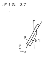
FIG. 27 illustrates variable ϕ1; -
FIG. 28 illustrates "pulling"; -
FIG. 29 illustrates "translation paddling"; -
FIG. 30 illustrates Z-axis component Vz of velocity vector V; -
FIG. 31 illustrates variable ϕ3; -
FIG. 32 illustrates an overview of processing in step S24 ofFIG. 26 ; -
FIG. 33 illustrates processing in step S25 ofFIG. 26 ; -
FIG. 34 illustrates the processing in step S25 ofFIG. 26 ; -
FIG. 35 illustrates processing in step S26 ofFIG. 26 ; and -
FIG. 36 illustrates processing in step S27 ofFIG. 26 . - Hereinafter, embodiments of the present invention will be described with reference to the drawings. The present invention is not limited to the embodiments.
- With reference to
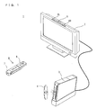
FIG. 1 , agame system 1 including a game apparatus, which is an example of a posture calculation device according to one embodiment of the present invention, will be described.FIG. 1 is an external view of thegame system 1. Hereinafter, a game apparatus and a game program according to this embodiment will be described. In the following example, the game apparatus is of an installation type. As shown inFIG. 1 , thegame system 1 includes a television receiver 2 (hereinafter, referred to simply as a "TV") 2, agame apparatus 3, anoptical disc 4, aninput device 8, and amarker section 6. In thegame system 1, game processing is executed by thegame apparatus 3 based on a game operation performed using theinput device 8. - In the
game apparatus 3, theoptical disc 4, which is an example of an information storage medium exchangeably usable for thegame apparatus 3, is detachably inserted. Theoptical disc 4 has stored thereon a game program to be executed by thegame apparatus 3. Thegame apparatus 3 has an insertion opening for inserting theoptical disc 4 on a front surface thereof. Thegame apparatus 3 reads and executes the game program stored on theoptical disc 4 inserted into the insertion opening, and thus performs the game processing. - The
game apparatus 3 is connected to theTV 2, which is an example of a display device, via a connection cord. TheTV 2 displays a game image obtained as a result of the game processing executed by thegame apparatus 3. Amarker section 6 is provided in the vicinity of a display screen of the TV 2 (above the display screen inFIG. 1 ). Themarker section 6 includes twomarkers marker 6R (also themarker 6L) includes one or more infrared LEDs, and outputs infrared light forward from theTV 2. Themarker section 6 is connected to thegame apparatus 3, and thegame apparatus 3 can control each of the infrared LEDs of themarker section 6 to be lit up or out. - The
input device 8 provides thegame apparatus 3 with operation data representing the particulars of the operation made thereon. In this embodiment, theinput device 8 includes acontroller 5 and agyrosensor unit 7. As described later in detail, in theinput device 8, thegyrosensor unit 7 is detachably connected to thecontroller 5. Thecontroller 5 and thegame apparatus 3 are connected with each other via wireless communication. In this embodiment, thecontroller 5 and thegame apparatus 3 are wirelessly communicable to each other by, for example, the Bluetooth (registered trademark) technology. In other embodiments, thecontroller 5 and thegame apparatus 3 may be connected with each other in a wired manner. - Next, with reference to
FIG. 2 , an internal structure of thegame apparatus 3 will be described.FIG. 2 is a block diagram showing a structure of thegame apparatus 3. Thegame apparatus 3 includes aCPU 10, asystem LSI 11, an externalmain memory 12, a ROM/RTC 13, adisc drive 14, an AV-IC 15, and the like. - The
CPU 10 performs the game processing by executing a game program stored on theoptical disc 4, and acts as a game processor. TheCPU 10 is connected to thesystem LSI 11. Thesystem LSI 11 is connected to theCPU 10 and also to the externalmain memory 12, the ROM/RTC 13, thedisc drive 14 and the AV-IC 15. Thesystem LSI 11 performs the processing of, for example, controlling data transfer between the elements connected thereto, generating images to be displayed, and obtaining data from external devices. An internal structure of thesystem LSI 11 will be described later. The externalmain memory 12, which is of a volatile type, has stored thereon a program such as a game program read from theoptical disc 4, a game program read from aflash memory 17 or the like, or various other data. The externalmain memory 12 is used as a work area or a buffer area of theCPU 10. The ROM/RTC 13 includes a ROM having a program for starting thegame apparatus 3 incorporated thereon (so-called boot ROM) and a clock circuit for counting time (RTC: Real Time Clock). Thedisc drive 14 reads program data, texture data or the like from theoptical disc 4 and writes the read data onto an internalmain memory 11e described later or the externalmain memory 12. - The
system LSI 11 includes an input/output processor (I/O processor) 11a, a GPU (Graphics Processor Unit) 11b, a DSP (Digital Signal Processor) 11c, aVRAM 11d, and the internalmain memory 11e. Although not shown, theseelements 11a through 11e are connected with each other via an internal bus. - The
GPU 11b is a part of drawing means and generates an image in accordance with a graphics command (a command to draw an image) from theCPU 10. TheVRAM 11d has stored thereon data necessary for theGPU 11b to execute the graphics command (polygon data, texture data or other data). TheGPU 11b uses the data stored on theVRAM 11d to generate an image. - The
DSP 11c acts as au audio processor and generates audio data using sound data or sound wave (sound tone) data stored on the internalmain memory 11e or the externalmain memory 12. - The image data and the audio data generated as described above are read by the AV-
IC 15. The AV-IC 15 outputs the read image data to theTV 2 via anAV connector 16, and outputs the read audio data to aspeaker 2a built in theTV 2. Thus, the image is displayed on theTV 2 and also the sound is output from thespeaker 2a. - The input/
output processor 11a transmits or receives data to or from the elements connected thereto, or downloads data from external devices. The input/output processor 11a is connected to theflash memory 17, awireless communication module 18, awireless controller module 19, anexpansion connector 20, and amemory card connector 21. Thewireless communication module 18 is connected to anantenna 22, and thewireless controller module 19 is connected to anantenna 23. - The input/
output processor 11a is connected to a network via thewireless communication module 18 and theantenna 22, and thus can communicate with other game apparatuses or various servers also connected to the network. The input/output processor 11a periodically accesses theflash memory 17, and detects whether or not there is data which needs to be transmitted to the network. When there is such data, the input/output processor 11a transmits such data to the network via thewireless communication module 18 and theantenna 22. The input/output processor 11a also receives data transmitted from other game apparatuses or data downloaded from a download server via the network, theantenna 22 and thewireless communication module 18, and stores the received data on theflash memory 17. TheCPU 10 executes the game program and thus reads the data stored on theflash memory 17 to be used for the game program. Theflash memory 17 may have stored therein data saved as a result of playing the game using the game apparatus 3 (data representing a result or a state in the middle of the game) as well as the data to be transmitted to, or data received from, the other game apparatuses or various servers. - The input/
output processor 11a receives operation data which is transmitted from thecontroller 5 via theantenna 23 and thewireless controller module 19 and stores (temporarily stores) the operation data in a buffer area of the internalmain memory 11e or the externalmain memory 12. - The input/
output processor 11a is connected to theexpansion connector 20 and thememory card connector 21. Theexpansion connector 20 is a connector for an interface such as USB, SCSI or the like. Theexpansion connector 20 may be connected to a medium such as an external storage medium or the like, may be connected to a peripheral device such as another controller or the like, or may be connected to a wired communication connector, to communicate with the network instead of thewireless communication module 18. Thememory card connector 21 is a connector for an external storage medium such as a memory card or the like. For example, the input/output processor 11a can access an external storage medium via theexpansion connector 20 or thememory card connector 21 to store data on the external storage medium or read data from the external storage medium. - The
game apparatus 3 has apower button 24, areset button 25, and aneject button 26. Thepower button 24 and thereset button 25 are connected to thesystem LSI 11. When thepower button 24 is turned on, the elements of thegame apparatus 3 are provided with power via an AC adaptor (not shown). When thereset button 25 is pressed, thesystem LSI 11 restarts a starting program of thegame apparatus 3. Theeject button 26 is connected to thedisc drive 14. When theeject button 26 is pressed, theoptical disc 4 is dismounted from thedisc drive 14. - With reference to
FIG. 3 through FIG. 6 , theinput device 8 will be described.FIG. 3 is an isometric view showing an external structure of theinput device 8.FIG. 4 is an isometric view showing an external structure of thecontroller 5.FIG. 3 is an isometric view of theinput device 8 seen from the top rear side thereof.FIG. 4 is an isometric view of thecontroller 5 seen from the bottom front side thereof. - As shown in
FIG. 3 andFIG. 4 , thecontroller 5 includes ahousing 31 formed by, for example, plastic molding. Thehousing 31 has a generally parallelepiped shape extending in a longitudinal or front-rear direction (Z-axis direction shown inFIG. 3 ). The overall size of thehousing 31 is small enough to be held by one hand of an adult or even a child. A player can perform a game operation by, for example, pressing buttons provided in thecontroller 5 or moving thecontroller 5 itself to change the position or posture thereof. - The
housing 31 has a plurality of operation buttons. As shown inFIG. 3 , provided on a top surface of thehousing 31 are across button 32a, afirst button 32b, asecond button 32c, anA button 32d, aminus button 32e, ahome button 32f, aplus button 32g, and apower button 32h. In this specification, the top surface on which thesebuttons 32a through 32h are provided will be occasionally referred to as the "button surface". As shown inFIG. 4 , a recessed portion is formed on a bottom surface of thehousing 31, and aB button 32i is provided on a slope surface of the recessed portion. Theoperation buttons 32a through 32i are assigned various functions in accordance with the game program executed by thegame apparatus 3. Thepower button 32h is for remote-controlling the power of the main body of thegame apparatus 3 to be on or off. Thehome button 32f and thepower button 32h have a top surface thereof buried in the top surface of thehousing 31, so as not to be inadvertently pressed by the player. - On a rear surface of the
housing 31, aconnector 33 is provided. Theconnector 33 is used for connecting thecontroller 5 with another device (for example, thegyrosensor unit 7 or another controller). On both sides of theconnector 33 on the rear surface of thehousing 31,engagement holes 33a are provided for preventing such another device from easily coming off. - In a rear part of the top surface of the
housing 31, a plurality of LEDs (inFIG. 3 , four LEDs) 34a through 34d are provided. Thecontroller 5 is assigned a controller type (number) so as to be distinguishable from other main controllers. TheLEDs 34a through 34d are used for, for example, informing the player of the controller type which is currently set to thecontroller 5 that he/she is using, or for informing the player of the remaining battery amount. Specifically, when thecontroller 5 is used for the game operation, one of the plurality ofLEDs 34a through 34d corresponding to the controller type is lit up. - The
controller 5 includes an imaging information calculation section 35 (FIG. 6 ). As shown inFIG. 4 , alight incident face 35a of the imaginginformation calculation section 35 is provided on a front surface of thehousing 31. Thelight incident face 35a is formed of a material which allows infrared light from themarkers - On the top surface of the
housing 31,sound holes 31a are formed between thefirst button 32b and thehome button 32f for releasing the sound outside from a speaker 49 (FIG. 5 ) built in thecontroller 5. - Now, with reference to
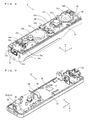
FIG. 5 and FIG. 6 , an internal structure of thecontroller 5 will be described.FIG. 5 and FIG. 6 illustrate an internal structure of thecontroller 5.FIG. 5 is an isometric view illustrating a state where an upper casing (a part of the housing 31) of thecontroller 5 is removed.FIG. 6 is an isometric view illustrating a state where a lower casing (a part of the housing 31) of thecontroller 5 is removed.FIG. 6 shows a reverse side of asubstrate 30 shown inFIG. 5 . - As shown in
FIG. 5 , thesubstrate 30 is fixed inside thehousing 31. On a top main surface of thesubstrate 30, theoperation buttons 32a through 32h, theLEDs 34a through 34d, anacceleration sensor 37, anantenna 45, thespeaker 49 and the like are provided. These elements are connected to a microcomputer 42 (seeFIG. 6 ) via lines (not shown) formed on thesubstrate 30 and the like. In this embodiment, theacceleration sensor 37 is provided off the center line of thecontroller 5 along an X-axis direction. This makes it easier to calculate the motion of thecontroller 5 when thecontroller 5 is rotated around the Z axis. Theacceleration sensor 37 is also located forward with respect to the center of thecontroller 5 along the longitudinal direction thereof (Z-axis direction). The provision of a wireless module 44 (FIG. 7 ) and theantenna 45 allows thecontroller 5 to act as a wireless controller. - As shown in
FIG. 6 , at a front edge of a bottom main surface of thesubstrate 30, the imaginginformation calculation section 35 is provided. The imaginginformation calculation section 35 includes aninfrared filter 38, alens 39, animaging element 40 and animage processing circuit 41 located in this order from the front surface of thecontroller 5. Theseelements 38 through 41 are attached to the bottom main surface of thesubstrate 30. - On the bottom main surface of the
substrate 30, themicrocomputer 42 and avibrator 48 are provided. Thevibrator 48 may be, for example, a vibration motor or a solenoid, and is connected to themicrocomputer 42 via lines provided on thesubstrate 30 and the like. Thecontroller 5 is vibrated by an actuation of thevibrator 48 based on an instruction from themicrocomputer 42, and the vibration is conveyed to the hand of the player holding thecontroller 5. Thus, a so-called vibration-responsive game is realized. In this embodiment, thevibrator 48 is located slightly forward with respect to the center of thehousing 31. Since thevibrator 48 is provided closer to a front end than the center of thecontroller 5, the vibration of thevibrator 48 can vibrate theentire controller 5 more significantly. Theconnector 33 is attached at a rear edge of the main bottom surface of thesubstrate 30. In addition to the elements shown inFIG. 5 and FIG. 6 , thecontroller 5 includes a quartz oscillator for generating a reference clock of themicrocomputer 42, an amplifier for outputting an audio signal to thespeaker 49, and the like. - The
gyrosensor unit 7 includes gyrosensors (gyrosensors FIG. 7 ) for sensing an angular velocity around the three axes. Thegyrosensor unit 7 is detachably attached on theconnector 33 of thecontroller 5. At a front end of the gyrosensor unit 7 (an end thereof in a positive Z-axis direction shown inFIG. 3 ), a plug (aplug 53 shown inFIG. 7 ) connectable to theconnector 33 is provided. On both sides of theplug 53, hooks (not shown) are provided. In the state where thegyrosensor unit 7 is attached to thecontroller 5, theplug 53 is connected to theconnector 33 and the hooks are engaged with theengagement holes 33a of thecontroller 5. Thus, thecontroller 5 and thegyrosensor unit 7 are firmly secured to each other. Thegyrosensor unit 7 also includesbuttons 51 on side surfaces thereof (side surfaces perpendicular to the X-axis direction shown inFIG 3 ). Thebuttons 51 are structured so as to release the hooks from theengagement holes 33a when being pressed. By pulling theplug 53 from theconnector 33 while pressing thebuttons 51, thegyrosensor unit 7 can be detached from thecontroller 5. - At a rear end of the
gyrosensor unit 7, a connector having the same shape as that of theconnector 33 is provided. Therefore, other devices attachable to the controller 5 (theconnector 33 of the controller 5) can be attached to the connector of thegyrosensor unit 7. InFIG. 3 , acover 52 is detachably attached to the connector of thegyrosensor unit 7. - The shape of the
controller 5 and thegyrosensor unit 7, the shape, number and position of the operation buttons, the acceleration sensor and the vibrator, and the like shown inFIG. 3 through FIG. 6 are merely exemplary, and may be altered without departing from the scope of the present invention. In this embodiment, the imaging direction of the imaging means is the positive Z-axis direction, but the imaging direction may be any direction. Specifically, the position of the imaging information calculation section 35 (thelight incident face 35a of the imaging information calculation section 35) in thecontroller 5 does not need to be on the front surface of thehousing 31, and may be on another surface as long as light can enter from the outside of thehousing 31. -
FIG. 7 is a block diagram showing a structure of the input device 8 (thecontroller 5 and the gyrosensor unit 7). Thecontroller 5 includes the operation section 32 (operation buttons 32a through 32i), theconnector 33, the imaginginformation calculation section 35, acommunication section 36, and theacceleration sensor 37. Thecontroller 5 transmits operation data representing the particulars of the operation made thereon to thegame apparatus 3 as operation data. - The
operation section 32 includes the above-describedoperation buttons 32a through 32i, and outputs operation button data representing an input state of each of theoperation buttons 32a through 32i (whether each of theoperation buttons 32a through 32i has been pressed or not) to themicrocomputer 42 of thecommunication section 36. - The imaging
information calculation section 35 is a system for analyzing image data taken by the imaging means, distinguishing an area having a high brightness in the image data, and calculating the center of gravity, the size and the like of the area. The imaginginformation calculation section 35 has, for example, a maximum sampling cycle of about 200 frames/sec., and therefore can trace and analyze even a relatively fast motion of thecontroller 5. - The imaging
information calculation section 35 includes theinfrared filter 38, thelens 39, theimaging element 40 and theimage processing circuit 41. Theinfrared filter 38 allows only infrared light to pass therethrough, among light incident on the front surface of thecontroller 5. Thelens 39 collects the infrared light which has been transmitted through theinfrared filter 38 and causes the infrared light to be incident on theimaging element 40. Theimaging element 40 is a solid-state imaging device such as, for example, a CMOS sensor or a CCD sensor. Theimaging element 40 receives the infrared light collected by thelens 39 and outputs an image signal. Themarkers marker section 6 located in the vicinity of the screen of theTV 2 each include an infrared LED for outputting infrared light forward from the TV2. The provision of theinfrared filter 38 allows theimaging element 40 to receive only the infrared light transmitted through theinfrared filter 38 to generate image data. Therefore, the image of each of themarkers imaging element 40 will be referred to as a "taken image". The image data generated by theimaging element 40 is processed by theimage processing circuit 41. Theimage processing circuit 41 calculates the positions of imaging targets (themarkers image processing circuit 41 outputs a coordinate representing the calculated position to themicrocomputer 42 of thecommunication section 36. The data on the coordinate is transmitted by themicrocomputer 42 to thegame apparatus 3 as operation data. Hereinafter, this coordinate will be referred to as a "marker coordinate". The marker coordinate changes in accordance with the direction (inclining angle) or the position of thecontroller 5 itself, and therefore thegame apparatus 3 can calculate the direction or the position of thecontroller 5 using the marker coordinate. - In other embodiments, the
controller 5 does not need to include theimage processing circuit 41, and a taken image itself may be transmitted from thecontroller 5 to thegame apparatus 3. In this case, thegame apparatus 3 may include a circuit or program having substantially the same function as that of theimage processing circuit 41 and calculate the marker coordinate. - The
acceleration sensor 37 detects an acceleration (including a gravitational acceleration) of thecontroller 5. Namely, theacceleration sensor 37 detects a force (including the force of gravity) applied to thecontroller 5. Theacceleration sensor 37 detects a value of the acceleration in a linear direction along a sensing axis (linear acceleration) among accelerations acting on a detection section of theacceleration sensor 37. For example, in the case of a multi-axial (at least two-axial) acceleration sensor, an acceleration component along each axis is detected as an acceleration acting on the detection section of the acceleration sensor. For example, a three-axial or two-axial acceleration sensor may be of a type available from Analog Devices, Inc. or STMicroelectronics N.V. Theacceleration sensor 37 is, for example, of an electrostatic capacitance type, but may be of any other system. - In this embodiment, the
acceleration sensor 37 detects a linear acceleration in each of an up-down direction with respect to the controller 5 (Y-axis direction shown inFIG. 3 ), a left-right direction with respect to the controller 5 (X-axis direction shown inFIG. 3 ), and a front-rear direction with respect to the controller 5 (Z-axis direction shown inFIG. 3 ). Since theacceleration sensor 37 detects an acceleration in the linear direction along each axis, the output from theacceleration sensor 37 represents a value of the linear acceleration along each of the three axes. Namely, the detected acceleration is represented as a three-dimensional vector (ax, ay, az) in an XYZ coordinate system (controller coordinate system) which is set with respect to the input device (controller 5). Hereinafter, a vector having, as components, acceleration values along the three axes detected by theacceleration sensor 37 will be referred to as the "acceleration vector". - Data representing the acceleration detected by the acceleration sensor 37 (acceleration data) is output to the
communication section 36. Since the acceleration detected by theacceleration sensor 37 changes in accordance with the direction (inclining angle) or the motion of thecontroller 5 itself, thegame apparatus 3 can calculate the direction or the motion of thecontroller 5 using the acceleration data. In this embodiment, thegame apparatus 3 calculates the posture of thecontroller 5 based on the acceleration data. - Data (acceleration data) representing the acceleration detected by the acceleration sensor 37 (acceleration vector) is output to the
communication section 36. In this embodiment, theacceleration sensor 37 is used as a sensor for outputting data for determining the inclining angle of thecontroller 5. - A computer such as a processor of the game apparatus 3 (for example, the CPU 10) or a processor of the controller 7 (for example, the microcomputer 42) executes processing based on an acceleration signal which is output from the
acceleration sensor 37, and as a result, can estimate or calculate (determine) further information on thecontroller 5. A person of ordinary skill in the art would easily understand this from the description of this specification. For example, when the computer executes processing with a premise that thecontroller 5 including theacceleration sensor 37 is in a static state (i.e., when the computer executes processing with a premise that the acceleration detected by theacceleration sensor 37 includes only a gravitational acceleration), if thecontroller 5 is actually in a static state, it can be found based on the detected acceleration whether or not the posture of thecontroller 5 is inclined with respect to the direction of gravity, or how much the posture of thecontroller 5 is inclined with respect to the direction of gravity. Specifically, where the state in which a detection axis of theacceleration sensor 37 is directed vertically downward is a reference state, it can be found whether or not thecontroller 5 is inclined with respect to the reference state based on whether or not 1 G (gravitational acceleration) is applied to thecontroller 5. Based on the magnitude of the gravitational acceleration, it can also be found how much thecontroller 5 is inclined with respect to the reference state. In the case of amulti-axial acceleration sensor 37, it can be found more precisely how much thecontroller 5 is inclined with respect to the direction of gravity by processing a signal representing an acceleration along each axis. In this case, the processor may calculate the inclining angle of thecontroller 5 based on an output from theacceleration sensor 37, or may calculate the inclining angle of thecontroller 5 without calculating the inclining angle. By using theacceleration sensor 37 in combination with a processor in this manner, the inclining angle or posture of thecontroller 5 can be determined. - By contrast, with a premise that the
controller 5 is in a dynamic state (in the state where thecontroller 5 is being moved), theacceleration sensor 37 detects an acceleration in accordance with the motion of thecontroller 5 in addition to the gravitational acceleration. Therefore, the moving direction of thecontroller 5 can be found by removing a component of the gravitational acceleration from the detected acceleration using predetermined processing. Even with the premise that thecontroller 5 is in a dynamic state, the inclination of thecontroller 5 with respect to the direction of gravity can be found by removing a component of the acceleration in accordance with the motion of the acceleration sensor from the detected acceleration using predetermined processing. In other embodiments,theacceleration sensor 37 may include an incorporated processing device or other types of dedicated device for executing predetermined processing on an acceleration signal detected by built-in acceleration detection means before the detected acceleration signal is output to themicrocomputer 42. In the case where theacceleration sensor 37 is used for, for example, detecting a static acceleration (for example, a gravitational acceleration), the incorporated or dedicated processing device may be of a type for converting the acceleration signal into an inclining angle (or any other preferable parameter). - The
communication section 36 includes themicrocomputer 42, amemory 43, thewireless module 44 and theantenna 45. Themicrocomputer 42 controls thewireless module 44 for wirelessly transmitting the data obtained by themicrocomputer 42 to thegame apparatus 3 while using thememory 43 as a storage area during processing. Themicrocomputer 42 is connected to theconnector 33. Data transmitted from thegyrosensor unit 7 is input to themicrocomputer 42 via theconnector 33. Hereinafter, thegyrosensor unit 7 will be described. - The
gyrosensor unit 7 includes theplug 53, amicrocomputer 54, the two-axial gyrosensor 55 and the mono-axial gyrosensor 56. As described above, thegyrosensor unit 7 detects an angular velocity around three axes (in this embodiment, the X, Y and Z axes) and transmits data representing each detected angular velocity (angular velocity data) to thecontroller 5. - The two-
axial gyrosensor 55 detects an angular velocity (per unit time) around the X axis and an angular velocity around the Y axis (per unit time). The mono-axial gyrosensor 56 detects an angular velocity around the Z axis (per unit time). In this specification, with respect to the imaging direction of the controller 5 (the positive Z-axis direction), the rotation directions around the X, Y and Z axes will be referred to as the "pitch direction", the "yaw direction" and "roll direction", respectively. Namely, the two-axial gyrosensor 55 detects the angular velocity in the pitch direction (rotation direction around the X axis) and the yaw direction (rotation direction around the Y axis), and the mono-axial gyrosensor 56 detects the angular velocity in the roll direction (rotation direction around the Z axis) (seeFIG. 8 ). - In this embodiment, the two-
axial gyrosensor 55 and the mono-axial gyrosensor 56 are used in order to detect the angular velocity around the three axes. In other embodiments, the number and combination of the gyrosensors to be used are not specifically limited as long as the angular velocity around the three axes can be detected. - In this embodiment, for the purpose of facilitating calculations in posture calculation processing described later, the three axes around which the
gyrosensors acceleration sensor 37 detects the acceleration (X, Y and Z axes) . In other embodiments, the three axes around which thegyrosensors acceleration sensor 37 detects the acceleration. - Data representing the angular velocity detected by each of the
gyrosensors microcomputer 54. Accordingly, data representing the angular velocity around the three axes, i.e., the X, Y and Z axes is input to themicrocomputer 54. Themicrocomputer 54 transmits the data representing the angular velocity around the three axes as the angular velocity data to thecontroller 5 via theplug 53. The transmission from themicrocomputer 54 to thecontroller 5 is performed at a predetermined cycle. Since game processing is generally performed at a cycle of 1/60 sec. (at a cycle of frame time), the transmission is preferably performed at a cycle of a time period equal to or shorter than 1/60 sec. - Now, the description of the
controller 5 will be resumed. Data which is output from theoperation section 32, the imaginginformation calculation section 35, and theacceleration sensor 37 to themicrocomputer 42, and data transmitted from thegyrosensor unit 7 to themicrocomputer 42, are temporarily stored on thememory 43. Such data is transmitted to thegame apparatus 3 as the operation data. Namely, at the transmission timing to thewireless controller module 19 of thegame apparatus 3, themicrocomputer 42 outputs the operation data stored on thememory 43 to thewireless module 44. Thewireless module 44 modulates a carrier wave of a predetermined frequency with the operation data and radiates the resultant very weak radio signal from theantenna 45, using, for example, the Bluetooth (registered trademark) technology. Namely, the operation data is modulated into a very weak radio signal by thewireless module 44 and transmitted from thecontroller 5. The very weak radio signal is received by thewireless controller module 19 on the side of thegame apparatus 3. The received very weak radio signal is demodulated or decoded, and thus thegame apparatus 3 can obtain the operation data. TheCPU 10 of thegame apparatus 3 executes the game processing based on the obtained operation data and the game program. The wireless communication from thecommunication section 36 to thewireless controller module 19 is performed at a predetermined cycle. Since game processing is generally performed at a cycle of 1/60 sec. (at a cycle of frame time), the wireless transmission is preferably performed at a cycle of a time period equal to or shorter than 1/60 sec. Thecommunication section 36 of thecontroller 5 outputs each piece of the operation data to thewireless controller module 19 of thegame apparatus 3 at rate of, for example, once in 1/200 seconds. - By using the
controller 5, the player can perform an operation of inclining thecontroller 5 at an arbitrary inclining angle, in addition to a conventional general game operation of pressing the operation buttons. With thecontroller 5 described above, the player can also perform an operation of indicating an arbitrary position on the screen by thecontroller 5 and also an operation of moving thecontroller 5 itself. - Now, with reference to
FIG. 9 through FIG. 12 , an overview of a game assumed in this embodiment will be described. The game assumed in this embodiment uses canoe as a material.FIG. 9 shows an exemplary game screen assumed in this embodiment. InFIG. 9 , the game screen displays aplayer object 101 on a canoe (for one person) and apaddle 102 for paddling a canoe (single blade paddle). In this game, the player uses theinput device 8 as if theinput device 8 was a paddle of the canoe (more accurately, a grasp of the paddle) and moves theinput device 8 as if paddling the canoe (paddling through the water). Thus, as shown inFIG. 9 through FIG. 12 , thepaddle 102 in the game screen is also moved. The player can paddle through the water in a virtual game space to move the canoe in this manner, and thus can enj oy pseudo canoeing. - An operation method of this game will be described in more detail. In this game, the player holds the
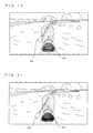
input device 8 as if theinput device 8 was a paddle as described above. The player plays the game by performing an operation mimicking paddling (hereinafter, referred to simply as "paddling operation"). In this embodiment, the paddling operation is detected and reflected on the posture or motion of thepaddle 102 in the virtual game space.FIG. 13 andFIG. 14 schematically show an example of the paddling operation performed by the player. As shown inFIG. 13 , the player holds theinput device 8 with his/her right hand such that the button surface of theinput device 8 is directed toward the player. InFIG. 13 , the player holds theinput device 8 with only his/her right hand for the convenience of description, but the player may operate theinput device 8 with both of his/her hands. - As shown in
FIG. 14 , the player holding theinput device 8 as described above moves theinput device 8 to a position behind him/her as if paddling through the water (FIG. 14(a) through FIG. (c)). Then, the player once moves theinput device 8 upward as if pulling the paddle up from the water, and then moves theinput device 8 forward (FIG. 14(d) through FIG. 14(f) ). Basically, the player repeats such an operation to perform a paddling operation. - In this game, as shown in
FIG. 15 through FIG. 19 , the player may optionally switch the paddling position from right to left or vice versa in accordance with the progress of the game. InFIG. 15 through FIG. 19 , the paddling position is switched from left to right. In this case, the player, who has been performing the paddling operation on the left side of his/her body, moves theinput device 8 to the right side of his/her body (in the case where the player performs the operation with a single hand, the player switches the hand holding theinput device 8 from left to right) and continues the paddling operation. - The motion of the
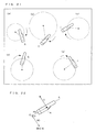
input device 8 in the above-described paddling operation draws a locus as shown inFIG. 20 . A motion made by a human being is considered to be formed of a combination of rotations around joints. Considering this series of motions by a predetermined unit time (represented with letters A through G inFIG. 20 ), the motion of theinput device 8 of each unit time can be regarded as a part of a rotation motion made around a certain position as the center.FIG. 21 shows the states of theinput device 8 at the unit times A, C, E, G and H inFIG. 20 . As shown inFIG. 21 , the motion of each unit time is a part of a rotation motion made around a certain position as the center. For example, in the case where a motion is made only by a rotation of the elbow, the center is the position of the elbow. In the case where a motion is made by a rotation of both of the elbow and the shoulder, a motion provided by the influence of the rotations of the elbow and the shoulder can be regarded as a rotation motion made around a certain position other than the elbow or the shoulder as the center. In other words, the velocity generated in theinput device 8 is provided by a rotation motion made around a certain position as the center. Since it is difficult for a human being to make a perfectly circular motion, the center position or radius of the circular motion is slightly changed timing by timing. - In this embodiment, the following processing is executed. The posture of the
input device 8 is estimated based on the acceleration and the angular velocity obtained from theacceleration sensor 37 and thegyrosensor unit 7, and the center position of the rotation motion and the moving velocity of theinput device 8 are also estimated. Then, these estimated elements are reflected on the posture and motion of thepaddle 102. - Now, the principle for estimating the center of the rotation motion or the moving velocity in this embodiment will be described. Here, a state shown in
FIG. 22 will be used as an example.FIG. 22 shows the relationship between theinput device 8 and the rotation motion in a certain unit time. It is assumed that theinput device 8 rotates around the X axis in the controller coordinate system (local coordinate system) of theinput device 8. Hereinafter, the vector of this rotational axis direction (the X-axis direction in this case) will be represented with ω (hereinafter, this vector will occasionally be referred to as "rotation axis vector ω"). The rotation velocity is represented with the magnitude of vector ω. InFIG. 22 , the position of the input device 8 (in this embodiment, the position of the center part of the input device 8) is represented with R, the center of the rotation motion is represented with C, and the vector from C to R regarding the rotation motion is represented as vector Rs (hereinafter, this vector will occasionally be referred to as "radial vector Rs"). Vector Rs indicates the relative positional relationship between the rotation center C and theinput device 8, and also indicates the radius of the rotationmotion. The vector indicating the moving velocity of theinput device 8 in the rotation motion is represented with V (hereinafter, this vector will occasionally be referred to as "velocity vector V"). A predetermined position in the controller coordinate system of theinput device 8 is set as the origin. The vector from the origin to the rotation center is represented as vector R0. - In the exemplary state shown in
FIG. 22 , velocity vector V can be found by the outer product of vector ω and vector Rs as represented by the following expression.
- In
expression 1, "x" represents the outer product (this is also applied to the following expressions). - Vector ω can be calculated based on the output from the
gyrosensor unit 7. Specifically, a vector having, as x, y and z components, angular velocities around the three axes of the X, Y and Z axes output from thegyrosensor unit 7 is rotation axis vector ω. Vector Rs can be calculated as follows. - Regarding the series of motions performed on the
input device 8 as shown inFIG. 14 , the center position of the rotation motion may be slightly changed (varying amount R0 inFIG. 22 may be slightly changed) occasionally. Nonetheless, in the case of the paddling operation as shown inFIG. 14 , such a center position is considered to change relatively very slowly as compared with the rotation motion itself. Accordingly, in this embodiment, the influence of the change of the center position of the paddling operation is considered to be negligible with respect to the rotation motion itself. Namely, regarding the series of motions in the paddling operation as shown inFIG. 14 , the translational motion is ignored and only the rotation motion is considered to be performed. For this reason, the right term ofexpression 1 is provided by an approximation made to exclude a component by the movement of the center position, i.e., by a change of R0. The following expression is derived by differentiatingexpression 1.

- In
expression 2, "A" is a differential of V and indicates an acceleration. "A" can be specif iedby an acceleration component (hereinafter, referred to as the "motion component") obtained by removing a gravity component from the acceleration obtained from the acceleration sensor. The elements represented by letters having a dot thereabove each represent a differential. "[I]" represents a unit matrix. - The following expression is derived by transforming
expression 2.
- The following expression is derived by transforming
expression 3.
- Vector ω is a rotation axis and vector Rs is a radius of rotation. Therefore, defining vector Rs as having the shortest possible length (i.e., the rotation center and the
input device 8 has the same depth inFIG. 22 ), vector ω and vector Rs always cross each other perpendicularly. These vectors crossing each other perpendicularly means that the inner product is 0. Accordingly, inexpression 4 above, the element of "(ω·Rs)ω" is "0". As a result, the following expression is obtained by transformingexpression 4.
- As shown in
expression 5, vector Rs can be calculated once motion component A and vector ω are found. Motion component A is found by removing the gravity component from the acceleration component. In order to remove the gravity component, the direction of gravity needs to be found. In this embodiment, the posture of theinput device 8 is estimated based on the angular velocity and the acceleration, and the direction of gravity is estimated based on the estimated posture. - In consideration of the above,
expression 2 is transformed. As a result, the following expression is obtained.
- As shown in
expression 6, vector Rs can be calculated once motion component A, angular velocity ω and the angular acceleration are found. In this embodiment, the posture of theinput device 8 is estimated based on the angular velocity and the acceleration, and motion component A is estimated based on the estimated posture. Once motion component A is calculated, vector Rs can be calculated as described above. Once vector Rs is calculated, the processing of calculating velocity V by obtaining the outer product of vector Rs and vectorω using expression 1 is executed. - Now, an overview of the processing executed in this embodiment will be described.
FIG. 23 shows an overview of the processing executed in this embodiment. InFIG. 23 , the elements surrounded by square represent generating sources of data. The elements surrounded by circle represent processes and are provided with reference numerals in the "pn" form (n is an integer). The elements sandwiched by upper and lower lines represent data (and the areas in which the data is stored; corresponding to the memory map ofFIG. 24 ), and are provided with reference numerals in the "dn" form (n is an integer). - With reference to
FIG. 23 , angular velocity d1 is obtained from thegyrosensor unit 7. Acceleration d2 is obtained from theacceleration sensor 37. Angular velocity d1 and acceleration d2 are input to the process of posture estimation p1. In posture estimation p1, the processing of estimating the posture of theinput device 8 based on angular velocity d1 and acceleration d2 and outputting the estimated posture of theinput device 8 as estimated posture d3 is executed. For calculating the estimated posture based on the acceleration and the angular velocity, any method is usable. In this embodiment, a posture vector represented by the angular velocity is corrected by a vector represented by the acceleration to calculate the posture of theinput device 8. Ideally, by updating the posture based on the angular velocity at every unit time, the posture of theinput device 8 can be calculated only based on the angular velocity, and the downward direction in an actual space viewed from the input device 8 (i.e., the direction of gravity) is estimated from the relationship between the space and the posture. However, there is a possibility that the output from thegyrosensor unit 7 includes an error. In the case where an error is included, the posture calculated as described above has errors accumulated therein as time passes. By contrast, the output from the acceleration sensor is an acceleration applied on theinput device 8. Such an output includes only a gravity component when theinput device 8 is static, but includes accelerations other than the gravity component when theinput device 8 is moving. For this reason, it is difficult to estimate the direction of gravity only based on the acceleration. Therefore, the estimated posture is updated based on the angular velocity, and further the posture is corrected such that the direction of gravity estimated based on the posture becomes closer to the direction represented by the acceleration. At this time, as the magnitude of the acceleration is closer to the magnitude of the gravitational acceleration, the degree of correction is made larger. By performing such a correction, the posture is calculated more accurately based on the acceleration when there is little motion of theinput device 8, and the posture can be always estimated with a certain degree of appropriateness even when theinput device 8 is moving. - Estimated posture d3 calculated in posture estimation p1 is input to the process of gravity component removal p3. In gravity component removal p3, the processing of calculating a gravity component based on estimated posture d3 is executed. The direction of gravity is estimated in correspondence with the posture, and the magnitude of gravity is 1 G as already known. In gravity component removal p3, acceleration d2 is further obtained and a gravity component is removed from acceleration d2. Thus, a motion component d4 deprived of the influence of the gravity is calculated. Motion component d4 is input to the process of rotation center estimation p4 described later.
- Angular velocity d1 is also input to each of the processes of time series difference p2, rotation center estimation p4 and velocity calculation p5. In time series difference p2, the processing of calculating angular acceleration d5 based on angular velocity d1 is executed. Angular acceleration d5 calculated is input to rotation center estimation p4.
- In rotation center estimation p4, the processing of estimating center C of the above-described rotation motion based on angular velocity d1, motion component d4 and angular acceleration d5 by applying the above-described expressions is executed. More specifically, the processing of calculating vector Rs described above is executed. Data representing vector Rs calculated is output as radius vector d6.
- Radius vector d6 is input to the process of velocity calculation p5. In velocity calculation p5, the processing of estimating moving velocity V of the
input device 8 based on angular velocity d1 and radius vector d6 by the above-described expression is executed. As a result, estimated velocity d7 is output. - As described above, in this embodiment, the processing is executed of outputting the moving velocity of the
input device 8 in the rotation motion using, as inputs, the angular velocity and the acceleration which are output from thegyrosensor unit 7 and theacceleration sensor 37. In the game processing in this embodiment, varies data including the moving velocity described above is used for controlling the posture of thepaddle 102. - Now, the processing executed by the
game apparatus 3 willbedescribedinmoredetail. First, with reference toFIG. 24 , main data used in the processing executed by thegame apparatus 3 will be described.FIG. 24 shows main data stored in the main memory of the game apparatus (the externalmain memory 12 or the internalmain memory 11e). As shown inFIG. 24 , the main memory of thegame apparatus 3 has stored therein agame program 120,operation data 122 andgame processing data 127. In addition to the data shown inFIG. 24 , the main memory also has stored therein image data on various objects appearing in the game, data representing various parameters of the objects, and other data necessary for the game. - The
game program 120 is partially or entirely read from theoptical disc 4 and stored in the main memory at an appropriate timing after the power of thegame apparatus 3 is turned on. Thegame program 120 includes apaddling operation program 121. Thepaddling operation program 121 is a program for executing the processing of calculating the posture of theinput device 8 and controlling the posture of thepaddle 102 based on the posture of theinput device 8. - The
operation data 122 is transmitted from the controller 5 (input device 8) to thegame apparatus 3. As described above, the operation data is transmitted from thecontroller 5 to thegame apparatus 3 at a rate of once in 1/200 seconds. Therefore, theoperation data 122 stored in the externalmain memory 12 is updated at this rate. - The
operation data 122 includesangular velocity data 123,acceleration data 124, marker coordinatedata 125 andoperation button data 126. Theangular velocity data 123 represents the angular velocity detected by the gyrosensors 55 and 56 of the gyrosensor unit 7 (corresponding to angular velocity d1 inFIG. 23 ). In this embodiment, theangular velocity data 123 represents an angular velocity around each of the X, Y and Z axes shown inFIG. 3 . Theacceleration data 124 represents the acceleration detected by the acceleration sensor 37 (corresponding to acceleration d2 inFIG. 23 ). In this embodiment, theacceleration data 124 represents a three-dimensional acceleration vector having accelerations in the three axial directions of X, Y and Z as components. In this embodiment, the magnitude of the acceleration vector detected by theacceleration sensor 37 in the state where thecontroller 5 is static is set to "1". Namely, the magnitude of the gravitational acceleration detected by theacceleration sensor 37 is "1". - The marker coordinate
data 125 represents a coordinate calculated by theimage processing circuit 41 of the imaginginformation calculation section 35, i.e., the above-mentioned marker coordinate. The marker coordinate is represented in a two-dimensional coordinate system for indicating a position on a plane corresponding to the taken image. In the case where twomarkers imaging element 40, two marker coordinates are calculated. By contrast, in the case where only one of themarkers imaging element 40, only one marker is imaged by theimaging element 40 and only one marker coordinate is calculated. In the case where neithermarkers 6R nor 6L is present in the range which can be imaged by theimaging element 40, no marker is imaged by theimaging element 40 and no marker coordinate is calculated. Accordingly, the marker coordinatedata 125 may represent two marker coordinates or one marker coordinate, or may indicate that there is no marker coordinate. - The
operation button data 126 represents an input state of each of theoperation buttons 32a through 32i. - The
game processing data 127 is used in the game processing described later (shown in the flowcharts ofFIG. 25 andFIG. 26 ). Thegame processing data 127 includes estimatedposture data 128,motion component data 129,angular acceleration data 130,rotation radius data 131, and estimatedvelocity data 132. In addition to the data shown inFIG. 24 , thegame processing data 127 also includes various other data used in the game processing (for example, data representing game parameters). - The estimated
posture data 128 represents the posture of theinput device 8 calculated based on theangular velocity data 123 and the acceleration data 124 (corresponding to estimated posture d3 inFIG. 23 ). - The
motion component data 129 represents the motion component obtained by removing the component of the direction of gravity from the acceleration represented by the acceleration data 124 (corresponding to motion component d4 inFIG. 23 ). - The
angular acceleration data 130 represents a change of the angular velocity per unit time, i.e., the angular acceleration (corresponding to angular acceleration d5 inFIG. 23 ). - The
rotation radius data 131 represents vector Rs mentioned above and also represents the center position of the rotation motion of the input device 8 (corresponding to radius vector d6 inFIG. 23 ). - The estimated
velocity data 132 represents the moving velocity of theinput device 8 of the above-described rotation motion thereof (corresponding to estimated velocity d7 inFIG. 23 ). - The estimated
posture data 128 is a rotation matrix or the like representing theinput device 8 in a space. Themotion component data 129, theangular acceleration data 130, therotation radius data 131, and the estimatedvelocity data 132 are each represented as a three-dimensional vector in the XYZ coordinate system (controller coordinate system) which is set based on the input device 8 (controller 5). - Now, with reference to
FIG. 25 andFIG. 26 , the game processing executed by thegame apparatus 3 will be described. When the power of thegame apparatus 3 is turned on, theCPU 10 of thegame apparatus 3 executes a starting program stored on the ROM/RTC 13 to initialize various units including the externalmain memory 12. The game program stored on theoptical disc 4 is read onto the externalmain memory 12, and theCPU 10 starts the execution of the game program. The flowchart inFIG. 12 shows the game processing executed after the above-described processing is completed. The processing loop of steps S1 through S10 shown inFIG. 12 is performed repeatedly for each frame. - With reference to
FIG. 25 , theCPU 10 first obtains theacceleration data 124 and theangular velocity data 123 from the input device 8 (step S1). - Next, the
CPU 10 executes the processing of estimating the posture of theinput device 8 based on theacceleration data 124 and the angular velocity data 123 (step S2). This processing may be executed in any method. In this embodiment, as described above, the posture of theinput device 8 is first calculated based on the angular velocity detected by thegyrosensor unit 7. The posture is calculated based on the angular velocity by, for example, successively adding the angular velocity (per unit time) to the initial posture. Namely, the current posture can be calculated by integrating the angular velocity which is output successively from thegyrosensor unit 7 and calculating the change amount of the posture from the initial state based on the integration result. Next, based on the acceleration data detected by theacceleration sensor 37, the posture calculated based on the angular velocity is corrected. In this embodiment, the correction is performed so as to make the posture calculated based on the angular velocity closer to the posture determined based on the acceleration data. The "posture determined based on the acceleration data" is specifically a posture of theinput device 8 in the case where the direction of acceleration represented by the acceleration data is assumed to be downward, namely, a posture calculated with a hypothesis that the acceleration represented by the acceleration data is a gravitational acceleration. The posture corrected in this manner is stored as the estimatedposture data 128 in the externalmain memory 12. - Next, the
CPU 10 executes the processing of calculating the motion component (step S3). First, theCPU 10 calculates the direction of gravity based on the estimated posture. Then, based on the calculated direction of gravity, theCPU 10 removes the gravity component (for example, the vector representing the direction of gravity (0, -1, 0)) from theacceleration data 124 to calculate the motion component deprived of the influence of the gravity. TheCPU 10 stores the calculated motion component as themotion component data 129 in the externalmain memory 12. - Next, the
CPU 10 executes the processing of calculating the angular acceleration (step S4). Specifically, theCPU 10 calculates a change amount of the angular velocity in a predetermined time period. For example, theCPU 10 calculates a difference between the angular velocity obtained by the processing in the current frame and the angular velocity obtained by the processing in the immediately previous frame, and stores the difference as theangular acceleration data 130 in the externalmain memory 12. - Next, the
CPU 10 executes the processing of calculating vector Rs of the rotation motion (step S5). Specifically, theCPU 10 calculates vector Rs based on theangular velocity data 123, theangular acceleration data 130 and themotion component data 129 by applyingexpression 6. TheCPU 10 stores the calculated vector Rs as therotation radius data 131 in the externalmain memory 12. - Next, the
CPU 10 calculates moving velocity V of the input device 8 (step S6). As shown inexpression 1 above, once vector Rs is found, moving velocity V can be calculated by finding the outer product of vector Rs and rotation axis vector ω (angular velocity data 123). TheCPU 10 stores the calculated moving velocity V as the estimatedvelocity data 132 in the externalmain memory 12. - Next, the
CPU 10 executes paddle motion control processing of controlling the motion of the paddle 102 (step S7). In this processing, theCPU 10 controls thepaddle 102 based on the estimatedposture data 128 and the estimatedvelocity data 132. -
FIG. 26 is a flowchart showing the paddle motion control processing shown in step S7 in detail. In the processing ofFIG. 26 , the processing of setting variables ϕ1, ϕ2 and ϕ3 is first executed. Now, the variables will be described. As shown inFIG. 27 , variable ϕ1 is for indicating an inclining angle of theinput device 8 from the axis of direction of gravity along the y-z plane (controller coordinate system). Namely, variables ϕ1 increases when paddling is performed and decreases when the paddle is returned to the original position thereof. - Variable ϕ2 is used for taking "pulling" into consideration in the paddling operation. Herein, referring to
FIG. 28 , "pulling" means a stroke of moving the paddle so as to be pushed upward (pulled) after paddling through the water. Since there are individual differences in the manner of paddling operation among players, some players may perform such a pulling operation. In this case, as compared with the motion of theinput device 8 shown inFIG. 20 , a larger motion is generated in the Z-axis direction in the controller coordinate system when the paddle is pulled. When such a motion is performed, the player thinks that he/she has performed an operation of pulling the paddle back, but the decrease in the angle is small. Accordingly, variable ϕ2 is set such that the length of the vector is reflected on the inclining angle of the paddle 102 (such that the angle is increased or decreased in accordance with the length of the vector). As an initial value of variable ϕ2, "0" is set. - Variable ϕ3 is used for taking "translation paddling" into consideration in the paddling operation. Herein, referring to
FIG. 29 , the "translation paddling" means a stroke of paddling through the water while moving the paddle backward without changing the posture of the paddle largely. As compared with the motion shown inFIG. 20 , the angle is not much changed. Variable ϕ3 is also used to increase or decrease the angle in accordance with the length of the vector of the translation. As an initial value of variable ϕ3, "0" is set. - Returning to
FIG. 26 , the paddle motion control processing will be described in detail. As shown inFIG. 26 , theCPU 10 first sets variable ϕ1 (step S21). Variable ϕ1 can be calculated as an angle between the estimatedposture data 128 and the direction of gravity derived from the estimated posture. - Next, based on the estimated
velocity data 132, theCPU 10 sets variable ϕ2 (step S22). More specifically, theCPU 10 decreases variable ϕ2 in accordance with Z-axis component Vz (seeFIG. 30 ) of velocity vector V represented by the estimated velocity data 132 (as a result, variable ϕ2 has a negative value). - Next, based on the estimated
velocity data 132, theCPU 10 sets variable ϕ3 (step S23). More specifically, theCPU 10 calculates a component in an x-z plane in the world coordinate system, namely, component Vxz other than a y-axis component of a vector in the world coordinate system converted from velocity vector V in the controller coordinate system (the vector represented by the estimated velocity data 132) (seeFIG. 31 which shows an image of the world coordinate system seen from above) . Then, theCPU 10 increases variable ϕ3 in accordance with the length of component Vxz. - Next, the
CPU 10 determines the position of thepaddle 102 on an x axis in the world coordinate system (such a position is a predetermined reference point on thepaddle 102; corresponding to a part of the grasp of the paddle which is held by the player) in accordance with X-axis component Vx of velocity vector V (step S24).FIG. 32 shows a concept of this processing. In the processing of this step, as shown inFIG. 32(b) , a predetermined point on thepaddle 102 in the virtual game space is moved along the x-axis direction in accordance with X-axis component Vx of velocity vector V (shown inFIG. 32(a) ) of theinput device 8. Thus, the position of thepaddle 102 in the left-right direction is determined. - Next, as shown in
FIG. 33 and FIG. 34 , theCPU 10 calculates angle θ for determining an inclining degree of thepaddle 102 on the x-z plane of the world coordinate system. Angle θ is calculated based on the estimated posture (FIG. 33 ). Based on angle θ, the posture of thepaddle 102 on the x-z plane (FIG. 34 ) is determined (step S25). - Next, based on the position of the
paddle 102 on the x axis determined in step S24 and the inclining degree of thepaddle 102 determined in step S25, theCPU 10 determines the final posture of thepaddle 102 on the x-z plane in the world coordinate system as shown inFIG. 35 (step S26) . TheCPU 10 also determines the position of paddling (whether the stroke is made on the right side or the left side of the canoe). - Next, the
CPU 10 calculates variable Φ representing the paddling degree of thepaddle 102 on a y-z plane of the world coordinate system as shown inFIG. 36 , using the following expression.
- The
CPU 10 determines the final posture of thepaddle 102 in accordance with variable Φ (step S27) . The paddle may be determined to be inclined by Φ, but the present invention is not limited to this. The position and the posture may be set in accordance with the transition of the magnitude of Φ. - Next, the
CPU 10 executes the processing of making variables ϕ2 and ϕ3 closer to 0 at a predetermined ratio (step S28) . Namely, since variables ϕ2 and ϕ3 are not variables by the posture itself, ϕ2 and ϕ3 are made closer to 0 gradually in order to calculate variable Φ corresponding to the actual posture when thepaddle 102 is static. - Next, the
CPU 10 applies the posture of thepaddle 102 determined by the above-described processing to the virtual game space and thus updates the position and the posture of the paddle 102 (step S29). Thus, the paddle motion control processing is completed. - Returning to
FIG. 25 , theCPU 10 executes posture and motion controls on theplayer object 101 based on the post-update posture of the paddle 102 (step S8). - Next, the
CPU 10 executes other game processing (for example, making a determination on collision against an obstruction, and the like), and executes display processing (step S9) . Specifically, theCPU 10 executes the processing of displaying an image of the virtual space taken by a virtual camera on theTV 2 as a game image. In step S10 after step S9, theCPU 10 determines whether or not the game is to be terminated. When it is determined as YES, theCPU 10 terminates the game processing. When it is determined as NO,CPU 10 returns to step S1 to repeat the game processing. Thus, the game processing in this embodiment is completed. The processing in step S8 or S9 may be executed at a cycle of 1/60 seconds, which is a game processing time unit. The processing before step S8 may be repeated at a cycle of 1/60 seconds, or at a cycle of 1/200 seconds at which data is obtained from theinput device 8. The precision of the processing is higher when the processing is repeated a cycle of 1/200 seconds. - As described above, in this embodiment, the rotation radius (rotation center) of the motion applied on the
input device 8 itself and the moving velocity of theinput device 8 are calculated based on the angular velocity obtained from the gyrosensors and the acceleration obtained from the acceleration sensor, and are used for the game processing. As a result, a game utilizing the moving velocity and the length of the radius of the rotation motion of the input device can be provided. Also, a game enjoyed with a novel operation can be provided. Regarding the processing of calculating the motion of theinput device 8 or the like, there is an advantage that "velocity" used above is easier to be processed than "acceleration". In addition, since the moving velocity of theinput device 8 is found, the "posture" of theinput device 8 can be separately processed from the "motion (moving velocity) " of theinput device 8, and thus a novel game can be provided. For example, in a game in which letters are written in space, a motion on the "sweeping" stroke of a letter can be more accurately detected and reflected on the game processing (for example, drawing of a letter on a screen based on the locus of a letter written, addition of points, etc.). - As described above, the center of the rotation motion can be estimated from the angular velocity and the acceleration. Therefore, for example, in a game of performing a rotation motion in which the center of the rotation motion is the shoulder of the player and the length of the arm of the player corresponds to vector Rs (i.e., an operation of throwing the arm around largely with the shoulder being the support), the difference in the length of the arm among the players can be reflected on the game processing. Or, whether the arm is thrown around with the shoulder as the center or with the elbow or wrist as the center can be reflected on the game.
- In accordance with the content of the game to be executed, a predetermined correction may be made on vector Rs described above. For example, in the processing in step S5 described above with reference to
FIG. 25 for removing noise, vector Rs calculated by the immediately previous processing may be made closer to vector Rs calculated by the current processing with a predetermined coefficient (for example, a value in the range of 0 to 1), and the resultant vector may be used as the latest vector Rs. In this processing, the coefficient may be varied in accordance with the magnitude of vector ω. Thus, the operation made by the player can be reflected on the game more appropriately. Due to the nature ofexpression 6 for calculating vector Rs, the error is smaller when vector ω is larger than when vector ω is smaller. Accordingly, when vector ω is large, vector Rs is more reliable and therefore the coefficient is made larger. When vector ω is small, the coefficient is made smaller. In this manner, noise can be removed more precisely. - As other types of correction, in a certain type of game, vector Rs may be corrected with the length of the arm of the player or the manner of swinging the
input device 8 of the player being assumed in advance. Specifically, when the magnitude of the calculated vector Rs is significantly different from the assumed length of the arm, a limit may be provided for the length of the arm to be calculated or the calculated length of the arm may be made closer to a specific magnitude. In this manner, an input appropriate to the purpose of the game is obtained. - In any type of correction, velocity vector V can be varied in accordance with a change of angular vector ω by correcting vector Vs instead of correcting velocity vector V. When velocity vector V is corrected, the responsiveness may be possibly reduced in a game executed based on the velocity. However, vector ω is always obtained at a certain degree of accuracy. Therefore, an input which is highly precise and highly responsive can be performed by the corrected vector Rs and vector ω.
- In the above embodiment, velocity vector V is utilized for the canoe game. As described above, velocity vector V is calculated from radius vector Rs. Therefore, this game is also regarded as utilizing radius vector Rs. In other embodiments, radius vector Rs itself may be reflected on the control of the game. For example, the radius of paddling in the game, i.e., the depth of paddling may be controlled in accordance with the length of radius vector Rs. In the above embodiment, the vectors are calculated for controlling the game. In the case where a value required for the control is a scalar value, the radius may be calculated with a scalar value.
- In the above embodiment, a game using canoe as a material is described as an example. The present invention is also applicable to game processing using figure skating as a material. For example, it is conceived that a player holding the
input device 8 makes a motion mimicking a spinning motion of figure skating, the center and radius of this rotation motion are calculated, and the posture and motion of the player character in the virtual game space are controlled. - The present invention is also applicable to game processing of a music game using drumming as a material. Specifically, a player treats the
input device 8 as a drum stick and performs an operation as if beating a drum. Regarding such an operation of beating a drum, a motion per unit time can be considered to be a part of a rotation motion made around a certain position as the center. Therefore, it is conceived that the center is calculated, and the posture of the drum stick in the virtual game space is controlled. - The present invention is also applicable to game processing using dancing as a material. Specifically, a player holding the
input device 8 moves his/her arm following the choreography of the character displayed on the screen. The posture or moving velocity of theinput device 8 in such a motion of the arm may be calculated, and the motion of the arm or the like of the player character in the virtual game space may be controlled. - The present invention is also applicable to a baseball game or a golf game as follows, for example. Regarding an operation of swinging the
input device 8 as if theinput device 8 was a baseball bat or a golf club, the velocity of the swing is controlled based on the moving velocity of theinput device 8, and the swinging manner of, for example, making a large swing or a small swing is controlled based on the length of the radius of the rotation motion. - While the invention has been described in detail, the foregoing description is in all aspects illustrative and not restrictive. It is understood that numerous other modifications and variations can be devised without departing from the scope of the invention.
Claims (15)
- A computer readable storage medium having stored thereon a game program to be executed by a computer of a game apparatus, the game program causing the computer to act as:operation data obtaining means (S1) for obtaining operation data including at least acceleration data and angular velocity data from an input device including at least an acceleration sensor and a gyrosensor;estimation means (S5, S6) for estimating a moving velocity of the input device itself and/or a relative positional relationship between the input device and a center of a rotation motion applied on the input device itself, based on the acceleration data and the angular velocity data; andgame processing means (S7, S8) for executing game processing based on the estimated moving velocity and/or relative positional relationship.
- A computer readable storage medium having the game program stored thereon according to claim 1, wherein the estimation means estimates the moving velocity of the input device itself and/or the relative positional relationship by performing an approximation on the rotation motion, the approximation ignoring an influence of a change of the center of the rotation motion.
- A computer readable storage medium having the game program stored thereon according to claim 1, wherein:the estimation means includes angular acceleration calculation means (S4) for calculating angular acceleration data based on a change of the angular velocity data in a predetermined time period; andthe estimation means calculates the relative positional relationship based on the acceleration data, the angular velocity data and the angular acceleration data, and calculates the moving velocity based on the positional relationship and the angular velocity data.
- A computer readable storage medium having the game program stored thereon according to claim 1, wherein the game program causes the computer to further act as posture calculation means (S2) for calculating a posture of the input device based on the acceleration data and the angular velocity data.
- A computer readable storage medium having the game program stored thereon according to claim 4, wherein:the acceleration represented by the acceleration data includes a gravitational acceleration; andthe estimation means includes:gravitational acceleration estimation means (S3) for estimating the gravitational acceleration based on the posture of the input device calculated by the posture calculation means; andmotion component calculation means (S3) for calculating a motion component, which is an acceleration component other than a gravity component, by removing the gravitational acceleration from the acceleration represented by the acceleration data.
- A computer readable storage medium having the game program stored thereon according to claim 4, wherein the game processing means executes the game processing based on the posture of the input device calculated by the posture calculation means and the moving velocity calculated by the estimation means.
- A computer readable storage medium having the game program stored thereon according to claim 6, wherein the game processing means determines a posture, in a virtual game space, of an operation target object, which is a target of an operation made by a player, based on the posture of the input device, and determines a position of the operation target object based on the moving velocity.
- A computer readable storage medium having the game program stored thereon according to claim 7, wherein the game processing means executes a control based on the posture of the input device, and based on the moving velocity, further changes an amount of control to be made based on the posture.
- A computer readable storage medium having the game program stored thereon according to claim 1, wherein the game processing means executes a first control based on the moving velocity and executes a second control based on the positional relationship.
- A computer readable storage medium having the game program stored thereon according to claim 1, wherein the estimation means estimates the relative positional relationship as a value representing a radius of the rotation motion.
- A computer readable storage medium having the game program stored thereon according to claim 1, wherein the estimation means estimates the relative positional relationship as a vector from the center of the rotation motion to a position of the input device.
- A computer readable storage medium having the game program stored thereon according to claim 10, wherein the game program causes the computer to further act as correction means for correcting the relative positional relationship in accordance with a magnitude of the angular velocity represented by the angular velocity data.
- A computer readable storage medium having the game program stored thereon according to claim 12, wherein the correction means performs a correction such that as the angular velocity is larger, the degree of the angular velocity being reflected on the relative positional relationship is higher, whereas as the angular velocity is smaller, the degree of the angular velocity being reflected on the relative positional relationship is lower.
- A computer readable storage medium having the game program stored thereon according to claim 5, wherein the estimation means calculates the positional relationship using the following expression:

where Rs means a value represented as the positional relationship, A means a value represented as the motion component calculated by the motion component calculation means, and ω means a value of the angular velocity which is represented as the angular velocity data and is formed of three axis components of X, Y and Z axes perpendicularly crossing one another; and
ω̇ x means a differential value of an X-axis component of the angular velocity, ω̇y means a differential value of a Y-axis component of the angular velocity, and ω̇z means a differential value of a Z-axis component of the angular velocity. - A game apparatus, comprising:operation data obtaining means (10) for obtaining operation data including at least acceleration data and angular velocity data from an input device including at least an acceleration sensor and a gyrosensor;estimation means (10) for estimating a moving velocity of the input device itself and/or a relative positional relationship between the input device and a center of a rotation motion applied on the input device itself, based on the acceleration data and the angular velocity data; andgame processing means (10) for executing game processing based on the estimated moving velocity and/or relative positional relationship.
Applications Claiming Priority (1)
| Application Number | Priority Date | Filing Date | Title |
|---|---|---|---|
| JP2008280190A JP5430123B2 (en) | 2008-10-30 | 2008-10-30 | GAME DEVICE AND GAME PROGRAM |
Publications (3)
| Publication Number | Publication Date |
|---|---|
| EP2181740A2 true EP2181740A2 (en) | 2010-05-05 |
| EP2181740A3 EP2181740A3 (en) | 2012-03-21 |
| EP2181740B1 EP2181740B1 (en) | 2019-06-19 |
Family
ID=41650543
Family Applications (1)
| Application Number | Title | Priority Date | Filing Date |
|---|---|---|---|
| EP08022269.8A Active EP2181740B1 (en) | 2008-10-30 | 2008-12-22 | Game apparatus and computer readable storage medium having game program stored thereon |
Country Status (3)
| Country | Link |
|---|---|
| US (1) | US8267785B2 (en) |
| EP (1) | EP2181740B1 (en) |
| JP (1) | JP5430123B2 (en) |
Cited By (3)
| Publication number | Priority date | Publication date | Assignee | Title |
|---|---|---|---|---|
| WO2014036269A1 (en) * | 2012-08-30 | 2014-03-06 | The Regents Of The University Of Michigan | Ball joint center locating method using data from attached inertial measurement unit |
| EP2577427A4 (en) * | 2010-06-03 | 2016-01-27 | Hillcrest Lab Inc | Determining forward pointing direction of a handheld device |
| CN109731342A (en) * | 2019-01-28 | 2019-05-10 | 青岛海科虚拟现实研究院 | A kind of VR rowing machine with game interaction |
Families Citing this family (10)
| Publication number | Priority date | Publication date | Assignee | Title |
|---|---|---|---|---|
| US9760186B2 (en) * | 2010-01-06 | 2017-09-12 | Cm Hk Limited | Electronic device for use in motion detection and method for obtaining resultant deviation thereof |
| US9690386B2 (en) * | 2009-07-14 | 2017-06-27 | Cm Hk Limited | Method and apparatus for performing motion recognition using motion sensor fusion, and associated computer program product |
| US20120065926A1 (en) * | 2010-09-14 | 2012-03-15 | Samsung Electronics Co., Ltd | Integrated motion sensing apparatus |
| US8555205B2 (en) * | 2010-10-08 | 2013-10-08 | Cywee Group Limited | System and method utilized for human and machine interface |
| JP5853394B2 (en) * | 2011-04-07 | 2016-02-09 | セイコーエプソン株式会社 | Cursor display system, cursor display method, and projector |
| KR101956186B1 (en) * | 2011-04-27 | 2019-03-11 | 삼성전자주식회사 | Position estimation apparatus and method using acceleration sensor |
| US10179726B2 (en) | 2016-09-30 | 2019-01-15 | Matthew J Steele | Wirelessly-activated and controlled portable hydration systems, devices, components and methods |
| KR101870542B1 (en) * | 2016-12-28 | 2018-06-25 | 주식회사 스탠딩에그 | Method and apparatus of recognizing a motion |
| US10421655B1 (en) | 2019-05-17 | 2019-09-24 | Arapaho Technologies Inc. | Portable hydration system |
| JP7281810B2 (en) * | 2019-09-10 | 2023-05-26 | H2L株式会社 | video display system |
Citations (3)
| Publication number | Priority date | Publication date | Assignee | Title |
|---|---|---|---|---|
| EP1852163A2 (en) | 2006-05-01 | 2007-11-07 | Nintendo Co., Ltd. | Game program and game apparatus |
| US20080009348A1 (en) | 2002-07-31 | 2008-01-10 | Sony Computer Entertainment Inc. | Combiner method for altering game gearing |
| US20080080789A1 (en) | 2006-09-28 | 2008-04-03 | Sony Computer Entertainment Inc. | Object detection using video input combined with tilt angle information |
Family Cites Families (18)
| Publication number | Priority date | Publication date | Assignee | Title |
|---|---|---|---|---|
| JPH03126477A (en) * | 1989-10-11 | 1991-05-29 | Maruman Golf Corp | Swing analyzing device |
| US6162123A (en) * | 1997-11-25 | 2000-12-19 | Woolston; Thomas G. | Interactive electronic sword game |
| JP2000308756A (en) | 1999-04-27 | 2000-11-07 | Taito Corp | Input controller of game device |
| JP4028708B2 (en) * | 2001-10-19 | 2007-12-26 | 株式会社コナミデジタルエンタテインメント | GAME DEVICE AND GAME SYSTEM |
| US10086282B2 (en) * | 2002-07-27 | 2018-10-02 | Sony Interactive Entertainment Inc. | Tracking device for use in obtaining information for controlling game program execution |
| EP1851606A1 (en) | 2005-02-24 | 2007-11-07 | Nokia Corporation | Motion-input device for a computing terminal and method of its operation |
| JP4240510B2 (en) | 2005-08-24 | 2009-03-18 | 任天堂株式会社 | Game controller and game system |
| AU2006303872B2 (en) | 2005-10-17 | 2012-06-14 | Diversionary Therapy Technologies Pty Ltd | Diversionary therapy apparatus and methods and interactive devices |
| JP4895352B2 (en) | 2006-02-07 | 2012-03-14 | 任天堂株式会社 | Object selection program, object selection device, object selection system, and object selection method |
| JP4260814B2 (en) | 2006-03-09 | 2009-04-30 | 任天堂株式会社 | GAME DEVICE AND GAME PROGRAM |
| JP4142061B2 (en) | 2006-05-02 | 2008-08-27 | 株式会社ソニー・コンピュータエンタテインメント | Game controller |
| JP4989105B2 (en) * | 2006-05-09 | 2012-08-01 | 任天堂株式会社 | Game controller |
| US9405372B2 (en) * | 2006-07-14 | 2016-08-02 | Ailive, Inc. | Self-contained inertial navigation system for interactive control using movable controllers |
| JP2008073210A (en) * | 2006-09-21 | 2008-04-03 | Seiko Epson Corp | Golf club and its swing evaluation support apparatus |
| TWI317498B (en) * | 2006-12-12 | 2009-11-21 | Ind Tech Res Inst | Inertial input apparatus with six-axial detection ability and the opearting method thereof |
| CN101711364A (en) * | 2007-04-13 | 2010-05-19 | 领航网络有限公司 | A force sensing apparatus and method to determine the radius of rotation of a moving object |
| JP4325707B2 (en) * | 2007-07-04 | 2009-09-02 | ソニー株式会社 | INPUT DEVICE, CONTROL DEVICE, CONTROL SYSTEM, AND CONTROL METHOD |
| US8655622B2 (en) * | 2008-07-05 | 2014-02-18 | Ailive, Inc. | Method and apparatus for interpreting orientation invariant motion |
-
2008
- 2008-10-30 JP JP2008280190A patent/JP5430123B2/en active Active
- 2008-12-22 US US12/340,820 patent/US8267785B2/en active Active
- 2008-12-22 EP EP08022269.8A patent/EP2181740B1/en active Active
Patent Citations (3)
| Publication number | Priority date | Publication date | Assignee | Title |
|---|---|---|---|---|
| US20080009348A1 (en) | 2002-07-31 | 2008-01-10 | Sony Computer Entertainment Inc. | Combiner method for altering game gearing |
| EP1852163A2 (en) | 2006-05-01 | 2007-11-07 | Nintendo Co., Ltd. | Game program and game apparatus |
| US20080080789A1 (en) | 2006-09-28 | 2008-04-03 | Sony Computer Entertainment Inc. | Object detection using video input combined with tilt angle information |
Cited By (6)
| Publication number | Priority date | Publication date | Assignee | Title |
|---|---|---|---|---|
| EP2577427A4 (en) * | 2010-06-03 | 2016-01-27 | Hillcrest Lab Inc | Determining forward pointing direction of a handheld device |
| US9811175B2 (en) | 2010-06-03 | 2017-11-07 | Idhl Holdings, Inc. | Determining forward pointing direction of a handheld device |
| US10120463B2 (en) | 2010-06-03 | 2018-11-06 | Idhl Holdings, Inc. | Determining forward pointing direction of a handheld device |
| WO2014036269A1 (en) * | 2012-08-30 | 2014-03-06 | The Regents Of The University Of Michigan | Ball joint center locating method using data from attached inertial measurement unit |
| US9955915B2 (en) | 2012-08-30 | 2018-05-01 | The Regents Of The University Of Michigan | Ball joint center locating method using data from attached inertial measurement unit |
| CN109731342A (en) * | 2019-01-28 | 2019-05-10 | 青岛海科虚拟现实研究院 | A kind of VR rowing machine with game interaction |
Also Published As
| Publication number | Publication date |
|---|---|
| JP2010104592A (en) | 2010-05-13 |
| US20100113151A1 (en) | 2010-05-06 |
| EP2181740B1 (en) | 2019-06-19 |
| EP2181740A3 (en) | 2012-03-21 |
| JP5430123B2 (en) | 2014-02-26 |
| US8267785B2 (en) | 2012-09-18 |
Similar Documents
| Publication | Publication Date | Title |
|---|---|---|
| EP2181740B1 (en) | Game apparatus and computer readable storage medium having game program stored thereon | |
| EP2016984B1 (en) | Computer-readable storage medium having stored therein information processing program and information processing apparatus | |
| US8525783B2 (en) | Storage medium storing information processing program and information processing device | |
| US8292727B2 (en) | Game apparatus and storage medium having stored thereon game program | |
| US7980952B2 (en) | Storage medium having information processing program stored thereon and information processing apparatus | |
| US8884875B2 (en) | Information processing apparatus and computer-readable recording medium recording information processing program | |
| US8393961B2 (en) | Storage medium having stored thereon game program, and game apparatus | |
| US8333662B2 (en) | Computer readable storage medium having a game program stored thereon and a game apparatus | |
| US7379841B2 (en) | Inclination calculation apparatus and inclination calculation program, and game apparatus and game program | |
| EP2087928A2 (en) | Computer-readable storage medium having game program stored therein and game apparatus | |
| US20080204406A1 (en) | Computer-readable storage medium having stored therein information processing program and information processing apparatus | |
| US8000924B2 (en) | Input device attitude prediction | |
| EP2251068A2 (en) | Storage medium storing information processing program, and information processing apparatus | |
| US8345000B2 (en) | Storage medium having game program stored therein, game apparatus, and tilt angle correction method | |
| US20120287043A1 (en) | Computer-readable storage medium having music performance program stored therein, music performance apparatus, music performance system, and music performance method | |
| US9317174B2 (en) | Moving an object in a virtual space based on motion detecting signals | |
| US8771072B2 (en) | Computer readable storage medium and information processing apparatus | |
| EP2251067A2 (en) | Storage medium storing information processing program, and information processing apparatus |
Legal Events
| Date | Code | Title | Description |
|---|---|---|---|
| PUAI | Public reference made under article 153(3) epc to a published international application that has entered the european phase |
Free format text: ORIGINAL CODE: 0009012 |
|
| AK | Designated contracting states |
Kind code of ref document: A2 Designated state(s): AT BE BG CH CY CZ DE DK EE ES FI FR GB GR HR HU IE IS IT LI LT LU LV MC MT NL NO PL PT RO SE SI SK TR |
|
| AX | Request for extension of the european patent |
Extension state: AL BA MK RS |
|
| PUAL | Search report despatched |
Free format text: ORIGINAL CODE: 0009013 |
|
| AK | Designated contracting states |
Kind code of ref document: A3 Designated state(s): AT BE BG CH CY CZ DE DK EE ES FI FR GB GR HR HU IE IS IT LI LT LU LV MC MT NL NO PL PT RO SE SI SK TR |
|
| AX | Request for extension of the european patent |
Extension state: AL BA MK RS |
|
| RIC1 | Information provided on ipc code assigned before grant |
Ipc: A63F 13/02 20060101ALI20120216BHEP Ipc: A63F 13/06 20060101AFI20120216BHEP Ipc: G06F 3/033 20060101ALI20120216BHEP |
|
| RAP1 | Party data changed (applicant data changed or rights of an application transferred) |
Owner name: NINTENDO CO., LTD. |
|
| 17P | Request for examination filed |
Effective date: 20120920 |
|
| AKX | Designation fees paid |
Designated state(s): AT BE BG CH CY CZ DE DK EE ES FI FR GB GR HR HU IE IS IT LI LT LU LV MC MT NL NO PL PT RO SE SI SK TR |
|
| 17Q | First examination report despatched |
Effective date: 20140626 |
|
| REG | Reference to a national code |
Ref country code: DE Ref legal event code: R079 Ref document number: 602008060410 Country of ref document: DE Free format text: PREVIOUS MAIN CLASS: A63F0013060000 Ipc: A63F0013428000 |
|
| GRAP | Despatch of communication of intention to grant a patent |
Free format text: ORIGINAL CODE: EPIDOSNIGR1 |
|
| STAA | Information on the status of an ep patent application or granted ep patent |
Free format text: STATUS: GRANT OF PATENT IS INTENDED |
|
| RIC1 | Information provided on ipc code assigned before grant |
Ipc: A63F 13/428 20140101AFI20180531BHEP Ipc: A63F 13/211 20140101ALI20180531BHEP |
|
| INTG | Intention to grant announced |
Effective date: 20180625 |
|
| GRAJ | Information related to disapproval of communication of intention to grant by the applicant or resumption of examination proceedings by the epo deleted |
Free format text: ORIGINAL CODE: EPIDOSDIGR1 |
|
| STAA | Information on the status of an ep patent application or granted ep patent |
Free format text: STATUS: EXAMINATION IS IN PROGRESS |
|
| GRAS | Grant fee paid |
Free format text: ORIGINAL CODE: EPIDOSNIGR3 |
|
| STAA | Information on the status of an ep patent application or granted ep patent |
Free format text: STATUS: GRANT OF PATENT IS INTENDED |
|
| GRAP | Despatch of communication of intention to grant a patent |
Free format text: ORIGINAL CODE: EPIDOSNIGR1 |
|
| INTC | Intention to grant announced (deleted) | ||
| INTG | Intention to grant announced |
Effective date: 20181130 |
|
| RIC1 | Information provided on ipc code assigned before grant |
Ipc: A63F 13/428 20140101AFI20180531BHEP Ipc: A63F 13/211 20140101ALI20180531BHEP |
|
| GRAA | (expected) grant |
Free format text: ORIGINAL CODE: 0009210 |
|
| STAA | Information on the status of an ep patent application or granted ep patent |
Free format text: STATUS: THE PATENT HAS BEEN GRANTED |
|
| AK | Designated contracting states |
Kind code of ref document: B1 Designated state(s): AT BE BG CH CY CZ DE DK EE ES FI FR GB GR HR HU IE IS IT LI LT LU LV MC MT NL NO PL PT RO SE SI SK TR |
|
| REG | Reference to a national code |
Ref country code: GB Ref legal event code: FG4D |
|
| REG | Reference to a national code |
Ref country code: CH Ref legal event code: EP |
|
| REG | Reference to a national code |
Ref country code: IE Ref legal event code: FG4D |
|
| REG | Reference to a national code |
Ref country code: DE Ref legal event code: R096 Ref document number: 602008060410 Country of ref document: DE |
|
| REG | Reference to a national code |
Ref country code: AT Ref legal event code: REF Ref document number: 1144750 Country of ref document: AT Kind code of ref document: T Effective date: 20190715 |
|
| REG | Reference to a national code |
Ref country code: NL Ref legal event code: MP Effective date: 20190619 |
|
| PG25 | Lapsed in a contracting state [announced via postgrant information from national office to epo] |
Ref country code: FI Free format text: LAPSE BECAUSE OF FAILURE TO SUBMIT A TRANSLATION OF THE DESCRIPTION OR TO PAY THE FEE WITHIN THE PRESCRIBED TIME-LIMIT Effective date: 20190619 Ref country code: LT Free format text: LAPSE BECAUSE OF FAILURE TO SUBMIT A TRANSLATION OF THE DESCRIPTION OR TO PAY THE FEE WITHIN THE PRESCRIBED TIME-LIMIT Effective date: 20190619 Ref country code: SE Free format text: LAPSE BECAUSE OF FAILURE TO SUBMIT A TRANSLATION OF THE DESCRIPTION OR TO PAY THE FEE WITHIN THE PRESCRIBED TIME-LIMIT Effective date: 20190619 Ref country code: HR Free format text: LAPSE BECAUSE OF FAILURE TO SUBMIT A TRANSLATION OF THE DESCRIPTION OR TO PAY THE FEE WITHIN THE PRESCRIBED TIME-LIMIT Effective date: 20190619 Ref country code: NO Free format text: LAPSE BECAUSE OF FAILURE TO SUBMIT A TRANSLATION OF THE DESCRIPTION OR TO PAY THE FEE WITHIN THE PRESCRIBED TIME-LIMIT Effective date: 20190919 |
|
| REG | Reference to a national code |
Ref country code: LT Ref legal event code: MG4D |
|
| PG25 | Lapsed in a contracting state [announced via postgrant information from national office to epo] |
Ref country code: GR Free format text: LAPSE BECAUSE OF FAILURE TO SUBMIT A TRANSLATION OF THE DESCRIPTION OR TO PAY THE FEE WITHIN THE PRESCRIBED TIME-LIMIT Effective date: 20190920 Ref country code: LV Free format text: LAPSE BECAUSE OF FAILURE TO SUBMIT A TRANSLATION OF THE DESCRIPTION OR TO PAY THE FEE WITHIN THE PRESCRIBED TIME-LIMIT Effective date: 20190619 Ref country code: BG Free format text: LAPSE BECAUSE OF FAILURE TO SUBMIT A TRANSLATION OF THE DESCRIPTION OR TO PAY THE FEE WITHIN THE PRESCRIBED TIME-LIMIT Effective date: 20190919 |
|
| REG | Reference to a national code |
Ref country code: AT Ref legal event code: MK05 Ref document number: 1144750 Country of ref document: AT Kind code of ref document: T Effective date: 20190619 |
|
| PG25 | Lapsed in a contracting state [announced via postgrant information from national office to epo] |
Ref country code: CZ Free format text: LAPSE BECAUSE OF FAILURE TO SUBMIT A TRANSLATION OF THE DESCRIPTION OR TO PAY THE FEE WITHIN THE PRESCRIBED TIME-LIMIT Effective date: 20190619 Ref country code: RO Free format text: LAPSE BECAUSE OF FAILURE TO SUBMIT A TRANSLATION OF THE DESCRIPTION OR TO PAY THE FEE WITHIN THE PRESCRIBED TIME-LIMIT Effective date: 20190619 Ref country code: SK Free format text: LAPSE BECAUSE OF FAILURE TO SUBMIT A TRANSLATION OF THE DESCRIPTION OR TO PAY THE FEE WITHIN THE PRESCRIBED TIME-LIMIT Effective date: 20190619 Ref country code: AT Free format text: LAPSE BECAUSE OF FAILURE TO SUBMIT A TRANSLATION OF THE DESCRIPTION OR TO PAY THE FEE WITHIN THE PRESCRIBED TIME-LIMIT Effective date: 20190619 Ref country code: NL Free format text: LAPSE BECAUSE OF FAILURE TO SUBMIT A TRANSLATION OF THE DESCRIPTION OR TO PAY THE FEE WITHIN THE PRESCRIBED TIME-LIMIT Effective date: 20190619 Ref country code: EE Free format text: LAPSE BECAUSE OF FAILURE TO SUBMIT A TRANSLATION OF THE DESCRIPTION OR TO PAY THE FEE WITHIN THE PRESCRIBED TIME-LIMIT Effective date: 20190619 Ref country code: PT Free format text: LAPSE BECAUSE OF FAILURE TO SUBMIT A TRANSLATION OF THE DESCRIPTION OR TO PAY THE FEE WITHIN THE PRESCRIBED TIME-LIMIT Effective date: 20191021 |
|
| PG25 | Lapsed in a contracting state [announced via postgrant information from national office to epo] |
Ref country code: IT Free format text: LAPSE BECAUSE OF FAILURE TO SUBMIT A TRANSLATION OF THE DESCRIPTION OR TO PAY THE FEE WITHIN THE PRESCRIBED TIME-LIMIT Effective date: 20190619 Ref country code: ES Free format text: LAPSE BECAUSE OF FAILURE TO SUBMIT A TRANSLATION OF THE DESCRIPTION OR TO PAY THE FEE WITHIN THE PRESCRIBED TIME-LIMIT Effective date: 20190619 Ref country code: IS Free format text: LAPSE BECAUSE OF FAILURE TO SUBMIT A TRANSLATION OF THE DESCRIPTION OR TO PAY THE FEE WITHIN THE PRESCRIBED TIME-LIMIT Effective date: 20191019 |
|
| PG25 | Lapsed in a contracting state [announced via postgrant information from national office to epo] |
Ref country code: TR Free format text: LAPSE BECAUSE OF FAILURE TO SUBMIT A TRANSLATION OF THE DESCRIPTION OR TO PAY THE FEE WITHIN THE PRESCRIBED TIME-LIMIT Effective date: 20190619 |
|
| PG25 | Lapsed in a contracting state [announced via postgrant information from national office to epo] |
Ref country code: DK Free format text: LAPSE BECAUSE OF FAILURE TO SUBMIT A TRANSLATION OF THE DESCRIPTION OR TO PAY THE FEE WITHIN THE PRESCRIBED TIME-LIMIT Effective date: 20190619 Ref country code: PL Free format text: LAPSE BECAUSE OF FAILURE TO SUBMIT A TRANSLATION OF THE DESCRIPTION OR TO PAY THE FEE WITHIN THE PRESCRIBED TIME-LIMIT Effective date: 20190619 |
|
| PG25 | Lapsed in a contracting state [announced via postgrant information from national office to epo] |
Ref country code: IS Free format text: LAPSE BECAUSE OF FAILURE TO SUBMIT A TRANSLATION OF THE DESCRIPTION OR TO PAY THE FEE WITHIN THE PRESCRIBED TIME-LIMIT Effective date: 20200224 |
|
| REG | Reference to a national code |
Ref country code: DE Ref legal event code: R097 Ref document number: 602008060410 Country of ref document: DE |
|
| PLBE | No opposition filed within time limit |
Free format text: ORIGINAL CODE: 0009261 |
|
| STAA | Information on the status of an ep patent application or granted ep patent |
Free format text: STATUS: NO OPPOSITION FILED WITHIN TIME LIMIT |
|
| PG2D | Information on lapse in contracting state deleted |
Ref country code: IS |
|
| REG | Reference to a national code |
Ref country code: CH Ref legal event code: PL |
|
| 26N | No opposition filed |
Effective date: 20200603 |
|
| REG | Reference to a national code |
Ref country code: BE Ref legal event code: MM Effective date: 20191231 |
|
| PG25 | Lapsed in a contracting state [announced via postgrant information from national office to epo] |
Ref country code: MC Free format text: LAPSE BECAUSE OF FAILURE TO SUBMIT A TRANSLATION OF THE DESCRIPTION OR TO PAY THE FEE WITHIN THE PRESCRIBED TIME-LIMIT Effective date: 20190619 Ref country code: SI Free format text: LAPSE BECAUSE OF FAILURE TO SUBMIT A TRANSLATION OF THE DESCRIPTION OR TO PAY THE FEE WITHIN THE PRESCRIBED TIME-LIMIT Effective date: 20190619 |
|
| PG25 | Lapsed in a contracting state [announced via postgrant information from national office to epo] |
Ref country code: LU Free format text: LAPSE BECAUSE OF NON-PAYMENT OF DUE FEES Effective date: 20191222 Ref country code: IE Free format text: LAPSE BECAUSE OF NON-PAYMENT OF DUE FEES Effective date: 20191222 |
|
| PG25 | Lapsed in a contracting state [announced via postgrant information from national office to epo] |
Ref country code: BE Free format text: LAPSE BECAUSE OF NON-PAYMENT OF DUE FEES Effective date: 20191231 Ref country code: CH Free format text: LAPSE BECAUSE OF NON-PAYMENT OF DUE FEES Effective date: 20191231 Ref country code: LI Free format text: LAPSE BECAUSE OF NON-PAYMENT OF DUE FEES Effective date: 20191231 |
|
| PG25 | Lapsed in a contracting state [announced via postgrant information from national office to epo] |
Ref country code: CY Free format text: LAPSE BECAUSE OF FAILURE TO SUBMIT A TRANSLATION OF THE DESCRIPTION OR TO PAY THE FEE WITHIN THE PRESCRIBED TIME-LIMIT Effective date: 20190619 |
|
| PG25 | Lapsed in a contracting state [announced via postgrant information from national office to epo] |
Ref country code: MT Free format text: LAPSE BECAUSE OF FAILURE TO SUBMIT A TRANSLATION OF THE DESCRIPTION OR TO PAY THE FEE WITHIN THE PRESCRIBED TIME-LIMIT Effective date: 20190619 Ref country code: HU Free format text: LAPSE BECAUSE OF FAILURE TO SUBMIT A TRANSLATION OF THE DESCRIPTION OR TO PAY THE FEE WITHIN THE PRESCRIBED TIME-LIMIT; INVALID AB INITIO Effective date: 20081222 |
|
| P01 | Opt-out of the competence of the unified patent court (upc) registered |
Effective date: 20230428 |
|
| PGFP | Annual fee paid to national office [announced via postgrant information from national office to epo] |
Ref country code: GB Payment date: 20231102 Year of fee payment: 16 |
|
| PGFP | Annual fee paid to national office [announced via postgrant information from national office to epo] |
Ref country code: FR Payment date: 20231108 Year of fee payment: 16 Ref country code: DE Payment date: 20231031 Year of fee payment: 16 |