EP2182827B1 - Closure device for a fluid vessel - Google Patents
Closure device for a fluid vessel Download PDFInfo
- Publication number
- EP2182827B1 EP2182827B1 EP08788244A EP08788244A EP2182827B1 EP 2182827 B1 EP2182827 B1 EP 2182827B1 EP 08788244 A EP08788244 A EP 08788244A EP 08788244 A EP08788244 A EP 08788244A EP 2182827 B1 EP2182827 B1 EP 2182827B1
- Authority
- EP
- European Patent Office
- Prior art keywords
- valve
- vessel
- closure device
- valve member
- fluid
- Prior art date
- Legal status (The legal status is an assumption and is not a legal conclusion. Google has not performed a legal analysis and makes no representation as to the accuracy of the status listed.)
- Active
Links
- 239000012530 fluid Substances 0.000 title claims description 58
- 239000000463 material Substances 0.000 claims description 12
- 239000000696 magnetic material Substances 0.000 claims description 8
- 239000004033 plastic Substances 0.000 claims description 3
- 229920003023 plastic Polymers 0.000 claims description 3
- 230000000717 retained effect Effects 0.000 claims description 3
- 238000003825 pressing Methods 0.000 claims description 2
- 230000004044 response Effects 0.000 claims description 2
- 230000007246 mechanism Effects 0.000 description 8
- 230000000670 limiting effect Effects 0.000 description 6
- 230000035622 drinking Effects 0.000 description 5
- 239000007788 liquid Substances 0.000 description 5
- 230000008901 benefit Effects 0.000 description 4
- 229910000831 Steel Inorganic materials 0.000 description 3
- 238000004519 manufacturing process Methods 0.000 description 3
- 239000010959 steel Substances 0.000 description 3
- 238000010276 construction Methods 0.000 description 2
- 230000000881 depressing effect Effects 0.000 description 2
- 230000000694 effects Effects 0.000 description 2
- 235000012171 hot beverage Nutrition 0.000 description 2
- 239000000126 substance Substances 0.000 description 2
- XUIMIQQOPSSXEZ-UHFFFAOYSA-N Silicon Chemical compound [Si] XUIMIQQOPSSXEZ-UHFFFAOYSA-N 0.000 description 1
- 230000009471 action Effects 0.000 description 1
- 230000002411 adverse Effects 0.000 description 1
- 230000000712 assembly Effects 0.000 description 1
- 238000000429 assembly Methods 0.000 description 1
- 230000000903 blocking effect Effects 0.000 description 1
- 238000004140 cleaning Methods 0.000 description 1
- 235000020965 cold beverage Nutrition 0.000 description 1
- 230000001010 compromised effect Effects 0.000 description 1
- 230000000994 depressogenic effect Effects 0.000 description 1
- 239000000446 fuel Substances 0.000 description 1
- 239000011521 glass Substances 0.000 description 1
- 230000005484 gravity Effects 0.000 description 1
- 230000001788 irregular Effects 0.000 description 1
- 239000007769 metal material Substances 0.000 description 1
- 230000036961 partial effect Effects 0.000 description 1
- 239000000843 powder Substances 0.000 description 1
- 230000002829 reductive effect Effects 0.000 description 1
- 239000012858 resilient material Substances 0.000 description 1
- 238000007789 sealing Methods 0.000 description 1
- 229910052710 silicon Inorganic materials 0.000 description 1
- 239000010703 silicon Substances 0.000 description 1
- 239000007787 solid Substances 0.000 description 1
- XLYOFNOQVPJJNP-UHFFFAOYSA-N water Substances O XLYOFNOQVPJJNP-UHFFFAOYSA-N 0.000 description 1
Images


Classifications
-
- A—HUMAN NECESSITIES
- A47—FURNITURE; DOMESTIC ARTICLES OR APPLIANCES; COFFEE MILLS; SPICE MILLS; SUCTION CLEANERS IN GENERAL
- A47G—HOUSEHOLD OR TABLE EQUIPMENT
- A47G19/00—Table service
- A47G19/22—Drinking vessels or saucers used for table service
- A47G19/2205—Drinking glasses or vessels
- A47G19/2266—Means for facilitating drinking, e.g. for infants or invalids
- A47G19/2272—Means for facilitating drinking, e.g. for infants or invalids from drinking glasses or cups comprising lids or covers
-
- A—HUMAN NECESSITIES
- A47—FURNITURE; DOMESTIC ARTICLES OR APPLIANCES; COFFEE MILLS; SPICE MILLS; SUCTION CLEANERS IN GENERAL
- A47G—HOUSEHOLD OR TABLE EQUIPMENT
- A47G19/00—Table service
- A47G19/22—Drinking vessels or saucers used for table service
-
- A—HUMAN NECESSITIES
- A47—FURNITURE; DOMESTIC ARTICLES OR APPLIANCES; COFFEE MILLS; SPICE MILLS; SUCTION CLEANERS IN GENERAL
- A47G—HOUSEHOLD OR TABLE EQUIPMENT
- A47G19/00—Table service
- A47G19/22—Drinking vessels or saucers used for table service
- A47G19/2205—Drinking glasses or vessels
- A47G19/2266—Means for facilitating drinking, e.g. for infants or invalids
-
- B—PERFORMING OPERATIONS; TRANSPORTING
- B65—CONVEYING; PACKING; STORING; HANDLING THIN OR FILAMENTARY MATERIAL
- B65D—CONTAINERS FOR STORAGE OR TRANSPORT OF ARTICLES OR MATERIALS, e.g. BAGS, BARRELS, BOTTLES, BOXES, CANS, CARTONS, CRATES, DRUMS, JARS, TANKS, HOPPERS, FORWARDING CONTAINERS; ACCESSORIES, CLOSURES, OR FITTINGS THEREFOR; PACKAGING ELEMENTS; PACKAGES
- B65D47/00—Closures with filling and discharging, or with discharging, devices
- B65D47/04—Closures with discharging devices other than pumps
- B65D47/20—Closures with discharging devices other than pumps comprising hand-operated members for controlling discharge
- B65D47/24—Closures with discharging devices other than pumps comprising hand-operated members for controlling discharge with poppet valves or lift valves, i.e. valves opening or closing a passageway by a relative motion substantially perpendicular to the plane of the seat
-
- B—PERFORMING OPERATIONS; TRANSPORTING
- B65—CONVEYING; PACKING; STORING; HANDLING THIN OR FILAMENTARY MATERIAL
- B65D—CONTAINERS FOR STORAGE OR TRANSPORT OF ARTICLES OR MATERIALS, e.g. BAGS, BARRELS, BOTTLES, BOXES, CANS, CARTONS, CRATES, DRUMS, JARS, TANKS, HOPPERS, FORWARDING CONTAINERS; ACCESSORIES, CLOSURES, OR FITTINGS THEREFOR; PACKAGING ELEMENTS; PACKAGES
- B65D2313/00—Connecting or fastening means
- B65D2313/04—Connecting or fastening means of magnetic type
Description
- The present invention relates to closure mechanisms for fluid vessels, and particularly to non-spill drinking vessels.
- Various closure mechanisms for fluid vessels are known in the prior art. For example,
WO019766 -
US2006226146 discloses a drinking vessel comprising a cup and lid portion including a closure flap, which is deflectable by means of an operating handle hingedly supported on the lid to open a fluid outlet. The closure flap is resilient so that it returns to its closed position when pressure is released from the operating handle. -
US 2002/0179637 describes a safety device for a liquid-containing vessel, such as a kettle. A flap is hinged to the vessel and arranged to cover and close a fluid opening 36 when fluid presses on the flap. The flap comprises a magnet which is attracted to magnets in the region of the opening, such that the flap remains held in the closed position unless an external influence acts to open the flap. The vessel does not comprise a means for holding the flap in the open position and when pouring from the vessel, a user must continuously apply a force to the flap to hold the flap in the open position. - With the prior art devices, each time the user wishes to take a sip from the vessel, it is necessary to apply an opening force to the closure assembly, whether this force be from suction or a manually applied force, in order to allow fluid to exit the vessel. In the absence of the opening force, the closure assemblies automatically revert to the closed position.
- The present invention provides a closure device for a fluid vessel, the closure device comprising a bistable valve having a valve member having an open position in which fluid can exit the vessel and a closed position in which fluid is substantially prevented from exiting the vessel, characterised in that the closure device comprises a means for exerting a force on the valve member which holds the valve member in the open position and in that the bistable valve is arranged to close in response to fluid inside the vessel pressing again the valve member so as to overcome the force exerted by said means.
- It is possible for the closure mechanism to effect a partial closure, rather than a full closure of the valve when the mechanism is in the closed position. This would still allow fluid to exit the vessel but at a reduced rate compared with the flow rate possible when the valve is in the open position.
- By virtue of the valve being bistable, it remains in the open or closed position until an external influence alters its position. This means that it is not necessary to actuate any opening handle or to suck on a spout, for example, each time it is wished to take a sip from the vessel. The present invention therefore conveniently allows a user to drink from the vessel in much the same way as if drinking from a standard open-topped cup. In particular, with the invention it is possible to allow fluid to exit the vessel at any position around the rim and there is no need for the user to align a spout with their mouth. This makes the invention suitable for use by all age groups and not just toddlers The device could be used for training toddlers how to drink from a normal open-topped glass. It is envisaged that the invention will be of use to many different groups, for example it could be used as a travel cup, a camping mug, a disability beaker and a children's cup etc. the invention could also be embodied in disposable form. The device is equally usable with both hot and cold drinks.
- The closure device can also be applied to any vessel where it is desirable to guard against spillage. This includes fuel cans, vessels for use in a laboratory, pharmacy or medical environment, vessels for use in industrial or manufacturing processes, vessels for use in the home such as cleaning products and toiletries and numerous other applications which a skilled person would know to apply the benefits of this device to. The applications illustrated herein are for small-scale devices however it is also possible to use the closure device with larger scale devices such as containers used to transport, store or dispense fluids on an industrial scale.
- The closure device can also be applied to a dispensing device wherein the outflow point from a vessel is on the underside or side part of a vessel. A user could place a receiving vessel underneath the closure device and open the device to a full extent when the device would be held in the open position and flow could, for example, be measured out. The closure device could alternatively be opened to a lesser extent to permit outflow from the vessel without fully opening the valve holding the valve in an intermediate position where fluid outflow could be more controlled by a user.
- Advantageously, the valve can be arranged to close automatically when an impulse is exerted against a valve member of the valve. When the vessel is accidentally knocked over from its standing position or is dropped, the fluid contained in the vessel will naturally tend to move chaotically inside the vessel and push against the closure mechanism, and the bistable valve is adapted to move from the open position to the closed position under the influence of this force. Equally, if the user decides deliberately to close the valve, one way in which this can be done is by shaking the vessel and closure assembly briefly in one direction, whereby the inertia imparted to the closure assembly acts to close it. To close the valve, the force exerted by fluid inside the vessel on the valve member must be greater than or equal to a predetermined force in order to overcome a force on the valve which holds the valve member in the open position.
- The valve is preferably a unitary moving part, whereby the construction of the device is simple so there is a low likelihood of mechanical failure, compared to prior art devices utilising hinged mechanisms for example.
- Advantageously, if the vessel contains a hot fluid and the closure device is in the closed position, a pressure build up caused by hot air within the vessel expanding will not cause any adverse effects. A pressure build-up will not act to open or weaken the valve, rather it will act in the same direction as the valve, complimenting the valve mechanism. The closure device is also comprised of parts whose dimensions will not alter under pressure or heat so as to affect the valve properties. The vessel itself can be made of a more resilient material which may expand in certain regions when a hot fluid is within the vessel. A further advantage of the closure device is that the valve can be opened easily by a user if the valve is pressurised by hot air within the vessel. The large surface area of the valve body enables a user to apply an opening force over a large area of the vessel itself. An aperture provides access to the valve member for a user. An aperture may be comprised by the closure device and/or the vessel. Such benefits could prove especially advantageous were the closure device to be employed on portable vessels containing hot beverages.
- If a pressure build up was greater than desired, the closure device can be realised in such a way that a pressure relieving or releasing means can easily be incorporated into the closure device or a vessel with which the closure device were to be associated.
- Further advantageous optional features of the invention are set out in the subclaims.
- There now follows a detailed description of embodiments of the invention by way of example with reference to the accompanying drawings, in which:
-
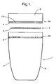
Figure 1 is a partially exploded side elevation of a closure device and vessel according to a preferred embodiment of the invention; -
Figure 2 is a side elevation of the closure device and vessel shown inFig. 1 wherein a valve of the closure device is open; -
Figure 3 is a side elevation of the closure device and vessel shown inFig. 1 wherein a valve of the closure device is closed; -
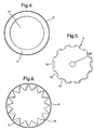
Figure 4 is a top plan view of a valve part; -
Figure 5 is a top plan view of another valve part; -
Figure 6 is a top plan view of further valve part; -
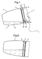
Figure 7 is a side view of the closure device and vessel shown inFig. 1 ; -
Figure 8 is a further side view of the closure device and vessel shown inFig. 1 ; -
Figure 9 is a partially exploded side elevation of a closure device and vessel with a different valve body to that shown inFig. 1 ; -
Figure 10 is a side elevation of a second embodiment of a closure device and vessel according to the invention; -
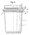
Figure 11 is a side view of a third embodiment of a closure device and vessel according to the invention; -
Figure 12 is a cross-section of a front view of a closure device and vessel shown inFig. 11 in the open position; -
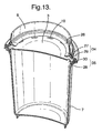
Figure 13 is a cross-section of a perspective view of a closure device and vessel shown inFigs. 11 and12 in the open position; -
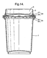
Figure 14 is a cross-section of a front view of a closure device and vessel shown inFigs. 11 to 13 in the closed position; -
Figure 15 is a cross-section of a perspective view of a closure device and vessel shown inFigs. 11 to 14 in the closed position; -
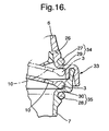
Figure 16 is a cross-sectional view of part of the closure device; -
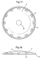
Fig. 17 is a top plan view of a valve part; and -
Fig. 18 is a side view of a valve part. -
Figure 1 shows aclosure device 2 andvessel 1, including amain vessel part 7 for holding a fluid and a removable lid orrim part 6 for direct application to the user's mouth. Therim part 6 is readily removable from the vessel to allow the vessel to be easily filled and/or cleaned, although these operations could be carried out with therim part 6 in place. A push-on flange (not shown) extending around the circumference of the vessel can be used to secure therim part 6 to themain vessel part 7. Alternatively, therim part 6 and themain vessel part 7 can be attached to one another by a threaded connection. - The
closure device 2 comprises a bistable valve including avalve member 3, in the form of a valve disc, and a first and asecond valve seat valve rim portions valve member 3 is movable between the first and secondvalve rim portions valve rim portion 4 is situated above the secondvalve rim portion 5. Therefore, in order to open the valve, a downward force, or a force towards the inside of thevessel 1 is required to act on thevalve member 3, and in order to close the valve, a force in the opposite direction, i.e. away from the inside of thevessel 1 is required. In this way, the valve can be opened by depressing thevalve member 3 when it is desired to drink from thevessel 1. It is possible to arrange thevalve member 3 so that it can be depressed by the user's nose or lip for example when taking a sip from thevessel 1. Advantageously, thevalve member 3 can be constructed as unitary moving part. -
Figure 2 shows theclosure device 2 andvessel 1 ofFigure 1 with thevalve disc 3 in the open position, i.e. engaged with the secondvalve rim portion 5. Thevalve member 3 includes a number ofperforations 10, and thevalve rim portion 5 is dimensioned so thatfluid 9 may flow through gaps defined by the perforations, as shown more clearly inFig. 5 . -
Figure 3 shows theclosure device 2 andvessel 1 ofFigure 1 with thevalve member 3 in the closed position, i.e. engaged with the firstvalve rim portion 4. The dimensions of the firstvalve rim portion 4 are such that the perforations around the periphery of the valve disc are closed off when thevalve member 3 engages with the firstvalve rim portion 4 and so no fluid can escape. - The first and second
valve rim portions valve rim portions valve rim portion 4 to be magnetized to hold thevalve member 3 in the closed position, and to rely on gravity to hold thevalve member 3 against the lowervalve rim portion 5 when the valve is open but such an arrangement is not within the scope of the present invention. Instead of magnetic means for holding thevalve disc 3 in place, mechanical means such as a latching mechanism can be utilised. -
Figure 4 shows the firstvalve rim portion 4 in plan view, nested within therim part 6 of thevessel 1. Thevalve rim portion 4 can be integrally formed with thevessel rim part 6 can be formed separately and affixed thereto. Thevalve rim portion 4 defines a centralcircular aperture 12 through which fluid passes when the valve is open. The valve rim portion may comprise or be at least in part comprised by a gasket or seal. -
Figure 5 shows thevalve member 3 in plan view including theperforations 10 distributed evenly around the periphery of themember 3. Thevalve member 3 may also include apressure releasing means 32, such as a safety valve. -
Figure 6 shows in plan view the secondvalve rim portion 5 nested within thewalls 8 of themain vessel part 7. Preferably, thevalve member 3 is retained more firmly in the closed position than in the open position, to ensure that when the device is closed, it remains closed, until the user decides to open it, and helping to avoid leakage from the vessel. Further, the force required to hold thevalve member 3 in the open position is optimised to make sure that when the user drinks from the vessel, this action does not cause the valve to close, but the force holding the valve open should be weak enough so that if the vessel is knocked over or dropped, thevalve member 3 is pushed into the closed position. One way of achieving this magnetically is to make the secondvalve rim portion 5 magnetically weaker than the firstvalve rim portion 4. In the example shown, this is achieved by forming the secondvalve rim portion 5 with less magnetic material than the firstvalve rim portion 4, in particular using a saw tooth configuration for the secondvalve rim portion 5. Anaperture 13 is defined by the secondvalve rim portion 5 through which fluid may pass when the valve is open. Thevalve member 3 is constructed such that this aperture is not closed whenvalve member 3 is seated onvalve rim portion 5 when the device is in the closed position. - An alternative construction of the valve rim portions, not shown in the drawings, utilises one or more magnetic bands arranged around the inner periphery of the vessel, into which the valve disc can fit, rather than abutting against the valve rim portions as it does in the above embodiment. An additional flange can be provided below and/or above the magnetic band or bands to prevent the valve disc falling out of the closure device.
-
Figure 7 illustrates theclosure device 2 andvessel 1 ofFigure 1 with thevalve member 3 in the open position, wherein the vessel is inclined and a user is drinking therefrom. Arrows A show the path which fluid takes to exit the vessel. Firstly, the fluid passes through theaperture 13 of the secondvalve rim portion 5 and between theperforations 10 of thevalve member 3. The fluid then passes through theaperture 12 defined by the firstvalve rim portion 4 and over thevessel rim part 6 into the user's mouth. - As shown in
Figure 8 , the strength of the magnet in the secondvalve rim portion 5 can be chosen such that if the user inclines the vessel beyond a certain angle to the vertical, depending on the quantity of fluid that is inside themain vessel part 7, thevalve member 3 can move into the closed position under the fluid pressure. Equally, if the device is dropped or knocked over, the fluid pressure will move thevalve member 3 into the closed position. The valve can also be constructed so as to close when a user shakes the vessel. The device can be reopened by simply depressing thevalve member 3. -
Figure 9 shows a variation on thevalve member 3, wherein a dome-shaped protrusion is provided on the upper surface of thevalve member 3. Theprotrusion 14 helps to guide any residue of fluid within the closure device back into themain part 7 of the vessel. Further, theprotrusion 14 can act as a button facilitating the depression of thevalve member 3 by the user. - Preferably, the
surface 8 of themain vessel part 7 has a curved surface profile. By virtue of this feature, fluid currents occurring when the vessel is knocked over are damped, which reduces the amount of water escaping through the valve before it actually seals shut. -
Figure 10 shows a different embodiment of the closure device, wherein the valve member comprises first and secondmotion limiting elements valve seat 25 which comprises avalve rim portion 24. The firstmotion limiting element 22 is arranged above the secondmotion limiting element 23 when the vessel is upright, and in the open position of the valve, the first motion limiting element engages thevalve rim portion 24. The second motion limiting element is arranged below the first motion limiting element, and in the closed position of the valve engages thevalve rim portion 24. - The first
motion restricting element 22 includes a series of perforations around its periphery, which allow fluid to pass therethrough when the firstmotion restricting element 22 is in contact with thevalve rim portion 24. - The device according to
Figure 10 works in much the same way as the device shown inFigures. 1 to 9 , with the difference that instead of providing two valve rim portions and a valve member, preferably in the form of a flat valve disc, there is only one valve rim portion and two disc elements on the valve member. The two disc elements can be connected to one another by aspindle 21. -
Figure 11 shows a further embodiment of the closure device according to the invention, including amain vessel part 7 for holding the fluid and arim part 6 which forms an upper lid of the vessel. Therim part 6 is readily removable from the vessel to allow the vessel to be easily filled with fluid and/or cleaned, although these operations could be carried out with the rim part in place. - The
closure device 2 comprises a bistable valve with a valve member 3 (not shown inFigure 11 ) and first and second valve seats 34,35. Thefirst valve seat 34 is comprised by therim part 6 and thesecond valve seat 35 is comprised by themain vessel part 7. The closure device also comprises a seal orgasket 26 which closes the path which fluid would take to exit the vessel when the valve is in the closed position. Theseal 26 forms an important component of thefirst valve portion 4. The operation of the device will be further explained with reference toFigs. 12 to 17 . -
Figure 12 shows a cross-sectional perspective view of the closure device seen inFigure 11 in the open position. - The
valve member 3 is held in position against thesecond valve seat 35.Valve seat 35 is comprised of aring 28, located at least partially in a groove which extends around the circumference of the exterior of themain vessel 7. It is alternatively envisioned that thefirst valve seat 34 is located on themain vessel part 7 or that thesecond valve seat 35 is located on therim part 6 however this is not shown in the drawings.Valve seat 35 also comprises a valve rim orflange 29 against which thevalve member 3 abuts when in the closed position. Therim 29 is formed at least partially around an inner circumference of an interior part of thevessel 1.Rim 29 defines a lower limit stop which derives a maximum extent of movement forvalve member 3. -
Valve member 3 is held in the closed position by means of a magnetic force.Ring 28 can be comprised by a material which is attracted to magnets, such as steel. In this case,valve member 3 is comprised by or comprises a material which exerts a magnetic force of attraction towardsring 28. Alternatively, thering 28 could also comprise or be comprised by a material which is also capable of generating a magnetic force of attraction. In this case, thevalve member 3 may instead be comprised of a material which is attracted by a magnetic force, or may also be comprised of a magnetic material which generates a magnetic force of attraction. - The magnetic attraction between the
ring 28 andvalve member 3 is present, even though thevalve rim portion 30 is arranged between thering 28 and thevalve member 3. An advantage of therings vessel 1 is that they do not come into contact with fluid inside thevessel 1. - If the vessel is knocked over, the inside fluid will be knocked onto the
valve member 3 and the force of the fluid on the member will act against the magnetic force of attraction between thering 28 and thevalve member 3. The size of the attractive force is such that if a user drinks from the cup, the fluid force on the valve member is not great enough to overcome the magnetic force of attraction, but if the cup is knocked over, the force will be great enough to overcome the attractive force and move the valve member from thevalve seat 35 towards theopposite valve seat 34. -
Figure 13 shows a perspective view of the closure device in the open position, as seen inFigure. 12 . Fluid can flow out of the vessel, for example when a user wishes to drink from the vessel, sincevalve member 3 comprises a number ofperforations 10, located around the periphery of thevalve member 3 through which fluid can flow. The part ofvalve member 3 which is in contact with thevalve seat 35 does not include theperforations 10 so fluid flow is unobstructed. -
Figure 14 shows the device in the closed position.Valve member 3 is held in position against thefirst valve seat 34 by a magnetic force of attraction betweenvalve ring 27 andvalve member 3.Valve seat 34 can have the same properties or features as previously described in relation tovalve seat 35. Valve rim orflange 29 is formed by an inner part of thevalve rim 6 against whichvalve member 3 engages when held in the closed position. Alternatively, thefirst valve seat 34 could be arranged in the main vessel 7 (not shown) as long as the first valve seat is located above the second valve seat when the vessel is in the upright position. - The closure device comprises a seal or
gasket 26 located above thefirst valve seat 34. The seal is arranged such that when the valve member is in the closed position, theperforations 10 in thevalve member 3 are covered by the seal such that fluid paths out of the vessel are closed. It is alternatively envisioned that the seal could only partially cover the perforations (not shown) so that in the closed position, a level of flow can still exit the vessel. A comparison ofFigures 13 and15 shows that when the closure device is in the open position (Figure 13 ) theperforations 10 in thevalve member 3 are unobstructed so fluid can exit thevessel 1. InFigure 15 , theseal 26 covers the perforations so fluid cannot exit thevessel 1. -
Figure 16 provides a zoomed-in view of part of a cross-section of the closing device. -
Valve member 3 is seen in both the open and the closed positions, with the member shown in dotted lines in the closed position. In the open position,valve member 3 rests on thesecond valve rim 30. The magnetic force of attraction between the valve member and thering 28 holds the valve member in position. Fluid can leave the vessel throughperforations 10, at the circumferential location indicated on the figure. In the open position,valve member 3 abuts thefirst valve rim 29. The magnetic force of attraction between thevalve member 3 and thering 27 holds the valve member in the open position.Seal 26 is located above thefirst valve seat 34 and engages with thevalve member 3, blocking the path which fluid could otherwise take from the interior of themain vessel part 7 out of the vessel. - The
vessel 1 is shown to be comprised by a room orlid part 6, secured to themain vessel part 7 by a snap-fit connection 33. Therim part 6 is removable. Other forms of attachment are possible which are not shown here, such as a threaded connection. - To open the vessel from the closed position seen in
Figures 14 and15 , a user can apply a force tovalve member 3 through anaperture 12 in the top of the vessel which allows a user access to thevalve member 3. Thevalve member 3 can be pushed by a user towards the open position where it sits against thesecond valve seat 35, if the user pushes hard enough to overcome the magnetic force of attraction between thevalve member 3 and thering 27. The direction in which a user would push to open the closure device is indicated by an arrow onFigure 15 . - The
valve body 3 could be retained more firmly in the open position than the closed position. This could be achieved by having a lesser thickness of theinner rim 28 than theinner rim 29. -
Figure 17 illustrates thevalve member 3 ofFigures 11 to 15 in the form of a disc.Perforations 10 are equally spaced around an outer circumference of the disc within a main area of the disc. An irregular spacing of the perforations is also possible. Thevalve member 3 also has a raisedrim 31 surrounding the periphery of the disc which abuts against the first and secondvalve rim portions valve member 3 can be made of a plastics material impregnated by magnets. A pressure-releasingmeans 32 can be located on the disc. This member could be located off-centre of the valve member alternatively (not shown). This means may be a safety valve. -
Figure 18 also illustrates the valve body. The raisedrim 31 can be seen as well as aprotrusion 14 on the upper surface of the disc. The protrusion is dome-shaped. - It is possible to provide a locking position of the closure device, in which the valve is locked open or closed. This can be effected using lugs within the closure device which can lock the valve body in place for example by rotating the valve body into engagement with the lugs.
- The closure device may also be fully located within the rim part,wherein the rim part forms an upper lid of a vessel, removable from the main vessel.
- The vessel may comprise, at least in part, a flexible material which expands when a hot fluid is located within the vessel. The sides of the main vessel could take a concertina-like form to permit this expansion. The sealing properties of the valve will not be compromised by such an arrangement.
- Alternatively, or in addition to part of the vessel comprising a flexible material, the vessel may comprise a means of relieving pressure within the container when a hot fluid is sealed within the vessel. A wide variety of such means is known and may include, for example, a safety valve located on the closure device or vessel. The safety valve may be located on the valve disc itself. The safety valve may, for example, be a silicon safety valve.
- Features disclosed in the context of each of the figures can also be combined to form other embodiments not illustrated here within the scope of protection defined by the claims.
- References herein to fluid are intended to cover any substance which can be placed in the vessel and poured therefrom, including for example liquids and powders or granulated substances.
- In embodiments of the present invention such as those described above, it will be appreciated that the magnetic force attracting the valve member to a valve seat may be generated by using a magnetic material (which produces a magnetic field) in the manufacture of the valve member. The valve seats may then be made of a material attracted by a magnet, such as steel. The valve seats may themselves be made of a magnetic material, in which case the valve member need not then be of a magnetic material but merely of a material attracted by a magnetic force (such as steel).
- In use of the present invention, it should also be understood that a vessel may be filled or refilled with the valve member initially in the closed position and without removing a closure of the vessel. The liquid (or other pourable material, such as granulated solids) to be used in filling the vessel may be poured onto the top of the valve member so that the weight of the liquid overcomes the force retaining the valve member in the closed position and moves the valve member to the open position thereby allowing access to the interior of the vessel. The liquid may then flow into the interior of the vessel. This feature is particularly useful in topping-up drinks containers.
Claims (15)
- A closure device (2) for a fluid vessel (1), the closure device (2) comprising a bistable valve having a valve member (3) having an open position in which fluid can exit the vessel and a closed position in which fluid is substantially prevented from exiting the vessel, characterised in that the closure device (2) comprises a means for exerting a force on the valve member (3) which holds the valve member (3) in the open position and in that the bistable valve is arranged to close in response to fluid inside the vessel pressing against the valve member (3) so as to overcome the force exerted by said means.
- A closure device according to claim 1, further comprising a first and a second valve seat (34,35), wherein the valve member (3) engages with the first valve seat (34) when in the closed position and the valve member (3) engages with the second valve seat (35) when in the open position.
- A closure device according to claim 2, wherein the first valve seat (34) is above the second valve seat (35) when the vessel is upright and wherein the first valve seat (34) delimits the closed position of the valve, and the second valve seat (35) delimits the open position of the valve.
- A closure device according to any one of the preceding claims, wherein the force which holds the valve member (3) in the open position is a magnetic force.
- A closure device according to any one of the preceding claims, wherein the valve member (3) is retained in the closed position by means of a magnetic force.
- A closure device according to any one of claims 2 to 5, wherein the first valve seat (34) is located on a removable lid (6) of a vessel (1) and the second valve seat (35) is located on a main part of a vessel (1) which can contain fluid.
- A closure device according to any one of claims 2 to 6 wherein the first valve seat (34) comprises a first valve rim portion (4,29) and the second valve seat (35) comprises a second valve rim portion (5,30) and the valve member (3) can engage with the first and second valve rim portions (4,29,5,30), and preferably each valve rim portion (4,29,5,30) is formed from an inwardly extending part which is formed, at least in part, around an inner circumference of the vessel (1) and preferably the valve rim portion (4,29,5,30) is formed by part of the vessel.
- A closure device according to any one of the preceding claims, wherein the closure device comprises a gasket (26) against which the valve member (3) is sealingly engageable.
- A closure device according to any one of the preceding claims, wherein a greater force is required to move the valve member (3) from the closed position than is required to move the valve member from the open position.
- A closure device according to any one of the preceding claims, wherein the valve member (3) comprises a disc.
- A closure device according to claim 10, wherein the disc comprises a plastics material, impregnated by magnetic material.
- A closure device according to any one of the preceding claims, wherein the valve member comprises a dome-like raised protrusion (14) on an upper surface of the valve member (3).
- A closure device according to claim 7, wherein in the open position, an opening is defined between the valve member (3) and the second valve rim portion which extends substantially around the circumference of the vessel.
- A closure device according to any one of the preceding claims, wherein the device comprises a means of releasing pressure (32) within the vessel (1) and the means is preferably a safety valve.
- A fluid vessel comprising a closure device according to any one of the preceding claims.
Priority Applications (1)
| Application Number | Priority Date | Filing Date | Title |
|---|---|---|---|
| PL08788244T PL2182827T3 (en) | 2007-07-31 | 2008-07-31 | Closure device for a fluid vessel |
Applications Claiming Priority (2)
| Application Number | Priority Date | Filing Date | Title |
|---|---|---|---|
| GB0714968.5A GB2451493B (en) | 2007-07-31 | 2007-07-31 | Closure device for a fluid vessel |
| PCT/GB2008/002610 WO2009016380A1 (en) | 2007-07-31 | 2008-07-31 | Closure device for a fluid vessel |
Publications (2)
| Publication Number | Publication Date |
|---|---|
| EP2182827A1 EP2182827A1 (en) | 2010-05-12 |
| EP2182827B1 true EP2182827B1 (en) | 2012-11-21 |
Family
ID=38529104
Family Applications (1)
| Application Number | Title | Priority Date | Filing Date |
|---|---|---|---|
| EP08788244A Active EP2182827B1 (en) | 2007-07-31 | 2008-07-31 | Closure device for a fluid vessel |
Country Status (15)
| Country | Link |
|---|---|
| US (2) | US8931654B2 (en) |
| EP (1) | EP2182827B1 (en) |
| JP (2) | JP5832745B2 (en) |
| CN (1) | CN101808552B (en) |
| AU (1) | AU2008281560B2 (en) |
| CA (1) | CA2731441C (en) |
| ES (1) | ES2398763T3 (en) |
| GB (1) | GB2451493B (en) |
| MY (1) | MY152351A (en) |
| NZ (1) | NZ583618A (en) |
| PL (1) | PL2182827T3 (en) |
| PT (1) | PT2182827E (en) |
| RU (1) | RU2472412C2 (en) |
| WO (1) | WO2009016380A1 (en) |
| ZA (1) | ZA201001386B (en) |
Families Citing this family (48)
| Publication number | Priority date | Publication date | Assignee | Title |
|---|---|---|---|---|
| US8317048B2 (en) * | 2008-08-11 | 2012-11-27 | Louis Hajichristou | Self-actuating closure mechanisms for closable articles |
| US8881938B2 (en) | 2012-08-08 | 2014-11-11 | Harl-Bella Holdings, Llc | Lid for beverage container |
| TW201429815A (en) * | 2013-01-31 | 2014-08-01 | Rong-Rong Tian | Beverage container allowing for making both cold beverage and hot beverage |
| USD756773S1 (en) | 2013-08-08 | 2016-05-24 | Harl-Bella Holdings, Llc | Lid with tear line |
| USD737142S1 (en) | 2013-08-08 | 2015-08-25 | Harl-Bella Holdings, Llc | Lid with triangular shaped basin |
| USD739729S1 (en) | 2013-08-08 | 2015-09-29 | Harl-Bella Holdings, Llc | Lid for beverage container |
| USD736623S1 (en) | 2013-08-08 | 2015-08-18 | Harl-Bella Holdings, Llc | Lid with egg shaped basin |
| US20150375913A1 (en) * | 2014-06-30 | 2015-12-31 | Julia A. Brandsdorfer | Drink container adapter |
| USD784072S1 (en) | 2015-01-30 | 2017-04-18 | Magecup Limited | Lid for a beverage container |
| USD808218S1 (en) | 2015-08-31 | 2018-01-23 | Yeti Coolers, Llc | Container |
| USD751338S1 (en) | 2015-11-04 | 2016-03-15 | Yeti Coolers, Llc | Lid |
| USD804905S1 (en) | 2015-08-31 | 2017-12-12 | Yeti Coolers, Llc | Container |
| USD751341S1 (en) | 2015-11-04 | 2016-03-15 | Yeti Coolers, Llc | Lid |
| US10034580B2 (en) | 2015-10-05 | 2018-07-31 | Yeti Coolers, Llc | Container and handle and method of forming a container and handle |
| DK4032441T3 (en) | 2015-10-30 | 2023-10-09 | Yeti Coolers Llc | CLOSURE AND LID AND METHOD OF FORMING CLOSURE AND LID |
| US10232993B2 (en) | 2015-10-30 | 2019-03-19 | Yeti Coolers, Llc | Closure and lid and method of forming closure and lid |
| US10232992B2 (en) | 2015-10-30 | 2019-03-19 | Yeti Coolers, Llc | Closure and lid and method of forming closure and lid |
| WO2017083973A1 (en) * | 2015-11-16 | 2017-05-26 | Abdiye Abbey | Lid for beverage containers |
| MX2018006448A (en) | 2015-11-25 | 2018-11-09 | Handi Craft Co | Spoutless drinking cup. |
| USD775495S1 (en) * | 2016-03-01 | 2017-01-03 | Thermos L.L.C. | Bottle |
| USD812989S1 (en) | 2016-05-06 | 2018-03-20 | Yeti Coolers, Llc | Handle |
| USD812988S1 (en) | 2016-05-06 | 2018-03-20 | Yeti Coolers, Llc | Handle |
| USD812985S1 (en) | 2016-05-06 | 2018-03-20 | Yeti Coolers, Llc | Handle |
| USD814242S1 (en) | 2016-05-06 | 2018-04-03 | Yeti Coolers, Llc | Container |
| USD813605S1 (en) | 2016-05-06 | 2018-03-27 | Yeti Coolers, Llc | Container |
| USD812432S1 (en) | 2016-05-06 | 2018-03-13 | Yeti Coolers, Llc | Container |
| USD812984S1 (en) | 2016-05-06 | 2018-03-20 | Yeti Coolers, Llc | Handle |
| USD812979S1 (en) | 2016-05-06 | 2018-03-20 | Yeti Coolers, Llc | Container |
| USD812987S1 (en) | 2016-05-06 | 2018-03-20 | Yeti Coolers, Llc | Handle |
| USD820046S1 (en) | 2016-05-06 | 2018-06-12 | Yeti Coolers, Llc | Container |
| USD812986S1 (en) | 2016-05-06 | 2018-03-20 | Yeti Coolers, Llc | Handle |
| US20170367511A1 (en) * | 2016-06-24 | 2017-12-28 | Richard Dean Neff | Self chilling beverage system |
| USD815893S1 (en) | 2016-10-07 | 2018-04-24 | Yeti Coolers, Llc | Lid |
| USD824212S1 (en) | 2016-10-07 | 2018-07-31 | Yeti Coolers, Llc | Lid |
| JP6993758B2 (en) * | 2016-11-08 | 2022-01-14 | エーエフジェイ インダストリーズ エルエルシー | Container with automatic closure lid |
| USD820044S1 (en) | 2016-11-15 | 2018-06-12 | Plan D Partners, Inc. | Drinking cup with lid |
| CN107198407B (en) | 2017-07-21 | 2019-03-15 | 京东方科技集团股份有限公司 | Anti-watering cup and its control method |
| WO2019156709A1 (en) * | 2018-02-06 | 2019-08-15 | Edgewell Personal Care Brands, Llc | Training cup |
| FI3855982T3 (en) | 2018-10-23 | 2023-11-20 | Yeti Coolers Llc | Closure and lid and method of forming closure and lid |
| USD873617S1 (en) * | 2018-12-03 | 2020-01-28 | b.box for kids developments Pty Ltd. | Drinking cup |
| GB201904882D0 (en) * | 2019-04-05 | 2019-05-22 | Magecup Ltd | Fluid vessel closure device |
| USD914455S1 (en) * | 2019-08-07 | 2021-03-30 | Real Value LLC | Tumbler |
| USD982973S1 (en) | 2019-10-09 | 2023-04-11 | Yeti Coolers, Llc | Tumbler |
| USD964102S1 (en) | 2019-10-09 | 2022-09-20 | Yeti Coolers, Llc | Tumbler |
| USD1011883S1 (en) | 2020-02-12 | 2024-01-23 | Magecup Limited | Lid for a drinking vessel |
| USD982982S1 (en) | 2020-10-01 | 2023-04-11 | Yeti Coolers, Llc | Tumbler |
| USD977912S1 (en) | 2020-10-01 | 2023-02-14 | Yeti Coolers, Llc | Tumbler |
| USD988797S1 (en) * | 2021-01-15 | 2023-06-13 | Brumate Inc. | Beverage container with lid |
Family Cites Families (35)
| Publication number | Priority date | Publication date | Assignee | Title |
|---|---|---|---|---|
| US1254251A (en) * | 1917-05-16 | 1918-01-22 | Rollo Morris Magnus | Drinking-weir. |
| US2675815A (en) * | 1952-10-13 | 1954-04-20 | Wallace S Dale | Antispill child's drinking cup with magnetic closure valve |
| US3360161A (en) * | 1965-10-21 | 1967-12-26 | Marlin B Smith | Splashproof drinking vessel |
| US3730399A (en) * | 1972-02-22 | 1973-05-01 | Nospital Ltd | Non-spill drinking cup top |
| US4130215A (en) * | 1978-02-10 | 1978-12-19 | Corey Joe F | No spill beverage cup |
| US4394928A (en) * | 1980-04-22 | 1983-07-26 | Morris Philip | Splash-proof container and cover |
| EP0296618B1 (en) * | 1987-06-25 | 1990-12-05 | Temtec Fahrzeugtechnik Entwicklungsgesellschaft mbH | Self-closing fuel tank seal |
| US4942976A (en) * | 1988-10-17 | 1990-07-24 | Tapour, Inc. | Container closure with spigot valve |
| IT1247132B (en) * | 1991-03-05 | 1994-12-12 | Guala Spa | CLOSING DEVICE FOR BOTTLES, ESPECIALLY INTENDED FOR BOTTLES FOR PRECIOUS BEVERAGES. |
| GB2264109A (en) * | 1992-01-30 | 1993-08-18 | Joel Matthew Sciamma | Liquid dispenser with magnetically operated valve |
| WO1994014588A1 (en) * | 1992-12-22 | 1994-07-07 | Sdt Technologies, Inc. | Closure for dispensing produce from a container |
| US5249703A (en) * | 1993-03-26 | 1993-10-05 | Morry Karp | Travel mug |
| US5540350A (en) * | 1995-02-16 | 1996-07-30 | Mallory Industries Inc. | Splash/slosh guard for drinking vessels |
| US5979689A (en) * | 1995-02-16 | 1999-11-09 | Lansky; Daryl J. | Splash/slosh guard for drinking vessels |
| RU95106855A (en) * | 1995-04-28 | 1996-12-10 | С.П. Львов | Collapsible container for liquid |
| US5573139A (en) * | 1995-07-05 | 1996-11-12 | Yeh; Frank | Drinking mug with lid and mug body formed from one piece |
| JPH1029657A (en) | 1996-07-16 | 1998-02-03 | Hiroshi Nakahata | Container for humidifying |
| GB9717595D0 (en) * | 1997-08-21 | 1997-10-22 | Metal Box Plc | Valves for packaging containers |
| CN2390508Y (en) * | 1999-09-17 | 2000-08-09 | 吴凤君 | Insulation cup |
| DE60009445T2 (en) * | 2000-02-28 | 2005-03-24 | Guala Closures S.P.A. | Safety closure for bottles for liqueur or the like |
| US6305571B1 (en) * | 2000-06-07 | 2001-10-23 | Donny Chu | Lid device with splashless baffle |
| WO2001097663A1 (en) | 2000-06-23 | 2001-12-27 | Sybre Limited | Spill proof closure and cup |
| US6488173B2 (en) * | 2000-07-06 | 2002-12-03 | Michael Milan | Beverage container lid having baffle arrangement for liquid cooling |
| US6702145B2 (en) * | 2000-09-26 | 2004-03-09 | Alexander R. Malcolm | Splash-proof lid for a cup |
| US6805266B2 (en) * | 2001-06-04 | 2004-10-19 | Av Doron | Safety device for a liquid-containing vessel |
| US6749092B2 (en) * | 2001-08-10 | 2004-06-15 | Seaquist Closures Foreign, Inc. | Deformable dispensing valve |
| US7017768B2 (en) * | 2002-05-21 | 2006-03-28 | Randy Jerome Iskierka | Floatable barrier for use with a beverage container |
| CN2598466Y (en) * | 2002-12-18 | 2004-01-14 | 王琨 | Cup |
| US20040232154A1 (en) * | 2003-05-19 | 2004-11-25 | Fort James Corporation | Splash Resistant Lid With a Snap-On Baffle |
| US7100790B2 (en) * | 2004-04-15 | 2006-09-05 | Dark Richard C G | Spill-resistant metered flow cap for a cup |
| JP4633519B2 (en) * | 2005-03-31 | 2011-02-16 | 明治製菓株式会社 | Midecamycin high producing bacteria |
| US20060226146A1 (en) | 2005-04-06 | 2006-10-12 | Haberman Mandy N | Dispensing vessels |
| US7950541B2 (en) * | 2005-07-07 | 2011-05-31 | Chef'n Corporation | Apparatus and method for magnetically sealing a beverage container lid |
| JP4666258B2 (en) * | 2006-01-11 | 2011-04-06 | 横河電機株式会社 | Data access system |
| US7513380B2 (en) * | 2006-01-20 | 2009-04-07 | Robert Canedo | Self closing container |
-
2007
- 2007-07-31 GB GB0714968.5A patent/GB2451493B/en not_active Expired - Fee Related
-
2008
- 2008-07-31 RU RU2010107206/12A patent/RU2472412C2/en not_active IP Right Cessation
- 2008-07-31 ES ES08788244T patent/ES2398763T3/en active Active
- 2008-07-31 MY MYPI20100485 patent/MY152351A/en unknown
- 2008-07-31 PT PT87882445T patent/PT2182827E/en unknown
- 2008-07-31 NZ NZ583618A patent/NZ583618A/en not_active IP Right Cessation
- 2008-07-31 US US12/452,993 patent/US8931654B2/en not_active Expired - Fee Related
- 2008-07-31 WO PCT/GB2008/002610 patent/WO2009016380A1/en active Application Filing
- 2008-07-31 CN CN2008801104551A patent/CN101808552B/en active Active
- 2008-07-31 JP JP2010518737A patent/JP5832745B2/en not_active Expired - Fee Related
- 2008-07-31 PL PL08788244T patent/PL2182827T3/en unknown
- 2008-07-31 CA CA2731441A patent/CA2731441C/en active Active
- 2008-07-31 EP EP08788244A patent/EP2182827B1/en active Active
- 2008-07-31 AU AU2008281560A patent/AU2008281560B2/en not_active Ceased
-
2010
- 2010-02-25 ZA ZA2010/01386A patent/ZA201001386B/en unknown
-
2014
- 2014-05-23 JP JP2014107213A patent/JP2014177309A/en active Pending
- 2014-12-10 US US14/565,620 patent/US20150090714A1/en not_active Abandoned
Also Published As
| Publication number | Publication date |
|---|---|
| ZA201001386B (en) | 2011-08-31 |
| GB2451493A (en) | 2009-02-04 |
| CA2731441A1 (en) | 2009-02-05 |
| US20150090714A1 (en) | 2015-04-02 |
| RU2010107206A (en) | 2011-09-20 |
| MY152351A (en) | 2014-09-15 |
| PT2182827E (en) | 2013-02-04 |
| RU2472412C2 (en) | 2013-01-20 |
| CA2731441C (en) | 2015-10-20 |
| JP2014177309A (en) | 2014-09-25 |
| CN101808552B (en) | 2013-08-14 |
| GB2451493B (en) | 2011-12-14 |
| NZ583618A (en) | 2011-12-22 |
| PL2182827T3 (en) | 2013-04-30 |
| GB0714968D0 (en) | 2007-09-12 |
| US8931654B2 (en) | 2015-01-13 |
| CN101808552A (en) | 2010-08-18 |
| JP2010535139A (en) | 2010-11-18 |
| ES2398763T3 (en) | 2013-03-21 |
| EP2182827A1 (en) | 2010-05-12 |
| AU2008281560B2 (en) | 2014-12-11 |
| AU2008281560A1 (en) | 2009-02-05 |
| ES2398763T8 (en) | 2013-04-22 |
| WO2009016380A1 (en) | 2009-02-05 |
| US20100206874A1 (en) | 2010-08-19 |
| JP5832745B2 (en) | 2015-12-16 |
Similar Documents
| Publication | Publication Date | Title |
|---|---|---|
| EP2182827B1 (en) | Closure device for a fluid vessel | |
| JP7422197B2 (en) | portable beverage containers | |
| EP3083430B1 (en) | Sealing mechanism for beverage container | |
| US5497917A (en) | Cap for a beverage server | |
| JP6118332B2 (en) | Closed assembly for drinking cup | |
| US5607073A (en) | Valve | |
| US9016518B2 (en) | Beverage dispensing flow control device and method thereof | |
| US8418876B2 (en) | Valve arrangement | |
| JP4868401B2 (en) | Beverage container | |
| US6648183B2 (en) | Cap for a beverage server | |
| EP3470346A1 (en) | Tiltable lid assembly | |
| CN113795177A (en) | Fluid container closure | |
| CA2060005A1 (en) | Spill-proof lid for beverage cup |
Legal Events
| Date | Code | Title | Description |
|---|---|---|---|
| PUAI | Public reference made under article 153(3) epc to a published international application that has entered the european phase |
Free format text: ORIGINAL CODE: 0009012 |
|
| 17P | Request for examination filed |
Effective date: 20100224 |
|
| AK | Designated contracting states |
Kind code of ref document: A1 Designated state(s): AT BE BG CH CY CZ DE DK EE ES FI FR GB GR HR HU IE IS IT LI LT LU LV MC MT NL NO PL PT RO SE SI SK TR |
|
| AX | Request for extension of the european patent |
Extension state: AL BA MK RS |
|
| DAX | Request for extension of the european patent (deleted) | ||
| RAP1 | Party data changed (applicant data changed or rights of an application transferred) |
Owner name: MAGICUP MARKETING LIMITED |
|
| GRAP | Despatch of communication of intention to grant a patent |
Free format text: ORIGINAL CODE: EPIDOSNIGR1 |
|
| RIN1 | Information on inventor provided before grant (corrected) |
Inventor name: HUMPHREY, STEWART Inventor name: PARSONS, DARREN Inventor name: LE MASURIER, STEVEN |
|
| GRAS | Grant fee paid |
Free format text: ORIGINAL CODE: EPIDOSNIGR3 |
|
| GRAA | (expected) grant |
Free format text: ORIGINAL CODE: 0009210 |
|
| AK | Designated contracting states |
Kind code of ref document: B1 Designated state(s): AT BE BG CH CY CZ DE DK EE ES FI FR GB GR HR HU IE IS IT LI LT LU LV MC MT NL NO PL PT RO SE SI SK TR |
|
| REG | Reference to a national code |
Ref country code: GB Ref legal event code: FG4D |
|
| REG | Reference to a national code |
Ref country code: CH Ref legal event code: EP |
|
| REG | Reference to a national code |
Ref country code: AT Ref legal event code: REF Ref document number: 584607 Country of ref document: AT Kind code of ref document: T Effective date: 20121215 |
|
| REG | Reference to a national code |
Ref country code: IE Ref legal event code: FG4D |
|
| REG | Reference to a national code |
Ref country code: DE Ref legal event code: R096 Ref document number: 602008020292 Country of ref document: DE Effective date: 20130117 |
|
| REG | Reference to a national code |
Ref country code: CH Ref legal event code: NV Representative=s name: ISLER AND PEDRAZZINI AG, CH |
|
| REG | Reference to a national code |
Ref country code: PT Ref legal event code: SC4A Free format text: AVAILABILITY OF NATIONAL TRANSLATION Effective date: 20130128 |
|
| REG | Reference to a national code |
Ref country code: SE Ref legal event code: TRGR |
|
| REG | Reference to a national code |
Ref country code: CH Ref legal event code: NV Representative=s name: ISLER AND PEDRAZZINI AG, CH |
|
| REG | Reference to a national code |
Ref country code: NL Ref legal event code: T3 |
|
| REG | Reference to a national code |
Ref country code: ES Ref legal event code: FG2A Ref document number: 2398763 Country of ref document: ES Kind code of ref document: T3 Effective date: 20130321 |
|
| REG | Reference to a national code |
Ref country code: LT Ref legal event code: MG4D |
|
| PG25 | Lapsed in a contracting state [announced via postgrant information from national office to epo] |
Ref country code: NO Free format text: LAPSE BECAUSE OF FAILURE TO SUBMIT A TRANSLATION OF THE DESCRIPTION OR TO PAY THE FEE WITHIN THE PRESCRIBED TIME-LIMIT Effective date: 20130221 Ref country code: FI Free format text: LAPSE BECAUSE OF FAILURE TO SUBMIT A TRANSLATION OF THE DESCRIPTION OR TO PAY THE FEE WITHIN THE PRESCRIBED TIME-LIMIT Effective date: 20121121 Ref country code: LT Free format text: LAPSE BECAUSE OF FAILURE TO SUBMIT A TRANSLATION OF THE DESCRIPTION OR TO PAY THE FEE WITHIN THE PRESCRIBED TIME-LIMIT Effective date: 20121121 |
|
| REG | Reference to a national code |
Ref country code: PL Ref legal event code: T3 |
|
| PG25 | Lapsed in a contracting state [announced via postgrant information from national office to epo] |
Ref country code: SI Free format text: LAPSE BECAUSE OF FAILURE TO SUBMIT A TRANSLATION OF THE DESCRIPTION OR TO PAY THE FEE WITHIN THE PRESCRIBED TIME-LIMIT Effective date: 20121121 Ref country code: GR Free format text: LAPSE BECAUSE OF FAILURE TO SUBMIT A TRANSLATION OF THE DESCRIPTION OR TO PAY THE FEE WITHIN THE PRESCRIBED TIME-LIMIT Effective date: 20130222 Ref country code: LV Free format text: LAPSE BECAUSE OF FAILURE TO SUBMIT A TRANSLATION OF THE DESCRIPTION OR TO PAY THE FEE WITHIN THE PRESCRIBED TIME-LIMIT Effective date: 20121121 |
|
| PG25 | Lapsed in a contracting state [announced via postgrant information from national office to epo] |
Ref country code: EE Free format text: LAPSE BECAUSE OF FAILURE TO SUBMIT A TRANSLATION OF THE DESCRIPTION OR TO PAY THE FEE WITHIN THE PRESCRIBED TIME-LIMIT Effective date: 20121121 Ref country code: SK Free format text: LAPSE BECAUSE OF FAILURE TO SUBMIT A TRANSLATION OF THE DESCRIPTION OR TO PAY THE FEE WITHIN THE PRESCRIBED TIME-LIMIT Effective date: 20121121 Ref country code: CZ Free format text: LAPSE BECAUSE OF FAILURE TO SUBMIT A TRANSLATION OF THE DESCRIPTION OR TO PAY THE FEE WITHIN THE PRESCRIBED TIME-LIMIT Effective date: 20121121 Ref country code: BG Free format text: LAPSE BECAUSE OF FAILURE TO SUBMIT A TRANSLATION OF THE DESCRIPTION OR TO PAY THE FEE WITHIN THE PRESCRIBED TIME-LIMIT Effective date: 20130221 Ref country code: DK Free format text: LAPSE BECAUSE OF FAILURE TO SUBMIT A TRANSLATION OF THE DESCRIPTION OR TO PAY THE FEE WITHIN THE PRESCRIBED TIME-LIMIT Effective date: 20121121 |
|
| PG25 | Lapsed in a contracting state [announced via postgrant information from national office to epo] |
Ref country code: RO Free format text: LAPSE BECAUSE OF FAILURE TO SUBMIT A TRANSLATION OF THE DESCRIPTION OR TO PAY THE FEE WITHIN THE PRESCRIBED TIME-LIMIT Effective date: 20121121 |
|
| PLBE | No opposition filed within time limit |
Free format text: ORIGINAL CODE: 0009261 |
|
| STAA | Information on the status of an ep patent application or granted ep patent |
Free format text: STATUS: NO OPPOSITION FILED WITHIN TIME LIMIT |
|
| 26N | No opposition filed |
Effective date: 20130822 |
|
| PG25 | Lapsed in a contracting state [announced via postgrant information from national office to epo] |
Ref country code: HR Free format text: LAPSE BECAUSE OF FAILURE TO SUBMIT A TRANSLATION OF THE DESCRIPTION OR TO PAY THE FEE WITHIN THE PRESCRIBED TIME-LIMIT Effective date: 20121121 |
|
| REG | Reference to a national code |
Ref country code: DE Ref legal event code: R097 Ref document number: 602008020292 Country of ref document: DE Effective date: 20130822 |
|
| PG25 | Lapsed in a contracting state [announced via postgrant information from national office to epo] |
Ref country code: MC Free format text: LAPSE BECAUSE OF FAILURE TO SUBMIT A TRANSLATION OF THE DESCRIPTION OR TO PAY THE FEE WITHIN THE PRESCRIBED TIME-LIMIT Effective date: 20121121 |
|
| REG | Reference to a national code |
Ref country code: DE Ref legal event code: R082 Ref document number: 602008020292 Country of ref document: DE Representative=s name: PATENTANWAELTE LIPPERT, STACHOW & PARTNER, DE Ref country code: DE Ref legal event code: R082 Ref document number: 602008020292 Country of ref document: DE Representative=s name: LIPPERT STACHOW PATENTANWAELTE RECHTSANWAELTE , DE |
|
| PG25 | Lapsed in a contracting state [announced via postgrant information from national office to epo] |
Ref country code: MT Free format text: LAPSE BECAUSE OF FAILURE TO SUBMIT A TRANSLATION OF THE DESCRIPTION OR TO PAY THE FEE WITHIN THE PRESCRIBED TIME-LIMIT Effective date: 20121121 Ref country code: CY Free format text: LAPSE BECAUSE OF FAILURE TO SUBMIT A TRANSLATION OF THE DESCRIPTION OR TO PAY THE FEE WITHIN THE PRESCRIBED TIME-LIMIT Effective date: 20121121 |
|
| PG25 | Lapsed in a contracting state [announced via postgrant information from national office to epo] |
Ref country code: HU Free format text: LAPSE BECAUSE OF FAILURE TO SUBMIT A TRANSLATION OF THE DESCRIPTION OR TO PAY THE FEE WITHIN THE PRESCRIBED TIME-LIMIT; INVALID AB INITIO Effective date: 20080731 Ref country code: LU Free format text: LAPSE BECAUSE OF NON-PAYMENT OF DUE FEES Effective date: 20130731 |
|
| PG25 | Lapsed in a contracting state [announced via postgrant information from national office to epo] |
Ref country code: IS Free format text: LAPSE BECAUSE OF FAILURE TO SUBMIT A TRANSLATION OF THE DESCRIPTION OR TO PAY THE FEE WITHIN THE PRESCRIBED TIME-LIMIT Effective date: 20121121 |
|
| REG | Reference to a national code |
Ref country code: FR Ref legal event code: PLFP Year of fee payment: 9 |
|
| REG | Reference to a national code |
Ref country code: GB Ref legal event code: 732E Free format text: REGISTERED BETWEEN 20170223 AND 20170303 |
|
| REG | Reference to a national code |
Ref country code: CH Ref legal event code: PUE Owner name: MAGECUP LIMITED, GB Free format text: FORMER OWNER: MAGICUP MARKETING LIMITED, GB |
|
| REG | Reference to a national code |
Ref country code: NL Ref legal event code: PD Owner name: MAGECUP LIMITED; JE Free format text: DETAILS ASSIGNMENT: CHANGE OF OWNER(S), ASSIGNMENT; FORMER OWNER NAME: MAGICUP MARKETING LIMITED Effective date: 20170313 |
|
| REG | Reference to a national code |
Ref country code: DE Ref legal event code: R082 Ref document number: 602008020292 Country of ref document: DE Representative=s name: LIPPERT STACHOW PATENTANWAELTE RECHTSANWAELTE , DE Ref country code: DE Ref legal event code: R081 Ref document number: 602008020292 Country of ref document: DE Owner name: MAGECUP LTD., JE Free format text: FORMER OWNER: MAGICUP MARKETING LIMITED, WHETSTONE, GB |
|
| REG | Reference to a national code |
Ref country code: FR Ref legal event code: PLFP Year of fee payment: 10 |
|
| REG | Reference to a national code |
Ref country code: AT Ref legal event code: PC Ref document number: 584607 Country of ref document: AT Kind code of ref document: T Owner name: MAGECUP LIMITED, JE Effective date: 20170516 |
|
| REG | Reference to a national code |
Ref country code: ES Ref legal event code: PC2A Owner name: MAGECUP LIMITED Effective date: 20170912 |
|
| REG | Reference to a national code |
Ref country code: FR Ref legal event code: TP Owner name: MAGECUP LIMITED, GB Effective date: 20171011 |
|
| REG | Reference to a national code |
Ref country code: FR Ref legal event code: PLFP Year of fee payment: 11 |
|
| PGFP | Annual fee paid to national office [announced via postgrant information from national office to epo] |
Ref country code: BE Payment date: 20190516 Year of fee payment: 12 Ref country code: NL Payment date: 20190712 Year of fee payment: 12 |
|
| PGFP | Annual fee paid to national office [announced via postgrant information from national office to epo] |
Ref country code: PT Payment date: 20190729 Year of fee payment: 12 Ref country code: TR Payment date: 20190719 Year of fee payment: 12 Ref country code: SE Payment date: 20190710 Year of fee payment: 12 Ref country code: IE Payment date: 20190710 Year of fee payment: 12 Ref country code: IT Payment date: 20190719 Year of fee payment: 12 |
|
| PGFP | Annual fee paid to national office [announced via postgrant information from national office to epo] |
Ref country code: AT Payment date: 20190625 Year of fee payment: 12 |
|
| PGFP | Annual fee paid to national office [announced via postgrant information from national office to epo] |
Ref country code: CH Payment date: 20190718 Year of fee payment: 12 |
|
| PGFP | Annual fee paid to national office [announced via postgrant information from national office to epo] |
Ref country code: ES Payment date: 20200827 Year of fee payment: 13 |
|
| PGFP | Annual fee paid to national office [announced via postgrant information from national office to epo] |
Ref country code: PL Payment date: 20200728 Year of fee payment: 13 |
|
| REG | Reference to a national code |
Ref country code: CH Ref legal event code: PL |
|
| REG | Reference to a national code |
Ref country code: NL Ref legal event code: MM Effective date: 20200801 |
|
| REG | Reference to a national code |
Ref country code: AT Ref legal event code: MM01 Ref document number: 584607 Country of ref document: AT Kind code of ref document: T Effective date: 20200731 |
|
| REG | Reference to a national code |
Ref country code: SE Ref legal event code: EUG |
|
| REG | Reference to a national code |
Ref country code: BE Ref legal event code: MM Effective date: 20200731 |
|
| PG25 | Lapsed in a contracting state [announced via postgrant information from national office to epo] |
Ref country code: PT Free format text: LAPSE BECAUSE OF NON-PAYMENT OF DUE FEES Effective date: 20210302 Ref country code: NL Free format text: LAPSE BECAUSE OF NON-PAYMENT OF DUE FEES Effective date: 20200801 Ref country code: LI Free format text: LAPSE BECAUSE OF NON-PAYMENT OF DUE FEES Effective date: 20200731 Ref country code: CH Free format text: LAPSE BECAUSE OF NON-PAYMENT OF DUE FEES Effective date: 20200731 |
|
| PG25 | Lapsed in a contracting state [announced via postgrant information from national office to epo] |
Ref country code: AT Free format text: LAPSE BECAUSE OF NON-PAYMENT OF DUE FEES Effective date: 20200731 Ref country code: BE Free format text: LAPSE BECAUSE OF NON-PAYMENT OF DUE FEES Effective date: 20200731 Ref country code: SE Free format text: LAPSE BECAUSE OF NON-PAYMENT OF DUE FEES Effective date: 20200801 |
|
| PG25 | Lapsed in a contracting state [announced via postgrant information from national office to epo] |
Ref country code: IE Free format text: LAPSE BECAUSE OF NON-PAYMENT OF DUE FEES Effective date: 20200731 |
|
| PG25 | Lapsed in a contracting state [announced via postgrant information from national office to epo] |
Ref country code: IT Free format text: LAPSE BECAUSE OF NON-PAYMENT OF DUE FEES Effective date: 20200731 |
|
| REG | Reference to a national code |
Ref country code: ES Ref legal event code: FD2A Effective date: 20220930 |
|
| PG25 | Lapsed in a contracting state [announced via postgrant information from national office to epo] |
Ref country code: ES Free format text: LAPSE BECAUSE OF NON-PAYMENT OF DUE FEES Effective date: 20210801 |
|
| PGFP | Annual fee paid to national office [announced via postgrant information from national office to epo] |
Ref country code: FR Payment date: 20230130 Year of fee payment: 15 |
|
| PGFP | Annual fee paid to national office [announced via postgrant information from national office to epo] |
Ref country code: GB Payment date: 20230130 Year of fee payment: 15 Ref country code: DE Payment date: 20230130 Year of fee payment: 15 |
|
| REG | Reference to a national code |
Ref country code: DE Ref legal event code: R119 Ref document number: 602008020292 Country of ref document: DE |
|
| GBPC | Gb: european patent ceased through non-payment of renewal fee |
Effective date: 20230731 |