EP2184590A1 - Dosing device with an exchangeable device for dosing units - Google Patents
Dosing device with an exchangeable device for dosing units Download PDFInfo
- Publication number
- EP2184590A1 EP2184590A1 EP08168761A EP08168761A EP2184590A1 EP 2184590 A1 EP2184590 A1 EP 2184590A1 EP 08168761 A EP08168761 A EP 08168761A EP 08168761 A EP08168761 A EP 08168761A EP 2184590 A1 EP2184590 A1 EP 2184590A1
- Authority
- EP
- European Patent Office
- Prior art keywords
- unit
- dosing
- metering
- base frame
- receiving device
- Prior art date
- Legal status (The legal status is an assumption and is not a legal conclusion. Google has not performed a legal analysis and makes no representation as to the accuracy of the status listed.)
- Granted
Links
Images


Classifications
-
- G—PHYSICS
- G01—MEASURING; TESTING
- G01F—MEASURING VOLUME, VOLUME FLOW, MASS FLOW OR LIQUID LEVEL; METERING BY VOLUME
- G01F13/00—Apparatus for measuring by volume and delivering fluids or fluent solid materials, not provided for in the preceding groups
-
- G—PHYSICS
- G01—MEASURING; TESTING
- G01F—MEASURING VOLUME, VOLUME FLOW, MASS FLOW OR LIQUID LEVEL; METERING BY VOLUME
- G01F11/00—Apparatus requiring external operation adapted at each repeated and identical operation to measure and separate a predetermined volume of fluid or fluent solid material from a supply or container, without regard to weight, and to deliver it
- G01F11/003—Apparatus requiring external operation adapted at each repeated and identical operation to measure and separate a predetermined volume of fluid or fluent solid material from a supply or container, without regard to weight, and to deliver it for fluent solid material
-
- G—PHYSICS
- G01—MEASURING; TESTING
- G01F—MEASURING VOLUME, VOLUME FLOW, MASS FLOW OR LIQUID LEVEL; METERING BY VOLUME
- G01F11/00—Apparatus requiring external operation adapted at each repeated and identical operation to measure and separate a predetermined volume of fluid or fluent solid material from a supply or container, without regard to weight, and to deliver it
- G01F11/006—Details or accessories
-
- G—PHYSICS
- G01—MEASURING; TESTING
- G01F—MEASURING VOLUME, VOLUME FLOW, MASS FLOW OR LIQUID LEVEL; METERING BY VOLUME
- G01F13/00—Apparatus for measuring by volume and delivering fluids or fluent solid materials, not provided for in the preceding groups
- G01F13/001—Apparatus for measuring by volume and delivering fluids or fluent solid materials, not provided for in the preceding groups for fluent solid material
-
- G—PHYSICS
- G01—MEASURING; TESTING
- G01G—WEIGHING
- G01G13/00—Weighing apparatus with automatic feed or discharge for weighing-out batches of material
- G01G13/02—Means for automatically loading weigh pans or other receptacles, e.g. disposable containers, under control of the weighing mechanism
-
- G—PHYSICS
- G01—MEASURING; TESTING
- G01N—INVESTIGATING OR ANALYSING MATERIALS BY DETERMINING THEIR CHEMICAL OR PHYSICAL PROPERTIES
- G01N35/00—Automatic analysis not limited to methods or materials provided for in any single one of groups G01N1/00 - G01N33/00; Handling materials therefor
- G01N35/00584—Control arrangements for automatic analysers
- G01N35/00722—Communications; Identification
- G01N35/00732—Identification of carriers, materials or components in automatic analysers
- G01N2035/00792—Type of components bearing the codes, other than sample carriers
- G01N2035/00811—Type of components bearing the codes, other than sample carriers consumable or exchangeable components other than sample carriers, e.g. detectors, flow cells
Definitions
- the present invention relates to a metering device with a change device for metering units or functional units.
- Dosing devices for powdered or paste-like dosage material are used in particular for dosing small quantities with high precision in small target vessels use. Frequently, such target vessels are placed on a balance in order to weigh the amount of metered product discharged from the metering device, so that this can subsequently be further processed as intended.
- the dosing material is located, for example, in a dosing unit, which essentially has a removal vessel and a dosing head.
- a metering device such as a slider is arranged, which releases an outlet opening, as soon as it is actuated. By means of the outlet opening connected to the removal vessel, the dosage material can subsequently flow into a target vessel arranged below the outlet opening.
- the slider is preferably coupled to a separate from the metering drive device.
- dosing devices of the aforementioned type are also used for producing mixtures of several individual substances.
- a changing device is present, by means of which the individual metering units can be used with the individual substances automatically in the metering device, or can be removed from this.
- the first embodiment has a linearly displaceable holder for a plurality of metering units.
- the second embodiment has a ring-shaped holder, which is arranged rotatably about the metering device.
- the individual dosing units are moved according to their place number in succession, coupled with the drive device and dosed the predetermined amounts of substance according to the recipe in a target vessel.
- the changing device is arranged at a low height above the ground and therefore the area below the changing device can not be used.
- the distance of the outlet opening of a dosing unit to the filling opening of a target vessel located on the weighing pan of the weighing cell should be as small as possible. This is particularly important in the handling of toxic or highly reactive substances of high importance.
- a part of the dosing unit protrudes with its outlet opening arranged at the lower end into the filling opening, so that the inner edge region of the target vessel is not soiled with dosing material. This is with the in the EP 1 959 244 A1 disclosed dosing devices not possible. To achieve this, the entire changing device would have to be adjustable in height.
- the weight of the sum of the usable in the changing device dosing units would have to be moved in the vertical direction up and down.
- the high, too Accordingly, moving mass can also influence the speed of the individual steps during the changeover process of the metering units and lead to increased vibrations.
- the entire space in which the changing device can move must be kept free of other objects and parts of the device. Furthermore, the holder can not be moved during the dosing process.
- the object of the present invention is to provide a metering device whose area requirement, or whose space to be kept free is small and in which a rapid change and rapid loading of metering units or functional units is possible.
- a dosing device has a base frame, at least one receiving device for receiving any dosing unit or functional unit that can be inserted into the receiving device, and at least one drive device. If a dosing unit or functional unit is inserted into the receiving device, this can be coupled to the drive device.
- a holder is arranged in an upper horizontal plane of the base frame and connected to the same. The holder has at least one holding station for a dosing unit or functional unit.
- a load cell is further arranged, which has a load receptor for receiving a target vessel.
- the metering device includes a changing device, by means of which the receiving device is horizontally displaceable relative to the base frame.
- a dosing unit or functional unit can be removed from the holding station by means of the receiving device and accommodated in the receiving device, or removed from the receiving device and accommodated in the holding station.
- the receiving device together with the drive device relative to the base frame, vertically to the filling opening of a target vessel placed on the load receiver, or displaceable from the filling opening of the target vessel to the holding station.
- the changing device thus has at least one horizontal linear guide as a connecting element between the receiving device and the drive device and a vertical linear guide between the unit of drive device and receiving device and the base frame.
- These also include a drive unit for each linear guide and a controller for controlling the drive units.
- the horizontal movements primarily serve the transfer operation of the dosing unit or functional unit between the receiving device and the holding station. However, this does not rule out that the horizontal movement can also serve for subordinate needs, for example the orientation of the dosing unit or functional unit to the target vessel.
- the vertical movements primarily serve to transport the dosing unit or functional unit from the holding station to the target vessel and back again. This precludes, as already explained for horizontal movement, not even that vertical movements for other needs, such as short-stroke unlocking, or locking movements can be used.
- the holder has at least two holding positions and is designed to be linearly displaceable or rotatable relative to the base frame.
- the position of each stopping place is stored in an electronic storage unit of the metering device, so that an operating program executable in a processor module of the metering device finds the desired stopping position and can rotate to a transfer point described below.
- data of the dosing unit used in the holding station can also be stored in this memory unit. If an electronic reading device, for example an RFID reader, is arranged in the region of the holder and the dosing unit has an identification feature, for example an RFID tag, the acquisition of the data of each dosing unit or functional unit can also take place automatically when the holder is fitted with dosing units.
- Such data may be the technical data of the dosing unit, such as the start-up date, the number of doses, the date of the last dose and the like. Further data may relate to the substance filled in the dosing unit, for example its type and composition, its expiry date, its determined parameters relating to the fluidity of the substance and the like.
- the functional units may also have an RFID memory chip on which technical data for the function are stored. If necessary, even usage instructions or even program modules can be retrieved from this memory chip, which influence and / or control individual process steps of the dosing device. Particularly in the case of data acquisition and assembly, the independently movable mounting is of great advantage.
- the holder can be equipped from only one direction and it is only a read-write device necessary to capture the data of all RFID memory chips. Furthermore, as soon as the receiving device has left the upper level, each dosing unit or functional unit located in the holder can be guided past the read / write device at any time and its data can be read or changed.
- the at least one holding place has at least two holding grooves and the receiving device has at least two bearers.
- suitable support points and guide rails which are suitable for the support grooves are formed on the dosing unit or functional unit with the supports.
- the retaining grooves, Support points, support and guide rails extend in their longitudinal direction preferably parallel to each other and parallel to the horizontal movement of the changing device.
- the carriers of the receiving device preferably engage in the holding station. This is possible if the dosing unit or functional unit is arranged between a vertically arranged inner and outer plane pair, wherein each plane of the inner plane pair has at least one support point and each plane of the outer pair of planes at least one guide rail.
- the equipping of the at least one holding place with a dosing unit or functional unit can be done manually. If, however, the metering device according to the invention is integrated, for example, in a larger system, it can be useful to carry out the loading of the holding station or the holder by means of a loading device.
- a loading device for this purpose, at least one gripper coupling point is formed on the dosing unit or functional unit.
- the charging device for example an industrial robot, has a gripper which can engage in the gripper coupling point, so that the metering unit or functional unit can be positively and / or positively connected to the charging device.
- the charging device is preferably arranged independently of the metering device.
- the holding station It makes sense to equip the holding station with a dosing unit or functional unit by means of a directed towards the base frame, horizontal movement, since no components of the dosing hinder this direction.
- the holding space or the retaining grooves must be designed to the effect that a feed from this direction, so to speak "from the front" is possible.
- the dosing unit or functional unit is also introduced by the changing device from this direction into the at least one holding station in order to remove the dosing unit or functional unit from the receiving device.
- the recording of the metering device in the receiving device is accordingly in a direction away from the base frame, horizontal movement.
- the Assembly is the independent of the receiving device movable mount of great advantage. Thus, during dosing, the holder can be equipped from one direction only.
- a force-releasable latching element can be arranged between at least one holding groove and a guide rail and / or between at least one carrier and a support point.
- Such latching elements may be spring-loaded ball detents, spring tongues and the like more, or even magnetic pairs.
- the at least one support groove and / or support point may have a recess extending orthogonally to its longitudinal axis and substantially in the vertical direction and at the at least one guide rail and / or on the support, orthogonal to its longitudinal axis and substantially be formed in the vertical direction extending projection.
- a vertical unlocking movement is necessary to disconnect the metering device from the receiving device and / or from the at least one stopping place. Accordingly, a vertical settling movement is required for inserting the dosing unit or functional unit into the receiving device and / or in the at least one holding station.
- the present inventive metering device with a changing device now allows the use of a windscreen surrounding the load receptor and connected to the base frame. This can be adapted to the target vessels used. Accordingly, its internal volume can be kept very small. Since the transfer of the dosing unit or functional unit from the holder to the target vessel takes place essentially in the vertical direction, the draft shield is preferably at least partially open in the direction of the upper horizontal plane and consequently upwards.
- a suitable windscreen cover may be arranged in a first embodiment on the receiving device.
- This windscreen cover is provided with at least one opening for an outlet formed on the dosing unit or functional unit.
- its tool for example a temperature sensor or an agitator, can also pass through the opening in the case of a functional unit, as described above.
- the windshield cover can also be arranged on the dosing unit or functional unit. Also by means of this open top windshield is closed.
- the entire windscreen can be formed on the dosing and completely cover the target vessel and the loader during dosing.
- the contour of the opening of the partially upwardly open draft shield is adapted to that cross section of the dosing unit, which is arranged during a dosing in this opening.
- a cleaning device for cleaning the dosing units and functional units is arranged on the base frame.
- this can be arranged in the holder or in an intermediate position.
- the arrangement in the region of the holder has the advantage that by means of a displacement or rotation of the holder relative to the base frame, the holding position can reach the region of the cleaning device.
- a cleaning device may be a stripping device and / or a suction device and / or a washing station.
- the holder may have not only one, but a plurality of in a horizontal plane and linearly juxtaposed holding stations for dosing units and functional units.
- Each stop is relative to the base frame and a defined, fixed to the base frame transfer point is arranged linearly horizontally displaceable.
- the changing device is designed in such a way that the receiving device receives the respective dosing unit or functional unit at this transfer point from its holding station or discharges it to it.
- the holder may be useful for the holder to have a plurality of holding stations for dosing units arranged in a horizontal plane and annularly next to one another.
- This holder is rotatable about a vertical axis of rotation relative to the base frame. As a result, each stop can be moved to a defined, fixed to the base frame transfer point.
- At least one intermediate holder can be arranged in at least one horizontal intermediate plane. So that dosing units or functional units can be conveyed from the upper level into the lower level, a passage position for the receiving device should be formed on the at least one intermediate holder. This passage position can therefore have no stopping place.
- a powdery, pasty or liquid substance can be filled.
- the dosing unit can also have a supply line, which is connected to a storage vessel and optionally to a pump.
- a functional unit may be a titrator unit, a pumping unit, a pipetting unit, a unit with pipelines and fittings, a container unit, a sensor unit or an adapter for accommodating one of these units or further units.
- agitators, grinders or heating and / or cooling units can be used as functional units. Characterized in that it can be selected from a whole range of different usable functional units, the metering device is not only for metering of powdered or pasty Dosiergut and liquids used, but can be further processed for further processing of the dosage in a kind of mini lab with the force measuring device continuously detectable weight values become.
- the FIG. 1 shows a schematic, three-dimensional representation of a metering device 100 with a changing device 110.
- the metering device 100 has a base frame 101.
- an annular support 120 rotatably mounted about its vertical axis of rotation is arranged and connected to the base frame 101.
- the holder 120 has a total of twelve holding stations 121, which are each equipped with a metering unit 140. Of course, not all stops must be equipped 121 to ensure proper operation of the metering device 100.
- each holding station 121 is stored in an electronic storage unit, not shown, so that an executable in a processor module of the metering device 100 operating program finds the desired stopping place 121 and can rotate to a transfer point 123.
- data of the dosing unit 140 used in the holding station 121 can also be stored in this memory unit.
- an electronic reading device for example an RFID reader
- the dosing unit 140 has an identification feature, for example an RFID tag
- the acquisition of the data of each dosing unit 140 can also take place automatically when the holder 120 is equipped with dosing units 140 .
- data may be the technical data of the dosing unit 140, such as the start-up date, the number of doses, the date of the last dosage and the like. Further data may relate to the substance filled in the dosing unit 140, for example its type and composition, its expiry date, its determined parameters relating to the fluidity of the substance and the like.
- the holding stations 121 in place of the metering units 140 with one of the in the EP 1 959 243 A1 revealed functional units to be equipped.
- These can also have an RFID memory chip on which technical data for the function of the functional units are stored. If necessary, even usage instructions or even Program modules can be retrieved from this memory chip which influence and / or control individual process steps of the dosing device 100.
- the independently movable holder 120 is of great advantage. Thus, during dosing, the holder 120 can be populated from only one direction and only one read / write device is necessary in order to acquire the data of all RFID memory chips.
- a housing 102 is formed, which is shown in partial section to show a disposed inside the housing 102 load cell 130.
- a load receiver 131 which is arranged in the operating position of the metering device 100 above the housing 102, is connected to the load cell 130 by means of a power transmission element 133 guided through the housing 102.
- a target vessel 132 is placed on the load receiver 131 .
- a vertical linear guide 111 of the changing device 110 can be seen.
- a drive device 103 and a just recognizable receiving device 104 is guided vertically displaceable.
- the drive device 103 is arranged with a in the metering unit 140, in FIG. 1 Coupling device not shown coupled.
- the metering device releases an outlet opening of the metering unit 140 as soon as it is coupled to the drive device 103 and is actuated by the latter.
- the dosing material bunkered in the dosing unit 140 can subsequently flow into a target vessel 132 arranged below the outlet opening.
- the holding station 121 located in the transfer station 123 is equipped with a metering unit 140. Furthermore, in the FIG. 1 It can be seen that the changing device 110 is ready to transfer a dosing device 140 to the receiving device 104, since the receiving device 104 engages with its carrier 105 on the dosing unit.
- the exact structure of the receiving device 104 and the changing device 110 will be described below with reference to FIG. 2 described in more detail.
- the arrangement of the guide rails, support points, support and mounting grooves, which a smooth handover will be described below on the basis of FIG. 6 whose consideration AA in the FIG. 1 is drawn.
- FIG. 2 is again from the FIG. 1 known metering device 100 shown. All elements already in the FIG. 1 have been described, have the same reference numerals.
- the changing device 110 with its two linear guides 111, 112 better recognizable.
- the horizontal linear guide 112 of the changing device 110 is arranged between the drive device 103 and the receiving device 104.
- the receiving device 104 is horizontally displaceable relative to the drive device 103 and the base frame 101.
- the drive device 103, the horizontal linear guide 112 and the receiving device 104 are guided by the vertical linear guide 111, with each other in the vertical direction relative to the base frame 101 movable.
- the controller may be part of the changing device 110. However, it may be more advantageous if the control of the drive units is taken over directly by the control of the metering device 100 or by a control system independent of the metering device 100.
- the receiving device 104 is fork-shaped and has four horizontally extending support 105, each with a vertically extending projection 106 on.
- the carrier 105 engage in formed on the dosing unit 140 support points 143 a. Because of the dosing unit 140 used only two carriers 105 are visible.
- the projections 106 engage in recesses 141 formed on the dosing unit 140 and thereby prevent the dosing unit 140 from falling out of the receiving device 104 during transport by means of the exchanging device 110.
- a vertical, short-stroke movement of the receiving device 104 must take place relative to the dosing unit 140.
- the in the FIG. 1 described transfer of the dosing unit is in FIG. 2 already completed and the dosing unit 140 is on the way to the target vessel 132, wherein the first arrow 201 marks the already traveled path and the second arrow 202 represents the still hinder hinderanceden way.
- the first arrow 201 has a horizontal portion and a vertical portion.
- the horizontal section indicates that the dosing unit 140 has been pushed out of the holding station 121 by means of a horizontal movement directed away from the base frame 101. This is only possible if the guide rails 142 formed on the dosing unit 140 and the mating mounting grooves 122 of the retaining station 121 extend parallel to the horizontal section of the first arrow 201.
- the second arrow 202 also has a horizontal section. With this horizontal movement, the metering device 140 is moved towards the drive device 103 until the metering unit 140, or its metering element, can be coupled to the drive device 103. In addition, with this movement, the metering unit 140, or its outlet opening, is aligned with the filling opening of the target vessel 132. In order for the target vessel 132 or the load receiver 131 to be protected from air turbulences which may influence the weighing signal, an upwardly open windscreen 203 is fixed to the housing 102.
- FIG. 3 essentially shows the in the FIGS. 1 and 2 Dosing device 300 shown schematically. Identical elements which are already in the FIGS. 1 and 2 have been described, also here have the same reference numerals.
- the essential difference from the figures described above is that between the holder 120 and the housing 102, an intermediate support 320 is disposed in a horizontal intermediate plane. Like the holder 120, the intermediate holder 320 is rotatably mounted about a vertical axis of rotation connected to the base frame 101.
- the intermediate support 320 with its stopping places 321 is almost identical to the holder 120 configured.
- the essential difference to the holder 120 is that a passage position 322 is formed instead of a holding place 321. This is necessary so that metering units 140 or functional units can be conveyed out of the holder 120 to the target vessel 132.
- FIG. 3 further shows the metering device 300 during a metering operation.
- the drive device 103, the receiving device 104 and the dosing unit 140 accommodated in the receiving device 104 are located in the lower plane of the base frame 101, just above the filling opening of the target vessel 132.
- the dosing device of the dosing unit 140 is coupled to a drive shaft 107 of the drive device 103.
- the drive shaft 107 drives the metering device
- the outlet opening of the metering unit 140 is released and metered material is discharged from the metering unit 140 into the target vessel 132.
- the return of the dosing unit 140 takes place in the holding station 121, 321 assigned to it in the same way as it is in FIG. 2 indicated by the arrows 201 and 201, but logically in the reverse direction.
- a collecting tray 390 is schematically illustrated, which is arranged below the intermediate holder 320 on the base frame 101.
- the drip tray 390 is annular and serves to catch dirt, such as substance particles, which could be present in the region of the outlet opening of the metering units 140.
- the catch tray 390 may be even more suitably formed, for example, by having a slidable segment to cover the passage position 322 as well.
- the collecting tray 390 can be provided with a closed housing, so that the metering units 140 used in the holding stations 121, 321 are arranged completely within this housing.
- the interior of such a housing could be continuously gassed with an inert gas to protect the stored in the metering units 140 substances from environmental influences.
- FIG. 4 shows a schematic, three-dimensional representation of a metering device 400. All elements that already in the FIGS. 1 to 4 have been described, have the same reference numerals.
- the base frame 401 differs slightly from the base frame of the examples described above. This is because the metering device 400 has a holder 420, which is horizontally linearly displaceable and guided linearly displaceably to the base frame 401 by means of a longitudinal guide 424.
- the holding stations 121 formed on the holder 420 correspond in their design to the holding stations described above.
- the dosing device 400 is equipped with three metering units 140 and two functional units 440, 441.
- the first functional unit 440 is a pump unit, by means of which a liquid from a separate storage vessel 442 can be pumped via a supply line 443 into the target vessel 132. If the interior of the storage vessel 442 is under a gas overpressure, the functional unit 440 may also have only one microvalve, since the liquid is transported by the gas overpressure from the storage vessel to the microvalve.
- the second functional unit 441 is a stirrer, by means of which, for example, a powder metered out of the metering units 140 can be stirred with the liquid metered in by the pump unit.
- the dosing device 400 may comprise a cleaning device 450, shown very schematically, which may be arranged on the base frame 401.
- the used functional unit 440, 441 may first be conveyed back to its holding place 121 and the holding space 121 subsequently be moved to the cleaning device 450.
- Arrangements are also possible, however, in which the cleaning device 450 is traversed to its stopping place 121 during the return path of a dosing unit 140 or functional unit 440, 441.
- the cleaning device 450 may, of course, include various add-on modules, such as an aspirator for powder-contaminated metering units 140 and / or a contaminated functional unit wash station 440, 441. Further, additional elements such as brushes, hot-air blowers for drying, and the like may be used.
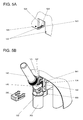
- FIG. 5A shows the FIG. 5A a three-dimensional detail view of a holding place 121, of which the brackets from the preceding FIGS. 1 to 4 preferably have several.
- Each stopping place 121 is essentially formed by a U-shaped, downwardly open recess on the holder. Through the recess two side walls 523, 524 are formed. The side walls 523, 524 each have a retaining groove 122. At least one of the mounting grooves 122 has Snap-525. That in the FIG. 5A only partially visible latching element 525 is a ball catch in a known configuration. This has essentially a ball and a not visible here, because behind the ball arranged compression spring, which are arranged in a blind bore.
- FIG. 5B shows a three-dimensional detail view of the Figures 3 and 4 wherein a dosing unit 140 inserted into the receiving device 104 is shown. This is located in the metering position and consequently over the target vessel 132. Furthermore, it can be seen that the drive device 103 is coupled to the metering unit 140 via the drive shaft 107. As a result, can be operated with the drive device 103, a dosing valve not shown dosing unit 140.
- a guide rail 142 is formed on the dosing unit 140.
- the guide rail 142 further has a trough 541, in which in inserted into the holding station 121 metering unit 140 in the FIG. 5A engages described latch member 525 engages. This is necessary because the dosing unit 140 or functional unit 440, 441 must be released from the receiving device 104 when it is inserted into the holding station 121 and this requires a certain resistance due to the friction conditions.
- the latching element 525 secures the metering unit 140 from falling out of the holding station 121 in an uncontrolled manner.
- the FIG. 5B further shows a windscreen cover 560 fixed to the pickup 104.
- a portion of the metering device 140 protrudes through an opening formed on the windshield cover 560, wherein the contour of the opening of the contour of this part is adapted such that the opening is almost completed when inserted into the receiving device 104 metering unit 140.
- the windshield cover 560 lies in the metering position of the metering device on the windshield 203.
- the metering device may be equipped with a suitable sensor which sends a signal to the control of the changing device when the windshield 203 and the windshield cover 560 touch ,
- the metering device according to the invention may be useful to equip the holding station 121 or the holder, by means of a in FIG. 5B only partially shown feed device to perform.
- at least one gripper coupling point 542 is formed on the dosing unit 140 or functional unit 440, 441.
- the charging device for example an industrial robot, has a gripper 550, which can engage in the gripper coupling point 542, so that the metering unit 140 or functional unit 440, 441 can be frictionally and / or positively connected to the charging device.
- the loading device is arranged independently of the metering device.
- the holding station 121 It makes sense to equip the holding station 121 with a dosing unit 140 or functional unit 440, 441 by means of a horizontal frame directed towards the horizontal movement, since no components of the dosing hinder this direction.
- the holding space 121 or the retaining grooves 122 must be designed such that a charge from this direction, so to speak "from the front” is possible.
- FIG. 6 shows a metering unit 140 inserted into the holding space 121 of a holder, in the plan view according to FIG FIG. 1 specified level AA.
- the holding station 121 and the receiving device it makes sense that the carriers 105 of the receiving device can reach into the holding station 121.
- the dosing unit 140 or functional unit is arranged between a vertically arranged inner plane pair Y, Y 'and an outer plane pair X, X'.
- two superposed support points 143 and a gripper coupling point 542 are arranged.
- Each plane of the outer pair of planes X, X 'each has a guide rail 142. Accordingly, the receiving device and the holding stations 121 are configured, wherein the Garrungsnuten 122 are each arranged in a plane of the outer pair of planes X, X '. In each plane of the inner pair of planes Y, Y 'each two superimposed carrier 105 of the receiving device are arranged. Furthermore, the gripper 550 is adapted to the arranged in the inner plane gripper cup 542. In modification to FIG. 5B is the windscreen cover 660 in FIG. 6 not with the Receiving device, but coupled to the dosing unit 140. Of course, instead of the housing 102, the windshield 203 may also be arranged on the windshield cover 560 of the receiving device 104 or on the windshield cover 660 of the metering unit 140.
Landscapes
- Physics & Mathematics (AREA)
- General Physics & Mathematics (AREA)
- Fluid Mechanics (AREA)
- Basic Packing Technique (AREA)
- Medical Preparation Storing Or Oral Administration Devices (AREA)
- Feeding, Discharge, Calcimining, Fusing, And Gas-Generation Devices (AREA)
- Weight Measurement For Supplying Or Discharging Of Specified Amounts Of Material (AREA)
- Loading And Unloading Of Fuel Tanks Or Ships (AREA)
Abstract
Description
Die vorliegende Erfindung bezieht sich auf eine Dosiervorrichtung mit einer Wechselvorrichtung für Dosiereinheiten oder Funktionseinheiten.The present invention relates to a metering device with a change device for metering units or functional units.
Dosiervorrichtungen für pulver- oder pastenförmiges Dosiergut finden insbesondere beim Dosieren kleiner Mengen mit hoher Präzision in kleine Zielgefässe Verwendung. Häufig sind solche Zielgefässe auf einer Waage platziert, um die Menge des aus der Dosiervorrichtung ausgetragenen Dosierguts zu verwiegen, so dass dieses anschliessend bestimmungsgemäss weiter verarbeitet werden kann. Das Dosiergut befindet sich beispielsweise in einer Dosiereinheit, welche im Wesentlichen ein Entnahmegefäss und einen Dosierkopf aufweist. Im Dosierkopf ist ein Dosierorgan, beispielsweise ein Schieber angeordnet, welcher eine Auslassöffnung freigibt, sobald er betätigt wird. Durch die mit dem Entnahmegefäss verbundene Auslassöffnung kann das Dosiergut hernach in ein unterhalb der Auslassöffnung angeordnetes Zielgefäss fliessen. Der Schieber ist vorzugsweise mit einer von der Dosiereinheit getrennten Antriebsvorrichtung koppelbar.Dosing devices for powdered or paste-like dosage material are used in particular for dosing small quantities with high precision in small target vessels use. Frequently, such target vessels are placed on a balance in order to weigh the amount of metered product discharged from the metering device, so that this can subsequently be further processed as intended. The dosing material is located, for example, in a dosing unit, which essentially has a removal vessel and a dosing head. In the dosing a metering device, such as a slider is arranged, which releases an outlet opening, as soon as it is actuated. By means of the outlet opening connected to the removal vessel, the dosage material can subsequently flow into a target vessel arranged below the outlet opening. The slider is preferably coupled to a separate from the metering drive device.
Häufig werden Dosiervorrichtungen der vorgenannten Art auch zum Herstellen von Mischungen aus mehreren Einzelsubstanzen verwendet. Vorzugsweise ist deshalb eine Wechselvorrichtung vorhanden, mittels welcher die einzelnen Dosiereinheiten mit den Einzelsubstanzen automatisiert in die Dosiervorrichtung eingesetzt, beziehungsweise aus dieser entfernt werden können.Often dosing devices of the aforementioned type are also used for producing mixtures of several individual substances. Preferably, therefore, a changing device is present, by means of which the individual metering units can be used with the individual substances automatically in the metering device, or can be removed from this.
In der
Diesen Nachteilen tragen zwei Ausführungen einer Dosiervorrichtung mit einer Wechselvorrichtung teilweise Rechnung, welche in der
Die vorangehend beschriebenen Ausführungen einer Dosiervorrichtung mit einer Wechselvorrichtung sind einfach herstellbar, haben einen kleinen Flächenbedarf und können dank der Integration der Wechselvorrichtung ohne grossen Installationsaufwand in Betrieb genommen werden.The above-described embodiments of a metering device with a changing device are easy to manufacture, have a small footprint and can be put into operation thanks to the integration of the changing device without much installation effort.
Um eine Kontamination der Umgebung beziehungsweise der Substanz zu vermeiden, sollte jedoch der Abstand der Auslassöffnung einer Dosiereinheit zur Einfüllöffnung eines auf der Waagschale der Wägezelle befindlichen Zielgefässes möglichst klein sein. Dies ist insbesondere bei der Handhabung von toxischen oder hoch reaktiven Substanzen von hoher Wichtigkeit. Vorzugsweise ragt während des Dosiervorganges sogar ein Teil der Dosiereinheit mit deren am unteren Ende angeordneten Auslassöffnung in die Einfüllöffnung hinein, so dass der Innenrandbereich des Zielgefässes nicht mit Dosiergut beschmutzt ist. Dies ist mit den in der
Die Aufgabe der vorliegenden Erfindung besteht darin, eine Dosiervorrichtung zu schaffen, deren Flächenbedarf, beziehungsweise deren freizuhaltender Raum gering ist und bei welcher ein rascher Wechsel und ein rasches Bestücken von Dosiereinheiten beziehungsweise Funktionseinheiten möglich ist.The object of the present invention is to provide a metering device whose area requirement, or whose space to be kept free is small and in which a rapid change and rapid loading of metering units or functional units is possible.
Diese Aufgabe wird mit einer Dosiervorrichtung mit einer Wechselvorrichtung gelöst, welche die im unabhängigen Patentanspruch angegebenen Merkmale aufweist.This object is achieved with a metering device with a changing device, which has the features specified in the independent claim.
Eine Dosiervorrichtung weist einen Grundrahmen, mindestens eine Aufnahmevorrichtung zur Aufnahme einer beliebigen, in die Aufnahmevorrichtung einsetzbaren Dosiereinheit oder Funktionseinheit und mindestens eine Antriebsvorrichtung auf. Wenn eine Dosiereinheit oder Funktionseinheit in die Aufnahmevorrichtung eingesetzt ist, kann diese mit der Antriebsvorrichtung gekoppelt werden. Bezogen auf die Betriebsstellung der Dosiervorrichtung, ist in einer oberen horizontalen Ebene des Grundrahmens eine Halterung angeordnet und mit demselben verbunden. Die Halterung weist mindestens einen Halteplatz für eine Dosiereinheit oder Funktionseinheit auf. In einer unteren horizontalen Ebene des Grundrahmens ist ferner eine Wägezelle angeordnet, welche einen Lastaufnehmer zur Aufnahme eines Zielgefässes aufweist.A dosing device has a base frame, at least one receiving device for receiving any dosing unit or functional unit that can be inserted into the receiving device, and at least one drive device. If a dosing unit or functional unit is inserted into the receiving device, this can be coupled to the drive device. Relative to the operating position of the metering device, a holder is arranged in an upper horizontal plane of the base frame and connected to the same. The holder has at least one holding station for a dosing unit or functional unit. In a lower horizontal plane of the base frame, a load cell is further arranged, which has a load receptor for receiving a target vessel.
Erfindungsgemäss beinhaltet die Dosiervorrichtung eine Wechselvorrichtung, mittels welcher die Aufnahmevorrichtung relativ zum Grundrahmen horizontal verschiebbar ist. Durch die horizontale Verschiebung kann mittels der Aufnahmevorrichtung eine Dosiereinheit oder Funktionseinheit aus dem Halteplatz entfernt und in die Aufnahmevorrichtung aufgenommen, beziehungsweise aus der Aufnahmevorrichtung entfernt und in den Halteplatz aufgenommen werden. Des Weiteren ist mittels der Wechselvorrichtung die Aufnahmevorrichtung zusammen mit der Antriebsvorrichtung relativ zum Grundrahmen vertikal zur Einfüllöffnung eines auf dem Lastaufnehmer aufgelegten Zielgefässes hin, beziehungsweise von der Einfüllöffnung des Zielgefässes zum Halteplatz hin, verschiebbar.According to the invention, the metering device includes a changing device, by means of which the receiving device is horizontally displaceable relative to the base frame. As a result of the horizontal displacement, a dosing unit or functional unit can be removed from the holding station by means of the receiving device and accommodated in the receiving device, or removed from the receiving device and accommodated in the holding station. Furthermore, by means of the changing device, the receiving device together with the drive device relative to the base frame, vertically to the filling opening of a target vessel placed on the load receiver, or displaceable from the filling opening of the target vessel to the holding station.
Der Aufbau und die Funktion einer Dosiereinheit wurden bei der vorangehenden Würdigung des Standes der Technik bereits erklärt und beschrieben. Selbstverständlich können an Stelle einer oder mehrerer Dosiereinheiten auch Funktionseinheiten mit verschiedenen Funktionen verwendet werden. Das Konzept solcher, in eine Dosiervorrichtung einsetzbarer Funktionseinheiten ist im Detail in der europäischen Patentanmeldung
Die Wechselvorrichtung weist somit mindestens eine horizontale Linearführung als Verbindungselement zwischen der Aufnahmevorrichtung und der Antriebsvorrichtung und eine vertikale Linearführung zwischen der Einheit aus Antriebsvorrichtung und Aufnahmevorrichtung und dem Grundrahmen auf. Dazu gehören ferner zu jeder Linearführung eine Antriebseinheit und zum Steuern der Antriebseinheiten eine Steuerung. Wie vorangehend beschrieben, dienen die horizontalen Bewegungen primär dem Übergabevorgang der Dosiereinheit oder Funktionseinheit zwischen der Aufnahmevorrichtung und dem Halteplatz. Dies schliesst aber nicht aus, dass die horizontale Bewegung auch für untergeordnete Bedürfnisse, beispielsweise der Ausrichtung der Dosiereinheit oder Funktionseinheit zum Zielgefäss dienen kann. Die vertikalen Bewegungen dienen primär dem Transport der Dosiereinheit oder Funktionseinheit vom Halteplatz zum Zielgefäss und wieder zurück. Dies schliesst wie bereits zur horizontalen Bewegung erläutert, auch nicht aus, dass vertikale Bewegungen für weitere Bedürfnisse, beispielsweise kurzhubige Entriegelungs-, beziehungsweise Verriegelungsbewegungen verwendet werden können.The changing device thus has at least one horizontal linear guide as a connecting element between the receiving device and the drive device and a vertical linear guide between the unit of drive device and receiving device and the base frame. These also include a drive unit for each linear guide and a controller for controlling the drive units. As described above, the horizontal movements primarily serve the transfer operation of the dosing unit or functional unit between the receiving device and the holding station. However, this does not rule out that the horizontal movement can also serve for subordinate needs, for example the orientation of the dosing unit or functional unit to the target vessel. The vertical movements primarily serve to transport the dosing unit or functional unit from the holding station to the target vessel and back again. This precludes, as already explained for horizontal movement, not even that vertical movements for other needs, such as short-stroke unlocking, or locking movements can be used.
Vorzugsweise weist die Halterung mindestens zwei Halteplätze auf und ist relativ zum Grundrahmen linear verschiebbar oder drehbar ausgebildet. Idealerweise ist die Position jedes Halteplatzes in einer elektronischen Speichereinheit der Dosiervorrichtung eingespeichert, so dass ein in einem Prozessormodul der Dosiervorrichtung ausführbares Betriebsprogramm den gewünschten Halteplatz findet und zu einer weiter unten beschriebenen Übergabestelle drehen kann. In dieser Speichereinheit können selbstverständlich auch Daten der im Halteplatz eingesetzten Dosiereinheit eingespeichert sein. Sofern im Bereich der Halterung eine elektronische Lesevorrichtung, beispielsweise ein RFID- Reader angeordnet ist und die Dosiereinheit ein Identifizierungsmerkmal, beispielsweise einen RFID- Tag aufweist, kann die Erfassung der Daten jeder Dosiereinheit oder Funktionseinheit auch automatisch beim Bestücken der Halterung mit Dosiereinheiten erfolgen. Solche Daten können die technischen Daten der Dosiereinheit, wie beispielsweise das Inbetriebnahmedatum, die Anzahl Dosierungen, das Datum der letzten Dosierung und dergleichen mehr sein. Weitere Daten können die in der Dosiereinheit verfüllte Substanz betreffen, beispielsweise deren Art und Zusammensetzung, deren Verfalldatum, deren ermittelte, die Fliessfähigkeit der Substanz betreffenden Parameter und dergleichen mehr. Auch die Funktionseinheiten können einen RFID-Speicherchip aufweisen, auf welchem technische Daten zur Funktion gespeichert sind. Gegebenenfalls sind sogar Benutzungshinweise oder sogar Programmmodule aus diesem Speicherchip abrufbar, welche einzelne Prozessschritte der Dosiervorrichtung beeinflussen und/oder steuern. Insbesondere bei der Datenerfassung und bei der Bestückung ist die unabhängig bewegbare Halterung von grossem Vorteil. So kann auch während eines Dosiervorganges die Halterung aus nur einer Richtung bestückt werden und es ist nur eine Schreib-Lesevorrichtung notwendig, um die Daten aller RFID- Speicherchips zu erfassen. Ferner kann, sobald die Aufnahmevorrichtung die obere Ebene verlassen hat, jede in der Halterung befindliche Dosiereinheit oder Funktionseinheit jederzeit an der Schreib-Lesevorrichtung vorbeigeführt und deren Daten gelesen oder verändert werden.Preferably, the holder has at least two holding positions and is designed to be linearly displaceable or rotatable relative to the base frame. Ideally, the position of each stopping place is stored in an electronic storage unit of the metering device, so that an operating program executable in a processor module of the metering device finds the desired stopping position and can rotate to a transfer point described below. Of course, data of the dosing unit used in the holding station can also be stored in this memory unit. If an electronic reading device, for example an RFID reader, is arranged in the region of the holder and the dosing unit has an identification feature, for example an RFID tag, the acquisition of the data of each dosing unit or functional unit can also take place automatically when the holder is fitted with dosing units. Such data may be the technical data of the dosing unit, such as the start-up date, the number of doses, the date of the last dose and the like. Further data may relate to the substance filled in the dosing unit, for example its type and composition, its expiry date, its determined parameters relating to the fluidity of the substance and the like. The functional units may also have an RFID memory chip on which technical data for the function are stored. If necessary, even usage instructions or even program modules can be retrieved from this memory chip, which influence and / or control individual process steps of the dosing device. Particularly in the case of data acquisition and assembly, the independently movable mounting is of great advantage. Thus, even during a dosing process, the holder can be equipped from only one direction and it is only a read-write device necessary to capture the data of all RFID memory chips. Furthermore, as soon as the receiving device has left the upper level, each dosing unit or functional unit located in the holder can be guided past the read / write device at any time and its data can be read or changed.
Vorzugsweise weist der mindestens eine Halteplatz mindestens zwei Halterungsnuten und die Aufnahmevorrichtung mindestens zwei Träger auf. Ferner sind an der Dosiereinheit oder Funktionseinheit zu den Trägern passende Auflagestellen und zu den Halterungsnuten passende Führungsschienen ausgebildet. Die Halterungsnuten, Auflagestellen, Träger und Führungsschienen erstrecken sich in ihrer Längsrichtung vorzugsweise parallel zueinander sowie parallel zur horizontalen Bewegung der Wechselvorrichtung.Preferably, the at least one holding place has at least two holding grooves and the receiving device has at least two bearers. Furthermore, suitable support points and guide rails which are suitable for the support grooves are formed on the dosing unit or functional unit with the supports. The retaining grooves, Support points, support and guide rails extend in their longitudinal direction preferably parallel to each other and parallel to the horizontal movement of the changing device.
Um eine ausserordentlich kompakte Bauweise der Dosiereinheit, der Funktionseinheit, des Halteplatzes und der Aufnahmevorrichtung zu ermöglichen, greifen die Träger der Aufnahmevorrichtung vorzugsweise in den Halteplatz hinein. Dies ist dann möglich, wenn die Dosiereinheit oder Funktionseinheit zwischen einem vertikal angeordneten inneren und äusseren Ebenenpaar angeordnet ist, wobei jede Ebene des inneren Ebenenpaars je mindestens eine Auflagestelle und jede Ebene des äusseren Ebenenpaars je mindestens eine Führungsschiene aufweist.In order to enable an exceptionally compact design of the dosing unit, the functional unit, the holding station and the receiving device, the carriers of the receiving device preferably engage in the holding station. This is possible if the dosing unit or functional unit is arranged between a vertically arranged inner and outer plane pair, wherein each plane of the inner plane pair has at least one support point and each plane of the outer pair of planes at least one guide rail.
Die Bestückung des mindestens einen Halteplatzes mit einer Dosiereinheit oder Funktionseinheit kann manuell erfolgen. Sofern aber die erfindungsgemässe Dosiervorrichtung beispielsweise in einer grösseren Anlage integriert ist, kann es sinnvoll sein, die Bestückung des Halteplatzes beziehungsweise der Halterung, mittels einer Beschickungsvorrichtung durchzuführen. Zu diesem Zwecke ist an der Dosiereinheit oder Funktionseinheit mindestens eine Greiferkuppelstelle ausgebildet. Die Beschickungsvorrichtung, beispielsweise ein Industrieroboter, weist einen Greifer auf, welcher in die Greiferkuppelstelle eingreifen kann, so dass die Dosiereinheit oder Funktionseinheit kraftschlüssig und/oder formschlüssig mit der Beschickungsvorrichtung verbindbar ist. Um die Übertragung von Erschütterungen zu vermeiden, ist die Beschickungsvorrichtung vorzugsweise unabhängig zur Dosiervorrichtung angeordnet. Sinnvollerweise erfolgt die Bestückung des Halteplatzes mit einer Dosiereinheit oder Funktionseinheit mittels einer zum Grundrahmen hin gerichteten, horizontalen Bewegung, da keinerlei Bauteile der Dosiervorrichtung diese Richtung behindern. Selbstverständlich müssen der Halteplatz beziehungsweise die Halterungsnuten dahingehend ausgebildet sein, dass eine Beschickung aus dieser Richtung, sozusagen "von Vorne" möglich ist. Idealerweise wird die Dosiereinheit oder Funktionseinheit auch von der Wechselvorrichtung aus dieser Richtung in den mindestens einen Halteplatz eingeführt, um die Dosiereinheit oder Funktionseinheit von der Aufnahmevorrichtung zu entfernen. Die Aufnahme der Dosiervorrichtung in die Aufnahmevorrichtung erfolgt dementsprechend in einer vom Grundrahmen weg gerichteten, horizontalen Bewegung. Insbesondere bei der Bestückung ist die unabhängig von der Aufnahmevorrichtung bewegbare Halterung von grossem Vorteil. So kann während des Dosierens die Halterung aus nur einer Richtung bestückt werden.The equipping of the at least one holding place with a dosing unit or functional unit can be done manually. If, however, the metering device according to the invention is integrated, for example, in a larger system, it can be useful to carry out the loading of the holding station or the holder by means of a loading device. For this purpose, at least one gripper coupling point is formed on the dosing unit or functional unit. The charging device, for example an industrial robot, has a gripper which can engage in the gripper coupling point, so that the metering unit or functional unit can be positively and / or positively connected to the charging device. In order to avoid the transmission of vibrations, the charging device is preferably arranged independently of the metering device. It makes sense to equip the holding station with a dosing unit or functional unit by means of a directed towards the base frame, horizontal movement, since no components of the dosing hinder this direction. Of course, the holding space or the retaining grooves must be designed to the effect that a feed from this direction, so to speak "from the front" is possible. Ideally, the dosing unit or functional unit is also introduced by the changing device from this direction into the at least one holding station in order to remove the dosing unit or functional unit from the receiving device. The recording of the metering device in the receiving device is accordingly in a direction away from the base frame, horizontal movement. Especially at the Assembly is the independent of the receiving device movable mount of great advantage. Thus, during dosing, the holder can be equipped from one direction only.
Damit die Dosiereinheit oder Funktionseinheit während den Bewegungsvorgängen nicht aus der Aufnahmevorrichtung oder infolge von Erschütterungen nicht aus dem Halteplatz fällt, kann zwischen mindestens einer Halterungsnut und einer Führungsschiene und/oder zwischen mindestens einem Träger und einer Auflagestelle ein durch Krafteinwirkung lösbares Einrastelement angeordnet sein. Solche Einrastelemente können federbeaufschlagte Kugelrastelemente, Federzungen und dergleichen mehr, oder sogar Magnetpaare sein.So that the dosing unit or functional unit does not fall out of the holding position during the movement processes out of the receiving device or as a result of vibrations, a force-releasable latching element can be arranged between at least one holding groove and a guide rail and / or between at least one carrier and a support point. Such latching elements may be spring-loaded ball detents, spring tongues and the like more, or even magnetic pairs.
An Stelle der Einrastelemente kann die mindestens eine Halterungsnut und/oder Auflagestelle eine, orthogonal zu ihrer Längsachse und sich im Wesentlichen in vertikaler Richtung erstreckende Ausnehmung aufweisen und an der mindestens einen Führungsschiene und/oder am Träger ein, orthogonal zu seiner Längsachse und sich im Wesentlichen in vertikaler Richtung erstreckender Vorsprung ausgebildet sein. Zum Trennen der Dosiervorrichtung von der Aufnahmevorrichtung und/oder vom mindestens einen Halteplatz ist dann eine vertikale Entriegelungsbewegung notwendig. Entsprechend ist zum Einsetzen der Dosiereinheit oder Funktionseinheit in die Aufnahmevorrichtung und/oder in den mindestens einen Halteplatz eine vertikale Absetzbewegung erforderlich.Instead of the latching elements, the at least one support groove and / or support point may have a recess extending orthogonally to its longitudinal axis and substantially in the vertical direction and at the at least one guide rail and / or on the support, orthogonal to its longitudinal axis and substantially be formed in the vertical direction extending projection. To disconnect the metering device from the receiving device and / or from the at least one stopping place then a vertical unlocking movement is necessary. Accordingly, a vertical settling movement is required for inserting the dosing unit or functional unit into the receiving device and / or in the at least one holding station.
Je nach Einsatzgebiet, beispielsweise in Entwicklungslabors für pharmazeutische Substanzen, müssen Kleinstmengen dieser Substanzen hochpräzise ausdosiert werden können. Dosiervorrichtungen, welche diese Anforderungen erfüllen, weisen eine hochpräzise Wägezelle auf. Mit deren Wägesignal wird der Dosiervorgang überwacht und gesteuert. Der Dosier- und Messvorgang findet innerhalb eines Windschutzes statt, so dass Luftturbulenzen der Umgebung das Wägeresultat nicht beeinflussen. Um komplizierte Windschutzkonstruktionen mit mechanisch anspruchsvollen Schleusen zu vermeiden, müssten die in der
Die vorliegende erfindungsgemässe Dosiervorrichtung mit einer Wechselvorrichtung ermöglicht nun den Einsatz eines den Lastaufnehmer umgebenden und mit dem Grundrahmen verbundenen Windschutzes. Dieser kann auf die zum Einsatz gelangenden Zielgefässe abgestimmt sein. Dementsprechend kann sein Innenvolumen sehr klein gehalten werden. Da der Transfer der Dosiereinheit oder Funktionseinheit von der Halterung zum Zielgefäss im Wesentlichen in vertikaler Richtung erfolgt, ist vorzugsweise der Windschutz in Richtung der oberen horizontalen Ebene und demzufolge gegen oben zumindest partiell offen.The present inventive metering device with a changing device now allows the use of a windscreen surrounding the load receptor and connected to the base frame. This can be adapted to the target vessels used. Accordingly, its internal volume can be kept very small. Since the transfer of the dosing unit or functional unit from the holder to the target vessel takes place essentially in the vertical direction, the draft shield is preferably at least partially open in the direction of the upper horizontal plane and consequently upwards.
Um während eines Dosiervorgangs den Windschutz auch gegen oben abzuschliessen, kann an der Aufnahmevorrichtung eine geeignete Windschutzabdeckung in einer ersten Ausführung angeordnet sein. Diese Windschutzabdeckung ist mit mindestens einem Durchbruch für einen an der Dosiereinheit oder Funktionseinheit ausgebildeten Auslass versehen. Anstelle des Auslasses kann bei einer Funktionseinheit, wie weiter oben beschrieben, selbstverständlich auch deren Werkzeug, beispielsweise ein Temperaturfühler oder ein Rührwerk durch den Durchbruch hindurchreichen.In order to close the windbreak against the top during a metering operation, a suitable windscreen cover may be arranged in a first embodiment on the receiving device. This windscreen cover is provided with at least one opening for an outlet formed on the dosing unit or functional unit. Instead of the outlet, of course, its tool, for example a temperature sensor or an agitator, can also pass through the opening in the case of a functional unit, as described above.
In einer zweiten Ausführung kann die Windschutzabdeckung auch an der Dosiereinheit oder Funktionseinheit angeordnet sein. Auch mittels dieser ist der nach oben offene Windschutz verschliessbar. Selbstverständlich kann auch der gesamte Windschutz am Dosierkopf ausgebildet sein und beim Dosiervorgang das Zielgefäss und den Lastaufnehmer vollständig abdecken.In a second embodiment, the windshield cover can also be arranged on the dosing unit or functional unit. Also by means of this open top windshield is closed. Of course, the entire windscreen can be formed on the dosing and completely cover the target vessel and the loader during dosing.
Sofern der mit der Auslassöffnung versehene Bereich der Dosiereinheit teilweise in das Zielgefäss hineinragen soll, muss eine genügend grosse Öffnung in der Windschutzabdeckung vorhanden sein. Vorzugsweise ist die Kontur der Öffnung des partiell nach oben offenen Windschutzes auf denjenigen Querschnitt der Dosiereinheit angepasst, welcher während eines Dosiervorgangs in dieser Öffnung angeordnet ist.If the region of the dosing unit provided with the outlet opening is intended to protrude partially into the target vessel, a sufficiently large opening must be present in the windscreen cover. Preferably, the contour of the opening of the partially upwardly open draft shield is adapted to that cross section of the dosing unit, which is arranged during a dosing in this opening.
Dadurch wird ein Luftaustausch zwischen dem Windschutz-Innenraum und der Umgebung weitgehend verhindert.As a result, an air exchange between the windscreen interior and the environment is largely prevented.
Beim Dosieren klebriger Substanzen kann es möglich sein, dass im Bereich der Auslassöffnung der Dosiereinheit einzelne Partikel an deren Gehäuse- Aussenseite hängen bleiben. Insbesondere sind aber auch die Funktionseinheiten nach deren Gebrauch kontaminiert. Vorzugsweise ist deshalb am Grundrahmen eine Reinigungsvorrichtung zur Reinigung der Dosiereinheiten und Funktionseinheiten angeordnet. Je nach Ausführung der Dosiervorrichtung kann diese bei der Halterung oder auch in einer Zwischenposition angeordnet sein. Die Anordnung im Bereich der Halterung hat den Vorteil, dass mittels einer Verschiebung oder Rotation der Halterung relativ zum Grundrahmen der Halteplatz in den Bereich der Reinigungsvorrichtung gelangen kann. Um mit der Aufnahmevorrichtung eine in einer Zwischenposition angeordnete Reinigungsvorrichtung anzufahren, sind gegebenenfalls wie oben bereits erwähnt, weitere untergeordnete Bewegungen in horizontaler und vertikaler Richtung erforderlich. Eine Reinigungsvorrichtung kann eine Abstreifvorrichtung und/oder eine Absaugvorrichtung und/oder eine Waschstation sein.When dosing sticky substances, it may be possible for individual particles to stick to the exterior of the housing in the region of the outlet opening of the dosing unit. In particular, however, the functional units are contaminated after their use. Preferably, therefore, a cleaning device for cleaning the dosing units and functional units is arranged on the base frame. Depending on the design of the metering device, this can be arranged in the holder or in an intermediate position. The arrangement in the region of the holder has the advantage that by means of a displacement or rotation of the holder relative to the base frame, the holding position can reach the region of the cleaning device. In order to approach the receiving device arranged in an intermediate position cleaning device, if necessary, as mentioned above, further subordinate movements in the horizontal and vertical directions are required. A cleaning device may be a stripping device and / or a suction device and / or a washing station.
Selbstverständlich kann die Halterung nicht nur eine, sondern mehrere in einer horizontalen Ebene und linear nebeneinander angeordnete Halteplätze für Dosiereinheiten und Funktionseinheiten aufweisen. Jeder Halteplatz ist relativ zum Grundrahmen und zu einer definierten, zum Grundrahmen ortsfesten Übergabestelle linear horizontal verschiebbar angeordnet ist. Die Wechselvorrichtung ist derart ausgelegt, dass die Aufnahmevorrichtung die jeweilige Dosiereinheit oder Funktionseinheit an dieser Übergabestelle von ihrem Halteplatz aufnimmt beziehungsweise an diesen abgibt.Of course, the holder may have not only one, but a plurality of in a horizontal plane and linearly juxtaposed holding stations for dosing units and functional units. Each stop is relative to the base frame and a defined, fixed to the base frame transfer point is arranged linearly horizontally displaceable. The changing device is designed in such a way that the receiving device receives the respective dosing unit or functional unit at this transfer point from its holding station or discharges it to it.
Wenn sehr viele Dosiereinheiten und Funktionseinheiten in der Halterung untergebracht werden sollen, kann es sinnvoll sein, dass die Halterung mehrere in einer horizontalen Ebene und ringförmig nebeneinander angeordnete Halteplätze für Dosiereinheiten aufweist. Diese Halterung ist um eine vertikale Drehachse relativ zum Grundrahmen drehbar. Dadurch kann jeder Halteplatz zu einer definierten, zum Grundrahmen fixen Übergabestelle bewegt werden.If a large number of dosing units and functional units are to be accommodated in the holder, it may be useful for the holder to have a plurality of holding stations for dosing units arranged in a horizontal plane and annularly next to one another. This holder is rotatable about a vertical axis of rotation relative to the base frame. As a result, each stop can be moved to a defined, fixed to the base frame transfer point.
Es versteht sich von selbst, dass zwischen der oberen Ebene des Grundrahmens, in welcher die Halterung angeordnet ist und der unteren Ebene des Grundrahmens, in welcher die Wägezelle mit dem Lastaufnehmer angeordnet ist, mindestens eine Zwischenhalterung in mindestens einer horizontalen Zwischenebene angeordnet sein kann. Damit Dosiereinheiten oder Funktionseinheiten aus der oberen Ebene in die untere Ebene befördert werden können, sollte an der mindestens einen Zwischenhalterung eine Durchgangsposition für die Aufnahmevorrichtung ausgebildet sein. Diese Durchgangsposition kann deshalb keinen Halteplatz aufweisen.It goes without saying that between the upper level of the base frame, in which the holder is arranged and the lower level of the base frame, in which the load cell is arranged with the load receiver, at least one intermediate holder can be arranged in at least one horizontal intermediate plane. So that dosing units or functional units can be conveyed from the upper level into the lower level, a passage position for the receiving device should be formed on the at least one intermediate holder. This passage position can therefore have no stopping place.
In der mindestens einen Dosiereinheit kann eine pulverförmige, pastenförmige oder flüssige Substanz verfüllt sein. Ferner kann die Dosiereinheit aber auch eine Versorgungsleitung aufweisen, welche mit einem Vorratsgefäss und gegebenenfalls mit einer Pumpe verbunden ist.In the at least one metering unit, a powdery, pasty or liquid substance can be filled. Furthermore, however, the dosing unit can also have a supply line, which is connected to a storage vessel and optionally to a pump.
Ferner kann eine Vielzahl von unterschiedlichen Funktionseinheiten eingesetzt werden. Beispielsweise kann eine Funktionseinheit eine Titratoreinheit, eine Pumpeinheit, eine Pipettiereinheit, eine Einheit mit Rohrleitungen und Armaturen, eine Behältereinheit eine Sensoreinheit oder ein Adapter zur Aufnahme einer dieser Einheiten oder weiterer Einheiten sein. Als weitere Einheiten können beispielsweise auch Rührwerke, Mahlwerke oder Heiz- und/oder Kühleinheiten als Funktionseinheiten eingesetzt werden. Dadurch, dass aus einer ganzen Palette verschiedener einsetzbarer Funktionseinheiten ausgewählt werden kann, ist die Dosiervorrichtung nicht nur zum dosieren von pulver- oder pastenförmigem Dosiergut sowie von Flüssigkeiten verwendbar, sondern kann zur Weiterbehandlung des Dosiergutes in eine Art Minilabor mit über die Kraftmessvorrichtung kontinuierlich erfassbaren Gewichtswerten verwandelt werden.Furthermore, a plurality of different functional units can be used. For example, a functional unit may be a titrator unit, a pumping unit, a pipetting unit, a unit with pipelines and fittings, a container unit, a sensor unit or an adapter for accommodating one of these units or further units. As further units, for example, agitators, grinders or heating and / or cooling units can be used as functional units. Characterized in that it can be selected from a whole range of different usable functional units, the metering device is not only for metering of powdered or pasty Dosiergut and liquids used, but can be further processed for further processing of the dosage in a kind of mini lab with the force measuring device continuously detectable weight values become.
Einzelheiten der erfindungsgemässen Dosiervorrichtung ergeben sich anhand der Beschreibung der in den Zeichnungen dargestellten Ausführungsbeispiele. Es zeigen:
- Figur 1
- eine schematische, dreidimensionale Darstellung einer Dosiervorrichtung mit einer Wechselvorrichtung, mit einem Grundrahmen, mit einer am Grundrahmen drehbar gelagerten, ringförmigen Halterung, mit einer Antriebsvorrichtung und einer Aufnahmevorrichtung, welche durch die Wechselvorrichtung mit dem Grundrahmen verbunden sind und einer am Grundrahmen angeordneten Wägezelle mit einem Lastaufnehmer sowie zwölf in die Halterung einsetzte Dosiereinheiten;
- Figur 2
- die schematische, dreidimensionale Darstellung der Dosiervorrichtung aus der
Figur 1 , wobei der Lastaufnehmer und ein auf den Lastaufnehmer aufgelegtes Zielgefäss mit einem Windschutz umschlossen ist und sich die Aufnahmevorrichtung und die darin eingesetzte Dosiereinheit in einer Zwischenposition zwischen der Halterung und der Wägezelle befindet; - Figur 3
- im Wesentlichen die schematische, dreidimensionale Darstellung der Dosiervorrichtung aus den
Figuren 1 und2 , wobei am Grundrahmen zwischen der Halterung und dem Zielgefäss zusätzlich eine Zwischenhalterung angeordnet ist und sich die Aufnahmevorrichtung und die darin eingesetzte Dosiereinheit unmittelbar über dem Zielgefäss befindet; - Figur 4
- eine schematische, dreidimensionale Darstellung einer Dosiervorrichtung mit einer Wechselvorrichtung, mit einem Grundrahmen, mit einer am Grundrahmen linear verschiebbar geführten Halterung, mit einer Antriebsvorrichtung und einer Aufnahmevorrichtung, welche durch die Wechselvorrichtung mit dem Grundrahmen verbunden sind und einer am Grundrahmen angeordneten Wägezelle mit einem Lastaufnehmer sowie mit drei Dosiereinheiten und zwei Funktionseinheiten, welche in die Halterung einsetzt sind;
- Figur 5A
- eine dreidimensionale Detailansicht eines Halteplatzes der Halterung aus den vorangehenden
Figuren 1 bis 3 ; - Figur 5B
- eine dreidimensionale Detailansicht des sich über dem Zielgefäss befindlichen Dosierkopfs aus den
Figuren 3 und4 , wobei an der Aufnahmevorrichtung zusätzlich eine Windschutzabdeckung angeordnet ist und ferner ein Teil eines Greifers einer Beschickungsvorrichtung angedeutet ist; - Figur 6
- eine Dosiereinheit eingesetzt in den Halteplatz einer Halterung, in der Aufsicht gemäss der in
Figur 1 angegebenen Ebene A-A.
- FIG. 1
- a schematic, three-dimensional representation of a metering device with a changing device, with a base frame, with a rotatably mounted on the base frame, annular support, with a drive device and a receiving device, which by the Changing device are connected to the base frame and arranged on the base frame load cell with a load receptor and twelve inserted into the holder metering units;
- FIG. 2
- the schematic, three-dimensional representation of the metering of the
FIG. 1 wherein the load receiver and a target vessel placed on the load receiver are enclosed with a windscreen and the receiving device and the dosing unit inserted therein are in an intermediate position between the holder and the weighing cell; - FIG. 3
- essentially the schematic, three-dimensional representation of the metering device from the
FIGS. 1 and2 wherein an intermediate support is additionally arranged on the base frame between the holder and the target vessel and the receiving device and the dosing unit inserted therein are located directly above the target vessel; - FIG. 4
- a schematic, three-dimensional representation of a metering device with a changing device, with a base frame, with a linearly displaceably guided on the base frame holder, with a drive device and a receiving device, which are connected by the changing device to the base frame and arranged on the base frame load cell with a load receiver and with three dosing units and two functional units, which are inserted into the holder;
- FIG. 5A
- a three-dimensional detail view of a holding place of the holder from the preceding
FIGS. 1 to 3 ; - FIG. 5B
- a three-dimensional detailed view of the located above the target vessel dosing from the
Figures 3 and4 , wherein additionally arranged on the receiving device, a windshield cover and further a portion of a gripper of a feeder is indicated; - FIG. 6
- a dosing unit used in the holding place of a holder, in the supervision according to the in
FIG. 1 specified level AA.
Die
In einer unteren Ebene des Grundrahmens 101 ist ein Gehäuse 102 ausgebildet, welches im Teilschnitt dargestellt ist, um eine im Innern des Gehäuses 102 angeordnete Wägezelle 130 zu zeigen. Ein Lastaufnehmer 131, welcher in der Betriebsstellung der Dosiervorrichtung 100 oberhalb des Gehäuses 102 angeordnet ist, ist mittels eines durch das Gehäuse 102 geführten Kraftübertragungsgliedes 133 mit der Wägezelle 130 verbunden. Auf dem Lastaufnehmer 131 ist ein Zielgefäss 132 aufgelegt.In a lower level of the
Innerhalb des rohrförmigen Grundrahmens 101 ist teilweise eine vertikale Linearführung 111 der Wechselvorrichtung 110 erkennbar. Mittels dieser vertikalen Linearführung 111 wird eine Antriebsvorrichtung 103 und eine knapp erkennbare Aufnahmevorrichtung 104 vertikal verschiebbar geführt. Die Antriebsvorrichtung 103 ist mit einem in der Dosiereinheit 140 angeordneten, in
Der in der Übergabestelle 123 befindliche Halteplatz 121 ist mit einer Dosiereinheit 140 bestückt. Ferner ist in der
In der
Die Aufnahmevorrichtung 104 ist gabelförmig ausgebildet und weist vier sich in horizontaler Richtung erstreckende Träger 105 mit je einem sich in vertikaler Richtung erstreckenden Vorsprung 106 auf. Bei in die Aufnahmevorrichtung 104 eingesetzter Dosiereinheit 140 greifen die Träger 105 in an der Dosiereinheit 140 ausgebildete Auflagestellen 143 ein. Wegen der eingesetzten Dosiereinheit 140 sind nur zwei Träger 105 sichtbar. Die Vorsprünge 106 greifen in an der Dosiereinheit 140 ausgebildete Ausnehmungen 141 ein und verhindern dadurch, dass die Dosiereinheit 140 während des Transports mittels der Wechselvorrichtung 110 aus der Aufnahmevorrichtung 104 fällt. Zwecks der Aufnahme einer Dosiereinheit 140 in die Aufnahmevorrichtung 104 beziehungsweise deren Entfernung aus der Aufnahmevorrichtung 104 muss deshalb eine vertikale, kurzhubige Bewegung der Aufnahmevorrichtung 104 relativ zur Dosiereinheit 140 erfolgen.The receiving
Die in der
Auch die
In
Nach dem Rührvorgang ist das Rührwerk mit der im Zielgefäss 132 vorhandenen Lösung benetzt und daher kontaminiert. Zum Reinigen der Funktionseinheiten 440, 441 und Dosiereinheiten 140 kann die Dosiervorrichtung 400 eine sehr schematisch dargestellte Reinigungsvorrichtung 450 aufweisen, die am Grundrahmen 401 angeordnet sein kann. Zum Reinigen kann beispielsweise die benutzte Funktionseinheit 440, 441 zuerst wieder an ihren Halteplatz 121 befördert und der Halteplatz 121 anschliessend zur Reinigungsvorrichtung 450 verschoben werden. Es sind aber auch Anordnungen möglich, bei welcher die Reinigungsvorrichtung 450 während des Rückweges einer Dosiereinheit 140 oder Funktionseinheit 440, 441 zu ihrem Halteplatz 121 durchfahren wird. Die Reinigungsvorrichtung 450 kann selbstverständlich verschiedene Zusatzmodule aufweisen, so zum Beispiel eine Absaugvorrichtung für mit Pulver kontaminierte Dosiereinheiten 140 und/oder eine Waschstation für kontaminierte Funktionseinheiten 440, 441. Ferner können weitere Elemente wie Bürsten, Warmluftgebläse zum Trocknen und dergleichen mehr eingesetzt werden.After the stirring process, the stirrer is wetted with the solution present in the
Um Details besser darstellen und beschreiben zu können, zeigt die
Wie bereits in der Beschreibung von
Die
Sofern die erfindungsgemässe Dosiervorrichtung in einer grösseren Anlage integriert ist, kann es sinnvoll sein, die Bestückung des Halteplatzes 121 beziehungsweise der Halterung, mittels einer in
Obwohl die Erfindung durch die Darstellung spezifischer Ausführungsbeispiele beschrieben worden ist, ist es offensichtlich, dass zahlreiche weitere Ausführungsvarianten in Kenntnis der vorliegenden Erfindung geschaffen werden können, beispielsweise indem die Merkmale der einzelnen Ausführungsbeispiele wie beispielsweise die Windschutzabdeckung miteinander kombiniert und/oder einzelne Funktionseinheiten der Ausführungsbeispiele ausgetauscht werden. Insbesondere kann die Anordnung der Träger, der Auflagestellen, der Führungsnuten und der Führungsschienen auf dem inneren und äusseren Ebenenpaar nach dem Belieben des Fachmannes erfolgen. Gegebenenfalls kann dadurch eine Codierung erreicht werden, so dass Funktionseinheiten und Dosiereinheiten in unterschiedliche, jeweils ausschliesslich für sie vorgesehene Stellplätze eingesetzt werden können. Ferner ist auch denkbar, dass mehrere Aufnahmevorrichtungen und mehrere Antriebsvorrichtungen an einer Wechselvorrichtung angeordnet sind. Die Dosiervorrichtung kann auch mehrere unabhängig voneinander betreibbare Wechselvorrichtungen mit je einer Aufnahmevorrichtung und einer Antriebsvorrichtung aufweisen. Dementsprechend werden solche Kombinationen und Alternativen als Teil der Erfindung betrachtet.Although the invention has been described by way of illustrating specific embodiments, it will be apparent that numerous other embodiments can be provided with the knowledge of the present invention by, for example, combining the features of the particular embodiments such as the windshield cover and / or replacing individual functional units of the embodiments become. In particular, the arrangement of the carrier, the support points, the guide and the guide rails on the inner and outer plane pair can be done at the discretion of the skilled person. Optionally, a coding can be achieved thereby, so that functional units and metering units can be used in different parking spaces provided exclusively for them. Furthermore, it is also conceivable that a plurality of receiving devices and a plurality of drive devices are arranged on a changing device. The metering device may also have a plurality of independently operable changing devices each having a receiving device and a drive device. Accordingly, such combinations and alternatives are considered part of the invention.
- 400, 300, 100400, 300, 100
- Dosiervorrichtungmetering
- 401, 101401, 101
- Grundrahmenbase frame
- 102102
- Gehäusecasing
- 103103
- Antriebsvorrichtungdriving device
- 104104
- Aufnahmevorrichtungcradle
- 105105
- Trägercarrier
- 106106
- Vorsprunghead Start
- 107107
- Antriebswelledrive shaft
- 110110
- Wechselvorrichtungchanging device
- 111111
- vertikale Linearführungvertical linear guide
- 112112
- horizontale Linearführunghorizontal linear guide
- 420, 120420, 120
- Halterungbracket
- 321, 121321, 121
- Halteplatzstopping place
- 122122
- Halterungsnutretaining groove
- 123123
- ÜbergabestelleTransfer point
- 130130
- Wägezelleload cell
- 131131
- Lastaufnehmerload sensor
- 132132
- Zielgefässtarget vessel
- 133133
- KraftübertragungsgliedPower transmission member
- 140140
- Dosiereinheitdosing
- 141141
- Ausnehmungrecess
- 142142
- Führungsschieneguide rail
- 143143
- Auflagestellesupport point
- 201201
- erster Pfeilfirst arrow
- 202202
- zweiter Pfeilsecond arrow
- 203203
- Windschutzwindshield
- 320320
- Zwischenhalterungintermediate support
- 322322
- DurchgangspositionPassing position
- 390390
- Auffangschaledrip tray
- 424424
- Längsführunglongitudinal guide
- 441, 440441, 440
- Funktionseinheitfunctional unit
- 442442
- VorratsgefässStorage jar
- 443443
- Versorgungsleitungsupply line
- 450450
- Reinigungsvorrichtungcleaning device
- 524, 523524, 523
- SeitenwandSide wall
- 525525
- Einrastelementlatching
- 541541
- Muldetrough
- 542542
- GreiferkuppelstelleClaw coupling point
- 550550
- Greifergrab
- 660, 560660, 560
- WindschutzabdeckungWindshield cover
Claims (17)
Priority Applications (5)
| Application Number | Priority Date | Filing Date | Title |
|---|---|---|---|
| EP08168761A EP2184590B1 (en) | 2008-11-10 | 2008-11-10 | Dosing device with an exchangeable device for dosing units |
| PCT/EP2009/061987 WO2010052057A1 (en) | 2008-11-10 | 2009-09-16 | Metering device having a changing device for metering units |
| CN200980144875.6A CN102209886B (en) | 2008-11-10 | 2009-09-16 | Metering device having a changing device for metering units |
| JP2011535057A JP5529880B2 (en) | 2008-11-10 | 2009-09-16 | Dose dispensing device with exchange mechanism for dose dispensing unit |
| US13/101,184 US8176950B2 (en) | 2008-11-10 | 2011-05-05 | Dosage-dispensing device with a changing mechanism for dosage-dispensing units |
Applications Claiming Priority (1)
| Application Number | Priority Date | Filing Date | Title |
|---|---|---|---|
| EP08168761A EP2184590B1 (en) | 2008-11-10 | 2008-11-10 | Dosing device with an exchangeable device for dosing units |
Publications (2)
| Publication Number | Publication Date |
|---|---|
| EP2184590A1 true EP2184590A1 (en) | 2010-05-12 |
| EP2184590B1 EP2184590B1 (en) | 2012-08-22 |
Family
ID=40647673
Family Applications (1)
| Application Number | Title | Priority Date | Filing Date |
|---|---|---|---|
| EP08168761A Not-in-force EP2184590B1 (en) | 2008-11-10 | 2008-11-10 | Dosing device with an exchangeable device for dosing units |
Country Status (5)
| Country | Link |
|---|---|
| US (1) | US8176950B2 (en) |
| EP (1) | EP2184590B1 (en) |
| JP (1) | JP5529880B2 (en) |
| CN (1) | CN102209886B (en) |
| WO (1) | WO2010052057A1 (en) |
Cited By (3)
| Publication number | Priority date | Publication date | Assignee | Title |
|---|---|---|---|---|
| WO2014169897A1 (en) * | 2013-04-19 | 2014-10-23 | Glatt Systemtechnik Gmbh | Device for introducing a defined quantity of a second powder into a process vessel |
| US9150119B2 (en) | 2013-03-15 | 2015-10-06 | Aesynt Incorporated | Apparatuses, systems, and methods for anticipating and delivering medications from a central pharmacy to a patient using a track based transport system |
| US9511945B2 (en) | 2012-10-12 | 2016-12-06 | Aesynt Incorporated | Apparatuses, systems, and methods for transporting medications from a central pharmacy to a patient in a healthcare facility |
Families Citing this family (16)
| Publication number | Priority date | Publication date | Assignee | Title |
|---|---|---|---|---|
| USD667961S1 (en) * | 2009-12-02 | 2012-09-25 | Mettler-Toledo Ag | Laboratory instrument |
| IT1403848B1 (en) * | 2011-02-04 | 2013-11-08 | Carpigiani Group Ali Spa | MACHINE FOR THE PRODUCTION AND DISTRIBUTION OF SEMILIQUID AND / OR SEMISOLID FOOD PRODUCTS |
| US8746506B2 (en) | 2011-05-26 | 2014-06-10 | Pepsico, Inc. | Multi-tower modular dispensing system |
| US8985396B2 (en) | 2011-05-26 | 2015-03-24 | Pepsico. Inc. | Modular dispensing system |
| DE102013013549A1 (en) * | 2013-08-13 | 2015-02-19 | Eisenmann Ag | Changing device for coating media and coating system for coating objects |
| BR112016026477A2 (en) * | 2014-05-13 | 2017-08-15 | Smidth As F L | DOSAGE AND CLEANING SAMPLE PREPARATION APPARATUS AND METHODS THEREOF |
| US10893765B2 (en) * | 2015-06-26 | 2021-01-19 | Kitchen Mate Inc. | System and method of an attachable spice dispensing device for an automatic meal preparation apparatus |
| FR3048080B1 (en) * | 2016-02-19 | 2018-03-23 | Didier Santo | PORTABLE DEVICE AND DOSING METHOD, RESERVOIR, SYSTEM COMPRISING SUCH A DEVICE AND TANK |
| US9845167B1 (en) * | 2016-09-01 | 2017-12-19 | Multiply Labs Inc. | Dispensing system |
| EP3327409B1 (en) * | 2016-11-29 | 2019-09-11 | Mettler-Toledo GmbH | Automated dosage-dispensing system for powdery substances, and method of ascertaining that the system is ready for operation |
| US10464030B2 (en) * | 2017-04-03 | 2019-11-05 | L'oreal | System for forming a cosmetic composition |
| FR3072326B1 (en) * | 2017-10-18 | 2019-10-25 | Societe Bic | INK MIXING DEVICE, AN ASSEMBLY COMPRISING THE DEVICE AND A METHOD OF USING THE SAME |
| EP3821215A4 (en) * | 2018-07-09 | 2022-03-30 | Bushnell, Inc. | Dual barrel powder dispenser |
| FR3093712B1 (en) * | 2019-03-11 | 2021-04-09 | Fillon Technologies | liquid or pasty product dispensing machine |
| US11535409B1 (en) * | 2019-12-18 | 2022-12-27 | Richard James DeMartini | Personal liquid cannabis 6D oil printer and smart cartridges |
| CN111572851B (en) * | 2020-06-02 | 2021-10-19 | 祁东农交汇食品有限公司 | Agricultural and sideline products canning machine |
Citations (5)
| Publication number | Priority date | Publication date | Assignee | Title |
|---|---|---|---|---|
| DE19841478A1 (en) * | 1997-09-12 | 1999-03-25 | Rainer Schneckenburger | Controlled feed device for filling viscous, pasty, powder or granulate products |
| EP1930702A1 (en) * | 2006-12-07 | 2008-06-11 | Mettler-Toledo AG | Metering device for metered material in powder or paste form |
| EP1947427A1 (en) | 2007-01-19 | 2008-07-23 | Mettler-Toledo AG | Method for optimising dosage processes and dosage device |
| EP1959243A1 (en) | 2007-02-13 | 2008-08-20 | Mettler-Toledo AG | Metering device with an adapter device for an installable unit |
| EP1959244A1 (en) | 2007-02-13 | 2008-08-20 | Mettler-Toledo AG | Metering device with striking mechanism |
Family Cites Families (24)
| Publication number | Priority date | Publication date | Assignee | Title |
|---|---|---|---|---|
| NL153442B (en) * | 1973-09-28 | 1977-06-15 | Basf Farben & Fasern | TIN MIXING DEVICE. |
| FI58264C (en) * | 1979-05-10 | 1981-01-12 | Winter Oy | MASKIN FOER NYANSERING AV MAOLFAERGER |
| DE3146667C2 (en) * | 1981-11-25 | 1984-12-06 | Werner & Pfleiderer, 7000 Stuttgart | Method and device for mixing and metering several mix components |
| US4628974A (en) * | 1984-03-14 | 1986-12-16 | Meyer Ronald K | Apparatus for automated assembly of flowable materials |
| DE3880376T2 (en) * | 1987-06-08 | 1993-10-21 | Ngk Insulators Ltd | Apparatus for weighing powdery material. |
| US5038839A (en) * | 1988-07-18 | 1991-08-13 | Takeda Chemical Industries, Ltd. | Filling apparatus |
| JPH0678931B2 (en) * | 1989-01-24 | 1994-10-05 | 東洋エンジニアリング株式会社 | Multi-source powder weighing device |
| JPH0314434U (en) * | 1989-06-27 | 1991-02-14 | ||
| US5078302A (en) * | 1989-07-17 | 1992-01-07 | Fluid Management Limited Partnership | Paint dispensing apparatus |
| US4967938A (en) * | 1989-07-17 | 1990-11-06 | Fluid Management Limited Partnership | Paint dispensing apparatus |
| JP2705246B2 (en) * | 1989-09-28 | 1998-01-28 | 株式会社島津製作所 | Powder sampling cartridge and powder sampling device |
| IT240441Y1 (en) * | 1996-02-09 | 2001-04-02 | Italtinto Srl | DOSING MACHINE IN PARTICULAR FOR DYES |
| US6089408A (en) * | 1998-03-27 | 2000-07-18 | Fox; Terry S. | Revolving hair coloring chemical dispenser |
| US6615881B2 (en) * | 2001-09-24 | 2003-09-09 | Imx Labs, Inc. | Apparatus and method for custom cosmetic dispensing |
| JP4231407B2 (en) * | 2001-09-24 | 2009-02-25 | アイエムエックス ラブズ インコーポレイテッド | Apparatus and method for custom cosmetic preparation |
| US20060048841A1 (en) * | 2002-07-26 | 2006-03-09 | Gfi Innovations, Llc | Methodology and apparatus for storing and dispensing liquid components to create custom formulations |
| US7134459B2 (en) * | 2003-06-12 | 2006-11-14 | Symyx Technologies, Inc. | Methods and apparatus for mixing powdered samples |
| US6805175B1 (en) * | 2003-06-12 | 2004-10-19 | Symyx Technologies, Inc. | Powder transfer method and apparatus |
| US7347344B2 (en) * | 2003-10-27 | 2008-03-25 | Fluid Management Operation Llc | Apparatus for dispensing a plurality of fluids and container for use in the same |
| US7134573B2 (en) * | 2004-05-07 | 2006-11-14 | Fluid Management, Inc. | Apparatus for dispensing a plurality of powders and method of compounding substances |
| US7614429B2 (en) * | 2005-05-18 | 2009-11-10 | Symyx Solutions, Inc. | Apparatus and methods for storing and dispensing solid material |
| US7690405B2 (en) * | 2005-07-18 | 2010-04-06 | Fluid Management, Inc. | Multiple fluid dispenser |
| US7527078B2 (en) * | 2005-10-13 | 2009-05-05 | Fluid Management, Llc | Apparatuses for dispensing materials volumetrically and gravimetrically based on a stored formula and methods of dispensing formulas using the same |
| EP1902956B1 (en) * | 2006-09-25 | 2009-09-02 | Mettler-Toledo AG | Metering device for metered material in powder or paste form |
-
2008
- 2008-11-10 EP EP08168761A patent/EP2184590B1/en not_active Not-in-force
-
2009
- 2009-09-16 WO PCT/EP2009/061987 patent/WO2010052057A1/en active Application Filing
- 2009-09-16 JP JP2011535057A patent/JP5529880B2/en not_active Expired - Fee Related
- 2009-09-16 CN CN200980144875.6A patent/CN102209886B/en not_active Expired - Fee Related
-
2011
- 2011-05-05 US US13/101,184 patent/US8176950B2/en active Active
Patent Citations (5)
| Publication number | Priority date | Publication date | Assignee | Title |
|---|---|---|---|---|
| DE19841478A1 (en) * | 1997-09-12 | 1999-03-25 | Rainer Schneckenburger | Controlled feed device for filling viscous, pasty, powder or granulate products |
| EP1930702A1 (en) * | 2006-12-07 | 2008-06-11 | Mettler-Toledo AG | Metering device for metered material in powder or paste form |
| EP1947427A1 (en) | 2007-01-19 | 2008-07-23 | Mettler-Toledo AG | Method for optimising dosage processes and dosage device |
| EP1959243A1 (en) | 2007-02-13 | 2008-08-20 | Mettler-Toledo AG | Metering device with an adapter device for an installable unit |
| EP1959244A1 (en) | 2007-02-13 | 2008-08-20 | Mettler-Toledo AG | Metering device with striking mechanism |
Cited By (9)
| Publication number | Priority date | Publication date | Assignee | Title |
|---|---|---|---|---|
| US9511945B2 (en) | 2012-10-12 | 2016-12-06 | Aesynt Incorporated | Apparatuses, systems, and methods for transporting medications from a central pharmacy to a patient in a healthcare facility |
| US10029856B2 (en) | 2012-10-12 | 2018-07-24 | Aesynt Incorporated | Apparatuses, systems, and methods for transporting medications from a central pharmacy to a patient in a healthcare facility |
| US10315851B2 (en) | 2012-10-12 | 2019-06-11 | Aesynt Incorporated | Apparatuses, systems, and methods for transporting medications from a central pharmacy to a patient in a healthcare facility |
| US10518981B2 (en) | 2012-10-12 | 2019-12-31 | Aesynt Incorporated | Apparatuses, systems, and methods for transporting medications from a central pharmacy to a patient in a healthcare facility |
| US10850926B2 (en) | 2012-10-12 | 2020-12-01 | Omnicell, Inc. | Apparatuses, systems, and methods for transporting medications from a central pharmacy to a patient in a healthcare facility |
| US11694782B2 (en) | 2012-10-12 | 2023-07-04 | Omnicell, Inc. | Apparatuses, systems, and methods for transporting medications from a central pharmacy to a patient in a healthcare facility |
| US9150119B2 (en) | 2013-03-15 | 2015-10-06 | Aesynt Incorporated | Apparatuses, systems, and methods for anticipating and delivering medications from a central pharmacy to a patient using a track based transport system |
| WO2014169897A1 (en) * | 2013-04-19 | 2014-10-23 | Glatt Systemtechnik Gmbh | Device for introducing a defined quantity of a second powder into a process vessel |
| US9033005B2 (en) | 2013-04-19 | 2015-05-19 | Glatt Systemtechnik Gmbh | Device for introducing a defined amount of a second powder into a process container |
Also Published As
| Publication number | Publication date |
|---|---|
| JP2012508369A (en) | 2012-04-05 |
| CN102209886A (en) | 2011-10-05 |
| US8176950B2 (en) | 2012-05-15 |
| US20110204088A1 (en) | 2011-08-25 |
| WO2010052057A1 (en) | 2010-05-14 |
| CN102209886B (en) | 2013-10-16 |
| JP5529880B2 (en) | 2014-06-25 |
| EP2184590B1 (en) | 2012-08-22 |
Similar Documents
| Publication | Publication Date | Title |
|---|---|---|
| EP2184590B1 (en) | Dosing device with an exchangeable device for dosing units | |
| EP2388561B1 (en) | Laboratory device for sample preparation | |
| AT503853B1 (en) | DEVICE FOR DOSING POWDER-LIKE MATERIALS | |
| DE69732659T2 (en) | GRAVIMETRIC MIXER OF REDUCED DIMENSIONS WITH REMOVABLE FEEDING DEVICE | |
| EP0590099B1 (en) | Process for the transport and preparation of cast resin and the supply of a casting installation therewith and device for implementing the process | |
| EP2207019B1 (en) | Weighed goods holder for a weighing machine | |
| WO2013013847A1 (en) | Method for operating a filter device and filter device | |
| DE2011239B2 (en) | Device for transferring liquid into receptacles | |
| WO2007090665A1 (en) | Metering station and process for metering highly viscous liquids | |
| DE102013000840B3 (en) | Gravimetric dosing system for coarse and fine dosage of bulk material components e.g. chemical raw materials, has closure element that is lifted to open cover and material component in discharging device is gravimetrically dosed | |
| EP1959243B1 (en) | Metering device with an adapter device for an installable unit | |
| EP3795321A1 (en) | Mobile metering unit for an installation for dosing and/or mixing bulk material, metering station with such a metering unit and installation with such a metering station | |
| DE60312673T2 (en) | AUTOMATIC DOSING DEVICE AND ITS USE | |
| DE102010027547B4 (en) | Device and method for removal and metering | |
| EP3243050B1 (en) | Granulate metering assembly for plastic processing machines | |
| DE202014100750U1 (en) | Device for the controlled removal of liquid materials from a plurality of storage containers | |
| DE10320763A1 (en) | Device for allocating flowable material components | |
| EP2801462B1 (en) | Method and device for the controlled removal of liquid materials from several containers | |
| DE19909896C2 (en) | Method and device for producing a mixture of starting materials | |
| EP3427016B1 (en) | Device for metering a substance | |
| DE102019122041A1 (en) | Mixing plant for the production of a building mix from a binder, a bulk material and an aqueous liquid | |
| DE10205838C1 (en) | Analysis apparatus for determining concentration of nitrite, nitrate, ammonia, ammonium ions and phosphate in fish-rearing tanks or clarification basins has single test tube automatically filled with sample and reactants | |
| EP1516831B1 (en) | Device for dosing bulk material components | |
| DE102009029246B4 (en) | Automated laboratory system | |
| AT413092B (en) | Bulk powder dosing and mixing assembly has a number of hoppers located side-by-side each with an integral dose regulator |
Legal Events
| Date | Code | Title | Description |
|---|---|---|---|
| PUAI | Public reference made under article 153(3) epc to a published international application that has entered the european phase |
Free format text: ORIGINAL CODE: 0009012 |
|
| AK | Designated contracting states |
Kind code of ref document: A1 Designated state(s): AT BE BG CH CY CZ DE DK EE ES FI FR GB GR HR HU IE IS IT LI LT LU LV MC MT NL NO PL PT RO SE SI SK TR |
|
| AX | Request for extension of the european patent |
Extension state: AL BA MK RS |
|
| 17P | Request for examination filed |
Effective date: 20101029 |
|
| AKX | Designation fees paid |
Designated state(s): AT BE BG CH CY CZ DE DK EE ES FI FR GB GR HR HU IE IS IT LI LT LU LV MC MT NL NO PL PT RO SE SI SK TR |
|
| 17Q | First examination report despatched |
Effective date: 20110121 |
|
| 17Q | First examination report despatched |
Effective date: 20110224 |
|
| GRAP | Despatch of communication of intention to grant a patent |
Free format text: ORIGINAL CODE: EPIDOSNIGR1 |
|
| GRAS | Grant fee paid |
Free format text: ORIGINAL CODE: EPIDOSNIGR3 |
|
| GRAA | (expected) grant |
Free format text: ORIGINAL CODE: 0009210 |
|
| AK | Designated contracting states |
Kind code of ref document: B1 Designated state(s): AT BE BG CH CY CZ DE DK EE ES FI FR GB GR HR HU IE IS IT LI LT LU LV MC MT NL NO PL PT RO SE SI SK TR |
|
| REG | Reference to a national code |
Ref country code: GB Ref legal event code: FG4D Free format text: NOT ENGLISH |
|
| REG | Reference to a national code |
Ref country code: CH Ref legal event code: EP |
|
| REG | Reference to a national code |
Ref country code: IE Ref legal event code: FG4D Free format text: LANGUAGE OF EP DOCUMENT: GERMAN |
|
| REG | Reference to a national code |
Ref country code: AT Ref legal event code: REF Ref document number: 572222 Country of ref document: AT Kind code of ref document: T Effective date: 20120915 |
|
| REG | Reference to a national code |
Ref country code: DE Ref legal event code: R096 Ref document number: 502008008006 Country of ref document: DE Effective date: 20121018 |
|
| REG | Reference to a national code |
Ref country code: NL Ref legal event code: VDEP Effective date: 20120822 |
|
| REG | Reference to a national code |
Ref country code: LT Ref legal event code: MG4D Effective date: 20120808 |
|
| PG25 | Lapsed in a contracting state [announced via postgrant information from national office to epo] |
Ref country code: LT Free format text: LAPSE BECAUSE OF FAILURE TO SUBMIT A TRANSLATION OF THE DESCRIPTION OR TO PAY THE FEE WITHIN THE PRESCRIBED TIME-LIMIT Effective date: 20120822 Ref country code: IS Free format text: LAPSE BECAUSE OF FAILURE TO SUBMIT A TRANSLATION OF THE DESCRIPTION OR TO PAY THE FEE WITHIN THE PRESCRIBED TIME-LIMIT Effective date: 20121222 Ref country code: HR Free format text: LAPSE BECAUSE OF FAILURE TO SUBMIT A TRANSLATION OF THE DESCRIPTION OR TO PAY THE FEE WITHIN THE PRESCRIBED TIME-LIMIT Effective date: 20120822 Ref country code: CY Free format text: LAPSE BECAUSE OF FAILURE TO SUBMIT A TRANSLATION OF THE DESCRIPTION OR TO PAY THE FEE WITHIN THE PRESCRIBED TIME-LIMIT Effective date: 20120822 Ref country code: FI Free format text: LAPSE BECAUSE OF FAILURE TO SUBMIT A TRANSLATION OF THE DESCRIPTION OR TO PAY THE FEE WITHIN THE PRESCRIBED TIME-LIMIT Effective date: 20120822 Ref country code: NO Free format text: LAPSE BECAUSE OF FAILURE TO SUBMIT A TRANSLATION OF THE DESCRIPTION OR TO PAY THE FEE WITHIN THE PRESCRIBED TIME-LIMIT Effective date: 20121122 |
|
| PG25 | Lapsed in a contracting state [announced via postgrant information from national office to epo] |
Ref country code: PT Free format text: LAPSE BECAUSE OF FAILURE TO SUBMIT A TRANSLATION OF THE DESCRIPTION OR TO PAY THE FEE WITHIN THE PRESCRIBED TIME-LIMIT Effective date: 20121224 Ref country code: SE Free format text: LAPSE BECAUSE OF FAILURE TO SUBMIT A TRANSLATION OF THE DESCRIPTION OR TO PAY THE FEE WITHIN THE PRESCRIBED TIME-LIMIT Effective date: 20120822 Ref country code: SI Free format text: LAPSE BECAUSE OF FAILURE TO SUBMIT A TRANSLATION OF THE DESCRIPTION OR TO PAY THE FEE WITHIN THE PRESCRIBED TIME-LIMIT Effective date: 20120822 Ref country code: GR Free format text: LAPSE BECAUSE OF FAILURE TO SUBMIT A TRANSLATION OF THE DESCRIPTION OR TO PAY THE FEE WITHIN THE PRESCRIBED TIME-LIMIT Effective date: 20121123 Ref country code: LV Free format text: LAPSE BECAUSE OF FAILURE TO SUBMIT A TRANSLATION OF THE DESCRIPTION OR TO PAY THE FEE WITHIN THE PRESCRIBED TIME-LIMIT Effective date: 20120822 |
|
| PG25 | Lapsed in a contracting state [announced via postgrant information from national office to epo] |
Ref country code: NL Free format text: LAPSE BECAUSE OF FAILURE TO SUBMIT A TRANSLATION OF THE DESCRIPTION OR TO PAY THE FEE WITHIN THE PRESCRIBED TIME-LIMIT Effective date: 20120822 |
|
| PG25 | Lapsed in a contracting state [announced via postgrant information from national office to epo] |
Ref country code: ES Free format text: LAPSE BECAUSE OF FAILURE TO SUBMIT A TRANSLATION OF THE DESCRIPTION OR TO PAY THE FEE WITHIN THE PRESCRIBED TIME-LIMIT Effective date: 20121203 Ref country code: RO Free format text: LAPSE BECAUSE OF FAILURE TO SUBMIT A TRANSLATION OF THE DESCRIPTION OR TO PAY THE FEE WITHIN THE PRESCRIBED TIME-LIMIT Effective date: 20120822 Ref country code: EE Free format text: LAPSE BECAUSE OF FAILURE TO SUBMIT A TRANSLATION OF THE DESCRIPTION OR TO PAY THE FEE WITHIN THE PRESCRIBED TIME-LIMIT Effective date: 20120822 Ref country code: CZ Free format text: LAPSE BECAUSE OF FAILURE TO SUBMIT A TRANSLATION OF THE DESCRIPTION OR TO PAY THE FEE WITHIN THE PRESCRIBED TIME-LIMIT Effective date: 20120822 Ref country code: DK Free format text: LAPSE BECAUSE OF FAILURE TO SUBMIT A TRANSLATION OF THE DESCRIPTION OR TO PAY THE FEE WITHIN THE PRESCRIBED TIME-LIMIT Effective date: 20120822 |
|
| BERE | Be: lapsed |
Owner name: METTLER-TOLEDO A.G. Effective date: 20121130 |
|
| PG25 | Lapsed in a contracting state [announced via postgrant information from national office to epo] |
Ref country code: SK Free format text: LAPSE BECAUSE OF FAILURE TO SUBMIT A TRANSLATION OF THE DESCRIPTION OR TO PAY THE FEE WITHIN THE PRESCRIBED TIME-LIMIT Effective date: 20120822 Ref country code: IT Free format text: LAPSE BECAUSE OF FAILURE TO SUBMIT A TRANSLATION OF THE DESCRIPTION OR TO PAY THE FEE WITHIN THE PRESCRIBED TIME-LIMIT Effective date: 20120822 Ref country code: PL Free format text: LAPSE BECAUSE OF FAILURE TO SUBMIT A TRANSLATION OF THE DESCRIPTION OR TO PAY THE FEE WITHIN THE PRESCRIBED TIME-LIMIT Effective date: 20120822 |
|
| PLBE | No opposition filed within time limit |
Free format text: ORIGINAL CODE: 0009261 |
|
| STAA | Information on the status of an ep patent application or granted ep patent |
Free format text: STATUS: NO OPPOSITION FILED WITHIN TIME LIMIT |
|
| 26N | No opposition filed |
Effective date: 20130523 |
|
| PG25 | Lapsed in a contracting state [announced via postgrant information from national office to epo] |
Ref country code: BG Free format text: LAPSE BECAUSE OF FAILURE TO SUBMIT A TRANSLATION OF THE DESCRIPTION OR TO PAY THE FEE WITHIN THE PRESCRIBED TIME-LIMIT Effective date: 20121122 |
|
| REG | Reference to a national code |
Ref country code: IE Ref legal event code: MM4A |
|
| PG25 | Lapsed in a contracting state [announced via postgrant information from national office to epo] |
Ref country code: BE Free format text: LAPSE BECAUSE OF NON-PAYMENT OF DUE FEES Effective date: 20121130 |
|
| REG | Reference to a national code |
Ref country code: DE Ref legal event code: R097 Ref document number: 502008008006 Country of ref document: DE Effective date: 20130523 |
|
| PG25 | Lapsed in a contracting state [announced via postgrant information from national office to epo] |
Ref country code: IE Free format text: LAPSE BECAUSE OF NON-PAYMENT OF DUE FEES Effective date: 20121110 |
|
| REG | Reference to a national code |
Ref country code: CH Ref legal event code: PCOW Free format text: NEW ADDRESS: IM LANGACHER 44, 8606 GREIFENSEE (CH) |
|
| PG25 | Lapsed in a contracting state [announced via postgrant information from national office to epo] |
Ref country code: MT Free format text: LAPSE BECAUSE OF FAILURE TO SUBMIT A TRANSLATION OF THE DESCRIPTION OR TO PAY THE FEE WITHIN THE PRESCRIBED TIME-LIMIT Effective date: 20120822 |
|
| PG25 | Lapsed in a contracting state [announced via postgrant information from national office to epo] |
Ref country code: MC Free format text: LAPSE BECAUSE OF NON-PAYMENT OF DUE FEES Effective date: 20121130 Ref country code: TR Free format text: LAPSE BECAUSE OF FAILURE TO SUBMIT A TRANSLATION OF THE DESCRIPTION OR TO PAY THE FEE WITHIN THE PRESCRIBED TIME-LIMIT Effective date: 20120822 |
|
| PG25 | Lapsed in a contracting state [announced via postgrant information from national office to epo] |
Ref country code: LU Free format text: LAPSE BECAUSE OF NON-PAYMENT OF DUE FEES Effective date: 20121110 |
|
| PG25 | Lapsed in a contracting state [announced via postgrant information from national office to epo] |
Ref country code: HU Free format text: LAPSE BECAUSE OF FAILURE TO SUBMIT A TRANSLATION OF THE DESCRIPTION OR TO PAY THE FEE WITHIN THE PRESCRIBED TIME-LIMIT Effective date: 20081110 |
|
| REG | Reference to a national code |
Ref country code: AT Ref legal event code: MM01 Ref document number: 572222 Country of ref document: AT Kind code of ref document: T Effective date: 20131110 |
|
| PG25 | Lapsed in a contracting state [announced via postgrant information from national office to epo] |
Ref country code: AT Free format text: LAPSE BECAUSE OF NON-PAYMENT OF DUE FEES Effective date: 20131110 |
|
| REG | Reference to a national code |
Ref country code: FR Ref legal event code: PLFP Year of fee payment: 8 |
|
| REG | Reference to a national code |
Ref country code: CH Ref legal event code: PFA Owner name: METTLER-TOLEDO GMBH, CH Free format text: FORMER OWNER: METTLER-TOLEDO AG, CH |
|
| REG | Reference to a national code |
Ref country code: FR Ref legal event code: PLFP Year of fee payment: 9 |
|
| REG | Reference to a national code |
Ref country code: DE Ref legal event code: R081 Ref document number: 502008008006 Country of ref document: DE Owner name: METTLER-TOLEDO GMBH, CH Free format text: FORMER OWNER: METTLER-TOLEDO AG, GREIFENSEE, CH |
|
| REG | Reference to a national code |
Ref country code: FR Ref legal event code: PLFP Year of fee payment: 10 |
|
| REG | Reference to a national code |
Ref country code: FR Ref legal event code: CJ Effective date: 20180409 |
|
| REG | Reference to a national code |
Ref country code: FR Ref legal event code: PLFP Year of fee payment: 11 |
|
| PGFP | Annual fee paid to national office [announced via postgrant information from national office to epo] |
Ref country code: FR Payment date: 20191029 Year of fee payment: 12 |
|
| PGFP | Annual fee paid to national office [announced via postgrant information from national office to epo] |
Ref country code: GB Payment date: 20191029 Year of fee payment: 12 |
|
| GBPC | Gb: european patent ceased through non-payment of renewal fee |
Effective date: 20201110 |
|
| PG25 | Lapsed in a contracting state [announced via postgrant information from national office to epo] |
Ref country code: FR Free format text: LAPSE BECAUSE OF NON-PAYMENT OF DUE FEES Effective date: 20201130 |
|
| PG25 | Lapsed in a contracting state [announced via postgrant information from national office to epo] |
Ref country code: GB Free format text: LAPSE BECAUSE OF NON-PAYMENT OF DUE FEES Effective date: 20201110 |
|
| PGFP | Annual fee paid to national office [announced via postgrant information from national office to epo] |
Ref country code: DE Payment date: 20211013 Year of fee payment: 14 |
|
| PGFP | Annual fee paid to national office [announced via postgrant information from national office to epo] |
Ref country code: CH Payment date: 20211013 Year of fee payment: 14 |
|
| REG | Reference to a national code |
Ref country code: DE Ref legal event code: R119 Ref document number: 502008008006 Country of ref document: DE |
|
| REG | Reference to a national code |
Ref country code: CH Ref legal event code: PL |
|
| PG25 | Lapsed in a contracting state [announced via postgrant information from national office to epo] |
Ref country code: LI Free format text: LAPSE BECAUSE OF NON-PAYMENT OF DUE FEES Effective date: 20221130 Ref country code: CH Free format text: LAPSE BECAUSE OF NON-PAYMENT OF DUE FEES Effective date: 20221130 |
|
| PG25 | Lapsed in a contracting state [announced via postgrant information from national office to epo] |
Ref country code: DE Free format text: LAPSE BECAUSE OF NON-PAYMENT OF DUE FEES Effective date: 20230601 |