EP2189264A1 - Ultrasonic device for moulding micro plastic parts - Google Patents
Ultrasonic device for moulding micro plastic parts Download PDFInfo
- Publication number
- EP2189264A1 EP2189264A1 EP08828843A EP08828843A EP2189264A1 EP 2189264 A1 EP2189264 A1 EP 2189264A1 EP 08828843 A EP08828843 A EP 08828843A EP 08828843 A EP08828843 A EP 08828843A EP 2189264 A1 EP2189264 A1 EP 2189264A1
- Authority
- EP
- European Patent Office
- Prior art keywords
- chamber
- sonotrode
- mold
- movement
- plastic
- Prior art date
- Legal status (The legal status is an assumption and is not a legal conclusion. Google has not performed a legal analysis and makes no representation as to the accuracy of the status listed.)
- Granted
Links
- 238000000465 moulding Methods 0.000 title claims abstract description 18
- 229920000426 Microplastic Polymers 0.000 title claims abstract description 7
- 239000004033 plastic Substances 0.000 claims abstract description 41
- 229920003023 plastic Polymers 0.000 claims abstract description 41
- 239000000463 material Substances 0.000 claims abstract description 25
- 238000002604 ultrasonography Methods 0.000 claims abstract description 13
- 230000004913 activation Effects 0.000 claims abstract description 5
- 238000002347 injection Methods 0.000 claims description 19
- 239000007924 injection Substances 0.000 claims description 19
- 238000002844 melting Methods 0.000 claims description 10
- 230000008018 melting Effects 0.000 claims description 10
- 239000008187 granular material Substances 0.000 claims description 8
- 238000004891 communication Methods 0.000 claims description 5
- 230000001276 controlling effect Effects 0.000 claims description 5
- 230000009471 action Effects 0.000 claims description 4
- 230000006835 compression Effects 0.000 claims description 3
- 238000007906 compression Methods 0.000 claims description 3
- 238000001125 extrusion Methods 0.000 claims description 3
- 230000001105 regulatory effect Effects 0.000 claims description 3
- 230000000284 resting effect Effects 0.000 claims description 2
- 238000000520 microinjection Methods 0.000 description 6
- 238000000034 method Methods 0.000 description 4
- 239000004014 plasticizer Substances 0.000 description 4
- 239000012815 thermoplastic material Substances 0.000 description 3
- 238000010438 heat treatment Methods 0.000 description 2
- 238000004519 manufacturing process Methods 0.000 description 2
- 239000000155 melt Substances 0.000 description 2
- 230000008569 process Effects 0.000 description 2
- 230000015556 catabolic process Effects 0.000 description 1
- 238000012512 characterization method Methods 0.000 description 1
- 230000002301 combined effect Effects 0.000 description 1
- 238000006731 degradation reaction Methods 0.000 description 1
- 238000011161 development Methods 0.000 description 1
- 230000000694 effects Effects 0.000 description 1
- 238000004870 electrical engineering Methods 0.000 description 1
- 238000005516 engineering process Methods 0.000 description 1
- 238000001746 injection moulding Methods 0.000 description 1
- 238000009434 installation Methods 0.000 description 1
- 238000012423 maintenance Methods 0.000 description 1
- 238000010309 melting process Methods 0.000 description 1
- 238000012986 modification Methods 0.000 description 1
- 230000004048 modification Effects 0.000 description 1
- 229920000642 polymer Polymers 0.000 description 1
- 238000003825 pressing Methods 0.000 description 1
- 230000009467 reduction Effects 0.000 description 1
- 230000002226 simultaneous effect Effects 0.000 description 1
- 238000007711 solidification Methods 0.000 description 1
- 230000008023 solidification Effects 0.000 description 1
- 239000000126 substance Substances 0.000 description 1
- 238000012360 testing method Methods 0.000 description 1
- 229920001169 thermoplastic Polymers 0.000 description 1
- 239000004416 thermosoftening plastic Substances 0.000 description 1
- 230000001131 transforming effect Effects 0.000 description 1
Images


Classifications
-
- B—PERFORMING OPERATIONS; TRANSPORTING
- B29—WORKING OF PLASTICS; WORKING OF SUBSTANCES IN A PLASTIC STATE IN GENERAL
- B29B—PREPARATION OR PRETREATMENT OF THE MATERIAL TO BE SHAPED; MAKING GRANULES OR PREFORMS; RECOVERY OF PLASTICS OR OTHER CONSTITUENTS OF WASTE MATERIAL CONTAINING PLASTICS
- B29B13/00—Conditioning or physical treatment of the material to be shaped
- B29B13/02—Conditioning or physical treatment of the material to be shaped by heating
- B29B13/022—Melting the material to be shaped
-
- B—PERFORMING OPERATIONS; TRANSPORTING
- B29—WORKING OF PLASTICS; WORKING OF SUBSTANCES IN A PLASTIC STATE IN GENERAL
- B29B—PREPARATION OR PRETREATMENT OF THE MATERIAL TO BE SHAPED; MAKING GRANULES OR PREFORMS; RECOVERY OF PLASTICS OR OTHER CONSTITUENTS OF WASTE MATERIAL CONTAINING PLASTICS
- B29B13/00—Conditioning or physical treatment of the material to be shaped
- B29B13/02—Conditioning or physical treatment of the material to be shaped by heating
- B29B13/023—Half-products, e.g. films, plates
-
- B—PERFORMING OPERATIONS; TRANSPORTING
- B29—WORKING OF PLASTICS; WORKING OF SUBSTANCES IN A PLASTIC STATE IN GENERAL
- B29C—SHAPING OR JOINING OF PLASTICS; SHAPING OF MATERIAL IN A PLASTIC STATE, NOT OTHERWISE PROVIDED FOR; AFTER-TREATMENT OF THE SHAPED PRODUCTS, e.g. REPAIRING
- B29C33/00—Moulds or cores; Details thereof or accessories therefor
- B29C33/02—Moulds or cores; Details thereof or accessories therefor with incorporated heating or cooling means
- B29C33/06—Moulds or cores; Details thereof or accessories therefor with incorporated heating or cooling means using radiation, e.g. electro-magnetic waves, induction heating
-
- B—PERFORMING OPERATIONS; TRANSPORTING
- B29—WORKING OF PLASTICS; WORKING OF SUBSTANCES IN A PLASTIC STATE IN GENERAL
- B29C—SHAPING OR JOINING OF PLASTICS; SHAPING OF MATERIAL IN A PLASTIC STATE, NOT OTHERWISE PROVIDED FOR; AFTER-TREATMENT OF THE SHAPED PRODUCTS, e.g. REPAIRING
- B29C35/00—Heating, cooling or curing, e.g. crosslinking or vulcanising; Apparatus therefor
- B29C35/02—Heating or curing, e.g. crosslinking or vulcanizing during moulding, e.g. in a mould
- B29C35/0261—Heating or curing, e.g. crosslinking or vulcanizing during moulding, e.g. in a mould using ultrasonic or sonic vibrations
-
- B—PERFORMING OPERATIONS; TRANSPORTING
- B29—WORKING OF PLASTICS; WORKING OF SUBSTANCES IN A PLASTIC STATE IN GENERAL
- B29C—SHAPING OR JOINING OF PLASTICS; SHAPING OF MATERIAL IN A PLASTIC STATE, NOT OTHERWISE PROVIDED FOR; AFTER-TREATMENT OF THE SHAPED PRODUCTS, e.g. REPAIRING
- B29C45/00—Injection moulding, i.e. forcing the required volume of moulding material through a nozzle into a closed mould; Apparatus therefor
- B29C45/02—Transfer moulding, i.e. transferring the required volume of moulding material by a plunger from a "shot" cavity into a mould cavity
- B29C45/021—Plunger drives; Pressure equalizing means for a plurality of transfer plungers
-
- B—PERFORMING OPERATIONS; TRANSPORTING
- B29—WORKING OF PLASTICS; WORKING OF SUBSTANCES IN A PLASTIC STATE IN GENERAL
- B29C—SHAPING OR JOINING OF PLASTICS; SHAPING OF MATERIAL IN A PLASTIC STATE, NOT OTHERWISE PROVIDED FOR; AFTER-TREATMENT OF THE SHAPED PRODUCTS, e.g. REPAIRING
- B29C45/00—Injection moulding, i.e. forcing the required volume of moulding material through a nozzle into a closed mould; Apparatus therefor
- B29C45/17—Component parts, details or accessories; Auxiliary operations
- B29C45/46—Means for plasticising or homogenising the moulding material or forcing it into the mould
- B29C45/53—Means for plasticising or homogenising the moulding material or forcing it into the mould using injection ram or piston
- B29C45/531—Drive means therefor
-
- B—PERFORMING OPERATIONS; TRANSPORTING
- B29—WORKING OF PLASTICS; WORKING OF SUBSTANCES IN A PLASTIC STATE IN GENERAL
- B29C—SHAPING OR JOINING OF PLASTICS; SHAPING OF MATERIAL IN A PLASTIC STATE, NOT OTHERWISE PROVIDED FOR; AFTER-TREATMENT OF THE SHAPED PRODUCTS, e.g. REPAIRING
- B29C45/00—Injection moulding, i.e. forcing the required volume of moulding material through a nozzle into a closed mould; Apparatus therefor
- B29C45/17—Component parts, details or accessories; Auxiliary operations
- B29C45/46—Means for plasticising or homogenising the moulding material or forcing it into the mould
- B29C45/56—Means for plasticising or homogenising the moulding material or forcing it into the mould using mould parts movable during or after injection, e.g. injection-compression moulding
-
- B—PERFORMING OPERATIONS; TRANSPORTING
- B29—WORKING OF PLASTICS; WORKING OF SUBSTANCES IN A PLASTIC STATE IN GENERAL
- B29C—SHAPING OR JOINING OF PLASTICS; SHAPING OF MATERIAL IN A PLASTIC STATE, NOT OTHERWISE PROVIDED FOR; AFTER-TREATMENT OF THE SHAPED PRODUCTS, e.g. REPAIRING
- B29C45/00—Injection moulding, i.e. forcing the required volume of moulding material through a nozzle into a closed mould; Apparatus therefor
- B29C2045/0094—Injection moulding, i.e. forcing the required volume of moulding material through a nozzle into a closed mould; Apparatus therefor injection moulding of small-sized articles, e.g. microarticles, ultra thin articles
-
- B—PERFORMING OPERATIONS; TRANSPORTING
- B29—WORKING OF PLASTICS; WORKING OF SUBSTANCES IN A PLASTIC STATE IN GENERAL
- B29C—SHAPING OR JOINING OF PLASTICS; SHAPING OF MATERIAL IN A PLASTIC STATE, NOT OTHERWISE PROVIDED FOR; AFTER-TREATMENT OF THE SHAPED PRODUCTS, e.g. REPAIRING
- B29C45/00—Injection moulding, i.e. forcing the required volume of moulding material through a nozzle into a closed mould; Apparatus therefor
- B29C2045/0098—Injection moulding, i.e. forcing the required volume of moulding material through a nozzle into a closed mould; Apparatus therefor shearing of the moulding material, e.g. for obtaining molecular orientation or reducing the viscosity
-
- B—PERFORMING OPERATIONS; TRANSPORTING
- B29—WORKING OF PLASTICS; WORKING OF SUBSTANCES IN A PLASTIC STATE IN GENERAL
- B29C—SHAPING OR JOINING OF PLASTICS; SHAPING OF MATERIAL IN A PLASTIC STATE, NOT OTHERWISE PROVIDED FOR; AFTER-TREATMENT OF THE SHAPED PRODUCTS, e.g. REPAIRING
- B29C2791/00—Shaping characteristics in general
- B29C2791/004—Shaping under special conditions
- B29C2791/008—Using vibrations during moulding
-
- B—PERFORMING OPERATIONS; TRANSPORTING
- B29—WORKING OF PLASTICS; WORKING OF SUBSTANCES IN A PLASTIC STATE IN GENERAL
- B29C—SHAPING OR JOINING OF PLASTICS; SHAPING OF MATERIAL IN A PLASTIC STATE, NOT OTHERWISE PROVIDED FOR; AFTER-TREATMENT OF THE SHAPED PRODUCTS, e.g. REPAIRING
- B29C45/00—Injection moulding, i.e. forcing the required volume of moulding material through a nozzle into a closed mould; Apparatus therefor
- B29C45/17—Component parts, details or accessories; Auxiliary operations
- B29C45/46—Means for plasticising or homogenising the moulding material or forcing it into the mould
- B29C45/461—Injection of measured doses
-
- B—PERFORMING OPERATIONS; TRANSPORTING
- B29—WORKING OF PLASTICS; WORKING OF SUBSTANCES IN A PLASTIC STATE IN GENERAL
- B29C—SHAPING OR JOINING OF PLASTICS; SHAPING OF MATERIAL IN A PLASTIC STATE, NOT OTHERWISE PROVIDED FOR; AFTER-TREATMENT OF THE SHAPED PRODUCTS, e.g. REPAIRING
- B29C45/00—Injection moulding, i.e. forcing the required volume of moulding material through a nozzle into a closed mould; Apparatus therefor
- B29C45/17—Component parts, details or accessories; Auxiliary operations
- B29C45/46—Means for plasticising or homogenising the moulding material or forcing it into the mould
- B29C45/462—Injection of preformed charges of material
Definitions
- the present invention generally relates to a device for manufacturing micro parts by means of molding, which uses ultrasonic vibration as a source of energy for melting and injecting the plastic, at the same time of accessing or filling the mold cavity or cavities with the molten plastic.
- the plastic is supplied to the device continuously in the form of a thread or strip, or discontinuously by means of granules or microgranules.
- micro part will be understood as a plastic part having a weight less than 1 gram and generally having a range of weights comprised between thousandths of a gram to 1 gram or parts having a greater weight with defined microstructural details.
- the present invention belongs to the chemical industry sector, specifically the field of transforming plastics by molding.
- Some devices are known in the state of the art which use ultrasound to make it easier to expel parts from the mold, as well as to maintain a process temperature in the mold, even to homogenize the mass previously melted by the conventional system of resistors in the nozzle of the plasticizer.
- the conventional system consists of an assembly of heating resistors, placed in the plasticizing cylinder which is responsible for heating and melting the thermoplastic.
- microinjection machines on the market are simply an escalation of large conventional injection machines.
- Patent EP-A-0930144 with its equivalent US 6203747 describes an injection machine aided by ultrasound and the method for using it.
- Said machine includes an injection cylinder, a typical material conveyance unit, a screw, a piston, and a vibration element connected to said cylinder to produce relative movement between the cylinder and said material conveyance unit.
- the material to be melted is introduced in the cylinder, where it is melted, and is subsequently homogenized by the action of the vibrations.
- the mentioned patent does not describe the use of ultrasound to cause the thermoplastic material to completely melt for the injection almost instantaneously, but rather the plastic is previously melted by means of other methods, such as by means of a thermal element, for example, in the case of the analyzed patent, and the ultrasound is applied to mitigate or correct the lack of homogeneity caused by the long time elapsing in said melting process.
- Microinjection machines known on the market generally heat the thermoplastic material supplied in the form of granules or microgranules inside a plasticizing cylinder in which, upon the rotation of a screw, the material is cyclically metered discontinuously and conveyed and melted in order to inject it directly into the mold.
- Another microinjection system assembles an independent extrusion screw which melts the plastic and passes it to a second chamber to be injected into the mold by means of a piston.
- the present invention provides for such purpose a device for the molding micro plastic parts based on the controlled melting of the plastic material by ultrasound.
- the device has particularly been developed to be adapted to any type of pre-existing conventional injection machine or press having smaller dimensions. This device is furthermore the basis for the development of a new micro part molding machine concept.
- the present invention generally relates to an ultrasonic device which allows turning a small conventional plastic injection machine or press into a machine which melts the plastic almost immediately and extremely homogeneously, thus improving the current state of the art.
- the ultrasonic device uses innovative structural and functional concepts for molding micro plastic parts which allow doing away with a specific microinjection machine, as well as its traditional plasticizer.
- the device of this invention can furthermore do away with the classic granule format of the thermoplastic material to be supplied in its place by means of continuously supplied plastic thread or any other format that can be wound on a reel.
- the device object of the invention is prepared to be assembled in the mold-carrying plates of any small press without needing the machine to be intended for injecting micro parts.
- the ultrasonic device for molding micro plastic parts of the invention comprises combining:
- said inlet for supplying plastic material is a side access to the chamber which comes out into a point spaced from the access opening.
- the mentioned molding cavity or cavities is/are formed between a first part mobile along a double forward and backward linear path, and a second part of a mold, this second part being associated, by means of a series of springs and guides, with a plate fixed to the injection machine, and the mentioned chamber housing the tip of the sonotrode being configured in this second part.
- the sonotrode is furthermore connected to a part in the form of ball joint which allows a pivoting movement and aids in the auto-centering of the tip of the sonotrode inside the chamber facing the mold cavity.
- the mold upon moving a controlled path, applies pressure on the sonotrode, exerting great pressure on the plastic material, the ultrasound acting at the same time, almost immediately melting the plastic in an extremely homogenous manner.
- the rate of injection of the plastic into the mold depends, among other known factors such as the viscosity of the plastic material used, the size of the runner and the inlet diameter, on the rate and pressure in the last step of closing the mold and on the effect of the vibration.
- the ultrasonic device for molding of the invention acts very quickly.
- the plastic material is pre-compressed, melted and injected at virtually the same time it accesses the small cavities of the mold, preventing its solidification during its travel. Molding is thereby made easier and the quality of the parts is optimized since the shear exerted on a plastic material during conventional plasticization is prevented and all the problems deriving from the dwell time of the material in the plasticizer from its entrance until the material becomes a part are eliminated.
- the present invention provides an ultrasonic device for molding micro parts using structural and functional concepts for molding plastics which allow simplifying both the structure of the installation and the process and maintenance thereof.
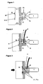
- Figure 1 shows the device for molding micro parts with the mold M open. This is the situation prior to the melting of the plastic material, in which the imprints and/or the mold can be switched at will depending on the type of part to be manufactured.
- the device is located in a position in which the inlet of the cavities 31, 31a of the mold M are not connected to the outlet of the chamber 32, having the tip 1a of the sonotrode inserted.
- This figure shows a mold M with two mold cavities 31, 31a intended for forming two parts, the number of parts added to the mold M being variable; a chamber 32 separated a certain distance from the mold M and an ultrasonic vibration element or sonotrode 1 known in and of itself. This is the situation prior to the melting in which the imprints and/or the mold M can be switched at will depending on the type of part to be manufactured.
- Figure 2 shows the device for the injection of micro parts in the closed position of the mold M and the plastic material supply position.
- the device is in a second position in which communication does exist between the cavities 31, 31a, the mold M and the chamber 32.
- Figure 2 therefore also shows how the mold M is in direct contact with the chamber 32. It is also observed that said chamber 32 has two inlets and an outlet.
- the plastic material P will be supplied continuously with a thread or strip, or discontinuously by means of granules, through one of these inlets.
- Figure 3 shows the device for the injection of micro parts in the melting, or plasticization, and injection position.
- the device is in a third position in which communication does exist between the mold M and the chamber 32, and the mold M is furthermore pressed against the sonotrode 1.
- the plastic material P will melt due to the combined and simultaneous effects of the pressure of the mold M and the action of the ultrasound.
- the mentioned Figure 2 clearly shows the inlet 16 through which the plastic material will be supplied either continuously with a thread or strip, or discontinuously by means of granules.
- the figure shows a chamber 32 with an access opening 33 comprising a guide configuration which is suitable for allowing the movement of the chamber 32, and with it the mold M, towards the sonotrode 1 when it is in said second position, said guide configuration comprising at least said access opening 33.
- Said chamber 32 comprises a stop configuration, opposite said opening 33 and in communication with said outlet, said stop configuration being suitable for regulating compression with an end of said piston-shaped end portion 1a of the sonotrode and thus stopping the movement of the chamber 32 towards the sonotrode 1.
- the vibration element or sonotrode 1 has a piston-shaped end 1a which is suitable for pressing the plastic from said chamber 32 towards the inside of the mold M through the outlet of the chamber 32 to produce said microinjection.
- the device of the present invention is characterized in that it is associated with a control system suitable for controlling the operation of the sonotrode 1 and the movement of the chamber 32 towards the sonotrode 1 through corresponding drive means.
- Said control system is suited so that the sonotrode 1 works simultaneously to the movement of the chamber 32 to cause the plastic P to melt substantially immediately.
- the proposed ultrasonic device for the injection of micro plastic parts comprises combining:
- the mentioned mold cavity 31 is formed between a first part 18 mobile along a double forward and backward linear path, and a second part 17 of a mold M, this second part 17 being associated, by means of a series of springs and guides, with a plate 10 fixed to the injection machine or press, and the mentioned chamber 32 being configured in this second part.
- the sonotrode 1 is supported by an annular support 9 coaxially coupled thereon and rigidly fixed on a contour contained in a nodal cross section 1c of said sonotrode 1, being fixed by means of a plurality of equally spaced radial screws resting at their tip on the mentioned contour of the sonotrode.
- the annular support 9 has an extended portion or tail 9a which is inserted and fixed inside a member with outer spherical surfaces forming a ball joint 8 which allows a pivoting movement for the assembly of the sonotrode 1 and provides auto-centering of the tip 1a inside the chamber 32.
- Figure 5 shows, in an enlarged view, that the mentioned ball joint 8 is surrounded by a bearing 5 which is in turn arranged inside a housing body 6 closed by a cover 7, this housing body 6 being associated with a support 3 of the sonotrode unit through guiding columns, and springs 4 loaded at a pre-established pressure, providing nuts 2 for such purpose at the ends of the corresponding screws 11 coaxial to the springs 4, compressing the support assembly 9, 8, 6 against the support 3.
- support 3 is arranged parallel to and associated with the fixed plate 10 of the injection machine by means of columns finished with regulating nuts which allow controlling the distance between support 3 and plate 10.
- a first part 18 of the mold M is movable with respect to said second part 17 carrying the chamber 32 to adopt at least two positions, a first position in which the inlet to the cavity 31 or cavities of the mold M is not connected to the outlet of the chamber 32 and a second position in which said communication does exist.
- a guide configuration which is suitable for allowing the movement of the chamber 32 towards the sonotrode 1 upon compression of the second part 17 of the mold M when it is in said second position has been provided in the device that is being described.
- a stop configuration which is suitable for abutting with an end of said piston-shaped portion 1a of the sonotrode, and thus stopping the movement of the chamber 32 towards the sonotrode 1, is also provided.
- the device is associated with a control system suitable for controlling the operation of the sonotrode 1 and the movement of the chamber 32 towards the sonotrode 1 through corresponding drive means.
- This control system is suited so that the sonotrode 1 works simultaneously to the movement of the chamber 32 to cause the plastic to melt substantially immediately.
- the device being described is suitable for automatically receiving plastic through said inlet 16 of the chamber 32, by supplying granules or microgranules in the chamber 32 or by a continuous supply of thread or profile previously obtained by extrusion, and for melting it by the action of the sonotrode 1.
- the proposed device is a complete functional unit suitable for being assembled in mold-carrying plates of an injection machine, by removing the central plasticizing unit and assembling the support bedplate of the sonotrode 1, or in a press.
Abstract
a) a mold cavity configured in a mold (M) having an inlet for supplying plastic material to a chamber with an access opening and said chamber facing the cavity at a distal end in relation to its access opening;
b) a cantilevered ultrasonic vibration element (1) associated with an ultrasound generator, with an end portion or tip inserted tightly into the chamber through the access opening in an axially centered manner;
c) movement means for generating a relative movement between the end portion and said parts of the mold (M) so that so that said end portion engages with the supplied plastic material and exerts a pressure of pre-determined magnitude thereon upon activation of said ultrasonic vibration element.
Description
- The present invention generally relates to a device for manufacturing micro parts by means of molding, which uses ultrasonic vibration as a source of energy for melting and injecting the plastic, at the same time of accessing or filling the mold cavity or cavities with the molten plastic. The plastic is supplied to the device continuously in the form of a thread or strip, or discontinuously by means of granules or microgranules.
- In the present specification, micro part will be understood as a plastic part having a weight less than 1 gram and generally having a range of weights comprised between thousandths of a gram to 1 gram or parts having a greater weight with defined microstructural details.
- The present invention belongs to the chemical industry sector, specifically the field of transforming plastics by molding.
- There is an entire market today which requires parts with weights less than 1g or with greater weights with microstructural details. The electrical engineering, medical, telecommunications, automotive, biotechnological and aerospace markets etc. are developing new applications involving the manufacture of parts with very small dimensions due to the generalized trend towards miniaturizing products.
- Some devices are known in the state of the art which use ultrasound to make it easier to expel parts from the mold, as well as to maintain a process temperature in the mold, even to homogenize the mass previously melted by the conventional system of resistors in the nozzle of the plasticizer. The conventional system consists of an assembly of heating resistors, placed in the plasticizing cylinder which is responsible for heating and melting the thermoplastic.
- In most cases, microinjection machines on the market are simply an escalation of large conventional injection machines.
- Patent
EP-A-0930144 with its equivalentUS 6203747 describes an injection machine aided by ultrasound and the method for using it. Said machine includes an injection cylinder, a typical material conveyance unit, a screw, a piston, and a vibration element connected to said cylinder to produce relative movement between the cylinder and said material conveyance unit. In this invention, the material to be melted is introduced in the cylinder, where it is melted, and is subsequently homogenized by the action of the vibrations. - The mentioned patent does not describe the use of ultrasound to cause the thermoplastic material to completely melt for the injection almost instantaneously, but rather the plastic is previously melted by means of other methods, such as by means of a thermal element, for example, in the case of the analyzed patent, and the ultrasound is applied to mitigate or correct the lack of homogeneity caused by the long time elapsing in said melting process.
- Microinjection machines known on the market generally heat the thermoplastic material supplied in the form of granules or microgranules inside a plasticizing cylinder in which, upon the rotation of a screw, the material is cyclically metered discontinuously and conveyed and melted in order to inject it directly into the mold. Another microinjection system assembles an independent extrusion screw which melts the plastic and passes it to a second chamber to be injected into the mold by means of a piston.
- In both cases, and especially when dealing with micro parts, due to the little injection volume to be made in each piston stroke, there is a serious problem for the polymer if the dwell time of the molten granules inside the plasticizer exceeds their residence capacity in this medium, which is the cause of the molecular degradation of the plastic and of the subsequent reduction of quality and loss in the mechanical characterization of the injected parts, which is aggravated when a larger injectable volume is available in the machines.
- W. Michaeli, A. Spennemann, R. Gatner (2002), New plastification concepts for micro injection molding, Microsystem Technologies 8, 55-57, Springer-Verlag 2002, describes a proposal for plasticizing micro parts by ultrasound and it describes a testing unit. This reference indicates that different parameters of the machine were measured by means of this unit, parameters such as performance of the ultrasound generator, extent and course of the sonotrode, activation power, etc. However, this document does not indicate particular constructive details or details relating to the manner of assembling the sonotrode, and it even raises questions as to assessing how ultrasonic plasticization can be integrated in current injection molding machines.
- Accordingly and based on the aforementioned, it seems necessary to offer an alternative to the state of the art which allows the injected plastic to not degrade on a molecular level, nor does it reduce its quality or entail the need to correct lack of homogeneity caused by the exposure time in the melting step.
- The present invention provides for such purpose a device for the molding micro plastic parts based on the controlled melting of the plastic material by ultrasound. The device has particularly been developed to be adapted to any type of pre-existing conventional injection machine or press having smaller dimensions. This device is furthermore the basis for the development of a new micro part molding machine concept.
- The present invention generally relates to an ultrasonic device which allows turning a small conventional plastic injection machine or press into a machine which melts the plastic almost immediately and extremely homogeneously, thus improving the current state of the art.
- The ultrasonic device proposed uses innovative structural and functional concepts for molding micro plastic parts which allow doing away with a specific microinjection machine, as well as its traditional plasticizer. The device of this invention can furthermore do away with the classic granule format of the thermoplastic material to be supplied in its place by means of continuously supplied plastic thread or any other format that can be wound on a reel.
- The device object of the invention is prepared to be assembled in the mold-carrying plates of any small press without needing the machine to be intended for injecting micro parts.
- The ultrasonic device for molding micro plastic parts of the invention comprises combining:
- a) a mold cavity configured in a mold having an inlet for supplying plastic material to a chamber having an access opening and said chamber facing the cavity at a distal end in relation to its opening;
- b) a sonotrode associated with an ultrasound generator, which acts as a plasticizing unit and is supported in cantilevered manner and with an end portion or tip by way of a piston inserted tightly (with little clearance allowing the vibration of the sonotrode and preventing the melted plastic from coming out of the chamber) into the chamber through its access opening in an axially centered manner;
- c) movement means for generating a relative movement between the end portion of the sonotrode and the mold so that said end portion or tip engages with the supplied plastic material and exerts a pressure of pre-determined magnitude thereon upon activation of said ultrasonic vibration element.
- According to the invention, said inlet for supplying plastic material is a side access to the chamber which comes out into a point spaced from the access opening.
- In a preferred embodiment, the mentioned molding cavity or cavities is/are formed between a first part mobile along a double forward and backward linear path, and a second part of a mold, this second part being associated, by means of a series of springs and guides, with a plate fixed to the injection machine, and the mentioned chamber housing the tip of the sonotrode being configured in this second part.
- The sonotrode is furthermore connected to a part in the form of ball joint which allows a pivoting movement and aids in the auto-centering of the tip of the sonotrode inside the chamber facing the mold cavity.
- According to the principles of the invention, at the time of the final closure, the mold, upon moving a controlled path, applies pressure on the sonotrode, exerting great pressure on the plastic material, the ultrasound acting at the same time, almost immediately melting the plastic in an extremely homogenous manner.
- The rate of injection of the plastic into the mold depends, among other known factors such as the viscosity of the plastic material used, the size of the runner and the inlet diameter, on the rate and pressure in the last step of closing the mold and on the effect of the vibration.
- The ultrasonic device for molding of the invention acts very quickly. The plastic material is pre-compressed, melted and injected at virtually the same time it accesses the small cavities of the mold, preventing its solidification during its travel. Molding is thereby made easier and the quality of the parts is optimized since the shear exerted on a plastic material during conventional plasticization is prevented and all the problems deriving from the dwell time of the material in the plasticizer from its entrance until the material becomes a part are eliminated.
- The foregoing and other advantages and features will be better understood from the following description of the attached drawings showing the proposed ultrasonic device for molding micro parts.
- In said drawings:
-
Figures 1 to 3 are schematic views to illustrate the principles of this invention. -
Figure 4 is a sectioned elevational view showing an embodiment of the proposed ultrasonic device for molding. -
Figure 5 is an enlarged partially sectioned elevational view showing the portion for securing the sonotrode. -
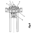
Figure 6 is a plan view of the described device. - The present invention provides an ultrasonic device for molding micro parts using structural and functional concepts for molding plastics which allow simplifying both the structure of the installation and the process and maintenance thereof.
-
Figure 1 shows the device for molding micro parts with the mold M open. This is the situation prior to the melting of the plastic material, in which the imprints and/or the mold can be switched at will depending on the type of part to be manufactured. The device is located in a position in which the inlet of thecavities 31, 31a of the mold M are not connected to the outlet of thechamber 32, having the tip 1a of the sonotrode inserted. This figure shows a mold M with twomold cavities 31, 31a intended for forming two parts, the number of parts added to the mold M being variable; achamber 32 separated a certain distance from the mold M and an ultrasonic vibration element orsonotrode 1 known in and of itself. This is the situation prior to the melting in which the imprints and/or the mold M can be switched at will depending on the type of part to be manufactured. -
Figure 2 shows the device for the injection of micro parts in the closed position of the mold M and the plastic material supply position. The device is in a second position in which communication does exist between thecavities 31, 31a, the mold M and thechamber 32.Figure 2 therefore also shows how the mold M is in direct contact with thechamber 32. It is also observed that saidchamber 32 has two inlets and an outlet. The plastic material P will be supplied continuously with a thread or strip, or discontinuously by means of granules, through one of these inlets. -
Figure 3 shows the device for the injection of micro parts in the melting, or plasticization, and injection position. The device is in a third position in which communication does exist between the mold M and thechamber 32, and the mold M is furthermore pressed against thesonotrode 1. In this situation, the plastic material P will melt due to the combined and simultaneous effects of the pressure of the mold M and the action of the ultrasound. - The mentioned
Figure 2 clearly shows theinlet 16 through which the plastic material will be supplied either continuously with a thread or strip, or discontinuously by means of granules. The figure shows achamber 32 with an access opening 33 comprising a guide configuration which is suitable for allowing the movement of thechamber 32, and with it the mold M, towards thesonotrode 1 when it is in said second position, said guide configuration comprising at least saidaccess opening 33. Saidchamber 32 comprises a stop configuration, opposite saidopening 33 and in communication with said outlet, said stop configuration being suitable for regulating compression with an end of said piston-shaped end portion 1a of the sonotrode and thus stopping the movement of thechamber 32 towards thesonotrode 1. - The vibration element or
sonotrode 1 has a piston-shaped end 1a which is suitable for pressing the plastic from saidchamber 32 towards the inside of the mold M through the outlet of thechamber 32 to produce said microinjection. - The device of the present invention is characterized in that it is associated with a control system suitable for controlling the operation of the
sonotrode 1 and the movement of thechamber 32 towards thesonotrode 1 through corresponding drive means. Said control system is suited so that thesonotrode 1 works simultaneously to the movement of thechamber 32 to cause the plastic P to melt substantially immediately. - With reference to the drawings, the proposed ultrasonic device for the injection of micro plastic parts comprises combining:
- a) at least one
mold cavity 31 configured in a mold M having aninlet 16 for supplying plastic material to achamber 32 with an access opening 33 facing thecavity 31 at a distal end in relation to its opening, saidinlet 16 forming a side access to thechamber 32 which comes out into a point spaced from the access opening 33; - b) an
ultrasonic vibration element 1 which acts as a plasticizing unit and comprises a cantilevered sonotrode associated with an ultrasound generator, with an end portion 1a or tip inserted tightly (with minimal allowance) into thecavity 31 through its access opening in an axially centered manner; - c) movement means for generating a relative movement between the end portion 1a and said parts of the mold M so that said portion 1a engages with the supplied plastic material P and exerts a pressure of pre-determined magnitude thereon upon activation of said ultrasonic vibration element.
- As seen in
Figure 4 , the mentionedmold cavity 31 is formed between afirst part 18 mobile along a double forward and backward linear path, and asecond part 17 of a mold M, thissecond part 17 being associated, by means of a series of springs and guides, with aplate 10 fixed to the injection machine or press, and the mentionedchamber 32 being configured in this second part. - As can be seen in
Figures 4 and5 , thesonotrode 1 is supported by an annular support 9 coaxially coupled thereon and rigidly fixed on a contour contained in anodal cross section 1c of saidsonotrode 1, being fixed by means of a plurality of equally spaced radial screws resting at their tip on the mentioned contour of the sonotrode. The annular support 9 has an extended portion or tail 9a which is inserted and fixed inside a member with outer spherical surfaces forming a ball joint 8 which allows a pivoting movement for the assembly of thesonotrode 1 and provides auto-centering of the tip 1a inside thechamber 32. -
Figure 5 shows, in an enlarged view, that the mentioned ball joint 8 is surrounded by a bearing 5 which is in turn arranged inside ahousing body 6 closed by acover 7, thishousing body 6 being associated with asupport 3 of the sonotrode unit through guiding columns, and springs 4 loaded at a pre-established pressure, providingnuts 2 for such purpose at the ends of the correspondingscrews 11 coaxial to the springs 4, compressing thesupport assembly support 3. - It is also seen that the
support 3 is arranged parallel to and associated with the fixedplate 10 of the injection machine by means of columns finished with regulating nuts which allow controlling the distance betweensupport 3 andplate 10. - According to the most preferred embodiment, a
first part 18 of the mold M is movable with respect to saidsecond part 17 carrying thechamber 32 to adopt at least two positions, a first position in which the inlet to thecavity 31 or cavities of the mold M is not connected to the outlet of thechamber 32 and a second position in which said communication does exist. - A guide configuration which is suitable for allowing the movement of the
chamber 32 towards thesonotrode 1 upon compression of thesecond part 17 of the mold M when it is in said second position has been provided in the device that is being described. - A stop configuration which is suitable for abutting with an end of said piston-shaped portion 1a of the sonotrode, and thus stopping the movement of the
chamber 32 towards thesonotrode 1, is also provided. - The device is associated with a control system suitable for controlling the operation of the
sonotrode 1 and the movement of thechamber 32 towards thesonotrode 1 through corresponding drive means. This control system is suited so that thesonotrode 1 works simultaneously to the movement of thechamber 32 to cause the plastic to melt substantially immediately. - The device being described is suitable for automatically receiving plastic through said
inlet 16 of thechamber 32, by supplying granules or microgranules in thechamber 32 or by a continuous supply of thread or profile previously obtained by extrusion, and for melting it by the action of thesonotrode 1. - As can be seen in
Figure 5 , the proposed device is a complete functional unit suitable for being assembled in mold-carrying plates of an injection machine, by removing the central plasticizing unit and assembling the support bedplate of thesonotrode 1, or in a press. - A person skilled in the art could introduce changes and modifications in the described embodiments without departing from the scope of the invention as it is defined in the attached claims.
Claims (16)
- An ultrasonic device for molding micro plastic parts, of the type which comprises combining:a) at least one mold cavity (31) configured in a mold (M) with at least one inlet (16) for supplying plastic material to a chamber (32) with an access opening (33) and said chamber (32) facing the cavity (31) at a distal end in relation to its access opening (33);b) a cantilevered ultrasonic vibration element (1) associated with an ultrasound generator, with an end portion (1a) or tip inserted tightly into the chamber (32), through its access opening in an axially centered manner;c) movement means for generating a relative movement between the end portion (1a) and said parts of the mold (M) so that said portion (1a) engages with the supplied plastic material and exerts a pressure of pre-determined magnitude thereon upon activation of said ultrasonic vibration element.
- The device according to claim 1, characterized in that said at least one inlet (16) is a side access to the chamber (32) which comes out into a point spaced from the access opening (33).
- The device according to claim 1, characterized in that said ultrasonic vibration element acts as a plasticizing unit and comprises a sonotrode.
- The device according to claim 1, characterized in that the mentioned mold cavity (31) is formed between a first part (18) mobile along a double forward and backward linear path, and a second part (17) of a mold (M), this second part (17) being associated, by means of a series of springs and guides, with a plate (10) fixed to the injection machine or press, and the mentioned chamber (32) being configured in this second part.
- The device according to claim 3, characterized in that the sonotrode (1) is supported by an annular support (9) coaxially coupled thereon and rigidly fixed on a contour contained in a nodal cross section (1c) of said sonotrode (1), being fixed by means of a plurality of equally spaced radial screws resting at their tip on the mentioned contour of the sonotrode, and in that the annular support (9) has an extended portion or tail (9a) which is inserted and fixed inside a member with outer spherical surfaces forming a ball joint (8) which allows a pivoting movement for the assembly of the sonotrode (1) and provides auto-centering of the tip (1a) inside the chamber (32).
- The device according to claim 5, characterized in that the mentioned ball joint (8) is surrounded by a bearing (5) which is in turn arranged inside a housing body (6) closed by a cover (7), this housing body (6) being associated with a support (3) of the sonotrode unit through guiding columns and springs (4).
- The device according to claim 6, characterized in that said springs (4) are loaded at a pre-established pressure, providing nuts (2) for such purpose at the ends of the corresponding screws (11) coaxial to the springs (4), compressing the support assembly (9, 8, 6) against the support (3).
- The device according to claim 6, characterized in that the support (3) is arranged parallel to and associated with the fixed plate (10) of the injection machine or press by means of columns finished with regulating nuts which allow controlling the distance between support (3) and plate (10).
- The device according to claim 4, characterized in that said first part (18) of the mold (M) is movable with respect to said second part (17) carrying the chamber (32) to adopt at least two positions, a first position in which the inlet to the cavity (31) or cavities of the mold (M) is not connected to the outlet of the chamber (32), and a second position in which said communication does exist.
- The device according to claim 9, characterized in that a guide configuration is provided which is suitable for allowing the movement of the chamber (32) towards the sonotrode (1) upon compression of the second part (17) of the mold (M) when it is in said second position.
- The device according to claim 9, characterized in that a stop configuration is provided, which is suitable for abutting with an end of said end portion (1a) of the sonotrode, which has a piston shape, and thus stopping the movement of the chamber (32) towards the sonotrode (1).
- The device according to any one of claims 3 to 11, characterized in that it is associated with a control system suitable for controlling the operation of the sonotrode (1) and the movement of the chamber (32) towards the sonotrode (1) through corresponding drive means.
- The device according to claim 12, characterized in that said control system is suited so that the sonotrode (1) works simultaneously to the movement of the chamber (32) to cause the plastic to melt substantially immediately.
- The device according to claim 2, characterized in that is suited for automatically receiving plastic through said inlet (16) of the chamber (32), by supplying granules or microgranules in the chamber (32) or by a continuous supply (8) of thread or profile previously obtained by extrusion, and for melting it by the action of the sonotrode (1).
- The device according to any one of the previous claims, characterized in that it is a complete functional unit which is suitable for being assembled in mold-carrying plates of an injection machine or press.
- The device according to any of claims 1 to 14, characterized in that it is a complete functional unit equipped with drive means provided for carrying out the movement of the chamber (32) towards the sonotrode (1) or vice versa.
Priority Applications (2)
| Application Number | Priority Date | Filing Date | Title |
|---|---|---|---|
| SI200830713T SI2189264T1 (en) | 2007-08-09 | 2008-08-08 | Ultrasonic device for moulding micro plastic parts |
| PL08828843T PL2189264T3 (en) | 2007-08-09 | 2008-08-08 | Ultrasonic device for moulding micro plastic parts |
Applications Claiming Priority (2)
| Application Number | Priority Date | Filing Date | Title |
|---|---|---|---|
| ES200702245A ES2323624B1 (en) | 2007-08-09 | 2007-08-09 | ULTRASONIC DEVICE FOR MOLDING OF MICROPIEZAS DE PLASTICO. |
| PCT/ES2008/000562 WO2009027569A1 (en) | 2007-08-09 | 2008-08-08 | Ultrasonic device for moulding micro plastic parts |
Publications (3)
| Publication Number | Publication Date |
|---|---|
| EP2189264A1 true EP2189264A1 (en) | 2010-05-26 |
| EP2189264A4 EP2189264A4 (en) | 2011-05-11 |
| EP2189264B1 EP2189264B1 (en) | 2012-05-16 |
Family
ID=40386727
Family Applications (1)
| Application Number | Title | Priority Date | Filing Date |
|---|---|---|---|
| EP08828843A Active EP2189264B1 (en) | 2007-08-09 | 2008-08-08 | Ultrasonic device for moulding micro plastic parts |
Country Status (12)
| Country | Link |
|---|---|
| US (1) | US8328548B2 (en) |
| EP (1) | EP2189264B1 (en) |
| JP (1) | JP5023212B2 (en) |
| CN (1) | CN101801628B (en) |
| BR (1) | BRPI0817030A2 (en) |
| DK (1) | DK2189264T3 (en) |
| ES (2) | ES2323624B1 (en) |
| HK (1) | HK1147227A1 (en) |
| PL (1) | PL2189264T3 (en) |
| PT (1) | PT2189264E (en) |
| SI (1) | SI2189264T1 (en) |
| WO (1) | WO2009027569A1 (en) |
Cited By (6)
| Publication number | Priority date | Publication date | Assignee | Title |
|---|---|---|---|---|
| CN102320088A (en) * | 2011-08-19 | 2012-01-18 | 江苏大学 | Method and device for plasticizing plastics based on Nd: YAG solid state laser |
| EP2471644A1 (en) | 2010-12-31 | 2012-07-04 | Fundació Privada Ascamm | System and method for moulding micro and mini plastic parts |
| NL2009793A (en) * | 2011-11-14 | 2013-05-16 | Fundacio Privada Ascamm | Apparatus for moulding plastic micro-pieces by ultrasound. |
| CN103213257A (en) * | 2013-04-09 | 2013-07-24 | 中南大学 | Screw-free ultrasonic microinjection molding device for molten and plasticized polymer and molding method |
| EP3037235A1 (en) | 2014-12-23 | 2016-06-29 | Fundació Privada Ascamm | Device and method for melted plastic material supply to a mold cavity |
| CN113635527A (en) * | 2021-08-13 | 2021-11-12 | 中南大学 | Novel ultrasonic plasticizing forming device and control method |
Families Citing this family (11)
| Publication number | Priority date | Publication date | Assignee | Title |
|---|---|---|---|---|
| ES2323351B1 (en) | 2007-09-04 | 2010-04-23 | Fundacio Privada Ascamm | DEVICE AND DEVICE FOR SELECTIVE DEPOSITION OF Fused PLASTIC MATTER AND MANUFACTURING METHOD BY SELECTIVE DEPOSITION. |
| CN102357972A (en) * | 2011-10-13 | 2012-02-22 | 重庆大学 | Ultrasonic vibration molding device of superfine plastic component |
| JP5812818B2 (en) * | 2011-11-17 | 2015-11-17 | 株式会社佐藤精機 | Injection molding equipment |
| CN102490301A (en) * | 2011-12-16 | 2012-06-13 | 深圳大学 | Micropart powder compression molding method |
| DE102012014013B4 (en) * | 2012-07-17 | 2022-02-24 | Illinois Tool Works Inc. | Method and device for producing a plastic part, in particular a plastic part for an automobile, in an injection molding process |
| DE102013216855B4 (en) * | 2013-08-23 | 2022-10-20 | Mühlbauer Technology Gmbh | Device and method for the production of shaped bodies |
| ITUA20163828A1 (en) * | 2016-05-26 | 2017-11-26 | Gd Spa | Sonotrode for ultrasonic welding of plastic components of an electronic cigarette |
| WO2020100008A1 (en) | 2018-11-13 | 2020-05-22 | Sabic Global Technologies B.V. | Method of injection molding a thermoplastic article |
| CN110103430B (en) * | 2019-05-29 | 2024-01-26 | 中南大学 | Ultrasonic plasticizing system for micro injection molding |
| CN112848039A (en) * | 2021-01-07 | 2021-05-28 | 迈杰科输配电设备江苏有限公司 | Production equipment and processing technology of special-shaped shell |
| CN114434739B (en) * | 2022-01-27 | 2023-03-31 | 中南大学 | Micro-injection compression molding device and method based on ultrasonic plasticization |
Citations (4)
| Publication number | Priority date | Publication date | Assignee | Title |
|---|---|---|---|---|
| US4115489A (en) * | 1977-06-24 | 1978-09-19 | Textron, Inc. | Plasticizing and molding articles from polymer strip |
| US4784591A (en) * | 1986-07-28 | 1988-11-15 | Ackermann Walter T | Die set and apparatus for in-situ molding of a separable fastener component |
| WO1989003298A1 (en) * | 1987-10-15 | 1989-04-20 | Schunk Maschinen Und Automation Gmbh | Process and device for manufacturing mouldings from particulate materials |
| JPH06328451A (en) * | 1993-05-21 | 1994-11-29 | Sumitomo Electric Ind Ltd | Resin molding method |
Family Cites Families (25)
| Publication number | Priority date | Publication date | Assignee | Title |
|---|---|---|---|---|
| JPS5642637A (en) * | 1979-09-14 | 1981-04-20 | Matsushita Electric Works Ltd | Plasticizing and injecting device for injection molder |
| US4559810A (en) * | 1981-07-09 | 1985-12-24 | Applied Polymer Technology, Inc. | Method for determining resin viscosity with ultrasonic waves |
| US4509360A (en) * | 1983-06-24 | 1985-04-09 | Massachusetts Institute Of Technology | On-line measurement of fluid mixtures |
| JPS6064811A (en) * | 1983-09-21 | 1985-04-13 | Inoue Japax Res Inc | Apparatus for molding resin |
| SE454683B (en) * | 1984-01-02 | 1988-05-24 | Tetra Pak Ab | Ultrasonic Sealing Device |
| DE3571577D1 (en) * | 1984-02-06 | 1989-08-24 | Inoue Japax Res | Injection molding machine with auxiliary packing means |
| IL102556A (en) * | 1991-08-16 | 1998-02-08 | Johnson & Johnson Vision Prod | Apparatus and method for releasably fusing mold lens pieces |
| JPH0584781A (en) * | 1991-09-27 | 1993-04-06 | Mitsubishi Heavy Ind Ltd | Plasticizing device |
| CA2078277C (en) * | 1992-09-15 | 1999-09-14 | Luc Piche | Ultrasonic characterization of polymer melts under processing conditions |
| TW283114B (en) * | 1994-09-16 | 1996-08-11 | Nissei Zyushi Kogyo Kk | |
| JPH0924519A (en) * | 1995-07-12 | 1997-01-28 | Hajime Nitsukou | Gateless molding of thermoplastic resin product and gateless molding device |
| JP3493878B2 (en) * | 1996-03-21 | 2004-02-03 | 松下電工株式会社 | Injection molding method |
| US5951163A (en) * | 1996-10-16 | 1999-09-14 | National Research Council Of Canada | Ultrasonic sensors for on-line monitoring of castings and molding processes at elevated temperatures |
| US6296385B1 (en) * | 1997-05-12 | 2001-10-02 | Mississippi State University | Apparatus and method for high temperature viscosity and temperature measurements |
| JP3232035B2 (en) * | 1997-12-05 | 2001-11-26 | 日精樹脂工業株式会社 | Control method of screw type injection device |
| DE19802874A1 (en) | 1998-01-20 | 1999-07-22 | Mannesmann Ag | Injection molding machine and method for operating such |
| US6227040B1 (en) * | 1998-02-03 | 2001-05-08 | Caldon, Inc. | Method and apparatus for determining the viscosity of a fluid in a container |
| US6629831B2 (en) * | 1999-04-16 | 2003-10-07 | Coach Wei | Apparatus for altering the physical properties of fluids |
| US6361733B1 (en) * | 1999-09-22 | 2002-03-26 | Delphi Technologies, Inc. | Ultrasonic injection molding |
| US6828371B2 (en) * | 2002-01-11 | 2004-12-07 | Ford Global Technologies, Llc | Method for producing a well-exfoliated and dispersed polymer silicate nanocomposite by ultrasonication |
| WO2003074254A1 (en) * | 2002-02-28 | 2003-09-12 | Scimed Life Systems, Inc. | Ultrasonic assisted apparatus and process |
| DE20215458U1 (en) * | 2002-10-08 | 2003-01-16 | Battenfeld Gmbh | Apparatus for producing microstructures comprises injection unit, tool having cavity, and tempering unit having generator for producing short waves and unit for transmitting short waves |
| US7685861B2 (en) * | 2006-10-18 | 2010-03-30 | Luna InnovationsIncorporated | Method and apparatus for calibrating an ultrasonic sensing system used to detect moving objects |
| DE102009004946B4 (en) * | 2008-10-22 | 2015-04-09 | Sikora Aktiengesellschaft | Method and device for measuring the temperature of a plasticized plastic at the exit of an extruder |
| EP2266776A1 (en) * | 2009-06-27 | 2010-12-29 | Bayer MaterialScience AG | Method and device for producing thick-walled plastic components, in particular optical components |
-
2007
- 2007-08-09 ES ES200702245A patent/ES2323624B1/en not_active Expired - Fee Related
-
2008
- 2008-08-08 ES ES08828843T patent/ES2386503T3/en active Active
- 2008-08-08 SI SI200830713T patent/SI2189264T1/en unknown
- 2008-08-08 US US12/672,732 patent/US8328548B2/en active Active
- 2008-08-08 JP JP2010519482A patent/JP5023212B2/en active Active
- 2008-08-08 DK DK08828843.6T patent/DK2189264T3/en active
- 2008-08-08 EP EP08828843A patent/EP2189264B1/en active Active
- 2008-08-08 PL PL08828843T patent/PL2189264T3/en unknown
- 2008-08-08 CN CN200880106775XA patent/CN101801628B/en active Active
- 2008-08-08 BR BRPI0817030-4A patent/BRPI0817030A2/en not_active Application Discontinuation
- 2008-08-08 WO PCT/ES2008/000562 patent/WO2009027569A1/en active Application Filing
- 2008-08-08 PT PT08828843T patent/PT2189264E/en unknown
-
2011
- 2011-02-11 HK HK11101339.5A patent/HK1147227A1/en unknown
Patent Citations (4)
| Publication number | Priority date | Publication date | Assignee | Title |
|---|---|---|---|---|
| US4115489A (en) * | 1977-06-24 | 1978-09-19 | Textron, Inc. | Plasticizing and molding articles from polymer strip |
| US4784591A (en) * | 1986-07-28 | 1988-11-15 | Ackermann Walter T | Die set and apparatus for in-situ molding of a separable fastener component |
| WO1989003298A1 (en) * | 1987-10-15 | 1989-04-20 | Schunk Maschinen Und Automation Gmbh | Process and device for manufacturing mouldings from particulate materials |
| JPH06328451A (en) * | 1993-05-21 | 1994-11-29 | Sumitomo Electric Ind Ltd | Resin molding method |
Non-Patent Citations (2)
| Title |
|---|
| GÄRTNER, R.: "Tagungsbeitrag: Analyse von neuen Plastifizierungskonzepten für das Mikrospritzgiessen", 21. INTERNATIONALES KUNSTSTOFFTECHNISCHES KOLLOQIUM 27.02.-01.03.2002, 28 February 2002 (2002-02-28), pages 1-19, XP002623337, Eurogress Aachen * |
| See also references of WO2009027569A1 * |
Cited By (13)
| Publication number | Priority date | Publication date | Assignee | Title |
|---|---|---|---|---|
| EP2471644A1 (en) | 2010-12-31 | 2012-07-04 | Fundació Privada Ascamm | System and method for moulding micro and mini plastic parts |
| CN102320088A (en) * | 2011-08-19 | 2012-01-18 | 江苏大学 | Method and device for plasticizing plastics based on Nd: YAG solid state laser |
| CN102320088B (en) * | 2011-08-19 | 2014-04-09 | 江苏大学 | Method and device for plasticizing plastics based on Nd: YAG solid state laser |
| NL2009793A (en) * | 2011-11-14 | 2013-05-16 | Fundacio Privada Ascamm | Apparatus for moulding plastic micro-pieces by ultrasound. |
| AT13493U1 (en) * | 2011-11-14 | 2014-01-15 | Fundacio Privada Ascamm | Ultrasonic device for forming micro-plastic parts |
| CN103213257A (en) * | 2013-04-09 | 2013-07-24 | 中南大学 | Screw-free ultrasonic microinjection molding device for molten and plasticized polymer and molding method |
| EP3037235A1 (en) | 2014-12-23 | 2016-06-29 | Fundació Privada Ascamm | Device and method for melted plastic material supply to a mold cavity |
| WO2016103016A1 (en) | 2014-12-23 | 2016-06-30 | Fundació Privada Ascamm | Device and method for feeding molten plastic material into a molding cavity |
| CN107438505A (en) * | 2014-12-23 | 2017-12-05 | 超声公司 | For molten plastic material to be injected to the device and method of die cavity |
| CN107438505B (en) * | 2014-12-23 | 2019-08-20 | 超声公司 | For molten plastic material to be injected to the device and method of die cavity |
| US10953570B2 (en) * | 2014-12-23 | 2021-03-23 | Ultrasion Sl | Device and method for feeding molten plastic material into a molding cavity |
| CN113635527A (en) * | 2021-08-13 | 2021-11-12 | 中南大学 | Novel ultrasonic plasticizing forming device and control method |
| CN113635527B (en) * | 2021-08-13 | 2022-05-13 | 中南大学 | Ultrasonic plasticizing forming device and control method |
Also Published As
| Publication number | Publication date |
|---|---|
| EP2189264A4 (en) | 2011-05-11 |
| CN101801628B (en) | 2013-07-03 |
| SI2189264T1 (en) | 2012-09-28 |
| BRPI0817030A2 (en) | 2020-07-21 |
| US8328548B2 (en) | 2012-12-11 |
| JP5023212B2 (en) | 2012-09-12 |
| DK2189264T3 (en) | 2012-07-23 |
| JP2010535652A (en) | 2010-11-25 |
| WO2009027569A1 (en) | 2009-03-05 |
| EP2189264B1 (en) | 2012-05-16 |
| ES2323624A1 (en) | 2009-07-21 |
| PT2189264E (en) | 2012-07-23 |
| ES2323624B1 (en) | 2011-01-31 |
| HK1147227A1 (en) | 2011-08-05 |
| CN101801628A (en) | 2010-08-11 |
| PL2189264T3 (en) | 2012-10-31 |
| US20100272843A1 (en) | 2010-10-28 |
| ES2386503T3 (en) | 2012-08-22 |
Similar Documents
| Publication | Publication Date | Title |
|---|---|---|
| US8328548B2 (en) | Ultrasonic device for moulding micro plastic parts | |
| JP2000238094A (en) | Injection molder for thermoplastic resin | |
| US6361733B1 (en) | Ultrasonic injection molding | |
| US20060145395A1 (en) | Molding method, mold for molding, molded product, and molding machine | |
| JP2007001268A (en) | Preplasticizing type injection molding apparatus | |
| EP1829664A1 (en) | Molding method, molding machine, and molded product | |
| JP5932159B1 (en) | Injection molding method, screw of injection molding machine and injection molding machine | |
| EP2125349A1 (en) | Plastic lens molding method | |
| JP2923220B2 (en) | Method and apparatus for molding resin material containing long glass fiber | |
| KR910007645A (en) | Injection molding method and apparatus | |
| CN209971342U (en) | Ultrasonic plasticizing micro-injection molding machine main body | |
| JP2022112677A (en) | Injection molding device and molding tool for injection molding | |
| JP2001162649A (en) | Method and apparatus for manufacturing sandwich foam | |
| US11780135B2 (en) | Injection molding apparatus and mold of injection molding apparatus | |
| US20060099299A1 (en) | Plasticizing unit for micro injection molding machine | |
| JP2014087986A (en) | Apparatus and method for injection molding of resin material containing fiber material | |
| US11911946B2 (en) | Injection molding machine and injection molding method | |
| CN110103401B (en) | Ultrasonic plasticizing micro-injection molding machine main body and molding method | |
| CN111936289B (en) | Method for injection molding and injection molding tool | |
| US8992069B2 (en) | Plasticizing system including opposite-facing surfaces for contacting opposite sides of solidified-resin particle | |
| JP3146473B2 (en) | Link by injection molding | |
| JP2023148242A (en) | Injection molding machine | |
| JPH081731A (en) | Plasticization device and method of thermoplastic resin | |
| JP6923359B2 (en) | Injection molding method | |
| JP2017213709A (en) | Injection molding device for fiber-reinforced thermoplastic resin composition |
Legal Events
| Date | Code | Title | Description |
|---|---|---|---|
| PUAI | Public reference made under article 153(3) epc to a published international application that has entered the european phase |
Free format text: ORIGINAL CODE: 0009012 |
|
| 17P | Request for examination filed |
Effective date: 20100224 |
|
| AK | Designated contracting states |
Kind code of ref document: A1 Designated state(s): AT BE BG CH CY CZ DE DK EE ES FI FR GB GR HR HU IE IS IT LI LT LU LV MC MT NL NO PL PT RO SE SI SK TR |
|
| AX | Request for extension of the european patent |
Extension state: AL BA MK RS |
|
| DAX | Request for extension of the european patent (deleted) | ||
| A4 | Supplementary search report drawn up and despatched |
Effective date: 20110412 |
|
| RIC1 | Information provided on ipc code assigned before grant |
Ipc: B29C 45/56 20060101ALI20110406BHEP Ipc: B29C 35/02 20060101ALI20110406BHEP Ipc: B29B 13/08 20060101ALI20110406BHEP Ipc: B29B 13/02 20060101ALI20110406BHEP Ipc: B29C 45/53 20060101ALI20110406BHEP Ipc: B29C 45/46 20060101ALI20110406BHEP Ipc: B29C 45/02 20060101AFI20110406BHEP |
|
| REG | Reference to a national code |
Ref country code: DE Ref legal event code: R079 Ref document number: 602008015721 Country of ref document: DE Free format text: PREVIOUS MAIN CLASS: B29C0033060000 Ipc: B29C0045020000 |
|
| GRAP | Despatch of communication of intention to grant a patent |
Free format text: ORIGINAL CODE: EPIDOSNIGR1 |
|
| RIC1 | Information provided on ipc code assigned before grant |
Ipc: B29C 45/56 20060101ALI20111206BHEP Ipc: B29C 35/02 20060101ALI20111206BHEP Ipc: B29B 13/08 20060101ALI20111206BHEP Ipc: B29B 13/02 20060101ALI20111206BHEP Ipc: B29C 45/53 20060101ALI20111206BHEP Ipc: B29C 45/46 20060101ALI20111206BHEP Ipc: B29C 45/02 20060101AFI20111206BHEP |
|
| RTI1 | Title (correction) |
Free format text: ULTRASONIC DEVICE FOR MOULDING MICRO PLASTIC PARTS |
|
| GRAS | Grant fee paid |
Free format text: ORIGINAL CODE: EPIDOSNIGR3 |
|
| GRAA | (expected) grant |
Free format text: ORIGINAL CODE: 0009210 |
|
| AK | Designated contracting states |
Kind code of ref document: B1 Designated state(s): AT BE BG CH CY CZ DE DK EE ES FI FR GB GR HR HU IE IS IT LI LT LU LV MC MT NL NO PL PT RO SE SI SK TR |
|
| REG | Reference to a national code |
Ref country code: GB Ref legal event code: FG4D |
|
| REG | Reference to a national code |
Ref country code: CH Ref legal event code: EP |
|
| REG | Reference to a national code |
Ref country code: AT Ref legal event code: REF Ref document number: 557848 Country of ref document: AT Kind code of ref document: T Effective date: 20120615 |
|
| REG | Reference to a national code |
Ref country code: IE Ref legal event code: FG4D |
|
| REG | Reference to a national code |
Ref country code: NL Ref legal event code: T3 |
|
| REG | Reference to a national code |
Ref country code: DE Ref legal event code: R096 Ref document number: 602008015721 Country of ref document: DE Effective date: 20120719 |
|
| REG | Reference to a national code |
Ref country code: DK Ref legal event code: T3 Ref country code: PT Ref legal event code: SC4A Free format text: AVAILABILITY OF NATIONAL TRANSLATION Effective date: 20120717 |
|
| REG | Reference to a national code |
Ref country code: SE Ref legal event code: TRGR |
|
| REG | Reference to a national code |
Ref country code: ES Ref legal event code: FG2A Ref document number: 2386503 Country of ref document: ES Kind code of ref document: T3 Effective date: 20120822 |
|
| REG | Reference to a national code |
Ref country code: NO Ref legal event code: T2 Effective date: 20120516 |
|
| REG | Reference to a national code |
Ref country code: LT Ref legal event code: MG4D Effective date: 20120516 |
|
| PG25 | Lapsed in a contracting state [announced via postgrant information from national office to epo] |
Ref country code: CY Free format text: LAPSE BECAUSE OF FAILURE TO SUBMIT A TRANSLATION OF THE DESCRIPTION OR TO PAY THE FEE WITHIN THE PRESCRIBED TIME-LIMIT Effective date: 20120516 Ref country code: IS Free format text: LAPSE BECAUSE OF FAILURE TO SUBMIT A TRANSLATION OF THE DESCRIPTION OR TO PAY THE FEE WITHIN THE PRESCRIBED TIME-LIMIT Effective date: 20120916 Ref country code: LT Free format text: LAPSE BECAUSE OF FAILURE TO SUBMIT A TRANSLATION OF THE DESCRIPTION OR TO PAY THE FEE WITHIN THE PRESCRIBED TIME-LIMIT Effective date: 20120516 |
|
| REG | Reference to a national code |
Ref country code: PL Ref legal event code: T3 |
|
| REG | Reference to a national code |
Ref country code: SK Ref legal event code: T3 Ref document number: E 12342 Country of ref document: SK |
|
| PG25 | Lapsed in a contracting state [announced via postgrant information from national office to epo] |
Ref country code: LV Free format text: LAPSE BECAUSE OF FAILURE TO SUBMIT A TRANSLATION OF THE DESCRIPTION OR TO PAY THE FEE WITHIN THE PRESCRIBED TIME-LIMIT Effective date: 20120516 Ref country code: HR Free format text: LAPSE BECAUSE OF FAILURE TO SUBMIT A TRANSLATION OF THE DESCRIPTION OR TO PAY THE FEE WITHIN THE PRESCRIBED TIME-LIMIT Effective date: 20120516 |
|
| REG | Reference to a national code |
Ref country code: CH Ref legal event code: NV Representative=s name: MARKS AND CLERK (LUXEMBOURG) LLP, CH |
|
| PG25 | Lapsed in a contracting state [announced via postgrant information from national office to epo] |
Ref country code: RO Free format text: LAPSE BECAUSE OF FAILURE TO SUBMIT A TRANSLATION OF THE DESCRIPTION OR TO PAY THE FEE WITHIN THE PRESCRIBED TIME-LIMIT Effective date: 20120516 Ref country code: EE Free format text: LAPSE BECAUSE OF FAILURE TO SUBMIT A TRANSLATION OF THE DESCRIPTION OR TO PAY THE FEE WITHIN THE PRESCRIBED TIME-LIMIT Effective date: 20120516 |
|
| REG | Reference to a national code |
Ref country code: HU Ref legal event code: AG4A Ref document number: E014703 Country of ref document: HU |
|
| PLBE | No opposition filed within time limit |
Free format text: ORIGINAL CODE: 0009261 |
|
| STAA | Information on the status of an ep patent application or granted ep patent |
Free format text: STATUS: NO OPPOSITION FILED WITHIN TIME LIMIT |
|
| PG25 | Lapsed in a contracting state [announced via postgrant information from national office to epo] |
Ref country code: MC Free format text: LAPSE BECAUSE OF NON-PAYMENT OF DUE FEES Effective date: 20120831 |
|
| 26N | No opposition filed |
Effective date: 20130219 |
|
| REG | Reference to a national code |
Ref country code: IE Ref legal event code: MM4A |
|
| PG25 | Lapsed in a contracting state [announced via postgrant information from national office to epo] |
Ref country code: IT Free format text: LAPSE BECAUSE OF NON-PAYMENT OF DUE FEES Effective date: 20120808 |
|
| REG | Reference to a national code |
Ref country code: DE Ref legal event code: R097 Ref document number: 602008015721 Country of ref document: DE Effective date: 20130219 |
|
| PG25 | Lapsed in a contracting state [announced via postgrant information from national office to epo] |
Ref country code: BG Free format text: LAPSE BECAUSE OF FAILURE TO SUBMIT A TRANSLATION OF THE DESCRIPTION OR TO PAY THE FEE WITHIN THE PRESCRIBED TIME-LIMIT Effective date: 20120816 Ref country code: IE Free format text: LAPSE BECAUSE OF NON-PAYMENT OF DUE FEES Effective date: 20120808 |
|
| PG25 | Lapsed in a contracting state [announced via postgrant information from national office to epo] |
Ref country code: MT Free format text: LAPSE BECAUSE OF FAILURE TO SUBMIT A TRANSLATION OF THE DESCRIPTION OR TO PAY THE FEE WITHIN THE PRESCRIBED TIME-LIMIT Effective date: 20120516 |
|
| PG25 | Lapsed in a contracting state [announced via postgrant information from national office to epo] |
Ref country code: TR Free format text: LAPSE BECAUSE OF FAILURE TO SUBMIT A TRANSLATION OF THE DESCRIPTION OR TO PAY THE FEE WITHIN THE PRESCRIBED TIME-LIMIT Effective date: 20120516 |
|
| PG25 | Lapsed in a contracting state [announced via postgrant information from national office to epo] |
Ref country code: GR Free format text: LAPSE BECAUSE OF FAILURE TO SUBMIT A TRANSLATION OF THE DESCRIPTION OR TO PAY THE FEE WITHIN THE PRESCRIBED TIME-LIMIT Effective date: 20120516 |
|
| PGFP | Annual fee paid to national office [announced via postgrant information from national office to epo] |
Ref country code: SK Payment date: 20150731 Year of fee payment: 8 Ref country code: PT Payment date: 20150803 Year of fee payment: 8 Ref country code: CZ Payment date: 20150805 Year of fee payment: 8 Ref country code: NO Payment date: 20150827 Year of fee payment: 8 |
|
| PGFP | Annual fee paid to national office [announced via postgrant information from national office to epo] |
Ref country code: SI Payment date: 20150803 Year of fee payment: 8 Ref country code: HU Payment date: 20150808 Year of fee payment: 8 |
|
| REG | Reference to a national code |
Ref country code: DE Ref legal event code: R082 Ref document number: 602008015721 Country of ref document: DE Representative=s name: DOMPATENT VON KREISLER SELTING WERNER - PARTNE, DE Ref country code: DE Ref legal event code: R082 Ref document number: 602008015721 Country of ref document: DE Representative=s name: VON KREISLER SELTING WERNER - PARTNERSCHAFT VO, DE Ref country code: DE Ref legal event code: R081 Ref document number: 602008015721 Country of ref document: DE Owner name: ULTRASION SL, ES Free format text: FORMER OWNER: FUNDACIO PRIVADA ASCAMM, CERDANYOLA DEL VALLES, ES Ref country code: DE Ref legal event code: R081 Ref document number: 602008015721 Country of ref document: DE Owner name: FUNDACIO EURECAT, CERDANYOLA DEL VALLES, ES Free format text: FORMER OWNER: FUNDACIO PRIVADA ASCAMM, CERDANYOLA DEL VALLES, ES |
|
| REG | Reference to a national code |
Ref country code: DE Ref legal event code: R082 Ref document number: 602008015721 Country of ref document: DE Representative=s name: DOMPATENT VON KREISLER SELTING WERNER - PARTNE, DE Ref country code: DE Ref legal event code: R081 Ref document number: 602008015721 Country of ref document: DE Owner name: ULTRASION SL, ES Free format text: FORMER OWNER: FUNDACIO EURECAT, CERDANYOLA DEL VALLES, BARCELONA, ES |
|
| REG | Reference to a national code |
Ref country code: FR Ref legal event code: PLFP Year of fee payment: 9 |
|
| REG | Reference to a national code |
Ref country code: ES Ref legal event code: PC2A Owner name: FUNDACIO EURECAT Effective date: 20161219 |
|
| REG | Reference to a national code |
Ref country code: NL Ref legal event code: PD Owner name: ULTRASION, SL; ES Free format text: DETAILS ASSIGNMENT: CHANGE OF OWNER(S), ASSIGNMENT; FORMER OWNER NAME: FUNDACIO PRIVADA ASCAMM Effective date: 20161213 |
|
| REG | Reference to a national code |
Ref country code: ES Ref legal event code: PC2A Owner name: ULTRASION, SL Effective date: 20170203 |
|
| REG | Reference to a national code |
Ref country code: GB Ref legal event code: 732E Free format text: REGISTERED BETWEEN 20170119 AND 20170125 |
|
| REG | Reference to a national code |
Ref country code: NO Ref legal event code: MMEP |
|
| PG25 | Lapsed in a contracting state [announced via postgrant information from national office to epo] |
Ref country code: HU Free format text: LAPSE BECAUSE OF NON-PAYMENT OF DUE FEES Effective date: 20160809 Ref country code: NO Free format text: LAPSE BECAUSE OF NON-PAYMENT OF DUE FEES Effective date: 20160831 |
|
| REG | Reference to a national code |
Ref country code: SK Ref legal event code: MM4A Ref document number: E 12342 Country of ref document: SK Effective date: 20160808 |
|
| REG | Reference to a national code |
Ref country code: FR Ref legal event code: TP Owner name: ULTRASION S.L., ES Effective date: 20170412 |
|
| REG | Reference to a national code |
Ref country code: FR Ref legal event code: TP Owner name: ULTRASION S.L., ES Effective date: 20170425 |
|
| PG25 | Lapsed in a contracting state [announced via postgrant information from national office to epo] |
Ref country code: SI Free format text: LAPSE BECAUSE OF NON-PAYMENT OF DUE FEES Effective date: 20160809 Ref country code: PT Free format text: LAPSE BECAUSE OF NON-PAYMENT OF DUE FEES Effective date: 20170208 Ref country code: CZ Free format text: LAPSE BECAUSE OF NON-PAYMENT OF DUE FEES Effective date: 20160808 Ref country code: SK Free format text: LAPSE BECAUSE OF NON-PAYMENT OF DUE FEES Effective date: 20160808 |
|
| REG | Reference to a national code |
Ref country code: SI Ref legal event code: KO00 Effective date: 20170418 |
|
| REG | Reference to a national code |
Ref country code: FR Ref legal event code: PLFP Year of fee payment: 10 |
|
| REG | Reference to a national code |
Ref country code: FR Ref legal event code: PLFP Year of fee payment: 11 |
|
| PGFP | Annual fee paid to national office [announced via postgrant information from national office to epo] |
Ref country code: NL Payment date: 20230826 Year of fee payment: 16 Ref country code: LU Payment date: 20230828 Year of fee payment: 16 |
|
| PGFP | Annual fee paid to national office [announced via postgrant information from national office to epo] |
Ref country code: GB Payment date: 20230828 Year of fee payment: 16 Ref country code: FI Payment date: 20230825 Year of fee payment: 16 Ref country code: ES Payment date: 20230928 Year of fee payment: 16 Ref country code: CH Payment date: 20230903 Year of fee payment: 16 Ref country code: AT Payment date: 20230821 Year of fee payment: 16 |
|
| PGFP | Annual fee paid to national office [announced via postgrant information from national office to epo] |
Ref country code: SE Payment date: 20230827 Year of fee payment: 16 Ref country code: PL Payment date: 20230821 Year of fee payment: 16 Ref country code: FR Payment date: 20230831 Year of fee payment: 16 Ref country code: DK Payment date: 20230829 Year of fee payment: 16 Ref country code: DE Payment date: 20230829 Year of fee payment: 16 Ref country code: BE Payment date: 20230828 Year of fee payment: 16 |