EP2190515B9 - Medical catheter assembly with deflection pull ring and distal tip interlock - Google Patents
Medical catheter assembly with deflection pull ring and distal tip interlock Download PDFInfo
- Publication number
- EP2190515B9 EP2190515B9 EP08865610.3A EP08865610A EP2190515B9 EP 2190515 B9 EP2190515 B9 EP 2190515B9 EP 08865610 A EP08865610 A EP 08865610A EP 2190515 B9 EP2190515 B9 EP 2190515B9
- Authority
- EP
- European Patent Office
- Prior art keywords
- pull ring
- catheter assembly
- pull
- shaft
- tip
- Prior art date
- Legal status (The legal status is an assumption and is not a legal conclusion. Google has not performed a legal analysis and makes no representation as to the accuracy of the status listed.)
- Active
Links
Images


Classifications
-
- A—HUMAN NECESSITIES
- A61—MEDICAL OR VETERINARY SCIENCE; HYGIENE
- A61M—DEVICES FOR INTRODUCING MEDIA INTO, OR ONTO, THE BODY; DEVICES FOR TRANSDUCING BODY MEDIA OR FOR TAKING MEDIA FROM THE BODY; DEVICES FOR PRODUCING OR ENDING SLEEP OR STUPOR
- A61M25/00—Catheters; Hollow probes
- A61M25/01—Introducing, guiding, advancing, emplacing or holding catheters
- A61M25/0105—Steering means as part of the catheter or advancing means; Markers for positioning
- A61M25/0133—Tip steering devices
- A61M25/0147—Tip steering devices with movable mechanical means, e.g. pull wires
-
- A—HUMAN NECESSITIES
- A61—MEDICAL OR VETERINARY SCIENCE; HYGIENE
- A61B—DIAGNOSIS; SURGERY; IDENTIFICATION
- A61B18/00—Surgical instruments, devices or methods for transferring non-mechanical forms of energy to or from the body
- A61B18/04—Surgical instruments, devices or methods for transferring non-mechanical forms of energy to or from the body by heating
- A61B18/12—Surgical instruments, devices or methods for transferring non-mechanical forms of energy to or from the body by heating by passing a current through the tissue to be heated, e.g. high-frequency current
- A61B18/14—Probes or electrodes therefor
- A61B18/1492—Probes or electrodes therefor having a flexible, catheter-like structure, e.g. for heart ablation
-
- A—HUMAN NECESSITIES
- A61—MEDICAL OR VETERINARY SCIENCE; HYGIENE
- A61B—DIAGNOSIS; SURGERY; IDENTIFICATION
- A61B17/00—Surgical instruments, devices or methods, e.g. tourniquets
- A61B17/00234—Surgical instruments, devices or methods, e.g. tourniquets for minimally invasive surgery
- A61B2017/00292—Surgical instruments, devices or methods, e.g. tourniquets for minimally invasive surgery mounted on or guided by flexible, e.g. catheter-like, means
- A61B2017/003—Steerable
-
- A—HUMAN NECESSITIES
- A61—MEDICAL OR VETERINARY SCIENCE; HYGIENE
- A61B—DIAGNOSIS; SURGERY; IDENTIFICATION
- A61B18/00—Surgical instruments, devices or methods for transferring non-mechanical forms of energy to or from the body
- A61B18/04—Surgical instruments, devices or methods for transferring non-mechanical forms of energy to or from the body by heating
- A61B18/12—Surgical instruments, devices or methods for transferring non-mechanical forms of energy to or from the body by heating by passing a current through the tissue to be heated, e.g. high-frequency current
- A61B18/14—Probes or electrodes therefor
- A61B2018/1472—Probes or electrodes therefor for use with liquid electrolyte, e.g. virtual electrodes
-
- A—HUMAN NECESSITIES
- A61—MEDICAL OR VETERINARY SCIENCE; HYGIENE
- A61M—DEVICES FOR INTRODUCING MEDIA INTO, OR ONTO, THE BODY; DEVICES FOR TRANSDUCING BODY MEDIA OR FOR TAKING MEDIA FROM THE BODY; DEVICES FOR PRODUCING OR ENDING SLEEP OR STUPOR
- A61M25/00—Catheters; Hollow probes
- A61M25/01—Introducing, guiding, advancing, emplacing or holding catheters
- A61M25/0105—Steering means as part of the catheter or advancing means; Markers for positioning
- A61M25/0133—Tip steering devices
- A61M25/0147—Tip steering devices with movable mechanical means, e.g. pull wires
- A61M2025/015—Details of the distal fixation of the movable mechanical means
Definitions
- the present invention relates to medical catheter assemblies, and in particular to medical catheter assemblies which utilize a deflection pull ring adjacent a distal tip at the distal end of the catheter shaft to bend the deflectable catheter shaft and move the distal tip in a desired direction.
- Medical catheter assemblies used in the diagnosis or treatment of various medical abnormalities are in common use in medical facilities throughout the world. They generally include a deflectable catheter shaft that can be inserted in and extended along a suitable vein or artery of person being diagnosed or treated to a desired site; a handle actuator which supports a proximal end of the catheter shaft; a distal tip which is connected to the distal end of the catheter shaft and which includes a specialized tip element for the appropriate diagnosis or treatment; and a pull ring assembly which includes a pull ring near the distal end of the catheter shaft and pull wires which extend from the pull ring through the catheter shaft back to the handle actuator for tilting or rocking the pull ring upon manual operation of the handle actuator and consequential pulling of the pull wires, i.e., for deflecting a distal end portion of the catheter shaft with distal tip in a desired direction.
- Ablation catheter assemblies are a category of medical catheter assembly used to ablate tissue, e.g., in the treatment of heart malfunctions. They can be irrigated (discharge ablation fluid in addition to ablation energy) or non-irrigated (discharge of ablation energy but not fluid).
- the distal tip will include a tip electrode as the specialized tip element and an energy source will be connected to their handle actuator to supply energy to the tip electrode.
- a fluid manifold is attached to, or is one-piece with, the tip electrode, and a fluid source is attached to their handle actuator to supply ablation fluid thereto.
- the distal tip can include a mounting shaft which cooperates with the distal end of the adjacent deflectable catheter shaft for connection thereto.
- EP 1 205 208 A1 discloses a deflectable catheter having a handle that can be modified for unidirectional or multidirectional deflection.
- the pull wire is anchored in the distal end of the catheter body.
- the catheter comprises a plurality of pull wires and a plurality of corresponding pull wire anchors.
- EP 0 982 047 A2 discloses a bidirectional steerable catheter comprising a catheter body, a tip section and a control handle.
- US 6,926,669 B 1 discloses a steerable electrophysiology catheter for use in mapping and/or ablation of accessory pathways in myocardial tissue of the heart wall and methods of use thereof.
- WO 97/29801 discloses a reduced stiffness, bidirectionally deflecting catheter assembly including a handle and a flexible catheter shaft with a tip section secured to its distal end.
- the tip section has a radially offset, longitudinally extending core wire lumen through which a tapered core wire, extending from a core wire manipulator on the handle, passes.
- the core wire manipulator can be moved in two different directions to pull or push on the core wire to cause the tip section to deflect axially in opposite directions in the same plane.
- the ends of the core wire are non-rotatably secured to the handle and the tip section so that rotating the handle about its axis causes the tip section to deflect laterally due to torsional forces exerted on the tip section by both the catheter shaft and the core wire.
- the taper on the core wire determines the size and shape of the curved tip section when the tip is axially deflected.
- the distal tip is constructed to include guide channels for the pull wires of the pull wire assembly such that the pull wires will initially extend from the pull ring to the which they are attached towards the tip element (in the case of an irrigated or non-irrigated ablation catheter assembly a tip electrode), and then loop back toward and through the catheter shaft via the guides channels to the handle actuator.
- Such a construction results in the pull ring of the pull ring assembly being moved towards the tip element with operation (pulling) of the pull wires. It also results in dissipated (reduced) forces applied to the braze or weld connecting the pull wires to the pull ring such that failure of the pull ring assembly will only occur near the tensile stress limit of the pull wires themselves.
- Fig. 1 shows an irrigated ablation catheter system 10 according to a preferred embodiment of the present invention. It includes an irrigated ablation catheter assembly 12 connected to an energy source 130 and a fluid source 140.
- the irrigated ablation catheter assembly 12 includes a catheter 20, a handle actuator 120 which supports a proximate end of the catheter 20, a distal tip 30 attached to a distal end of the catheter and a pull ring assembly 50.
- the distal tip 30 includes a tip electrode 31, a fluid manifold 33 and a mounting shaft 38.
- the fluid manifold 33 is attached to the tip electrode with adhesive (in another embodiment the fluid manifold and the tip electrode can be one piece).
- the mounting shaft 38 is one piece with the fluid manifold 33, and it extends into the hollow interior 23 of the catheter shaft 21. It has a smaller diameter than that of the fluid manifold (which is cylindrical in shape), thus leaving an outer annular ledge 34 on a rear face of the fluid manifold.
- the mounting shaft defines a central axial passageway 39 for ablation fluid supplied by a fluid delivery tube (not shown) in the catheter shaft.
- the fluid manifold 33 defines a central axial passageway 35 which is an extension of the central axial passageway 39, and delivery channels 36 that extend from the axial passageway 35 to orifices 37 spaced around its periphery (in another embodiment only one delivery channel leading to one orifice is employed). Fluid supplied to the axial passageway 39 in the mounting shaft will flow to the axial passageway 35 and then through delivery channels 36 to orifices 37 for discharge around the distal tip.
- the tip electrode 31 includes a channel 32 which will deliver fluid from the axial passageway 35 to its distal end. It can be made of platinum or other well-known materials.
- Guide channels 41 and 42 are provided in the mounting shaft 38 at diametrically-opposed locations.
- the guide channel 41 includes a curved section 41a and a rectilinear section 41b.
- the curved section 41a has an inlet opening in the outer surface of the mounting shaft near fluid manifold 33 and the rectilinear section 41b has an outlet opening at the free end 40 of the mounting shaft.
- the guide channel 42 has corresponding sections 42a and 42b. The pull wires of the pull ring assembly respectively extend through these guide channels.
- the pull ring assembly 50 includes a pull ring 51 and pull wires 52 and 53 attached to diametrically opposite locations on an inner face of the pull ring by a solder or weld joint 54.
- the pull wires are flat along at least a portion of their length, in particular at their distal ends, otherwise round. Other configurations are possible.
- the pull ring 51 is positioned between the distal end 22 of the catheter shaft 21 and the outer annular ledge 34 of the fluid manifold, and the pull wires extend from the pull ring toward the fluid manifold and then loop back respectively in and through the guide channels 41 and 42 to the handle actuator 120.
- Pulling of the pull wires 52, 53 by the handle actuator during use of the catheter assembly will cause the pull ring to tilt or rock, thereby bending the catheter shaft 21, and also pulling the pull ring 51 toward contact with the outer annular ledge 34 of the fluid manifold 33.
- the distal tip 60 includes a specialized tip element 61 (in an ablation catheter assembly a tip electrode) and a mounting shaft 62 having a distal portion 63 and a proximal portion 67.
- the proximal portion 67 includes barbs 68 in its outer surface to grip the distal end of the catheter shaft 21a, and axial grooves (guide channels) 69, 70 at diametrically opposed locations. The barbs could be replaced by surface protrusions of varying configurations.
- the distal portion 63 includes an annular flange 64 having axial guide channels 65 and 66 therethrough which are aligned with axial grooves 69 and 70.
- the pull ring 72 of pull ring assembly 71 is positioned between the distal end of catheter shaft 21a and an outer annular ledge 61a of the tip element 61, and the pull wires 73 and 74 attached to diametrically opposed locations on its inner face extend toward the tip electrode and then loop back through respective guide channels 65, 69 and 66, 70 to a handle actuator.
- a compression ring 100 compresses a distal end portion of catheter shaft 21 b against an outer surface of mounting shaft 82, which is one piece with the tip element 81, and the pull wires 93 and 94 of pull ring assembly 91 extend toward the tip element 81 of distal tip 80 and then loop back toward the catheter shaft and pass through respective axial grooves (guide channels) 95, 96 in the outer surface of the mounting shaft.
- the compression ring 100 has a generally rectangular cross-section.
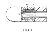
- the compression ring 110 defines a generally flat surface 111 facing inwardly toward the mounting shaft and a generally convex outwardly facing surface 112.
- the pull ring assembly may include more than two pull wires attached to the pull ring around its circumference, with corresponding guide channels provided in the distal tip to guide the individual pull wires first toward the tip element of the distal tip and then to loop back to the handle actuator.
- the compression ring as shown in Figs. 5 and 6 could have shapes other than those specifically depicted.
Description
- The present invention relates to medical catheter assemblies, and in particular to medical catheter assemblies which utilize a deflection pull ring adjacent a distal tip at the distal end of the catheter shaft to bend the deflectable catheter shaft and move the distal tip in a desired direction.
- Medical catheter assemblies used in the diagnosis or treatment of various medical abnormalities are in common use in medical facilities throughout the world. They generally include a deflectable catheter shaft that can be inserted in and extended along a suitable vein or artery of person being diagnosed or treated to a desired site; a handle actuator which supports a proximal end of the catheter shaft; a distal tip which is connected to the distal end of the catheter shaft and which includes a specialized tip element for the appropriate diagnosis or treatment; and a pull ring assembly which includes a pull ring near the distal end of the catheter shaft and pull wires which extend from the pull ring through the catheter shaft back to the handle actuator for tilting or rocking the pull ring upon manual operation of the handle actuator and consequential pulling of the pull wires, i.e., for deflecting a distal end portion of the catheter shaft with distal tip in a desired direction.
- Ablation catheter assemblies are a category of medical catheter assembly used to ablate tissue, e.g., in the treatment of heart malfunctions. They can be irrigated (discharge ablation fluid in addition to ablation energy) or non-irrigated (discharge of ablation energy but not fluid). The distal tip will include a tip electrode as the specialized tip element and an energy source will be connected to their handle actuator to supply energy to the tip electrode. In irrigated catheter assemblies a fluid manifold is attached to, or is one-piece with, the tip electrode, and a fluid source is attached to their handle actuator to supply ablation fluid thereto. In either, the distal tip can include a mounting shaft which cooperates with the distal end of the adjacent deflectable catheter shaft for connection thereto.
-
EP 1 205 208 A1 discloses a deflectable catheter having a handle that can be modified for unidirectional or multidirectional deflection. The pull wire is anchored in the distal end of the catheter body. For multidirectional deflection, the catheter comprises a plurality of pull wires and a plurality of corresponding pull wire anchors. -
EP 0 982 047 A2 discloses a bidirectional steerable catheter comprising a catheter body, a tip section and a control handle. -
US 6,926,669 B 1 discloses a steerable electrophysiology catheter for use in mapping and/or ablation of accessory pathways in myocardial tissue of the heart wall and methods of use thereof. -
WO 97/29801 - It has been found that the operation of such medical catheter assemblies, including irrigated or non-irrigated ablation catheter assemblies, can become compromised over time with creeping of the pull ring towards the handle actuator (and away from the distal tip) due to repeated tilting or rocking thereof by the pull wires. In addition, failure of the medical catheter assemblies can occur with separation of the pull wires from the pull rings of the pull ring assemblies due to stress failure of the braze or weld joints therebetween.
- It is thus an object of the present invention to provide a medical catheter assembly (including an irrigated or non-irrigated ablation catheter assembly) which is constructed such that creeping of the pull ring towards the handle actuator (and away from the distal tip) is prevented.
- It is another object of the present invention to provide a medical catheter assembly (including an irrigated or non-irrigated catheter assembly) which is constructed such that stress on the connecting joints between the pull wires and pull ring is reduced, reducing failure of medical catheter assembly due to failure of the pull ring assembly.
- These and other objects are achieved with a medical catheter assembly wherein the distal tip is constructed to include guide channels for the pull wires of the pull wire assembly such that the pull wires will initially extend from the pull ring to the which they are attached towards the tip element (in the case of an irrigated or non-irrigated ablation catheter assembly a tip electrode), and then loop back toward and through the catheter shaft via the guides channels to the handle actuator. This creates a distal tip and pull ring interlock. Such a construction results in the pull ring of the pull ring assembly being moved towards the tip element with operation (pulling) of the pull wires. It also results in dissipated (reduced) forces applied to the braze or weld connecting the pull wires to the pull ring such that failure of the pull ring assembly will only occur near the tensile stress limit of the pull wires themselves.
- The invention will be better understood by reference to the attached drawings, taken in conjunction with the following discussion.
-
-
Fig. 1 is an isometric view of an irrigated ablation catheter system that includes an ablation catheter assembly, an energy source and a fluid source in accordance with a first embodiment of the present invention; -
Fig. 2 is an enlarged side view of the distal end portion of the deflectable ablation catheter shaft, the pull ring assembly and distal tip of the catheter ofFig. 1 ; -
Fig. 3 is an enlarged detail ofFig. 2 ; -
Fig. 4 is a side view, partly in section, of a distal end portion of a catheter shaft, a pull ring assembly and a distal tip according to a second embodiment of the invention, and -
Figs. 5 and6 show side views of third and fourth embodiments. -
Fig. 1 shows an irrigatedablation catheter system 10 according to a preferred embodiment of the present invention. It includes an irrigatedablation catheter assembly 12 connected to anenergy source 130 and afluid source 140. - The irrigated
ablation catheter assembly 12 includes acatheter 20, ahandle actuator 120 which supports a proximate end of thecatheter 20, adistal tip 30 attached to a distal end of the catheter and apull ring assembly 50. - As seen in
Figs. 2 and 3 , thedistal tip 30 includes atip electrode 31, afluid manifold 33 and amounting shaft 38. Thefluid manifold 33 is attached to the tip electrode with adhesive (in another embodiment the fluid manifold and the tip electrode can be one piece). Themounting shaft 38 is one piece with thefluid manifold 33, and it extends into thehollow interior 23 of thecatheter shaft 21. It has a smaller diameter than that of the fluid manifold (which is cylindrical in shape), thus leaving an outerannular ledge 34 on a rear face of the fluid manifold. The mounting shaft defines a centralaxial passageway 39 for ablation fluid supplied by a fluid delivery tube (not shown) in the catheter shaft. Thefluid manifold 33 defines a centralaxial passageway 35 which is an extension of the centralaxial passageway 39, anddelivery channels 36 that extend from theaxial passageway 35 to orifices 37 spaced around its periphery (in another embodiment only one delivery channel leading to one orifice is employed). Fluid supplied to theaxial passageway 39 in the mounting shaft will flow to theaxial passageway 35 and then throughdelivery channels 36 to orifices 37 for discharge around the distal tip. Thetip electrode 31 includes achannel 32 which will deliver fluid from theaxial passageway 35 to its distal end. It can be made of platinum or other well-known materials. -
Guide channels mounting shaft 38 at diametrically-opposed locations. Theguide channel 41 includes acurved section 41a and arectilinear section 41b. Thecurved section 41a has an inlet opening in the outer surface of the mounting shaft nearfluid manifold 33 and therectilinear section 41b has an outlet opening at thefree end 40 of the mounting shaft. Theguide channel 42 hascorresponding sections - The
pull ring assembly 50 includes apull ring 51 andpull wires weld joint 54. The pull wires are flat along at least a portion of their length, in particular at their distal ends, otherwise round. Other configurations are possible. Thepull ring 51 is positioned between thedistal end 22 of thecatheter shaft 21 and the outerannular ledge 34 of the fluid manifold, and the pull wires extend from the pull ring toward the fluid manifold and then loop back respectively in and through theguide channels handle actuator 120. Pulling of thepull wires catheter shaft 21, and also pulling thepull ring 51 toward contact with the outerannular ledge 34 of thefluid manifold 33. - Turning now to the embodiment of
Fig. 4 , thedistal tip 60 includes a specialized tip element 61 (in an ablation catheter assembly a tip electrode) and amounting shaft 62 having adistal portion 63 and aproximal portion 67. Theproximal portion 67 includesbarbs 68 in its outer surface to grip the distal end of thecatheter shaft 21a, and axial grooves (guide channels) 69, 70 at diametrically opposed locations. The barbs could be replaced by surface protrusions of varying configurations. Thedistal portion 63 includes anannular flange 64 havingaxial guide channels axial grooves pull ring 72 ofpull ring assembly 71 is positioned between the distal end ofcatheter shaft 21a and an outer annular ledge 61a of thetip element 61, and thepull wires respective guide channels - In the embodiment of
Fig. 5 , acompression ring 100 compresses a distal end portion ofcatheter shaft 21 b against an outer surface ofmounting shaft 82, which is one piece with thetip element 81, and thepull wires pull ring assembly 91 extend toward thetip element 81 ofdistal tip 80 and then loop back toward the catheter shaft and pass through respective axial grooves (guide channels) 95, 96 in the outer surface of the mounting shaft. Thecompression ring 100 has a generally rectangular cross-section. - In the embodiment of
Fig. 6 , which is similar to that ofFig. 5 , thecompression ring 110 defines a generallyflat surface 111 facing inwardly toward the mounting shaft and a generally convex outwardly facingsurface 112. - Although a detailed explanation of various embodiments of the invention have been provided, changes therein can be made and still fall within the scope of the present invention. For example, the pull ring assembly may include more than two pull wires attached to the pull ring around its circumference, with corresponding guide channels provided in the distal tip to guide the individual pull wires first toward the tip element of the distal tip and then to loop back to the handle actuator. Also, the compression ring as shown in
Figs. 5 and6 could have shapes other than those specifically depicted. - The followig are specific examples of the invention :
- 1. A medical catheter assembly which comprises:
- a deflectable catheter shaft defining a distal end and a hollow interior;
- a distal tip at said distal end of said catheter shaft and including a tip element and a mounting shaft which extends into the hollow interior of said catheter shaft; and
- a pull ring assembly comprising a pull ring and pull wires attached thereto, said pull ring being positioned around said mounting shaft;
- said distal tip providing guide channels through which said pull wires are respectively guided so as to initially extend from said pull ring toward said tip element and then loop back toward and through said catheter shaft, such that pulling of said pull wires to cause said pull ring to bend said catheter shaft and said pull ring to move toward said tip element.
- 2. The medical catheter assembly of example 1, wherein said mounting shaft includes an outwardly-extending annular flange having axially-extending passageways therethrough which comprise said guide channels.
- 3. The medical catheter assembly of example 2, wherein said mounting shaft includes a distal portion connected to said tip element and a proximal portion which extends into said catheter shaft, wherein said outwardly-extending annular flange is one piece with said distal portion, and wherein said proximal portion includes surface protrusions to grip said catheter shaft.
- 4. The medical catheter assembly of example 3, wherein said surface protrusions comprise barbs.
- 5. The medical catheter assembly of example 4, wherein said axial grooves are provided in said barbs in alignment with said axial passageways and comprise said guide channels.
- 6. The medical catheter assembly of example 1, including a compression ring which compresses a distal end portion of said catheter shaft against an outer surface of said mounting shaft.
- 7. The medical catheter assembly of example 6, wherein said outer surface of said mounting shaft includes axial grooves therein which comprise said guide channels.
- 8. The medical catheter assembly of example 7; wherein said compression ring has a generally rectangular cross section.
- 9. The medical catheter assembly of example 7, wherein said compression ring has a generally flat surface facing inwardly toward said mounting shaft and a generally convex outwardly facing surface.
- 10. The medical catheter assembly of example 1, wherein said tip element defines an outer annular ledge and said pull ring is located between said catheter shaft and said outer annular ledge.
- 11. The medical catheter assembly of example 1, wherein said distal tip includes two guide channels on diametrically opposite sides thereof.
- 12. The medical catheter assembly of example 11, wherein said pull ring assembly includes two pull wires attached to diametrically opposite locations on said pull ring.
- 13. The medical catheter assembly of example 1, wherein each pull wire is flat along at least a portion of its length.
- 14. The medical catheter assembly of example 1, wherein each pull wire is connected to an inner surface of said pull ring.
- 15. The medical catheter assembly of example 14, wherein each pull wire is connected to the pull ring by a weld.
- 16. An ablation catheter assembly which comprises:
- a deflectable catheter shaft defining a distal end and a hollow interior;
- a distal tip at said distal end of said catheter shaft and including a tip electrode and amounting shaft which extends into said catheter shaft;
- a pull ring assembly comprising a pull ring and pull wires attached thereto, said pull ring being position around said mounting shaft;
- said distal tip providing guide channels through which said pull wires are respectively guided so as to initially extend from said pull ring toward said tip electrode and then loop back toward and through said catheter shaft, such that pulling of said pull wires to cause said pull ring to bend said catheter shaft will cause said pull ring to interlock with said tip electrode.
- 17. The ablation catheter assembly of example 16, wherein said distal tip includes a fluid manifold between said tip electrode and said mounting shaft, and wherein each of said guide channels includes a curved section and a rectilinear section in said mounting shaft.
- 18. The ablation catheter assembly of example 17, comprising two guide channels on diametrically opposite sides of said distal tip, and wherein said pull ring assembly includes two pull wires attached to diametrically opposite locations on said pull ring.
- 19. The ablation catheter assembly of example 17, wherein said mounting shaft and said tip electrode are one-piece.
- 20. The ablation catheter assembly of example 16, wherein each pull wire is flat along at least a portion of its length.
- 21. The ablation catheter assembly of example 16, wherein each pull wire is connected to an inner surface of said pull ring.
- 22. A combination of a distal tip for attachment to a distal end of a catheter shaft and a pull ring assembly, said pull ring assembly including a pull ring and pull wires connected thereto, said distal tip including a tip electrode and a mounting shaft which defines guide channels for said pull wires such that with said pull ring positioned around said mounting shaft, said pull wires will first extend toward said tip electrode and then loop away therefrom.
Claims (15)
- A medical catheter assembly (12) which comprises:a deflectable catheter shaft (21, 21b) defining a distal end and a hollow interior (23);a distal tip (30, 60, 80) at said distal end of said catheter shaft (21, 21b) and including a tip element (31, 61, 81) and a mounting shaft (38, 62, 82) which extends into the hollow interior (23) of said catheter shaft (21, 21b);a pull ring assembly (50, 71, 91) comprising a pull ring (51, 72, 91) and pull wires (52, 53; 73, 74; 93, 94) attached thereto; andsaid distal tip (30, 60, 80) providing guide channels (41, 42; 95,96) through which said pull wires (52, 53; 73, 74; 93, 94) are respectively guided so as to initially extend from said pull ring (51, 72, 92) toward said tip element (31, 61, 81) and then loop back toward and through said catheter shaft (21, 21b),
wherein the medical catheter assembly (12) is characterized by,
said pull ring (51, 72, 92) being positioned around said mounting shaft (38, 62, 82), and
pulling of said pull wires (52, 53; 73, 74; 93, 94) causes said pull ring (51, 72, 92) to tilt or rock, thereby bending said cather shaft (21, 21b), and also pulling said pull ring (51,72,91) toward said tip element (31,61,81). - The medical catheter assembly (12) of claim 1, wherein said mounting shaft (38, 62, 82) includes an outwardly-extending annular flange (64) having axially-extending passageways (65, 66) therethrough which comprise said guide channels (41, 42; 65, 66; 95, 96).
- The medical catheter assembly (12) of claim 2, wherein said mounting shaft (38, 62, 82) includes a distal portion (63) connected to said tip element (31, 61, 81) and a proximal portion (67) which extends into said catheter shaft (21, 21b), wherein said outwardly-extending annular flange (64) is one piece with said distal portion (63), and wherein said proximal portion (67) includes surface protrusions to grip said catheter shaft, wherein said surface protrusions comprise barbs (68).
- The medical catheter assembly (12) of claim 3, wherein axial grooves (69, 70) are provided in said barbs (68) in alignment with said axial passageways (41, 42; 65, 66; 95, 96) and comprise said guide channels.
- The medical catheter assembly (12) of claim 1, including a compression ring (100,110) which compresses a distal end portion of said catheter shaft (21, 21b) against an outer surface of said mounting shaft (38, 62, 82).
- The medical catheter assembly (12) of claim 5, wherein said outer surface of said mounting shaft (38, 62, 82) includes axial grooves (95, 96) therein which comprise said guide channels.
- The medical catheter assembly (12) of claim 6, wherein said compression ring (100, 110) has a generally rectangular cross section or wherein said compression ring (100, 110) has a generally flat surface (111) facing inwardly toward said mounting shaft (38, 62, 82) and a generally convex outwardly facing surface (112).
- The medical catheter assembly (12) of claim 1, wherein said tip element (31, 61, 81) defines an outer annular ledge (34) and said pull ring (51, 72, 92) is located between said catheter shaft (21, 21b) and said outer annular ledge (34).
- The medical catheter assembly (12) of claim 1, wherein said distal tip (30, 60, 80) includes two guide channels (41, 42; 65, 66; 95, 96) on diametrically opposite sides thereof, wherein preferably said pull ring assembly (50, 71, 91) includes two pull wires (52, 53; 73, 74, 93, 94) attached to diametrically opposite locations on said pull ring (51, 72, 92).
- The medical catheter assembly (12) of claim 1, wherein said pull wires are (52, 53; 73, 74; 93, 94) flat along at least a portion of their length.
- The medical catheter assembly (12) of claim 1, wherein each pull wire (52, 53; 73, 74; 93, 94) is connected to an inner surface of said pull ring (51, 72, 92).
- The medical catheter assembly (12) of claim 11, wherein each pull wire (52, 53; 73, 74; 93, 94) is connected to the pull ring (51, 72, 92) by a weld.
- The medical catheter assembly (12) of any one of the preceding claims, wherein the assembly is an ablation catheter assembly;
said tip element (31, 61, 81) is a tip electrode, and
said pull wires (52, 53; 73, 74; 93, 94) are respectively guided so as to initially extend from said pull ring (51, 72, 92) toward said tip electrode and then loop back toward and through said catheter shaft (21, 21b), such that pulling of said pull wires (52, 53; 73, 74; 93, 94) to cause said pull ring to bend said catheter shaft (21, 21b) will cause said pull ring to interlock with said tip electrode. - The ablation catheter assembly (12) of claim 13, wherein said distal tip (30, 60, 80) includes a fluid manifold (33) between said tip electrode and said mounting shaft (38, 62, 82), and wherein each of said guide channels (41, 42; 65, 66; 95, 96) includes a curved section and a rectilinear section in said mounting shaft (38, 62, 82).
- The ablation catheter assembly (12) of claim 14, wherein said mounting shaft (38, 62, 82) and said tip electrode are one piece.
Applications Claiming Priority (2)
| Application Number | Priority Date | Filing Date | Title |
|---|---|---|---|
| US11/963,441 US8162934B2 (en) | 2007-12-21 | 2007-12-21 | Medical catheter assembly with deflection pull ring and distal tip interlock |
| PCT/US2008/083731 WO2009082570A1 (en) | 2007-12-21 | 2008-11-17 | Medical catheter assembly with deflection pull ring and distal tip interlock |
Publications (4)
| Publication Number | Publication Date |
|---|---|
| EP2190515A1 EP2190515A1 (en) | 2010-06-02 |
| EP2190515A4 EP2190515A4 (en) | 2011-03-16 |
| EP2190515B1 EP2190515B1 (en) | 2013-05-29 |
| EP2190515B9 true EP2190515B9 (en) | 2013-08-28 |
Family
ID=40789513
Family Applications (1)
| Application Number | Title | Priority Date | Filing Date |
|---|---|---|---|
| EP08865610.3A Active EP2190515B9 (en) | 2007-12-21 | 2008-11-17 | Medical catheter assembly with deflection pull ring and distal tip interlock |
Country Status (5)
| Country | Link |
|---|---|
| US (3) | US8162934B2 (en) |
| EP (1) | EP2190515B9 (en) |
| JP (1) | JP5449190B2 (en) |
| CN (1) | CN101932357B (en) |
| WO (1) | WO2009082570A1 (en) |
Families Citing this family (37)
| Publication number | Priority date | Publication date | Assignee | Title |
|---|---|---|---|---|
| US8162934B2 (en) | 2007-12-21 | 2012-04-24 | St. Jude Medical, Atrial Fibrillation Division, Inc. | Medical catheter assembly with deflection pull ring and distal tip interlock |
| EP3970627B1 (en) * | 2011-11-08 | 2023-12-20 | Edwards Lifesciences Innovation (Israel) Ltd. | Controlled steering functionality for implant-delivery tool |
| EP2604305A1 (en) * | 2011-12-16 | 2013-06-19 | VascoMed GmbH | Catheter and method for producing the same |
| US8702647B2 (en) * | 2012-04-19 | 2014-04-22 | Medtronic Ablation Frontiers Llc | Catheter deflection anchor |
| US8814825B2 (en) | 2012-05-07 | 2014-08-26 | St. Jude Medical, Atrial Fibrillation Division, Inc. | Deflectable catheter shaft section, catheter incorporating same, and method of manufacturing same |
| US9861738B2 (en) | 2012-05-07 | 2018-01-09 | St. Jude Medical, Cardiology Division, Inc. | Flex tip fluid lumen assembly with termination tube |
| JP2014023721A (en) * | 2012-07-26 | 2014-02-06 | Japan Lifeline Co Ltd | Electrode catheter |
| US10398499B2 (en) * | 2013-05-24 | 2019-09-03 | Biosense Webster (Israel) Ltd. | Configurable control handle for catheters and other surgical tool |
| US10835183B2 (en) | 2013-07-01 | 2020-11-17 | Zurich Medical Corporation | Apparatus and method for intravascular measurements |
| WO2015003024A2 (en) | 2013-07-01 | 2015-01-08 | Zurich Medical, Inc. | Apparatus and method for intravascular measurements |
| US10118021B2 (en) | 2013-09-30 | 2018-11-06 | St. Jude Medical, Cardiology Division, Inc. | Catheter having an active return-to-straight mechanism |
| WO2016071378A1 (en) * | 2014-11-04 | 2016-05-12 | Koninklijke Philips N.V. | Steerable medical device, and use of a pull wire ring therein |
| JP6673598B2 (en) | 2014-11-19 | 2020-03-25 | エピックス セラピューティクス,インコーポレイテッド | High resolution mapping of tissue with pacing |
| SG11201703943VA (en) | 2014-11-19 | 2017-06-29 | Advanced Cardiac Therapeutics Inc | Ablation devices, systems and methods of using a high-resolution electrode assembly |
| EP3220844B1 (en) | 2014-11-19 | 2020-11-11 | EPiX Therapeutics, Inc. | Systems for high-resolution mapping of tissue |
| CR20170245A (en) * | 2014-12-05 | 2017-09-14 | Edwards Lifesciences Corp | DIRIGIBLE CATETER WITH TRACTION CABLE |
| CN105982733A (en) * | 2015-02-27 | 2016-10-05 | 四川锦江电子科技有限公司 | Controllable multi-electrode ablation device |
| US9636164B2 (en) | 2015-03-25 | 2017-05-02 | Advanced Cardiac Therapeutics, Inc. | Contact sensing systems and methods |
| US9860392B2 (en) | 2015-06-05 | 2018-01-02 | Silicon Laboratories Inc. | Direct-current to alternating-current power conversion |
| US10154905B2 (en) * | 2015-08-07 | 2018-12-18 | Medtronic Vascular, Inc. | System and method for deflecting a delivery catheter |
| CN109068995B (en) | 2016-02-26 | 2022-05-13 | 新宁研究院 | Imaging probe with rotatable core |
| CA3017269A1 (en) | 2016-03-15 | 2017-09-21 | Epix Therapeutics, Inc. | Improved devices, systems and methods for irrigated ablation |
| CN109843181B (en) * | 2016-09-29 | 2022-11-08 | 皇家飞利浦有限公司 | Pull wire crown and crown sleeve for catheter assembly |
| EP3520852A4 (en) * | 2016-09-30 | 2020-08-12 | Nipro Corporation | Catheter |
| US10786651B2 (en) | 2017-03-07 | 2020-09-29 | Talon Medical, LLC | Steerable guide catheter |
| CN110809448B (en) | 2017-04-27 | 2022-11-25 | Epix疗法公司 | Determining properties of contact between catheter tip and tissue |
| KR102137994B1 (en) * | 2017-12-15 | 2020-07-28 | 주식회사 오에스와이메드 | Steerable catater |
| CN108066003A (en) * | 2017-12-29 | 2018-05-25 | 浙江归创医疗器械有限公司 | Ablation catheter |
| JP2021510573A (en) * | 2018-01-11 | 2021-04-30 | ザ ユナイテッド ステイツ ガバメント アズ リプレゼンティド バイ ザ デパートメント オブ ヴェテランズ アフェアーズ | Sampling catheter with articulated tip |
| US20200155807A1 (en) * | 2018-06-07 | 2020-05-21 | The Board Of Trustees Of The Leland Stanford Junior University | Small diameter catheter for introduction into the trachea and other orifices, as well as into passages that are difficult to intubate or access |
| EP3628208A1 (en) * | 2018-09-28 | 2020-04-01 | Ambu A/S | An articulated tip part for an endoscope |
| US11918762B2 (en) | 2018-10-03 | 2024-03-05 | St. Jude Medical, Cardiology Division, Inc. | Reduced actuation force electrophysiology catheter handle |
| EP3636133B1 (en) * | 2018-10-12 | 2024-04-03 | Ambu A/S | An articulated tip part for an endoscope |
| EP4167892A1 (en) | 2020-06-19 | 2023-04-26 | Remedy Robotics, Inc. | Systems and methods for guidance of intraluminal devices within the vasculature |
| DE102021109022A1 (en) * | 2021-04-12 | 2022-10-13 | Karl Storz Se & Co. Kg | Shaft for a flexible endoscope or for a flexible endoscopic instrument |
| US11707332B2 (en) | 2021-07-01 | 2023-07-25 | Remedy Robotics, Inc. | Image space control for endovascular tools |
| WO2023278789A1 (en) | 2021-07-01 | 2023-01-05 | Remedy Robotics, Inc. | Vision-based position and orientation determination for endovascular tools |
Family Cites Families (29)
| Publication number | Priority date | Publication date | Assignee | Title |
|---|---|---|---|---|
| JPH0724083Y2 (en) * | 1988-07-20 | 1995-06-05 | 旭光学工業株式会社 | Mounting structure for bending operation wire of endoscope |
| US5273535A (en) | 1991-11-08 | 1993-12-28 | Ep Technologies, Inc. | Catheter with electrode tip having asymmetric left and right curve configurations |
| US5389073A (en) | 1992-12-01 | 1995-02-14 | Cardiac Pathways Corporation | Steerable catheter with adjustable bend location |
| CA2109980A1 (en) | 1992-12-01 | 1994-06-02 | Mir A. Imran | Steerable catheter with adjustable bend location and/or radius and method |
| US5391147A (en) | 1992-12-01 | 1995-02-21 | Cardiac Pathways Corporation | Steerable catheter with adjustable bend location and/or radius and method |
| US5462527A (en) | 1993-06-29 | 1995-10-31 | C.R. Bard, Inc. | Actuator for use with steerable catheter |
| EP0605796B1 (en) * | 1992-12-04 | 2003-08-13 | C.R. Bard, Inc. | Catheter with independent proximal and distal control |
| US5545200A (en) | 1993-07-20 | 1996-08-13 | Medtronic Cardiorhythm | Steerable electrophysiology catheter |
| US5431168A (en) | 1993-08-23 | 1995-07-11 | Cordis-Webster, Inc. | Steerable open-lumen catheter |
| US6099524A (en) * | 1994-01-28 | 2000-08-08 | Cardiac Pacemakers, Inc. | Electrophysiological mapping and ablation catheter and method |
| US5882333A (en) * | 1994-05-13 | 1999-03-16 | Cardima, Inc. | Catheter with deflectable distal section |
| US5666970A (en) | 1995-05-02 | 1997-09-16 | Heart Rhythm Technologies, Inc. | Locking mechanism for catheters |
| US6113572A (en) * | 1995-05-24 | 2000-09-05 | C. R. Bard, Inc. | Multiple-type catheter connection systems |
| US5807249A (en) | 1996-02-16 | 1998-09-15 | Medtronic, Inc. | Reduced stiffness, bidirectionally deflecting catheter assembly |
| JPH09299320A (en) * | 1996-05-15 | 1997-11-25 | Fuji Photo Optical Co Ltd | Angle device of endoscope |
| US6840936B2 (en) * | 1996-10-22 | 2005-01-11 | Epicor Medical, Inc. | Methods and devices for ablation |
| US5968052A (en) * | 1996-11-27 | 1999-10-19 | Scimed Life Systems Inc. | Pull back stent delivery system with pistol grip retraction handle |
| US6183463B1 (en) | 1997-12-01 | 2001-02-06 | Cordis Webster, Inc. | Bidirectional steerable cathether with bidirectional control handle |
| US6198974B1 (en) * | 1998-08-14 | 2001-03-06 | Cordis Webster, Inc. | Bi-directional steerable catheter |
| US6926669B1 (en) * | 2000-10-10 | 2005-08-09 | Medtronic, Inc. | Heart wall ablation/mapping catheter and method |
| US6571131B1 (en) | 2000-11-10 | 2003-05-27 | Biosense Webster, Inc. | Deflectable catheter with modifiable handle |
| US7235070B2 (en) | 2003-07-02 | 2007-06-26 | St. Jude Medical, Atrial Fibrillation Division, Inc. | Ablation fluid manifold for ablation catheter |
| US7229437B2 (en) | 2003-09-22 | 2007-06-12 | St. Jude Medical, Atrial Fibrillation Division, Inc. | Medical device having integral traces and formed electrodes |
| US7632265B2 (en) * | 2004-05-28 | 2009-12-15 | St. Jude Medical, Atrial Fibrillation Division, Inc. | Radio frequency ablation servo catheter and method |
| US7974674B2 (en) * | 2004-05-28 | 2011-07-05 | St. Jude Medical, Atrial Fibrillation Division, Inc. | Robotic surgical system and method for surface modeling |
| US7740616B2 (en) | 2005-03-29 | 2010-06-22 | Angiodynamics, Inc. | Implantable catheter and method of using same |
| US20080234660A2 (en) * | 2006-05-16 | 2008-09-25 | Sarah Cumming | Steerable Catheter Using Flat Pull Wires and Method of Making Same |
| US20070270679A1 (en) | 2006-05-17 | 2007-11-22 | Duy Nguyen | Deflectable variable radius catheters |
| US8162934B2 (en) | 2007-12-21 | 2012-04-24 | St. Jude Medical, Atrial Fibrillation Division, Inc. | Medical catheter assembly with deflection pull ring and distal tip interlock |
-
2007
- 2007-12-21 US US11/963,441 patent/US8162934B2/en active Active
-
2008
- 2008-11-17 CN CN2008801219288A patent/CN101932357B/en active Active
- 2008-11-17 WO PCT/US2008/083731 patent/WO2009082570A1/en active Application Filing
- 2008-11-17 EP EP08865610.3A patent/EP2190515B9/en active Active
- 2008-11-17 JP JP2010539566A patent/JP5449190B2/en not_active Expired - Fee Related
-
2012
- 2012-04-23 US US13/453,525 patent/US8556893B2/en active Active
-
2013
- 2013-10-10 US US14/051,143 patent/US20140100566A1/en not_active Abandoned
Also Published As
| Publication number | Publication date |
|---|---|
| JP5449190B2 (en) | 2014-03-19 |
| US20090163917A1 (en) | 2009-06-25 |
| EP2190515A4 (en) | 2011-03-16 |
| JP2011507606A (en) | 2011-03-10 |
| US20140100566A1 (en) | 2014-04-10 |
| US8556893B2 (en) | 2013-10-15 |
| WO2009082570A1 (en) | 2009-07-02 |
| EP2190515B1 (en) | 2013-05-29 |
| CN101932357A (en) | 2010-12-29 |
| US8162934B2 (en) | 2012-04-24 |
| EP2190515A1 (en) | 2010-06-02 |
| US20120203170A1 (en) | 2012-08-09 |
| CN101932357B (en) | 2013-12-25 |
Similar Documents
| Publication | Publication Date | Title |
|---|---|---|
| EP2190515B9 (en) | Medical catheter assembly with deflection pull ring and distal tip interlock | |
| US10478597B2 (en) | Medical catheter with deflection pull ring and distal tip attachment apparatus | |
| EP0904796B1 (en) | Omni-directional steerable catheter | |
| US6198974B1 (en) | Bi-directional steerable catheter | |
| US5507725A (en) | Steerable catheter | |
| EP0879613B1 (en) | Deflectable tip electrode catheter | |
| US7077823B2 (en) | Bidirectional steerable catheter with slidable mated puller wires | |
| US9433751B2 (en) | Steerable catheter with distal tip orientation sheaths | |
| EP2544749B1 (en) | Magnetically guided catheter | |
| JP5734562B2 (en) | A deflectable sheath guidance device | |
| US6569114B2 (en) | Steerable catheter with struts | |
| US6551271B2 (en) | Asymmetrical bidirectional steerable catheter | |
| JP2000197642A (en) | Bidirectional electrode catheter | |
| CN109963601B (en) | Inflow cannula | |
| JP6249789B2 (en) | Percutaneous intramyocardial drug infusion catheter and catheter system | |
| EP2827934B1 (en) | System and method for coupling a tube with a medical device handle | |
| JP5561784B2 (en) | Electrode catheter |
Legal Events
| Date | Code | Title | Description |
|---|---|---|---|
| PUAI | Public reference made under article 153(3) epc to a published international application that has entered the european phase |
Free format text: ORIGINAL CODE: 0009012 |
|
| 17P | Request for examination filed |
Effective date: 20100322 |
|
| AK | Designated contracting states |
Kind code of ref document: A1 Designated state(s): AT BE BG CH CY CZ DE DK EE ES FI FR GB GR HR HU IE IS IT LI LT LU LV MC MT NL NO PL PT RO SE SI SK TR |
|
| AX | Request for extension of the european patent |
Extension state: AL BA MK RS |
|
| A4 | Supplementary search report drawn up and despatched |
Effective date: 20110211 |
|
| DAX | Request for extension of the european patent (deleted) | ||
| 17Q | First examination report despatched |
Effective date: 20111028 |
|
| GRAP | Despatch of communication of intention to grant a patent |
Free format text: ORIGINAL CODE: EPIDOSNIGR1 |
|
| GRAS | Grant fee paid |
Free format text: ORIGINAL CODE: EPIDOSNIGR3 |
|
| GRAA | (expected) grant |
Free format text: ORIGINAL CODE: 0009210 |
|
| AK | Designated contracting states |
Kind code of ref document: B1 Designated state(s): AT BE BG CH CY CZ DE DK EE ES FI FR GB GR HR HU IE IS IT LI LT LU LV MC MT NL NO PL PT RO SE SI SK TR |
|
| REG | Reference to a national code |
Ref country code: GB Ref legal event code: FG4D |
|
| REG | Reference to a national code |
Ref country code: CH Ref legal event code: EP |
|
| REG | Reference to a national code |
Ref country code: AT Ref legal event code: REF Ref document number: 613972 Country of ref document: AT Kind code of ref document: T Effective date: 20130615 |
|
| REG | Reference to a national code |
Ref country code: IE Ref legal event code: FG4D |
|
| REG | Reference to a national code |
Ref country code: DE Ref legal event code: R096 Ref document number: 602008025083 Country of ref document: DE Effective date: 20130725 |
|
| REG | Reference to a national code |
Ref country code: AT Ref legal event code: MK05 Ref document number: 613972 Country of ref document: AT Kind code of ref document: T Effective date: 20130529 |
|
| REG | Reference to a national code |
Ref country code: LT Ref legal event code: MG4D |
|
| PG25 | Lapsed in a contracting state [announced via postgrant information from national office to epo] |
Ref country code: AT Free format text: LAPSE BECAUSE OF FAILURE TO SUBMIT A TRANSLATION OF THE DESCRIPTION OR TO PAY THE FEE WITHIN THE PRESCRIBED TIME-LIMIT Effective date: 20130529 Ref country code: NO Free format text: LAPSE BECAUSE OF FAILURE TO SUBMIT A TRANSLATION OF THE DESCRIPTION OR TO PAY THE FEE WITHIN THE PRESCRIBED TIME-LIMIT Effective date: 20130829 Ref country code: GR Free format text: LAPSE BECAUSE OF FAILURE TO SUBMIT A TRANSLATION OF THE DESCRIPTION OR TO PAY THE FEE WITHIN THE PRESCRIBED TIME-LIMIT Effective date: 20130830 Ref country code: ES Free format text: LAPSE BECAUSE OF FAILURE TO SUBMIT A TRANSLATION OF THE DESCRIPTION OR TO PAY THE FEE WITHIN THE PRESCRIBED TIME-LIMIT Effective date: 20130909 Ref country code: FI Free format text: LAPSE BECAUSE OF FAILURE TO SUBMIT A TRANSLATION OF THE DESCRIPTION OR TO PAY THE FEE WITHIN THE PRESCRIBED TIME-LIMIT Effective date: 20130529 Ref country code: PT Free format text: LAPSE BECAUSE OF FAILURE TO SUBMIT A TRANSLATION OF THE DESCRIPTION OR TO PAY THE FEE WITHIN THE PRESCRIBED TIME-LIMIT Effective date: 20130930 Ref country code: LT Free format text: LAPSE BECAUSE OF FAILURE TO SUBMIT A TRANSLATION OF THE DESCRIPTION OR TO PAY THE FEE WITHIN THE PRESCRIBED TIME-LIMIT Effective date: 20130529 Ref country code: IS Free format text: LAPSE BECAUSE OF FAILURE TO SUBMIT A TRANSLATION OF THE DESCRIPTION OR TO PAY THE FEE WITHIN THE PRESCRIBED TIME-LIMIT Effective date: 20130929 Ref country code: SE Free format text: LAPSE BECAUSE OF FAILURE TO SUBMIT A TRANSLATION OF THE DESCRIPTION OR TO PAY THE FEE WITHIN THE PRESCRIBED TIME-LIMIT Effective date: 20130529 Ref country code: SI Free format text: LAPSE BECAUSE OF FAILURE TO SUBMIT A TRANSLATION OF THE DESCRIPTION OR TO PAY THE FEE WITHIN THE PRESCRIBED TIME-LIMIT Effective date: 20130529 |
|
| REG | Reference to a national code |
Ref country code: NL Ref legal event code: VDEP Effective date: 20130529 |
|
| PG25 | Lapsed in a contracting state [announced via postgrant information from national office to epo] |
Ref country code: BG Free format text: LAPSE BECAUSE OF FAILURE TO SUBMIT A TRANSLATION OF THE DESCRIPTION OR TO PAY THE FEE WITHIN THE PRESCRIBED TIME-LIMIT Effective date: 20130829 Ref country code: HR Free format text: LAPSE BECAUSE OF FAILURE TO SUBMIT A TRANSLATION OF THE DESCRIPTION OR TO PAY THE FEE WITHIN THE PRESCRIBED TIME-LIMIT Effective date: 20130529 Ref country code: PL Free format text: LAPSE BECAUSE OF FAILURE TO SUBMIT A TRANSLATION OF THE DESCRIPTION OR TO PAY THE FEE WITHIN THE PRESCRIBED TIME-LIMIT Effective date: 20130529 |
|
| PG25 | Lapsed in a contracting state [announced via postgrant information from national office to epo] |
Ref country code: LV Free format text: LAPSE BECAUSE OF FAILURE TO SUBMIT A TRANSLATION OF THE DESCRIPTION OR TO PAY THE FEE WITHIN THE PRESCRIBED TIME-LIMIT Effective date: 20130529 |
|
| PG25 | Lapsed in a contracting state [announced via postgrant information from national office to epo] |
Ref country code: EE Free format text: LAPSE BECAUSE OF FAILURE TO SUBMIT A TRANSLATION OF THE DESCRIPTION OR TO PAY THE FEE WITHIN THE PRESCRIBED TIME-LIMIT Effective date: 20130529 Ref country code: DK Free format text: LAPSE BECAUSE OF FAILURE TO SUBMIT A TRANSLATION OF THE DESCRIPTION OR TO PAY THE FEE WITHIN THE PRESCRIBED TIME-LIMIT Effective date: 20130529 Ref country code: SK Free format text: LAPSE BECAUSE OF FAILURE TO SUBMIT A TRANSLATION OF THE DESCRIPTION OR TO PAY THE FEE WITHIN THE PRESCRIBED TIME-LIMIT Effective date: 20130529 Ref country code: BE Free format text: LAPSE BECAUSE OF FAILURE TO SUBMIT A TRANSLATION OF THE DESCRIPTION OR TO PAY THE FEE WITHIN THE PRESCRIBED TIME-LIMIT Effective date: 20130529 Ref country code: CZ Free format text: LAPSE BECAUSE OF FAILURE TO SUBMIT A TRANSLATION OF THE DESCRIPTION OR TO PAY THE FEE WITHIN THE PRESCRIBED TIME-LIMIT Effective date: 20130529 |
|
| PG25 | Lapsed in a contracting state [announced via postgrant information from national office to epo] |
Ref country code: RO Free format text: LAPSE BECAUSE OF FAILURE TO SUBMIT A TRANSLATION OF THE DESCRIPTION OR TO PAY THE FEE WITHIN THE PRESCRIBED TIME-LIMIT Effective date: 20130529 Ref country code: NL Free format text: LAPSE BECAUSE OF FAILURE TO SUBMIT A TRANSLATION OF THE DESCRIPTION OR TO PAY THE FEE WITHIN THE PRESCRIBED TIME-LIMIT Effective date: 20130529 |
|
| PLBE | No opposition filed within time limit |
Free format text: ORIGINAL CODE: 0009261 |
|
| STAA | Information on the status of an ep patent application or granted ep patent |
Free format text: STATUS: NO OPPOSITION FILED WITHIN TIME LIMIT |
|
| 26N | No opposition filed |
Effective date: 20140303 |
|
| REG | Reference to a national code |
Ref country code: DE Ref legal event code: R097 Ref document number: 602008025083 Country of ref document: DE Effective date: 20140303 |
|
| REG | Reference to a national code |
Ref country code: CH Ref legal event code: PL |
|
| PG25 | Lapsed in a contracting state [announced via postgrant information from national office to epo] |
Ref country code: MC Free format text: LAPSE BECAUSE OF FAILURE TO SUBMIT A TRANSLATION OF THE DESCRIPTION OR TO PAY THE FEE WITHIN THE PRESCRIBED TIME-LIMIT Effective date: 20130529 Ref country code: LI Free format text: LAPSE BECAUSE OF NON-PAYMENT OF DUE FEES Effective date: 20131130 Ref country code: CH Free format text: LAPSE BECAUSE OF NON-PAYMENT OF DUE FEES Effective date: 20131130 |
|
| REG | Reference to a national code |
Ref country code: IE Ref legal event code: MM4A |
|
| PG25 | Lapsed in a contracting state [announced via postgrant information from national office to epo] |
Ref country code: IE Free format text: LAPSE BECAUSE OF NON-PAYMENT OF DUE FEES Effective date: 20131117 |
|
| PG25 | Lapsed in a contracting state [announced via postgrant information from national office to epo] |
Ref country code: CY Free format text: LAPSE BECAUSE OF FAILURE TO SUBMIT A TRANSLATION OF THE DESCRIPTION OR TO PAY THE FEE WITHIN THE PRESCRIBED TIME-LIMIT Effective date: 20130529 Ref country code: TR Free format text: LAPSE BECAUSE OF FAILURE TO SUBMIT A TRANSLATION OF THE DESCRIPTION OR TO PAY THE FEE WITHIN THE PRESCRIBED TIME-LIMIT Effective date: 20130529 |
|
| PG25 | Lapsed in a contracting state [announced via postgrant information from national office to epo] |
Ref country code: HU Free format text: LAPSE BECAUSE OF FAILURE TO SUBMIT A TRANSLATION OF THE DESCRIPTION OR TO PAY THE FEE WITHIN THE PRESCRIBED TIME-LIMIT; INVALID AB INITIO Effective date: 20081117 Ref country code: LU Free format text: LAPSE BECAUSE OF NON-PAYMENT OF DUE FEES Effective date: 20131117 |
|
| PG25 | Lapsed in a contracting state [announced via postgrant information from national office to epo] |
Ref country code: MT Free format text: LAPSE BECAUSE OF FAILURE TO SUBMIT A TRANSLATION OF THE DESCRIPTION OR TO PAY THE FEE WITHIN THE PRESCRIBED TIME-LIMIT Effective date: 20130529 |
|
| REG | Reference to a national code |
Ref country code: FR Ref legal event code: PLFP Year of fee payment: 8 |
|
| REG | Reference to a national code |
Ref country code: FR Ref legal event code: PLFP Year of fee payment: 9 |
|
| REG | Reference to a national code |
Ref country code: FR Ref legal event code: PLFP Year of fee payment: 10 |
|
| REG | Reference to a national code |
Ref country code: FR Ref legal event code: PLFP Year of fee payment: 11 |
|
| PGFP | Annual fee paid to national office [announced via postgrant information from national office to epo] |
Ref country code: FR Payment date: 20221020 Year of fee payment: 15 |
|
| PGFP | Annual fee paid to national office [announced via postgrant information from national office to epo] |
Ref country code: IT Payment date: 20221111 Year of fee payment: 15 Ref country code: GB Payment date: 20221012 Year of fee payment: 15 Ref country code: DE Payment date: 20221012 Year of fee payment: 15 |
|
| REG | Reference to a national code |
Ref country code: DE Ref legal event code: R082 Ref document number: 602008025083 Country of ref document: DE Representative=s name: ALPSPITZ IP ALLGAYER UND PARTNER PATENTANWAELT, DE |