EP2190519B1 - Medical catheter with deflection pull ring and distal tip attachment means - Google Patents
Medical catheter with deflection pull ring and distal tip attachment means Download PDFInfo
- Publication number
- EP2190519B1 EP2190519B1 EP08865469A EP08865469A EP2190519B1 EP 2190519 B1 EP2190519 B1 EP 2190519B1 EP 08865469 A EP08865469 A EP 08865469A EP 08865469 A EP08865469 A EP 08865469A EP 2190519 B1 EP2190519 B1 EP 2190519B1
- Authority
- EP
- European Patent Office
- Prior art keywords
- shaft
- mounting shaft
- catheter
- pull ring
- catheter assembly
- Prior art date
- Legal status (The legal status is an assumption and is not a legal conclusion. Google has not performed a legal analysis and makes no representation as to the accuracy of the status listed.)
- Not-in-force
Links
Images


Classifications
-
- A—HUMAN NECESSITIES
- A61—MEDICAL OR VETERINARY SCIENCE; HYGIENE
- A61M—DEVICES FOR INTRODUCING MEDIA INTO, OR ONTO, THE BODY; DEVICES FOR TRANSDUCING BODY MEDIA OR FOR TAKING MEDIA FROM THE BODY; DEVICES FOR PRODUCING OR ENDING SLEEP OR STUPOR
- A61M25/00—Catheters; Hollow probes
- A61M25/01—Introducing, guiding, advancing, emplacing or holding catheters
- A61M25/0105—Steering means as part of the catheter or advancing means; Markers for positioning
- A61M25/0133—Tip steering devices
- A61M25/0147—Tip steering devices with movable mechanical means, e.g. pull wires
-
- A—HUMAN NECESSITIES
- A61—MEDICAL OR VETERINARY SCIENCE; HYGIENE
- A61B—DIAGNOSIS; SURGERY; IDENTIFICATION
- A61B18/00—Surgical instruments, devices or methods for transferring non-mechanical forms of energy to or from the body
- A61B18/04—Surgical instruments, devices or methods for transferring non-mechanical forms of energy to or from the body by heating
- A61B18/12—Surgical instruments, devices or methods for transferring non-mechanical forms of energy to or from the body by heating by passing a current through the tissue to be heated, e.g. high-frequency current
- A61B18/14—Probes or electrodes therefor
- A61B18/1492—Probes or electrodes therefor having a flexible, catheter-like structure, e.g. for heart ablation
-
- A—HUMAN NECESSITIES
- A61—MEDICAL OR VETERINARY SCIENCE; HYGIENE
- A61B—DIAGNOSIS; SURGERY; IDENTIFICATION
- A61B17/00—Surgical instruments, devices or methods, e.g. tourniquets
- A61B17/00234—Surgical instruments, devices or methods, e.g. tourniquets for minimally invasive surgery
- A61B2017/00292—Surgical instruments, devices or methods, e.g. tourniquets for minimally invasive surgery mounted on or guided by flexible, e.g. catheter-like, means
- A61B2017/003—Steerable
-
- A—HUMAN NECESSITIES
- A61—MEDICAL OR VETERINARY SCIENCE; HYGIENE
- A61B—DIAGNOSIS; SURGERY; IDENTIFICATION
- A61B18/00—Surgical instruments, devices or methods for transferring non-mechanical forms of energy to or from the body
- A61B18/04—Surgical instruments, devices or methods for transferring non-mechanical forms of energy to or from the body by heating
- A61B18/12—Surgical instruments, devices or methods for transferring non-mechanical forms of energy to or from the body by heating by passing a current through the tissue to be heated, e.g. high-frequency current
- A61B18/14—Probes or electrodes therefor
- A61B2018/1472—Probes or electrodes therefor for use with liquid electrolyte, e.g. virtual electrodes
-
- A—HUMAN NECESSITIES
- A61—MEDICAL OR VETERINARY SCIENCE; HYGIENE
- A61M—DEVICES FOR INTRODUCING MEDIA INTO, OR ONTO, THE BODY; DEVICES FOR TRANSDUCING BODY MEDIA OR FOR TAKING MEDIA FROM THE BODY; DEVICES FOR PRODUCING OR ENDING SLEEP OR STUPOR
- A61M25/00—Catheters; Hollow probes
- A61M25/01—Introducing, guiding, advancing, emplacing or holding catheters
- A61M25/0105—Steering means as part of the catheter or advancing means; Markers for positioning
- A61M25/0133—Tip steering devices
- A61M25/0147—Tip steering devices with movable mechanical means, e.g. pull wires
- A61M2025/015—Details of the distal fixation of the movable mechanical means
Definitions
- the present invention relates to medical catheters, and in particular to ablation catheters which utilize a deflection pull ring near the distal end of a deflectable catheter shaft to bend the catheter shaft and the distal tip attached thereto in a desired direction.
- Medical catheters used in the diagnosis and treatment of various medical conditions are in common use throughout the world. They generally include a deflectable catheter shaft; a handle actuator which supports a proximal end of the catheter shaft; a pull ring assembly which includes a deflection pull ring positioned near the distal end of the catheter shaft and pull wires which extend from the pull ring to the handle actuator; and a distal tip with specialized tip element connected to the distal end of the catheter shaft. Pulling of the pull wires by operation of the handle actuator will tilt or rock the deflection pull ring and cause the catheter shaft to bend in a desired fashion.
- Ablation catheters are a category of medical catheters used to ablate tissue, e.g., in the treatment of heart malfunctions. They can be irrigated (discharge ablation fluid in addition to ablation energy) or non-irrigated (no discharge of ablation fluid therefrom). Their distal tip will include a tip electrode and an energy source is connected to their handle actuator to supply energy to their tip electrode. In irrigated ablation catheters a fluid manifold is attached to, or is one-piece with, the tip electrode, and a fluid source is attached to their handle actuator to supply ablating fluid thereto. Their distal tip can include a mounting shaft which cooperates with the distal end of the adjacent deflectable catheter shaft for connection thereto.
- the distal tips are attached to the distal ends of the catheter shafts using adhesives. It has been found that over time these adhesives can lose their adhesion properties, and the distal tips can become loose. This is a dangerous situation that must be avoided.
- an electrode catheter comprising a tubular body with a distal section having a flexible tubular portion is disclosed.
- the flexible tubular distal section is covered by at least one spirally wrapped flat ribbon electrode.
- Each spirally wrapped flat ribbon electrode has an associated lead wire that can be connected to a source of energy of ablation or connected to a recording system to produce electrophysiologic signals for diagnosis.
- the preferred catheter is steerable by use of a puller wire connected to the distal section and connected to a handle with means for controlling the movement of the puller wire.
- the spirally wound flat ribbon electrode is partially masked with a polyurethane or latex mask.
- attachment means which may include compression ring that compresses the catheter shaft against a mounting shaft of the distal tip to reliably connect the catheter shaft and the distal tip together.
- the compression ring compresses the catheter shaft inwardly against an outer surface of the mounting shaft.
- the compression ring compresses the catheter shaft outwardly against an inner surface of the mounting shaft.
- the attachment means can include an outwardly-extending feature, such as an annular lip, on the mounting shaft to prevent slippage of the mounting shaft past the compression ring.
- the attachment means can also include features such a surface irregularities (e.g., barbs) on the outer surface of the mounting shaft to grip an interior surface of the catheter shaft, or features such as surface irregularities (e.g., barbs) on an interior surface of the mounting shaft to grip the outer surface of the mounting shaft extending therein.
- the compression ring can be an insert within the catheter shaft which is otherwise gripped on its outer surface by a mounting shaft of the distal tip.
- Fig. 1 is an isometric view of an irrigated ablation catheter system which includes an irrigated ablation catheter assembly according to a first embodiment of the present invention
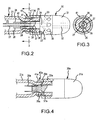
- Fig. 2 is an enlarged side view, partially in section, of the distal end portion of the deflectable catheter shaft, the distal tip and the attachment apparatus of the irrigated ablation catheter assembly of Fig. 1 ;
- Fig. 3 is a sectional view of Fig. 2 as seen along line 3-3 therein;
- Fig. 4 is a side view, partially in section, of a distal end portion of a deflectable catheter shaft, a distal tip and an attachment apparatus of a non-irrigated ablation catheter assembly according to a second embodiment of the present invention
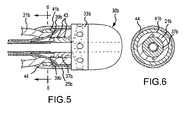
- Fig. 5 is a side view, partially in section, of a distal end portion of a deflectable catheter shaft, a distal tip and an attachment apparatus of an irrigated ablation catheter assembly according to a third embodiment of the present invention
- Fig. 6 is a sectional view of Fig. 5 as seen along line 6-6 therein, and
- Fig. 7 is a side view, partially in section, of the distal end portion of a deflectable catheter shaft, a distal tip and an attachment apparatus of an irrigated ablation catheter assembly according to a fourth embodiment of the present invention.
- Fig. 1 shows an irrigated ablation catheter system 10 according to an embodiment of the present invention. It includes an ablation catheter assembly comprised of an ablation catheter 20, a distal tip 30 attached to the distal end portion of the ablation catheter by attachment apparatus 40, and a handle actuator 50 which supports the proximal end of the ablation catheter 20. As part of the irrigated ablation catheter system 10, an energy source 60 and a fluid source 70 are connected to the handle actuator 50 to supply energy and fluid to the distal tip 30 via the catheter 20.
- Figs. 2 and 3 show a distal end portion of the catheter 20, the distal tip 30 and the attachment apparatus 40.
- the catheter 20 includes a bendable and compressible catheter shaft 21 that defines a distal end 22 and a hollow interior 23. Guide channels 24 extend through the wall of the catheter shaft at diametrically opposed locations near the distal end 22.
- a pull ring assembly includes a deflection pull ring 25 positioned around the shaft 21 near its distal end 22, and pull wires 26 attached to diametrically opposed locations on the pull ring which extend through the guide channels 24 into the hollow interior 23 and back to the handle actuator 50.
- the pull wires 26 are respectively pulled by manual operation of triggers of the handle actuator 50 to cause the pull ring 25 to tilt or rock relative to the catheter shaft and thereby bend the distal end portion of the catheter shaft in a first direction or in a second, opposite direction in a known manner.
- a fluid delivery tube 27 extends from the handle actuator 50 through the hollow interior 23 towards the distal end 22 and is supplied with fluid by the fluid source 70.
- the distal tip 30 includes a tip electrode 31, a fluid manifold 33 and a mounting shaft 37.
- the mounting shaft 37 is one piece with the fluid manifold 33 and it extends into the hollow interior 23 of the catheter shaft. It includes a central axial passageway 38 into which the fluid delivery tube 27 sealingly extends, as well as axial channels 39 in its outer surface at diametrically opposed locations and in which the pull wires 26 can extend.
- the fluid manifold 33 which is cylindrical in shape, defines a central axial passageway 34 which is an extension of the axial passageway 38, and channels 35 that extend from the axial passageway 34 to orifices 36 spaced around its periphery. Fluid supplied to the axial passageway 38 from the fluid delivery tube 27 will flow to the axial passageway 34, then through channels 35 to orifices 36 to be discharged therefrom. In an alternate embodiment the fluid manifold will include only one channel 35 leading to one orifice 36.
- the tip electrode 31 can include channels 32 (indicated in Fig. 2 with dashed lines) to deliver fluid from the axial passageway 34 to the distal end thereof (in an alternate embodiment only one channel is provided).
- the tip electrode 31 is connected to the fluid manifold in known ways, such as with adhesive, and can be made of well-known materials, such as platinum.
- the attachment apparatus 40 includes a compression ring 41 which is positioned around the catheter shaft 21 adjacent the pull ring 25 between the pull ring and the handle actuator 50.
- the compression ring 41 is sized to compress the catheter shaft 21 against the mounting shaft 37 to secure the fluid manifold 33 and the tip electrode 31 to the distal end portion of the catheter shaft. It also provides an abutment against movement of the pull ring 25 towards the handle actuator 50 which can occur due to repeated tilting of the pull ring by pull wires 26.
- the compression ring 41 defines an inclined surface 41' facing the pull ring 25 so that movement of the pull ring against the surface 41' will cause the pull ring to further compress the catheter shaft 21 against the mounting shaft 37.
- the attachment apparatus also includes an outwardly-projecting surface feature in the form of an annular lip 42 on a free end of the mounting shaft 37 in the hollow interior 23.
- the outwardly-projecting annular lip 42 is positioned closer to the handle actuator 50 than the compression ring 41 so as to help prevent release of the mounting shaft 37 (and thus the distal tip as a whole) away from the catheter shaft. Indeed, the outwardly-projecting annular lip 42 will cause the mounting shaft 37 (and thus the distal tip as a whole) to snap fit past the compression ring 41 during mounting of the distal tip to the catheter 20.
- the tip electrode 31a includes a pull ring 25a in the form of a cylindrical skirt that is one-piece with the tip electrode (no fluid manifold is present). Pulling of the pull wires 26a by the handle actuator (not shown) will cause the distal tip 30a to be directly moved in a first or opposite second direction. Compression ring 41 a of attachment apparatus 40a compresses deflectable and compressible catheter shaft 21a against the mounting shaft 37a to secure them together.
- the mounting shaft 37b does not include a projecting annular lip but instead includes barbs 43 on its outer surface which grip the deflectable and compressible catheter shaft 21b compressed thereagainst by the compression ring 41b.
- Trim adhesive 44 covers the compression ring 41b and extends between the electrode pull ring 25b and both the catheter shaft 21b and the fluid manifold 33b. The trim adhesive provides a smooth outer surface to the catheter 20. The barbs 43 could be replaced by other features or surface irregularities for gripping the catheter shaft.
- the mounting shaft 37c includes barbs 45 on its inner surface which grip the distal end portion of the catheter shaft 21 c that extends therein, and a T-shaped reinforcement element 46 having a cylindrical body 47, a rim 48 and an axial passageway 49 therethrough is positioned in the hollow interior 23c of the catheter shaft.
- the cylindrical body 47 functions as a compression ring to compress the catheter shaft 21c against the barbs 45 and provide a secure attachment of the distal tip 30d to the catheter 20c.
- the barbs 45 could be replaced by other features or surface irregularities that grip the catheter shaft.
- the pull rings instead of the pull rings having two pull wires connected thereto, three, four or more wires could be connected thereto around its circumference, with corresponding guide channels being provided in the catheter shaft and corresponding axial grooves provided in the mounting shaft.
- the pull ring could function as an electrode and the pull wires could be energy conducting so as to deliver energy to the pull ring from energy source 60.
- the attachment apparatus could include multiple compression ring systems positioned adjacent one another.
- trim adhesive could be utilized in the Fig. 2-3 embodiment to provide a smooth outer surface to the catheter shaft.
Description
- The present invention relates to medical catheters, and in particular to ablation catheters which utilize a deflection pull ring near the distal end of a deflectable catheter shaft to bend the catheter shaft and the distal tip attached thereto in a desired direction.
- Medical catheters used in the diagnosis and treatment of various medical conditions are in common use throughout the world. They generally include a deflectable catheter shaft; a handle actuator which supports a proximal end of the catheter shaft; a pull ring assembly which includes a deflection pull ring positioned near the distal end of the catheter shaft and pull wires which extend from the pull ring to the handle actuator; and a distal tip with specialized tip element connected to the distal end of the catheter shaft. Pulling of the pull wires by operation of the handle actuator will tilt or rock the deflection pull ring and cause the catheter shaft to bend in a desired fashion.
- Ablation catheters are a category of medical catheters used to ablate tissue, e.g., in the treatment of heart malfunctions. They can be irrigated (discharge ablation fluid in addition to ablation energy) or non-irrigated (no discharge of ablation fluid therefrom). Their distal tip will include a tip electrode and an energy source is connected to their handle actuator to supply energy to their tip electrode. In irrigated ablation catheters a fluid manifold is attached to, or is one-piece with, the tip electrode, and a fluid source is attached to their handle actuator to supply ablating fluid thereto. Their distal tip can include a mounting shaft which cooperates with the distal end of the adjacent deflectable catheter shaft for connection thereto.
- However, in many medical catheters, including irrigated and non-irrigated ablation catheters, the distal tips are attached to the distal ends of the catheter shafts using adhesives. It has been found that over time these adhesives can lose their adhesion properties, and the distal tips can become loose. This is a dangerous situation that must be avoided.
- Also, recurring tilting and rocking of the pull rings by operation of the handle actuators can cause the pull rings to creep along the catheter shafts towards the handle actuators and away from the distal ends, thus resulting in decreased effectiveness in deflecting the catheter shaft in the desired manner.
Further medical catheter assemblies are known fromWO 96/39966 A1 - It is an object of the present invention to provide an attachment apparatus for attaching a distal tip to a catheter shaft of a medical catheter which will reliably connect the distal tip to the catheter shaft.
- It is another object of the present invention to provide an attachment apparatus for attaching a distal tip to a catheter shaft of a medical catheter which will prevent creeping of the pull ring along the catheter shaft.
- It is a still further object of the present invention to provide an attachment apparatus that will achieve the foregoing results in either an irrigated or non-irrigated ablation catheter.
- The foregoing objects are achieved with attachment means which may include compression ring that compresses the catheter shaft against a mounting shaft of the distal tip to reliably connect the catheter shaft and the distal tip together. In one embodiment, the compression ring compresses the catheter shaft inwardly against an outer surface of the mounting shaft. In another embodiment, the compression ring compresses the catheter shaft outwardly against an inner surface of the mounting shaft. When positioned outside of the catheter shaft and between the pull ring and the handle actuator, the compression ring can provide an abutment that prevents creeping of the pull ring towards the handle actuator during use.
- The attachment means can include an outwardly-extending feature, such as an annular lip, on the mounting shaft to prevent slippage of the mounting shaft past the compression ring. The attachment means can also include features such a surface irregularities (e.g., barbs) on the outer surface of the mounting shaft to grip an interior surface of the catheter shaft, or features such as surface irregularities (e.g., barbs) on an interior surface of the mounting shaft to grip the outer surface of the mounting shaft extending therein. In still another embodiment, the compression ring can be an insert within the catheter shaft which is otherwise gripped on its outer surface by a mounting shaft of the distal tip.
- Further aspects and advantages of this invention will be better understood by reference to the attachment drawings, taken in conjunction with the following discussion.
-
Fig. 1 is an isometric view of an irrigated ablation catheter system which includes an irrigated ablation catheter assembly according to a first embodiment of the present invention; -
Fig. 2 is an enlarged side view, partially in section, of the distal end portion of the deflectable catheter shaft, the distal tip and the attachment apparatus of the irrigated ablation catheter assembly ofFig. 1 ; -
Fig. 3 is a sectional view ofFig. 2 as seen along line 3-3 therein; -
Fig. 4 is a side view, partially in section, of a distal end portion of a deflectable catheter shaft, a distal tip and an attachment apparatus of a non-irrigated ablation catheter assembly according to a second embodiment of the present invention; -
Fig. 5 is a side view, partially in section, of a distal end portion of a deflectable catheter shaft, a distal tip and an attachment apparatus of an irrigated ablation catheter assembly according to a third embodiment of the present invention; -
Fig. 6 is a sectional view ofFig. 5 as seen along line 6-6 therein, and -
Fig. 7 is a side view, partially in section, of the distal end portion of a deflectable catheter shaft, a distal tip and an attachment apparatus of an irrigated ablation catheter assembly according to a fourth embodiment of the present invention. -
Fig. 1 shows an irrigatedablation catheter system 10 according to an embodiment of the present invention. It includes an ablation catheter assembly comprised of anablation catheter 20, adistal tip 30 attached to the distal end portion of the ablation catheter byattachment apparatus 40, and ahandle actuator 50 which supports the proximal end of theablation catheter 20. As part of the irrigatedablation catheter system 10, anenergy source 60 and afluid source 70 are connected to thehandle actuator 50 to supply energy and fluid to thedistal tip 30 via thecatheter 20. -
Figs. 2 and 3 show a distal end portion of thecatheter 20, thedistal tip 30 and theattachment apparatus 40. Thecatheter 20 includes a bendable andcompressible catheter shaft 21 that defines adistal end 22 and ahollow interior 23.Guide channels 24 extend through the wall of the catheter shaft at diametrically opposed locations near thedistal end 22. A pull ring assembly includes adeflection pull ring 25 positioned around theshaft 21 near itsdistal end 22, andpull wires 26 attached to diametrically opposed locations on the pull ring which extend through theguide channels 24 into thehollow interior 23 and back to thehandle actuator 50. Thepull wires 26 are respectively pulled by manual operation of triggers of thehandle actuator 50 to cause thepull ring 25 to tilt or rock relative to the catheter shaft and thereby bend the distal end portion of the catheter shaft in a first direction or in a second, opposite direction in a known manner. Afluid delivery tube 27 extends from thehandle actuator 50 through thehollow interior 23 towards thedistal end 22 and is supplied with fluid by thefluid source 70. - The
distal tip 30 includes atip electrode 31, afluid manifold 33 and amounting shaft 37. Themounting shaft 37 is one piece with thefluid manifold 33 and it extends into thehollow interior 23 of the catheter shaft. It includes a centralaxial passageway 38 into which thefluid delivery tube 27 sealingly extends, as well asaxial channels 39 in its outer surface at diametrically opposed locations and in which thepull wires 26 can extend. - The
fluid manifold 33, which is cylindrical in shape, defines a centralaxial passageway 34 which is an extension of theaxial passageway 38, andchannels 35 that extend from theaxial passageway 34 to orifices 36 spaced around its periphery. Fluid supplied to theaxial passageway 38 from thefluid delivery tube 27 will flow to theaxial passageway 34, then throughchannels 35 to orifices 36 to be discharged therefrom. In an alternate embodiment the fluid manifold will include only onechannel 35 leading to oneorifice 36. - The
tip electrode 31 can include channels 32 (indicated inFig. 2 with dashed lines) to deliver fluid from theaxial passageway 34 to the distal end thereof (in an alternate embodiment only one channel is provided). Thetip electrode 31 is connected to the fluid manifold in known ways, such as with adhesive, and can be made of well-known materials, such as platinum. - The
attachment apparatus 40 includes acompression ring 41 which is positioned around thecatheter shaft 21 adjacent thepull ring 25 between the pull ring and thehandle actuator 50. Thecompression ring 41 is sized to compress thecatheter shaft 21 against themounting shaft 37 to secure thefluid manifold 33 and thetip electrode 31 to the distal end portion of the catheter shaft. It also provides an abutment against movement of thepull ring 25 towards thehandle actuator 50 which can occur due to repeated tilting of the pull ring bypull wires 26. Thecompression ring 41 defines an inclined surface 41' facing thepull ring 25 so that movement of the pull ring against the surface 41' will cause the pull ring to further compress thecatheter shaft 21 against themounting shaft 37. - The attachment apparatus also includes an outwardly-projecting surface feature in the form of an
annular lip 42 on a free end of themounting shaft 37 in thehollow interior 23. The outwardly-projectingannular lip 42 is positioned closer to thehandle actuator 50 than thecompression ring 41 so as to help prevent release of the mounting shaft 37 (and thus the distal tip as a whole) away from the catheter shaft. Indeed, the outwardly-projectingannular lip 42 will cause the mounting shaft 37 (and thus the distal tip as a whole) to snap fit past thecompression ring 41 during mounting of the distal tip to thecatheter 20. - Turning now to the embodiment of ablation catheter of
Fig. 4 , wherein like elements to the embodiment ofFigs. 1-3 have like reference numbers, it can be seen that thetip electrode 31a includes apull ring 25a in the form of a cylindrical skirt that is one-piece with the tip electrode (no fluid manifold is present). Pulling of thepull wires 26a by the handle actuator (not shown) will cause thedistal tip 30a to be directly moved in a first or opposite second direction.Compression ring 41 a ofattachment apparatus 40a compresses deflectable andcompressible catheter shaft 21a against the mountingshaft 37a to secure them together. - In the embodiment of ablation catheter shown in
Figs. 5 and 6 , wherein like elements to the embodiment ofFigs. 1-3 have like reference numbers, the mountingshaft 37b does not include a projecting annular lip but instead includesbarbs 43 on its outer surface which grip the deflectable andcompressible catheter shaft 21b compressed thereagainst by thecompression ring 41b. Trim adhesive 44 covers thecompression ring 41b and extends between theelectrode pull ring 25b and both thecatheter shaft 21b and thefluid manifold 33b. The trim adhesive provides a smooth outer surface to thecatheter 20. Thebarbs 43 could be replaced by other features or surface irregularities for gripping the catheter shaft. - In the
Fig. 7 embodiment of deflectable ablation catheter, wherein like elements to the embodiment ofFigs. 1-3 have like reference numbers, the mountingshaft 37c includesbarbs 45 on its inner surface which grip the distal end portion of thecatheter shaft 21 c that extends therein, and a T-shapedreinforcement element 46 having acylindrical body 47, arim 48 and anaxial passageway 49 therethrough is positioned in the hollow interior 23c of the catheter shaft. Thecylindrical body 47 functions as a compression ring to compress thecatheter shaft 21c against thebarbs 45 and provide a secure attachment of the distal tip 30d to thecatheter 20c. Thebarbs 45 could be replaced by other features or surface irregularities that grip the catheter shaft. - While a number of embodiments of the invention have been shown and described, modifications therein can be made and still fall within the scope of the appended claims. For example, instead of the pull rings having two pull wires connected thereto, three, four or more wires could be connected thereto around its circumference, with corresponding guide channels being provided in the catheter shaft and corresponding axial grooves provided in the mounting shaft. Also, the pull ring could function as an electrode and the pull wires could be energy conducting so as to deliver energy to the pull ring from
energy source 60. The attachment apparatus could include multiple compression ring systems positioned adjacent one another. And trim adhesive could be utilized in theFig. 2-3 embodiment to provide a smooth outer surface to the catheter shaft.
Claims (15)
- A medical catheter assembly (10) which comprises
a deflectable and compressible catheter shaft (21, 21 a, 21 b, 21 c) defining a distal end (22) and a hollow interior (23),
a pull ring assembly which includes a deflection pull ring (25, 25a, 25b), and
a distal tip (30, 30a, 30b, 30c) at the distal end (22) of said catheter shaft (21, 21a, 21b, 21c), said distal tip (30, 30a, 30b, 30c) including a tip element (31, 31a) and a mounting shaft (37, 37a, 37b, 37c); the medical catheter assembly being characterized
by further comprising attachment means (40, 40a) compressing the mounting shaft (37, 37a, 37b, 37c) and the catheter shaft (21, 21 a, 21 b, 21 c) together, wherein the catheter shaft (21, 21a, 21 b, 21 c) is between the attachment means (40, 40a) and the mounting shaft (37, 37a, 37b, 37c), and
being further characterized in that the pull ring assembly further includes pull wires (26, 26a) attached to the pull ring (25, 25a, 25b), wherein the deflection pull ring (25, 25a, 25b) is mounted around the catheter shaft (21, 21 a, 21 b, 21 c) near said distal end. - The medical catheter assembly (10) of claim 1, wherein said attachment means (40, 40a) compressing the mounting shaft (37, 37a, 37b, 37c) and catheter shaft (21, 21a, 21b, 21c) together comprises a compression ring (41, 41a, 41b, 46).
- The medical catheter assembly (10) of claim 2, wherein said compression ring (41, 41 a, 41 b) is positioned around said catheter shaft (21, 21 a, 21 b) to compress the catheter shaft (21, 21 a, 21 b) against an outer surface of the mounting shaft (37, 37a, 37b).
- The medical catheter assembly (10) of claim 2, wherein said mounting shaft (37c) defines an axial passageway therethrough, wherein said catheter shaft (21 c) extends into said axial passageway of said mounting shaft (37c), and wherein said compression ring (46) is positioned within said catheter shaft (21 c) and compresses said catheter shaft (21 c) against an inner surface of said mounting shaft (37c),
wherein said compression ring (46) preferably comprises a cylindrical body of a T-shaped reinforcement element (46) located in the axial passageway of the mounting shaft,
wherein said T-shaped reinforcement element (46) preferably defines an axial passageway (49) therethrough for ablation fluid,
wherein said attachment means preferably includes barbs (45) on the inner surface of said mounting shaft (37c) to grip the catheter shaft (21c) therein. - The medical catheter assembly (10) of claim 3, wherein said pull ring (25, 25a, 25b) is positioned on said catheter shaft (21, 21a, 21b) between said compression ring (41, 41a, 41 b) and said tip element (31, 31a) and wherein the pull wires (26, 26a) extend through channels in said catheter shaft (21, 21a, 21 b) to the hollow interior (23) thereof,
wherein said mounting shaft (37, 37a, 37b) preferably includes axial grooves (39, 39a, 39b) in an outer surface thereof in which respective pull wires (26, 26a) extend, wherein the medical catheter assembly (10) preferably comprises two pull wires (26, 26a) connected to diametrically opposite locations on said pull ring (25, 25a, 25b) and wherein said mounting shaft (37, 37a, 37b) includes two axial grooves (39, 39a, 39b) in said outer surface at diametrically opposite locations. - The medical catheter assembly (10) of claim 5, wherein said mounting shaft (37, 37a) has a free end within said hollow interior (23) of said catheter shaft (21, 21a) that is located farther from said distal end (22) than said compression ring (41, 41a), and wherein said attachment means (40) includes an outwardly-projecting annular lip (42) on said mounting shaft (21, 21a) which resists movement of said mounting shaft (37, 37a) past said compression ring (41, 41 a) towards said distal end (22).
- The medical catheter assembly (10) of claim 5, wherein said compression ring (41, 41a) defines an inclined surface (41') facing said pull ring (25, 25a) so that movement of said pull ring (25, 25a) towards and against said compression ring (41, 41a) will cause further compression of the catheter shaft against the mounting shaft.
- The medical catheter assembly (10) of any one of claims 1 to 3, 5 and 7, wherein said attachment means includes outwardly-extending means (43, 45) on said mounting shaft (37b, 37c) to grip the catheter shaft (21 b, 21 c), wherein said outwardly-extending means preferably comprises surface protrusions, wherein said surface protrusions are preferably barbs.
- The medical catheter assembly (10) of any one of claims 3, 5, 7 and 8, including trim adhesive (44) covering the compression ring (41b) and extending between the pull ring (25b) and both the catheter shaft (21b) and the distal tip (22).
- The medical catheter assembly (10) of any one of claims 1 to 3, 5 and 7, wherein said pull ring (25a) comprises an annular skirt which is one-piece with the distal tip (22).
- The medical catheter assembly (10) of any one of the preceding claims, wherein said tip element (31, 31a) is a tip electrode.
- The medical catheter assembly (10) of any one of the preceding claims, wherein said deflection pull ring (25, 25a, 25b) is an electrode and said pull wires (26, 26a) conduct energy to said pull ring (25, 25a, 25b).
- The medical catheter assembly (10) of any one of claims 1 to 9, 11 and 12, wherein said distal tip (30, 30b, 30c) includes a fluid manifold (33, 33b) between the tip electrode (31, 31a) and the mounting shaft (37, 37b, 37c), wherein said mounting shaft (37, 37b, 37c) includes an axial passageway for delivering ablation fluid to said fluid manifold (33, 33b), and including a fluid delivery tube within said catheter shaft (21, 21b, 21c) that is sealingly connected to said mounting shaft (37, 37b, 37c) to deliver ablation fluid to said axial passageway therein,
wherein said fluid manifold (33, 33b) is preferably cylindrical in shape and defines an axial passageway (34) and a fluid channel that extends from said axial passageway to a discharge orifice (36) on an outer surface thereof, and wherein the medical catheter assembly
preferably comprises a plurality of fluid channels (35) in said fluid manifold (33, 33b) that extend to respective discharge orifices (36) positioned around a circumference of said fluid manifold (33, 33b). - The medical catheter assembly (10) of any one of the preceding claims, including a handle actuator (50) supporting a proximal end of said catheter shaft (21, 21a, 21 b, 21 c).
- The medical catheter assembly (10) of claim 13, wherein said fluid manifold (33, 33b) includes a plurality of delivery channels (35) for delivering fluid to respective orifices (36) spaced around the outer surface of the fluid manifold (33, 33b).
Applications Claiming Priority (2)
| Application Number | Priority Date | Filing Date | Title |
|---|---|---|---|
| US11/963,393 US8226641B2 (en) | 2007-12-21 | 2007-12-21 | Medical catheter with deflection pull ring and distal tip attachment apparatus |
| PCT/US2008/083725 WO2009082569A1 (en) | 2007-12-21 | 2008-11-17 | Medical catheter with deflection pull ring and distal tip attachment apparatus |
Publications (3)
| Publication Number | Publication Date |
|---|---|
| EP2190519A1 EP2190519A1 (en) | 2010-06-02 |
| EP2190519A4 EP2190519A4 (en) | 2011-11-30 |
| EP2190519B1 true EP2190519B1 (en) | 2013-01-16 |
Family
ID=40789511
Family Applications (1)
| Application Number | Title | Priority Date | Filing Date |
|---|---|---|---|
| EP08865469A Not-in-force EP2190519B1 (en) | 2007-12-21 | 2008-11-17 | Medical catheter with deflection pull ring and distal tip attachment means |
Country Status (4)
| Country | Link |
|---|---|
| US (3) | US8226641B2 (en) |
| EP (1) | EP2190519B1 (en) |
| JP (1) | JP5386504B2 (en) |
| WO (1) | WO2009082569A1 (en) |
Families Citing this family (28)
| Publication number | Priority date | Publication date | Assignee | Title |
|---|---|---|---|---|
| EP2548517A4 (en) * | 2010-03-19 | 2013-09-25 | Yamashina Seiki Co Ltd | Catheter for endoscope |
| ITMI20100341U1 (en) * | 2010-11-10 | 2012-05-11 | Finella Medical S P A | DEVICE WITH ELECTRO-CATHETER TO INDUCE A REVERSIBLE NEUROLESION |
| JP6441679B2 (en) | 2011-12-09 | 2018-12-19 | メタベンション インコーポレイテッド | Therapeutic neuromodulation of the liver system |
| US9821143B2 (en) | 2011-12-15 | 2017-11-21 | Imricor Medical Systems, Inc. | Steerable sheath including elastomeric member |
| WO2013090558A1 (en) * | 2011-12-15 | 2013-06-20 | Imricor Medical Systems, Inc. | Mri compatible handle and steerable sheath |
| US9757538B2 (en) | 2011-12-15 | 2017-09-12 | Imricor Medical Systems, Inc. | MRI compatible control handle for steerable sheath with audible, tactile and/or visual means |
| US8702647B2 (en) | 2012-04-19 | 2014-04-22 | Medtronic Ablation Frontiers Llc | Catheter deflection anchor |
| JP5348675B1 (en) * | 2012-05-30 | 2013-11-20 | 日本ライフライン株式会社 | Electrode catheter |
| JP5697186B1 (en) | 2013-03-27 | 2015-04-08 | Semitec株式会社 | Contact force sensor |
| WO2014197625A1 (en) * | 2013-06-05 | 2014-12-11 | Metavention, Inc. | Modulation of targeted nerve fibers |
| KR101374320B1 (en) * | 2013-10-15 | 2014-03-17 | 홍문기 | Steerable electrode catheter assembly |
| WO2015065966A2 (en) * | 2013-10-28 | 2015-05-07 | St. Jude Medical, Cardiology Division, Inc. | Ablation catheter designs and methods with enhanced diagnostic capabilities |
| WO2015099935A1 (en) * | 2013-12-24 | 2015-07-02 | St. Jude Medical, Cardiology Division, Inc. | Deflectable catheter bodies with corrugated structures |
| JP6653698B2 (en) | 2014-11-04 | 2020-02-26 | コーニンクレッカ フィリップス エヌ ヴェKoninklijke Philips N.V. | Steerable medical device and pull wiring therein |
| CN104825226A (en) * | 2015-05-04 | 2015-08-12 | 中国人民解放军总医院 | Large ablation head and ablation device |
| US10814120B2 (en) | 2015-07-02 | 2020-10-27 | Covellus Llc | Modular medical device catheter system |
| US11660439B2 (en) | 2015-07-02 | 2023-05-30 | Covellus Llc | Modular medical device system |
| US10328250B2 (en) | 2015-07-02 | 2019-06-25 | Covellus Llc | Medical device adapter |
| US10154905B2 (en) | 2015-08-07 | 2018-12-18 | Medtronic Vascular, Inc. | System and method for deflecting a delivery catheter |
| CN109068995B (en) * | 2016-02-26 | 2022-05-13 | 新宁研究院 | Imaging probe with rotatable core |
| US10524859B2 (en) | 2016-06-07 | 2020-01-07 | Metavention, Inc. | Therapeutic tissue modulation devices and methods |
| EP3565458B1 (en) * | 2017-02-28 | 2022-11-02 | St. Jude Medical International Holding S.à r.l. | Elastomeric moisture barrier for force sensor |
| JP7343489B2 (en) * | 2017-10-06 | 2023-09-12 | ボストン サイエンティフィック メディカル デバイス リミテッド | Reinforced sheath for steerable sheath assembly |
| WO2019090320A1 (en) | 2017-11-06 | 2019-05-09 | Covellus Llc | Modular medical device catheter system |
| WO2020163678A1 (en) * | 2019-02-08 | 2020-08-13 | Covellus Llc | Modular medical device system |
| KR102385529B1 (en) * | 2019-08-02 | 2022-04-14 | 쥬베뉴 주식회사 | Epidural Catheter with RF generation function |
| WO2021030567A1 (en) * | 2019-08-15 | 2021-02-18 | Boston Scientific Scimed, Inc. | Medical device including attachable tip member |
| CA3151986A1 (en) * | 2019-09-30 | 2021-04-08 | Abiomed, Inc. | Collapsible catheter |
Family Cites Families (32)
| Publication number | Priority date | Publication date | Assignee | Title |
|---|---|---|---|---|
| LU77252A1 (en) * | 1976-05-06 | 1977-08-22 | ||
| US4471779A (en) * | 1976-08-25 | 1984-09-18 | Becton, Dickinson And Company | Miniature balloon catheter |
| US4778447A (en) * | 1983-05-20 | 1988-10-18 | Travenol European Research & Development Center | Connectors |
| US5114403A (en) * | 1989-09-15 | 1992-05-19 | Eclipse Surgical Technologies, Inc. | Catheter torque mechanism |
| US5273535A (en) * | 1991-11-08 | 1993-12-28 | Ep Technologies, Inc. | Catheter with electrode tip having asymmetric left and right curve configurations |
| US5389073A (en) * | 1992-12-01 | 1995-02-14 | Cardiac Pathways Corporation | Steerable catheter with adjustable bend location |
| US5391147A (en) * | 1992-12-01 | 1995-02-21 | Cardiac Pathways Corporation | Steerable catheter with adjustable bend location and/or radius and method |
| CA2109980A1 (en) * | 1992-12-01 | 1994-06-02 | Mir A. Imran | Steerable catheter with adjustable bend location and/or radius and method |
| US5462527A (en) * | 1993-06-29 | 1995-10-31 | C.R. Bard, Inc. | Actuator for use with steerable catheter |
| US5715817A (en) * | 1993-06-29 | 1998-02-10 | C.R. Bard, Inc. | Bidirectional steering catheter |
| US5545200A (en) * | 1993-07-20 | 1996-08-13 | Medtronic Cardiorhythm | Steerable electrophysiology catheter |
| US5431168A (en) * | 1993-08-23 | 1995-07-11 | Cordis-Webster, Inc. | Steerable open-lumen catheter |
| US5882333A (en) * | 1994-05-13 | 1999-03-16 | Cardima, Inc. | Catheter with deflectable distal section |
| US5666970A (en) * | 1995-05-02 | 1997-09-16 | Heart Rhythm Technologies, Inc. | Locking mechanism for catheters |
| US6113572A (en) * | 1995-05-24 | 2000-09-05 | C. R. Bard, Inc. | Multiple-type catheter connection systems |
| US6090104A (en) * | 1995-06-07 | 2000-07-18 | Cordis Webster, Inc. | Catheter with a spirally wound flat ribbon electrode |
| US6840936B2 (en) * | 1996-10-22 | 2005-01-11 | Epicor Medical, Inc. | Methods and devices for ablation |
| US5882233A (en) | 1997-02-26 | 1999-03-16 | Suntec & Co., Ltd. | Pin plug including conductive insert |
| JP3798928B2 (en) * | 1999-11-16 | 2006-07-19 | ペンタックス株式会社 | Connection structure of tube and base of endoscope treatment tool |
| US6926669B1 (en) * | 2000-10-10 | 2005-08-09 | Medtronic, Inc. | Heart wall ablation/mapping catheter and method |
| US7258690B2 (en) * | 2003-03-28 | 2007-08-21 | Relievant Medsystems, Inc. | Windowed thermal ablation probe |
| US7922714B2 (en) * | 2003-03-28 | 2011-04-12 | C.R. Bard, Inc. | Method and apparatus for selecting operating parameter values in electrophysiology procedures |
| US7235070B2 (en) * | 2003-07-02 | 2007-06-26 | St. Jude Medical, Atrial Fibrillation Division, Inc. | Ablation fluid manifold for ablation catheter |
| US7229437B2 (en) * | 2003-09-22 | 2007-06-12 | St. Jude Medical, Atrial Fibrillation Division, Inc. | Medical device having integral traces and formed electrodes |
| NL1024658C2 (en) * | 2003-10-29 | 2005-05-02 | Univ Medisch Centrum Utrecht | Catheter and method, in particular for ablation and the like. |
| US7918851B2 (en) | 2005-02-14 | 2011-04-05 | Biosense Webster, Inc. | Irrigated tip catheter and method for manufacturing therefor |
| US7740616B2 (en) * | 2005-03-29 | 2010-06-22 | Angiodynamics, Inc. | Implantable catheter and method of using same |
| US20070270679A1 (en) * | 2006-05-17 | 2007-11-22 | Duy Nguyen | Deflectable variable radius catheters |
| US7662152B2 (en) * | 2006-06-13 | 2010-02-16 | Biosense Webster, Inc. | Catheter with multi port tip for optical lesion evaluation |
| US7766394B2 (en) * | 2006-10-30 | 2010-08-03 | Medtronic, Inc. | Breakaway connectors and systems |
| US8515521B2 (en) * | 2007-05-01 | 2013-08-20 | St. Jude Medical, Atrial Fibrillation Division, Inc. | Coupler assembly for catheters |
| US8840583B2 (en) * | 2011-08-16 | 2014-09-23 | Syringex Medical, Inc. | Safety syringe |
-
2007
- 2007-12-21 US US11/963,393 patent/US8226641B2/en active Active
-
2008
- 2008-11-17 EP EP08865469A patent/EP2190519B1/en not_active Not-in-force
- 2008-11-17 JP JP2010539565A patent/JP5386504B2/en not_active Expired - Fee Related
- 2008-11-17 WO PCT/US2008/083725 patent/WO2009082569A1/en active Application Filing
-
2012
- 2012-07-23 US US13/555,918 patent/US9642985B2/en active Active
-
2017
- 2017-05-03 US US15/585,195 patent/US10478597B2/en not_active Expired - Fee Related
Also Published As
| Publication number | Publication date |
|---|---|
| EP2190519A1 (en) | 2010-06-02 |
| JP5386504B2 (en) | 2014-01-15 |
| US8226641B2 (en) | 2012-07-24 |
| US20090163915A1 (en) | 2009-06-25 |
| EP2190519A4 (en) | 2011-11-30 |
| WO2009082569A1 (en) | 2009-07-02 |
| JP2011507605A (en) | 2011-03-10 |
| US20170296787A1 (en) | 2017-10-19 |
| US9642985B2 (en) | 2017-05-09 |
| US20120330230A1 (en) | 2012-12-27 |
| US10478597B2 (en) | 2019-11-19 |
Similar Documents
| Publication | Publication Date | Title |
|---|---|---|
| EP2190519B1 (en) | Medical catheter with deflection pull ring and distal tip attachment means | |
| EP2190515B1 (en) | Medical catheter assembly with deflection pull ring and distal tip interlock | |
| EP0879613B1 (en) | Deflectable tip electrode catheter | |
| US5507725A (en) | Steerable catheter | |
| US6500167B1 (en) | Omni-directional steerable catheter | |
| US7077823B2 (en) | Bidirectional steerable catheter with slidable mated puller wires | |
| EP1050316B1 (en) | Steerable catheter having a single gear drive bidirectional control handle | |
| US5235964A (en) | Flexible probe apparatus | |
| WO2004060434A3 (en) | Deflecting catheter | |
| US20050256508A1 (en) | Guide catheter system having relative markings | |
| EP1627598A3 (en) | Catheter having mapping assembly | |
| JP2011507605A5 (en) | ||
| WO2001087173A3 (en) | Mri ablation catheter | |
| US20210085921A1 (en) | Strain relief and methods of use thereof |
Legal Events
| Date | Code | Title | Description |
|---|---|---|---|
| PUAI | Public reference made under article 153(3) epc to a published international application that has entered the european phase |
Free format text: ORIGINAL CODE: 0009012 |
|
| 17P | Request for examination filed |
Effective date: 20100322 |
|
| AK | Designated contracting states |
Kind code of ref document: A1 Designated state(s): AT BE BG CH CY CZ DE DK EE ES FI FR GB GR HR HU IE IS IT LI LT LU LV MC MT NL NO PL PT RO SE SI SK TR |
|
| AX | Request for extension of the european patent |
Extension state: AL BA MK RS |
|
| DAX | Request for extension of the european patent (deleted) | ||
| A4 | Supplementary search report drawn up and despatched |
Effective date: 20111031 |
|
| RIC1 | Information provided on ipc code assigned before grant |
Ipc: A61M 39/00 20060101AFI20111025BHEP |
|
| GRAP | Despatch of communication of intention to grant a patent |
Free format text: ORIGINAL CODE: EPIDOSNIGR1 |
|
| GRAS | Grant fee paid |
Free format text: ORIGINAL CODE: EPIDOSNIGR3 |
|
| GRAA | (expected) grant |
Free format text: ORIGINAL CODE: 0009210 |
|
| AK | Designated contracting states |
Kind code of ref document: B1 Designated state(s): AT BE BG CH CY CZ DE DK EE ES FI FR GB GR HR HU IE IS IT LI LT LU LV MC MT NL NO PL PT RO SE SI SK TR |
|
| REG | Reference to a national code |
Ref country code: GB Ref legal event code: FG4D |
|
| REG | Reference to a national code |
Ref country code: CH Ref legal event code: EP |
|
| REG | Reference to a national code |
Ref country code: IE Ref legal event code: FG4D |
|
| REG | Reference to a national code |
Ref country code: AT Ref legal event code: REF Ref document number: 593531 Country of ref document: AT Kind code of ref document: T Effective date: 20130215 Ref country code: CH Ref legal event code: EP |
|
| REG | Reference to a national code |
Ref country code: DE Ref legal event code: R096 Ref document number: 602008021786 Country of ref document: DE Effective date: 20130314 |
|
| REG | Reference to a national code |
Ref country code: AT Ref legal event code: MK05 Ref document number: 593531 Country of ref document: AT Kind code of ref document: T Effective date: 20130116 |
|
| REG | Reference to a national code |
Ref country code: NL Ref legal event code: VDEP Effective date: 20130116 |
|
| REG | Reference to a national code |
Ref country code: LT Ref legal event code: MG4D |
|
| PG25 | Lapsed in a contracting state [announced via postgrant information from national office to epo] |
Ref country code: IS Free format text: LAPSE BECAUSE OF FAILURE TO SUBMIT A TRANSLATION OF THE DESCRIPTION OR TO PAY THE FEE WITHIN THE PRESCRIBED TIME-LIMIT Effective date: 20130516 Ref country code: BE Free format text: LAPSE BECAUSE OF FAILURE TO SUBMIT A TRANSLATION OF THE DESCRIPTION OR TO PAY THE FEE WITHIN THE PRESCRIBED TIME-LIMIT Effective date: 20130116 Ref country code: ES Free format text: LAPSE BECAUSE OF FAILURE TO SUBMIT A TRANSLATION OF THE DESCRIPTION OR TO PAY THE FEE WITHIN THE PRESCRIBED TIME-LIMIT Effective date: 20130427 Ref country code: LT Free format text: LAPSE BECAUSE OF FAILURE TO SUBMIT A TRANSLATION OF THE DESCRIPTION OR TO PAY THE FEE WITHIN THE PRESCRIBED TIME-LIMIT Effective date: 20130116 Ref country code: BG Free format text: LAPSE BECAUSE OF FAILURE TO SUBMIT A TRANSLATION OF THE DESCRIPTION OR TO PAY THE FEE WITHIN THE PRESCRIBED TIME-LIMIT Effective date: 20130416 Ref country code: SE Free format text: LAPSE BECAUSE OF FAILURE TO SUBMIT A TRANSLATION OF THE DESCRIPTION OR TO PAY THE FEE WITHIN THE PRESCRIBED TIME-LIMIT Effective date: 20130116 Ref country code: AT Free format text: LAPSE BECAUSE OF FAILURE TO SUBMIT A TRANSLATION OF THE DESCRIPTION OR TO PAY THE FEE WITHIN THE PRESCRIBED TIME-LIMIT Effective date: 20130116 Ref country code: NO Free format text: LAPSE BECAUSE OF FAILURE TO SUBMIT A TRANSLATION OF THE DESCRIPTION OR TO PAY THE FEE WITHIN THE PRESCRIBED TIME-LIMIT Effective date: 20130416 |
|
| PG25 | Lapsed in a contracting state [announced via postgrant information from national office to epo] |
Ref country code: SI Free format text: LAPSE BECAUSE OF FAILURE TO SUBMIT A TRANSLATION OF THE DESCRIPTION OR TO PAY THE FEE WITHIN THE PRESCRIBED TIME-LIMIT Effective date: 20130116 Ref country code: GR Free format text: LAPSE BECAUSE OF FAILURE TO SUBMIT A TRANSLATION OF THE DESCRIPTION OR TO PAY THE FEE WITHIN THE PRESCRIBED TIME-LIMIT Effective date: 20130417 Ref country code: LV Free format text: LAPSE BECAUSE OF FAILURE TO SUBMIT A TRANSLATION OF THE DESCRIPTION OR TO PAY THE FEE WITHIN THE PRESCRIBED TIME-LIMIT Effective date: 20130116 Ref country code: FI Free format text: LAPSE BECAUSE OF FAILURE TO SUBMIT A TRANSLATION OF THE DESCRIPTION OR TO PAY THE FEE WITHIN THE PRESCRIBED TIME-LIMIT Effective date: 20130116 Ref country code: PL Free format text: LAPSE BECAUSE OF FAILURE TO SUBMIT A TRANSLATION OF THE DESCRIPTION OR TO PAY THE FEE WITHIN THE PRESCRIBED TIME-LIMIT Effective date: 20130116 Ref country code: NL Free format text: LAPSE BECAUSE OF FAILURE TO SUBMIT A TRANSLATION OF THE DESCRIPTION OR TO PAY THE FEE WITHIN THE PRESCRIBED TIME-LIMIT Effective date: 20130116 Ref country code: PT Free format text: LAPSE BECAUSE OF FAILURE TO SUBMIT A TRANSLATION OF THE DESCRIPTION OR TO PAY THE FEE WITHIN THE PRESCRIBED TIME-LIMIT Effective date: 20130516 |
|
| PG25 | Lapsed in a contracting state [announced via postgrant information from national office to epo] |
Ref country code: HR Free format text: LAPSE BECAUSE OF FAILURE TO SUBMIT A TRANSLATION OF THE DESCRIPTION OR TO PAY THE FEE WITHIN THE PRESCRIBED TIME-LIMIT Effective date: 20130116 |
|
| PG25 | Lapsed in a contracting state [announced via postgrant information from national office to epo] |
Ref country code: DK Free format text: LAPSE BECAUSE OF FAILURE TO SUBMIT A TRANSLATION OF THE DESCRIPTION OR TO PAY THE FEE WITHIN THE PRESCRIBED TIME-LIMIT Effective date: 20130116 Ref country code: EE Free format text: LAPSE BECAUSE OF FAILURE TO SUBMIT A TRANSLATION OF THE DESCRIPTION OR TO PAY THE FEE WITHIN THE PRESCRIBED TIME-LIMIT Effective date: 20130116 Ref country code: SK Free format text: LAPSE BECAUSE OF FAILURE TO SUBMIT A TRANSLATION OF THE DESCRIPTION OR TO PAY THE FEE WITHIN THE PRESCRIBED TIME-LIMIT Effective date: 20130116 Ref country code: RO Free format text: LAPSE BECAUSE OF FAILURE TO SUBMIT A TRANSLATION OF THE DESCRIPTION OR TO PAY THE FEE WITHIN THE PRESCRIBED TIME-LIMIT Effective date: 20130116 Ref country code: CZ Free format text: LAPSE BECAUSE OF FAILURE TO SUBMIT A TRANSLATION OF THE DESCRIPTION OR TO PAY THE FEE WITHIN THE PRESCRIBED TIME-LIMIT Effective date: 20130116 |
|
| PLBE | No opposition filed within time limit |
Free format text: ORIGINAL CODE: 0009261 |
|
| STAA | Information on the status of an ep patent application or granted ep patent |
Free format text: STATUS: NO OPPOSITION FILED WITHIN TIME LIMIT |
|
| PG25 | Lapsed in a contracting state [announced via postgrant information from national office to epo] |
Ref country code: CY Free format text: LAPSE BECAUSE OF FAILURE TO SUBMIT A TRANSLATION OF THE DESCRIPTION OR TO PAY THE FEE WITHIN THE PRESCRIBED TIME-LIMIT Effective date: 20130116 |
|
| 26N | No opposition filed |
Effective date: 20131017 |
|
| REG | Reference to a national code |
Ref country code: DE Ref legal event code: R097 Ref document number: 602008021786 Country of ref document: DE Effective date: 20131017 |
|
| REG | Reference to a national code |
Ref country code: CH Ref legal event code: PL |
|
| PG25 | Lapsed in a contracting state [announced via postgrant information from national office to epo] |
Ref country code: LI Free format text: LAPSE BECAUSE OF NON-PAYMENT OF DUE FEES Effective date: 20131130 Ref country code: CH Free format text: LAPSE BECAUSE OF NON-PAYMENT OF DUE FEES Effective date: 20131130 Ref country code: MC Free format text: LAPSE BECAUSE OF FAILURE TO SUBMIT A TRANSLATION OF THE DESCRIPTION OR TO PAY THE FEE WITHIN THE PRESCRIBED TIME-LIMIT Effective date: 20130116 |
|
| REG | Reference to a national code |
Ref country code: IE Ref legal event code: MM4A |
|
| PG25 | Lapsed in a contracting state [announced via postgrant information from national office to epo] |
Ref country code: IE Free format text: LAPSE BECAUSE OF NON-PAYMENT OF DUE FEES Effective date: 20131117 |
|
| PG25 | Lapsed in a contracting state [announced via postgrant information from national office to epo] |
Ref country code: TR Free format text: LAPSE BECAUSE OF FAILURE TO SUBMIT A TRANSLATION OF THE DESCRIPTION OR TO PAY THE FEE WITHIN THE PRESCRIBED TIME-LIMIT Effective date: 20130116 |
|
| PG25 | Lapsed in a contracting state [announced via postgrant information from national office to epo] |
Ref country code: HU Free format text: LAPSE BECAUSE OF FAILURE TO SUBMIT A TRANSLATION OF THE DESCRIPTION OR TO PAY THE FEE WITHIN THE PRESCRIBED TIME-LIMIT; INVALID AB INITIO Effective date: 20081117 Ref country code: LU Free format text: LAPSE BECAUSE OF NON-PAYMENT OF DUE FEES Effective date: 20131117 |
|
| PG25 | Lapsed in a contracting state [announced via postgrant information from national office to epo] |
Ref country code: MT Free format text: LAPSE BECAUSE OF FAILURE TO SUBMIT A TRANSLATION OF THE DESCRIPTION OR TO PAY THE FEE WITHIN THE PRESCRIBED TIME-LIMIT Effective date: 20130116 |
|
| REG | Reference to a national code |
Ref country code: FR Ref legal event code: PLFP Year of fee payment: 8 |
|
| REG | Reference to a national code |
Ref country code: FR Ref legal event code: PLFP Year of fee payment: 9 |
|
| REG | Reference to a national code |
Ref country code: FR Ref legal event code: PLFP Year of fee payment: 10 |
|
| REG | Reference to a national code |
Ref country code: FR Ref legal event code: PLFP Year of fee payment: 11 |
|
| PGFP | Annual fee paid to national office [announced via postgrant information from national office to epo] |
Ref country code: IT Payment date: 20181119 Year of fee payment: 11 Ref country code: GB Payment date: 20181025 Year of fee payment: 11 Ref country code: FR Payment date: 20181017 Year of fee payment: 11 |
|
| GBPC | Gb: european patent ceased through non-payment of renewal fee |
Effective date: 20191117 |
|
| PG25 | Lapsed in a contracting state [announced via postgrant information from national office to epo] |
Ref country code: IT Free format text: LAPSE BECAUSE OF NON-PAYMENT OF DUE FEES Effective date: 20191117 Ref country code: FR Free format text: LAPSE BECAUSE OF NON-PAYMENT OF DUE FEES Effective date: 20191130 Ref country code: GB Free format text: LAPSE BECAUSE OF NON-PAYMENT OF DUE FEES Effective date: 20191117 |
|
| PGFP | Annual fee paid to national office [announced via postgrant information from national office to epo] |
Ref country code: DE Payment date: 20201013 Year of fee payment: 13 |
|
| REG | Reference to a national code |
Ref country code: DE Ref legal event code: R119 Ref document number: 602008021786 Country of ref document: DE |
|
| PG25 | Lapsed in a contracting state [announced via postgrant information from national office to epo] |
Ref country code: DE Free format text: LAPSE BECAUSE OF NON-PAYMENT OF DUE FEES Effective date: 20220601 |
|
| P01 | Opt-out of the competence of the unified patent court (upc) registered |
Effective date: 20230616 |