EP2196743A2 - Multi-energy and multi-source thermodynamic device with hot water tank - Google Patents
Multi-energy and multi-source thermodynamic device with hot water tank Download PDFInfo
- Publication number
- EP2196743A2 EP2196743A2 EP09015361A EP09015361A EP2196743A2 EP 2196743 A2 EP2196743 A2 EP 2196743A2 EP 09015361 A EP09015361 A EP 09015361A EP 09015361 A EP09015361 A EP 09015361A EP 2196743 A2 EP2196743 A2 EP 2196743A2
- Authority
- EP
- European Patent Office
- Prior art keywords
- heat pump
- heat
- hot water
- heating
- tank
- Prior art date
- Legal status (The legal status is an assumption and is not a legal conclusion. Google has not performed a legal analysis and makes no representation as to the accuracy of the status listed.)
- Withdrawn
Links
- XLYOFNOQVPJJNP-UHFFFAOYSA-N water Substances O XLYOFNOQVPJJNP-UHFFFAOYSA-N 0.000 title claims abstract description 149
- 238000010438 heat treatment Methods 0.000 claims abstract description 78
- 238000001816 cooling Methods 0.000 claims abstract description 36
- 238000004146 energy storage Methods 0.000 claims abstract description 6
- 239000002131 composite material Substances 0.000 claims abstract description 5
- OKTJSMMVPCPJKN-UHFFFAOYSA-N Carbon Chemical compound [C] OKTJSMMVPCPJKN-UHFFFAOYSA-N 0.000 claims abstract description 3
- 229910002804 graphite Inorganic materials 0.000 claims abstract description 3
- 239000010439 graphite Substances 0.000 claims abstract description 3
- 239000012188 paraffin wax Substances 0.000 claims abstract description 3
- 239000013529 heat transfer fluid Substances 0.000 claims description 32
- 238000004378 air conditioning Methods 0.000 claims description 17
- 239000012267 brine Substances 0.000 claims description 7
- 239000003507 refrigerant Substances 0.000 claims description 7
- HPALAKNZSZLMCH-UHFFFAOYSA-M sodium;chloride;hydrate Chemical compound O.[Na+].[Cl-] HPALAKNZSZLMCH-UHFFFAOYSA-M 0.000 claims description 7
- 230000009182 swimming Effects 0.000 claims description 7
- 229910000831 Steel Inorganic materials 0.000 claims description 6
- 239000010959 steel Substances 0.000 claims description 6
- 239000000284 extract Substances 0.000 claims description 4
- 238000009423 ventilation Methods 0.000 claims description 3
- 239000004593 Epoxy Substances 0.000 claims description 2
- 238000005485 electric heating Methods 0.000 claims description 2
- 239000003973 paint Substances 0.000 claims description 2
- 239000000843 powder Substances 0.000 claims description 2
- 229910001220 stainless steel Inorganic materials 0.000 claims description 2
- 239000010935 stainless steel Substances 0.000 claims description 2
- 239000002826 coolant Substances 0.000 abstract description 13
- 239000007788 liquid Substances 0.000 description 11
- 239000012530 fluid Substances 0.000 description 5
- 239000008236 heating water Substances 0.000 description 5
- 241000589248 Legionella Species 0.000 description 4
- 208000007764 Legionnaires' Disease Diseases 0.000 description 4
- 238000010586 diagram Methods 0.000 description 3
- 238000004519 manufacturing process Methods 0.000 description 3
- 238000012261 overproduction Methods 0.000 description 3
- 230000002441 reversible effect Effects 0.000 description 3
- 230000005611 electricity Effects 0.000 description 2
- 238000005338 heat storage Methods 0.000 description 2
- 238000009413 insulation Methods 0.000 description 2
- 239000012212 insulator Substances 0.000 description 2
- 244000005700 microbiome Species 0.000 description 2
- 235000020004 porter Nutrition 0.000 description 2
- 210000002268 wool Anatomy 0.000 description 2
- 244000025254 Cannabis sativa Species 0.000 description 1
- 235000012766 Cannabis sativa ssp. sativa var. sativa Nutrition 0.000 description 1
- 235000012765 Cannabis sativa ssp. sativa var. spontanea Nutrition 0.000 description 1
- 241001494479 Pecora Species 0.000 description 1
- 229920005830 Polyurethane Foam Polymers 0.000 description 1
- 230000002528 anti-freeze Effects 0.000 description 1
- 235000009120 camo Nutrition 0.000 description 1
- 235000005607 chanvre indien Nutrition 0.000 description 1
- 239000000498 cooling water Substances 0.000 description 1
- 239000004794 expanded polystyrene Substances 0.000 description 1
- 230000002349 favourable effect Effects 0.000 description 1
- 239000000295 fuel oil Substances 0.000 description 1
- 239000011491 glass wool Substances 0.000 description 1
- 239000011487 hemp Substances 0.000 description 1
- 239000011490 mineral wool Substances 0.000 description 1
- 239000000203 mixture Substances 0.000 description 1
- 239000003921 oil Substances 0.000 description 1
- 239000011496 polyurethane foam Substances 0.000 description 1
- 238000011084 recovery Methods 0.000 description 1
- 238000005057 refrigeration Methods 0.000 description 1
- 230000001105 regulatory effect Effects 0.000 description 1
- 239000000523 sample Substances 0.000 description 1
- 239000002023 wood Substances 0.000 description 1
Images


Classifications
-
- F—MECHANICAL ENGINEERING; LIGHTING; HEATING; WEAPONS; BLASTING
- F24—HEATING; RANGES; VENTILATING
- F24H—FLUID HEATERS, e.g. WATER OR AIR HEATERS, HAVING HEAT-GENERATING MEANS, e.g. HEAT PUMPS, IN GENERAL
- F24H4/00—Fluid heaters characterised by the use of heat pumps
- F24H4/02—Water heaters
- F24H4/04—Storage heaters
-
- F—MECHANICAL ENGINEERING; LIGHTING; HEATING; WEAPONS; BLASTING
- F24—HEATING; RANGES; VENTILATING
- F24D—DOMESTIC- OR SPACE-HEATING SYSTEMS, e.g. CENTRAL HEATING SYSTEMS; DOMESTIC HOT-WATER SUPPLY SYSTEMS; ELEMENTS OR COMPONENTS THEREFOR
- F24D2200/00—Heat sources or energy sources
- F24D2200/08—Electric heater
Abstract
Description
L'invention concerne les dispositifs de chauffage et de stockage de l'eau chaude sanitaire et de l'eau ou d'un autre fluide caloporteur pour le chauffage ou le refroidissement d'un bâtiment ou d'une piscine.The invention relates to heating and storage devices for domestic hot water and water or other heat transfer fluid for heating or cooling a building or swimming pool.
En particulier, le dispositif selon l'invention comprend un dispositif thermodynamique de type pompe à chaleur, et un ballon pour le stockage de l'eau chaude, type eau chaude sanitaire d'une part, et d'un fluide caloporteur, à une température généralement inférieure à celle de l'eau chaude sanitaire, destiné en particulier au chauffage ou à la climatisation de bâtiments d'autre part.In particular, the device according to the invention comprises a thermodynamic device of the heat pump type, and a balloon for storing hot water, type domestic hot water on the one hand, and a heat transfer fluid, at a temperature generally lower than that of domestic hot water, intended in particular for the heating or cooling of buildings on the other hand.
On connaît des dispositifs thermodynamiques permettant le chauffage combiné de l'eau chaude sanitaire et d'un fluide pour le chauffage d'un bâtiment. Ces dispositifs peuvent également permettre le refroidissement du fluide dans le cas d'un dispositif thermodynamique réversible.There are known thermodynamic devices for the combined heating of domestic hot water and a fluid for heating a building. These devices can also allow the cooling of the fluid in the case of a reversible thermodynamic device.
On connaît également des ballons de stockage de l'eau chaude à différentes températures. Par exemple, le ballon décrit dans la demande
D'autres documents décrivent des systèmes ou dispositifs de production de chaleur thermodynamique et de stockage de liquides à des températures différentes. Parmi ceux-ci, le document
D'autre part, la demande
Le document
Le problème que la présente invention se propose de résoudre est de fournir un dispositif, comprenant un ballon monobloc muni de deux réservoirs, et permettant le chauffage d'eau (telle que de l'eau chaude sanitaire) et, séparément et indépendamment, le chauffage ou le refroidissement d'eau ou d'un autre fluide caloporteur, pour le chauffage et la climatisation, et ledit ballon permettant également le stockage simultané d'eau chaude (telle que de l'eau chaude sanitaire) et d'un fluide caloporteur tiède ou froid (tel que de l'eau pour le chauffage ou la climatisation de locaux).The problem that the present invention proposes to solve is to provide a device, comprising a one-piece balloon provided with two tanks, and for heating water (such as domestic hot water) and, separately and independently, the heating or cooling water or another heat transfer fluid, for heating and cooling, and said balloon also allowing the simultaneous storage of hot water (such as domestic hot water) and a lukewarm heat transfer fluid or cold (such as water for space heating or cooling).
Un premier objet de l'invention est un dispositif combiné de production d'eau à au moins deux températures T1 et T2 différentes, comprenant une pompe à chaleur et un ballon fractionné en deux parties, ladite pompe à chaleur comprenant un condenseur et un évaporateur, et ledit ballon comprenant :
- (i) Une première partie desdites deux parties, qui est un premier ballon dit ballon d'eau chaude sanitaire, destiné à contenir de l'eau chaude à usage sanitaire à une température T1, doté d'un échangeur de chaleur relié à ladite pompe à chaleur par un circuit hydraulique, et pourvu en outre d'une résistance électrique chauffante apte à porter au moins temporairement l'eau stockée dans le ballon à une température supérieure à 70°C,
- (ii) Une second partie desdites deux parties, qui est un second ballon, dit ballon de désaccouplage, destiné à contenir de l'eau ou un autre fluide caloporteur à une température T2 différente de T1 destiné au chauffage ou à la climatisation de locaux, et relié à ladite pompe à chaleur par un circuit hydraulique, et à au moins un dispositif de chauffage ou de refroidissement par un circuit hydraulique,
ledit dispositif étant caractérisé en ce que l'échangeur du ballon d'eau chaude sanitaire et le ballon de désaccouplage peuvent échanger tous les deux de la chaleur avec le condenseur (en mode chauffage) ou l'évaporateur (en mode climatisation) de la pompe à chaleur, à travers une vanne trois voies.A first object of the invention is a combined device for producing water at at least two different temperatures T1 and T2, comprising a heat pump and a split balloon in two parts, said heat pump comprising a condenser and an evaporator, and said balloon comprising:
- (i) A first part of said two parts, which is a first balloon called hot water cylinder, intended to contain hot water for sanitary use at a temperature T1, provided with a heat exchanger connected to said pump heat by a hydraulic circuit, and further provided with a heating electric resistance able to carry at least temporarily the water stored in the flask at a temperature above 70 ° C,
- (ii) a second part of said two parts, which is a second balloon, said uncoupling balloon, intended to contain water or other heat transfer fluid at a temperature T2 different from T1 for heating or cooling premises, and connected to said heat pump by a hydraulic circuit, and to at least one heating or cooling device by a hydraulic circuit,
said device being characterized in that the heat exchanger of the domestic hot water tank and the uncoupling tank can both exchange heat with the condenser (in heating mode) or the evaporator (in cooling mode) of the pump to heat, through a three-way valve.
-
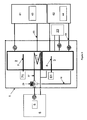
La
figure 1 représente un schéma de principe d'un mode de réalisation du dispositif selon l'invention et plus particulièrement du ballon 1 et de ses liaisons avec les composants associés : pompe à chaleur 5, circuit de chauffage et/ou climatisation 22,Thefigure 1 represents a block diagram of an embodiment of the device according to the invention and more particularly the balloon 1 and its connections with the associated components:heat pump 5, heating circuit and / orair conditioning 22, -
La
figure 2 représente un schéma de principe d'un mode de réalisation du dispositif selon l'invention et plus particulièrement du ballon 1 et de ses liaisons avec les composants associés : pompe à chaleur 5, circuit de chauffage et/ou climatisation 22, 36, panneau solaire thermique 9, chaudière 12, piscine 14, appareils de climatisation supplémentaires 13.Thefigure 2 represents a block diagram of an embodiment of the device according to the invention and more particularly the balloon 1 and its connections with the associated components:heat pump 5, heating circuit and / orair conditioning swimming pool 14, additionalair conditioning units 13. -
La
figure 3 représente un schéma de principe d'un mode de réalisation du dispositif selon l'invention dans lequel des blocs de stockage de l'énergie 43, 44 sont placés dans des ballons supplémentaires 61, 62 raccordés respectivement avec le ballon d'eau chaude sanitaire 2 et le ballon de désaccouplage 3.Thefigure 3 represents a block diagram of an embodiment of the device according to the invention in whichenergy storage blocks additional balloons hot water tank 2 and theuncoupling balloon 3.
Dans le présent document, on entend par :
- Dispositif thermodynamique : Ensemble comportant un compresseur et plusieurs échangeurs de chaleur dans lesquels circule un fluide de transfert spécifique appelé usuellement fluide frigorigène. Dans le cadre de la présente invention, le dispositif thermodynamique est une pompe à chaleur.
- Echangeur de chaleur : Dispositif destiné à transférer de la chaleur entre plusieurs circuits.
- Fluide caloporteur ou fluide de transfert : Fluide utilisé pour transférer de la chaleur. Les exemples classiques sont le fluide frigorigène, l'eau ou l'eau glycolée parfois appelé saumure.
- Panneau solaire thermique ou capteur solaire thermique : Dispositif qui recueille l'énergie thermique provenant du soleil et la transmet à un fluide caloporteur.
- Source : Milieu d'où une pompe à chaleur extrait la chaleur en mode chauffage.
- Pompe à chaleur monobloc : Pompe à chaleur composée d'une unité unique, comprenant le compresseur et les échangeurs de chaleur (condenseur et évaporateur), placée à l'extérieur ou à l'intérieur du bâtiment.
- Pompe à chaleur « split » : Pompe à chaleur composée de deux unités séparées, l'une placée à l'extérieur du bâtiment et comprenant le compresseur et un premier échangeur de chaleur (évaporateur en mode chauffage) et l'autre placée à l'intérieur du bâtiment et comprenant un second échangeur de chaleur (condenseur en mode chauffage), les deux unités étant reliées par deux conduites dans lesquelles est transporté un fluide caloporteur.
- Pompe à chaleur basse température : Pompe à chaleur destinée à alimenter des appareils de chauffage fonctionnant à basse température, typiquement 27 à 45°C, et de préférence 27 à 35°C, tels qu'un plancher chauffant, des ventiloconvecteurs, des radiateurs basse température, i.e. des radiateurs permettant d'obtenir une température de confort en hiver avec une eau de chauffage de l'ordre de 45°C.
- Pompe à chaleur haute température : Pompe à chaleur destinée à alimenter des appareils de chauffage fonctionnant à haute température, typiquement 50 à 65°C, tels que des radiateurs.
- Thermodynamic device: An assembly comprising a compressor and a plurality of heat exchangers in which circulates a specific transfer fluid usually called a refrigerant. In the context of the present invention, the thermodynamic device is a heat pump.
- Heat exchanger: Device intended to transfer heat between several circuits.
- Heat transfer fluid or transfer fluid: Fluid used to transfer heat. Typical examples are refrigerant, water or brine sometimes called brine.
- Thermal solar panel or solar thermal collector: Device that collects heat energy from the sun and transmits it to a heat transfer fluid.
- Source: Environment where a heat pump extracts heat in heating mode.
- Monobloc heat pump: A heat pump consisting of a single unit, including the compressor and the heat exchangers (condenser and evaporator), placed outside or inside the building.
- Split heat pump: A heat pump consisting of two separate units, one located outside the building and including the compressor and a first heat exchanger (evaporator heating mode) and the other placed inside the building and comprising a second heat exchanger (condenser heating mode), the two units being connected by two pipes in which is transported a heat transfer fluid .
- Low temperature heat pump: A heat pump intended to supply heating appliances operating at low temperature, typically 27 to 45 ° C, and preferably 27 to 35 ° C, such as underfloor heating, fan convectors, low radiators temperature, ie radiators to obtain a comfort temperature in winter with a heating water of the order of 45 ° C.
- High temperature heat pump: A heat pump intended to supply heating appliances operating at high temperature, typically 50 to 65 ° C, such as radiators.
Comme mentionné précédemment, le problème que la présente invention se propose de résoudre est de fournir un dispositif, comprenant un ballon monobloc muni de deux réservoirs, et permettant le chauffage d'eau (telle que de l'eau chaude sanitaire) et, séparément et indépendamment, le chauffage ou le refroidissement d'eau ou d'un autre liquide caloporteur, pour le chauffage et la climatisation, et ledit ballon permettant également le stockage simultané d'eau chaude (telle que de l'eau chaude sanitaire) et d'un liquide caloporteur tiède ou froid (tel que de l'eau pour le chauffage ou la climatisation de locaux), avec un encombrement réduit par rapport à celui des dispositifs existants dans l'état de la technique.As mentioned above, the problem that the present invention proposes to solve is to provide a device, comprising a one-piece balloon provided with two tanks, and allowing the heating of water (such as domestic hot water) and, separately and independently, the heating or cooling of water or other coolant, for heating and cooling, and said balloon also allowing simultaneous storage of hot water (such as domestic hot water) and a lukewarm or cold heat transfer liquid (such as water for space heating or cooling), with a smaller footprint compared to that of existing devices in the state of the art.
Selon l'invention, le problème est résolu par un dispositif combiné de production d'eau à deux températures T1 et T2 différentes, comprenant une pompe à chaleur 5 et un ballon 1 fractionné en deux parties 2, 3, dans lequel les deux parties 2, 3 dudit ballon 1 forment, pour la partie 2 un ballon d'eau chaude sanitaire, et pour la partie 3 un ballon dit « ballon de désaccouplage ». Les deux parties 2, 3 du ballon 1 sont isolées thermiquement et hydrauliquement l'une de l'autre. Dans la suite du texte, on fait généralement référence à la partie 2 du ballon 1 en utilisant l'expression « ballon d'eau chaude sanitaire 2 », et à la partie 3 du ballon 1 en utilisant l'expression « ballon de désaccouplage 3 ».According to the invention, the problem is solved by a combined device for producing water at two different temperatures T1 and T2, comprising a
Le ballon d'eau chaude sanitaire 2 contient un échangeur de chaleur 8. L'échangeur de chaleur 8 du ballon d'eau chaude sanitaire 2 et le ballon de désaccouplage 3 peuvent échanger tous les deux de la chaleur avec le condenseur (en mode chauffage) ou l'évaporateur (en mode climatisation) de la pompe à chaleur 5, à travers une vanne trois voies 29.The domestic
Un tel dispositif est représenté schématiquement sur la
Le ballon de la présente invention est fractionné en deux parties :
- (i) Un premier ballon dit ballon d'eau chaude sanitaire 2, préférentiellement en acier inoxydable ou en acier émaillé ou thermolaqué, ou en acier revêtu d'une peinture époxy, doté d'un échangeur de chaleur 8 relié à la pompe à chaleur 5 par
un circuit hydraulique 37, et pourvu en outre d'une résistance électrique chauffante 7, qui fonctionne de manière intermittente pour porter l'eau stockée dans le ballon 2 à une température supérieure à 70°C afin de détruire les micro-organismes du genre Legionella, et notamment de type Legionella pneumophilia, - (ii) Un second ballon dit ballon de désaccouplage 3, préférentiellement en acier, destiné à contenir un fluide caloporteur chaud ou froid destiné au chauffage ou à la climatisation de bâtiments, et relié à la pompe à chaleur 5 par
un circuit hydraulique 18.
- (i) A first balloon called sanitary
hot water cylinder 2, preferably made of stainless steel or enamelled or powder coated steel, or steel coated with an epoxy paint, equipped with aheat exchanger 8 connected to theheat pump 5 by ahydraulic circuit 37, and further provided with anelectric heating resistor 7, which operates intermittently to bring the water stored in thetank 2 to a temperature above 70 ° C to destroy the microorganisms of the genus Legionella , and in particular of the Legionella pneumophilia type, - (ii) A second balloon said
uncoupling balloon 3, preferably steel, intended to contain a hot or cold heat transfer fluid for heating or cooling buildings, and connected to theheat pump 5 by ahydraulic circuit 18.
Pour une utilisation en climatisation, l'eau ou un autre fluide caloporteur froid a, en fonction de l'usage prévu, une température T2 comprise entre environ 6°C et 12°C pour l'usage direct en climatisation, et entre environ 15 et 18°C pour l'usage dans un plancher chauffant fonctionnant en mode rafraîchissant.For use in air conditioning, the water or other cold heat transfer fluid has, according to the intended use, a temperature T2 of between about 6 ° C and 12 ° C for direct use in air conditioning, and between about 15 and 18 ° C for use in a heated floor operating in cooling mode.
Pour une utilisation en mode chauffage, le fluide caloporteur du ballon de désaccouplage 3 a, selon l'usage prévu, une température T2 comprise entre 27 et 45°C, de préférence 35°C pour une utilisation en plancher chauffant ou avec des ventiloconvecteurs ou des radiateurs basse température, et une température T2 comprise entre 45°C et 65 °C pour une utilisation avec des radiateurs classiques. Le plus souvent et de manière préférée, T2 est inférieure à T1.For use in heating mode, the coolant of the
Le ballon d'eau chaude sanitaire 2 et le ballon de désaccouplage 3 sont en outre isolés thermiquement l'un de l'autre. Cette isolation thermique permet le stockage simultané d'eau chaude sanitaire à une température T1 comprise entre 50°C et 70°C dans le ballon 2 et d'un fluide caloporteur froid à une température T2 comprise entre 6°C et 18°C destinée à la climatisation dans le ballon de désaccouplage 3 sans échange thermique entre le ballon d'eau chaude sanitaire 2 et le ballon de désaccouplage 3.The domestic
De plus, le ballon d'eau chaude sanitaire 2 et le ballon de désaccouplage 3 ne sont pas en contact hydraulique l'un avec l'autre, l'un étant destiné à contenir de l'eau à usage domestique, et l'autre un fluide caloporteur qui peut être de l'eau, mais également de l'eau glycolée, ou un autre fluide caloporteur antigel par exemple, et destiné en particulier au chauffage et/ou à la climatisation de bâtiments.In addition, the domestic
Dans le ballon d'eau chaude sanitaire 2, l'eau chaude sanitaire à usage domestique est stockée. Un échangeur de chaleur 8, par exemple un serpentin, relié à la pompe à chaleur 5 par un circuit hydraulique 37 et placé dans le ballon d'eau chaude sanitaire 2, permet un échange de chaleur avec la pompe à chaleur 5 afin de chauffer l'eau chaude sanitaire, par circulation d'un liquide caloporteur qui prend de la chaleur au condenseur (non représenté) de la pompe à chaleur.In domestic
Le ballon de désaccouplage 3 est relié à la pompe à chaleur 5 par un circuit hydraulique 18 dans lequel circule un fluide caloporteur. Le ballon de désaccouplage 3 est d'autre part relié aux dispositifs de chauffage et/ou de climatisation 13, 22, 36 par des circuits hydrauliques 21, 33, 38, dans lesquels circule également le fluide caloporteur.The
Dans le ballon de désaccouplage 3, le fluide caloporteur, tel que de l'eau ou de l'eau glycolée, peut être stocké. Le ballon de désaccouplage 3 a en particulier un rôle de tampon pour éviter les courts cycles du compresseur de la pompe à chaleur. Ce type de ballons, ou bouteilles, est communément utilisé dans les circuits hydrauliques de chauffage/climatisation dans les cas où le volume de liquide dans les circuits est faible. Le ballon de désaccouplage 3 a également pour fonction de mélanger le fluide caloporteur des circuits hydrauliques 21, 33, 38 des appareils de chauffage/refroidissement des bâtiments 22, 36, 13 avec le fluide caloporteur chauffé ou refroidi par la pompe à chaleur 5.In the
La pompe à chaleur 5 du dispositif selon l'invention peut être de tout type connu permettant le chauffage et/ou le refroidissement de bâtiments par un liquide caloporteur. Il peut s'agir par exemple d'une pompe à chaleur de type monobloc ou split, air/eau ou géothermie/eau.The
Dans le cas où la pompe à chaleur est de type air/eau, les sources de chaleur peuvent être l'air extérieur et/ou l'air extrait de ventilation et/ou un mélange d'air extérieur et d'air extrait de ventilation.In the case where the heat pump is of the air / water type, the heat sources may be outside air and / or extract air from ventilation and / or a mixture of outside air and extract air from ventilation. .
Les pompe à chaleur de type géothermie/eau peuvent être des pompes à chaleur de type sol/eau, c'est-à-dire des pompes à chaleur utilisant comme source ou capteur une boucle de réfrigérant passant dans le sol extérieur. Les pompes à chaleur de type géothermie/eau peuvent également être de type eau glycolée/eau, c'est-à-dire des pompes à chaleur utilisant comme source ou capteur une boucle d'eau glycolée passant dans le sol extérieur. Enfin, les pompes à chaleur de type géothermie/eau peuvent également être de type eau/eau, c'est-à-dire des pompes à chaleur utilisant comme source ou capteur une boucle « ouverte » sur l'eau d'une nappe phréatique ou d'une rivière.The geothermal / water type heat pumps may be ground / water type heat pumps, ie heat pumps using as a source or sensor a loop of refrigerant passing into the external ground. The geothermal / water type heat pumps can also be of the brine / water type, that is to say heat pumps using as a source or sensor a brine loop passing into the external ground. Finally, the geothermal / water type heat pumps can also be water / water type, that is to say heat pumps using as source or sensor an "open" loop on the water of a water table or a river.
Dans un mode de réalisation, la pompe à chaleur 5 du dispositif selon l'invention est une pompe à chaleur basse température, et au moins un des appareils de chauffage/climatisation associés 22, 36 est un plancher chauffant, éventuellement rafraîchissant, ou un ventiloconvecteur, ou radiateur basse température. Dans ce mode de réalisation, la pompe à chaleur 5 basse température chauffe le fluide caloporteur du ballon de désaccouplage 3 à une température T2 avantageusement comprise entre 27°C et 45°C, de préférence 35°C.In one embodiment, the
Dans un autre mode de réalisation, la pompe à chaleur 5 du dispositif selon l'invention est une pompe à chaleur haute température et les appareils de chauffage/climatisation associés 22, 36 sont des radiateurs ou des convecteurs. Dans ce mode de réalisation, la pompe à chaleur haute température chauffe le fluide caloporteur du ballon de désaccouplage 3 à une température T2 avantageusement comprise entre 50°C et 65°C.In another embodiment, the
Dans encore un autre mode de réalisation, le dispositif selon l'invention est doté d'au moins deux appareils de chauffage/climatisation 22, 36, placés dans deux zones différentes d'un bâtiment, et fonctionnant avec des températures de fluide caloporteur éventuellement différentes. La température de chacune des zones est régulée par les dispositifs de régulation de température 19, 20. Ces dispositifs commandent l'actionnement des circulateurs (ou pompes) 25, 26.In yet another embodiment, the device according to the invention is provided with at least two heating /
En outre, dans le dispositif selon l'invention, l'énergie calorifique nécessaire au chauffage de l'eau chaude sanitaire est fournie par le condenseur (non représenté sur les dessins) de la pompe à chaleur 5. Cela permet de disposer d'une puissance calorifique élevée pour le chauffage de l'eau chaude sanitaire, contrairement à certains dispositifs de l'état de la technique. Le chauffage de l'eau chaude sanitaire est réalisé par échange de chaleur avec du liquide caloporteur grâce à l'échangeur de chaleur 8, et non pas par échange de chaleur avec du fluide réfrigérant comme dans d'autres dispositifs de l'état de la technique. En effet, la réglementation en vigueur en Europe interdit l'utilisation d'échangeur de chaleur contenant du fluide réfrigérant dans les ballons d'eau destinée à un usage domestique ou sanitaire.In addition, in the device according to the invention, the heat energy required for heating the domestic hot water is supplied by the condenser (not shown in the drawings) of the
D'autre part, le ballon mixte 1 permet de stocker simultanément de l'eau et du fluide caloporteur à deux températures respectives T1 et T2 différentes. Ceci est rendu possible par une isolation thermique entre le ballon d'eau chaude sanitaire 2 et le ballon de désaccouplage 3, obtenue par exemple en plaçant entre les deux ballons une quantité suffisant d'un isolant thermique efficace tel que de la mousse de polyuréthane, de la laine de verre, de la laine de roche, du polystyrène expansé. Un isolant non polluant pour l'environnement ou naturel, tel que de la laine de mouton ou de chanvre peut avantageusement être utilisé.On the other hand, the mixed balloon 1 makes it possible to simultaneously store water and heat transfer fluid at two different temperatures T1 and T2, respectively. This is made possible by thermal insulation between the domestic
Une résistance électrique 6 peut être placée sur le circuit de fluide caloporteur, soit dans la pompe à chaleur 5, tel que représenté sur la
Une vanne trois voies 29 placée dans le circuit du fluide caloporteur en sortie de la pompe à chaleur 5 permet d'envoyer ledit fluide caloporteur soit vers l'échangeur de chaleur 8 du ballon d'eau chaude sanitaire 2 soit vers le ballon de désaccouplage 3 selon les besoins.A three-
Dans un mode de réalisation particulier, la pompe à chaleur 5 est une pompe à chaleur réversible, capable, en fonction des besoins, de chauffer ou de refroidir un fluide caloporteur tel que de l'eau, grâce à une inversion de son cycle thermodynamique (le condenseur devient l'évaporateur et réciproquement). Lorsque des besoins de climatisation existent, la pompe à chaleur refroidit le fluide caloporteur du ballon de désaccouplage 3. Quand des besoins en eau chaude sanitaire apparaissent, un module de commande inverse le fonctionnement de la pompe à chaleur 5, qui chauffe alors le fluide caloporteur, qui est envoyé dans l'échangeur 8 du ballon d'eau chaude sanitaire 2, grâce à la vanne trois voies 29.In a particular embodiment, the
Dans un mode de réalisation particulier, le dispositif selon l'invention comprend en outre un panneau solaire thermique 9. Un échangeur de chaleur 10, par exemple un serpentin, relié au panneau solaire thermique 9 par un circuit hydraulique, et placé dans le ballon d'eau chaude sanitaire 2, permet de chauffer l'eau du ballon d'eau chaude sanitaire 2. Un autre échangeur de chaleur 11 relié au panneau solaire thermique par un circuit hydraulique et placé dans le ballon de désaccouplage 3 permet de chauffer l'eau du ballon de désaccouplage 3.In a particular embodiment, the device according to the invention further comprises a solar
Une vanne trois voies 32 placée dans le circuit du fluide caloporteur du panneau solaire thermique 9 permet d'envoyer le fluide caloporteur soit vers l'échangeur de chaleur 10 du ballon d'eau chaude sanitaire 2 soit vers l'échangeur de chaleur 11 du ballon de désaccouplage 3 selon les besoins.A three-
Dans encore un autre mode de réalisation particulier, une chaudière 12 est utilisé comme moyen de chauffage supplémentaire de l'eau du ballon de désaccouplage 3. La chaudière 12 peut être une chaudière à bois, gaz, fioul, résistances électriques, ou une cheminée dotée d'un système d'extraction de l'air chaud. La chaudière 12 peut avoir un intérêt lorsque la puissance de la pompe à chaleur est limitée, par exemple dans le cas d'une pompe à chaleur air/eau lorsque les températures extérieures sont très basses.In yet another particular embodiment, a boiler 12 is used as an additional means of heating the water of the
Dans un autre mode de réalisation particulier, le ballon de désaccouplage 3 comprend en outre un échangeur de chaleur 15 destiné à chauffer ou refroidir l'eau d'une piscine 14. Ce mode de réalisation permet aussi d'écouler une éventuelle surproduction d'eau chaude par le panneau solaire thermique 9, en chauffant une piscine 14 agissant dans ce cas comme puits de chaleur de capacité quasi-infinie. L'utilisation du panneau solaire thermique pour le chauffage de l'eau d'une piscine permet en outre de disposer d'une énergie thermique gratuite et renouvelable.In another particular embodiment, the
En outre, le dispositif selon l'invention est pourvu d'un boîtier ou module de commande électronique (non représenté). Ce boîtier permet de commander les différents composants du dispositif tels que les vannes trois voies 29, 30, 31, 32, le démarrage ou l'arrêt du compresseur (non représenté) de la pompe à chaleur 5 en fonction des besoins de chauffage de l'eau chaude sanitaire et/ou de chauffage et de refroidissement du fluide caloporteur contenu dans le ballon de désaccouplage 3. Le boîtier de commande est programmé de manière à tenir compte en particulier, mais de manière non limitative, de la température extérieure mesurée par la sonde extérieure 17 et de la loi d'eau de la pompe à chaleur 5. On entend par « loi d'eau » une fonction de régulation qui permet de contrôler la température de l'eau de chauffage en fonction de la température extérieure.In addition, the device according to the invention is provided with a housing or electronic control module (not shown). This housing makes it possible to control the various components of the device such as the three-
Dans un autre mode de réalisation particulier, le dispositif selon l'invention comprend en outre des blocs de stockage de l'énergie calorifique 41, 42, 43, 44. Ces blocs de stockage de l'énergie peuvent être constitués par exemple de matériaux composites graphite/paraffine, ou comportent de tels matériaux composites ; ces matériaux composites font partie de l'état de la technique. Dans ce cas, il s'agit d'un stockage principalement par chaleur latente.In another particular embodiment, the device according to the invention further comprises storage blocks of the
Les blocs de stockage de l'énergie calorifique 41, 42, 43, 44 peuvent être placés dans le ballon d'eau chaude sanitaire 2 et/ou dans le ballon de désaccouplage 3 et/ou dans un ou plusieurs conteneurs situés à l'extérieur d'au moins un de ces ballons 2, 3 et peuvent permettre de stocker de la chaleur, lors d'une surproduction par exemple, ou lorsque l'utilisateur bénéficie d'un tarif plus bas à certaines heures (« heures creuses ») pour l'électricité, et de restituer ensuite cette chaleur pour le chauffage de l'eau chaude sanitaire du ballon 2 et/ou le chauffage ou le refroidissement du fluide caloporteur du ballon de désaccouplage 3.The heat energy storage blocks 41, 42, 43, 44 may be placed in the domestic
Dans un mode de réalisation particulier, les blocs de stockage de l'énergie calorifique 43, 44 sont placés dans des ballons supplémentaires 61, 62, tel que représenté par la
Un premier avantage du dispositif selon l'invention est sa simplicité : en mode chauffage il ne possède qu'un seul condenseur.A first advantage of the device according to the invention is its simplicity: in heating mode it has only one condenser.
Un autre avantage du dispositif selon l'invention par rapport à ceux de l'état de la technique est qu'il possède à la fois une capacité de production d'eau chaude élevée, et une grande souplesse de fonctionnement.Another advantage of the device according to the invention compared to those of the state of the art is that it has both a high hot water production capacity, and great flexibility of operation.
En effet, dans le dispositif selon l'invention, l'énergie calorifique nécessaire au chauffage de l'eau chaude sanitaire est fournie par le condenseur (non représenté) de la pompe à chaleur 5. Cela permet d'avoir une puissance calorifique élevée. D'autre part, le ballon mixte 1, composé de deux parties 2, 3 isolées thermiquement l'une de l'autre, permet de stocker simultanément de l'eau et du fluide caloporteur à deux températures différentes.Indeed, in the device according to the invention, the heat energy required for heating the domestic hot water is provided by the condenser (not shown) of the
Le dispositif selon l'invention possède ainsi une grande souplesse de fonctionnement. En effet, le dispositif selon l'invention peut, simultanément, utiliser l'eau chaude sanitaire du ballon 2 en fonction des besoins des utilisateurs, et chauffer ou refroidir un espace d'un bâtiment en utilisant le fluide caloporteur contenu dans le ballon de désaccouplage 3. Dans le même temps, la pompe à chaleur 5 est utilisée soit pour chauffer l'eau chaude sanitaire, soit pour chauffer ou refroidir le fluide caloporteur du ballon de désaccouplage 3.The device according to the invention thus has a great flexibility of operation. Indeed, the device according to the invention can, simultaneously, use the domestic hot water of the
Ainsi, le dispositif selon l'invention peut être doté d'un système de régulation qui lui permet de fournir ou stocker de l'eau à une température T1 comprise entre 50°C et 70°C, et de l'eau à une température T2 qui peut être choisie par l'utilisateur en fonction de ses besoins parmi l'une quelconque des trois plages suivantes : T2 = 6°C à 18°C, T2 = 27°C à 45°C, de préférence 27°C à 35°C, T2 = 50°C à 65°C.Thus, the device according to the invention can be provided with a regulation system which enables it to supply or store water at a temperature T1 of between 50 ° C. and 70 ° C., and water at a temperature T2 which can be selected by the user according to his needs from any one of the following three ranges: T2 = 6 ° C to 18 ° C, T2 = 27 ° C to 45 ° C, preferably 27 ° C to 35 ° C, T2 = 50 ° C to 65 ° C.
Le dispositif selon l'invention peut être installé par exemple en remplacement d'une chaudière à gaz ou fioul avec ballon de stockage de l'eau chaude sanitaire, ce qui permet la réalisation d'économies d'énergie, ceci sans augmenter de façon substantielle l'encombrement intérieur total utilisé par le système de chauffage et de production d'eau chaude sanitaire.The device according to the invention can be installed for example in replacement of a gas or oil boiler with storage tank of domestic hot water, which allows the realization of energy savings, this without substantially increasing the total internal space used by the heating and hot water system.
Le ballon mixte 1 utilisé dans le dispositif selon l'invention peut facilement, moyennant quelques aménagements qui ne le font pas sortir du cadre de la présente invention, être relié à une pompe à chaleur classique, telle qu'une pompe monobloc air/eau ou air/air, ou une pompe à chaleur split avec un module hydraulique relié à l'unité intérieure. Par conséquent, le dispositif selon l'invention peut être obtenu en remplaçant le dispositif de production d'eau chaude sanitaire existant (et en particulier un cumulus électrique) d'un logement équipé par ailleurs d'une pompe à chaleur, par le ballon mixte 1 du dispositif selon l'invention, permettant là aussi une économie substantielle d'énergie.The mixed balloon 1 used in the device according to the invention can easily, with some adjustments that do not depart from the scope of the present invention, be connected to a conventional heat pump, such as a monobloc pump air / water or air / air, or a split heat pump with a hydraulic module connected to the unit interior. Therefore, the device according to the invention can be obtained by replacing the existing domestic hot water production device (and in particular an electric cumulus) of a housing also equipped with a heat pump, by the mixed balloon. 1 of the device according to the invention, also allowing a substantial saving of energy.
Claims (15)
ledit dispositif étant caractérisé en ce que l'échangeur (8) du ballon d'eau chaude sanitaire (2) et le ballon de désaccouplage (3) peuvent échanger tous les deux de la chaleur avec le condenseur (en mode chauffage) ou l'évaporateur (en mode climatisation) de la pompe à chaleur (5), à travers une vanne trois voies (29).Combined device for producing water at at least two different temperatures T1 and T2, comprising a heat pump (5) and a balloon (1) divided into two parts, said heat pump comprising a condenser and an evaporator, and said balloon comprising:
said device being characterized in that the exchanger (8) of the hot water tank (2) and the uncoupling tank (3) can both exchange heat with the condenser (in heating mode) or evaporator (in cooling mode) of the heat pump (5), through a three-way valve (29).
Applications Claiming Priority (1)
| Application Number | Priority Date | Filing Date | Title |
|---|---|---|---|
| FR0806981A FR2939874B1 (en) | 2008-12-12 | 2008-12-12 | THERMODYNAMIC DEVICE WITH MULTI-ENERGY HOT WATER BALLOON MULIT-SOURCES |
Publications (2)
| Publication Number | Publication Date |
|---|---|
| EP2196743A2 true EP2196743A2 (en) | 2010-06-16 |
| EP2196743A3 EP2196743A3 (en) | 2016-05-18 |
Family
ID=40912052
Family Applications (1)
| Application Number | Title | Priority Date | Filing Date |
|---|---|---|---|
| EP09015361.0A Withdrawn EP2196743A3 (en) | 2008-12-12 | 2009-12-11 | Multi-energy and multi-source thermodynamic device with hot water tank |
Country Status (2)
| Country | Link |
|---|---|
| EP (1) | EP2196743A3 (en) |
| FR (1) | FR2939874B1 (en) |
Cited By (6)
| Publication number | Priority date | Publication date | Assignee | Title |
|---|---|---|---|---|
| CN107062465A (en) * | 2017-01-16 | 2017-08-18 | 吴焕雄 | It is a kind of that there is production clean water, the combined system of air conditioning function |
| ITUA20164324A1 (en) * | 2016-06-13 | 2017-12-13 | Adsum S R L | PLUG & PLAY CENTRAL TO GENERATE DOMESTIC HOT WATER AND ITS CONTROL METHOD |
| CN110030612A (en) * | 2019-04-18 | 2019-07-19 | 太原向明智能装备股份有限公司 | One kind is provided multiple forms of energy to complement each other mine heating network system |
| CN110186103A (en) * | 2019-07-03 | 2019-08-30 | 天津理工大学 | A kind of compound energy heating system and method |
| CN114877508A (en) * | 2022-06-01 | 2022-08-09 | 国家电投集团东北电力有限公司大连大发能源分公司 | Renewable energy driven room temperature adjusting system |
| EP4293307A1 (en) * | 2022-06-16 | 2023-12-20 | Cordivari S.r.l. | Compact storage and heat exchange system for thermal systems, relative plant and method |
Citations (7)
| Publication number | Priority date | Publication date | Assignee | Title |
|---|---|---|---|---|
| US4037650A (en) | 1975-05-23 | 1977-07-26 | National Research Development Corporation | Thermal storage apparatus |
| US4350200A (en) | 1978-07-24 | 1982-09-21 | Mcelwain John A | Solar energy collector and system |
| US4524909A (en) | 1982-11-15 | 1985-06-25 | Ingemar Persson | Apparatus for production of hot tap water |
| EP0240441A2 (en) | 1986-03-27 | 1987-10-07 | Phenix Heat Pump Systems, Inc. | Three function heat pump system and method |
| DE19815521A1 (en) | 1998-04-07 | 1999-10-14 | Dieter Weinhold | Heat recovery system for building heating |
| WO2006101404A2 (en) | 2005-03-23 | 2006-09-28 | Kjell Emil Eriksen | A system for utilization of thermal energy |
| FR2905750A1 (en) | 2006-09-13 | 2008-03-14 | Jean Bernard Hurier | COMBINED BOILER / SANITARY WATER HEATER. |
Family Cites Families (11)
| Publication number | Priority date | Publication date | Assignee | Title |
|---|---|---|---|---|
| US3207358A (en) * | 1961-07-27 | 1965-09-21 | Gen Electric | Water storage tanks and methods of making the same |
| US4380156A (en) * | 1979-06-04 | 1983-04-19 | Atlantic Richfield Company | Multiple source heat pump |
| DK348279A (en) * | 1979-08-21 | 1981-02-22 | Genvex Energiteknik | HEAT EXCHANGE |
| US4308042A (en) * | 1980-04-11 | 1981-12-29 | Atlantic Richfield Company | Heat pump with freeze-up prevention |
| DE3044684A1 (en) * | 1980-11-27 | 1982-07-08 | Günter 2370 Rendsburg Braun | Solar heat recovery system - incorporates heat pump in two stages connected by coupling storage unit |
| DE3227925A1 (en) * | 1981-07-29 | 1983-02-17 | Alfa-Laval Stalltechnik GmbH, 1120 Wien | Heating plant |
| DE3535752A1 (en) * | 1985-10-07 | 1987-04-09 | Siebel Achenbach & Braun Behae | Pressure vessel |
| CN1247944C (en) * | 2003-12-17 | 2006-03-29 | 华南理工大学 | Heat reservoir of heat storage type heat pump air conditioning device and preparation method of heat storage material of heat reservoir |
| NO326274B1 (en) * | 2005-03-23 | 2008-10-27 | Kjell Emil Eriksen | Energy utilization system and method |
| US7923112B2 (en) * | 2005-05-12 | 2011-04-12 | Sgl Carbon Se | Latent heat storage material and process for manufacture of the latent heat storage material |
| FR2899671B1 (en) * | 2006-04-11 | 2015-03-06 | Michel Louis Dupraz | HEATING SYSTEM, REFRIGERATION AND PRODUCTION OF SANITARY HOT WATER BY SOLAR SENSOR COMBINED WITH A HEAT PUMP AND A THERMAL RESERVE AT LOW TEMPERATURE. |
-
2008
- 2008-12-12 FR FR0806981A patent/FR2939874B1/en not_active Expired - Fee Related
-
2009
- 2009-12-11 EP EP09015361.0A patent/EP2196743A3/en not_active Withdrawn
Patent Citations (7)
| Publication number | Priority date | Publication date | Assignee | Title |
|---|---|---|---|---|
| US4037650A (en) | 1975-05-23 | 1977-07-26 | National Research Development Corporation | Thermal storage apparatus |
| US4350200A (en) | 1978-07-24 | 1982-09-21 | Mcelwain John A | Solar energy collector and system |
| US4524909A (en) | 1982-11-15 | 1985-06-25 | Ingemar Persson | Apparatus for production of hot tap water |
| EP0240441A2 (en) | 1986-03-27 | 1987-10-07 | Phenix Heat Pump Systems, Inc. | Three function heat pump system and method |
| DE19815521A1 (en) | 1998-04-07 | 1999-10-14 | Dieter Weinhold | Heat recovery system for building heating |
| WO2006101404A2 (en) | 2005-03-23 | 2006-09-28 | Kjell Emil Eriksen | A system for utilization of thermal energy |
| FR2905750A1 (en) | 2006-09-13 | 2008-03-14 | Jean Bernard Hurier | COMBINED BOILER / SANITARY WATER HEATER. |
Cited By (8)
| Publication number | Priority date | Publication date | Assignee | Title |
|---|---|---|---|---|
| ITUA20164324A1 (en) * | 2016-06-13 | 2017-12-13 | Adsum S R L | PLUG & PLAY CENTRAL TO GENERATE DOMESTIC HOT WATER AND ITS CONTROL METHOD |
| CN107062465A (en) * | 2017-01-16 | 2017-08-18 | 吴焕雄 | It is a kind of that there is production clean water, the combined system of air conditioning function |
| CN110030612A (en) * | 2019-04-18 | 2019-07-19 | 太原向明智能装备股份有限公司 | One kind is provided multiple forms of energy to complement each other mine heating network system |
| CN110186103A (en) * | 2019-07-03 | 2019-08-30 | 天津理工大学 | A kind of compound energy heating system and method |
| CN110186103B (en) * | 2019-07-03 | 2024-01-30 | 天津理工大学 | Composite energy heat supply system and method |
| CN114877508A (en) * | 2022-06-01 | 2022-08-09 | 国家电投集团东北电力有限公司大连大发能源分公司 | Renewable energy driven room temperature adjusting system |
| CN114877508B (en) * | 2022-06-01 | 2023-09-01 | 国家电投集团东北电力有限公司大连大发能源分公司 | Renewable energy driven room temperature regulating system |
| EP4293307A1 (en) * | 2022-06-16 | 2023-12-20 | Cordivari S.r.l. | Compact storage and heat exchange system for thermal systems, relative plant and method |
Also Published As
| Publication number | Publication date |
|---|---|
| EP2196743A3 (en) | 2016-05-18 |
| FR2939874B1 (en) | 2010-12-31 |
| FR2939874A1 (en) | 2010-06-18 |
Similar Documents
| Publication | Publication Date | Title |
|---|---|---|
| US7827814B2 (en) | Geothermal water heater | |
| RU2710632C2 (en) | District heat distribution system | |
| US9657998B2 (en) | Method for operating an arrangement for storing thermal energy | |
| EP2196743A2 (en) | Multi-energy and multi-source thermodynamic device with hot water tank | |
| CN108603668B (en) | Thermal management device and method of controlling a thermal management device | |
| EP1978311A2 (en) | System solar heating autonomous and independent of another energy source | |
| EP2592358A1 (en) | Facility for temperature control and hot-water production and method for implementing such a facility | |
| US10883728B2 (en) | Broad band district heating and cooling system | |
| WO2009071765A2 (en) | Heating/air-conditioning plant with heat pump, comprising a heat transfer fluid splitter box with coupling to a plurality of heat collecting and distributing circuits | |
| EP2856041B1 (en) | Facility for transforming heat energy | |
| FR2995979A1 (en) | INSTALLATION OF HEATING WATER HEATER WITH HEATING FUNCTION | |
| FR2938900A1 (en) | Air conditioning device for use in e.g. house, has circuit whose secondary heat exchanger is controlled and arranged in downstream of section and exchanging heat between air and exchanging medium formed by solar sensor | |
| FR3022989A1 (en) | THERMODYNAMIC WATER HEATER | |
| EP2069696A2 (en) | Module usable for heat storage and transfer | |
| RU2412401C1 (en) | Heating system of domestic building | |
| FR2922001A1 (en) | Heating installation for producing e.g. domestic hot water, in building, has heat pump collecting heat from fluid in exchanger and transferring heat to fluid in another exchanger, and third exchanger transferring heat to domestic hot water | |
| WO2013014178A1 (en) | Device for storing renewable energy in the form of heat and method for regeneration by trigeneration | |
| FR2906603A1 (en) | Heat storage and transfer module for e.g. ship, has high, medium and low temperature heat storage and exchange blocks, anti-return valves allowing passage of gas in one direction, and valve allowing operation in heating and cooling modes | |
| FR2954816A1 (en) | SOLAR CENTRAL HEATING DEVICE HAVING ENERGY ACCUMULATION | |
| EP3152510B1 (en) | Facility for converting heat into mechanical energy with optimised cooling by a system for recovering and storing a portion of the heat energy of the working fluid | |
| KR101545270B1 (en) | Collecting device heating and solar water heater | |
| FR2912809A1 (en) | Solar heating system for e.g. industrial building, has tanks supplied with solar energy, where system uses coolant presenting high ebullition temperature, low volatility, low kinematic viscosity coefficient and low expansion coefficient | |
| BE1025410B1 (en) | HEATING INSTALLATION | |
| EP1865273A1 (en) | Heating process and heater based on the principle of friction of fluids | |
| Zubaira et al. | Performance and cost assessment of a solar HDH desalination system integrated with thermal storage: a case study |
Legal Events
| Date | Code | Title | Description |
|---|---|---|---|
| PUAI | Public reference made under article 153(3) epc to a published international application that has entered the european phase |
Free format text: ORIGINAL CODE: 0009012 |
|
| 17P | Request for examination filed |
Effective date: 20091214 |
|
| AK | Designated contracting states |
Kind code of ref document: A2 Designated state(s): AT BE BG CH CY CZ DE DK EE ES FI FR GB GR HR HU IE IS IT LI LT LU LV MC MK MT NL NO PL PT RO SE SI SK SM TR |
|
| AX | Request for extension of the european patent |
Extension state: AL BA RS |
|
| PUAL | Search report despatched |
Free format text: ORIGINAL CODE: 0009013 |
|
| AK | Designated contracting states |
Kind code of ref document: A3 Designated state(s): AT BE BG CH CY CZ DE DK EE ES FI FR GB GR HR HU IE IS IT LI LT LU LV MC MK MT NL NO PL PT RO SE SI SK SM TR |
|
| AX | Request for extension of the european patent |
Extension state: AL BA RS |
|
| RIC1 | Information provided on ipc code assigned before grant |
Ipc: F24H 4/04 20060101AFI20160408BHEP |
|
| STAA | Information on the status of an ep patent application or granted ep patent |
Free format text: STATUS: REQUEST FOR EXAMINATION WAS MADE |
|
| RAP1 | Party data changed (applicant data changed or rights of an application transferred) |
Owner name: COMECA POWER |
|
| STAA | Information on the status of an ep patent application or granted ep patent |
Free format text: STATUS: EXAMINATION IS IN PROGRESS |
|
| 17Q | First examination report despatched |
Effective date: 20191014 |
|
| STAA | Information on the status of an ep patent application or granted ep patent |
Free format text: STATUS: EXAMINATION IS IN PROGRESS |
|
| GRAP | Despatch of communication of intention to grant a patent |
Free format text: ORIGINAL CODE: EPIDOSNIGR1 |
|
| STAA | Information on the status of an ep patent application or granted ep patent |
Free format text: STATUS: GRANT OF PATENT IS INTENDED |
|
| INTG | Intention to grant announced |
Effective date: 20210721 |
|
| STAA | Information on the status of an ep patent application or granted ep patent |
Free format text: STATUS: THE APPLICATION IS DEEMED TO BE WITHDRAWN |
|
| 18D | Application deemed to be withdrawn |
Effective date: 20211201 |