EP2196960A1 - Device and method for accepting postal items - Google Patents
Device and method for accepting postal items Download PDFInfo
- Publication number
- EP2196960A1 EP2196960A1 EP09014936A EP09014936A EP2196960A1 EP 2196960 A1 EP2196960 A1 EP 2196960A1 EP 09014936 A EP09014936 A EP 09014936A EP 09014936 A EP09014936 A EP 09014936A EP 2196960 A1 EP2196960 A1 EP 2196960A1
- Authority
- EP
- European Patent Office
- Prior art keywords
- mail piece
- mailpiece
- piece
- user
- Prior art date
- Legal status (The legal status is an assumption and is not a legal conclusion. Google has not performed a legal analysis and makes no representation as to the accuracy of the status listed.)
- Granted
Links
- 238000000034 method Methods 0.000 title claims abstract description 21
- 238000003780 insertion Methods 0.000 claims abstract description 31
- 230000037431 insertion Effects 0.000 claims abstract description 31
- 238000003860 storage Methods 0.000 claims description 58
- 238000007639 printing Methods 0.000 claims description 29
- 238000012384 transportation and delivery Methods 0.000 claims description 16
- 238000004891 communication Methods 0.000 claims description 13
- 238000013475 authorization Methods 0.000 claims description 12
- 230000009471 action Effects 0.000 claims description 5
- 238000000151 deposition Methods 0.000 claims description 3
- 238000012795 verification Methods 0.000 claims description 3
- 230000005484 gravity Effects 0.000 claims description 2
- 238000007789 sealing Methods 0.000 claims description 2
- 238000012546 transfer Methods 0.000 claims description 2
- 230000032258 transport Effects 0.000 description 49
- 239000000370 acceptor Substances 0.000 description 15
- 238000012545 processing Methods 0.000 description 12
- 238000011156 evaluation Methods 0.000 description 6
- 239000002699 waste material Substances 0.000 description 6
- 241001136792 Alle Species 0.000 description 5
- 206010053648 Vascular occlusion Diseases 0.000 description 5
- 230000004888 barrier function Effects 0.000 description 5
- 230000008901 benefit Effects 0.000 description 5
- 230000008569 process Effects 0.000 description 5
- 239000003795 chemical substances by application Substances 0.000 description 4
- 230000001419 dependent effect Effects 0.000 description 4
- 238000013461 design Methods 0.000 description 4
- 238000000429 assembly Methods 0.000 description 3
- 230000000712 assembly Effects 0.000 description 3
- 238000009826 distribution Methods 0.000 description 3
- 230000006870 function Effects 0.000 description 3
- 238000005299 abrasion Methods 0.000 description 2
- 230000005540 biological transmission Effects 0.000 description 2
- 230000006378 damage Effects 0.000 description 2
- 238000005516 engineering process Methods 0.000 description 2
- 238000012423 maintenance Methods 0.000 description 2
- 239000003550 marker Substances 0.000 description 2
- 210000002023 somite Anatomy 0.000 description 2
- 230000003213 activating effect Effects 0.000 description 1
- 239000000853 adhesive Substances 0.000 description 1
- 239000000969 carrier Substances 0.000 description 1
- 230000008859 change Effects 0.000 description 1
- 238000012790 confirmation Methods 0.000 description 1
- 238000011161 development Methods 0.000 description 1
- 230000018109 developmental process Effects 0.000 description 1
- 230000002349 favourable effect Effects 0.000 description 1
- 230000007257 malfunction Effects 0.000 description 1
- 239000002184 metal Substances 0.000 description 1
- 238000012986 modification Methods 0.000 description 1
- 230000004048 modification Effects 0.000 description 1
- 238000011022 operating instruction Methods 0.000 description 1
- 230000003287 optical effect Effects 0.000 description 1
- 238000004806 packaging method and process Methods 0.000 description 1
- 238000012856 packing Methods 0.000 description 1
- 230000000149 penetrating effect Effects 0.000 description 1
- 230000001681 protective effect Effects 0.000 description 1
- 238000005070 sampling Methods 0.000 description 1
- 125000006850 spacer group Chemical group 0.000 description 1
- 238000011144 upstream manufacturing Methods 0.000 description 1
- 238000005303 weighing Methods 0.000 description 1
- 238000003466 welding Methods 0.000 description 1
Images


Classifications
-
- G—PHYSICS
- G07—CHECKING-DEVICES
- G07B—TICKET-ISSUING APPARATUS; FARE-REGISTERING APPARATUS; FRANKING APPARATUS
- G07B17/00—Franking apparatus
- G07B17/00185—Details internally of apparatus in a franking system, e.g. franking machine at customer or apparatus at post office
- G07B17/00193—Constructional details of apparatus in a franking system
-
- G—PHYSICS
- G07—CHECKING-DEVICES
- G07F—COIN-FREED OR LIKE APPARATUS
- G07F17/00—Coin-freed apparatus for hiring articles; Coin-freed facilities or services
- G07F17/10—Coin-freed apparatus for hiring articles; Coin-freed facilities or services for means for safe-keeping of property, left temporarily, e.g. by fastening the property
- G07F17/12—Coin-freed apparatus for hiring articles; Coin-freed facilities or services for means for safe-keeping of property, left temporarily, e.g. by fastening the property comprising lockable containers, e.g. for accepting clothes to be cleaned
- G07F17/13—Coin-freed apparatus for hiring articles; Coin-freed facilities or services for means for safe-keeping of property, left temporarily, e.g. by fastening the property comprising lockable containers, e.g. for accepting clothes to be cleaned the containers being a postal pick-up locker
-
- G—PHYSICS
- G07—CHECKING-DEVICES
- G07B—TICKET-ISSUING APPARATUS; FARE-REGISTERING APPARATUS; FRANKING APPARATUS
- G07B17/00—Franking apparatus
- G07B17/00185—Details internally of apparatus in a franking system, e.g. franking machine at customer or apparatus at post office
- G07B17/00193—Constructional details of apparatus in a franking system
- G07B2017/00225—Vending machine or POS (Point Of Sale) apparatus
-
- G—PHYSICS
- G07—CHECKING-DEVICES
- G07B—TICKET-ISSUING APPARATUS; FARE-REGISTERING APPARATUS; FRANKING APPARATUS
- G07B17/00—Franking apparatus
- G07B17/00459—Details relating to mailpieces in a franking system
- G07B17/00467—Transporting mailpieces
- G07B2017/00475—Sorting mailpieces
Definitions
- the invention relates to a device and a method for mail acceptance, according to the type specified in the preamble of claims 1 and 10 and is suitable for a mail processing machine, which is placed in the post office, in shops, gas stations and / or public places or private facilities and the mail piece acceptance is used.
- the mail distribution is prepared by a mail carrier after a franking of the mail, with each post office a printing of a receipt receipt for the postal customer and printing a machine-readable mark on the mail piece.
- an input of other relevant data is in the first memory of the loading station, which due to the marking, the aforementioned data can be stored assigned to the mail piece and retrieved again.
- the input can be done with the support of a customer-related chip card, which is plugged into a first read / write unit and for identifying the customer-related chip card or the customer is made.
- the retrieval of the data for example, also by means of the special first read / write unit by a carrier chip card is inserted, for loading the booking data from the first memory in a memory of the special carrier card. Then, a discharge of the storage container of the loading station and a transport of the marked mail and the special carrier card by a first mail carrier to a remote franking machine in a dispensing station. After inserting the special carrier card into a second read / write unit and loading the booking data from the memory of the special carrier card into a second memory of the postage meter, the mail is franked in the dispensing station in accordance with the data stored in the second memory associated with the tag information which is recovered from the scannable mark printed on the mail piece.
- a remote dispensing station includes a marker reader and a postage meter system.
- the latter preferably consists of an automatic feeder station, a dynamic weighing station and a franking station.
- the marker reading device can be integrated into the postage meter system.
- the mail processing system thus consists of a plurality of mailing stations and a plurality of mailing stations between which a (private) mail carrier operates to empty mail piece storage containers and convey mail pieces to the mail dispensing station which stamp the mailpieces.
- a (private) mail carrier operates to empty mail piece storage containers and convey mail pieces to the mail dispensing station which stamp the mailpieces.
- the mailing stations are simply constructed, the mailing stations must be more complex, ie, equipped with additional stations, such as a dynamic scale station.
- a mail delivery station can be constructed simply (without scales) if the mail delivery stations already have a scale, ie are more complexaded.
- a variety of design variants for a mail processing system is conceivable.
- the disadvantage is that, on the one hand, an overfilling of the mail piece acceptance device is possible and, on the other hand, an emptying of the mail piece acceptance devices in a fixed position Time intervals also takes place, if there was no postal item stored.
- stations with a scale are usually subject to verification, which causes increased maintenance costs.
- DPAG solves this problem through automation using the new Post24 / 7 machines in addition to the well-known mail acceptance points (formerly post offices) and mailboxes.
- the new Post24 / 7 machines are coupled with stamp dispensers and mailboxes. From the stamp donor, the postal customer must first pull stamps and stick on a piece of mail, which can then be thrown into a neighboring conventional mailbox from the postal customer.
- a packing station At the back of the Post24 / 7 machine is a packing station.
- An electric parcel compartment system and a method for its operation is known from the European patent EP 1408 802 B1 known to the DPAG.
- Registered customers can also have shipments sent to the Post24 / 7 station. You will then be notified by email / SMS and can pick up the shipment regardless of opening hours.
- the postal authorities of a majority of countries and private service providers are aware of a procedure that assumes that the delivered mail has been cleared by the customer.
- the service providers are faced with the task of reducing branch services or penetrating markets in which the service provider does not yet have any branches.
- the letter acceptance devices In order to completely replace branches, the letter acceptance devices must be calibrated as long as they detect a postage. However, if no postage is determined, this task is relocated to the mail centers to sort out postal items that have not or not been adequately cleared by the postal customer. The mode of operation of the letter reception centers is therefore to be seen in conjunction with that of the letter centers.
- Sorting in DPAG's mail center is carried out semi-automatically.
- the letter center are sorted according to an orientation and orientation of the mail pieces, the latter according to the types of mail categories: length, width, height and weight sorted.
- the DPAG transmission types are postcards, standard letters, compact letters, large letters and maxi letters.
- the programs are thrown into small compartments ( DE 10 2004 040 100 A1 ). It is advantageous if the letters are transported quickly on the belt.
- the manual sorting is complicated and thus it would be desirable if a part of the sorting tasks is relocated externally and can be performed there automatically.
- DPAG's post24 / 7 machine does not sort mail, not even partially.
- the invention has for its object to provide a method and a device for mail acceptance, which processed the mail piece and yet, although the mail piece acceptance device has no scale, in a successor of a mail carrier a correct franking with the right remuneration, in real Orientation on the mailpiece and on the right side of the mailpiece allows.
- the mail piece acceptance device is to pre-sort the mail pieces in a decentralized manner, store them in the correct position and store them until they are picked up, the front and / or back of each mail piece being scanned during pre-sorting.
- an imprint is to be printed on each mail piece for the convenience of further processing in the mailing machine follow-up direction.
- a mail piece receiving device is proposed with a Postgutzu entry which is adjustable for insertion of a mail piece and for feeding the mail piece, wherein the mail piece is an element of a set of mail pieces whose dimensions may be different.
- the mail piece can be in different feed positions be thrown into the Postgutzu entry and is automatically addressed within the mail piece acceptance device in a certain position before an identifier is printed.
- the accounting of the accounting data includes at least the identification data of the user and a postage value for the subsequent transportation and delivery of the item processed by the item acceptor by the mail carrier.
- the mark printed on the mailpiece includes the previously generated identification number.
- the decentralized scanning in the third device has the advantage that the information already exists in the distribution center when the mail item arrives in the distribution center, that more time is available for the central evaluation of the information. Then only the letter ID in the distribution center is read. Due to the letter recognition, the records associated with the letter can be used in the distribution center to organize the distribution and delivery of the mailpieces.
- an additional reading station is arranged in the third device for scanning the mail piece surface so that all track and trace information required for mail piece tracking can be determined decentrally.
- the mail piece accepting device is characterized by easy operability by a user and following operation. After a first query step for user input, in the second step, an identification of the customer number or authorization to operate the mail piece acceptance device, then the user of the mail piece acceptance device for preselecting the opening width of the insertion slot of the closure of the feed channel of the mail piece receiving device is initiated, the area code is queried in query steps, then in a subroutine, an adjustment of the opening width of a closure of the feed channel according to the area code according to one of the approved by the postal carrier post formats.
- a mail piece is fed into the feed channel when a sensor of a first device for changing the opening width of the closure at the input of the feed channel emits a signal when an edge of the mail piece is fed.
- Billing takes place following the operating instructions of the user, for example by means of a postal security device as billing unit of the mail piece acceptance device or via a similarly secure data processing device and in connection with an infrastructure, for example such as is already known in the franking environment. Subsequently, after printing, a control of the sixth transport device for mail pieces and of corresponding switches on the conveyor belt for transport to the storage of the mailpiece.
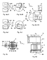
- FIG. 1a is a perspective view of the mail piece receiving device 1 from the top right front shown in a first variant.
- Last has a height (ie, a z-direction extension), a depth (ie, an x-direction extent), and a width (ie, y-direction extension of a right-angle coordinate system.)
- the mail piece acceptor 1 has a square cabinet shape with accessible from the outside and in each case by means of locking means lockable and unlocked accesses 9.1, 9.2, 9.3 to a plurality of chambers, each with a storage container and optional access to 9.0 to a waste container.
- the storage area 9 occupies most of the volume of the mail piece acceptance device.
- the accesses 9.1, 9.2, 9.3 serve to empty the storage area by a mail carrier company. Although only 3 accesses are drawn, however, further accesses to the mail piece storage chambers may follow to the left in the y direction.
- On the front side near the right side are arranged the following parts: a card reader cover plate 11, a user interface 12, a mail piece slot plate 13.1, a receipt dispenser 18 and a flap 17.1 of a mail piece return tray for returning unworkable mailpieces to the operator (postal customers).
- the height of the mail piece receiving device 1 advantageously corresponds to at least the average height of the user so that all actions of the user on the card reader, on the operator interface, on the mail piece slot, on the receipt output and on the flap of the mail piece return tray can be performed at an ergonomically favorable height.
- the width of the mailpiece receiving device 1 advantageously corresponds to that width of a multi-door cabinet wall.
- the depth of the mail piece receiving device 1 advantageously corresponds to at least twice the length of a longest postal item.
- the mail piece slot plate 13.1 serves as a cover for a variable opening 30 of the shaft-shaped feed channel and has a centrally located slot 13.0 which is used for insertion and acceptance of mailpieces and has constant dimensions corresponding to the dimensions of the largest mail piece allowed by the mail carrier for carriage.
- the mail piece acceptance device 1 is connected to a data center 20 for communication with a remote data center via a communication device 14 via a data cable 19, wherein a wired communication with other communication devices, for example via a telephone network, is made possible
- a communication device in the mail piece acceptance device 1, can also be operated without a data cable, for example via Bluetooth communication technology, or via another type of wireless communication with other communication devices, for example via WLAN.
- Each mail piece acceptance device contains a mail piece return pocket 17 as an additional mail piece buffer to which unprinted mail pieces or letters can be removed via a flap 17.1 after the user has terminated the process.
- the termination of the process can also be done automatically, for example, if the position of the mailpiece or letter is not recognized, the latter is too small in terms of allowed for carriage dimensions, if foreign bodies are recognized, are not allowed for carriage or if the user to Transport required fee can not provide.
- the items are deposited in a separate container if they are not removed by the user from the post office return box.
- the separate container (not shown) can be subsequently emptied via a flap 9.0.
- no staff in the post office or similar facilities is required, resulting in corresponding cost advantages. Particular attention is drawn to those cost advantages that arise during maintenance. The latter causes less effort since the mailpiece acceptor does not contain a balance.
- a user inserts his debit, credit, debit or debit card into the slot of the card reader cover plate 11 of the mail acceptance device.
- a PIN number is entered. He is identified and a settlement is possible.
- the user gives an indicium value or the information for the service provider about the dimensions of the mailpiece and possibly a number of mail items to be franked, e.g. via touch screen or keyboard.
- the arrangement is no longer subject to the calibration obligation, since no balance is available.
- the shoot of the feed channel 13 is opened by means of the first device 3.
- the mail pieces 2a are successively inserted into the slot of the plate 13.1 and land in the feed channel 13. They are fed by the latter into the mail piece acceptance device.
- a recognition of the orientation of the mail pieces before producing a different orientation and orientation In the result an image of the front and back is created in the controller 10, from which information on the existing orientation of the mail piece are derived.
- the required for printing with the fee orientation of the mail piece with the fourth device 6 is controlled by the controller 10, which also includes a billing and booking unit.
- the now correct postal item is supplied to the franking of the printing device 8 and marked by being printed at least with the fee and an identifier, which subsequently provides the service provider with appropriate information.
- the devices 3 to 8 contain sensors and actuators which are operatively connected to the controller 10 - which, for reasons of clarity in the FIG. 1b was not fully presented.
- a first light barrier L3-S3 is arranged at the beginning of the feed channel, inside or near the first device 3.
- a sensor S3 of the first light barrier emits a signal when an edge of the mail piece is fed and is - in a manner not shown - electrically connected to the controller, which determines the supply of a mailpiece in the feed channel.
- the sensor S3 receives light from a light source L3 until the light beam is interrupted by a mailpiece.
- a second photo-interrupter L4-S4 is arranged at the end of the feed channel 13 and signals the end of the feeding of the mailpiece.
- a second light barrier sensor S4 receives light from a light source L4 until the light beam is interrupted by a mailpiece. The latter is the case when a predetermined position of the mail piece is reached, which may trigger a blockage of the feed channel 13 if necessary by closing the shutter of the first device 3, if no further mail item is to be supplied.
- the sensors and actuators of the devices are all connected - not shown, in a manner known per se - to the controller 10 and will be explained later in connection with the function of these devices.
- a further light barrier S9-L9 arranged in storage repository 9 can, for example, monitor all storage containers at once to determine whether one of the containers is already full.
- a sensor S9 receives light from a light source L9 until a predetermined degree of filling of one of the storage containers 9.01, 9.02 and 9.03 is reached.
- the billing takes place immediately at the beginning of the printout in the postal security device 10.2 and / or either directly immediately via the communication device 14 by means of a data connection to the remote data center or consolidated at a later time.
- the security device 10.2 detects and stores the number and / or properties of the mail pieces associated with the user. In. If required, a receipt print can be made available to the user.
- an OCR reader is also included in the third device 5 which scans the information on at least one page (preferably the address page) of the mail item detected by the controller 10, the controller having a corresponding user program.
- a suitable applied identifier and the assignment of the two features to each other in a further processing step at the service provider a mail piece tracking function, which is also known as "track and trace" realized.
- a mail piece 2 in particular an envelope, can for example lie on a table (not shown) in any of the possible different initial positions and is rotated by the operator into one of the feed positions I, II, III or IV shown before a throw-in into the slot Mail acceptance device takes place, wherein the opening width of the closure is adjusted by the first device.
- FIG. 3a shows a front view of a plate with a slot for insertion of mailpieces.
- a mail piece slot plate 13.1 is mounted with a slot 13.0 for insertion of, for example, edge pieces.
- the slot 13.1 has the dimensions 50 mg - 250 mm.
- the smallest piece of mail should have a minimum dimension of 70 mm. 100 mm or 90 mm. 140 mm (standard letter).
- a letter slot for a maxi letter measures a maximum of 50 mm. 250 mm.
- a letter slot for a large letter measures a maximum of 20 mm. 250 mm.
- a letter slot for a compact letter measures a maximum of 10 mm. 125 mm.
- FIG. 3b shows a front view of an apparatus 3 for adjusting the opening width of the shutter of the mailing channel for a small opening width and the basic arrangement of Baugrup-pen to its control.
- the shutter is formed by first and second shutter jaws 31 and 32 and driven by a controller 10 driven by a first motor (M1) 15 and second motor (M2) 16.
- M1 first motor
- M2 second motor
- the closure is kept completely closed as long as the user has not identified himself.
- the mailpiece acceptors can thereby be effectively protected from the unauthorized entry of items that could cause harm.
- the user As soon as the user has identified himself, he can be held responsible and liable for any damage he has caused or is demonstrably subject to vandalism.
- the closure In another variant (without vandalism protection), the closure is never completely closed and there is always a slot for mail pieces (letter slot), which have the smallest possible dimensions allowed by the postal carrier.
- the device 3 can therefore be abbreviated also referred to as Schlitzissenverstell Rhein.
- the closure has a square-shaped opening 30 (letter slot) and two immediately adjacent immovable sides and two immediately adjacent movable sides in order to enlarge the letter slot.
- the movable sides are formed by a movable L-shaped locking jaw 32, which faces an L-shaped locking jaw 31 which is immovably mounted on a chassis 310, wherein the movable locking jaw 32 has a rotated by 180 ° to the right L-shape and is arranged opposite the non-rotated L-shaped closure jaws 31.
- a bearing 311 arranged opposite the latter is fixed or formed, which serves to guide a first slide 312 in the z-direction and opposite thereto. The movement is thereby transmitted from the second motor 16 via a - not shown - drive device on the first rail 312.
- the first carriage 312 carries a second bearing 313 for a second carriage 321.
- the latter is driven by the first motor 15 via a - not shown - drive device in the y-direction and moves opposite thereto.
- the second carriage 321 is integrally formed or rigidly mounted on the outer side of the movable rotated closure jaw 32, with which at least one movement in the y-direction or opposite to the closure jaw 32 is transmitted.
- Each of the two closure jaws has an L-shape, i. a bent from the longer arm at a right angle shorter arm 322nd
- the motors 15 and 16 may be formed as stepper motors M1 and M2. From an end point, after the delivery of a number of drive pulses by the control unit 10 to the stepper motors M1 and M2, a predetermined opening width of the shutter can be achieved.
- two limit switches 33 and 34 are implemented as microswitches and provide a signal to the controller when the movement reaches an endpoint.
- the end of the shorter arm 322 of the second locking jaw 32 for example, moved in the y direction to the longer arm 314 of the first closure jaw 31 and reaches its end position, when the end of the shorter arm 322 of the second closure jaw 32, the second Endlageschalter 34th actuated, the latter emits a ground signal to the controller 10 via its output u.
- a resilient actuating lever 341 is inserted between the closing jaw 32 and the second closing position switch 34.
- a rotatably mounted ball or a wheel 331 is used to avoid abrasion.
- another sub-variant of the first variant of the shutter is either driven by alternative electromagnetic actuators Actuators, linear motors, etc. or pneumatically operated actuators.
- the Figure 3c shows a front view of an apparatus for adjusting the opening width of the closure of the mailing channel for a large opening width and principle arrangement of assemblies for its control.
- the L-shaped movable shutter 32 of the shutter rotated by 180 ° to the right was moved by means of the first carriage 312 and the second carriage 321 to a position corresponding to a maximum opening width of the shutter of the mailing passage.
- the Figures 4a-I, 4a-II, 4a-III, 4a-IV show a representation of different Zubowlagen I to IV of the mail pieces 2a when fed into a channel (not shown) of the mail piece receiving device in plan view on x / y plane.
- the two Figures 4a-I, 4a-II, 4a-III and 4a-IV each initial situation shown on the top left corresponds to that which already on the basis of Figures 2-I, 2-II, 2-III and 2-IV were explained.
- the lower starting point dargestelle is to indicate the variety of possible starting positions or illustrate that not only a single starting position occurs in practice.
- the item of mail is manually rotated for delivery in such a way that it fits into the insertion slot.
- An insertion into the insertion slot of the mailpiece acceptance device is possible for large mail formats (maxi letters and large letters) only in a longitudinal position.
- large mail formats maximum letters and large letters
- transverse position of large post formats whose length would exceed the set height of the insertion slot of the closure ten. They can therefore not be inserted in the transverse position in the insertion slot of the closure of the feed channel of the mail piece receiving device.
- the transverse position would only be possible if the opening width of the insertion slot was previously set too large.
- the feed position is scanned by the scanning device 5a, 5b. Transverse positions of the mailpiece can basically be recorded and provided for subsequent modulation and return via return tray.
- the eight feed layers comprise the aforementioned four feed positions Figures 2-I, 2-II, 2-III and 2-IV for postal items in longitudinal position and four additional Zulitelagen for mail pieces in transverse position.
- the transverse position is apparent from the longitudinal position when the mailpieces are rotated at an angle of + 90 ° to the left.
- the cost-conscious operator will, however, usually select a cost-effective opening width of the insertion slot of the closure of the feed channel and thus the Lägslage in the supply of a mailpiece.
- the first and second movement of the mail pieces are feeding movements which are carried out by a separate device (not shown) for feeding a mail piece to a turntable.
- a separate device for feeding a mail piece to a turntable.
- a piece of mail can be brought to a slide after passing through a switch, which runs in space so that the mail piece comes in lateral position in the appropriate position on a turntable of the fourth device 6.
- FIGS. 4c-I / III, 4c-II / IV show a top view of a simplified illustrated device 6 for positional alignment, before and after output of the mail piece in the delivery position and during printing during transport of the mail piece in the y direction.
- the Figure 4c-I / III shows a first discharge position of a mail item in the first and fourth quarters Q1, Q4 of a turntable 60 before output of the mail piece in the discharge position 2b.
- the output is effected by means of a first output movement C1 in the x direction.
- the Figure 4c-II / IV shows a second discharge position of a mail piece in the second and third quarters Q2, Q3 of the turntable 60 before outputting the mail piece in the discharge position 2b.
- the output is effected by means of a second output movement C2 in the same x direction, wherein a second distance covered by the mail piece during the second output movement C2 is longer than a first distance traveled during the first output movement C1.
- the mailpieces are in the delivery and discharge position on the back and are all oriented just as well oriented for further transport.
- FIGS. 5a-I, 5a-II, 5a-III, 5a-IV show a simplified representation of the top view of the turntable 60 with pivoting device 67 after a quarter turn of the pivoting device about an axis q parallel to the x-direction.
- the Mail piece lies in each case on the back within the swivel device. The latter has been cut open to illustrate the mailpiece orientation. With arrows A1 and A2, the movements of the pivoting device are illustrated.
- the turntable 60 with pivoting device 67 is part of the fourth device 6 for automatic position orientation and position alignment, which is a mail piece after passing through the second device 4 for feeding mail pieces in the feed channel and the third device 5 for position-tasting a mail piece in the feed reached.
- FIGS. 5b-1, 5b-II, 5b-III, 5b-IV show a simplified representation of the top view of the turntable with pivoting device after a quarter turn of the turntable about an axis - not shown - parallel to the z-direction, which is orthogonal to the x / y surface.
- the movements were each represented by arrows B1, B2, B3 and B4.
- FIG. 1 show a plan view of a mail piece 2b in the discharge position after each movement (black arrow) from the group B, corresponding to that of Figs Figures 4c-I / III and 4c-II / IV already explained movements C1 and C2 and before a movement (white arrow) of the mailpiece in the transport direction (y-direction).
- the illustrated address field 2.1 illustrates the supine position of the mail piece.
- FIG. 6a shows a top view of a device 6 for the correct orientation of mail pieces, with a turntable 60 and with a pivoting device 67 in the feeding phase of a mail piece in the first feed position I.
- the mail piece 2a-I passes through the edge standing x-direction the second Device 4 for feeding mail items into the feed channel and third device 5 for position scanning a mail piece before reaching the fourth device 6.
- the pivoting device 67 is over the Transport means 61, 62, 63, 64 arranged and formed for collecting in the feed phase on the edge standing mail pieces. It is attached to a shaft 651 which lies on a rotation axis q parallel to the x-direction.
- the FIG. 6b shows a side view of the feed channel 13 and the pivoting device 67 of the fourth device 6.
- the feed channel 13 is constructed professionally and consists of at least one slit plate 13.1, two side walls 13.2, 13.4 and a rear wall 13.3. He is also equipped with - not shown - sensors or light barriers, means of transport and holding means for holding the mail piece until the time of leaving the feed channel 13.
- the item of mail 2 is drawn below the feed channel 13 from this outstanding at the time of leaving the feed channel 13, for example, solely due to the force of gravity.
- the pivoting device 67 is arranged on the turntable 60, which is mounted centrally on a shaft 681 through whose center a rotation axis r runs parallel to the z-direction.
- FIG. 6c shows a front view of the device 6 for the correct alignment of mail pieces in the y / z plane, with a turntable 60 and with a pivoting device 67 in the feed phase of a post-piece 2a-I in the feed position I after the time of leaving the feed channel.
- the pivoting device 67 is rotated so that one of the openings facing upwards in the z-direction and has a corresponding opening width for a mail piece with a maximum thickness (50 mm).
- a third motor 66 for example a DC motor M3, with a shaft 661 for driving the transport means 61, 62, 63, 64, for example via a drive belt 613 is arranged.
- the transporting means 61 has a driven roller 611 and a non-driven pulley 612 for a conveyor belt 614.
- the driven roller 611 and the non-driven roller 612 are rotatably mounted on a respective shaft 615, 616 above the turntable 60 in bearings ( Fig.6d ) stored.
- the bearings are spaced from the surface of the turntable 60 by means of spacers 601, 602.
- a fourth motor 68 for example, a stepper motor M4 is arranged, the shaft 681 with the bottom of the turntable 60 centric positive and non-positively verbun-the.
- the pivoting device 67 is mounted on a shaft 651, which is arranged centrally in the region between the rollers 611, 612 parallel to the rotary shafts 615, 616 and is rotatably mounted in the x direction.
- the pivoting device 67 can be pivoted in the clockwise direction A1 or in the opposite direction in the direction A2.
- the pivoting device 67 consists of a rectangular frame which is folded in the middle V-shaped and fixed on the shaft 651, for example by spot welding.
- the V-folded portion of the frame extends from one-half to one full length corresponding to the diameter-driven roller 611 of the first transport 61.
- the frame folded in this way has a rectangular opening whose dimensions are determined by the dimensions of the largest postal items to be transported.
- the rectangular opening is open on four sides, ie in the position shown to the front and rear and up and down, for a mailpiece and is bounded by side walls.
- FIG. 6d shows a side view of the pivoting device 67 in the x / z plane.
- a fifth motor 65 for example, a DC motor M5, which is disposed and mounted on the turntable 60 in the position shown or in another position.
- the plate 671 passes below the top of the conveyor belts when the fifth motor 65 is driven and the pivoting device 67 is pivoted.
- the rotation axis q which is parallel to the x-axis, extends centrally of the shaft 651.
- the shaft 651 is rotatably mounted on the edge of the turntable 60 in opposite bearings 691, 692.
- the transport means 61, 62, 63, 64 have driven rollers which are mounted on a shaft 615, through which a rotation axis (not shown) extends, which is also parallel to the x-axis.
- the shaft 615 is driven by the third motor 66 via the drive belt 613, which is designed, for example, as a toothed belt.
- the drive can also be done alternatively in another way, for example by means of drive chain and gears.
- the controller (not shown) is electrically connected to the motors and programmed to drive the drives accordingly.
- the fourth device 6 for automatic position alignment of a mail piece has at least one drive, which is controlled by the controller 10 to transfer the mail piece from a (random) feed position 2a before issuing the mail piece in a predetermined output position 2b, wherein all mail pieces in the Ausgabelage lie on the back and are all oriented just as well for further transport.
- plate 671 and an opposite plate may be attached as side walls, for example wire mesh or wire clips suitably shaped to hold mailpieces.
- FIG. 6e shows a front view of the device 6 for the correct alignment of mail pieces in the y / z plane, ie in a phase after pivoting a mail item 2.
- the plate 671 and the shaft 651 are below and the plate 672 is above the top of the conveyor belts.
- FIG. 6f shows a side view of the device for the correct alignment of mailpieces in the x / z plane, after a quarter turn of the pivoting device about an axis parallel to the z-direction.
- the slot in the plate 671 is wide enough that the function of the transport means 61, namely the transport of the mailpiece, is not hindered.
- FIG. 6g shows a side view of a mail item in Ausgabelage during transport in the x direction from the pivoting device.
- the mailpiece 2b lies on the back, which can be seen on the flap 2.3.
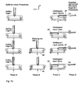
- the Figure 7a shows a perspective view of a second variant of a mail piece receiving device 1 from the front right above.
- a card reader cover plate 11 ' On the front side near the right side are a card reader cover plate 11 ', a user interface 12', a mail piece slot plate 13.1, a receipt dispenser 18 'and a flap 17.1' of a mail piece return tray for returning unworkable mailpieces to the operator (post office customers) and possibly one Access 9.0 'arranged to the waste container.
- FIG. 7b shows a simplified representation of a plan view of the turntable 60 'with mailpiece in the transport path for transport in the x-direction and for printing according to a second variant of the mail piece receiving device.
- the output of the mail item into the delivery position 2b ' is effected by means of a third motor 66' of the mail piece acceptance device (1 ') which is actuated by a controller 10' for dispensing the mail piece opposite to the y direction by means of a third or fourth dispensing movement C3 or C4, wherein a fourth distance traveled by the mail item during the fourth output movement C4 is longer than a third distance traveled during the third output movement C3.
- the mail piece 2b retains, after rotation, a recumbent position relative to the standing position when fed in the third device with the scanners 5a', 5b 'for position scanning of a mail piece in the feed channel.
- This maintained position of the mailpiece 2c '( Figure 7b ) is opposite to that of the item of mail 2c 4c-I / III rotated about an axis parallel to the z-direction at an angle of -90 ° clockwise.
- the programming of the controller 10 'for controlling the fourth device 6' is adapted accordingly.
- the rotation of the turntable can also be done before pivoting or folding the mailpieces, as described below with reference to Fig. 7c is explained.
- FIG. 7c shows a front view of the turntable with pivoting in the y / z plane and a mailpiece in phases, which run in the mail piece receiving device 1 'of the second variant.
- the mail piece is, for example, an enveloped letter with address field.
- the longitudinal edge lies on the fold edge of the envelope flap of the envelope or just opposite the address window (not shown).
- Phase B illustrates that for two out of four feed layers of a mail piece fed on the longitudinal edge, no rotation is required. This is the aforementioned case a).
- Phase B also illustrates, for the other two of the four feed layers of a mail item, that by means of the turntable 60 a rotation about an axis parallel to the z-direction must be made at an angle of 180 °. This is the aforementioned case b).
- the mail piece leaves the swivel device through the same opening through which the mail piece was fed to the swivel device.
- the mail piece leaves the swivel device through the opposite opening, i. not through the same opening through which the mailpiece was fed to the pivoting device.
- Phase D illustrates the dispensing of the mail piece on the back.
- the mail piece leaves the swivel device with a third movement C3 on a short path.
- the mail piece leaves the swivel device with a fourth movement C4 on a longer path compared to the former path, both paths leading in the opposite direction to the y direction.
- An implementation of the fourth movement C4 requires two opposite openings in the pivoting device 67 of the device 6 for the correct alignment of mail items, which is apparent from the Figures 6a and 6b evident. Both openings of the pivoting device 67 are shown open in the z-direction, wherein the movement (white arrow) of the mailpiece ends on a turntable 60.
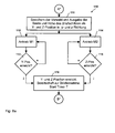
- the pre-selection made by the user for setting the insertion opening of the mail piece acceptance device is queried by the query steps 103, 104 and 105 and can be supplemented by further query steps were if the due to changed postal regulations or country dependent or carrier dependent other postal regulations should be required.
- the rule here is that the second area code II is branched if the first area code I was not recognized as selected. If the second area code II is not recognized as selected, then the third area code III is branched off and so on until a K-th area code is requested. If the latter is not recognized as selected, then the beginning of the first interrogation step 101 is branched back to the beginning.
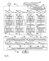
- the FIG. 8a shows a subroutine 110 for adjusting the insertion opening of the mail acceptance device, which runs after reaching the first point (A *) in the flowchart 100.
- the preselection of the insertion opening (mail slot size) made by the user is stored and the width and height of the desired insertion opening are output in the form of Parameters that identify the Y and Z positions.
- the corresponding Y and Z positions are achieved when the sealing jaws are moved in the y and z directions in order to set the opening width of the closure of the mail piece feed channel.
- the subroutine for setting the slot size in the third step (110) comprises a second sub-step (112) for controlling a motor M1 and a fourth sub-step (114) for controlling a second motor M2, wherein in the respectively following third and fifth subquery step (113 and 115), whether the Y-position and the Z-position have already been reached, and otherwise the first motor M1 and the second motor M2 for jaw adjustment are further driven.
- a timer of the controller 10 is started, which runs until a preset time / counter value is reached is. The latter determines how long a readiness of the mail piece acceptance device to take letter acceptance. Reaching the preset time / counter value by the timer is monitored in step 106 of the schedule 100. The timer is reset (not shown) when branching back to the first query step 101 via further steps. After setting the opening size of the shutter (slot size) in the subroutine 110, the second point (B *) in the schedule 100 is reached.
- the FIG. 8b shows a subroutine 120 for scanning the front and back of a mailpiece and for detecting the position of a mailpiece in the mailpiece acceptor.
- a mail item is retrieved in the query step 117 and then branched to the first sub-step 121 of the subroutine 120 when a mail piece has been inserted into the opening (letter slot) of the shutter of the feed channel, as indicated by the corresponding sen Sources is detected in the feed. Otherwise, if no mailpiece entry was detected in query step 117, then via step 118, a "user mail item" is issued for issuing a user advice and branched back to item (B) via sixth inquiry step 106.
- the first sub-step 121 of the subroutine 120 a scanning of the front and back of the mailpiece and an evaluation of the scan data.
- a first subquery step 127 it may be decided whether the mailpiece is too small. The latter is the case if the minimum dimensions of a mail item specified by the mail carrier are undershot. Then branch to the fourth point (D *). Otherwise, the first subquery step 127 branches to a second subquery step 122 for checking whether the front side of a To the left of the feed channel for mail pieces arranged scanning was detected. If this is not the case, then the third subquery step 123 branches to check whether the front side has been recognized by a scanning device arranged on the right of the mail piece feed channel.
- a sub-step 126 for controlling the mail piece to return it via the tray 17 is branched to the nineteenth step 119 of the schedule 100 to display a user notice "mailpiece return".
- the second subquery step 122 branches to a fourth subquery step 124 when the front side has been recognized by a scanner located on the left of the mail piece feed channel.
- the third subquery step 123 branches to a fifth subquery step 125 when the front side has been recognized by a scanner arranged on the right side of the mail piece feed channel.
- the fourth sub-query step 124 it is determined whether a mailpiece is upside down because it has been fed upright on the flap edge, and then branches to a first memory sub-step 128.1 to provide a first type 1 mailing orientation corresponding to a first feed position otherwise, if a mailpiece is not upside down, branching from the fourth subquery step 124 to a second memory sub-step 128.2 to store a second type 2 of mailpiece alignment corresponding to a second feed position II.
- the fifth subquery step 125 From the fifth subquery step 125, if a mail piece is upside down, i.e., a mail piece is turned upside down. is fed standing on the edge with flap, branched to a third memory sub-step 128.3 to store a third type 3 of the orientation of the mail pieces corresponding to the third feed position III. Otherwise, if a mailpiece is not upside down, the fifth subquery step 125 branches to a fourth first memory sub-step 128.4 to store a fourth type 4 of mail item alignment corresponding to the fourth feed position IV. After storing the type in the first, second, third or memory sub-step, the third point (C *) is reached.
- the third device for scanning the mail piece blanket is operatively connected to the controller, which on the one hand contains the subroutine for scanning and evaluation of the sampled data and on the other hand a subroutine for positional orientation stored nonvolatilely in a memory, which is accessed by a microprocessor of the controller during operation as soon as a sampling result is available.
- the FIG. 8c shows subroutines for position alignment of a mail piece in the mail piece acceptance device, for generating an identifier or billing number, billing of the mailpiece dispatch order, booking of the transport fee, for printing the marking (identifier), if necessary for printing a receipt and for filing in the storage container.
- a subroutine 130 is provided for registering a mail piece in the mail piece acceptor and subroutine 160 is for storage in the tray.
- subroutine 150 with a first subroutine 151 for generating an account number and a second subroutine 152 for billing the mail item dispatch order and posting, the subroutines being executed by the processor of the postal security service. Device to be processed.
- sub-subroutine 153 for printing the identifier or billing number
- sub-subroutine 154 for printing an acknowledgment and the aforementioned sub-program 160 for storage in the storage container, these subroutines also being processed by the processor of the mainboard of the controller 10. On the latter will not be discussed here in more detail, because the transport of a mail piece with printing the mark, receipt printing and storage are known in the art.
- the position alignment subroutine 130 starts after reaching the fourth point (D *) with a query on the first subquery step 131 of the first type 1 of the mail pieces alignment. If a type 1 exists, a sub-step 132 is reached, wherein the controller controls the motor 65 to drive the pivoting device 67 ( Fig. 6d ) to flip them in the A1 direction (to -y), ie to the right ( Fig. 6c ). After folding the pivoting device 67 to the right in the A1 direction is in the Figure 5a-I shown state before.
- the first subquery step 131 branches to the second subquery step 135. There it is queried whether a second type 2 of the alignment of the mailpieces is present. If a type 2 is present, a sub-step 136 is reached, wherein the control drives the motor 65 to drive the pivoting device 67 in order to fold it in the A2 direction (to the right), ie to the left. After folding the pivoting device 67 to the left in the A2 direction is in the Figure 5a-II shown state before.
- the second subquery step 135 branches to the third subquery step 140. There it is queried whether a third type 3 of the alignment of the mail pieces is present. If a type 3 is present, a sub-step 141 is reached, wherein the controller drives the motor 65 to drive the pivoting device 67 in order to move it in the A2 direction (to y), ie to fold to the left. After folding the pivoting device 67 to the left in the A2 direction is the in Figure 5a-III shown state before.
- the third subquery step 140 branches to the fourth subquery step 145. If a type 4 is present, a sub-step 146 is reached, wherein the control activates the motor 65 for driving the pivoting device 67 in order to fold it in the A1 direction (to -y), ie to the right. After folding the pivoting device 67 to the right in the A1 direction is in the Figure 5a-IV shown state before.
- a sub-step 139 for controlling the mail item for the purpose of returning or storing it in the waste container.
- the waste container can be advantageously arranged under the return tray and separated by a sieve. Small pieces of metal and other waste fall through the screen, while too little or unaddressed mail remains in the return tray.
- a step 119 is issued for issuing a corresponding user hint to prompt the user to empty the return tray.
- a sub-step 133 is reached after the sub-step 132, wherein the control drives the motor 68 for driving the turntable 60 ( Fig. 6c ) in order to rotate these about the axis r parallel to the z direction in the B1 direction by the angle of 90 ° in the counterclockwise direction ( Fig. 6f ). After turning the turntable is in the Figure 5b-I shown state before.
- a sub-step 137 is reached after the sub-step 136, wherein the control drives the motor 68 to drive the turntable 60 to this by the angle of 90 to the axis r parallel to the z-direction in the B2 direction ° to turn counterclockwise. After turning the turntable is in the Figure 5b-II shown state before.
- a sub-step 142 is reached after the sub-step 141, wherein the control drives the motor 68 to drive the turntable 60 to this by the angle of 90 to the axis r parallel to the z-direction in B3 direction ° to turn clockwise. After turning the turntable is in the Figure 5b-III shown state before.
- a sub-step 147 is reached after the sub-step 146, whereby the control drives the motor 68 for driving the turntable 60 to move it around the axis r parallel to the z-direction in the B4 direction by the angle of 90 ° to turn clockwise. After turning the turntable is in the Figure 5b-IV shown state before.
- a tape transport takes place in the sub-steps 134, 138, 143 and 148 for moving the mail item off the turntable, before a fifth point (E *) is reached.
- the motor 66 is driven by the controller to a - in the Fig. 6d Turned shaft 615 clockwise to rotate, ie the shaft and thus the - in the Fig. 6a shown - conveyor belts 61, 62, 63 and 64 are brought to the right turn.
- the motor 66 is controlled by the controller to a - in the Fig. 6d Shaft 615 to rotate in the counterclockwise direction, ie the shaft and thus also in the Fig. 6a shown - conveyor belts 61, 62, 63 and 64 are brought to the left rotation.
- subroutine 150 After subroutine 130 for position alignment, subroutine 150, in whose first subroutine 151 an individual identifier for the mailpiece is generated by the PSD of the controller, in whose second subroutine 152 the posting is made, in its third subroutine 153 the transport of the mailpiece by the sixth Transport device is started and printed by means of the printer of the fifth device, an identifier on the mailpiece and in the fourth sub-subroutine 154 a Qittungs horrer is driven to a document to prove the promotion order for the user, ie Postal customers to print.
- Subroutine 150 is followed by subroutine 160 for filing the inserted mail item in the filing bin, which has subquery steps 161, 162, 163, 164, so that a filing in the filing bin occurs in the subsequent sub-step 166 depending on the preselected size of the set opening width when the query condition is met.
- the prefix dialed by the user is queried in sub-querying steps 161, 162, 163 and optionally, if required, at least one further sub-querying step 164 (drawn in dash-dotted lines). It is true that in each case to the subsequent query of the area code K is branched if the immediately preceding query the area code K-1 was not recognized as stored.
- a step 165 for storage in the storage container takes place depending on the area code a control of turnouts for the corresponding storage.
Abstract
Description
Die Erfindung betrifft eine Einrichtung und ein Verfahren zur Poststückannahme, gemäß der im Oberbegriff der Patentansprüche 1 und 10 angegebenen Art und ist für eine Postverarbeitungsmaschine geeignet, die im Postamt, in Läden, Tankstellen und/oder an öffentlichen Plätzen oder privaten Einrichtungen aufgestellt und zur Poststückannahme eingesetzt wird.The invention relates to a device and a method for mail acceptance, according to the type specified in the preamble of
Aus dem europäischen Patent
Aus der europäischen Patentanmeldung
In sogenannten Aufgabestationen erfolgt eine automatische Postgut-annahme und in Abgabestationen wird die Postverteilung durch einen Postbeförderer nach einem Frankieren des Postgutes vorbereitet, wobei in jeder Aufgabestation ein Drucken eines Quittungsbelegs für den Postkunden und ein Drucken einer maschinenlesbaren Markierung auf das Poststück erfolgt. Zur Zwischenspeicherung des markierten Postgutes im Aufbewahrungsbehälter der Aufgabestation, kommt eine Eingabe weiterer relevanter Daten in den ersten Speicher der Aufgabestation, wobei aufgrund der Markierung die vorgenannten Daten zum Poststück zugeordnet gespeichert und wieder abgerufen werden können. Die Eingabe kann mit Unterstützung einer kundenbezogenen Chipkarte erfolgen, die in eine erste Lese-/Schreibeinheit gesteckt wird und zur Identifizierung der kundenbezogenen Chipkarte bzw. des Kunden vorgenommen wird. Das Abrufen der Daten erfolgt beispielsweise ebenfalls mittels der speziellen ersten Lese-/Schreibeinheit, indem eine Beförderer-Chipkarte eingesteckt wird, zum Laden der Buchungsdaten aus dem ersten Speicher in einen Speicher der speziellen Befördererkarte. Dann erfolgt eine Entleerung des Aufbewahrungsbehälters der Aufgabestation und ein Transport des markierten Postgutes und der speziellen Befördererkarte durch einen ersten Postbeförderer zu einer entfernten Frankiermaschine in einer Abgabestation. Nach einem Einstecken der speziellen Befördererkarte in eine zweite Lese-/Schreibeinheit und Laden der Buchungsdaten aus dem Speicher der speziellen Befördererkarte in einen zweiten Speicher der Frankiermaschine erfolgt eine Frankierung des Postgutes in der Abgabestation entsprechend den Daten, die im zweiten Speicher zugeordnet zu der Markierungsinformation gespeichert vorliegen, welche aus der auf dem Poststück aufgedruckten abtastbaren Markierung zurückgewonnen wird. Für die Aufgabestationen wurden drei Varianten vorgeschlagen. Die einfachste Variante besteht aus einem Aufbewahrungsbehälter für Poststücke und einem Slot zum Einstecken einer Kundenkarte und zugehöriger Elektronik sowie einen an dieser angeschlossenen gewöhnlichen Kundenbelegdrucker, der sowohl den Beleg als auch die Markierung auf einen selbstklebenden Papierstreifen druckt. Das macht es erforderlich, dass der Streifen mit der Markierung evtl. vom Kunden selbst auf das Poststück geklebt wird, bevor es in den Aufbewahrungsbehälter gelangt. Eine entfernte Abgabestation enthält einen Markierungs-Lesevorrichtung und ein Frankiermaschinensystem. Das letztere besteht vorzugsweise aus einer automatischen Zuführungs-Station, einer dynamischen Waage-Station und einer Frankierstation. Die Markierungs-Lesevorrichtung kann in das Frankiermaschinensystem integriert werden. Das Postgutverarbeitungssystem besteht somit aus einer Vielzahl an Postgut-Aufgabestationen und einer Vielzahl an Postgut-Abgabestationen zwischen denen ein (privater) Postbeförderer agiert, um Aufbewahrungsbehälter für Poststücke zu entleeren und Poststücke zu den Postgut-Abgabestation zu befördern, welche die Frankierung der Poststücke vornehmen. Wenn die Postgut-Aufgabestationen einfach aufgebaut sind, müssen die Postgut-Abgabestationen komplexer aufgebaut sein, d.h. mit zusätzlichen Stationen, wie zum Beispiel mit einer dynamischen Waage-Station ausgestattet werden. Umgekehrt kann eine Postgut-Abgabestation einfach (ohne Waage) aufgebaut sein, wenn die Postgut-Aufgabestationen bereits eine Waage aufweisen, d.h. komplexer ausgestatet sind. Somit ist eine Vielzahl an Ausgestaltungsvarianten für eine Postgutverarbeitungssystem denkbar. Nachteilig ist, dass einerseits eine Überfüllung der Poststückannahmeeinrichtung möglich ist und anderer-seits eine Entleerung der Poststückannahmeeinrichtungen in festen Zeitabständen auch dann erfolgt, wenn dort noch gar kein Poststück gelagert wurde. Außerdem unterliegen Stationen mit einer Waage in der Regel der Eichpflicht, was erhöhte Wartungskosten verursacht.In so-called picking stations an automatic mail acceptance and in distribution stations, the mail distribution is prepared by a mail carrier after a franking of the mail, with each post office a printing of a receipt receipt for the postal customer and printing a machine-readable mark on the mail piece. For temporary storage of the marked mail in the storage container of the loading station, an input of other relevant data is in the first memory of the loading station, which due to the marking, the aforementioned data can be stored assigned to the mail piece and retrieved again. The input can be done with the support of a customer-related chip card, which is plugged into a first read / write unit and for identifying the customer-related chip card or the customer is made. The retrieval of the data, for example, also by means of the special first read / write unit by a carrier chip card is inserted, for loading the booking data from the first memory in a memory of the special carrier card. Then, a discharge of the storage container of the loading station and a transport of the marked mail and the special carrier card by a first mail carrier to a remote franking machine in a dispensing station. After inserting the special carrier card into a second read / write unit and loading the booking data from the memory of the special carrier card into a second memory of the postage meter, the mail is franked in the dispensing station in accordance with the data stored in the second memory associated with the tag information which is recovered from the scannable mark printed on the mail piece. For the feeding stations, three variants were proposed. The simplest variant consists of a storage container for mail pieces and a slot for inserting a customer card and associated electronics and a connected to this ordinary customer receipt printer, which prints both the receipt and the mark on a self-adhesive paper strip. This requires that the strip with the mark may be glued to the mail piece by the customer himself before entering the storage box. A remote dispensing station includes a marker reader and a postage meter system. The latter preferably consists of an automatic feeder station, a dynamic weighing station and a franking station. The marker reading device can be integrated into the postage meter system. The mail processing system thus consists of a plurality of mailing stations and a plurality of mailing stations between which a (private) mail carrier operates to empty mail piece storage containers and convey mail pieces to the mail dispensing station which stamp the mailpieces. If the mailing stations are simply constructed, the mailing stations must be more complex, ie, equipped with additional stations, such as a dynamic scale station. Conversely, a mail delivery station can be constructed simply (without scales) if the mail delivery stations already have a scale, ie are more complex ausgestatet. Thus, a variety of design variants for a mail processing system is conceivable. The disadvantage is that, on the one hand, an overfilling of the mail piece acceptance device is possible and, on the other hand, an emptying of the mail piece acceptance devices in a fixed position Time intervals also takes place, if there was no postal item stored. In addition, stations with a scale are usually subject to verification, which causes increased maintenance costs.
Aus der
Die Postbehörden haben weitere Vorschläge zu neuen Dienstleistungen und zur Ausgestaltung oder Veränderung bestehender Dienstleistungen unterbreitet, wobei immer öfter neue Automaten eingesetzt werden. Dabei ist das Problem der "ersten Meile" zu überwinden, d.h. öffentliche und private Briefdienstleister müssen die Poststücke erst einmal selbst bekommen, um diese dann transportieren zu können. Die Deutsche Post AG (DPAG) war bis zum Jahre 2007 verpfichtet wenigstens 12000 Filialen zu betreiben. Ab dem Jahre 2008 ist das nicht mehr gesetzlich vorgeschrieben und eine Briefsendung bis 50 g kann nun auch von den Wettbewerbern der DPAG befördert werden, die aber nach Einführung von Mindestlöhnen kaum eine Chance sehen, rentabel zu arbeiten.Postal authorities have made further proposals on new services and on the design or modification of existing services, with more and more new vending machines being used. Thereby the problem of the "first mile" has to be overcome, i. public and private mail service providers have to get the mail pieces themselves first, in order to then be able to transport them. Deutsche Post AG (DPAG) was obliged until the year 2007 to operate at least 12,000 branches. From the year 2008, this is no longer required by law and a mailing to 50 g can now be promoted by the competitors of the DPAG, but see after the introduction of minimum wages hardly a chance to work profitably.
Während einerseits in Folge dessen nur kleinere Dienstleister oder ausländische Billiglohn-Dienstleister agieren, löst die DPAG dieses Problem durch Automatisierung mittels der neuen Automaten Post24/7 neben den bekannten Briefannahmestellen (früher Postämter) und Briefkästen. Die neuen Automaten vom Typ Post24/7 sind mit Briefmarkenspendern und Briefkästen gekoppelt. Vom Briefmarkenspender muß der Postkunde zuerst Briefmarken ziehen und auf ein Poststück aufkleben, welches dann in einen benachbarten konventionellen Briefkasten vom Postkunden eingeworfen werden kann. An der Rückseite des Automaten vom Typ Post24/7 ist eine Packstation angeordnet. Eine elektrische Paketfachanlage und ein Verfahren zu ihrem Betrieb ist aus dem europäischen Patent
Registrierte Kunden können sich auch Sendungen an die Post24/7-Station schicken lassen. Sie werden dann per eMail/SMS benachrichtigt und können die Sendung unabhängig von Öffnungszeiten abholen.Registered customers can also have shipments sent to the Post24 / 7 station. You will then be notified by email / SMS and can pick up the shipment regardless of opening hours.
Den Postbehörden einer Mehrzahl an Ländern und den privaten Dienst-leistern ist ein Verfahren bekannt, dass davon ausgeht, dass die ausgelieferte Post vom Kunden freigemacht worden ist. Gleichzeitig stehen die Dienstleister vor der Aufgabe Fillialleistung zu reduzieren oder in Märkte vorzudringen, in denen der Dienstleister noch keine Filialen hat. Um Filialen komplett zu ersetzen, müssen die Briefannahmeeinrichtungen geeicht sein, solange sie ein Porto ermitteln. Wenn jedoch kein Porto ermittelt wird wird diese Aufgabe in die Briefzentren verlagert, Poststücke auszusortieren, die nicht oder nur unzureichend vom Postkunden freigemacht worden sind. Die Arbeitsweise der Briefannahmeeinrichtungen ist also mit derjenigen der Briefzentren in Verbindung zu sehen.The postal authorities of a majority of countries and private service providers are aware of a procedure that assumes that the delivered mail has been cleared by the customer. At the same time, the service providers are faced with the task of reducing branch services or penetrating markets in which the service provider does not yet have any branches. In order to completely replace branches, the letter acceptance devices must be calibrated as long as they detect a postage. However, if no postage is determined, this task is relocated to the mail centers to sort out postal items that have not or not been adequately cleared by the postal customer. The mode of operation of the letter reception centers is therefore to be seen in conjunction with that of the letter centers.
Das Sortieren im Briefzentrum der DPAG wird teilautomatisiert durchgeführt. Im Briefzentrum werden nach einer Ausrichtung und Lageorientierung der Poststücke, letztere nach den Sendungsarten zugeordneten Kategorien: Länge, Breite, Höhe und Gewicht sortiert. Die Sendungsarten der DPAG sind Postkarten, Standardbriefe, Kompaktbriefe, Großbriefe und Maxibriefe genannte Kategorien. Die Sendungen werden in kleine Fächer geworfen (
Offensichtlich können noch nicht alle Aufgaben vom Automaten übernommen werden. Der Automat Post24/7 der DPAG sortiert also keine Post, auch nicht teilweise. Das Bedürfnis nach vorsortierter Post, für welche Rabatte vom staatlichen oder privaten Postbeförderer vergeben werden, welche ein Verteilzentrum betreiben, könnte von privaten Postbeförderern befriedigt werden, die in den Postweg zum Verteilzentrum vorgeschaltet sind.Obviously not all tasks can be taken over by the machine. DPAG's post24 / 7 machine does not sort mail, not even partially. The need for pre-sorted mail, for which discounts are given by the state or private mail carrier operating a distribution center, could be met by private mail carriers upstream of the mailing center to the distribution center.
Aus dem europäischen Patent
Nach dem Eichrecht bestehen aber erhebliche Anforderungen an eichfähige Poststückannahmeeinrichtungen. Diese Anforderungen führen zu einem erheblichen Aufwand und die Lösung unterliegt trotzdem den Nachteilen aus dem Eichrecht wie z.B. der Ersteichung, Nacheichung dem Vorhalten von Alibispeichern und Zusatzeinrichtungen.According to the calibration law, however, there are considerable requirements for verifiable mailpiece acceptance devices. These requirements lead to a considerable effort and the solution is nevertheless subject to the disadvantages of the calibration law such. the initial verification, recalibration the provision of Alibispeichern and ancillary equipment.
Anfang Dezember des Jahres 2008 startete die Deutsche Post AG offiziell das bundesweite Pilotprojekt "Briefstation" an vier Standorten in Frankfurt am Main in Deutschland. Im Innern eines Automaten werden Poststücke mit Hilfe modernster Technik vermessen, gewogen und frankiert. Die Poststücke (z.B. Briefsendungen) lassen sich einzeln oder stapelweise zur Frankierung in das entsprechende Fach des Automaten legen. Zusätzlich verfügt die Briefstation über einen Briefkasten für bereits frankierte Poststücke, dessen Einwurföffnung sich erst dann öffnet, wenn der Kunde über seine Postcard identifiziert worden ist. Außerdem ist der Schlitz der Einwurföffnung größer als normal, damit auch Poststücke im Postformat Maxibriefe eingeworfen werden können. Darüber hinaus kann der Automat auch Briefmarken ausdrucken. Die Briefstation kann durch ein spezielles Behältersystem mehrere Tausend Briefe aufnehmen.At the beginning of December 2008, Deutsche Post AG officially launched the nationwide "Briefstation" pilot project at four locations in Frankfurt am Main, Germany. Inside a vending machine, postal items are measured, weighed and franked using state-of-the-art technology. The mail pieces (eg letter mail) can be placed individually or in batches for franking in the corresponding compartment of the machine. In addition, the station has a mailbox for already franked mailpieces, the opening of which opens only when the customer has been identified by his Postcard is. In addition, the slot of the opening is larger than normal, so that mail pieces in the mail format Maxibriefe can be inserted. In addition, the machine can also print stamps. The letter station can hold several thousand letters through a special container system.
Ist ein bestimmter Füllgrad vor der täglichen Leerung erreicht, wird automatisch das zuständige Briefzentrum für eine zusätzliche Leerung benachrichtigt. Und sollte einmal eine Störung vorliegen, meldet dies der clevere Automat von allein dem technischen Service.If a certain filling level is reached before the daily emptying, the responsible letter center is automatically informed for an additional emptying. And should a malfunction occur, the clever automaton reports this to the technical service alone.
Bei Briefen mit Zusatzleistung werden die Sendungsdaten sofort für die Sendungsverfolgung bereit gestellt. Der Sendungsstatus ist über das Internet-Portal der Deutschen Post AG "www.briefstatus.de" abrufbar.For letters with additional service, the shipment data is immediately made available for shipment tracking. The status of the shipment is available on the Internet portal of Deutsche Post AG " www.briefstatus.de ".
Der Erfindung liegt die Aufgabe zugrunde, ein Verfahren und eine Ein-richtung zur Poststückannahme zu schaffen, welche das Poststück bear-beitet und dennoch, obwohl die Poststückannahmeeinrichtung keine Waage aufweist, in einer Nachfolgeeinrichtung eines Postbeförderers eine korrekte Freimachung mit dem richtigen Entgelt, in richtiger Orientierung auf dem Poststück und auf der richtigen Seite des Poststückes ermöglicht.The invention has for its object to provide a method and a device for mail acceptance, which processed the mail piece and yet, although the mail piece acceptance device has no scale, in a successor of a mail carrier a correct franking with the right remuneration, in real Orientation on the mailpiece and on the right side of the mailpiece allows.
Die Poststückannahmeeinrichtung soll die Poststücke dezentral vorsortieren, lagerichtig ablegen und bis zur Abholung lagern, wobei bei der Vorsortierung die Vorder- und/oder Rückseite jedes Poststückes gescannt werden.The mail piece acceptance device is to pre-sort the mail pieces in a decentralized manner, store them in the correct position and store them until they are picked up, the front and / or back of each mail piece being scanned during pre-sorting.
Durch einen Drucker der Poststückannahmeeinrichtung soll ein Auf-druck zur Vereinfachung der weiteren Verarbeitung in der Nachfolgeein-richtung eines Postbeförderers auf jedes Poststück aufgedruckt werden.By a printer of the mail piece acceptance device, an imprint is to be printed on each mail piece for the convenience of further processing in the mailing machine follow-up direction.
Die Poststückannahmeeinrichtungen soll vor Vandalismus geschützt sein und deren Entleerung soll on demand erfolgen. Außerdem soll eine Poststückverfolgung ermöglicht werden.The Poststückannahmeeinrichtungen should be protected against vandalism and their emptying should be on demand. In addition, a mail piece tracking should be possible.
Die Aufgabe wird mit den Merkmalen der Anordnung nach dem Anspruch 1 und mit den Merkmalen des Verfahrens nach dem Anspruch 10 gelöst.The object is achieved with the features of the arrangement according to
Ausgehend von einer Poststückannahmeeinrichtung, mit einer Postgutzuführung für Poststücke, mit einer Bedienschnittstelle und mit einer Abrechnungseinheit, mit einer Kartenleseeinheit, in die eine Portokreditkarte oder eine Berechtigungskarte eingeschoben werden kann, wobei nach der Verrechnung der Portogebühr durch die Abrechnungseinheit eine Ablage in gesicherten Ablagebehältern im Ablagebereich erfolgt, wird eine Poststückannahmeeinrichtung mit einer Postgutzuführung vorgeschlagen, welche verstellbar zum Einwurf eines Poststückes und zum Einziehen des Poststückes ausgebildet ist, wobei das Poststück ein Element einer Menge von Poststücken ist, deren Abmessungen unter-schiedlich sein können. Das Poststück kann in unterschiedlichen Zuführlagen in die Postgutzuführung eingeworfen werden und wird innerhalb der Poststückannahmeeinrichtung automatisch in eine bestimmte Lage aus-gerichtet bevor eine Kennung aufgedruckt wird.Starting from a mail acceptance device, with a Postgutzuführung for mail pieces, with a user interface and a billing unit, with a card reading unit, in which a postage credit card or an authorization card can be inserted, after the billing of the postage by the billing unit a filing in secure storage containers in the storage area is proposed, a mail piece receiving device is proposed with a Postgutzuführung which is adjustable for insertion of a mail piece and for feeding the mail piece, wherein the mail piece is an element of a set of mail pieces whose dimensions may be different. The mail piece can be in different feed positions be thrown into the Postgutzuführung and is automatically addressed within the mail piece acceptance device in a certain position before an identifier is printed.
Die Poststückannahmeeinrichtung weist eine Anzahl an Vorrichtungen zum Abtasten der Poststückoberfläche, zur automatischen Lageaus-richtung des Poststückes, zum Transport, zum Erzeugen einer Kennung, Abrechnung und Buchung sowie Drucken einer Markierung (Kennung) auf das Poststück und zum Ablegen desselben auf. Zum Ablegen erfolgt ein Abzweigen jedes der Poststücke zu einem bestimmten Ablagebehälter im Ablagebereich, der zum größenrichtigen Sammeln von Poststücken dimensioniert ist. Die Poststückannahmeeinrichtung schließt eine erste Vorrichtung zur Einstellung der Öffnungsweite eines Verschlusses eines Zuführkanals zu einer zweiten Vorrichtung zum Einziehen des Poststückes in die Poststückannahmeeinrichtung, eine dritte Vorrichtung zum Abtasten der Poststückoberfläche, eine vierte Vorrichtung zur automatischen Lageausrichtung des Poststückes, eine fünfte Vorrichtung zum Drucken, eine sechste Vorrichtung zum Transport und zum Abzweigen beim größenrichtigen Sammeln von Poststücken im Ablagebereich ein, die eine Anzahl an Ablagebehältern zur lagerichtigen Ablage der Poststücke aufweist. Alle vorgenannten Vorrichtungen sind mit einer Steuerung betriebsmäßig verbunden. Die Bedienschnittstelle ist über die Steuerung mit der ersten Vorrichtung steuerungsmäßig verbunden, um eine variable Größe einer Öff-nung (Briefschlitz) des Verschlusses der ersten Vorrichtung entsprechend der Eingaben von entgeltrelevanten Merkmalen durch den Benutzer via Bedienschnittstelle und via Steuerung einzustellen. Eine Poststückeinwurfschlitzplatte hat einen Schlitz mit den maximal zulässigen Abmessungen eines Poststückes, die vom jeweiligen Postbeförderer definiert werden. Die Poststückannahmeeinrichtung weist folgende Vorteile auf:
- Die voreingestellte Schlitzgröße der ersten Vorrichtung garantiert, dass die für diese Voreinstellung maximal zulässigen Abmessungen des Poststückes nicht überschritten werden, welches der Benutzer in die Poststückannahmeeinrichtung einzustecken beabsichtigt.
- Die Poststückannahmeeinrichtung enthält keine Waage und unterliegt somit nicht dem Eichrecht mit seinen Nachteilen und Anforderungen.
- Unabhängig davon, in welcher Orientierung das Poststück vom Post-kunden (Bediener) in den Einwurfschlitz gesteckt wird, erfolgt automa-tisch eine Lageausrichtung des Postückes.
- Nach erfolgter Lageausrichtung wird mittels einer Druckvorrichtung auf die richtige Seite in richtiger Ausrichtung des Poststückes eine Markierung gedruckt, welche das Entgelt für die Beförderungsdienst-leistung bzw. Portowert und eine Kennung enthält. Außerdem können diverse Zusatzleitungen erbracht werden, wie z.B. die Dimensionsbestimmung, das größenrichtige Vorsortieren und Ablegen der Poststücke, da sich aufgrund der Voreinstellung der Schlitzgröße automatisch relevante Informationen für den späteren Sortierprozess ergeben, weil vorgenannte Informationen durch die Eingaben des Postkunden an der Poststückannahmeeinrichtung bekannt sind.
- The pre-set slot size of the first device ensures that the maximum allowable dimensions of the mail piece for this presetting are not exceeded, which the user intends to insert into the mail piece acceptor.
- The mail piece acceptance device contains no balance and is therefore not subject to the calibration law with its disadvantages and requirements.
- Regardless of the orientation in which the mail piece is inserted by the post-customer (operator) into the insertion slot, the postage is automatically aligned.
- After the position alignment is printed by means of a printing device on the right side in the correct orientation of the mail piece a mark containing the fee for the transport service performance or postage value and an identifier. In addition, various additional lines can be provided, such as the determination of dimensions, the correct presorting and storing the mailpieces, as due to the default setting of the slot size automatically relevant information for the subsequent sorting process, because the aforementioned information is known by the entries of the postal customer to the mail piece acceptance device.
Das Verfahren zur Poststückannahme umfaßt die folgenden Schritte:
- Identifizierung der Kunden-Nummer bzw. Autorisierung zur Bedienung der Poststückannahmeeinrichtung,
- Ermitteln der vom Bediener getroffenen Vorwahl und Einstellung der Öffnungsweite des Einwurfschlitzes des Verschlusses des Zuführkanals der Poststückannahmeeinrichtung mittels einer ersten Vorrichtung,
- Ermitteln der Zuführung eines Poststückes in den Zuführkanal, wobei ein erster Sensor der ersten Vorrichtung ein Signal bei Zuführung einer Kante des Poststückes abgibt,
- Einziehen des Poststückes mittels einer zweiten Vorrichtung zum Einziehen von Poststücken in den Zuführkanal,
- Auslösen des Abtastvorganges der Oberflächen des Poststücks mittels einer dritten Vorrichtung zum Abtasten im Zuführkanal,
- Herstellung einer Lageorientierung mittels einer vierten Vorrichtung zur automatischen Lageausrichtung eines Poststückes, wobei die automatische Lageausrichtung gesteuert durch ein Unterprogramm für die Steuerung erfolgt, nach dem das Poststück den Zuführkanal durchlaufen hat,
- Erzeugung und Speicherung einer Kenn-Nummer für das zugeführte Poststück, Abrechnung und Buchung der Abrechnungsdaten zugeordnet zur Kenn-Nummer und Ausdrucken eines Belegs als Quittung für den Benutzer,
- Ansteuerung einer sechsten Transportvorrichtung zum Transport der Poststücke zu einem Drucker einer fünften Vorrichtung, um die Markierung auf das Poststück aufzudrucken,
- Ansteuerung der sechsten Transportvorrichtung für Poststücke und von entsprechenden Weichen am Transportband zum Transport bis zur Ablage des Poststückes,
- Ablage des Poststückes und
- Verschließen des Verschlusses, wenn kein weiteres Poststück eingeworfen werden soll, oder Einwurf eines weiteren Poststücks, wenn dazu eine Benutzer-Autorisierung vorliegt.
- Identification of the customer number or authorization for the operation of the mail piece acceptance device,
- Determining the preselection made by the operator and setting the opening width of the insertion slot of the closure of the feed channel of the mail piece receiving device by means of a first device,
- Determining the feeding of a mail piece into the feed channel, wherein a first sensor of the first device emits a signal when an edge of the mail piece is fed,
- Retracting the mail piece by means of a second device for drawing mail pieces into the feed channel,
- Triggering the scanning of the surfaces of the mail piece by means of a third device for scanning in the feed channel,
- Producing a positional orientation by means of a fourth device for automatically aligning a mail piece, the automatic position alignment taking place under the control of a subroutine for the control after the mail item has passed through the feed channel,
- Generation and storage of an identification number for the delivered mail piece, billing and posting of the billing data assigned to the identification number and printing of a document as a receipt for the user,
- Activating a sixth transport device for transporting the mailpieces to a printer of a fifth device in order to print the marking on the mailpiece,
- Control of the sixth transport device for mail pieces and of corresponding switches on the conveyor belt for transport to the deposit of the mail piece,
- Filing of the mail piece and
- Closing the closure, if no further mailpiece is to be inserted, or throwing another mail piece, if there is a user authorization.
Die Buchung der Abrechnungsdaten schließt mindestens die Identifizierungsdaten des Benutzers und einen Portowert für die anschließende Beförderung und Zustellung des mittels der Poststückannahmeeinrichtung bearbeiteten Poststücks durch den Postbeförderer ein. Die auf das Poststück aufgedruckte Markierung schließt die vorher erzeugte Kenn-Nummer ein.The accounting of the accounting data includes at least the identification data of the user and a postage value for the subsequent transportation and delivery of the item processed by the item acceptor by the mail carrier. The mark printed on the mailpiece includes the previously generated identification number.
Zur Lösung der weiteren Aufgabenstellungen wird weiterhin eine Datenverbindung zur Datenübertragung an das Verteilzentrum geschaffen, so dass im Verteilzentrum mindestens eine Information darüber gespeichert werden kann, dass
- (a) bestimmte Briefe in der Poststückannahmeeinrichtung vorliegen,
- (b) die Poststückannahmeeinrichtung geleert werden muss,
- (c) wie die weitere Poststückverarbeitung erfolgen soll oder
- (d) an welcher Stelle im Postweg sich das Poststück genau befindet.
- (a) there are certain letters in the mailpiece acceptor,
- (b) the mail piece acceptance device must be emptied,
- (c) how the further mailpiece processing should be done or
- (d) at which point in the mail the mailpiece is located exactly.
Das dezentrale Scannen in der dritten Vorrichtung hat den Vorteil, dass die Informationen im Verteilzentrum schon vorliegen, wenn das Poststück im Verteilzentrum eingeht, dass mehr Zeit für die zentrale Auswertung der Informationen zur Verfügung steht. Dann wird nur noch die Briefkennung im Verteilzentrum gelesen. Aufgrund der Briefkennung können die zum Brief zugehörigen Datensätze im Verteilzentrum verwendet werden, um die Verteilung und Zustellung der Poststücke zu organisieren.The decentralized scanning in the third device has the advantage that the information already exists in the distribution center when the mail item arrives in the distribution center, that more time is available for the central evaluation of the information. Then only the letter ID in the distribution center is read. Due to the letter recognition, the records associated with the letter can be used in the distribution center to organize the distribution and delivery of the mailpieces.
In einer Variante wird eine zusätzliche Lesestation (OCR) in der dritten Vorrichtung zum Abtasten der Poststückoberfläche angeordnet, damit alle zur Poststücknachverfolgung benötigten Track- und Trace-Informationen dezentral ermittelt werden können. Das führt zu einem weiteren Vorteil: Die in Verbindung mit der Markierung (Kennung) von gescannten Vorder- und Rückseiten von der Poststückannahmeeinrichtung via einer Kommunikationseinrichtung zu einem Datenzentrum des Verteilzentrums des Postberförderers übermittelten Datensätze ermöglichen eine zentrale Auswertung im Verteilzentrum, ohne dass dort die Poststücke noch einmal erneut gescannt werden müssen.In one variant, an additional reading station (OCR) is arranged in the third device for scanning the mail piece surface so that all track and trace information required for mail piece tracking can be determined decentrally. This leads to a further advantage: The data records transmitted in connection with the marking (identification) of scanned front and back sides of the mail piece acceptance device via a communication device to a data center of the mail center conveyor enable a central evaluation in the distribution center without the mail pieces remaining there once again need to be scanned.
Die Poststückannahmeeinrichtung zeichnet sich durch eine einfache Bedienbarkeit durch einen Benutzer und folgende Arbeitsweise aus.
Nach einem ersten Abfrageschritt zur Benutzereingabe, erfolgt im zweiten Schritt eine Identifizierung der Kunden-Nummer bzw. Autorisierung zur Bedienung der Poststückannahmeeinrichtung, dann wird der Benutzer der Poststückannahmeeinrichtung zur Vorwahl der Öffnungsweite des Einwurfschlitzes des Verschlusses des Zuführkanals der Poststückannahme-einrichtung veranlasst, wobei die Vorwahl in Abfrageschritten abgefragt wird, anschließend in einem Unterprogramm erfolgt eine Einstellung der Öffnungsweite eines Verschlusses des Zuführkanals entsprechend der Vorwahl entsprechend einem der vom Postbeförderer zugelassenen Postformate. Es erfolgt eine Zuführung eines Poststückes in den Zuführkanal, wenn ein Sensor einer ersten Vorrichtung zum Verändern der Öffnungsweite des Verschlusses am Eingang des Zuführkanals ein Signal bei Zuführung einer Kante des Poststückes abgibt. Bei Zuführung erfolgt ein Einziehen des Poststückes mittels einer zweiten Vorrichtung zum Einzug des Poststücks in den Zuführkanal und ein Auslösen des Abtastvorganges der Oberflächen des Poststücks mittels einer dritten Vorrichtung im Zuführkanal, wobei mittels eines Unterprogramms die Lage des zugeführten Poststückes erkannt und wobei ggf. eine Kenn-Nummer für jede abgetastete Oberfläche erzeugt und zugehörig zum zugeführten Poststück gespeichert wird. Anschließend, nach dem das Poststück den Zuführkanal durchlaufen hat, erfolgt eine Herstellung einer vorbestimmten Lageorientierung mittels eines Unterprogramms in der Steuerung und mittels einer vierten Vorrichtung zur automatischen Lageorientierung und -Ausrichtung sowie eine Ausgabe zu einer sechsten Transportvorrichtung zum Transport der Poststücke zu einem Drucker einer fünften Vorrichtung und dessen Ansteuerung, um eine erzeugte Kennung auf das Poststück aufzudrucken.The mail piece accepting device is characterized by easy operability by a user and following operation.
After a first query step for user input, in the second step, an identification of the customer number or authorization to operate the mail piece acceptance device, then the user of the mail piece acceptance device for preselecting the opening width of the insertion slot of the closure of the feed channel of the mail piece receiving device is initiated, the area code is queried in query steps, then in a subroutine, an adjustment of the opening width of a closure of the feed channel according to the area code according to one of the approved by the postal carrier post formats. A mail piece is fed into the feed channel when a sensor of a first device for changing the opening width of the closure at the input of the feed channel emits a signal when an edge of the mail piece is fed. When feeding takes place Retracting the mail piece by means of a second device for feeding the mail piece into the feed channel and triggering the scanning of the surfaces of the mail piece by means of a third device in the feed, wherein detected by means of a subroutine, the location of the mail item supplied and optionally with a code number for each scanned surface is generated and stored belonging to the supplied mail piece. Subsequently, after the mailpiece has passed through the feed channel, a predetermined positional orientation is established by means of a subprogram in the controller and by means of a fourth device for automatic position orientation and orientation and an output to a sixth transport device for transporting the mailpieces to a printer of a fifth Device and its control to print a generated identifier on the mailpiece.
Die Abrechnung erfolgt im Anschluss an die Bedienanweisungen des Benutzers, beispielsweise mittels eines postalischen Sicherheitsgeräts als Abrechnungseinheit der Poststückannahmeeinrichtung oder über eine ähnlich sichere Datenverarbeitungseinrichtung und in Verbindung mit einer Infrastruktur, beispielsweise eine solche, wie sie im Frankierumfeld schon bekannt ist.
Anschließend, nach dem Drucken erfolgt eine Ansteuerung der sechsten Transportvorrichtung für Poststücke und von entsprechenden Weichen am Transportband zum Transport bis zur Ablage des Poststückes.Billing takes place following the operating instructions of the user, for example by means of a postal security device as billing unit of the mail piece acceptance device or via a similarly secure data processing device and in connection with an infrastructure, for example such as is already known in the franking environment.
Subsequently, after printing, a control of the sixth transport device for mail pieces and of corresponding switches on the conveyor belt for transport to the storage of the mailpiece.
Vorteilhafte Weiterbildungen der Erfindung sind in den Unteransprüchen gekennzeichnet bzw. werden nachstehend zusammen mit der Beschreibung der bevorzugten Ausführung der Erfindung anhand der Figuren näher dargestellt. Es zeigen:
- Figur 1a,
- perspektivische Darstellung einer ersten Variante einer Poststückannahmeeinrichtung von vorn rechts oben,
- Figur 1b,
- schematische Darstellung der Baugruppenanordnung der Poststückannahmeeinrichtung,
- Figuren 2-I, 2-II, 2-III, 2-IV,
- unterschiedliche Zuführlagen für Poststücke zur Poststückannahmeeinrichtung,
- Figur 3a,
- Poststückeinwurfschlitzplatte in Frontansicht, .
- Figur 3b,
- Frontansicht einer Vorrichtung zur Einstellung der Offnungs-weite des Verschlusses des Zuführkanals für Poststücke bei einer kleinen Öffnungsweite und prinzipielle Anordnung von Baugruppen zur Ansteuerung der Verschlussmittel,
- Figur 3c,
- Frontansicht einer Vorrichtung zur Einstellung der Öffnungs-weite des Verschlusses des Zuführkanals für Poststücke bei einer großen Öffnungsweite und prinzipielle Anordnung von Baugruppen zur Ansteuerung der Verschlussmittel,
- Figuren 4a-I, 4a-II, 4a-III, 4a-IV,
- Darstellung unterschiedlicher Zuführlagen der Poststücke zur Poststückannahmeeinrichtung,
- Figuren 4b-I, 4b-II, 4b-III, 4b-IV,
- Draufansicht auf eine vereinfacht darge-stellte Vorrichtung zur lagerichtigen Ausrichtung der Poststücke,
- Figuren 4c-I/III, 4c-II/IV,
- Draufansicht auf eine vereinfacht dargestellte Vorrichtung zur lagerichtigen Ausrichtung, vor und nach Ausgabe des Poststückes in Ausgabelage und beim Drucken während des Transports des Poststückes in x-Richtung,
Figur 5a-I, 5a-II, 5a-III, 5a-IV,- vereinfachte Darstellung der Draufsicht auf den Drehteller mit Schwenkvorrichtung nach einem Viertel Drehung der Schwenkvorrichtung um eine Achse parallel zur x-Richtung,
Figur 5b-I, 5b-II, 5b-III, 5b-IV,- vereinfachte Darstellung der Draufsicht auf den Drehteller mit Schwenkvorrichtung nach einem Viertel Drehung des Drehtellers um eine Achse parallel zur z-Richtung,
- Figur 5c-I, 5c-II, 5c-III, 5c-IV,
- Draufsicht auf ein Poststück in Ausgabelage,
- Figur 6a,
- Draufansicht auf eine Vorrichtung zur lagerichtigen Ausrichtung von Poststücken in der x/y-Ebene, mit einem Drehteller und mit einer Schwenkvorrichtung in der Zuführphase eines Poststückes,
- Figur 6b,
- Seitenansicht des Zuführkanals und der Schwenkvorrichtung in der x/z-Ebene,
- Figur 6c,
- Vorderansicht der Vorrichtung zur lagerichtigen Ausrichtung von Poststücken in der y/z-Ebene, mit einem Drehteller und mit einer Schwenkvorrichtung in der Zuführphase eines Poststückes,
- Figur 6d,
- Seitenansicht der Schwenkvorrichtung in der x/z-Ebene,
- Figur 6e,
- Frontansicht der Vorrichtung zur lagerichtigen Ausrichtung von Poststücken in der y/z-Ebene, in Phase nach dem Schwenken eines Poststückes,
- Figur 6f,
- Seitenansicht der Vorrichtung zur lagerichtigen Ausrichtung von Poststücken in der x/z-Ebene nach einer viertel Drehung des Drehtellers um eine Achse parallel zur z-Richtung,
- Figur 6g,
- Seitenansicht eines Poststückes in Ausgabelage beim Transport in x-Richtung aus der Schwenkvorrichtung,
- Figur 7a,
- perspektivische Darstellung einer zweiten Variante einer Poststückannahmeeinrichtung von vorn rechts oben,
- Figur 7b,
- Vereinfachte Darstellung einer Draufsicht auf den Drehteller mit Poststück im Transportpfad in x-Richtung zum Drucken gemäß einer zweiten Variante der Post-stückannahmeeinrichtung,
- Figur 7c,
- Frontansicht des Drehtellers mit Schwenkvorrichtung und Poststück in Phasen, die bei der zweiten Variante der Poststückannahmeeinrichtung ablaufen,
Figur 8,- Ablaufplan der Arbeitsweise der Poststückannahmeeinrichtung,
- Figur 8a,
- Unterprogramm zur Einstellung der Einwurföffnung der Poststückannahmeeinrichtung,
- Figur 8b,
- Unterprogramm zur Abtastung der Vorder- und Rückseite eines Poststückes in der Poststückannahmeeinrichtung,
- Figur 8c,
- Unterprogramme zur Lageausrichtung eines Poststückes in der Poststückannahmeeinrichtung, zur Erzeugung einer Kennung bzw. Abrechnungsnummer, Abrechnung des Poststück-Versandtauftrages, Buchung der Beförderungsgebühr, zum Aufdrucken der Kennung, ggf. zum Ausdrucken einer Quittung und zur Ablage im Ablagebehälter.
- FIG. 1a,
- Perspective view of a first variant of a mail piece receiving device from the front right top,
- FIG. 1b,
- schematic representation of the assembly arrangement of the mail piece receiving device,
- FIGS. 2-I, 2-II, 2-III, 2-IV,
- different feed positions for mail pieces to the mail piece acceptance device,
- FIG. 3a,
- Mail piece slot plate in front view,.
- FIG. 3b,
- Front view of a device for adjusting the opening width of the closure of the feed channel for mailpieces with a small opening width and basic arrangement of assemblies for controlling the closure means,
- 3c,
- Front view of a device for adjusting the opening width of the closure of the feed channel for mail pieces with a large opening width and basic arrangement of assemblies for controlling the closure means,
- FIGS. 4a-1, 4a-II, 4a-III, 4a-IV,
- Representation of different feed positions of the mailpieces to the mail piece acceptance device,
- FIGS. 4b-1, 4b-II, 4b-III, 4b-IV,
- Top view of a simplified illustrated device for the correct orientation of the mail pieces,
- Figures 4c-I / III, 4c-II / IV,
- Top view of a device shown in a simplified orientation for orientation, before and after output of the mail piece in the output position and during printing during transport of the mail piece in the x direction,
- 5a-I, 5a-II, 5a-III, 5a-IV,
- simplified representation of the plan view of the turntable with pivoting device after a quarter turn of the pivoting device about an axis parallel to the x-direction,
- 5b-I, 5b-II, 5b-III, 5b-IV,
- simplified representation of the plan view of the turntable with pivoting device after a quarter turn of the turntable about an axis parallel to the z-direction,
- 5c-1, 5c-II, 5c-III, 5c-IV,
- Top view of a mail piece in output position,
- FIG. 6a,
- Top view of a device for the correct alignment of mail pieces in the x / y plane, with a turntable and with a pivoting device in the feeding phase of a mail piece,
- FIG. 6b,
- Side view of the feed channel and the pivoting device in the x / z plane,
- FIG. 6c,
- Front view of the device for the correct alignment of mailpieces in the y / z plane, with a turntable and with a pivoting device in the feeding phase of a mailpiece,
- FIG. 6d,
- Side view of the pivoting device in the x / z plane,
- FIG. 6e,
- Front view of the device for the correct alignment of mail items in the y / z plane, in phase after pivoting a mail piece,
- FIG. 6f,
- Side view of the device for the correct alignment of mailpieces in the x / z plane after a quarter turn of the turntable about an axis parallel to the z-direction,
- FIG. 6g,
- Side view of a mail piece in the output position during transport in the x-direction from the swivel device,
- FIG. 7a,
- perspective view of a second variant of a mailpiece receiving device from the front right top,
- FIG. 7b,
- Simplified representation of a plan view of the turntable with mail item in the transport path in the x direction for printing according to a second variant of the postal item acceptance device,
- FIG. 7c,
- Front view of the turntable with pivoting device and mailpiece in phases, which run in the second variant of the mail piece acceptance device,
- FIG. 8,
- Flow chart of the operation of the mail piece acceptance device,
- FIG. 8a,
- Subroutine for adjusting the insertion opening of the mail piece acceptance device,
- FIG. 8b,
- Subroutine for scanning the front and back of a mailpiece in the mailpiece acceptor,
- FIG. 8c,
- Subprograms for the position alignment of a mail piece in the mail piece acceptance device, for generating an identifier or billing number, billing of the mail piece dispatch order, booking the transport fee, for printing the identifier, if necessary to print a receipt and storage in the storage container.
In der
Alternativ kann in der Poststückannahmeeinrichtung 1 eine Kommunikationseinrichtung auch ohne Datenkabel beispielsweise via Bluetooth-Kommunikationstechnik betrieben werden oder via eine andere Art einer drahtlosen Kommunikation mit anderen Kommunikationseinrichtungen, beispielsweise via WLAN.Alternatively, in the mail
Neben der oben erläuterten Bauform der ersten Variante kann auch mindestens eine andere Bauform einer zweiten Variante der Poststückannahmeeinrichtung realisiert werden, die weiter unten erläutert wird.In addition to the above-described design of the first variant and at least one other design of a second variant of the mail piece receiving device can be realized, which will be explained below.
Anhand der
- einer ersten Vorrichtung 3 zur Einstellung der Öffnungsweite des Verschlusses des Zuführkanals 13, welcher zur Frontseite eine Poststückeinwurfschlitzplatte 13.1 aufweist,
- einer zweiten Vorrichtung 4 zum
Einzug von Poststücken 2a inden Zuführkanal 13, - einer dritten Vorrichtung 5 zur Lageabtastung eines Poststücks im Zuführkanal, optional zur optischen Abtastung und zum Erfassen von Daten entweder der Adressseite und/oder der Rückseite und/oder von beiden Seiten der Poststücke 2a,
- einer vierten Vorrichtung 6 zur automatischen Lageorientierung und Lageausrichtung eines Postückes 2b,
- einer fünften Vorrichtung 8 zum Drucken einer Markierung 2.2,
- einer sechsten Vorrichtung 7 zum Transport und zum Abzweigen beim größenrichtigen Sammeln von Poststücken im Ablagebereich,
wobei die Poststücke 2c beim Transport eine vorbestimmte Ausrichtung haben und eine erste Weiche, oder erste und zweite Weiche 7.2 und 7.4 oder eine Vielzahl an Weichen 7.2, 7.4, ..., 7.x erreichen, welche zum Abzweigen beim größenrichtigen Sammeln vonPoststücken im Ablagebereich 9 dienen, wobei der Ablagebereich 9 eine Anzahl an Ablagebehältern 9.1, 9.2, 9.3 zur lagerichtigen Ablage derPoststücke 2c aufweist, - einer siebenten Vorrichtung 14 zur Kommunikation
mit einem Datenzentrum 20, - einer achten Quittungs-
Ausgabevorrichtung 18 mit einem Drucker 18.1 zum Drucken von Quittungen/Bestätigungen bzw. von Quittungen über Abläufe, - einer
Bedienschnittstelle 12 zum Vorgeben von Postparametern, Poststückeigenschaften oder -Informationen durch den Benutzer, wie Z.B. Freimachungswerten, Anzahl, Versendungseigensschaften, Postgutmerkmalen usw. - einer
Kartenleserabdeckplatte 11 für eine EC- oder Kreditkartenleseeinrichtung 10.1 und einem postalischen Sicherheitsgerät 10.2 zur Abrechnung, einem Poststückrückgabefach 17 sowie- einer
Steuerung 10 der Vorrichtungen, welche mit den vorgenann-tenVorrichtungen 3bis 8, mit der Kreditkartenleseeinrichtung 10.1 dem postalischen Sicherheitsgerät 10.2,der Bedienschnittstelle 12,der Kommunikationsvorrichtung 14, der Quittungs-Ausgabevorrichtung 18 und dem Drucker 18.1 betriebsmäßig in Verbindung steht.
- a
first device 3 for adjusting the opening width of the closure of thefeed channel 13, which has a mailpiece slot plate 13.1 to the front, - a
second device 4 for feedingpostal items 2a into thefeed channel 13, - a
third device 5 for position scanning a mail piece in the feed channel, optionally for optical scanning and for acquiring data on either the address side and / or the back side and / or both sides of themail pieces 2a, - a
fourth device 6 for automatic position orientation and position alignment of a piece ofmail 2b, - a
fifth device 8 for printing a marking 2.2, - a
sixth device 7 for transport and branching when correctly sized collecting mail pieces in the storage area, themail pieces 2c during transport have a predetermined orientation and a first switch, or first and second points 7.2 and 7.4 or a plurality of points 7.2, 7.4,. .., reach 7.x, which serve for branching when correctly sized collecting pieces of mail in thestorage area 9, wherein thestorage area 9 has a number of storage containers 9.1, 9.2, 9.3 for storage of themail pieces 2c in the correct position, - a
seventh device 14 for communication with adata center 20, - an eighth
receipt issuing device 18 with a printer 18.1 for printing receipts / confirmations or receipts via processes, - an
operator interface 12 for providing user post parameters, mailpiece properties or information, such as indicia, number, mailing characteristics, mailing features, etc. - a card
reader cover plate 11 for an EC or credit card reading device 10.1 and a postal security device 10.2 for billing, - a
mailpiece return tray 17 as well - a
controller 10 of the devices operatively associated with theaforementioned devices 3 to 8, with the credit card reader 10.1 the postal security device 10.2, theoperator interface 12, thecommunication device 14, thereceipt dispenser 18 and the printer 18.1.
Die Poststückannahmeeinrichtungen können vorteilhaft in vorhandenen Postfilliale errichtet werden oder unter Nutzung von anderen vorhandenen Infrastrukturen, beispielsweise in Tankstellen, Lottoannahmestellen usw. errichtet werden. Damit ergibt sich die Möglichkeit:
- Poststücke bzw. Briefe anzunehmen,
- Poststücke bzw. Briefe zu kennzeichnen,
- Poststücke bzw. Briefe in Ablagebehältern nach Größe sortiert und lagerichtig, d.h. in definierter Lage abzulegen,
- ggf. Adressen auf Poststücken zu lesen und zu verarbeiten
- den Postbeförderer (Briefdienstleiter) zu informieren, wenn ein Abholzeitpunkt bzw. vorbestimmter Füllungsgrad erreicht ist, damit dieser on demand die Briefannahmeeinrichtung leeren kann.
- To accept mail pieces or letters
- Mark mail pieces or letters,
- Mail pieces or letters in storage containers sorted by size and in the correct position, ie put down in a defined position,
- if necessary, to read and process addresses on mailpieces
- To inform the mail carrier (letter service) when a pickup time or predetermined degree of filling is reached, so that this on demand can empty the letter acceptance device.
Jede Poststückannahmeeinrichtung enthält ein Poststückrückgabefach 17 als zusätzlichen Poststück-Zwischenspeicher, dem nach Abbruch des Vorganges durch den Benutzer unbedruckte Poststücke bzw. Briefe über eine Klappe 17.1 entnehmbar sind. Der Abbruch des Vorganges kann auch automatisch erfolgen, beispielsweise wenn die Lage des Poststücks bzw. Briefes nicht erkannt wird, letzteres bezüglich der zur Beförderung zugelassenen Abmessungen zu klein ist, wenn Fremdkörper erkannt werden, die nicht zur Beförderung zugelassen werden oder wenn der Benutzer die zur Beförderung erforderliche Gebühr nicht bereitstellen kann. Die Gegenstände werden in einem separaten Behälter deponiert, wenn dessen Entnahme aus dem Postrückgabefach durch den Benutzer unterbleibt. Der separate Behälter (nicht gezeigt) kann nachträglich über eine Klappe 9.0 entleert werden. In vorteilhafter Weise ist kein Personal in der Postfilliale oder ähnlichen Einrichtungen erforderlich, woraus entsprechende Kostenvorteile entstehen. Besonders wird auf diejenigen Kostenvorteile hingewiesen, welche bei der Wartung entstehen. Letztere verursacht einenen geringeren Aufwand, da die Poststückannahmeeinrichtung keine Waage enthält.Each mail piece acceptance device contains a mail
Ein Benutzer steckt seine EC-, Kredit-, Guthaben-, oder Kundenkarte in den Schlitz der Kartenleserabdeckplatte 11 der Briefannahmeeinrich-tung. Optional erfolgt nach dem Einstecken der Karte eine Eingabe einer PIN-Nummer. Damit wird er identifiziert und eine Abrechnung ist möglich. Der Benutzer gibt einen Freimachungswert oder die Information für den Dienstleister über die Abmessungen des Poststücks und ggf. eine Anzahl von zu frankierenden Poststücken z.B. per Touchscreen oder per Tastatur ein. Damit unterliegt die Anordnung nicht mehr der Eichpflicht, da keine Wage vorhanden ist.A user inserts his debit, credit, debit or debit card into the slot of the card
Der Verschuss des Zuführkanals 13 wird mittels der ersten Vorrichtung 3 geöffnet. Die Poststücke 2a werden nacheinander in den Schlitz der Platte 13.1 gesteckt und landen im Zuführkanal 13. Sie werden von letzterem in die Poststückannahmeeinrichtung eingezogen. Dabei erfolgt durch Scannen von mindestens beiden Poststückseiten eine Erkennung der Orientierung der Poststücke vor dem Herstellen einer anderen Orientierung und Ausrichtung. Im Ergebnis entsteht ein Abbild von Vorder- und Rückseite in der Steuerung 10, woraus Informationen zur vorhanden Orientierung des Poststückes abgeleitet werden. Danach wird die zur Bedruckung mit dem Entgelt erforderliche Orientierung des Poststückes mit der vierten Vorrichtung 6 gesteuert durch die Steuerung 10 hergestellt, welche auch eine Abrechnungs- und Buchungseinheit enthält.The shoot of the
Das nun lagerichtige Poststück wird zur Freimachung der Druckeinrichtung 8 zugeführt und markiert, indem es mindestens mit dem Entgelt und einer Kennung bedruckt wird, die nachfolgend dem Dienstleister eine geeignete Information liefert.The now correct postal item is supplied to the franking of the
Die Vorrichtungen 3 bis 8 enthalten Sensoren und Aktoren, die mit der Steuerung 10 betriebsmäßig in Verbindung stehen - was aus Gründen der Übersichtlichkeit in der
Die Abrechung erfolgt unmittelbar mit Abdruckbeginn im postalischen Sicherheitsgerät 10.2 und/oder entweder direkt sofort über die Kommunikationsvorrichtung 14 mittels einer Datenverbindung zum entfernten Datenzentrum oder konsolidiert zu einem späteren Zeitpunkt.The billing takes place immediately at the beginning of the printout in the postal security device 10.2 and / or either directly immediately via the
Das Sicherheitsgerät 10.2 erfaßt und speichert die Anzahl und/oder Eigenschaften der Poststücke, die dem Benutzer zugeordnet sind. Bei. Bedarf kann ein Quittungsdruck dem Benutzer zur Verfügung gestellt werden.The security device 10.2 detects and stores the number and / or properties of the mail pieces associated with the user. In. If required, a receipt print can be made available to the user.
In einer weiteren Ausführungsform ist auch eine OCR-Leseeinrichtung in der dritten Vorrichtung 5 enthalten, die die Informationen auf mindestens einer Seite (vorzugsweise die Adressseite) des Poststückes abtastet, welche mittels der Steuerung 10 erfaßt werden, wobei die Steuerung ein entsprechendes Anwenderprogramm aufweist. Mit einer gelesenen Adresse, einer geeigneten aufgebrachten Kennung und der Zuordnung der beiden Merkmale zueinander kann in einem weiteren Bearbeitungsschritt bei dem Dienstleister eine Poststücknachverfolgungs-Funktion, welche auch als "track and trace" bekannt ist, realisiert werden.In another embodiment, an OCR reader is also included in the
Die
- 2-I - auf der Vorderseite mit der Klappe an der unteren Längskante,
- 2-II - auf der Rückseite mit der Klappe an der oberen Längskante,
- 2-III - auf der Rückseite mit der Klappe an der unteren Längskante oder
- 2-IV - auf der Vorderseite mit der Klappe an der oberen Längskante.
- 2-I - on the front with the flap on the lower longitudinal edge,
- 2-II - on the back with the flap on the upper longitudinal edge,
- 2-III - on the back with the flap on the lower longitudinal edge or
- 2-IV - on the front with the flap on the upper longitudinal edge.
Das Poststück befindet sich in der Zuführlage auf der Längskante stehend, zum Beispiel in Figur
- 2-I - mit der Klappe nach vorn und an der unteren Längskante,
- 2-II - mit der Klappe nach hinten und an der oberen Längskante,
- 2-III - mit der Klappe nach hinten und an der unteren Längskante sowie
- 2-IV - mit der Klappe nach vorn und an der oberen Längskante.
- 2-I - with the flap forward and at the lower longitudinal edge,
- 2-II - with the flap to the rear and at the upper longitudinal edge,
- 2-III - with the flap to the rear and at the lower longitudinal edge as well
- 2-IV - with the flap forward and at the upper longitudinal edge.
Ein Poststück 2, insbesondere ein Kuvert, kann beispielsweise auf einem - nicht gezeigten - Tisch in irgendeiner der möglichen unterschied-lichen Ausgangslagen liegen und wird vom Bediener in eine der gezeigten Zuführlagen I, II, III oder IV gedreht bevor ein Einwurf in den Schlitz der Poststückannahmeeinrichtung erfolgt, wobei die Öffnungsweite des Verschlusses durch die erste Vorrichtung eingestellt wird.A
Die
Die Deutsche Post AG befördert beispielsweise Poststücke mit folgenden maximalen Abmessungen (Postformat):
Dabei soll das kleinste Poststück ein Mindestmaß von 70 mm . 100 mm bzw. von 90 mm . 140 mm (Standardbrief) nicht unterschreiten.
Ein Briefschlitz für einen Maxibrief misst maximal 50 mm . 250 mm.
Ein Briefschlitz für einen Großbrief misst maximal 20 mm . 250 mm.
Ein Briefschlitz für einen Kompaktbrief misst maximal 10 mm . 125 mm.
Ein Briefschlitz für einen Standardbrief mit maximal 5 mm. 125 mm.The smallest piece of mail should have a minimum dimension of 70 mm. 100 mm or 90 mm. 140 mm (standard letter).
A letter slot for a maxi letter measures a maximum of 50 mm. 250 mm.
A letter slot for a large letter measures a maximum of 20 mm. 250 mm.
A letter slot for a compact letter measures a maximum of 10 mm. 125 mm.
A letter slot for a standard letter with a maximum of 5 mm. 125 mm.
Trotz der gebräuchlichen Bezeichnung "Brief' handelt es sich genauer um die Formate der Kuverte bzw. Poststück-Schutzhüllen bzw. -Verpackung oder Postkarten. Der Träger des Briefinhalts ist meist ein Papierstück von handelsüblichen Dimensionen (Normalformate). In Deutschland gelten für Normalformate Normen, sogenannte DIN-Formate. Sie gehen vom Quadratmetergewicht des Papieres aus. Das Anfangsformat ist so gewählt, dass jede Halbierung das ursprüngliche Seitenverhältnis bestehen lässt, was bei anderen Formaten nicht der Fall ist. A-0 ist das Urformat. Bevorzugt wird die DIN-A-Reihe, während die Zusatzreihen B und C von der A-Reihe abhängige Formate haben und dann zum Umhüllen oder Verarbeiten der A-Reihe dienen.In spite of the common term "letter", these are more specifically the formats of envelopes or mail piece protective envelopes or packaging or postcards.The carrier of the letter content is usually a piece of paper of commercially available dimensions (normal formats). The initial format is chosen such that each halving maintains the original aspect ratio, which is not the case with other formats: A-0 is the original format and DIN-A is preferred Row, while the additional rows B and C have dependent on the A-series formats and then serve for wrapping or processing the A-row.
Die Papierformate der DIN-Reihen in mm:
Es sind drei typische Größengruppen unterscheiden, wenn Poststücke größenrichtig in Behälter einsortiert werden sollen und ein Abfall- bzw. Rückgabebehälter, der nachfolgend als 0-ter Behälter bezeichnet wird:
- 0. Behälter:
- Alle kleinste Poststücke bzw. Gegenstände, welche in der Breite oder Länge ein Mindestmaß von 70 mm · 100 mm unterschreiten.
- 1. Behälter:
- Alle Kuverte für Maxi- oder Großbriefe, d.h. größere C4-formatige und B4-formartige Poststücke (alles was größer gleich C4 ist). Ein Maxibrief darf die Höhe von 50 mm nicht überschreiten.
- 2. Behälter:
- Alle kleinen Kuverte. Das Kuvert für einen kleinen "normalen" Brief und Postkarten in
Deutschland ist 162 mm lang und 114 mm breit und entspricht somit dem Format C6. Bei gleicher Breite sind auch Kuverte von 220 mm Länge üblich, d.h. ca. C5-Länge. Ein Standardbrief darf dieHöhe von 5 mm nicht überschreiten. - 3. Behälter:
- Alle Kuverte für Briefe und Poststücke, welche nicht in
die anderen Behälter 1oder 2 abgelegt oder in den 0-ten Behälter aussortiert werden sollen. Ein Kompaktbrief darf dieHöhe von 10 mm nicht überschreiten.
- 0. container:
- All smallest items of mail or items which are less than or equal to a minimum of 70 mm x 100 mm in width or length.
- 1. container:
- All envelopes for maxi or large letters, ie larger C4 format and B4 shaped mail pieces (anything larger than C4). A maxi-letter must not exceed the height of 50 mm.
- 2. Container:
- All the little things. The envelope for a small "normal" letter and postcards in Germany is 162 mm long and 114 mm wide and thus corresponds to the format C6. For the same width also Kuverte of 220 mm in length are common, ie about C5-length. A standard letter may not exceed the height of 5 mm.
- 3. container:
- All envelopes for letters and postal items, which should not be placed in the
other containers
Die
In einer weiteren Variante (ohne Vandalismusschutz) wird der Verschluss nie ganz geschlossen und es verbleibt immer ein Schlitz für Poststücke (Briefschlitz), welche die vom Postbeförderer noch erlaubten geringstmöglichen Abmaße haben. Die Vorrichtung 3 kann deshalb abgekürzt auch als Schlitzgrößenverstelleinrichtung bezeichnet werden. Der Ver-schluss hat eine quadratisch geformte Öffnung 30 (Briefschlitz) und zwei unmittelbar aneinandergrenzende unbewegliche Seiten sowie zwei unmittelbar aneinandergrenzende bewegliche Seiten, um den Briefschlitz vergrößern zu können.In another variant (without vandalism protection), the closure is never completely closed and there is always a slot for mail pieces (letter slot), which have the smallest possible dimensions allowed by the postal carrier. The
Die beweglichen Seiten werden von einem beweglichen L-förmigen Verschlussbacken 32 gebildet, denen ein L-förmiger Verschlussbacken 31 gegenüber steht, der unbeweglich auf einem Chassis 310 angeordnet ist, wobei der bewegliche Verschlussbacken 32 eine um 180° nach rechts gedrehte L-Form hat und gegenüber dem nicht gedrehten L-förmigen Verschlussbacken 31 angeordnet ist. Am Chassis 310 ist im Abstand zu dem nicht gedrehten L-förmigen Verschlussbacken 31 ein gegenüber letzteren angeordnetes Lager 311 befestigt oder angeformt, welches zur Führung eines ersten Schlittens 312 in z-Richtung und entgegengesetzt dazu dient. Die Bewegung wird dabei von dem zweiten Motor 16 über eine - nicht gezeigte - Antriebsvorrichtung auf den ersten Schitten 312 übertragen. Der erste Schlitten 312 trägt ein zweites Lager 313 für einen zweiten Schlitten 321. Letzterer wird vom ersten Motor 15 über eine - nicht gezeigte - Antriebsvorrichtung in y-Richtung angetrieben und entgegengesetzt dazu bewegt. Der zweite Schlitten 321 ist an der Aussen-seite des beweglichen gedrehten Verschlussbackens 32 angeformt bzw. starr angebracht, mit dem mindestens eine Bewegung in y-Richtung oder entgegengesetzt auf den Verschlussbacken 32 übertragen wird. Jeder der beiden Verschlussbacken hat eine L-Form, d.h. einen vom längeren Arm im rechten Winkel abgewinkelten kürzeren Arm 322.The movable sides are formed by a movable L-shaped
Die Motoren 15 und 16 können als Schrittmotoren M1 und M2 ausgebildet sein. Ab einem Endpunkt kann nach Abgabe einer Anzahl von Ansteuer-impulsen durch die Steuereinheit 10 an die Schrittmotoren M1 und M2 eine vorbestimmte Öffnungsweite des Verschlusses erreicht werden. Zwei Endlageschalter 33 und 34 sind beispielsweise als Mikroschalter ausgebil-det und geben ein Signal an die Steuerung ab, wenn die Bewegung einen Endpunkt erreicht. Das Ende des kürzeren Arms 322 des zweiten Ver-schlussbackens 32 wird beispielsweise in y-Richtung an den längeren Arm 314 des ersten Verschlussbackens 31 herangefahren und erreicht seine Endlage, wenn das Ende des kürzeren Arms 322 des zweiten Verschluss-backens 32 den zweiten Endlageschalter 34 betätigt, wobei letzterer über seinen Ausgang u ein Massesignal an die Steuerung 10 abgibt. Bei einer Bewegung des Verschlussbackens 32 nahe der Endlage am Schalter in z-Richtung und entgegengesetzt dazu, könnte ein mechanisch verursachter Verschleiss am Schaltknopf des zweiten Endlageschalters 34 entstehen. Zur Verringerung des Abriebs wird ein federnder Betätigungshebel 341 zwischen dem Verschlussbacken 32 und dem zweiten Endlageschalter 34 eingesetzt. Am Ende des Schaltknopfes des ersten Endlageschalters 33 wird zur Abriebvermeidung eine drehbar gelagerte Kugel oder ein Rad 331 eingesetzt.The
In einer alternativen - nicht gezeigten - Subvariante der ersten Variante wird der Verschluss von zwei beweglichen Backen gebildet.In an alternative - not shown - Subvariante the first variant of the closure of two movable jaws is formed.
In einer alternativen - nicht gezeigten - weiteren Subvariante der ersten Variante wird der Verschluss entweder von alternativen elektromagneti-schen Aktuatoren angetrieben, wie Stellmagneten, Linearmotoren u.s.w. oder von pneumatisch betriebenen Aktuatoren.In an alternative - not shown - another sub-variant of the first variant of the shutter is either driven by alternative electromagnetic actuators Actuators, linear motors, etc. or pneumatically operated actuators.
Die
Die
Alternativ zur Rückgabe kann auch die Bearbeitung von Poststücken in Querlage erfolgen, wobei nun acht statt vier Zuführlagen bei der Lageorientierung der Poststücke zu berücksichtigen wären.As an alternative to returning the processing of mail pieces in a transverse position can be done, now eight instead of four Zuführlagen should be considered in the orientation of the post items.
Die acht Zuführlagen umfassen die vorgenannten vier Zuführlagen nach
Der kostenbewußte Bediener wird aber in der Regel eine kostengünstige Öffnungsweite des Einwurfschlitz des Verschlusses des Zuführkanals und somit die Lägslage bei der Zuführung eines Poststückes wählen.The cost-conscious operator will, however, usually select a cost-effective opening width of the insertion slot of the closure of the feed channel and thus the Lägslage in the supply of a mailpiece.
Die
- Ein in der ersten Zuführlage I zugeführtes Poststück wird durch eine erste Bewegung A1 in die gezeichnete Seitenlage überführt und im dritten und vierten Viertel Q3,
Q4 der Vorrichtung 6 positioniert sowie anschließend durch eine erste Drehung B1 in eine - inFig. 4c-I/III gezeigte - Abgabelage im ersten und vierten Viertel Q1, Q4 gebracht. - Ein in der zweiten Zuführlage II zugeführtes Poststück wird durch eine zweite Bewegung A2 in die gezeichnete Seitenlage überführt und im ersten und zweiten Viertel Q1,
Q2 der Vorrichtung 6 positioniert sowie anschließend durch eine zweite Drehung B2 in die - inFig. 4c-II/IV gezeigte - Abgabelage im zweiten und dritten Viertel Q2, Q3 gebracht. - Ein in der dritten Zuführlage III zugeführtes Poststück wird durch eine zweite Bewegung A2 in die gezeichnete Seitenlage überführt und im ersten und zweiten
Viertel der Vorrichtung 6 positioniert sowie an-schließend durch eine dritte Drehung B3 in die - inFig. 4c-I/III gezeigte - Abgabelage im ersten und vierten Viertel Q1, Q4 gebracht. - Ein in der vierten Zuführlage IV zugeführtes Poststück wird durch eine erste Bewegung A1 in die gezeichnete Seitenlage überführt und im dritten und vierten Viertel Q3,
Q4 der Vorrichtung 6 positioniert sowie anschließend durch eine vierte Drehung B4 in eine - inFig. 4c-II/IV gezeigte - Abgabelage im zweiten und dritten Viertel Q2, Q3 gebracht. - Es ist vorgesehen, dass die erste und zweite Bewegung Klapp- oder Schwenkbewegungen sind, welche durch die
vierten Vorrichtung 6 selbst ausgeführt werden. Die Klapp- oder Schwenkbewegungen erfolgen jeweils beispielsweise um eine Drechachse im Winkel von ca. 90°, wobei die vorgenannte Drechachse parallel zu x-Achse liegt.
- A mail item fed in the first feed position I is transferred by a first movement A1 into the illustrated lateral position and positioned in the third and fourth quarters Q3, Q4 of the
device 6, and then by a first rotation B1 into a - inFig. 4c-I / III shown - exhaust layer in the first and fourth quarter Q1, Q4 brought. - A mail piece fed in the second feed position II is transferred by a second movement A2 into the illustrated lateral position and positioned in the first and second quarters Q1, Q2 of the
device 6, and subsequently into the - by a second rotation B2Fig. 4c-II / IV shown - exhaust position in the second and third quarter Q2, Q3 brought. - A in the third Zuführlage III supplied mail piece is transferred by a second movement A2 in the drawn side position and positioned in the first and second quarters of the
device 6 and then closing by a third rotation B3 in the -Fig. 4c-I / III shown - exhaust layer in the first and fourth quarter Q1, Q4 brought. - A mail item fed in the fourth feed position IV is transferred by a first movement A1 into the illustrated lateral position and positioned in the third and fourth quarters Q3, Q4 of the
device 6, and then by a fourth rotation B4 into a -Fig. 4c-II / IV shown - exhaust position in the second and third quarter Q2, Q3 brought. - It is envisaged that the first and second movements are folding or pivoting movements, which are carried out by the
fourth device 6 itself. The folding or pivoting movements are in each case, for example, about a turning axis at an angle of about 90 °, wherein the aforementioned axis of rotation is parallel to the x-axis.
Alternativ ist vorgesehen, dass die erste und zweite Bewegung der Poststücke Zuführbewegungen sind, welche von einer separaten Vor-richtung (nicht gezeigt) ausgeführt werden, um ein Poststück einem Drehteller zuzuführen. Beispielsweise kann ein Poststück nach einem Durchlaufen einer Weiche auf eine Rutschbahn gebracht werden, welche im Raum so verläuft, dass das Poststück in Seitenlage in die geeignete Position auf einem Drehteller der vierten Vorrichtung 6 gelangt.Alternatively, it is provided that the first and second movement of the mail pieces are feeding movements which are carried out by a separate device (not shown) for feeding a mail piece to a turntable. For example, a piece of mail can be brought to a slide after passing through a switch, which runs in space so that the mail piece comes in lateral position in the appropriate position on a turntable of the
Die
Die
Die
Die Poststücke liegen in der Abgabe- und Ausgabelage auf der Rückseite und sind für einen Weitertransport alle genauso orientiert ausgerichtet.The
The mailpieces are in the delivery and discharge position on the back and are all oriented just as well oriented for further transport.
Aus den
Alternativ ist vorgesehen, dass eine Richtungsänderung für die Transportrichtung des Poststücks nach Ausgabe des Poststückes in Ausgabelage in einem Winkelbereich von 0° bis + 90° vorliegt.Alternatively, it is provided that there is a change of direction for the transport direction of the mailpiece after the mail item has been issued in the output position in an angle range of 0 ° to + 90 °.
Auch ist es grundsätzlich möglich, dass die vorgenannte Transportrichtung des Poststücks in der zur y-Richtung entgegengesetzten Richtung bzw. in einem Winkelbereich von 0° bis - 90° erfolgt.It is also possible in principle for the aforementioned transport direction of the mail piece to take place in the direction opposite to the y-direction or in an angle range of 0 ° to -90 °.
Die
Die
Die Bewegungen wurden jeweils mit Pfeilen B1, B2, B3 und A4 dar-gestellt. Die
Die
Die
Die
Die
Die Schwenkvorrichtung 67 besteht aus einem rechteckigen Rahmen der in der Mitte V-förmig gefaltet und auf der Welle 651 befestigt ist, beispielsweise durch Punktschweißen. Der V-förmig gefaltete Teilbereich des Rahmens erstreckt sich von einer halben bis zu einer vollen Länge, die der Größe des Durchmessers angetriebenen Rolle 611 des ersten Transportmittels 61 entspricht. An den V-förmig gefalteten Teilbereich des Rahmens schließt sich die Teilbereiche des Rahmens an, in welchen die beiden gegenüberstehenden Hälften des Rahmen parallel zueinander verlaufen. Der so gefaltete Rahmen weist eine rechteckige Öffnung auf, deren Abmessungen von den Abmessungen der größten zu befördenden Poststücken bestimmt wird. Die rechteckige Öffnung ist nach vier Seiten, d.h. in der gezeigten Position nach vorn und hinten sowie nach oben und unten, für ein Poststück offen und wird durch Seitenwände begrenzt.The pivoting
Die
Alternativ können als Seitenwände andere Mittel als die Platte 671 und eine gegenüberliegende Platte (verdeckt) angebracht werden, beispiels-weise Drahtgeflechte oder zum Halten von Poststücken geeignet geformte Drahtbügel.Alternatively, other means than the
Die
Die
Die
Die
Die
Das Poststück 2b' behält nach der Drehung eine liegende Position im Verhältnis zur stehenden Position bei Zuführung in der dritten Vorrichtung mit den Scannern 5a', 5b' zur Lageabtastung eines Poststücks im Zuführkanal bei. Diese beibehaltene Lage des Poststücks 2c' (
Die
Die Phase A verdeutlicht vier Zuführlagen eines auf der Längskante stehend zugeführten Poststücks. Folgende Fälle sind zu beachten:
- a) In der ersten Zuführlage I und dritten Zuführlage III steht das Poststück bzw. kuvertierte Brief auf derjenigen Längskante, welche auf der Faltkante der Umschlagsklappe liegt. Die Umschlagsklappe steht vom Kuvert ab und zwar in die entgegengesetzte Richtung zur y-Richtung.
Im Unterschied zur ersten Zuführlage I ist aber die Umschlagsklappe des in der dritten Zuführlage III zugeführten Briefkuverts in y-Richtung abstehend am Umschlag des Briefes Poststück angebracht. - b) In der zweiten Zuführlage II und vierten Zuführlage IV steht das Poststück bzw. kuvertierte Brief auf derjenigen Längskante, welche der Faltkante der Umschlagsklappe gegenüber liegt. Die Umschlagsklappe steht vom Kuvert ab und zwar in y-Richtung.
Im Unterschied zur zweiten Zuführlage II ist aber die Umschlagsklappe des in der vierten Zuführlage IV zugeführten Briefkuverts in die entgegengesetzte Richtung zur y-Richtung abstehend am Umschlag des Briefes Poststück angebracht.
- a) In the first feed position I and third Zuführlage III is the mail piece or enveloped letter on that longitudinal edge, which lies on the folding edge of the envelope flap. The flap flaps off the envelope in the opposite direction to the y direction.
In contrast to the first Zuführlage I but the envelope flap of the supplied in the third Zuführlage III letter envelope in the y-direction projecting attached to the envelope of the letter mail piece. - b) In the second Zuführlage II and fourth feed position IV is the mail piece or enveloped letter on that longitudinal edge, which lies opposite the folding edge of the envelope flap. The flap flaps off the envelope in the y-direction.
In contrast to the second Zuführlage II but the envelope flap of the supplied in the fourth Zuführlage IV letter envelope in the opposite direction to the y-direction distantly attached to the envelope of the letter mail piece.
Die Phase B verdeutlicht für zwei von vier Zuführlagen eines auf der Längskante stehend zugeführten Poststücks, dass keine Drehung erfolgen muß. Dabei handelt es sich um den vorgenannten Fall a).Phase B illustrates that for two out of four feed layers of a mail piece fed on the longitudinal edge, no rotation is required. This is the aforementioned case a).
Die Phase B verdeutlicht außerdem für die beiden anderen der vier Zuführlagen eines Poststücks, dass mittels des Drehtellers 60 eine Drehung um ein Achse parallel zur z-Richtung im Winkel von 180° erfolgen muß. Dabei handelt es sich um den vorgenannten Fall b).Phase B also illustrates, for the other two of the four feed layers of a mail item, that by means of the turntable 60 a rotation about an axis parallel to the z-direction must be made at an angle of 180 °. This is the aforementioned case b).
Die Phase C verdeutlicht für das in unterschiedlichen Zuführlagen auf der Längskante stehend zugeführten Poststück, dass ein Umklappen des Poststücks mittels der Schwenkvorrichtung erfolgen muß. Folgende Fälle sind zu beachten:
- c) Bei einem in der ersten Zuführlage I und dritten Zuführlage III zugeführten Poststück, erfolgt ein Umklappen des Poststücks nach rechts, d.h. in der entgegengesetzten Richtung zur y-Richtung
sowie - d) bei dem in der zweiten Zuführlage II und vierten Zuführlage IV zugeführten Poststück, erfolgt ein Umklappen des Poststücks nach links, d.h. in der y-Richtung.
- c) In a mail item fed in the first feed position I and third feed position III, the mail piece is folded over to the right, ie in the opposite direction to the y direction
such as - d) in the mail item fed in the second feed position II and fourth feed position IV, the mail piece is folded over to the left, ie in the y direction.
Bei einem in der ersten Zuführlage I und dritten Zuführlage III zugeführten Poststück verlässt das Poststück die Schwenkvorrichtung durch dieselbe Öffnung, durch welche das Poststück der Schwenkvorrichtung zugeführt wurde.In a mail item fed in the first feed position I and third feed position III, the mail piece leaves the swivel device through the same opening through which the mail piece was fed to the swivel device.
Bei einem in der zweiten Zuführlage 11 und vierten Zuführlage IV zugeführten Poststück verlässt das Poststück die Schwenkvorrichtung durch die gegenüberliegende Öffnung, d.h. nicht durch dieselbe Öffnung, durch welche das Poststück der Schwenkvorrichtung zugeführt wurde.In a mail item fed in the
Die Phase D verdeutlicht das Abgeben des auf der Rückseite liegenden Poststücks. Bei einem in der ersten Zuführlage I und dritten Zuführlage III zugeführten Poststück verlässt das Poststück die Schwenkvorrichtung mit einer dritten Bewegung C3 auf kurzem Weg. Bei einem in der zweiten Zuführlage II und vierten Zuführlage IV zugeführten Poststück verlässt das Poststück die Schwenkvorrichtung mit einer vierten Bewegung C4 auf einen längeren Weg im Vergleich mit dem ersteren Weg, wobei beide Wege in die entgegengesetzte Richtung zur y-Richtung führen.Phase D illustrates the dispensing of the mail piece on the back. In a mail item fed in the first feed position I and third feed position III, the mail piece leaves the swivel device with a third movement C3 on a short path. In a mail item fed in the second feed position II and fourth feed position IV, the mail piece leaves the swivel device with a fourth movement C4 on a longer path compared to the former path, both paths leading in the opposite direction to the y direction.
Eine Durchführung der vierten Bewegung C4 erfordert zwei gegenüberliegende Öffnungen in der Schwenkvorrichtung 67 der Vorrichtung 6 zur lagerichtigen Ausrichtung von Poststücken, was aus den
Anhand der
- eine Abfrage nach einer Benutzereingabe bzw. -aktion
im ersten Abfrageschritt 101, wobei in einer Warteschleife auf den Eingang des ersten Abfrageschritts 101 zurückverzweigt wird, wenn keine Benutzereingabe bzw. -aktion festgestellt werden kann, - eine Identifizierung/Autorisierung des Benutzers/der Benutzereingabe
im zweiten Schritt 102 durch ein postalisches Sicherheitsgerät (PSD) der Poststückannahmeeinrichtung, - eine Auswahl von mehreren Möglichkeiten und dannach eine Ermittlung der Vorwahl der Briefschlitzgröße
im dritten Abfrageschritt 103,vierten Abfrageschritt 104oder fünften Abfrageschritt 105 mit anschließender Erreichung eines ersten Punktes (A*)im Ablaufplan 100 oder eine Nicht-Ermittlung der Vorwahl mit anschließender Rückverzweigung zum Beginn des ersten Abfrageschritts 101, - eine Durchführung eines Unterprogramms zur Einstellung der Schlitz-größe im dritten
Schritt 110 mit anschließender Erreichung eines zweiten Punktes (B*)im Ablaufplan 100, - eine Abfrage nach einem Poststückeinwurf im folgenden
hundertundsiebzehnten Abfrageschritt 117 und - eine Ausgabe eines Benutzerhinweises mit einem Auffordern des Benutzers zum Einwerfen eines Poststückes
im hundertundachtzehnten Schritt 118, wenn noch kein Poststückeinwurf festgestellt wird, oder - eine Durchführung eines Unterprogramms zur Lageerkennung des eingeworfenen Poststückes
im hundertundzwanzigsten Schritt 120, wenn ein Poststückeinwurf festgestellt wird und anschließender Erreichung eines dritten Punktes (C*)im Ablaufplan 100, wobei im vorgenannten Unterprogramm ein Abtasten der Vorder- und Rückseite desPoststückes im Subschritt 121 erfolgt und Subabfrageschritte 122bis 125 zur Erkennung der Lage des eingeworfenen Poststückes vor einer Erreichung des Punktes (C*)im Ablaufplan 100, in dem Falle durchlaufen werden, dass die Vorder- oder Rückseite des eingeworfenen Poststückes erkannt wurde und wobei anderenfalls über einenSubschritt 126 mit Aussteuerung des Poststücks in der Poststückannahmeeinrichtung zur Poststückrückgabe auf einen hundertundneunzehnten Schritt 119 zur Ausgabe eines Benutzerhinweises verzweigt wird, um den Benutzer zur Rücknahme des eingeworfenen Poststückes aufzufordern sowie wobei nachdem hundertundneunzehnten Schritt 119 zum Beginn des ersten Abfrageschritts 101 zurückverzweigt wird, - eine Erzeugung einer Kenn-Nummer nach Erreichung des dritten Punktes C*
im hundertundneunundzwanzigsten Schritt 129 desAblaufplans 100, wobei die Kenn-Nummer jeweils einem abgetasteten Bild der Vorder- und Rückseite des eingeworfenen Poststückes zugeordnet und gespeichert wird, bevor ein vierter Punkt (D*)im Ablaufplan 100 erreicht ist, - eine Durchführung eines Unterprogramms zur Herstellung einer vorbestimmten Lageorientierung des eingeworfenen Poststückes
im hundertunddreizigsten Schritt 130 desAblaufplans 100 nach Erreichung des vierten Punktes (D*) und vor Erreichung eines fünften Punktes (E*)im Ablaufplan 100, - eine Generierung einer Kennung für das Poststück, Abrechnung, Buchung und Aufbringung einer Markierung auf das Poststück und ggf. Ausdrucken einer Quittung
im hundertundfünfzigsten Schritt 150 nach Erreichung des fünften Punktes (E*)im Ablaufplan 100, - eine Durchführung eines Unterprogramms zur Ablage des eingeworfe-nen Poststückes
im hundertundsechzigsten Schritt 160, wobei der jeweilige Ablagebehälter entsprechend der Vorwahl ausgewählt wird, sowie - eine Information an ein Datenzentrum
im hundertundsiebzigsten Schritt 170, betreff des Poststückes, der zugeordneten Kenn-Nummer und der auf das Poststück aufgedruckten Kennung, welche jeweils einem abgetasteten Bild der Vorder- und Rückseite des eingeworfenen Poststückes zugeordnet gespeichert ist,bevor ein Abfrageschritt 177 durchlaufen wird, um festzustellen, ob der Benutzer die Poststückannahmeeinrichtung noch zum Einwurf weiterer Poststücke benötigt, wobei dann, wenn der letztere Fall eintritt,vom Abfrageschritt 177 aufden hundertundneunzehnten Schritt 119 zur Ausgabe eines Benutzerhinweises zurückverzweigt wird, bevor vom Benutzer getätigte weitere Eingaben erkannt werden und/oder ein weiteres Poststück von demselben Benutzer eingeworfen wird, - anderenfalls, wenn der letztere Fall nicht gewünscht wird, dass ein weiteres Poststück von demselben Benutzer eingeworfen wird und innerhalb einer vorbestimmten Zeitdauer keine weitere Eingabe getätigt wird, dann wird auf einen
Schritt 178 zum Schließen des Briefschlitzes verzweigt, wobei nach dem Schließen ein Ende-Schritt 179 zum Beenden desAblaufplans 100 erreicht ist.
- a query for a user input or action in the
first query step 101, wherein a backlog is routed to the input of thefirst query step 101 if no user input or action can be detected, - identification / authorization of the user / user input in the
second step 102 by a postal security device (PSD) of the mail piece acceptance device, - a selection of several possibilities and then a determination of the preselection of the mailbox size in the
third query step 103,fourth query step 104 orfifth query step 105 with subsequent achievement of a first point (A *) in theschedule 100 or a non-determination of the area code followed by branching back to the beginning thefirst query step 101, - performing a subroutine for setting the slot size in the
third step 110, then attaining a second point (B *) in theschedule 100, - a query for a mailpiece insertion in the following hundred and
seventeenth query step 117 and - outputting a user notice requesting the user to insert a mail piece at the hundred-
eighth step 118 if no mailpiece is detected yet, or - performing a subroutine for detecting the position of the inserted mail in the hundred-and-
twentieth step 120 when a mail piece is detected and then reaching a third point (C *) in theschedule 100, wherein in the aforementioned subroutine, scanning the front and back of the mail in the sub-step 121 and sub-query steps 122-125 for detecting the location of the inserted mail item before reaching the point (C *) in theschedule 100, in which case the front or back of the inserted mail piece has been detected and otherwise via a sub-step 126 Control of the mail piece in the mail piece acceptance device for mail item return is branched to a hundred andnineteenth step 119 for issuing a user advice to prompt the user to take back the inserted mail piece and wherein after the hundred andnineteenth step 119 to Be beginning of thefirst query step 101 is branched back, - Generation of an identification number after reaching the third point C * in the hundredth and twenty-
ninth step 129 of theflowchart 100, wherein the identification number is assigned to a scanned image of the front and back of the inserted item of mail and stored before a fourth point (D *). ) is reached in theschedule 100, - performing a subroutine for establishing a predetermined attitude orientation of the inserted mail piece in the hundred and thirty-
first step 130 of theschedule 100 after reaching the fourth point (D *) and before reaching a fifth point (E *) in theschedule 100, - generating an identifier for the mailpiece, billing, posting and applying a mark to the mailpiece and, if necessary, printing a receipt in the hundred and fifty
step 150 after reaching the fifth item (E *) in theschedule 100, - performing a subroutine for storing the requested mail piece in the hundred and sixty
step 160, wherein the respective tray is selected according to the area code, and - an information to a data center in the hundred and
seventieth step 170 concerning the mailpiece, the associated ID number and the ID printed on the mailpiece, each associated with a scanned image of the front and back sides of the inserted mail piece, before passing through aquery step 177 to determine if the user still needs the mailpiece acceptor to inject more mailpieces, and then, when the latter case occurs, to branch back fromquery step 177 to the hundred andnineteenth step 119 for issuing a user advice before further input made by the user is recognized and / / or another piece of mail is thrown in by the same user, - otherwise, if the latter case is not desired to have another piece of mail thrown in by the same user and no further input is made within a predetermined period of time, then a
step 178 is entered for closing the mail slot, and after closing, anend step 179 is reached to terminate theschedule 100.
Die vom Benutzer getroffene Vorwahl zur Einstellung der Einwurföffnung der Poststückannahmeeinrichtung wird durch die Abfrageschritte 103, 104 und 105 abgefragt und kann durch weitere Abfrageschritte ergänzt wer-den, wenn das aufgrund geänderter Postvorschriften bzw. länderäbhängig oder befördererabhängig anderer Postvorschriften erforderlich sein sollte. Dabei gilt, dass auf die zweite Vorwahl II verzweigt wird, wenn die erste Vorwahl I nicht als gewählt erkannt wurde. Wird die zweite Vorwahl II nicht als gewählt erkannt, dann wird auf die dritte Vorwahl III verzweigt usw. bis zur Abfrage einer K-ten Vorwahl. Wird letztere nicht als gewählt erkannt, so wird auf den Beginn des ersten Abfrageschrittes 101 zurückverzweigt.The pre-selection made by the user for setting the insertion opening of the mail piece acceptance device is queried by the query steps 103, 104 and 105 and can be supplemented by further query steps wer if the due to changed postal regulations or country dependent or carrier dependent other postal regulations should be required. The rule here is that the second area code II is branched if the first area code I was not recognized as selected. If the second area code II is not recognized as selected, then the third area code III is branched off and so on until a K-th area code is requested. If the latter is not recognized as selected, then the beginning of the
Die
Anderenfalls, nachdem im Subabfrageschritt 113 und 115 festgestellt wurde, dass die y-Position und die Z-Position bereits erreicht sind, wird in einem sechsten Subschritt 116 ein Timer der Steuerung 10 gestartet, der solange läuft, bis ein voreinstellter Zeit-/Zählwert erreicht ist. Letzterer bestimmt, wie lange eine Bereitschaft der Poststückannahmeeinrichtung zur Brief-annahme dauern soll. Ein Erreichen des voreingestellten Zeit-/Zählwerts durch den Timer wird im Schritt 106 des Ablaufplans 100 überwacht. Der Timer wird zurückgestellt (nicht gezeigt), wenn über weitere Schritte zum ersten Abfrageschritt 101 zurückverzweigt wird. Nach der Einstellung der Öffnungsweite des Verschlusses (Schlitzgröße) im Unterprogramm 110 wird der zweite Punkt (B*) im Ablaufplan 100 erreicht.Otherwise, after it has been determined in
Die
Anschließend kann aufgrund der Auswertung der Abtastdaten in einem ersten Subabfrageschritt 127 entschieden werden, ob das Poststück zu klein ist. Letztere ist der Fall, wenn die vom Postbeförderer vorgegeben Mindestabmaße eines Poststücks unterschritten werden. Dann wird auf den vierten Punkt (D*) verzweigt. Anderenfalls wird vom ersten Subabfrageschritt 127 auf einen zweiten Subabfrageschritt 122 zur Überprüfung verzweigt, ob die Vorderseite von einer links des Zuführkanals für Poststücke angeordneten Abtasteinrichtung erkannt wurde. Ist das nicht der Fall, dann wird auf dritten Subabfrageschritt 123 zur Überprüfung verzweigt, ob die Vorderseite von einer rechts des Zuführkanals für Poststücke angeordneten Abtasteinrichtung erkannt wurde. Ist das ebenfalls nicht der Fall, dann wird über einen Subschritt 126 zur Aussteuerung des Poststückes zu dessen Rückgabe über das Fach 17 (
Vom zweiten Subabfrageschritt 122 wird auf einen vierten Subabfrageschritt 124 verzweigt, wenn die Vorderseite von einer links des Zuführkanls für Poststücke angeordneten Abtasteinrichtung erkannt wurde.The
Vom dritten Subabfrageschritt 123 wird auf einen fünften Subabfrageschritt 125 verzweigt, wenn die Vorderseite von einer rechts des Zuführkanals für Poststücke angeordneten Abtasteinrichtung erkannt wurde.The
Anschließend wird im vierten Subabfrageschritt 124 festgestellt, ob ein Poststück auf dem Kopf steht, weil es auf der Kante mit Umschlagklappe stehend zugeführt wurde, und dann auf einen ersten Speichersubschritt 128.1 verzweigt, um einen ersten Typ 1 der Ausrichtung der Poststücke entsprechend einer ersten Zuführlage zu speichern, wobei anderenfalls, wenn ein Poststück nicht auf dem Kopf steht, vom vierten Subabfrageschritt 124 auf einen zweiten Speichersubschritt 128.2 verzweigt wird, um einen zweiten Typ 2 der Ausrichtung der Poststücke entsprechend einer zweiten Zuführlage II zu speichern.Subsequently, in the fourth
Vom fünften Subabfrageschritt 125 wird dann, wenn ein Poststück auf dem Kopf steht, d.h. auf der Kante mit Umschlagklappe stehend zugeführt wurde, auf einen dritten Speichersubschritt 128.3 verzweigt, um einen dritten Typ 3 der Ausrichtung der Poststücke entsprechend der dritten Zuführlage III zu speichern. Anderenfalls, wenn ein Poststück nicht auf dem Kopf steht, wird vom fünften Subabfrageschritt 125 auf einen vierten ersten Speichersubschritt 128.4 verzweigt, um einen vierten Typ 4 der Ausrichtung der Poststücke entsprechend der vierten Zuführlage IV zu speichern. Nach der Speicherung des Typs im ersten, zweiten, dritten oder Speichersubschritt wird der dritte Punkt (C*) erreicht.From the
Die dritte Vorrichtung zum Abtasten der Poststücköberfläche ist mit der Steuerung betriebsmäßig verbunden, welche einerseits das Unterpro-gramm zur Abtastung und Auswertung der abgetasteten Daten und andererseits ein Unterprogramm zur Lageorientierung in einem Speicher nichtflüchtig gespeichert enthält, auf welches ein Mikroprozessor der Steuerung während des Betriebes zugreift, sobald ein Abtastergebnis vorliegt.The third device for scanning the mail piece blanket is operatively connected to the controller, which on the one hand contains the subroutine for scanning and evaluation of the sampled data and on the other hand a subroutine for positional orientation stored nonvolatilely in a memory, which is accessed by a microprocessor of the controller during operation as soon as a sampling result is available.
Die
Das Unterprogramm 130 zur Lageausrichtung beginnt nach Erreichen des vierten Punkts (D*) mit einer Abfrage nach dem ersten Subabfrage-schritt 131 nach dem ersten Typ 1 der Ausrichtung der Poststücke. Liegt ein Typ 1 vor, wird ein Subschritt 132 erreicht, wobei die Steuerung den Motor 65 zum Antrieb der Schwenkeinrichtung 67 ansteuert (
Anderenfalls, wenn kein Typ 1 vorliegt, wird vom ersten Subabfrageschritt 131 zum zweiten Subabfrageschritt 135 verzweigt. Dort wird abgefragt, ob ein zweiter Typ 2 der Ausrichtung der Poststücke vorliegt. Liegt ein Typ 2 vor, wird ein Subschritt 136 erreicht, wobei die Steuerung den Motor 65 zum Antrieb der Schwenkeinrichtung 67 ansteuert, um diese in A2-Richtung (nach y), d.h. nach links zu klappen. Nach dem Umklappen der Schwenkeinrichtung 67 nach links in A2-Richtung liegt der in der
Anderenfalls, wenn weder ein Typ 1 noch ein Typ 2 vorliegt, wird vom zweiten Subabfrageschritt 135 zum dritten Subabfrageschritt 140 ver-zweigt. Dort wird abgefragt, ob ein dritter Typ 3 der Ausrichtung der Poststücke vorliegt. Liegt ein Typ 3 vor, wird ein Subschritt 141 erreicht, wobei die Steuerung den Motor 65 zum Antrieb der Schwenkeinrichtung 67 ansteuert, um diese in A2-Richtung (nach y), d.h. nach links zu klappen. Nach dem Umklappen der Schwenkeinrichtung 67 nach links in A2-Richtung liegt der in
Anderenfalls, wenn weder ein Typ 1 noch ein Typ 2 noch ein Typ 3 vorliegt, wird vom dritten Subabfrageschritt 140 zum vierten Subabfrage-schritt 145 verzweigt. Liegt ein Typ 4 vor, wird ein Subschritt 146 erreicht, wobei die Steuerung den Motor 65 zum Antrieb der Schwenkeinrichtung 67 ansteuert, um diese in A1-Richtung (nach -y), d.h. nach rechts zu klappen. Nach dem Umklappen der Schwenkeinrichtung 67 nach rechts in A1-Richtung liegt der in der
Liegt kein Typ 4 vor, wird ein Subschritt 139 erreicht, zur Aussteuerung des Poststückes zwecks Rückgabe oder zur Ablage im Abfallbehälter. Der Abfallbehälter kann vorteilhaft unter dem Rückgabefach angeordnet und durch ein Sieb getrennt werden. Kleine Metallstücke und anderer Abfall fällt durch das Sieb, während zu kleine oder unadressierte Poststücke im Rückgabefach verbleiben. Vom vorgenannten Subschritt 139 ausgehend wird ein Schritt 119 zur Ausgabe eines entsprechenden Benutzerhinweis erreicht, um den Benutzer aufzufordern, das Rückgabefach zu leeren.If there is no
Liegt ein Typ 1 vor, wird nach dem Subschritt 132 ein Subschritt 133 erreicht, wobei die Steuerung den Motor 68 zum Antrieb des Drehtellers 60 ansteuert (
Liegt ein Typ 2 vor, wird nach dem Subschritt 136 ein Subschritt 137 erreicht, wobei die Steuerung den Motor 68 zum Antrieb des Drehtellers 60 ansteuert, um diese um die zur z-Richtung parallel liegenden Achse r in B2-Richtung um den Winkel von 90° entgegen dem Uhrzeigersinn zu drehen. Nach dem Drehen des Drehtellers liegt der in der
Liegt ein Typ 3 vor, wird nach dem Subschritt 141 ein Subschritt 142 erreicht, wobei die Steuerung den Motor 68 zum Antrieb des Drehtellers 60 ansteuert, um diese um die zur z-Richtung parallel liegenden Achse r in B3-Richtung um den Winkel von 90° im Uhrzeigersinn zu drehen. Nach dem Drehen des Drehtellers liegt der in der
Liegt ein Typ 4 vor, wird nach dem Subschritt 146 ein Subschritt 147 erreicht, wobei die Steuerung den Motor 68 zum Antrieb des Drehtellers 60 ansteuert, um diese um die zur z-Richtung parallel liegenden Achse r in B4-Richtung um den Winkel von 90° im Uhrzeigersinn zu drehen. Nach dem Drehen des Drehtellers liegt der in der
Anschließend an die Subschritte 133, 137, 142 und 147 zum Antrieb des Drehtellers, erfolgt ein Bandtransport in den Subschritten 134, 138, 143 und 148 zum Wegbewegen des Poststückes vom Drehteller, bevor ein fünfter Punkt (E*) erreicht wird. Zum Bandtransport in den Subschritten 134 und 138 wird der Motor 66 durch die Steuerung angesteuert, um eine - in der
Nach dem Unterprogramm 130 zur Lageausrichtung folgt das Unterprogramm 150, in dessen ersten Subunterprogramm 151 eine individuelle Kennung für das Poststück vom PSD der Steuerung generiert wird, in dessen zweiten Subunterprogramm 152 die Buchung erfolgt, in dessen dritten Subunterprogramm 153 der Transport des Poststückes durch die sechste Transportvorrichtung gestartet und mittels des Druckers der fünften Vorrichtung eine Kennung auf das Poststück aufgedruckt wird sowie in dessen vierten Subunterprogramm 154 ein Qittungsdrucker angesteuert wird, um einen Beleg zum Nachweis des Beförderungs-auftrages für den Benutzer, d.h. Postkunden zu drucken.After
Nach dem Unterprogramm 150 folgt das Unterprogramm 160 zur Ablage des eingeworfenen Poststücks im Ablagebehälter, welches Subabfrageschritte 161, 162, 163, 164 aufweist, damit beim Zutreffen der Abfragebedingung eine Ablage im Ablagebehälter je nach Vorwahl der Größe der eingestellten Öffnungsweite im nachfolgenden Subschritt 166 erfolgt. Im Unterprogramm 160 zur Ablage im Ablagebehälter wird in Subabfrageschritten 161, 162, 163 und optional bei Bedarf mindestens eines weiteren Subabfrageschritts 164 (strichpunktiert gezeichnet) die vom Benutzer getätigte Vorwahl abgefragt. Dabei gilt, dass jeweils auf die nachfolgende Abfrage der Vorwahl K verzweigt wird, wenn die unmittelbar vorausgehende Abfrage der Vorwahl K-1 nicht als gespeichert erkannt wurde. Im jeweils nachfolgenden Subschritt eines Schrittes 165 zur Ablage im Ablagebehälter erfolgt je nach Vorwahl eine Ansteuerung von Weichen zur entsprechenden Ablage.
Die Erfindung ist nicht auf die vorliegenden Ausführungsform beschränkt, da offensichtlich weitere andere Anordnungen bzw. Ausführungen der Erfindung entwickelt bzw. eingesetzt werden können, die - vom gleichen Grundgedanken der Erfindung ausgehend - von den anliegenden Schutzansprüchen umfasst werden.The invention is not limited to the present embodiment, since obviously other other arrangements or embodiments of the invention can be developed or used, which - based on the same basic idea of the invention - are encompassed by the attached claims.
Claims (15)
Applications Claiming Priority (1)
| Application Number | Priority Date | Filing Date | Title |
|---|---|---|---|
| DE102008062002A DE102008062002A1 (en) | 2008-12-12 | 2008-12-12 | Device and method for mail acceptance |
Publications (2)
| Publication Number | Publication Date |
|---|---|
| EP2196960A1 true EP2196960A1 (en) | 2010-06-16 |
| EP2196960B1 EP2196960B1 (en) | 2012-07-04 |
Family
ID=41800595
Family Applications (1)
| Application Number | Title | Priority Date | Filing Date |
|---|---|---|---|
| EP09014936A Active EP2196960B1 (en) | 2008-12-12 | 2009-12-02 | Device and method for accepting postal items |
Country Status (4)
| Country | Link |
|---|---|
| US (1) | US20100153310A1 (en) |
| EP (1) | EP2196960B1 (en) |
| CA (1) | CA2688603C (en) |
| DE (1) | DE102008062002A1 (en) |
Families Citing this family (13)
| Publication number | Priority date | Publication date | Assignee | Title |
|---|---|---|---|---|
| US8875139B2 (en) * | 2010-07-30 | 2014-10-28 | Mavro Imaging, Llc | Method and process for tracking documents by monitoring each document's electronic processing status and physical location |
| DE202011002655U1 (en) | 2011-02-11 | 2011-04-14 | Francotyp-Postalia Gmbh | Input / output station and system for network-based printing |
| US9524517B2 (en) * | 2011-05-06 | 2016-12-20 | Iconex Llc | Method of operating a self-service terminal to provide on-demand postage stamp labels to a postage stamp buyer and a self-service terminal therefor |
| US10016909B2 (en) | 2011-05-06 | 2018-07-10 | Iconex Llc | Roll of pre-printed stamp label stock and method of manufacturing a roll of pre-printed stamp label stock |
| US8682788B2 (en) * | 2012-01-17 | 2014-03-25 | Bank Of America Corporation | Electronic lockbox implementation and management |
| KR20140071558A (en) * | 2012-11-26 | 2014-06-12 | 한국전자통신연구원 | A system for on-line accepting a postal matter and a method for the same |
| ITRM20130060A1 (en) * | 2013-01-31 | 2014-08-01 | Francesco Maria Vizzani | SYSTEM AND METHOD FOR THE AUTOMATED CORRESPONDENCE ACCEPTANCE |
| KR20150084427A (en) * | 2014-01-14 | 2015-07-22 | 한국전자통신연구원 | Unmanned Operating Management Apparatus for Accepting Mail and Control Method thereof |
| US9984423B2 (en) | 2014-08-13 | 2018-05-29 | Bank Of America Corporation | Hybrid electronic lockbox |
| WO2019173720A1 (en) * | 2018-03-09 | 2019-09-12 | Entrust Datacard Corporation | Card/carrier combination diverter and/or sorter systems |
| US11191382B2 (en) * | 2019-12-26 | 2021-12-07 | Clarence Brent Likins | Revolving cluster mailbox and central package delivery system |
| CN113378627B (en) * | 2021-04-23 | 2023-02-10 | 晋城鸿智纳米光机电研究院有限公司 | Automatic garbage classification method and device based on DSP chip and single chip microcomputer control |
| CN113409477A (en) * | 2021-06-15 | 2021-09-17 | 张家港塑金机电制造有限公司 | Iron mailbox with intelligent information recognition function |
Citations (6)
| Publication number | Priority date | Publication date | Assignee | Title |
|---|---|---|---|---|
| US4923022A (en) | 1989-04-25 | 1990-05-08 | Chien-Hua Chang | Automatic mailing apparatus |
| EP0503311A2 (en) * | 1991-03-09 | 1992-09-16 | Francotyp-Postalia GmbH | Method and device for processing mail |
| DE9309359U1 (en) * | 1993-06-23 | 1993-09-23 | Wertachtal Werkstaetten Gmbh | DEVICE CLASSIFICATION |
| EP1058212A2 (en) | 1999-06-01 | 2000-12-06 | Francotyp-Postalia Aktiengesellschaft & Co. | Method for processing mail pieces and mail piece processing system |
| WO2001058603A1 (en) | 2000-02-07 | 2001-08-16 | Crisplant A/S | A parcel self-servicing machine |
| US20020007281A1 (en) | 1994-08-02 | 2002-01-17 | Asher Gil | Automated self-service mail processing and storing systems |
Family Cites Families (25)
| Publication number | Priority date | Publication date | Assignee | Title |
|---|---|---|---|---|
| FR2448326A1 (en) * | 1979-02-09 | 1980-09-05 | Wurster Walter Gmbh | Cashier's desk with mobile wall at each end - has walls raised and lowered by rods on rotating shaft so that only one is open at once |
| US4868757A (en) * | 1983-12-16 | 1989-09-19 | Pi Electronics Corporation | Computerized integrated electronic mailing/addressing apparatus |
| US5313404A (en) * | 1986-10-17 | 1994-05-17 | Wu Sheng J | Automatic postal teller machine |
| US5233532A (en) * | 1991-04-10 | 1993-08-03 | U-Ship Usa, Ltd. | System for mailing and collecting items |
| US20040089482A1 (en) * | 1991-04-10 | 2004-05-13 | Uship Intellectual Properties, Llc | Automated package shipping machine |
| US5481464A (en) * | 1991-04-10 | 1996-01-02 | U-Ship, Inc. | System for collecting and shipping items |
| US5369221A (en) * | 1991-04-10 | 1994-11-29 | U-Ship, Usa, Ltd. | System for mailing and collecting items |
| US5656799A (en) * | 1991-04-10 | 1997-08-12 | U-Ship, Inc. | Automated package shipping machine |
| US5377120A (en) * | 1992-06-11 | 1994-12-27 | Humes; Carl L. | Apparatus for commingling & addressing mail pieces |
| US5331118A (en) * | 1992-11-27 | 1994-07-19 | Soren Jensen | Package dimensional volume and weight determination system for conveyors |
| US6230471B1 (en) * | 1997-06-06 | 2001-05-15 | Opex Corporation | Method and apparatus for processing envelopes containing contents |
| SG120124A1 (en) * | 1999-04-07 | 2006-03-28 | Federal Express Corp | System and method for dimensioning objects |
| US6539098B1 (en) * | 1999-09-24 | 2003-03-25 | Mailcode Inc. | Mail processing systems and methods |
| GB2363890A (en) * | 2000-06-24 | 2002-01-09 | Ncr Int Inc | Self service terminal with a media entry aperture of variable size |
| US20020169728A1 (en) * | 2001-02-23 | 2002-11-14 | Christian Moy | Modular franking system |
| US20030014376A1 (en) * | 2001-07-13 | 2003-01-16 | Dewitt Robert R. | Method and apparatus for processing outgoing bulk mail |
| DE10146842B4 (en) * | 2001-09-24 | 2006-11-09 | Deutsche Post Ag | Method and device for printing on postal items |
| DE10149622A1 (en) | 2001-10-09 | 2003-04-30 | Deutsche Post Ag | Electronic parcel compartment system and method for its operation |
| US20040005080A1 (en) * | 2002-07-08 | 2004-01-08 | Hayduchok George L. | Method and apparatus for processing outgoing bulk mail |
| DE20314910U1 (en) | 2003-09-26 | 2003-12-24 | Francotyp-Postalia Ag & Co. Kg | Arrangement for generating a print image for franking and postmark machines |
| DE102004040100B4 (en) | 2004-08-18 | 2012-05-03 | Deutsche Post Ag | Method and device for sorting mailpieces |
| DE102005006005A1 (en) * | 2005-02-09 | 2006-08-10 | Deutsche Post Ag | Method and device for automated acceptance and franking of mailpieces |
| ATE515005T1 (en) * | 2005-04-14 | 2011-07-15 | Samkeong Hitec Co Ltd | SELF-SERVICE MAIL ACCEPTANCE MACHINE |
| US8870063B1 (en) * | 2005-12-20 | 2014-10-28 | Diebold Self-Service Systems Division Of Diebold, Incorporated | Cash dispensing automated banking machine system and method |
| US20080040208A1 (en) | 2006-08-11 | 2008-02-14 | Pitney Bowes Incorporated | Rental article servicing |
-
2008
- 2008-12-12 DE DE102008062002A patent/DE102008062002A1/en not_active Withdrawn
-
2009
- 2009-12-02 EP EP09014936A patent/EP2196960B1/en active Active
- 2009-12-10 US US12/635,203 patent/US20100153310A1/en not_active Abandoned
- 2009-12-14 CA CA2688603A patent/CA2688603C/en active Active
Patent Citations (8)
| Publication number | Priority date | Publication date | Assignee | Title |
|---|---|---|---|---|
| US4923022A (en) | 1989-04-25 | 1990-05-08 | Chien-Hua Chang | Automatic mailing apparatus |
| US4923022B1 (en) | 1989-04-25 | 1994-04-12 | Hsieh Tzu Yen | Automatic mailing apparatus |
| EP0503311A2 (en) * | 1991-03-09 | 1992-09-16 | Francotyp-Postalia GmbH | Method and device for processing mail |
| EP0503311B1 (en) | 1991-03-09 | 2003-12-17 | Francotyp-Postalia AG & Co. KG | Device for processing mail |
| DE9309359U1 (en) * | 1993-06-23 | 1993-09-23 | Wertachtal Werkstaetten Gmbh | DEVICE CLASSIFICATION |
| US20020007281A1 (en) | 1994-08-02 | 2002-01-17 | Asher Gil | Automated self-service mail processing and storing systems |
| EP1058212A2 (en) | 1999-06-01 | 2000-12-06 | Francotyp-Postalia Aktiengesellschaft & Co. | Method for processing mail pieces and mail piece processing system |
| WO2001058603A1 (en) | 2000-02-07 | 2001-08-16 | Crisplant A/S | A parcel self-servicing machine |
Also Published As
| Publication number | Publication date |
|---|---|
| EP2196960B1 (en) | 2012-07-04 |
| DE102008062002A1 (en) | 2010-06-17 |
| CA2688603A1 (en) | 2010-06-12 |
| US20100153310A1 (en) | 2010-06-17 |
| CA2688603C (en) | 2015-11-03 |
Similar Documents
| Publication | Publication Date | Title |
|---|---|---|
| EP2196960B1 (en) | Device and method for accepting postal items | |
| EP0805420B1 (en) | Method and arrangement for processing data in a mail processing system with a franking machine | |
| EP0852775B1 (en) | Mail handling process and device | |
| DE3826727B4 (en) | Post-proof system on a depositor basis | |
| DE3644302C2 (en) | Mailing device | |
| EP1073018A1 (en) | Pre-payment and post-payment franking machine | |
| EP0805422A2 (en) | Method for determining the most economic dispatcher | |
| EP1765525A1 (en) | Sorting device for flat mail items | |
| DE2524670A1 (en) | PROCEDURE AND SYSTEM FOR PROCESSING MIXED MAILS | |
| DE69824338T2 (en) | Postal machine with dimensionally dependent billing capability | |
| DE102005006005A1 (en) | Method and device for automated acceptance and franking of mailpieces | |
| EP1058212B1 (en) | Method for processing mail pieces and mail piece processing system | |
| EP1736935A2 (en) | Method for associating information with a mail item | |
| EP0809215B1 (en) | Interchangeable postage computer module and method for data transmission | |
| WO2003027965A1 (en) | Method and device for printing mail, use of said device | |
| EP1656218B1 (en) | Method and device for processing graphical information found on postal deliveries | |
| EP0901109A2 (en) | System for handling mail with a franking and address printing machine and method for combined franking and address printing | |
| EP0903244A2 (en) | Printing Device and Method for the Printout on a Printing Medium | |
| DE3841251C2 (en) | Locking device | |
| EP1519325B1 (en) | Arrangement for producing a printed image in franking and stampling machines | |
| DE60102586T2 (en) | PACKAGE SELF-SERVICE MACHINE | |
| EP0961236B1 (en) | Apparatus for printing mailpieces | |
| EP2362196A2 (en) | Device and method for weighing objects of different weight classes | |
| WO2009083101A1 (en) | Delivery station and method for processing and franking postal items | |
| DE3725153A1 (en) | INSERTION MACHINE WITH PRIORITY SELECTION OF INSERTS |
Legal Events
| Date | Code | Title | Description |
|---|---|---|---|
| PUAI | Public reference made under article 153(3) epc to a published international application that has entered the european phase |
Free format text: ORIGINAL CODE: 0009012 |
|
| AK | Designated contracting states |
Kind code of ref document: A1 Designated state(s): AT BE BG CH CY CZ DE DK EE ES FI FR GB GR HR HU IE IS IT LI LT LU LV MC MK MT NL NO PL PT RO SE SI SK SM TR |
|
| AX | Request for extension of the european patent |
Extension state: AL BA RS |
|
| 17P | Request for examination filed |
Effective date: 20100525 |
|
| 17Q | First examination report despatched |
Effective date: 20100622 |
|
| REG | Reference to a national code |
Ref country code: DE Ref legal event code: R079 Ref document number: 502009003978 Country of ref document: DE Free format text: PREVIOUS MAIN CLASS: G07B0017000000 Ipc: G07F0017120000 |
|
| GRAP | Despatch of communication of intention to grant a patent |
Free format text: ORIGINAL CODE: EPIDOSNIGR1 |
|
| RIC1 | Information provided on ipc code assigned before grant |
Ipc: G07F 17/26 20060101ALI20120313BHEP Ipc: G07B 17/00 20060101ALI20120313BHEP Ipc: G07F 17/12 20060101AFI20120313BHEP |
|
| GRAS | Grant fee paid |
Free format text: ORIGINAL CODE: EPIDOSNIGR3 |
|
| GRAA | (expected) grant |
Free format text: ORIGINAL CODE: 0009210 |
|
| AK | Designated contracting states |
Kind code of ref document: B1 Designated state(s): AT BE BG CH CY CZ DE DK EE ES FI FR GB GR HR HU IE IS IT LI LT LU LV MC MK MT NL NO PL PT RO SE SI SK SM TR |
|
| REG | Reference to a national code |
Ref country code: GB Ref legal event code: FG4D Free format text: NOT ENGLISH |
|
| REG | Reference to a national code |
Ref country code: CH Ref legal event code: EP |
|
| REG | Reference to a national code |
Ref country code: AT Ref legal event code: REF Ref document number: 565413 Country of ref document: AT Kind code of ref document: T Effective date: 20120715 |
|
| REG | Reference to a national code |
Ref country code: IE Ref legal event code: FG4D Free format text: LANGUAGE OF EP DOCUMENT: GERMAN |
|
| REG | Reference to a national code |
Ref country code: DE Ref legal event code: R096 Ref document number: 502009003978 Country of ref document: DE Effective date: 20120830 |
|
| REG | Reference to a national code |
Ref country code: SE Ref legal event code: TRGR |
|
| REG | Reference to a national code |
Ref country code: NL Ref legal event code: T3 |
|
| PG25 | Lapsed in a contracting state [announced via postgrant information from national office to epo] |
Ref country code: SI Free format text: LAPSE BECAUSE OF FAILURE TO SUBMIT A TRANSLATION OF THE DESCRIPTION OR TO PAY THE FEE WITHIN THE PRESCRIBED TIME-LIMIT Effective date: 20120704 |
|
| REG | Reference to a national code |
Ref country code: LT Ref legal event code: MG4D Effective date: 20120725 |
|
| PG25 | Lapsed in a contracting state [announced via postgrant information from national office to epo] |
Ref country code: CY Free format text: LAPSE BECAUSE OF FAILURE TO SUBMIT A TRANSLATION OF THE DESCRIPTION OR TO PAY THE FEE WITHIN THE PRESCRIBED TIME-LIMIT Effective date: 20120704 Ref country code: LT Free format text: LAPSE BECAUSE OF FAILURE TO SUBMIT A TRANSLATION OF THE DESCRIPTION OR TO PAY THE FEE WITHIN THE PRESCRIBED TIME-LIMIT Effective date: 20120704 Ref country code: HR Free format text: LAPSE BECAUSE OF FAILURE TO SUBMIT A TRANSLATION OF THE DESCRIPTION OR TO PAY THE FEE WITHIN THE PRESCRIBED TIME-LIMIT Effective date: 20120704 Ref country code: FI Free format text: LAPSE BECAUSE OF FAILURE TO SUBMIT A TRANSLATION OF THE DESCRIPTION OR TO PAY THE FEE WITHIN THE PRESCRIBED TIME-LIMIT Effective date: 20120704 Ref country code: IS Free format text: LAPSE BECAUSE OF FAILURE TO SUBMIT A TRANSLATION OF THE DESCRIPTION OR TO PAY THE FEE WITHIN THE PRESCRIBED TIME-LIMIT Effective date: 20121104 Ref country code: NO Free format text: LAPSE BECAUSE OF FAILURE TO SUBMIT A TRANSLATION OF THE DESCRIPTION OR TO PAY THE FEE WITHIN THE PRESCRIBED TIME-LIMIT Effective date: 20121004 |
|
| PG25 | Lapsed in a contracting state [announced via postgrant information from national office to epo] |
Ref country code: GR Free format text: LAPSE BECAUSE OF FAILURE TO SUBMIT A TRANSLATION OF THE DESCRIPTION OR TO PAY THE FEE WITHIN THE PRESCRIBED TIME-LIMIT Effective date: 20121005 Ref country code: PT Free format text: LAPSE BECAUSE OF FAILURE TO SUBMIT A TRANSLATION OF THE DESCRIPTION OR TO PAY THE FEE WITHIN THE PRESCRIBED TIME-LIMIT Effective date: 20121105 Ref country code: PL Free format text: LAPSE BECAUSE OF FAILURE TO SUBMIT A TRANSLATION OF THE DESCRIPTION OR TO PAY THE FEE WITHIN THE PRESCRIBED TIME-LIMIT Effective date: 20120704 Ref country code: LV Free format text: LAPSE BECAUSE OF FAILURE TO SUBMIT A TRANSLATION OF THE DESCRIPTION OR TO PAY THE FEE WITHIN THE PRESCRIBED TIME-LIMIT Effective date: 20120704 |
|
| PG25 | Lapsed in a contracting state [announced via postgrant information from national office to epo] |
Ref country code: ES Free format text: LAPSE BECAUSE OF FAILURE TO SUBMIT A TRANSLATION OF THE DESCRIPTION OR TO PAY THE FEE WITHIN THE PRESCRIBED TIME-LIMIT Effective date: 20121015 Ref country code: EE Free format text: LAPSE BECAUSE OF FAILURE TO SUBMIT A TRANSLATION OF THE DESCRIPTION OR TO PAY THE FEE WITHIN THE PRESCRIBED TIME-LIMIT Effective date: 20120704 Ref country code: CZ Free format text: LAPSE BECAUSE OF FAILURE TO SUBMIT A TRANSLATION OF THE DESCRIPTION OR TO PAY THE FEE WITHIN THE PRESCRIBED TIME-LIMIT Effective date: 20120704 Ref country code: DK Free format text: LAPSE BECAUSE OF FAILURE TO SUBMIT A TRANSLATION OF THE DESCRIPTION OR TO PAY THE FEE WITHIN THE PRESCRIBED TIME-LIMIT Effective date: 20120704 Ref country code: RO Free format text: LAPSE BECAUSE OF FAILURE TO SUBMIT A TRANSLATION OF THE DESCRIPTION OR TO PAY THE FEE WITHIN THE PRESCRIBED TIME-LIMIT Effective date: 20120704 |
|
| PLBE | No opposition filed within time limit |
Free format text: ORIGINAL CODE: 0009261 |
|
| STAA | Information on the status of an ep patent application or granted ep patent |
Free format text: STATUS: NO OPPOSITION FILED WITHIN TIME LIMIT |
|
| PG25 | Lapsed in a contracting state [announced via postgrant information from national office to epo] |
Ref country code: SK Free format text: LAPSE BECAUSE OF FAILURE TO SUBMIT A TRANSLATION OF THE DESCRIPTION OR TO PAY THE FEE WITHIN THE PRESCRIBED TIME-LIMIT Effective date: 20120704 |
|
| 26N | No opposition filed |
Effective date: 20130405 |
|
| BERE | Be: lapsed |
Owner name: FRANCOTYP-POSTALIA G.M.B.H. Effective date: 20121231 |
|
| PG25 | Lapsed in a contracting state [announced via postgrant information from national office to epo] |
Ref country code: BG Free format text: LAPSE BECAUSE OF FAILURE TO SUBMIT A TRANSLATION OF THE DESCRIPTION OR TO PAY THE FEE WITHIN THE PRESCRIBED TIME-LIMIT Effective date: 20121004 Ref country code: MC Free format text: LAPSE BECAUSE OF NON-PAYMENT OF DUE FEES Effective date: 20121231 |
|
| REG | Reference to a national code |
Ref country code: DE Ref legal event code: R097 Ref document number: 502009003978 Country of ref document: DE Effective date: 20130405 |
|
| REG | Reference to a national code |
Ref country code: IE Ref legal event code: MM4A |
|
| PG25 | Lapsed in a contracting state [announced via postgrant information from national office to epo] |
Ref country code: BE Free format text: LAPSE BECAUSE OF NON-PAYMENT OF DUE FEES Effective date: 20121231 |
|
| PG25 | Lapsed in a contracting state [announced via postgrant information from national office to epo] |
Ref country code: IE Free format text: LAPSE BECAUSE OF NON-PAYMENT OF DUE FEES Effective date: 20121202 |
|
| PG25 | Lapsed in a contracting state [announced via postgrant information from national office to epo] |
Ref country code: MT Free format text: LAPSE BECAUSE OF FAILURE TO SUBMIT A TRANSLATION OF THE DESCRIPTION OR TO PAY THE FEE WITHIN THE PRESCRIBED TIME-LIMIT Effective date: 20120704 |
|
| PG25 | Lapsed in a contracting state [announced via postgrant information from national office to epo] |
Ref country code: TR Free format text: LAPSE BECAUSE OF FAILURE TO SUBMIT A TRANSLATION OF THE DESCRIPTION OR TO PAY THE FEE WITHIN THE PRESCRIBED TIME-LIMIT Effective date: 20120704 |
|
| PG25 | Lapsed in a contracting state [announced via postgrant information from national office to epo] |
Ref country code: SM Free format text: LAPSE BECAUSE OF FAILURE TO SUBMIT A TRANSLATION OF THE DESCRIPTION OR TO PAY THE FEE WITHIN THE PRESCRIBED TIME-LIMIT Effective date: 20120704 Ref country code: LU Free format text: LAPSE BECAUSE OF NON-PAYMENT OF DUE FEES Effective date: 20121202 |
|
| PG25 | Lapsed in a contracting state [announced via postgrant information from national office to epo] |
Ref country code: HU Free format text: LAPSE BECAUSE OF FAILURE TO SUBMIT A TRANSLATION OF THE DESCRIPTION OR TO PAY THE FEE WITHIN THE PRESCRIBED TIME-LIMIT Effective date: 20091202 |
|
| REG | Reference to a national code |
Ref country code: DE Ref legal event code: R081 Ref document number: 502009003978 Country of ref document: DE Owner name: FRANCOTYP-POSTALIA GMBH, DE Free format text: FORMER OWNER: FRANCOTYP-POSTALIA GMBH, 16547 BIRKENWERDER, DE Effective date: 20150330 |
|
| PG25 | Lapsed in a contracting state [announced via postgrant information from national office to epo] |
Ref country code: MK Free format text: LAPSE BECAUSE OF FAILURE TO SUBMIT A TRANSLATION OF THE DESCRIPTION OR TO PAY THE FEE WITHIN THE PRESCRIBED TIME-LIMIT Effective date: 20120704 |
|
| REG | Reference to a national code |
Ref country code: FR Ref legal event code: PLFP Year of fee payment: 7 |
|
| REG | Reference to a national code |
Ref country code: FR Ref legal event code: PLFP Year of fee payment: 8 |
|
| REG | Reference to a national code |
Ref country code: FR Ref legal event code: PLFP Year of fee payment: 9 |
|
| PGFP | Annual fee paid to national office [announced via postgrant information from national office to epo] |
Ref country code: CH Payment date: 20221213 Year of fee payment: 14 |
|
| P01 | Opt-out of the competence of the unified patent court (upc) registered |
Effective date: 20230807 |
|
| PGFP | Annual fee paid to national office [announced via postgrant information from national office to epo] |
Ref country code: GB Payment date: 20231220 Year of fee payment: 15 |
|
| PGFP | Annual fee paid to national office [announced via postgrant information from national office to epo] |
Ref country code: SE Payment date: 20231220 Year of fee payment: 15 Ref country code: NL Payment date: 20231220 Year of fee payment: 15 Ref country code: IT Payment date: 20231228 Year of fee payment: 15 Ref country code: FR Payment date: 20231221 Year of fee payment: 15 Ref country code: DE Payment date: 20231114 Year of fee payment: 15 Ref country code: AT Payment date: 20231221 Year of fee payment: 15 |